User's Guide
EASE Focus 2 User's Guide

EASE FocusVersion 2Developed byAFMG Ahnert Feistel Media GroupThe creators of EASE, EASERA, SysTunewww.afmg.euSoftware Manual, Rev. 1, October 2010Copyright © 2009-2010 AFMG Technologies GmbHTable of Contents1. Introduction to EASE Focus 2 (4)1.1 Software Overview (4)1.2 System Requirements (5)1.3 How to Install (5)1.4 User Interface (7)1.5 Program Conventions (8)1.6 Shortcut List (11)2. Venue Definition and Line Arrays (12)2.1 Project Properties (12)2.2 Top View (13)2.3 Side View (16)2.4 Adding Audience Zones (17)2.5 Editing Audience Zones (18)2.6 Copying Areas between Zones (23)2.7 Saving Projects (25)2.8 Loading Projects (25)2.9 Importing System Definitions (26)2.10 Adding Line Arrays (26)2.11 Editing Line Arrays (28)2.12 Auto Splay (29)2.13 Copying Setups between Similar Line Arrays (31)2.14 Configurable Loudspeakers, Steerable Columns (33)3. Mapping and Calculation Results (34)3.1 Mapping Toolbar (34)3.2 Calculations Background (35)3.3 Mapping Options (35)3.4 Levels (37)3.5 Distribution Graph (38)3.6 Adding Receivers (39)3.7 Frequency Response (40)3.8 Sound Source Groups (41)3.9 Audience Area Groups (43)3.10 Exporting Pictures (45)3.11 Creating Reports (45)4. Options (47)4.1 View (47)4.2 Grid and Snap (48)4.3 Environment (49)5. Advanced Features (51)5.1 Setting Layout Pictures (51)5.2 Adding Section Planes (53)5.3 Filter (54)5.4 Filter Settings for Line Arrays (55)5.5 Time Response (56)5.6 Moving the Origin (57)5.7 Noise Settings (57)6. References (59)1.Introduction to EASE Focus 21.1.Software OverviewEASE Focus 2 is a three-dimensional, acoustic simulation software for the configuration and modeling of line array systems and of adjustable loudspeakers, such as digitally steered columns. The software is publicly available and it is free.In EASE Focus 2, each line array or column loudspeaker is described by a so-called system definition which contains the mechanical, electronic and acoustic properties of the loudspeaker system. This system definition is stored in an EASE GLL file which can be compiled with the EASE SpeakerLab software.GLL data files are created and supplied by loudspeaker manufacturers. Any GLL file can be loaded into the EASE acoustic modeling software. However, in order to create a GLL that can be used in EASE Focus 2 a loudspeaker company needs to be licensed by AFMG.The EASE Focus 2 software program was developed over a period of more than 2 years and is related to EASE Focus 1. However, EASE Focus 2 takes a large step forward towards more realistic modeling of complex sound systems by including the following major features:•3D modeling of direct sound, displayed in horizontal and vertical cutting planes.•Full support for EASE GLL files and data exchange with EASE and other AFMG software packages.•Capability to use multiple line array systems in a single project.•Virtual equalizer for tuning a line array in the simulation.•Support for digitally steered columns and other configurable loudspeakers; this requires an additional proprietary DLL that can provide e.g. beam steering filters.•Full frequency range from 20 Hz to 20 kHz.•High accuracy due to high internal data resolution and GLL data format. See AFMG white papers and AES articles for details.Great efforts have been made to keep EASE Focus intuitive and easy-to-use while introducing three-dimensional coordinates and many new features. It can be considered a tool for both the end user, who needs to set up the sound system for a show, as well as for the R&D engineer, who is interested in the acoustic qualities of the array design. EASE Focus is the optimal tool for easy and quick prediction of the sound system performance in a given venue.Compared to conventional aiming software the applicability of EASE Focus is much larger. It is not fixed to a single loudspeaker product. System definition files for different types of line arrays can be created and added to the software database at any time and without changing a single line of code.As an outlook, future versions of EASE Focus are planned to provide simulation capabilities for subwoofer arrays and to take into account wind effects. Also, a separate version for Apple Macintosh computers is being discussed, as well.EASE Focus is developed by Ahnert Feistel Media Group. Located in Berlin, Germany, AFMG is a worldwide leader in software for the pro-audio industry and has created the industry standards EASE and EASERA software for acoustic simulation and measurement as well as their related products EASE Focus, SysTune, EASE Address and EASE SpeakerLab. AFMG works closely with leading university faculties, manufacturers anddesign clients to apply the latest developments in acoustical research and computer technology. For more information, including the latest news and forum posts, visit http://afmg.eu.1.2.System RequirementsMinimum software requirements•Microsoft Windows 2000, XP, Vista or 7.•Acrobat Reader 5.0 (or later).•Microsoft .NET Framework v 2.0 or 2.0 SP1, which can be downloaded here:/downloads/details.aspx?displaylang=en&FamilyID=0856eacb-4362-4b0d-8edd-aab15c5e04f5Minimum hardware requirements• 1 GB RAM (2 GB or more recommended, especially for Vista and 7)•990 x 600 display resolution (1024 x 768 or higher recommended display resolution)• 1.5 GHz processor speed or higher (multiple cores are supported and recommended)1.3.How to InstallTo install EASE Focus 2, unpack the ZIP file and double click on the executable named “setup”. This will launch the setup utility that will install the program in a few easy steps. Note that for the installation you will need administrator rights on your computer.EASE Focus 2 can be installed on a computer that already has Focus 1 installed. By default it will be installed to a new location. While you can change the suggested target location, it is strongly recommended that you do not install Focus 2 in the same folder as Focus 1.After the installation has completed successfully you can launch EASE Focus 2 using the desktopicon or the Windows Start menu. The software can be found in the AFMG folder. If you should experience problems with EASE Focus 2 at any time later, try starting the software with its default settings. This option is available as a command from the Windows Start menu.Initial Setup of the ProgramUpon start-up, the software will prompt you with the question if you would like to sign up for the AFMG newsletter in order to be informed about program updates and other AFMG news. We strongly recommend subscribing to the newsletter. You can do that by either pressing Y ES on the initial dialog window or by selecting the command S IGN U P FOR N EWS from the H ELP menu. This will take you to the AFMG registration website where you can enter personal details as needed and make your choice about which news you would like to receive.EASE Focus ships with a number of language options: English, German, Spanish, Italian and Portuguese. Normally the first time EASE Focus 2 is run it will detect the language of your operating system and use it automatically. If you wish to change the default language, press F9 for the O PTIONS window and switch to the E NVIRONMENT page. Then select the desired language from the L ANGUAGE drop-down list at the very top. (See §4.3)The installation package of EASE Focus 2 includes a number of line array types and digitally steered columns by default. But if you have new or updated system definition files, that is, GLL or DLL files, you may want to add them to your local database in order to make them available in EASE Focus 2. To do that press Ctrl+I or select I MPORT S YSTEM D EFINITION File from the E DIT menu. A file dialog will open which allows you to select the GLL file of interest. Note that the program will make a full copy of this file so you don’t have to worry about removing it from the original location after the import. (See §2.9)er InterfaceIf you are familiar with Focus 1, you will notice that, due to the fact that the 3rd dimension was added to the software and that multiple line arrays can now be configured, the user interface had to be extended to support both top view and elevation view. Generally, objects are added and selected in the Top View. Their properties can be viewed and modified in the Properties window as well as in the Side View. The Object Properties window displays the properties of the selected object or, if no object is selected, a list of the objects in the project. You can select an object directly from the list, and then see its properties with the S HOW P ROPERTIES button, or go back to the list with the S HOW O BJECT L IST button.The software GUI is subdivided into 4 screen areas:•Left: Project Properties (§2.1) and Object Properties, used for editing Line Arrays (§2.11) and Loudspeakers/Columns (§2.14), Audience Zones (§2.5), Receivers (§3.6) and Section Planes (§5.2).•Top: Top View (§2.2), horizontal coverage. This allows selecting, entering and modifying Audience Zones, Receivers, Line Arrays, Loudspeakers/Columns and Section Planes in the X-Y-domain.•Bottom: Side View (§2.3), vertical coverage. This allows entering and modifying Audience Areas for the selected Zone or changing the aiming and position of the selected Line Array system. Additional tabs can be used to select Frequency Response (§3.7), Levels (§3.4) and Distribution (§3.5). In the Extended mode, Time Response (§5.5), source Filter and Global Filter (§5.3) are also available. For information on how to activate the Extended mode, see §4.3.•Right: Rigging view.At the top of the main window you can find the menu bar, a panel displaying the manufacturer’s logo and the Mapping Toolbar (§3.1).At the bottom is the status bar. On its left side readouts for mouse position are shown as you navigate maps and graphs of many windows in Focus (see §1.5 for more). On its right side you find the input voltage for the selected Sound Source (§3.2), error and warning count relative to Sound Sources (§2.11) and Audience Zones (§2.5), and an icon showing the status of system definitions (it should be green, if there is no error; red otherwise). Clicking on the errors and warnings you can open a window listing them in detail; clicking on the system definitions status icon you can restart scan or open E NVIRONMENT options (§4.3).Note that you can move windows by grabbing their title bar or tab caption. You can also change their size relative to the other windows. Use the command V IEW |R ESET L AYOUT to return to the original settings. Use the S TORE and R ESTORE commands in the V IEW menu to create and recall your own window layouts.1.5.Program ConventionsDefinition of TermsThere are four major types of objects in EASE Focus:•Audience Zones (§2.4): Audience Zones are two-dimensional shapes roughly circumscribing the audience in one direction when looking from the stage. They contain one or more Audience Areas(§2.5). An Audience Area is always part of a Zone; it is defined by starting and ending points and is stretched out over the width of the Zone: this is the actual area where the audience is located.•Sound Source: Based on the related system definition (GLL), a Sound Source consists of one or multiple point sources each of which is considered the origin of a sound wave. Technically, a Sound Source can be one of two types, either a Line Array (§2.10) or a Loudspeaker/Column (§2.14).Depending on the properties of the Sound Source, the respective GUI elements may be different.•Receiver (§3.6): A Receiver is a representative point for detailed acoustic analysis, such as with respect to the local time or frequency response. This item has no acoustic relevance.•Section Plane: A Section Plane is a user-defined, virtual surface that can be added to the project in order to view mapping data in an arbitrary vertical cutting plane (see §5.2). Like the Receiver, this item is purely virtual and has no effect on the computational results.A Project is the set of all objects as defined before combined with the settings associated with the projectsuch as regarding height limits or noise levels. Projects can be loaded from and saved to files with the extension .fc2.Coordinate SystemThe main coordinate system in EASE Focus uses XYZ coordinates. The origin marker is displayed by default in the Top View (but can be hidden, see §4.1) and can be moved to another location (§5.6). XYZ coordinates are used in the Object Properties window to indicate the position of all objects. The current mouse location in Top View, Side View and Rigging windows is shown in the status bar, along with the SPL value at that point, if an active Sound Source exists. For all other windows that display a plot you can also see current mouse coordinates in the status bar.Another important coordinate system is DZ coordinates, used in Side View, Rigging and Levels windows. The DZ origin marker can be optionally hidden in Side View as well. While Z still refers to the elevation from the ground, D is relative to the position of the object whose section is displayed in Side View, and reflects the distance, along the object’s main axis, from its reference point: the location for Sound Sources (§2.10, §2.14)and Receivers (§3.6), the front center point for Audience Zones (§2.4), or the starting point for Section Planes (§5.2). You can see how relative D values relate to XY coordinates in the status bar, while you move your mouse over Side View, Rigging and Levels windows.The difference between positive and negative D values is given by a simple convention of EASE Focus 2 that descends from Focus version 1: in short, Sound Sources are expected to be radiating from left to right in Side View, and the audience is expected to face from right to left. For this reason, the Side View relative to Sound Sources is always showing them pointing right, while relative to Receivers, Audience Zones and Section Planes it shows them pointing left. If you have any doubt when using Audience Zones or Section Planes, refer to the yellow arrow appearing in the middle of those objects when they are selected, and pointing to their front center point (for Audience Zones) or starting point (for Section Planes): this is the same arrow that appears in the Side View, pointing left, and these two arrows are oriented in the same direction.EASE Focus 2 – User’s Guide 1. Introduction to EASE Focus 21.6.Shortcut ListHere is a list of all keyboard shortcuts available in Focus, for quick reference.2.Venue Definition and Line ArraysThis section gives a brief introduction into the main features you need to know in order to model a small project with EASE Focus 2. We will explain how to enter a simple venue and then add line array systems to it. More advanced topics will be covered in the subsequent chapters.The next chapters will guide you through the main steps of editing a project. Whenever you make a mistake, you can revert any modification to the project, or recover a reverted modification, with the menu items E DIT |U NDO (Ctrl+Z) and E DIT |R EDO (Ctrl+Y).2.1.Project PropertiesThe Project Properties window is located on the left side of the main window. It contains basic information about the project (title, company, author, notes) as well as some settings that are relevant for calculations (temperature, air pressure, humidity).From here you can also access the P ROJECT S ETTINGS window, where you can edit ear height values for Audience Areas. Three values are available: S ITTING, S TANDING and C USTOM. When editing Audience Zones, you will be able to choose one of these values for each Area (§2.5). In the P ROJECT S ETTINGS window youcan also define default project-wide height limits for Sound Sources. When editing a Source you can choose whether to apply project limits or to define individual limits (§2.11).When working in Extended mode, you can access the N OISE S ETTINGS from a button within the Project Properties window as well (§5.7). See §4.3 to learn how to activate Extended mode.2.2.Top ViewThe Top View displays a plan of the venue, and contains all objects in the project: Audience Zones, Sound Sources, Receivers and Section Planes. To select an object, click on it with the left mouse button; to move it, just drag it around the window. In addition, objects have either aiming lines (Sound Sources and Receivers) or yellow handles (Audience Zones, Section Planes) to rotate them and resize them with a simple mouse drag. The Top View toolbar is located on the top left corner of this window. It includes the following buttons:Zoom inFit the zoom to the projectZoom outAdd Layout Picture (§5.1)Add Audience Zone (Rectangle) (§2.4)Add Audience Zone (Circular Sector) (§2.4)Add Audience Zone (Annular Sector) (§2.4)Add Audience Zone (Trapezoid) (§2.4)Add Audience Zone (Right-Angled Trapezoid) (§2.4)Add Sound Source (§2.10, §2.14)Add Section Plane (§5.2)Add Receiver (§3.6)To add an object, first click on the button in the toolbar corresponding to the desired object. Then move the mouse to the desired location in the drawing, click the left button and drag with your mouse until you are satisfied with the size and orientation of the object. If you click without dragging, the object will be centered on mouse location and take on the default size and orientation, which you can then modify later.Clicking anywhere in the Top View with the right mouse button will open the context menu, where you can perform any of the following actions:•A DD A UDIENCE Z ONE: inserts a new Audience Zone into the Project (R ECTANGLE, C IRCULAR S ECTOR,A NNULAR S ECTOR, T RAPEZOID, R IGHT-A NGLED T RAPEZOID), as an alternative method to the toolbarbuttons (§2.4).•A DD S OUND S OURCE: inserts a Line Array (§2.10) or a Loudspeaker/Column (§2.14) into the Project, as an alternative method to toolbar buttons.•C OPY (Ctrl+C): copies the selected object to the clipboard.•P ASTE (Ctrl+V): pastes any previously copied object into the Project.•D ELETE (Del): removes the selected object.•C OPY A REAS(Ctrl+Shift+C): when an Audience Zone is selected, stores its Audience Areas to be subsequently applied to another Audience Zone (§2.6).•P ASTE A REAS(Ctrl+Shift+V): when an Audience Zone is selected, and Audience Areas have been copied from another Zone, pastes them to the selected Zone (§2.6).•C OPY S ETUP(Ctrl+Shift+C): when a Sound Source is selected, stores its setup to be subsequently applied to a compatible Source (§2.13).•P ASTE S ETUP (Ctrl+Shift+V): when a Sound Source is selected, and a setup has been copied from a compatible Source, applies it to the selected Source (§2.13).Please note that copying objects, copying Audience Areas and copying Sound Source setups are three independent functions that do not override or affect each other. However, copying objects and copying pictures (see below) both use the Windows clipboard, and will override each other.•E DIT: performs an action affecting the selected object. You can F LIP H ORIZONTALLY, F LIP V ERTICALLY, R OTATE C LOCKWISE, R OTATE C OUNTERCLOCKWISE.•S AVE P ICTURE TO: saves the content of the Top View as an image file (§3.10).•C OPY P ICTURE TO C LIPBOARD: copies the content of the Top View as an image in the Windows clipboard, to be pasted into any Windows application that supports it.•M OVE O RIGIN H ERE: specifies a new origin for the Project coordinates (§5.6).•P ROPERTIES (F4): when an object is selected, shows the Object Properties window for that object if it is hidden and brings it to the top.•O BJECT L IST (F4): when no object is selected, shows the object list if it is hidden and brings it to the top.Note that all drawing and editing options snap by default to the displayed grid; this can be changed in the options (§4.2). Holding the Alt key will also temporarily deactivate the snap to the grid. Holding the Shift key before dragging with the mouse will measure any distance in length and time delay.On the bottom right corner you can see a miniature map of the whole project, displaying the portion currently being viewed: this small frame can be collapsed if you don’t need it. To the left of it, a Mapping Progress Bar will appear whenever mapping data are being calculated. The Mapping Legend appears by default on the right edge of the Top View whenever color mapping is active and visible, but it can also be collapsed by clicking on the three small triangles in the upper left of its window.2.3.Side ViewThe Side View has an interface similar to the Top View, except it will not show the whole project, but only a vertical section of it, referring in general to the selected object. The section is taken along the central axis of the object: for Audience Zones this is the line going through the orientation arrow displayed in the Top View, for Sound Sources and Receivers it is the aiming line, and for Section Planes the plane itself.To understand in which direction you are looking when an Audience Zone or a Section Plane is selected, use the yellow arrow in the top left corner: it replicates the arrow appearing on these two types of objects when they are selected, and points in the same direction. When a Sound Source is selected, the Side View displays it to the left, with the aiming line oriented rightwards; the aiming line points leftwards instead, in the case of Receivers.You can also see the related Side View of an object which is not selected. Use the Lock symbol in the upper right corner of the Side View window to keep the side view of an object while manipulating another one. This is helpful, for example, when you want to adjust the location of a Receiver in the Side View of a Line Array or change the splay angles of a Line Array while viewing an audience zone.Just like the Top View, the Side View has its toolbar in the top left corner as well. It displays these buttons:Zoom inFit the zoom to the projectZoom outAdd Layout Picture (when an Audience Zone or a Section Plane is being displayed) (§5.1)Add Audience Area (when an Audience Zone is being displayed) (§2.5)Add Receiver (§3.6)A Mapping Progress Bar will appear in the bottom right corner whenever mapping data are being calculated. The Side View window is particularly useful to edit Audience Zones (§2.6), Line Arrays (§2.11) and Loudspeakers/Columns (§2.14) with a graphical interface.2.4. Adding Audience ZonesAudience locations are defined on two levels. First, Audience Zones are entered in the Top View and should include all particular seating areas in one direction looking towards the center or stage of the venue. In a second step, a profile consisting of one or multiple Audience Areas is defined for each Zone.A Zone is basically a simple 2D shape that can be understood as the circumjacent projection of the seating areas in one part of the venue on the horizontal plane. It is defined by a location, orientation and properties specific to the shape, such as the width and depth of a rectangle.Use the shape icons in the top view to select a particular shape for insertion:Then add an Audience Zone by clicking or dragging.2.5.Editing Audience ZonesSelect a Zone by simple left-click.When active, the Zone will be highlighted in dark red. It will also show yellow handles that allow you to resize, rotate or change the shape of the Zone. A Zone can be moved relative to other objects by simply left-dragging it with the mouse. The yellow arrow (blue when the Zone is deselected) indicates the viewing direction of the spectators.An Audience Area is always part of a Zone and is defined by a starting point and an ending point relative to the Zone. There can be multiple Areas inside a Zone. In 3D, these Areas are assumed to be stretched out over the width of the entire Zone, depending on the symmetry of the shape.Selecting a Zone will show the Zone’s profile in the side view.Use the line icon to enter a new Area for this Zone. Note that you can also left-drag the yellow handles at the ends of an Area to resize it or left-drag the center of an Area to move it. Left-drag the white background of the drawing to move the objects relative to the screen.The horizontal dotted line at the bottom of the Side View indicates the Audience Zone. The Audience Zone above consists of three Audience Areas denoted by the solid lines with the yellow handles. The dotted lines that are parallel to the Audience Areas indicate the selected listening heights.Properties of Audience Zones can also be modified from the Object Properties window. Below is a short description of all Audience Zone types and of the attributes available for each one.Rectangle: a rectangular Zone, with the audience facing one of the edges•O RIENTATION: the direction the Audience Zone is facing (0° = facing left)•D EPTH: the size of the Zone along its axis•W IDTH: the size of the Zone across its sides•F RONT C ENTER, F RONT L EFT, F RONT R IGHT, B ACK L EFT, B ACK R IGHT: position of the main reference pointsCircular Sector: a Zone whose shape is a circular sector (like a piece of pie), with the audience facing the corner point•O RIENTATION: the direction the Audience Zone is facing (0° = facing left)•D EPTH: the size of the Zone along its axis•S WEEP A NGLE: the angular width of the sector•F RONT C ENTER, B ACK L EFT, B ACK R IGHT: position of the main reference pointsAnnular Sector: a Zone whose shape is an annular sector (a portion of a ring), with the audience facing the center of the circle•O RIENTATION: the direction the Audience Zone is facing (0° = facing left)•D EPTH: the size of the Zone along its axis•I NNER R ADIUS: distance between the inner circle and the center of the circle (outer radius = inner radius + depth)•S WEEP A NGLE: the angular width of the sector•F RONT C ENTER, F RONT L EFT, F RONT R IGHT, B ACK L EFT, B ACK R IGHT: position of the main reference pointsTrapezoid: a Zone whose shape is an isosceles trapezoid, with the audience facing one of the parallel edges •O RIENTATION: the direction the Audience Zone is facing (0° = facing left)•D EPTH: the size of the Zone along its axis•F RONT W IDTH: the size of the parallel edge faced by the audience•B ACK W IDTH: the size of the parallel edge behind the audience•F RONT C ENTER, F RONT L EFT, F RONT R IGHT, B ACK L EFT, B ACK R IGHT: position of the main reference pointsRight-Angled Trapezoid: a Zone whose shape is a right-angled trapezoid, with the audience facing one of the parallel edges•O RIENTATION: the direction the Audience Zone is facing (0° = facing left)•D EPTH: the size of the Zone along its axis•F RONT W IDTH: the size of the parallel edge faced by the audience•B ACK W IDTH: the size of the parallel edge behind the audience•O RTHOGONAL S IDE: specifies which of the two non-parallel edges is orthogonal with respect to the parallel edges (left or right, with respect to the audience)•F RONT C ENTER, F RONT L EFT, F RONT R IGHT, B ACK L EFT, B ACK R IGHT: position of the main reference pointsAudience Areas can even be added or removed from the Object Properties window, and their profile can be copied to other Zones (§2.6). For every Audience Area you can set the following attributes: •D1: distance between the front side of the Area and the front side of the Zone•D2: distance between the back side of the Area and the front side of the Zone•Z1: height of the front side of the area•Z2: height of the back side of the area•L ENGTH: size of the Audience Area along its axis (diagonal, accounting for height difference between front and back)•T ILT: angle between the Audience Area and the horizontal plane•E AR H EIGHT: ear height of the audience, selected from three pre-defined values (see §2.1)Note that D2 / Z2 and L ENGTH / T ILT are redundant. If you change one of the numbers, the program will automatically compute the other quantities.If two Audience Areas intersect, error messages will be shown, both in the Audience Zone related Object Properties and Side View and in the status bar.。
HMT120 User's Guide

INSTALLATION............................................................................................ 17 Mounting ................................................................................. 17 Wall Mounting ..................................................................... 17 Installation with Rain Shield ................................................ 18 Installation with Radiation Shield ........................................ 19 Duct Installation Kit ............................................................. 20 Probe Assembly with Duct Installation Kit ..................... 21 Drilling Instructions for Duct Installation Kit ................... 21 Probe Mounting Flange....................................................... 22 Probe Mounting Clamp ....................................................... 23 Connections............................................................................ 24
5K7032 User’s Guide A3 Size Flatbed Accessory for

service; follow local regulations or contact Kodak locally for more information. • Disposal of this material may be regulated due to environmental considerations. For recycling or reuse
EMC statements United States: This equipment has been tested and found to comply with the limits for a Class B digital device pursuant to Part 15 of the FCC rules. These limits are designed to provide reasonable protection against harmful interference in a residential installation. This equipment generates, uses, and can radiate radio frequency energy and, if not installed and used in accordance with the instruction manual, may cause harmful interference to radio communications. However, there is no guarantee that interference will not occur in a particular installation. If this equipment does cause harmful interference to radio or television reception, which can be determined by turning the equipment off and on, the user is encouraged to try to correct the interference by one or more of the following measures: • Reorient or relocate the receiving antenna. • Increase the separation between the equipment and receiver. • Connect the equipment into an outlet on a circuit different from that to which the receiver is connected. • Consult the dealer or an experienced radio/TV technician for additional suggestions. Any changes or modifications not expressly approved by the party responsible for compliance could void the user’s authority to operate the equipment. Where shielded interface cables have been provided with the product or specified additional components or accessories elsewhere defined to be used with the installation of the product, they must be used in order to ensure compliance with FCC regulation. Korea: As this equipment has obtained EMC registration for household use, it can be used in an area including residential areas.
CC Debugger User's Guide(中文使用说明)

CC DebuggerUser's Guide(中文)Literature Number: SWRU197HSeptember 2010–Revised April 2014目录1简介 (3)1.1简单介绍 (3)1.2主要特点 (3)1.3适用范围 (4)1.4术语表 (4)2使用步骤 (5)2.1安装驱动 (5)2.2手动安装驱动8 2.3LED灯状态描述 (13)2.4复位键使用 (13)2.5支持的软件开发PC工具 (13)2.6连接CC D EBUGGER调试器到设备 (14)2.7CC D EBUGGER应用在IAR E MBEDDED W ORKBENCH FOR 8051 (16)2.8程序下载的软件:S MART RF F LASH P ROGRAMMER (20)2.9连接CC D EBUGGER和SOC抓包应用 (21)2.10协议分析仪:T I P ACKET S NIFFER (22)2.11连接CC D EBUGGER和无线传输芯片应用 (23)2.12信号强度的软件:S MART RF S TUDIO (25)2.13CC D EBUGGER固件下载/升级 (26)2.14自动更新固件通过S MART RF S TUDIO (27)2.15自动更新固件通过S MART RF F LASH P ROGRAMMER (29)2.16强制进入到固件新模式 (30)3参考文献 (32)4问题汇总及解决方法 (33)4.1CC-D EBUGGER仿真器和S MART RF04EB仿真器的区别 (33)4.2焦点问题3:CC-D EBUGGER无法识别目标芯片? (34)4.1焦点问题4:如何安装驱动,支持64位系统吗? (35)1简介1.1 简单介绍CC Debugger是TI公司出品的一款增强型的仿真器/下载器。
提供更完善的硬件保护,更人性化的操作界面。
CC Debugger支持TI SmartRF Flash Programmer下载程序;支持TI SmartRF Studio测试和调试CCxxxx 系列器件;可与IAR Embedded Workbench for 8051编译开发环境实现无缝连接。
AM335x U-Boot User's Guide中文手册

AM335x U-Boot User's Guide /****************************************************************** * author: 卢浩* time: 2012.09.12* environment: ubuntu10.04LTS +TI AM3359* kernel version: linux-3.2* Official Website: * QQ Group For Technology Exchange:122879839******************************************************************/ 风核科技出品—AM3359系列搭建uboot开发环境进入官方提供的SDK包的uboot目录$ cd ./AM335x-LINUX-PSP-MM.mm.pp.bb/src/u-boot/u-boot-MM.mm.pp.bb编译口令$ [ -d ./am335x ] && rm -rf ./am335x$ make O=am335x CROSS_COMPILE=arm-arago-linux-gnueabi- ARCH=arm am335x_evm编译完成将会生成可执行性文件MLO和u-boot.img。
主机配置:用串口线把主机和EVM板连接起来,设置超级终端参数如下:*Baud rate: 115,200*Data bits: 8*Parity: None*Stop bits: 1*Flow control: None开发板配置:设置启动方式:请注意,红色位置为off,绿色位置为on Nand启动,请设置拨码开关如下:SPI启动,请设置拨码开关如下:UART启动,请设置拨码开关如下:SD启动,请设置拨码开关如下:CPSW启动,请设置拨码开关如下:注意,从CPSW启动这样设置是因为EVM板用的是RGMII mode。
EPABX User's Guide
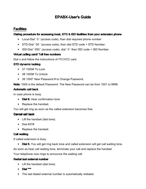
EPABX EPABX--User's GuideFacilities Facilities Dialing procedure for accessing local, STD & ISD facilities from your extension phone Dialing procedure for accessing local, STD & ISD facilities from your extension phone • Local-Dial ' 0 ' (access code), than dial required phone number• STD-Dial ' 00 ' (access code), than dial STD code + STD Number.• ISD-Dial ' 000 ' (access code), dial ' 0 ' than ISD code + ISD Number.Virtual calling card/ Toll free numbers Virtual calling card/ Toll free numbers Dial o and follow the instructions of ITC/VCC card. STD dynamic locking STD dynamic locking• 37 1000# To Lock• 38 1000# To Unlock• 39 1000* New Password # to Change Password.Not Note: e: 1000 is the default Password. The New Password can be from 1001 to 9999. Automatic call back Automatic call back In case phone is busy• Dial 6. Hear confirmation tone• Replace the handset.You will get ring as soon as the called extension becomes free. C ancel call back ancel call back• Lift the handset (dial tone). • Dial #37#• Replace the handset. Call waiting Call waiting If called extension is busy• Dial 5. You will get ring back tone and called extension will get call waiting tone. As soon as hear call waiting tone, terminate your call and replace the handset Your telephone now rings to announce the waiting call. Redial last external number Redial last external number• Lift the handset (dial tone). • Dial ***Dial ***• The last dialed external number is automatically redialed.Call transfer Call transferYou can transfer a call to another extension• While on conversation (incoming call or outgoing call)• Press the Flash and wait for dial tone• Dial the extension number Call T Call Transfer after answer ransfer after answer ransfer after answer• Announce the call.• Replace the handset. Call T Call Transfer before answer ransfer before answer ransfer before answer• Replace the handset. Conference Conference You can establish speech connections with up to seven parties. Only the conference leader (i.e. the person initiating the conference call) can invoke participants. I nitiate a conference nitiate a conference• Call to the first party.• Press the Flash key (dial tone).• Dial the second party's extension number (inform about the conference).• Dial 3.Dial 3.During the conference, conference tone will be heard. A dd a new party in a conference dd a new party in a conference• Press the Flash key (dial tone).• Dial the new party's extension number (inform about the conference).• Dial 3.Dial 3. L eave eave a conference a conference a conference• Replace the handset Note:Note: A tone burst is heard each time a participant enters or leaves the conference. The conversation is changed back to a normal two party connection when there is only two parties left. When the conference leader leaves the conference the conference will continue and the first one to park the conference will be the new conference leader.Individual abbreviated numbers Individual abbreviated numbersUp to ten of your most important and frequently needed telephone numbers can be programmed on your telephone as individual abbreviated numbers 0-9.• Lift the handset (dial tone).• Dial ** (0Dial ** (0--9)9) Programming an abbreviated numbers Programming an abbreviated numbers• Lift the handset (dial tone).• Dial *51* digit (0Dial *51* digit (0--9)* telephone number #.9)* telephone number #.• Replace the handset. E rase an abbreviated number rase an abbreviated number• Lift the handset (dial tone).• Dial #51* digit (0Dial #51* digit (0--9)#.9)#.• Replace the handset. E rase all numbers programmed by the extension rase all numbers programmed by the extension• Lift the handset (dial tone)• Dial #51#.Dial #51#.• Replace the handset. Follow me Follow me To order from your own telephone To order from your own telephone• Lift the handset (dial tone).• Dial *21* extension number of the answering position # (special dial tone).• Replace the handset.Cancel Cancel “Follow “Follow--me” me” from your own telephone from your own telephone from your own telephone• Lift the handset (special dial tone).• Dial #21# (dial tone Dial #21# (dial tone))• Replace the handset. Caller ID Caller ID T race the incoming call race the incoming callIncoming calls numbers are displayed on CID enabled phones. Call EPABX operator Call EPABX operatorFor inquiry/complaints etc dial 7200, 7210, 7200, 7210, 30003000Call pick up Call pick up Dial extension No. of a ringing phone, than dial 8, the call be picked up.Do Not Disturb (DND)Do Not Disturb (DND) This feature is used to avoid incoming calls of the phone. However you can still use the telephone for outgoing calls as usual.The calling party receives a number unobtainable tone and a display message in informing about this feature.• Lift the handset (dial tone). • Dial *27#.Dial *27#.• Replace the handset.C ancel ancel “D “D “Do not disturb o not disturb o not disturb”” • Lift the handset (special dial tone).• Dial #27# (dial tone).Dial #27# (dial tone).• Replace the handset. General Cancellation General CancellationThe following procedure is used to request general cancellation of all programmed features:- • Dial #001#Dial #001#。
Wireshark User's Guide(中文版)
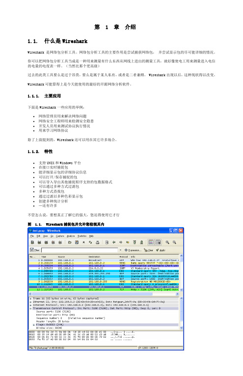
第 1 章介绍1.1. 什么是WiresharkWireshark 是网络包分析工具。
网络包分析工具的主要作用是尝试捕获网络包,并尝试显示包的尽可能详细的情况。
你可以把网络包分析工具当成是一种用来测量有什么东西从网线上进出的测量工具,就好像使电工用来测量进入电信的电量的电度表一样。
(当然比那个更高级)过去的此类工具要么是过于昂贵,要么是属于某人私有,或者是二者兼顾。
Wireshark出现以后,这种现状得以改变。
Wireshark可能算得上是今天能使用的最好的开源网络分析软件。
1.1.1. 主要应用下面是Wireshark一些应用的举例:∙网络管理员用来解决网络问题∙网络安全工程师用来检测安全隐患∙开发人员用来测试协议执行情况∙用来学习网络协议除了上面提到的,Wireshark还可以用在其它许多场合。
1.1.2. 特性∙支持UNIX和Windows平台∙在接口实时捕捉包∙能详细显示包的详细协议信息∙可以打开/保存捕捉的包∙可以导入导出其他捕捉程序支持的包数据格式∙可以通过多种方式过滤包∙多种方式查找包∙通过过滤以多种色彩显示包∙创建多种统计分析∙…还有许多不管怎么说,要想真正了解它的强大,您还得使用它才行图 1.1. Wireshark捕捉包并允许您检视其内1.1.3. 捕捉多种网络接口Wireshark 可以捕捉多种网络接口类型的包,哪怕是无线局域网接口。
想了解支持的所有网络接口类型,可以在我们的网站上找到/CaptureSetup/NetworkMedia.1.1.4. 支持多种其它程序捕捉的文件Wireshark可以打开多种网络分析软件捕捉的包,详见???1.1.5. 支持多格式输出Wieshark可以将捕捉文件输出为多种其他捕捉软件支持的格式,详见???1.1.6. 对多种协议解码提供支持可以支持许多协议的解码(在Wireshark中可能被称为解剖)???1.1.7. 开源软件Wireshark是开源软件项目,用GPL协议发行。
LiteOS_User_Guide 嵌入式操作系统liteos用户向导

LiteOS User’s Guide
Preface
LiteOS provides a UNIX-like environment for sensor networks, networked embedded devices, and cyber physical systems. It provides a thread-based run-time execution environment for applications. The goal of this User’s Guide is to get you familiarized with its environment. For updates, check:
LiteOS User’s Guide
Version 2.1 Last updated: Oct 2 2011
This guide illustrates how to get started as well as an In-depth description of the LiteOS operating system. Download location: Copyright ©2007-2011 LiteOS developers, all rights reserved.
LiteOS User’s Guide
Reporting Memory Contents in LiteOS ..................................................................................... 35 Appendix........................................................................................................................................ 36 Appendix I: A List of LiteShell Commands supported ................................................................ 36 Troubleshooting Tips ..................................................................................................................... 37
i.MX_Linux_User's_Guide

1About This BookThis document explains how to build and install the FreescaleLinux ® OS BSP, where BSP stands for Board SupportPackage, on the i.MX platform. It also covers specialFreescale features and how to use them.This document provides the steps to run the i.MX platform,including board DIP switch settings, and instructions onconfiguring and using the U-Boot bootloader.The later chapters describe how to use some Freescale specialfeatures when running the Linux OS kernel.Features covered in this guide may be specific to particularboards or SOCs. For the capabilities of a particular board orSOC, see the i.MX Linux ® Release Notes (IMXLXRN).1.1AudienceThis document is intended for software, hardware, and systemengineers who are planning to use the product, and for anyonewho wants to understand more about the product.1.2ConventionsThis document uses the following conventions:User's Guide Rev. L3.14.38_6ul-ga, 09/2015i.MX Linux® User's Guide © 2015 Freescale Semiconductor, Inc.Contents1About This Book....................................................12Introduction.............................................................33Basic Terminal Setup..............................................34Booting Linux OS...................................................45Enabling Solo Emulation......................................296Power Management...............................................297Multimedia...........................................................318Graphics.................................................................439Security.................................................................4510Connectivity (46)•Courier New font: This font is used to identify commands, explicit command parameters, code examples,expressions, data types, and directives.1.3Supported hardware SoCs and boardsThese are the systems covered in this guide:•i.MX 6Quad SABRE-SD Board and Platform •i.MX 6DualLite SABRE-SD Platform •i.MX 6Quad SABRE-AI Platform •i.MX 6DualLite SABRE-AI Platform •i.MX 6SoloLite EVK •i.MX 6SoloX SABRE-SD Platform •i.MX 6SoloX SABRE-AI Platform •i.MX 6QuadPlus SABRE-AI platform •i.MX 6UltraLite EVK platformSome abbreviations are used in places in this document.•SABRE-SD refers to the i.MX 6Quad SABRE-SD, i.MX 6DualLite SABRE-SD, and i.MX 7Dual SABRE-SD boards.•SABRE-AI refers to the i.MX 6Quad SABRE-AI, i.MX 6DualLite SABRE-AI, and i.MX 6QuadPlus SABRE-AI boards.•SoloLite refers to the i.MX 6SoloLite Board.•SoloX or SX refer to the i.MX 6SoloX SABRE-SD and SABRE-AI boards.•UL refers to the i.MX 6UltraLite board1.4ReferencesThis release includes the following references and additional information.•i.MX Linux ® Release Notes (IMXLXRN) - Provides the release information.•i.MX Linux ® User's Guide (IMXLUG) - Contains the information on installing U-Boot and Linux OS and using i.MX-specific features.•Freescale Yocto Project User's Guide (IMXLXYOCTOUG) - Contains the instructions for setting up and building Linux OS in the Yocto Project.•i.MX Linux ® Reference Manual (IMXLXRM) - Contains the information on Linux drivers for i.MX.•i.MX 6 Graphics User's Guide (IMX6GRAPHICUG) - Describes the graphics used.•i.MX BSP Porting Guide (IMXXBSPPG) - Contains the instructions on porting the BSP to a new board.•i.MX VPU Application Programming Interface Linux ® Reference Manual (IMXVPUAPI) - Provides the reference information on the VPU API.The quick start guides contain basic information on the board and setting it up. They are on the Freescale website.•SABRE Platform Quick Start Guide (IMX6QSDPQSG)•SABRE Board Quick Start Guide (IMX6QSDBQSG)•SABRE Automotive Infotainment Quick Start Guide (IMX6SABREINFOQSG)•i.MX 6SoloLite Evaluation Kit Quick Start Guide (IMX6SLEVKQSG)Documentation is available online at .•i.MX 6 information is at /iMX6series•i.MX 6 SABRE information is at /imxSABRE•i.MX 6SoloLite EVK information is at/6SLEVK•i.MX 7Dual information is at /webapp/sps/site/prod_summary.jsp?code=i.MX7D•i.MX 6UltraLite information is at /webapp/sps/site/prod_summary.jsp?code=i.MX6UL .2IntroductionThe i.MX Linux BSP is a collection of binary files, source code, and support files that can be used to create a U-Bootbootloader, a Linux kernel image, and a root file system for i.MX development systems. The Yocto Project is the framework of choice to build the images described in this document, although other methods can be used.All the information on how to set up the Linux host machine, how to run and configure a Yocto Project, generate an image,and generate a rootfs, are covered in the Freescale Yocto Project User's Guide (IMXLXYOCTOUG).When Linux OS is running, this guide provides information on how to use some special features that Freescale SoCs provide.The release notes provides the features that are supported on a particular board.3Basic Terminal SetupThe i.MX boards can communicate with a host server (Windows ® OS or Linux OS) using a serial cable. Common serialcommunication programs such as HyperTerminal, Tera Term, or PuTTY can be used. The example below describes the serial terminal setup using HyperTerminal on a Windows host.The i.MX 6Quad/QuadPlus/DualLite SABRE-AI boards connect to the host server using a serial cable.The i.MX 6 SABRE-SD, i.MX 6SoloLite EVK, i.MX 6SoloX SABRE-AI, i.MX 7Dual SABRE-SD, and i.MX 6UltraLite EVK boards connect the host driver using the micro USB connector. The USB to serial driver can be found under /Drivers/VCP.htm .1.Connect the target and the PC running Windows OS using a serial cable on i.MX 6 SABRE-AI boards or a micro-B USB cable on i.MX 6 SABRE boards.2.Open HyperTerminal on the PC running Windows OS and select the settings as shown in the following figure.Figure 1. HyperTerminal settings for terminal setup4Booting Linux OSBefore the Linux OS kernel can boot on an i.MX board, the images (U-Boot, Linux kernel, device tree, and rootfs) need to be copied to a boot device and the boot switches need to be set to boot that device. There are various ways that this can be done for different boards, boot devices, and results desired. This section explains how to prepare a boot device, giving some understanding of where files need to be in the memory map section, specifies switch settings for booting, and describes how to boot Linux OS from U-Boot.4.1Software overviewThis section describes the software needed for the board to be able to boot and run Linux OS. To boot a Linux image, four elements are needed:•Bootloader (U-Boot)•Linux kernel image (zImage)• A device tree file (.dtb) for the board being used• A root file system (rootfs) for the particular Linux imageThe system can be configured for a specific graphical backend. The graphical backends are X11, Wayland, frame buffer, or direct frame buffer.4.1.1BootloaderU-Boot is the tool recommended as the bootloader. U-Boot must be loaded onto a device to be able to boot from it. U-Boot images are board-specific and can be configured to support booting from different sources.The pre-built or Yocto Project default bootloader names start with the name of the bootloader followed by the name of the platform and board and followed by the name of the device that this image is configured to boot from: u-boot-[platform] [board]_[machine configuration].imx. If no boot device is specified, it boots from SD/MMC.The manufacturing tool can be used to load U-Boot onto all devices. U-Boot can be loaded directly onto an SD card using the Linux dd command. U-Boot can be used to load a U-Boot image onto some other devices.4.1.2Linux kernel image and device treeThis Freescale i.MX BSP contains a pre-built kernel image based on the 3.14.38 version of the Linux kernel and the device tree files associated with each platform.The same kernel image is used for all the i.MX boards. Device trees are kernel configuration files that allow a common kernel to boot with different pin settings for different boards or configurations. Device tree files use the .dtb extension. The configuration for a device tree can be found in the Linux source code under arch/arm/boot/dts in the *.dts files.The i.MX Linux delivery package contains pre-built device tree files for the i.MX boards in various configurations. The prebuilt images are named zImage--[kernel]-[platform]-[board]-[configuration].dtb.The *ldo.dtb device trees are used for LDO-enabled feature support. By default, the LDO bypass is enabled. If your board has the CPU set to 1.2 GHZ, you should use the *ldo.dtb device tree instead of the default, because LDO bypass mode is not supported on the CPU at 1.2 GHZ. The device tree *hdcp.dtb is used to enable the DHCP feature because of a pin conflict, which requires this to be configured at build time.4.1.3Root file systemThe root file system package (or rootfs) provides busybox, common libraries, and other fundamental elements.The i.MX BSP package contains several root file systems. The file system includes Freescale-specific libraries and common Linux utilites. They are named with the following convention: [image recipe]-[backend]-[platform][board].[ext3|sdcard]. The ext3 extension indicates a standard file system. It can be mounted as NFS, or its contents can be stored on a boot media such as an SD/MMC card.The graphical backend to be used is also defined by the rootfs.4.2Manufacturing toolThe manufacturing tool, named MFGTool, is a tool that runs on a computer and is used to download images to different devices on an i.MX board. The tar.gz file can be found with the pre-built images.4.2.1Configuring MFGToolUnzip Mfgtools-Rel-[version]_UPDATER.tar.gz.Instructions for MFGTool V2 can be found in the file Profiles/[SOC] Linux Update/OS Firmware/ucl2.xml . Read and update the ucl2.xml file to understand the operations before using MFGTool.It is important to correctly configure the cfg.ini and UICfg.ini files. For example, if only one board is supported,PortMgrDlg=1 should be set in UICfg.ini . If four boards are supported, PortMgrDlg=4 should be set. Incorrect configuration causes MFGTool to malfunction.NOTEFor i.MX 6SoloX, the default settings in the cfg.ini file need to be changed as follows.MFGTool looks for the settings in the ucl2.xml file.[profiles]chip = Linux[platform]board = SabreSD[LIST]name = SDCard[variable]board = sabresd mmc = 0sxuboot=17x17arm2sxdtb=17x17-arm2ldo=4.2.2Using MFGToolFollow these instructions to use the MFGTool V2:1.Connect a USB cable from a computer to the USB OTG port on the board.2.Connect a USB cable from the OTG-to-UART port to the computer for console output.3.Open a Terminal emulator program. See Section "Basic Terminal Setup" in this guide.4.Set the boot pin to Mfgtool mode. See Section "Serial download mode for the Manufacturing Tool" in this guide.5.Choose the correct .vs file and double-click it to launch MFGTool host tool.6.The default profile of the manufacturing tool assumes that your file system is packed and compressed using the bzip2algorithm. An example can be found in the MFGTool release package in the folder Profiles\[SOC] Linux Update \OS Firmware\files. To create this file, run the following commands as a root user on Linux OS. You can alsomodify the profile to support other formats.Figure 2. Programming SD with the manufacturing tool – image downloadingNOTEThe manufacturing tool may sometimes report an error message when it isdownloading the file system to an SD card. This can be caused by insufficientspace on the SD card due to a small partition size. To fix this, unzip the fileProfiles\Linux\OS Firmware\mksdcard.sh.tar and modify the script toincrease the size of the partition and create more partitions according to your filesystem requirements. After the modification is done, tar the script again.4.3Preparing an SD/MMC card to bootThis section describes the steps to prepare an SD/MMC card to boot up an i.MX board using a Linux host machine. These instructions apply to SD and MMC cards although for brevity, often only SD card is listed.For a Linux image to be able to run, four separate pieces are needed: the Linux kernel image (zImage), the device tree file (*.dtb), the U-Boot boot loader image, and the root file system (*.ext3 or *.ext4).A .sdcard image contains all four images properly configured for an SD card. The release contains a pre-built .sdcard image that is built specifically for the i.MX 6QuadPlus SABRE-AI board. It runs the X11 graphical backend. It does not run on other boards unless U-Boot, the device tree, and rootfs are changed.The Yocto Project build creates an SD card image that can be flashed directly. This is the simplest way to load everything needed onto the card with one command.When more flexibility is desired, the individual components can be loaded separately, and those instructions are includedhere as well. An SD card can be loaded with the individual components one-by-one or the .sdcard image can be loaded andthe individual parts can be overwritten with the specific components.The rootfs on the default .sdcard image is limited to a bit less than 4 GB, but re-partitioning and re-loading the rootfs can increase that to the size of the card. The rootfs can also be changed to specify the graphical backend that is used.The device tree file (.dtb) contains board and configuration-specific changes to the kernel. Change the device tree file to change the kernel for a different i.MX board or configuration.By default, the release uses the following layout for the images on the SD card. The kernel image and DTB move to use the FAT partition without a fixed raw address on the SD card. The users have to change the U-Boot boot environment if the fixed raw address is required.4.3.1Preparing the cardAn SD/MMC card reader, such as a USB card reader, is required. It is used to transfer the bootloader and kernel images to initialize the partition table and copy the root file system. To simplify the instructions, it is assumed that a 4GB SD/MMC card is used.Any Linux distribution can be used for the following procedure.The Linux kernel running on the Linux host assigns a device node to the SD/MMC card reader. The kernel might decide the device node name or udev rules might be used. In the following instructions, it is assumed that udev is not used.To identify the device node assigned to the SD/MMC card, carry out the following command:$ cat /proc/partitionsmajor minor #blocks name8 0 78125000 sda8 1 75095811 sda18 2 1 sda28 5 3028221 sda58 32 488386584 sdc8 33 488386552 sdc18 16 3921920 sdb8 18 3905535 sdb1In this example, the device node assigned is /dev/sdb (a block is 512 Bytes).NOTEMake sure that the device node is correct for the SD/MMC card. Otherwise, it maydamage your operating system or data on your computer.4.3.2Copying the full SD card imageThe SD card image (with the extension .sdcard) contains U-Boot, the Linux image and device trees, and the rootfs for a 4 GB SD card. The image can be installed on the SD card with one command if flexibility is not required.Carry out the following command to copy the SD card image to the SD/MMC card. Change sdx below to match the one used by the SD card.$ sudo dd if=<.sdcard image> of=/dev/sdx bs=1M conv=fsyncThe entire contents of the SD card are replaced. If the SD card is larger than 4 GB, the additional space is not accessible.4.3.3Partitioning the SD/MMC cardThe full SD card image already contains partitions. This section describes how to set up the partitions manually. This needs to be done to individually load the bootloader, kernel, and rootfs.There are various ways to partition an SD card. Essentially, the bootloader image needs to be at the beginning of the card. Followed by the Linux image and the device tree file. These can either be in a partition or not. The root file system does need to be in a partition that starts after the Linux section. Make sure that each section has enough space. The example below creates two partitions.On most Linux host operating systems, the SD card is mounted automatically upon insertion. Therefore, before running fdisk, make sure that the SD card is unmounted if it was previously mounted (through sudo umount /dev/sdx).Start by running fdisk with root permissions. Use the instructions above to determine the card ID. We are using sdx here as an example.$ sudo fdisk /dev/sdxType the following parameters (each followed by <ENTER>):p [lists the current partitions]d [to delete existing partitions. Repeat this until no unnecessary partitionsare reported by the 'p' command to start fresh.]u [switch the unit to sectors instead of cylinders]n [create a new partition]p [create a primary partition - use for both partitions]1 [the first partition]20480 [starting at offset sector]1024000 [size for the first partition to be used for the boot images]p [to check the partitions]np21228800 [starting at offset sector, which leaves enough space for the kernel,the bootloader and its configuration data]<enter> [using the default value will create a partition that extends tothe last sector of the media]p [to check the partitions]w [this writes the partition table to the media and fdisk exits]4.3.4Copying a bootloader imageThis section describes how to load only the boot loader image, when the full SD card image is not used. Carry out the following command to copy the U-Boot image to the SD/MMC card.$ sudo dd if=<U-Boot image> of=/dev/sdx bs=512 seek=2 conv=fsyncThe first 1 KB of the SD/MMC card, which includes the partition table, is preserved.4.3.5Copying the kernel image and DTB fileThis section describes how to load the kernel image and DTB when the full SD card image is not used. The pre-built SD card image uses the VFAT partition for storing kernel image and DTB, which requires a VFAT partition that is mounted as a Linux drive and the files are simply copied into it. This is the preferred method.Another method that can be used is for users to put the kernel image and DTB to the fixed raw address of the SD card by using the dd command. The later method needs to modify the U-Boot default environment variables for loading the kernel image and DTB.Default: VFAT partition1.Format partition 1 on the card as VFAT with this command:$ sudo mkfs.vfat /dev/sdx12.Mount the formatted partition with this command:$ mkdir mountpoint $ sudo mount /dev/sdx1 mountpoint3.Copy the zImage and *.dtb files to the mountpoint by using cp . The device tree names should match the mount point specified by U-Boot. Be sure to un-mount the partition with this command:$ sudo umount mountpointAlternative: Fixed raw addressThe following command can be used to copy the kernel image to the SD/MMC card:$ sudo dd if=zImage_imx_v7_defconfig of=/dev/sdx bs=512 seek=2048 conv=fsyncThis copies zImage to the media at offset 1 MB (bs x seek = 512 x 2048 = 1 MB).The i.MX DTB image can be copied by using the copy command and copying the file to the 2nd partition or the following commands copy an i.MX DTB image to the SD/MMC card by using dd . Choose the command for your board:$ sudo dd if=zImage-imx6qp-sabreauto.dtb of=/dev/sdx bs=512 seek=20480 conv=fsync $ sudo dd if=zImage-imx6q-sabreauto.dtb of=/dev/sdx bs=512 seek=20480 conv=fsync $ sudo dd if=zImage-imx6q-sabresd.dtb of=/dev/sdx bs=512 seek=20480 conv=fsync $ sudo dd if=zImage-imx6sl-evk.dtb of=/dev/sdx bs=512 seek=20480 conv=fsync $ sudo dd if=zImage-imx7d-sdb.dtb of=/dev/sdx bs=512 seek=20480 conv=fsyncThis copies the board-specific .dtb file to the media at offset 10 MB (bs x seek = 512 x 20480 = 10 MB).The following command can be used to copy the kernel image to the i.MX 6UltraLite EVK board:$ sudo dd if=zImage-imx6ul-14x14-evk.dtb of=/dev/sdx bs=512 seek=20480 conv=fsync4.3.6Copying the root file system (rootfs)This section describes how to just load the rootfs image when the full SD card image is not used.Copy the target file system to a partition that only contains the rootfs. This example uses partition 2 for the rootfs. First format the partition. The file system format ext3 or ext4 is a good option for the removable media due to the built-in journaling. Replace sdx with the partition in use in your configuration.$ sudo mkfs.ext3 /dev/sdx2Or $ sudo mkfs.ext4 /dev/sdx2Copy the target file system to the partition:$ mkdir /home/user/mountpoint$ sudo mount /dev/sdx2 /home/user/mountpointExtract a rootfs package to a directory: extract fsl-image-gui-imx6qpsabreauto.ext3 to /home/user/rootfs for example:$ sudo mount -o loop -t ext3 fsl-image-gui-imx6qpsabreauto.ext3/home/user/rootfsThe rootfs directory needs to be created manually.Assume that the root file system files are located in /home/user/rootfs as in the previous step:$ cd /home/user/rootfs $ sudo cp -a * /home/user/mountpoint $ sudo umount /home/user/mountpoint $ sudo umount /home/user/rootfs $ syncNOTECopying the file system takes several minutes depending on the size of your rootfs.The file system content is now on the media.4.4Downloading imagesImages can be downloaded to a device using a U-Boot image that is already loaded on the boot device or by using the manufacturing tool, MFGTool. Use a terminal program to communicate with the i.MX boards.4.4.1Downloading images using U-BootThe following sections describe how to download images using the U-Boot bootloader.The commands described below are generally useful when using U-Boot. Additional commands and information can be found by typing help at the U-Boot prompt.The U-Boot print command can be used to check environment variable values.The setenv command can be used to set environment variable values.4.4.1.1Downloading an image to MMC/SDThis section describes how to download U-Boot to an MMC/SD card that is not the one used to boot from.Insert an MMC/SD card into the SD card slot. This is slot SD3 on i.MX 6 SABRE boards and SD1 on i.MX 6SoloLite boards, SD2 on i.MX 6UltraLite EVK board and SD1 on i.MX 7Dual SABRE-SD board.To flash the original U-Boot, see Preparing an SD/MMC card to boot .The U-Boot bootloader is able to download images from a TFTP server into RAM and to write from RAM to an SD card. For this operation, the Ethernet interface is used and U-Boot environment variables are initialized for network communications.The boot media contains U-Boot, which is executed upon power-on. Press any key before the value of the U-Bootenvironment variable, "bootdelay", decreases and before it times out. The default setting is 1 second to display the U-Boot prompt.1.To clean up the environment variables stored on MMC/SD to their defaults, carry out the following command in the U-Boot console:U-Boot > env default -f -a U-Boot > saveU-Boot > reset2.Configure the U-Boot environment for network communications. The folllowing is an example. The lines preceded bythe "#" character are comments and have no effect.U-Boot > setenv serverip <your TFTPserver ip>U-Boot > setenv bootfile <your kernel zImage name on the TFTP server>U-Boot > setenv fdt_file <your dtb image name on the TFTP server>The user can set a fake MAC address through ethaddr enviroment if the MAC address is not fused.U-Boot > setenv ethaddr 00:01:02:03:04:05U-Boot > save3.Copy zImage to the TFTP server. Then download it to RAM:U-Boot > dhcp4.Query the information about the MMC/SD card.U-Boot > mmc devU-Boot > mmcinfo5.Check the usage of the "mmc" command. The "blk#" is equal to "<the offset of read/write>/<block length of thecard>". The "cnt" is equal to "<the size of read/write>/<block length of the card>".U-Boot > help mmcmmc - MMC sub systemUsage:mmc read addr blk# cntmmc write addr blk# cntmmc erase blk# cntmmc rescanmmc part - lists available partition on current mmc devicemmc dev [dev] [part] - show or set current mmc device [partition]mmc list - lists available devices6.Program the kernel zImage located in RAM at ${loadaddr} into the SD card. For example, the command to write theimage with the size 0x800000 from ${loadaddr} to the offset of 0x100000 of the microSD card. See the following examples for the definition of the mmc parameters.blk# = (microSD Offset)/(SD block length) = 0x100000/0x200 = 0x800cnt = (image Size)/(SD block length) = 0x800000/0x200 = 0x4000This example assumes that the kernel image is equal to 0x800000. If the kernel image exceeds 0x800000, increase the image length. After issuing the TFTP command, filesize U-Boot environment variable is set with the number of bytes transferred. This can be checked to determine the correct size needed for the calculation. Use the U-Boot command printenv to see the value.U-Boot > mmc dev 2 0U-Boot > tftpboot ${loadaddr} ${bootfile}### Suppose the kernel zImage is less than 8M.U-Boot > mmc write ${loadaddr} 0x800 0x40007.Program the dtb file located in RAM at ${fdt_addr} into the microSD.U-Boot > tftpboot ${fdt_addr} ${fdt_file}U-Boot > mmc write ${fdt_addr} 0x5000 0x8008.On i.MX 6 SABRE boards, you can boot the system through the rootfs in the SD card by the HannStar LVDS. Thekernel MMC module now uses a fixed mmcblk index for the uSDHC slot. The SD3 slot uses mmcblk2 on i.MX 6 SABRE boards, the SD1 slot uses mmcblk0 on the i.MX 7Dual SABRE-SD board, and the SD2 slot uses mmcblk1 on the i.MX 6UltraLite board.9.Boot the board.U-Boot >setenv bootcmd_mmc 'run bootargs_base mmcargs;mmc dev;mmcread ${loadaddr} 0x800 0x4000;mmc read ${fdt_addr} 0x5000 0x800;bootz ${loadaddr} - ${fdt_addr}'U-Boot > setenv bootcmd 'run bootcmd_mmc'U-Boot > saveenv4.4.1.2Using eMMCThere is an eMMC chip on i.MX SABRE boards. It is accessed through SDHC4 on i.MX 6 SABRE boards or SDHC3 oni.MX 7Dual SABRE-SD board. The following steps describe how to use this memory device.1.Carry out the following command on the U-Boot console to clean up the environments stored on eMMC:U-Boot > env default -f -aU-Boot > saveU-Boot > reset2.Configure the boot pin. Power on the board and set the U-Boot environment variables as required. For example,U-Boot > setenv serverip <your tftpserver ip>U-Boot > setenv bootfile <your kernel zImage name on the tftp server>U-Boot > setenv fdt_file <your dtb image name on the tftp server>### The user can set fake MAC address via ethaddr enviroment if the MAC address is not fusedU-Boot > setenv ethaddr 00:01:02:03:04:05U-Boot > save3.Copy zImage to the TFTP server. Then download it to RAM:U-Boot > dhcp4.Query the information about the eMMC chip.U-Boot > mmc devU-Boot > mmcinfo5.Check the usage of the "mmc" command. "blk#" is equal to "<the offset of read/write>/<block length of the card>"."cnt" is equal to "<the size of read/write>/<block length of the card>".mmc read addr blk# cntmmc write addr blk# cntmmc erase blk# cntmmc rescanmmc part - lists available partition on current mmc devicemmc dev [dev] [part] - show or set current mmc device [partition]mmc list - lists available devices6.Program the kernel zImage into eMMC. For example, the command below writes the image with the size 0x800000from ${loadaddr} to the offset 0x100000 of the eMMC chip. Here, the following equations are used: 0x800=0x100000/0x200, 0x4000=0x800000/0x200. The block size of this card is 0x200. This example assumes that the kernel image is less than 0x800000 bytes. If the kernel image exceeds 0x800000, enlarge the image length.### Select mmc dev 2 (USDHC4) on the i.MX 6 SABRESD board:U-Boot > mmc dev 2 0### Select mmc dev 1 (USDHC3) on the i.MX 7Dual SABRESD board:U-Boot > mmc dev 1 0### Select mmc dev 1 (USDHC2) on the i.MX 6UltraLite EVK board:U-Boot > mmc dev 1 0### Suppose kernel zImage is less than 8 MB:U-Boot > tftpboot ${loadaddr} ${bootfile}U-Boot > mmc write ${loadaddr} 0x800 0x40007.Program the dtb file located in RAM at ${fdt_addr} into the eMMC chip.U-Boot > tftpboot ${fdt_addr} ${fdt_file}U-Boot > mmc write ${fdt_addr} 0x5000 0x8008.Boot up the system through RFS in eMMC by HannStar LVDS. The kernel MMC module now uses the fixed mmcblkindices for the USDHC slots. The eMMC/SD4 slot in i.MX 6 SABRE boards is mmcblk3. The eMMC5.0/SD3 slot on the i.MX 7Dual SABRE board is mmcblk2.。
EPIC_User's_Guide

EPIC-User's GuideTable of ContentsPlug-in Installation (1)Prerequisites (1)Eclipse (1)Perl (1)Considerations when using Cygwin (1)Installing EPIC (1)Uninstalling EPIC (2)Setting Up Preferences (3)General Preferences (3)Code Assist (4)Editor (4)Source Formatter (5)Task Tags (6)Templates (6)Associating Files with the Perl Editor (7)CVS Setup (8)Setting Up the Debugger (9)Perl Projects (10)Creating a Project (10)Perl Include Path (10)Converting an Existing Project (11)Recommended Project Layout (11)Eclipse Basics (13)Perspectives (13)Views (13)Using Perspectives (13)New Perspectives (13)Configuring Perspectives (15)Saving a User Defined Perspective (16)Resetting Perspectives (16)Using Views (17)Opening Views (17)Moving and Docking Views (17)Working with the Perl Editor (18)Syntax Check (18)Explain Errors and Warnings (18)Open Declaration (19)Perldoc (21)Quick Reference (22)Code Assist (22)Variable Inspection (22)Module Inspection (23)Task Markers (23)Templates (24)Defining Templates (24)Using Templates (25)Source Formatter (26)Source Folding (26)Refactoring (27)Extract Subroutine (27)HTML Export (29)Outline View (29)Using the Perl Debugger (30)Launching Perl Programs (30)EPIC-User's GuideLaunching Perl Programs in Run Mode (30)Re-launching a Perl Program (31)Creating Launch Configurations (32)Perl Local:Running a Perl Script on the Local Machine (32)Perl CGI:Run Perl Programs in a CGI Environment (33)Perl Remote:Debug a Perl Script on a Remote Machine (34)Breakpoints (36)Setting Breakpoints (36)Enabling or Disabling Breakpoints (36)Removing Breakpoints (36)Views in the Debug Perspective (37)Debug View (37)Variables View (37)Breakpoints View (39)Perl Expression View (39)Stepping Through the Execution of a Perl Program (40)Step Over (40)Step Into (40)Run to Return (40)RegExp Plug-in (42)Enabling the RegExp View (42)Using the RegExp Plug-in (42)Debugging Regular Expressions (42)Known Bugs&Problems (44)References (45)Plug-in InstallationPrerequisitesEclipseBefore installing the EPIC plug-in,a recent version of Eclipse has to be installed.The minimum re-quirement is version3.1of Eclipse for EPIC'stable'and version3.2of Eclipse for EPIC'testing'.Eclipse comes in two flavors.The SDK version contains Java IDE components and is much largerthan the Platform version.If you only want to use Eclipse as a Perl IDE,the Platform version is suf-ficient.If you are in for Perl and Java coding,use the SDK version.Eclipse does not include a Java Runtime Environment(JRE).You will need a1.4.1level or higherJava Runtime or Java Development Kit(JDK)installed on your machine in order to run Eclipse.Eclipse can be downloaded from [].PerlIn order to have all EPIC features like Syntax Checking,Source Formatting etc.,a Perl interpreter isneeded.In principle any Perl interpreter can be used.To use debugging within Eclipse,Perl version5.8.x or5.6.x is required.For further requirements concerning the debugger,see the section called“Setting Up the Debugger”.Most*nix/Linux installations will provide Perl interpreters out of the box.Perl for Windows can be downloaded from [] Considerations when using CygwinMake sure that the mount command is available and that it is in your system path.As mount is astandard component of Cygwin,you usually just have to add the cygwin\bin directory to your sys-tem path.Installing EPICThe installation is done by using the Eclipse Update Manager.The Update Manager connects to anEPIC Update Site[/updates].The Update Site can also be stored locallyif no Internet connection is available and can be downloaded from the EPIC project page[ht-tp://].After starting Eclipse,select Help#Software and Updates#Find and Install...from the menu.Plug-in InstallationSelect Search for new features to install an press Next.Press the Add Update Site...button for a re-mote installation via HTTP or the Add Local Site...button if the Update Site is available locally.When installing EPIC from remote,enter any desired Name and the URL ht-.tp:///updatesThe warning about the installation of an unsigned feature can be ignored.Eclipse has to be restartedafter installation.Now the EPIC installation should be complete.Uninstalling EPICTo tempoarily disable or uninstall the currently active version of EPIC,select Help#Software andUpdates#Manage Configuration from the menu.Expand the tree in the dialog window which ap-pears and select the EPIC feature.Click on the option Disable in the panel on the right side and re-start Eclipse when asked.At this point EPIC is disabled,but still present on disk.To remove it com-pletely,enter the same dialog again and select the previously disabled version of EPIC(you mayneed to toggle showing disabled features in the dialog's toolbar).The option Uninstall will now re-move the chosen version of EPIC completely.Setting Up PreferencesEPIC preferences can be accessed via Window#Preferences...from the Eclipse Menu. General PreferencesClick on Perl EPIC to open the General Preferences page.General preferences include the location of the Perl interpreter,the option to enable warnings,taintmode and the interval of the source validation.The validation interval indicates when to start validation after the editor becomes idle.Apart from the standard interpreter type,the type can be switched to Cygwin.In this case the@INCpath is mapped to be Cygwin compliant.The two debugger-related preferences work as follows:•Enable debugger console is only useful if you wish to debug EPIC itself and should not be activ-ated otherwise.This preference causes a special console to become available while debuggingPerl scripts.The console shows internal communication between EPIC and the Perl debuggerbackend.To access this console,you have to click on the item perl-d in the Debug view.•Suspend debugger at first statement(active by default)causes the debugger to stop right at the be-ginning of the debugged script,even if there are no breakpoints set.If this preference is inactive,then the debugger will not suspend until the first breakpoint is hit(or the script finishes execu-tion).NoteOn slower systems it might be useful to disable automatic syntax validation.Syntax validation is still possible by using the Shift-F5function key.Code AssistOn the Code Assist Preference Page the auto completion trigger characters are defined.Normally itshould not be necessary to change these values.By default the editor suggests a list of already used variables when the characters$@%are typed.To switch this feature off,deselect the Inspect Variables check box.EditorThese options define the appearance of the Perl Editor,the coloring of the Perl source code,andhow annotations are displayed.Smart typing settings allow to switch auto-completion of quotes,parenthesis etc.on or off.Source FormatterEPIC uses PerlTidy to format source code.The Source Formatter Preference allows to specify Per-lTidy command line parameters.To get a description of available parameters,press the Help keyand select PerlTidy options from the popup menu.NoteIn order for PerlTidy to work correctly,the Perl Interpreter Preferences have to be setup correctly(see above).Task TagsIn this section,you can specify a list of keywords that act as markers for tasks inside comments inyour Perl code,i.e.tags that mark the beginning of a task entry.By default,the words TODO and TASK mark the beginning of a task.Check the Ignore Case option if you want EPIC to recognize task tags case-insensitively,e.g.#todo my task.If you select Allow whitespace,task tags do not need to follow a comment sign(#)directly,e.g.#TODO my task instead of having to write#TODO my task.See the section called“Task Markers”to see how to use Task Tags in the Perl Editor. TemplatesTemplates are a powerful tool to insert pre-defined code snippets while working with the Perl Edit-or.How Templates are use is covered in Working with the Perl Editor.The Templates Preference pageallows the creation,import and export of Templates.Exported Templates are stored in XML format.Associating Files with the Perl EditorEclipse associates file extensions with editors.If another plug-in is installed,the EPIC Perl Editormight not be used as the default editor when opening*.pl,*.pm or*.cgi files.To associate these fileextensions with the Perl Editor,choose Window#Preferences...from the Eclipse menu and selectWorkbench#File Associations.If the Perl extensions are missing,they can be created by pressingthe Add...button.Select the Perl Editor from the list and press the Default button.NoteRegrettably,there is currently no way[]to associate EPIC with script files that do not have any specific extension but instead begin with the#!/usr/bin/perl line.CVS SetupBy default,Eclipse stores Perl files as binary when they are added to the CVS repository.To storePerl files as text(ASCII),select Window#Preferences...from the Eclipse menu and modify theTeam#File Content settings.Add your Perl extensions(pl,pm etc.)by pressing the Add...buttonand specify ASCII in the Contents column.Setting Up PreferencesSetting Up the DebuggerSetting up the debugger requires two steps:1.Define the Perl interpreter to use.2.Install the PadWalker Perl module.NoteIt is possible to use the debugger without installing PadWalker,but in this case local variables won't be shown.Download the PadWalker module from CPAN[/](PadWalker 1.5[ht-tp:///%7Erobin/PadWalker-0.10/])and install as described in the installation notes or use the installation manager provided with your Perl installation(e.g.PPM for ActiveState installa-tions).Earlier versions of EPIC provided a custom-compiled version of PadWalker for ActiveState5.8.x.This is no longer necessary;you should simply use the most recent version of PadWalker distributed by Act-iveState.Perl ProjectsCreating a ProjectPerl projects are created(like any other project)by selecting File#New#Project...from the Eclipsemenu.Follow the wizard's instructions to create your Perl Project.Perl Projects appear with a customfolder icon in the Navigator view:Perl Include PathTo add entries to a project's Perl Include Path(@INC),right click on the project icon and selectProperties....If non-absolute paths are entered,they are interpreted as relative to the project folder.Standard Ec-lipse variables(e.g.${project_loc})can also be used.Converting an Existing ProjectTo add the Perl Nature to an existing project,select the project in the Navigator and select Add PerlNature from the context menu.To remove the Perl Nature from a project,select the project and select Remove Perl Nature from thecontext menu.Recommended Project LayoutIn order to avoid problems with syntax validation(such as packages reported missing)and the de-bugger(such as skipped breakpoints),it is best to organize your project according to the conventionsof the core Perl distribution:•Keep your own modules in dedicated subtrees of your project.For example,create a subdirectorylib as the root of the subtree containing all*.pm files.Note that you can have more than onesuch subtree.For example,you could also create test/lib to store modules that are only im-ported by test scripts.•Add the root directories of your subtrees to the@INC path(see the section called“Perl Include Path”).For example,add the entries lib and test/lib there.•Map package names to paths in the subtree(and vice versa).For example,store code for the pack-age Foo::Bar in file lib/Foo/Bar.pm and ensure that lib/Foo/Baz.pm contains only package Foo::Baz.•Store your Perl scripts anywhere you like in the project.For example,in subdirectory bin or cgi-bin.•To import from a package,use it,rather than require it.For example,use Foo::Bar; rather than require'../lib/Foo/Bar.pm';Eclipse BasicsPerspectivesEach Workbench window contains one or more perspectives.A perspective defines the initial setand layout of views in the Workbench window.Within the window,each perspective shares thesame set of editors.Each perspective provides a set of capabilities aimed at accomplishing a specifictype of task or works with specific types of resources.For example,the Java perspective combinesviews that you would commonly use while editing Java source files,while the Debug perspectivecontains the views that you would use while debugging Java programs.As you work in the Work-bench,you will probably switch perspectives frequently.Perspectives control what appears in certain menus and toolbars.They define visible action sets,which you can change to customize a perspective.You can save a perspective that you build in thismanner,making your own custom perspective that you can open again later.You can set your Workbench preferences to open perspectives in the same window or in a new win-dow.The main perspectives for developing Perl applications are:This is the main perspective for coding Perl scripts.Provides the main functionality for debugging and executing Perl scripts.For detailssee the section called“Views in the Debug Perspective”.ViewsViews support editors and provide alternative presentations as well as ways to navigate the informa-tion in your Workbench.For example,the Navigator view displays projects and other resources thatyou are working with.Views also have their own menus.To open the menu for a view,click the icon at the left end of theview's title bar.Some views also have their own toolbars.The actions represented by buttons onview toolbars only affect the items within that view.A view might appear by itself,or stacked with other views in a tabbed notebook.You can changethe layout of a perspective by opening and closing views and by docking them in different positionsin the Workbench window.Using PerspectivesNew PerspectivesThere are several ways to open a new perspective within this Workbench window:•Using the Open Perspective button on the shortcut bar.•Choosing a perspective from the Window#Open Perspective menu.To open one by using the shortcut bar button:1.Click on the Open Perspective button.2.A menu appears showing the same choices as shown on the Window#Open Perspective menu.Choose Other from the menu.3.In the Select Perspective dialog choose Debug and click OK.The Debug perspective is displayed.4.There are several other interesting things to take note of.•The title of the window now indicates that the Debug perspective is in use.•The shortcut bar contains several perspectives,the original Resource perspective,the new De-bug perspective and a few others.The Debug perspective button is pressed in,indicating that itis the current perspective.•To display the full name of the perspective right click the perspective bar and check ShowText.5.In the shortcut bar,click on the Resource perspective button.The Resource perspective is onceagain the current perspective.Notice that the set of views is different for each of the perspectives. Configuring PerspectivesIn addition to configuring the layout of a perspective you can also control several other key aspectsof a perspective.These include:•The New menu.•The Window#Open Perspective menu.•The Window#Show View menu.•Action sets that show up on the toolbar.Try customizing one of these items.1.In the shortcut bar click on the Resource perspective.2.Select Window#Customize Perspective....3.Select the Commands tab.4.Check Launch and click OK.5.Observe that the toolbar now includes buttons for debug/run launching.6.After experimenting with the other options on the Customize Perspective dialog,choose Window#Reset Perspective to return the perspective to its original state.Saving a User Defined PerspectiveIf you have modified a perspective by adding,deleting,or moving(docking)views,you can saveyour changes for future use.1.Switch to the perspective that you want to save.2.Click Window#Save Perspective As.3.Type a new name for the perspective into the Name field.4.Click OK.Resetting PerspectivesTo restore a perspective to its original layout:1.Click Window#Preferences.2.Expand Workbench and choose Perspectives.3.From the Available perspectives list,select the perspective you want to restore.4.Click Reset.5.Click OK.Using ViewsOpening ViewsPerspectives offer pre-defined combinations of views and editors.To open a view that is not in-cluded in the current perspective,select Window#Show View from the main menu bar.You can create fast views to provide a shortcut to views that you use often.After adding a view to the current perspective,you may wish to save your new layout by clickingWindow#Save Perspective As.Moving and Docking ViewsTo change the location of a view in the current perspective:1.Drag the view by its title bar.Do not release the left mouse button yet.2.As you move the view around the Workbench,the mouse pointer changes to one of the dropcursors shown in the table below.The drop cursor indicates where the view will be docked if yourelease the left mouse button.To see the drop cursor change,drag the view over the left,right,top,or bottom border of another view or editor.3.When the view is in the location that you want,relative to the view or editor area underneath thedrop cursor,release the left mouse button.4.(Optional)If you want to save your changes,select Window#Save Perspective As from themain menu bar.5.Note that a group of stacked views can be dragged using the empty space to the right of the viewtabs.Working with the Perl EditorSyntax CheckEPIC performs on the fly syntax check of Perl source files.In order for the Syntax Check to work,the Perl Interpreter has to be set up correctly(see Setting Up Preferences).The Syntax Check is performed after a defined idle period,after the user has stopped typing.Thisidle period can be configured in the preferences.When an error/warning has been found,the editor displays the appropriate icon in the annotationruler(the gray bar on the left side of the editor),underlines the error in the source,and inserts amarker into the Problems view.A syntax check can be enforced by pressing Shift-F5.It is also triggered automatically by saving asource file.Explain Errors and WarningsIn addition to displaying warnings and errors,the editor is capable of explaining them in more de-tail.To get an Error/Warning explanation,right-click the Error/Warning icon and select Explain Errors/Warnings from the context menu.The explanation(s)will be displayed in the Explain Errors/Warnings view:Open DeclarationOpen Declaration allows the user to search for the declaration of a specific subroutine or package.The search first determines what is selected.If no text is selected,it attempts to find a subroutine or package name at the current cursor position.The search will fail if neither is selected.Due to the dynamic nature of Perl programs,the search is not entirely reliable.For package names and subroutine names qualified by a package prefix,an attempt will be made to locate the appropri-ately named module file using the@INC path.For unqualified subroutine names,the search will first occur in the current editor and then extend to modules referenced by'use'and(literal)'require' statements.If the declaration is found,it will be highlighted in an existing or new editor.PerldocTo retrieve Perldoc information,select a keyword or text and choose Perldoc from the context menuor press Shift-Ctrl-H.If nothing is selected,an input dialog will appear.The search is performed among built-in Perl functions,FAQs from the Perl documentation,andmodules on the include path(see the section called“Perl Include Path”).If Perldoc entries arefound,they are displayed inside the Perldoc view.NotePerldoc has to be installed and available in the system PATH,otherwise this feature will not work. Quick ReferenceApart from Perldoc support,a quick reference feature is available.This feature has the advantagethat no perldoc has to be installed on the system but does not provide as much information as perl-doc.To view the Quick Reference,select a keyword and move the mouse pointer over the selection.A tooltip with a short description of the keyword should appear.Code AssistCode Assist features try to assist the user during source code editing.NoteThe features currently implemented in EPIC may not be fully functional but will be improved in the fu-ture.Variable InspectionWhen you press one of the auto completion characters$@%,the editor displays all defined vari-ables in a list.From the list you can select the variable that should be inserted in the source code.Module InspectionThe editor tries to display methods available in modules when the auto completion characters>or:are entered.NoteCurrently,indirect object invocations are not recognized by code assist.This code block will not work: $smtp=new Net::SMTP;$smtp->[no content assist]This one will work:$smtp=Net::SMTP->new();$smtp->[content assist]Task MarkersTask markers are a very convenient way to add items to the Eclipse task list.A task marker is gener-ated when a#TODO any text is found in the Perl source code.On deletion of the#TODO com-ment,the task marker is also deleted.You can customize the keywords which begin task markers in the preferences(see the section called“Task Tags”).TemplatesTemplates allow for easy insertion of predefined text segments.In addition to normal text these seg-ments can also include pre-defined variables that are included at runtime as well as variables that arespecified by the user when the template is inserted.Defining TemplatesTemplates are defined in the EPIC Preferences(Window#Preferences...).To define a new tem-plate,press the New...button.To insert pre-defined variables,press the Insert Variable...button.In addition to pre-defined variables,the user can specify additional variables(using the syntax${varname})which can be edited when the template is inserted.When the first variable is inser-ted,variables with the same name will automatically be changed.Using TemplatesTemplates are invoked by typing some characters and pressing Ctrl-Space.Templates matching the typed characters will be displayed in a list.A preview is also available.If the template contains user defined variables the user can press the TAB key to jump to the nextvariable after the template has been inserted.Source FormatterEPIC uses PerlTidy for source code formatting(PerlTidy is included in the EPIC package).To format the source code,select Source#Format from the Eclipse menu or use Ctrl-Shift-F.PerlTidy settings can be changed in the Source Formatter preference page.NoteSource formatting might take a while if the source code has a lot of lines.Source FoldingThe editor supports folding of POD comments and subroutines.Source folding can be disabled in the Editor preference page.NoteOn big files source folding can decrease performance.So if you experience slowdowns,disabling source folding might help.RefactoringExtract SubroutineExtraction of subroutines is supported by the use of the CPAN Devel::Refactor module.To extract a subroutine,mark the code to extract and select Refactor#Extract Subroutine from thepopup menu.In the popup menu insert the name of the new subroutine and press Enter.The new subroutine will be placed at the end of the Perl script(before__END__section)and the selection will be replaced with the subroutine call.NoteThe extraction might not work properly at the moment because the Devel::Refactor module is in anearly stage of development.With upcoming versions of the module,this function should become more reliable.HTML ExportTo export,select Source #Export #HTML from the Eclipse menu and specify an output file.HTML export settings can be changed in the Source Formatter preference page.NoteFor HTML export to work,a working Source Formatter is needed (see the section called “Source Formatter”).Outline ViewThe Outline view displays packages and subroutines defined in the edited file.Modules referenced by 'use'statements are also shown.When you click on a module or subroutine name in the outline,the editor will jump to the appropriate position in the source code.When the cursor is moved inside of a subroutine's definition,the subroutine will become selected in the outline.Subroutines named new will get a differenticon.Working with the Perl EditorUsing the Perl DebuggerLaunching Perl ProgramsYou may launch your Perl programs from the workbench.Programs may be launched in either runor debug mode.•In run mode,the program executes,but may not be suspended or examined.•In debug mode,execution may be suspended and resumed,variables may be inspected,and ex-pressions may be evaluated.The environment a Perl program is to be executed in is defined via"Launch Configurations".Alaunch configuration defines•if the program is to be executed in a CGI or normal Perl environment•the host the program is to be executed on•the program to execute•execution parameters to pass•environment variables•configuration data for the web server used to provide the CGI frameworkLaunching Perl Programs in Run Mode1.Select Run#Run...from the Eclipse menu.2.Within the appearing dialog,select the configuration type:•Perl Local:Run a Perl script on the local machine•Perl CGI:Run Perl programs in a CGI environment on the local machine•Perl Remote:Run a Perl script on a remote machineand press the New button to create a new launch configuration.3.Adjust launch configuration attributes.For details see the section called“Creating Launch Con-figurations”.4.Press the Run button.This executes the program.The program's console output will be shown in the console window.For"Perl Local"and"Perl Remote"configurations,the console window also accepts keyboard input tobe passed to the program.If you switch to the debug view,you have additional control over the execution of the program.Fordetails see the section called“Debug View”.Re-launching a Perl ProgramThe workbench keeps a history of each launched and debugged program.To relaunch a program,doone of the following:•Select a previous launch from Run or Debug button pull-down menus.•From the menu bar,select Run#Run History or Run#Debug History and select a previouslaunch from these sub-menus.•In the Debug view,select a process that you want to relaunch,and select Relaunch from the pro-cess's pop-up menu.To relaunch the most recent launch,do one of the following:•Click the Run or Debug buttons(without using the button pull-down menu).•Select Run#Run Last Launched(Ctrl-F11),or Run#Debug Last Launched(F11)from theworkbench menu bar.Creating Launch ConfigurationsPerl Local:Running a Perl Script on the Local Machine1.Enter the name for the launch configuration in the Name field.2.In the Main tab•Project field:select the project which contains the script to executeNoteOnly Perl projects(projects associated with a Perl nature)will be shown.If the project you require is not shown,see the section called“Converting an Existing Project”for adding a Perl nature to your。
EVE USER'S GUIDE

Table of Contents
Getting Started: Registration ......................................................................................................................... 6
Personal Zone: Groups .......................................................................................... 11
BMS电池管理系统使用说明书user'sguideofBMS

BMS电池管理系统使用说明书user'sguideofBMS1.系统介绍BMS(Battery Management System)是一种用于电池管理和监控的系统,用于确保电池的安全性和性能。
本说明书将向您介绍如何正确使用BMS系统。
2.安装准备在安装BMS之前,请确保已经关闭电池电源,并且适当地接地。
检查并确保所有电缆和连接器都牢固连接。
BMS应安装在通风良好且干燥的地方。
3.硬件连接将BMS的正极连接到电池组的正极,将BMS的负极连接到电池组的负极。
确保连接稳固并紧固好螺钉。
检查所有连接以确保没有松动或接触不良。
4.功能设置通过连接到BMS的终端设备,您可以进行BMS的功能设置。
根据实际需要,您可以设置电池容量、单体电压范围、充电和放电限制等参数。
确保在设置参数之前详细阅读BMS的用户手册。
5.监测和报警BMS可以实时监测电池的状态,并且在有异常情况时发出警报。
当电压、温度或电流超出设定范围时,BMS会通过声音、灯光或终端设备上的警报通知您。
请确保及时处理警报情况以防止任何意外损害。
7.警告事项在使用BMS时,请务必注意以下事项:-严禁使用非原厂或非推荐的电池组、传感器或其他配件。
-不得擅自改动BMS系统的电路或参数设置,以避免损坏电池组或危险情况。
-不得将电池组连接到逆变器或电网上,以免造成损坏或危险。
-定期检查和保养BMS系统,确保所有连接和电缆都处于良好状态。
8.常见问题解答Q:BMS系统无法正常启动怎么办?A:检查电池组和BMS的连接是否正确并稳固,确保BMS的电源供应正常。
Q:BMS报警灯持续闪烁是什么意思?A:持续闪烁的报警灯通常表示电池组的电压、温度或电流超过了设定范围,请及时采取相应的措施。
DELL P2314H 用户手册 用户指南 user‘s guide

即插即用功能 . . . . . . . . 通用串行总线(USB)接口 液晶显示器质量和像素政策 维护指南 . . . . . . . . . . .
. . . .
. . . .
. . . .
. . . .
. . . .
. . . .
. . . .
. . . .
. . . .
. . . .
. . . .
3
故障排除 . . . . . . . . . . . . . . . . . . . . . . . . . . . . . . . . . . . . . . . . . . . . . . . 48
自检 . . . . . . . . . . . . . . . . . 内置诊断 . . . . . . . . . . . . . . 常见问题 . . . . . . . . . . . . . . 产品特定问题 . . . . . . . . . . . 通用串行总线(USB)特定问题 . . . . . . . . . . . . . . . . . . . . . . . . . . . . . . . . . . . . . . . . . . . . . . . . . . . . . . . . . . . . . . . . . . . . . . . . . . . . . . . . . . . . . . . . . . . . . . . . . . . . . . . . . . . . . . . . . . . . 48 49 50 54 55
. . . .
. . . .
. . .
. . . .
. . . .
. . . .
. . . .
VCA2617EVM User's Guide

User's GuideSBOU033–November2005This document provides the information needed to set up and operate theevaluation module(EVM).For a more detailed description of theproduct datasheet available from the Texas InstrumentsThroughout this document,the acronym EVM and thephrase synonymous with the VCA2617EVM.This user's guideincludes setup and configuration instructions,information regarding operatingprocedures and input/output connections,an electrical schematic,printed circuit board(PCB)layout drawings,and a parts list for the EVM.Contents1Description (2)2Power Supply Requirements (2)3Input Signals (2)4VCA Control Voltage(V CNTL) (2)5Output Configuration (2)6Clamping Voltage (3)7Switch Settings (3)8Physical Description (3)List of Figures1Switch SW1Settings (3)2VCA2617EVM Schematic (4)3VCA2617EVM PCB Top Layer(Top View) (5)4VCA2617EVM PCB Power Layer(Top View) (6)5VCA2617EVM PCB Ground Layer(Top View) (7)6VCA2617EVM PCB Bottom Layer(Bottom View) (8)List of Tables1Switch SW1Summary (3)2VCA2617EVM Parts List (9)All trademarks are the property of their respective owners.1Description2Power Supply Requirements2.1Voltage LimitsWarning3Input Signals4VCA Control Voltage (V CNTL )5Output ConfigurationDescriptionThe VCA2617EVM is designed to provide ease of use in evaluating the performance of the VCA2617variable gain amplifier.By using the 0Ωjumpers and DIP-switches,the VCA2617EVM can be configured to accommodate several different modes of operation.Before starting the evaluation,it is recommended to review the state of each of the switches to verify the desired configuration.The VCA2617EVM requires a +5V DUT supply (at connector JP1)for the VCA2617,and separate ±5V supplies (at connector JP2)for the output amplifiers (U1and U2).This configuration allows for the monitoring of supply currents to the VCA2617independent of the rest of the evaluation board.Ifmonitoring the supplies is not required,a single +5V supply can be substituted for the two separate +5V supplies.In this case,the –5V supply is still required.Please note that the pull-up resistors R17,R18and R19are connected to the +5V supply,which is required to operate the VCA2617.The default configuration of the EVM is for the differential input configuration of the VCA2617.Here,a single-ended input signal may be applied to SMA connectors J3(PIN_A)and J4(PIN_B).The transformer will convert the signal into a differential signal and drive the VCA.Alternatively,each of the VCA2617inputs can also be driven in single-ended configuration.To do so,use the appropriate solder switches (SJPn)for the desired configuration.Please note that the VCA2617inputs are internally biased and therefore must be ac-coupled.While the VCA2617allows controlling both channels independently,the default configuration of the EVM has both V CNTL pins tied together.An external control voltage can be applied at connector JP1(pin 1).In order to change to independent control,simply reconfigure the solder switches SJP9and SJP10.Access to the V CNTL pins is then provided through SMA connectors J9and J10.This signal can beor waveform.The typical range for the control voltage,as specified in the is from 0.2V to 2.3V.The differential outputs of the VCA2617are fed into an amplifier stage set with a gain of 0.5V/ing the 0Ωjumpers,this stage can be configured in two different ways:•as a single-ended inverter (R23,R24—closed,R22,R25—open),or•as a difference amplifier (R22,R25—closed,R23,R24—open;this is the default configuration).After the amplifier stage,the signal outputs are provided at SMA connectors J5(OUT_A)and J6(OUT_B).The differential outputs of the VCA2617can be terminated with 500Ωon each output,and the output signals can then be checked at test points TP1and TP2and test points TP3and TP4,respectively.6Clamping Voltage7Switch SettingsSW18Physical Description8.1PCB Layout Clamping VoltageThe VCA2617allows for a user to limit the output voltage swing to a defined level.For this configuration, the desired clamping voltage level is applied to the V CLMP A and V CLMP B pins of the VCA2617.The EVM includes a3.3V reference(U3)that supplies a stable ing potentiometer RP1,the clamping voltage can be adjusted to the desired value.Use switch SW1to control the post-gain and power-down functions of the VCA2617.(See Figure1and Table1.)Figure1.Switch SW1SettingsTable1.Switch SW1SummaryHG A/HG B PDON=H(5V)Low-Gain Mode(–16dB to+32dB range)Normal operationOFF=L(0V)High-Gain Mode(–10dB to+38dB range)Power-down modeThis section describes the physical characteristics and PCB layout of the evaluation module,and lists the components used in the VCA2617EVM.The EVM is constructed on a four-layer,4.5in x3.5in PCB using FR-4material.Figure2shows the schematic of the VCA2617EVM.Figure3through Figure6give a brief description of the individual layers.c n t r lV _C l a m +V c n t r l V c n t r l V _C l a m 3)W 1i s n o t i n s t a l l e d 4)D o t t e d l i n e s d e n o t e d e f a u l t s o l d e r j u m p e r f o r S J P 7-S J P 103)J 1,J 2a r e n o t i n s t a l l e d Physical DescriptionFigure 2.VCA2617EVM SchematicPhysical DescriptionFigure3.VCA2617EVM PCB Top Layer(Top View) Physical DescriptionFigure4.VCA2617EVM PCB Power Layer(Top View)Physical Description Physical DescriptionFigure6.VCA2617EVM PCB Bottom Layer(Bottom View)Physical Description 8.2Parts ListThe Parts List,showing the components used in the assembly of the VCA2617EVM,is given in Table2.Table2.VCA2617EVM Parts ListDesignator Value Quantity Description Footprint Part Number NoteC1–C8,0.01µF10Ceramic0603399-1092-1-NDC11,C15C9,C10,C12,C13,0.1µF12Ceramic0603399-1282-1-NDC16–C23C14 1.0µF1Ceramic0805399-1284-1-NDC24–C26 2.2µF3Low Profile Tantalum Capacitor3216/A399-1257-1-NDC27,C28 3.9µF2Ceramic,X5R,Variable Footprint0805/1206C1206C395K3PACTUC29–C3110µF3Low Profile Tantalum Capacitor3528/B TAJB106K016RR22,R250Ω21/10W0805Chip Resistor0805R20,R21,0Ω41/10W0805Chip Resistor0805Not Installed R23,R24R1,R249.9Ω21/10W0805Chip Resistor0805R3–R6169Ω41/10W0805Chip Resistor0805R7,R8249Ω21/10W0805Chip Resistor0805R9,R10332Ω21/10W0805Chip Resistor0805R11,R12499Ω21/10W0805Chip Resistor0805R13,R141kΩ21/10W0805Chip Resistor0805R15,R162kΩ21/10W0805Chip Resistor0805R17–R1910kΩ31/10W0805Chip Resistor08050.4in(9.52mm)RP110kΩ1Bourns3296Series Pot Digi-Key#3296Y-103-NDSquareSwitch,3-Position,DIPSW113POS_SPST_DIP Newark55F5001EXT ROCK SEALEDT1,T22RF Transformer MINI-Circuits T1-1T TTWB T1-1T-KK81TP1–TP44Test Point-Single0.025in Pin test_point_85mil Digi-Key#5007K-ND Not InstalledW11Pin Strips Header3x1Not InstalledJ3–J108SMA SMA_JACK AMP901-144-8RFX or equivalentJ1,J22SMA Not InstalledJP1,JP22Terminal Block,3.5mm3-Position PCB3P-TERM Digi-Key#ED1515-NDJP3,JP426-Pin Right Angle Connector SIP6Not InstalledStand Offs4Spacer,Self-Retain#4Screw1/2in Digi-Key#SRS4-8-01-ND DUT1VCA261732-pin QFN TI,VCA2617RHBU1,U22OPA842or Equivalent SOT23TI,OPA842DBVU31REG1117,3.3V Voltage Regulator SOT223TI,REG1117-3.3 Physical DescriptionFCC WarningsThis equipment is intended for use in a laboratory test environment only.It generates,uses,and can radiate radio frequencyenergy and has not been tested for compliance with the limits of computing devices pursuant to subpart J of part15of FCC rules, which are designed to provide reasonable protection against radio frequency interference.Operation of this equipment in other environments may cause interference with radio communications,in which case the user at his own expense will be required to take whatever measures may be required to correct this interference.EVM TERMS AND CONDITIONSTexas Instruments(TI)provides the enclosed Evaluation Module and related material(EVM)to you,the user,(you or user)SUBJECT TO the terms and conditions set forth below.By accepting and using the EVM,you are indicating that you have read, understand and agree to be bound by these terms and conditions.IF YOU DO NOT AGREE TO BE BOUND BY THESE TERMS AND CONDITIONS,YOU MUST RETURN THE EVM AND NOT USE IT.This EVM is provided to you by TI and is intended for your INTERNAL ENGINEERING DEVELOPMENT OR EVALUATIONPURPOSES ONLY.It is provided“AS IS”and“WITH ALL FAULTS.”It is not considered by TI to be fit for commercial use.Assuch,the EVM may be incomplete in terms of required design-,marketing-,and/or manufacturing-related protective considerations, including product safety measures typically found in the end product.As a prototype,the EVM does not fall within the scope of the European Union directive on electromagnetic compatibility and therefore may not meet the technical requirements of the directive.Should this EVM not meet the specifications indicated in the EVM User’s Guide,it may be returned within30days from the date of delivery for a full refund of any amount paid by user for the EVM,which user agrees shall be user’s sole and exclusive remedy.THE FOREGOING WARRANTY IS THE EXCLUSIVE WARRANTY MADE BY TI TO USER,AND IS IN LIEU OF ALL OTHERWARRANTIES,EXPRESSED,IMPLIED,OR STATUTORY,INCLUDING ANY WARRANTY OF MERCHANTABILITY,FITNESS FOR ANY PARTICULAR PURPOSE OR NON-INFRINGEMENT.TI shall have no obligation to defend any claim arising from the EVM,including but not limited to claims that the EVM infringes third party intellectual property.Further,TI shall have no liability to user for any costs,losses or damages resulting from any sucher shall indemnify and hold TI harmless against any damages,liabilities or costs resulting from any claim,suit orproceeding arising from user’s handling or use of the EVM,including but not limited to,(i)claims that the EVM infringes a thirdparty’s intellectual property,and(ii)claims arising from the user’s use or handling of the EVM.TI shall have no responsibility to defend any such claim,suit or proceeding.User assumes all responsibility and liability for proper and safe handling and use of the EVM and the evaluation of the EVM.TI shall have no liability for any costs,losses or damages resulting from the use or handling of the er acknowledges that the EVM may not be regulatory compliant or agency certified(FCC,UL,CE,etc.).Due to the open construction of the EVM it is the user’s responsibility to take any and all appropriate precautions with regard to electrostatic discharge.EXCEPT TO THE EXTENT OF THE USER’S INDEMNITY OBLIGATIONS SET FORTH ABOVE,NEITHER PARTY SHALL BE LIABLE TO THE OTHER FOR ANY INDIRECT,SPECIAL,INCIDENTAL,OR CONSEQUENTIAL DAMAGES WHETHER TI IS NOTIFIED OF THE POSSIBILITY OR NOT.TI currently deals with a variety of customers for products,and therefore our arrangement with the user is not exclusive.TI assumes no liability for applications assistance,customer product design,software performance,or infringement of patents or services described herein.User agrees to read the EVM User’s Guide and,specifically,the EVM warnings and Restrictions notice in the EVM User’s Guide prior to handling the EVM and the product.This notice contains important safety information about temperatures and voltages.It is user’s responsibility to ensure that persons handling the EVM and the product have electronics training and observe goodlaboratory practice standards.By providing user with this EVM,product and services,TI is NOT granting user any license in any patent or other intellectualproperty right.EVM WARNINGS AND RESTRICTIONSIt is important to operate this EVM within the input voltage range of±5V and the output voltage range of±5V.Exceeding the specified input range may cause unexpected operation and/or irreversible damage to the EVM.If there arequestions concerning the input range,please contact a TI field representative prior to connecting the input power.Applying loads outside of the specified output range may result in unintended operation and/or possible permanent damage to the EVM.Please consult the EVM User's Guide prior to connecting any load to the EVM output.If there is uncertainty as to the load specification,please contact a TI field representative.During normal operation,some circuit components may have case temperatures greater than+50°C.The EVM is designed tooperate properly with certain components above+50°C as long as the input and output ranges are maintained.These components include but are not limited to linear regulators,switching transistors,pass transistors,and current sense resistors.These types of devices can be identified using the EVM schematic located in the EVM User's Guide.When placing measurement probes near these devices during operation,please be aware that these devices may be very warm to the touch.Mailing Address:Texas Instruments,Post Office Box655303,Dallas,Texas75265Copyright©2005,Texas Instruments IncorporatedIMPORTANT NOTICETexas Instruments Incorporated and its subsidiaries (TI) reserve the right to make corrections, modifications, enhancements, improvements, and other changes to its products and services at any time and to discontinue any product or service without notice. Customers should obtain the latest relevant information before placing orders and should verify that such information is current and complete. All products are sold subject to TI’s terms and conditions of sale supplied at the time of order acknowledgment.TI warrants performance of its hardware products to the specifications applicable at the time of sale in accordance with TI’s standard warranty. T esting and other quality control techniques are used to the extent TI deems necessary to support this warranty. Except where mandated by government requirements, testing of all parameters of each product is not necessarily performed.TI assumes no liability for applications assistance or customer product design. Customers are responsible for their products and applications using TI components. T o minimize the risks associated with customer products and applications, customers should provide adequate design and operating safeguards.TI does not warrant or represent that any license, either express or implied, is granted under any TI patent right, copyright, mask work right, or other TI intellectual property right relating to any combination, machine, or process in which TI products or services are used. Information published by TI regarding third-party products or services does not constitute a license from TI to use such products or services or a warranty or endorsement thereof. Use of such information may require a license from a third party under the patents or other intellectual property of the third party, or a license from TI under the patents or other intellectual property of TI.Reproduction of information in TI data books or data sheets is permissible only if reproduction is without alteration and is accompanied by all associated warranties, conditions, limitations, and notices. Reproduction of this information with alteration is an unfair and deceptive business practice. TI is not responsible or liable for such altered documentation.Resale of TI products or services with statements different from or beyond the parameters stated by TI for that product or service voids all express and any implied warranties for the associated TI product or service and is an unfair and deceptive business practice. TI is not responsible or liable for any such statements. Following are URLs where you can obtain information on other Texas Instruments products and application solutions:Products ApplicationsAmplifiers Audio /audioData Converters Automotive /automotiveDSP Broadband /broadbandInterface Digital Control /digitalcontrolLogic Military /militaryPower Mgmt Optical Networking /opticalnetwork Microcontrollers Security /securityTelephony /telephonyVideo & Imaging /videoWireless /wirelessMailing Address:Texas InstrumentsPost Office Box 655303 Dallas, Texas 75265Copyright 2005, Texas Instruments Incorporated。
Rode WirelessGO User's Guide

Rode WirelessGo Microphone User’s GuideWIRELESS MICROPHONE - QUICK START GUIDEReceiver Setup for Voice AmplificationCHAFFEY COLLEGERODE WirelessGO Microphone System User’s GuideSCOPEThis document applies to the use of a RODE Wireless Go microphone system for the purpose of voiceamplification or Zoom presentation microphone within Chaffey College classrooms and labs. OVERVIEWThe following document describes the features, connections and operation of the RODE WirelessGOmicrophone system. The microphone system is being implemented to provide enhanced presentationaudio for Zoom and to supplement sound reinforcement in classrooms. Because of design constraints,the microphone system cannot be used for both at the same time. Additional information can be found in the QuickStart guide included in the microphone kit.FEATURES•Transmitter (TX) operates as a clip-on microphone with no additional microphone required.•Receiver (RX) contains a color display for system setup/monitoring and has a 3.5mm TRS output.•Ultra-compact form-factor, transmitter and receiver weigh just over 1 ounce each.•Built-in rechargeable lithium batteries that last up to 7 hours and recharge via USB-C.•Up to 200 foot (line-of-sight), but optimized for short-range operation in congested RF environments.•Easy to use – transmitter and receiver auto-pair in under three seconds on power up. COMPONENTS•Receiver (with power button on top and color display)•Transmitter (with 2 LED indicators and microphone on top, and power button on bottom)•(2) Black USB Charge Cables USB-A to USB-C•Red TRS Audio Patch Cable•Fur Windshields•Storage PouchNOTES•The microphone system may be supplied in white or black. Both operate identically.•The microphone system is provided in matched pairs with the identical serial numbers. Do not attempt to operate unmatched serial numbered units together unless specifically assigned by ITS.•Keep the microphone system dry and clean with a dry towel or cloth. Never use liquid cleaners or expose to moisture.•Because of their small size, the microphone system components can be easily dropped and damaged.Always store the microphone system in the provided carry pouch when not in use.CONTROLS/CONNECTIONS/INDICATORSTRANSMITTER (TX)“Ø” Power Button•Press and hold the power button for 3 seconds to turn unit on•Press and hold the power button for 3 seconds to turn unit off•Momentary press to turn on while the device is chargingConnection Status (Link) – Blue LED•Solid = Paired and transmitting•Slow Flash = Not connected to receiver•Rapid Flash = Pairing mode (will time out after 3 seconds)•Off = Unit is not transmittingCharge Status - Blue LED•Solid = battery above 20% capacity•Slow Flash = battery below 20% capacity•Rapid Flash = battery below 10% capacity•Double Flash = Charging (solid when charge is 100%)•Off = Unit is powered off or battery is exhaustedOmnidirectional Internal Microphone•An internal microphone that is optimized for the human voice• A fur windshield (provided) may be attached here to limit wind noise and plosives, but is normally not requiredLavMic Input• 3.5mm TRS mic level input•Generally, this is not used by Chaffey CollegeUSB-C•Used for charging with USB power supplies or PC ports•The “Charge Status” LED will display charging mode while unit is off•When connecting to a computer to charge – disregard the USB connection notifications.• A quick single press of the “Power Button” will turn on transmitterRECEIVER (RX)“Ø” Power Button•Press and hold the power button for 3 seconds to turn unit on•Press and hold the power button for 3 seconds to turn unit off•Momentary press to turn on while the device is charging“dB” Button•Press the “dB” button to cycle through the 3 audio output levels (-24dB, -12dB, 0dB) o See “Color LCD Display” for explanation of level indicator •This should normally be set to 0dB (solid filled level indicator)“” Pairing (Link) Button•The RX and TX will come pre-paired out of the box•If pairing is required:o Press and hold the button for 3 secondso The signal strength icon on the screen will start flashingo Single press the power button on the TXo The TX and RX should pair immediatelyUSB-C•Used for charging with USB power supplies•The screen will display charging mode and capacity while unit is off• A quick single press of the “Power Button” will turn on receiverTRS Audio Output Jack•Standard 3.5mm TRS output•Using the Red TRS patch cable providedo Connect to the PC Audio input jack for Zoomo Connect to the audio input jack on the classroom jack panel for sound reinforcement Color LCD Display•Provides battery charging status and remaining capacity for transmitter and receiver o TX Battery Icon will be missing if no transmitter is detected•Screen brightness indicator – A quick push of the power button toggles between two modes: o Solid Indicator – Display will remain on, increasing battery consumptiono Open Indicator – Display will auto dim after 10 seconds, conserving battery power •Microphone input level metero Not present if no transmitter detectedo Signal level is best when mostly green with some yellow transitionso Red = clipping•Audio output level indicator shows setting levelo Minimally filled = -24dBo Half-filled = -12dbo Solid = 0dB•Pairing Status & Signal Strength Indicatoro Solid - Shows relative signal strengtho Flashing – No transmitter detected。
Silicon Labs Connect v2.x User’s Guide

UG235.08: Using the Command Line Interface with Silicon Labs Connect v2.x This chapter of the Connect v2.x User’s Guide describes how touse the Command Line Interface (CLI) with Silicon Labs Connect and offers implementation guidance for adding a CLI command. The Connect stack is delivered as part of the Silicon Labs Propri-etary Flex SDK. The Connect v2.x User’s Guide assumes that you have already installed the Simplicity Studio development en-vironment and the Flex SDK, and that you are familiar with the basics of configuring, compiling, and flashing Connect-based ap-plications. Refer to UG235.01: Developing Code with Silicon Labs Connect v2.x for an overview of the chapters in the Connect v2.x User’s Guide.The Connect v2.x User’s Guide is a series of documents that provides in-depth infor-mation for developers who are using the Silicon Labs Connect Stack for their applica-tion development. If you are new to Connect and the Proprietary Flex SDK, see QSG138: Proprietary Flex SDK v2.x Quick Start Guide.Proprietary is supported on all EFR32FG devices. For others, check the device's data sheet under Ordering Information > Protocol Stack to see if Proprietary is supported. In Proprietary SDK version 2.7.n, Connect is not supported on EFR32xG22.KEY POINTS•Introduces the Command Line Interface (CLI).•Offers implementation guidance for adding a CLI command.Introduction 1. IntroductionEmbedded application developers need to interact with the embedded system throughout both their development and finished product phases—for example, to change the settings or monitor the operation of a device. In many cases, the easiest and most common way to complete these tasks is to use the device’s Universal Asynchronous Receiver/Transmitter (UART) interface. The Connect stack pro-vides an extensible Command Line Interface (CLI) implementation for this purpose.2. Adding a CLI CommandBy default, all Connect example projects select CLI commands already implemented that interact with the application through the devi-ce's UART interface.This example project explains how to add other CLI commands using the Connect (SoC): Wire-Replacement application. You can create the project by using the example application Project Wizard.To add a new CLI command:1.Open AppBuilder (it opens automatically when you create a new project) and then click the Printing tab as shown in the followingfigure.In the Command Line Configuration frame, click the Add New button. This will insert a new line at the end of the command line list. (Because it will be inserted at the end, you may need to scroll down to the bottom of the list to see the new line.)There are three columns for a command:•Command: the command name as it will be available on the UART console.•Arglist: the list of argument types that the command will accept.•Callback: the function that will be called on command execution from the command line.Arglist accepts the following argument types:•u: one-byte unsigned integer•v: two-byte unsigned integer•w: four-byte unsigned integer•s: one-byte signed integer•b: stringNote: Commands added in AppBuilder will be displayed in the online help, included in the source code, and will be available at the command line.The string argument can be entered in ASCII by using double quotes—for example: "string"—or in hexadecimal values by using curly braces—for example: {48 45 58 0A}.You can find the parameter descriptions in the command-interpreter2.h file in the command-interpreter folder of the project at declaration of EmberCommandEntry.2.Modify the Command field to printParams, the Callback field to printParamsCommand, and the Arglist to bu (a string and a one-byte unsigned integer) and click the Generate button.The generate action will create the prototype of the callback in flex-cli.c.void printParamsCommand(void);3.Add the newly created command to the emberCommandTable[].The corresponding line should look like this:emberCommandEntryAction("printParams", printParamsCommand, "bu", ""),The last parameter is an empty string that is displayed in the online help when the help command is executed in the CLI. App-Builder does not support this parameter. It overwrites any modifications made manually in flex-cli.c.4.Implement the callback in flex-callbacks.c.void printParamsCommand(void){uint8_t stringLength;uint8_t *stringContents = emberStringCommandArgument(0, &stringLength);uint8_t numericValue;emberAfCorePrintln("First parameter (string): %s", stringContents);emberAfCorePrintln("First parameter length: %d", stringLength);numericValue = emberUnsignedCommandArgument(1);emberAfCorePrintln("Numeric value: %u", numericValue);}The command-interpreter2-util.c file contains the helper functions for retrieving the values of the command line arguments. The most commonly-used functions are:•emberUnsignedCommandArgument()•emberSignedCommandArgument()•emberStringCommandArgument()In all cases, the first parameter of the call is the location of the argument in the argument list (zero-based index value). In the case of emberStringCommandArgument(), the second parameter is a pointer to the value of the string length.If the project successfully compiled, the new command appears in the help:Executing the command should print the argument’s values on the console:Smart. Connected. Energy-Friendly.Products /productsQuality/qualitySupport and CommunitySilicon Laboratories Inc.400 West Cesar ChavezAustin, TX 78701USADisclaimerSilicon Labs intends to provide customers with the latest, accurate, and in-depth documentation of all peripherals and modules available for system and software implementers using or intending to use the Silicon Labs products. Characterization data, available modules and peripherals, memory sizes and memory addresses refer to each specific device, and "Typical" parameters provided can and do vary in different applications. Application examples described herein are for illustrative purposes only. Silicon Labs reserves the right to make changes without further notice to the product information, specifications, and descriptions herein, and does not give warranties as to the accuracy or completeness of the included information. Without prior notification, Silicon Labs may update product firmware during the manufacturing process for security or reliability reasons. Such changes will not alter the specifications or the performance of the product. Silicon Labs shall have no liability for the consequences of use of the information supplied in this document. This document does not imply or expressly grant any license to design or fabricate any integrated circuits. The products are not designed or authorized to be used within any FDA Class III devices, applications for which FDA premarket approval is required, or Life Support Systems without the specific written consent of Silicon Labs. A "Life Support System" is any product or system intended to support or sustain life and/or health, which, if it fails, can be reasonably expected to result in significant personal injury or death. Silicon Labs products are not designed or authorized for military applications. Silicon Labs products shall under no circumstances be used in weapons of mass destruction including (but not limited to) nuclear, biological or chemical weapons, or missiles capable of delivering such weapons. Silicon Labs disclaims all express and implied warranties and shall not be responsible or liable for any injuries or damages related to use of a Silicon Labs product in such unauthorized applications.Trademark InformationSilicon Laboratories Inc.®, Silicon Laboratories®, Silicon Labs®, SiLabs® and the Silicon Labs logo®, Bluegiga®, Bluegiga Logo®, Clock B uilder®, CMEMS®, DSPLL®, EFM®, EFM32®, EFR, Ember®, Energy Micro, Energy Micro logo and combinations thereof, "the world’s most energy friendly microcontrollers", Ember®, EZLink®, EZRadio®, EZRadioPRO®, Gecko®, Gecko OS, Gecko OS Studio, ISOmodem®, Precision32®, ProSLIC®, Simplicity Studio®, SiPHY®, Telegesis, the Telegesis Logo®, USBXpress® , Zentri, the Zentri logo and Zentri DMS, Z-Wave®, and others are trademarks or registered trademarks of Silicon Labs. ARM, CORTEX, Cortex-M3 and THUMB are trademarks or registered trademarks of ARM Holdings. Keil is a registered trademark of ARM Limited. Wi-Fi is a registered trademark of the Wi-Fi Alliance. All other products or brand names mentioned herein are trademarks of their respective holders.。
Eaton 3S UPS (350–550 VA and 750 VA) User's Guide
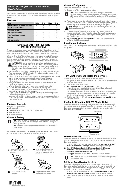
750The Eaton 3S uninterruptible power system (UPS)protects your sensitive electronic equipment from power problems such as power failures,power sags,and power surges.FeaturesModel350VA 450VA 550VA 750VA Battery Backup and Surge Protection Outlets 4445Surge Protection Only Outlets 4445EcoControl Function √User-Replaceable Battery √√√√Phone/Fax/DSL Surge Protection √√√√USB Port√√√Cold Start Capability√√√√IMPORTANT SAFETY INSTRUCTIONSSAVE THESE INSTRUCTIONSThis user's guide contains important instructions that you should follow during installation and maintenance of the UPS and batteries.Please read all instructions before operating the equipment and save this user's guide for future reference.When the Eaton 3S UPS is received,remove and inspect the product for shipping damage.If any damage is found,notify the carrier and your dealer immediately.Keep all shipping contents,including the shipping carton,packing material,and packing slip,in the event that the UPS must be returned to the factory for service.CAUTION Maintenance must be performed by a qualified personnel.Failure to do so could result in an electric shock.Replace battery with an Eaton supplied battery ONLY!Although the UPS may be unplugged from the utility power,hazardous voltage still may be present through the battery.S Place the Eaton 3S UPS indoors in an area that has adequate airflow and is free from excessive dust.DO NOT allow the UPS to be exposed to moisture,rain,excessive heat,or direct sunlight.S Use of the Eaton 3S UPS product in life support applications where failure of this equipment can reasonably be expected to cause failure of life support equipment or to significantly affect its safety or effectiveness is NOT recommended.S Always turn off the UPS and disconnect the input power cord from the wall outlet before replacing the battery.S When replacing the battery,use the same number and type of battery.S DO NOT dispose of the battery in a fire,the battery may explode.S DO NOT open or mutilate the battery.Batteries contain an electrolyte that is toxic and harmful to both the skin and eyes.S Proper disposal of the battery is required.Refer to your local laws/regulations regarding battery recycling/reuse.S Use tools with insulated handles to replace the battery to avoid personal injury.Due to energy hazards,remove wristwatches and jewelry such as rings whenreplacing the battery.Package ContentsVerify the package contents:S Eaton 3S UPSS USB cable (450VA,550VA,and 750VA models only)S This user's guide S Warranty statementConnect BatteryNOTE Check the battery recharge date on the shipping carton label.If the date has passed and the batteries were never recharged,do not use the UPS.Contact your service representative.NOTE If the UPS requires any type of transportation,the internal UPS battery MUST be disconnected.For safety,the UPS is shipped with the battery wires disconnected.The UPS will not run until the wires are connected to the battery terminals.release tab.Slide the battery cover off the UPS.battery wires firmly to the battery terminals;red to positive (+),black to negative (–).Insert the battery back into thecompartment.Slide the battery cover on the UPS until the release tab locks into place.Connect EquipmentTo connect and operate the Eaton 3S UPS:1.Connect the UPS to a grounded power outlet.NOTE Eaton recommends that the battery should be charged for a minimum ofeight hours to ensure full charge before placing the UPS in service.The UPS charges the battery as soon as it is connected to the AC outlet,whether the On/Off button is pressed or not.2.Plug your computer,monitor,or load to be protected into the Battery Backupand Surge Protection outlets.(These outlets provide emergency battery backup power during power outages and protection from surges and spikes.)CAUTION DO NOT plug laser printers or accessory surge strips into the battery backup outlets.3.Plug your peripheral equipment or non-critical loads (printer,scanner,fax,speakers,etc.)into the Surge Protection outlets.(These outlets provide surge and spike protection only,they DO NOT provide battery backup power during a utility power failure).4.450VA,550VA,and 750VA models only.Connect your computer to theUPS using the USB cable provided.Installation PositionsThe UPS can be free-standing or wall-mounted.For safety,do not place the UPS on its right side.Turn On the UPS and Install the SoftwareTo turn the UPS on and install the power management software:1.With your equipment turned off,press the UPS On/Off button.The UPS On/Offbutton illuminates green.2.Turn on the connected equipment.3.450VA,550VA,and 750VA models only.Go to/powerquality to download and install Eaton's Personal Solution-Pac t power management software.The Personal Solution-Pac software establishes communication between your computer and UPS.The software allows you to change default UPS settings and view information about the status of your utility power line.4.Register your Eaton 3S UPS online at /powerquality for anextended warranty.EcoControl Function (750VA Model Only)The EcoControl function is an energy-saving feature that can be enabled through the Personal Solution-Pac software.When the EcoControl function is enabled,the EcoControl outlets automatically power down when the load connected to the Master outlet is turned off.Enable the EcoControl FunctionThe EcoControl function is disabled by default.The Personal Solution-Pac software must be installed before the EcoControl function can be enabled.To enable the EcoControl function:1.From your Microsoft ®Windows ®Start menu,click All Programs >EATON >Personal Solution Pac >Settings .The EATON Settings window opens.2.Go to UPS Settings >EcoControl function >EcoControl functionactivation .The EcoControl function activation panel displays.3.Select EcoControl function activation .4.Click Apply to activate,or click OK to activate and close the window.NOTE When the EcoControl function is activated,do not connect critical applications to the EcoControl outlets.Set the EcoControl Function ThresholdThe default trigger threshold (Medium)ensures the correct operation of theEcoControl function for a typical load consumption on the Master outlet.If the load consumption is outside of the default trigger threshold range,you can modify the threshold.To modify the trigger threshold:1.From your Microsoft WindowsStart menu,click All Programs >EATON >Personal Solution Pac >Settings .The EATON Settings window opens.2.Confirm that the function is activated in the EcoControl function activationpanel.Eaton is a registered trademark and Personal Solution-Pac is a trademark of Eaton Corporation or its subsidiaries and affiliates.Microsoft and Windows are registered trademarks of Microsoft Corporation in the United States and/or other countries.All other trademarks are property of their respective companies.E Copyright 2010Eaton Corporation,Raleigh,NC,USA.All rights reserved.164202102Rev P013.Select EcoControl function detection threshold .The EcoControl functiondetection threshold panel displays.4.If the peripherals connected to the EcoControl outlets do not turn off when theload powered by the Master outlet is turned off or is in standby mode,set the detection threshold value to High .5.If the peripherals connected to the EcoControl outlets turn off when the loadpowered by the Master outlet is working normally,set the detection threshold value to Low .6.Click Apply to activate,or click OK to activate and the close window.7.Restart the load connected to the Master outlet.Indicators1.On/Off ButtonButton that controls power to the UPS and initiates the self-test function.S Press the On/Off button to turn on the UPS.S Press the On/Off button again to turn off the UPS.The UPS performs a self-test for about 5seconds when the UPS is turned on.2.Fault/Warning (Red)LEDIndicates that a fault or warning condition is present.S A flashing red LED indicates that a Site Wiring Fault exists.S A solid illuminating red LED indicates that an internal UPS fault exists,or that the battery should be replaced.3.Surge Protection OutletsOutput receptacles that provide surge and spike protection only.S 350–550VA models have four 5-15R surge protection outlets.S 750VA model has five 5-15R surge protection outlets.4.Battery Backup and Surge Protection OutletsOutput receptacles that provide both backup and surge protection.S 350–550VA models have four 5-15R backup and surge protection outlets.S 750VA model has five 5-15R backup and surge protection outlets.5.Modem/Phone/DSL/Fax Surge Protection PortsA modem or Ethernet data line can be protected against surges by connecting it through the UPS.Connect the device cable between the wall outlet and the UPS,and use a similar cable between the UPS and the device.B Communication Port (450VA,550VA,and 750VA models only)The built-in USB port connects to your computer (with the provided USB cable).The Personal Solution-Pac monitoring and shutdown software can beconfigured to automatically save your files and shut down your computer in the event of a prolonged power outage.Your computer can receive the status of utility power line,utility power failure,on battery,and low battery by contact closure signals that are sent through the USB port.7.Circuit Breaker (resettable)The circuit breaker button protrudes when the overload condition occurs.If the button protrudes,disconnect some of the non-essential equipment and reset the circuit breaker by pressing the button in.8.Input Power CordSix-foot line cord.Replace BatteryTurn the UPS over and press in the release tab.Slide the battery cover offConnect the battery wires firmly to the replacement battery terminals;red topositive (+),black to negative (–).Insert the replacement battery into the battery compartment.Slide the battery cover on the UPS until the release tab locks intoplace.Pull out the battery and disconnect the battery wires.Turn off the UPS and disconnect theUPS from the power source.Service and SupportFor questions and/or problems,please call your local distributor or the EatonCustomer Support Center at one of the following telephone numbers and ask for a UPS technical representative.United States:1.800.356.5737Europe,Middle East,and Africa:+44.17.53.608.700Asia:+852.2830.3030Australia:+61.3.9706.5022Please have the following information ready when you call the Eaton Customer Support Center:Model number,serial number,symptoms of failure or problem,customer return address,and contact information.If repair is required,you will be given a Returned Material Authorization (RMA)Number.This number must appear on the outside of the package and on the Bill of Lading (if applicable).Use the original packaging or request packaging from the Eaton Customer Support Center or distributor.Units damaged in shipment as a result of improper packaging are not covered under warranty.A replacement unit will be shipped,freight prepaid for all units under warranty.For additional information please visit us online at /powerquality .SpecificationsModel 3S3503S4503S5503S750UPS Power350VA /200W450VA /270W550VA /330W750VA /450WInput Voltage Range 96V–138V,adjustable to 75V–144V through Personal Solution-PacInput Frequency50/60Hz (46–70Hz working range)Voltage/Frequency of Battery Backup Outlets in Battery Mode 115V +15%-20%/50–60Hz ±1%Input Protection 10A resettable circuit breaker12A resettable circuit breaker Transfer Time5ms typical Phone /ISDN /ADSL /Ethernet Surge Protection RJ-45Sealed Lead Acid Battery 12V,4.5Ah 12V,4.5Ah12V,5Ah12V,9AhOperating Temperature 0°C to 40°C (32°F to 104°F)Storage Temperature -2.5°C to +55°C (28°F to 131°F)Operating Relative Humidity 0to 85%noncondensingSafety Standards UL 1778ElectromagneticCompatibility Standards FCC Part 15Class BUPS Dimensions (H ×W ×D)335×140×86mm (13.2”×5.5”×3.4”)335×170×86mm (13.2”×6.7”×3.4”)UPS Weight 2.9Kg (6.4lb)4.2Kg (9.3lb)TroubleshootingProblemDiagnosticSolutionThe Fault/Warning LED flashes red immediately after plugging the UPS into a wall outlet.A Site Wiring Fault hasoccurred.The outlet that the UPS is plugged into is not properly grounded or properly wired.Have a qualified electrician correct the wiring.The outlets are not powered.The wall outlet is not powered.Supply power to the wall outlet.The circuit breaker has been tripped by an overload on the UPS output.Reduce the amount of equipment plugged into the UPS and press the circuit breaker in to reset.The On/Off button flashes green and the audio alarm beeps.The UPS frequently operates on battery power because the AC power source is of poor quality.Have the electrical installation checked by a professional or use another wall outlet.The On/Off button flashes green and the audio alarm beeps continuously.The UPS battery backup outlets are overloaded.Disconnect excess equipment connected to the battery backup outlets.AC power is available,but the UPS operates on battery power.The UPS circuit breaker tripped due to an overload on the UPS output.Reduce the amount of equipment plugged into the UPS and press the circuit breaker in to reset.Battery backup outlets are not powered.The On/Off button is not illuminated.Press the On/Off button and verify that it illuminates green.The connected devices are not powered when AC power fails.The devices are connected to the Surge Protection only outlets.Connect the devices to the Battery Backup outlets.The telephone line is disturbed or modem access is not possible.Surge protection on the telephone line is no longer provided.Disconnect the telephone line from the wall outlet and contact your service representative.The Fault/Warning LED illuminates red.The battery has reached the end of its service life.Replace battery.The Fault/Warning LED illuminates red and the audio alarm beeps every 30seconds.A fault has occurred on the UPS.The battery backup outlets are not powered.Contact your service representative.。
FULENT user's guide 3-2
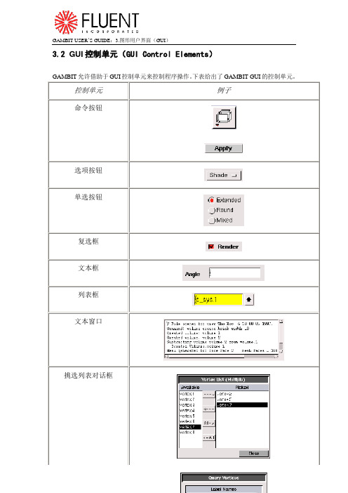
3.2 GUI控制单元(GUI Control Elements)GAMBIT允许借助于GUI控制单元来控制程序操作。
下表给出了GAMBIT GUI的控制单元。
控制单元例子命令按钮选项按钮单选按钮复选框文本框列表框文本窗口挑选列表对话框查询列表对话框滑动条下面部分将对上面提到的每个控制单元的意义和操作进行描述。
3.2.1 命令按钮(Command Buttons)命令按钮用来执行程序操作。
这里有两种类型的命令按钮:工具箱型(toolpad)和对话框型(form)。
下表给出了每种命令按钮的例子。
类型例子工具箱型对话框型工具箱型命令按钮位于Operation工具箱和Global Control工具箱中;对话框型命令按钮位于GAMBIT对话框中(例如,规范对话框)。
要执行任意命令按钮所代表的操作,只需鼠标左击该按钮即可。
工具箱型命令按钮(Toolpad Command Buttons)工具箱型命令按钮用来执行的程序命令包括创建、网格划分、分配区域类型、或者察看模型以及在GUI上各种工作。
一些工具箱型命令按钮会引起直接的操作,另一些则会打开具体的对话框。
每一个工具箱型命令按钮都有一个代表该按钮功能的符号。
任何可以执行多个功能的按钮(多功能命令按钮)在它的左下角都有一个向下的小箭头。
例如,上面所示的Stitch Faces 命令按钮就可以执行如下的功能:●扫描实面●旋转实面●由线框形成实体要执行一个多功能命令按钮上当前显示的符号所代表的命令,鼠标左击按钮即可。
要改变命令按钮的功能,鼠标右击按钮,打开一个可利用的功能的列表,然后用鼠标左击需要的功能项,就把它从列表中选出来了。
对话框型命令按钮(Form Command Buttons)对话框型命令按钮可以用来执行与GAMBIT对话框有关的操作。
每个按钮只有一个名称(例如,Apply、Reset或Close)。
要执行一个对话框型命令按钮上的名称所代表的操作,只需鼠标左击该按钮即可。
VUB-100FM FM Radio Recorder User's Guide
Double-click FMScan.exe to run the software. A screen similar to the following will appear:
System Configuration
COM Port: VUB-100FM’s COM port usage If Windows successfully loaded the VUB-100FM driver, the message “System initialization completed” will be shown in the Operation Log. If Windows could not load the driver then the COM Port setting may be wrong. Check COM port usage in Windows Device Manager. For example, the following shows VUB-100FM using COM4.
Manual Record
Band (MHz): Enter the band to record Set: Apply the band setting and turn on the internal monitoring speaker Record: Start the manual recording Stop: Stop the manual recording and turn off the internal monitoring speaker
HARDWARE PANEL DESCRIPTIONS
SPEAKER: ON/OFF switch for the internal monitoring speaker ANT: Connection to Antenna USB1: Connection to PC via cable USB1 USB2: Connection to PC via cable USB2
- 1、下载文档前请自行甄别文档内容的完整性,平台不提供额外的编辑、内容补充、找答案等附加服务。
- 2、"仅部分预览"的文档,不可在线预览部分如存在完整性等问题,可反馈申请退款(可完整预览的文档不适用该条件!)。
- 3、如文档侵犯您的权益,请联系客服反馈,我们会尽快为您处理(人工客服工作时间:9:00-18:30)。
User's GuideDatalogging Light Meter with PC InterfaceModel 401036WarrantyEXTECH INSTRUMENTS CORPORATION warrants this instrument to be free of defects in parts and workmanship for one year from date of shipment (a six month limited warranty applies to sensors and cables). If it should become necessary to return the instrument for service during or beyond the warranty period, contact the Customer Service Department at (781) 890-7440 ext. 210 for authorization or visit our website for contact information. A Return Authorization (RA) number must be issued before any product is returned to Extech. The sender is responsible for shipping charges, freight, insurance and proper packaging to prevent damage in transit. This warranty does not apply to defects resulting from action of the user such as misuse, improper wiring, operation outside of specification, improper maintenance or repair, or unauthorized modification. Extech specifically disclaims any implied warranties or merchantability or fitness for a specific purpose and will not be liable for any direct, indirect, incidental or consequential damages.Extech's total liability is limited to repair or replacement of the product. The warranty set forth above is inclusive and no other warranty, whether written or oral, is expressed or implied.IntroductionCongratulations on your purchase of the Extech 401036 Datalogging Light Meter. This device measures light intensity to 20,000 Foot-candles (Fc) or Lux. 16,000 measurement readings can be logged by the meter and later transferred to PC using the RS-232 interface. Real-time meter/PC logging is also supported. Careful use of this meter will provide years of reliable service.SpecificationsDisplay 3 ½ digit (2000 count) multifunction LCD displaySensor Silicon Photo-diode meets C.I.E. photopic curve V (λ)Ranges / Resolution 19.99, 199.9, 1999, and 1999 x 10 Fc and LuxAccuracy ± (3% reading + 5 digits)2%Repeatability ±Datalogger memory 16,000 readings max.PC Interface RS-232C Serial Communications at 9600 bpsRange status indication 'OL' is displayed for measurement exceeding published limits Sampling time 2.5 readings per secondPower Supply 9V battery (display includes low battery indicator);50 hour typical battery lifeOperating temperature 32 to 104o F (0 to 40o C)Operating Humidity < 80% RHWeight 9.6 oz. (300g)Dimensions Meter: 5.7 x 2.8 x 1.5" (146 x 70 x 39mm);Probe: 3.4 x 2.4 x 1.1" (87.5 x 60 x 29mm)Accessories Carrying case, Windows TM software, PC Interface cable, &9V batteryMeter Description1. 2000 Count LCD includes LUX, Fc, low battery, MAX, H (hold), & x10 indicators2. ON/OFF key Turns the meter on or off3. Max. Hold key When pressed, the LCDdisplays only the maximum reading 4. Lux/Fc key Press to toggle the displayedunit of measure. The LCD shows the unit 5. Light Sensor (Lens cover not shown)Collects light. Note that a tripod mount is located on the rear of the sensor 6. Range key Press repeatedly to selectdesired range: 20, 200, 2,000, 20,000 7. Data Hold key Press to freeze thedisplayed measurement 8. Record/Erase key Press momentarily tostore one reading; Press and hold for 3 seconds to activate the continuous recording mode. Press again to end recording 9. RS-232 jack Stereo jack for PC to Meterconnection cable 10. Zero adjust Cover the sensor withsupplied lens cap and adjust the zero pot for a 0.0 Fc/LUX displayNote that the battery compartment, tilt stand, and hanging mount are located on the rear of the meterSpectral Sensitivity Curveλ) RelativeSensitivity (%)Wavelength (nm)876910Operation1. Turn the meter ON or OFF with the ON/OFF key.2. Press the Lux/Fc key to select the unit of measure for light intensity.3. With the lens cap completely covering the light sensor, zero the meter by adjusting thescrew on the right side of the meter for an LCD reading of 0.0.4. Remove the lens cap to allow the sensor to collect light.5. Read the light intensity measurement on the LCD.6. For over-range conditions, the ‘OL’ icon will display. Select a higher range by pressingthe Range key until a valid reading replaces the ‘OL’ display.7. For the 20,000 range, multiply the displayed reading by a factor of 10.Data HoldPress the HOLD key to freeze the displayed reading. Press HOLD again to return to the normal operating mode.Maximum (MAX) readingPress the MAX key to display only the highest reading. As higher measurements are made the display updates accordingly. The ‘MAX’ icon appears on the LCD in this mode of operation. To return to normal operation, press the MAX key again and the MAX indicator will extinguish.Range selectionPress the RANGE key to select the appropriate measurement range. Start with the lowest range (20) and work up to higher ranges as needed. If ‘OL’ (overload) is displayed, press the range key until a valid reading is displayed.DataloggerREC/ERASE KeyThe REC/ERASE key is used to record and erase data. Press the REC/ERASE key once to log one reading (REC icon flashes once on the LCD). To automatically datalog readings at programmable intervals (continuous recording mode), press and hold the REC/ERASE key for 3 seconds (REC icon begins flashing repeatedly).Press the REC/ERASE key any time while recording to exit the record mode. When the memory is full (16,000 readings or 255 sets), the LCD will display ‘FULL’ and recording ends. To download and view the stored data, connect the meter to a PC and perform the steps provided in the ‘PC Interface’ section of this manual.To erase stored data, perform these steps:1. With the meter turned off, press and hold the REC/ERASE key.2. Turn the meter on by pressing the ON/OFF key and then immediately release theON/OFF key.3. Continue to hold the REC/ERASE key until ‘del’ flashes 3 times on the LCD. The meterautomatically returns to normal operation after the data are erased.Sampling RateThe sampling rate is the interval of time between logged readings. Note that there are two sampling rate selections for two separate datalogging scenarios described below:1. PC Sampling RateThe PC sampling rate is the rate at which measurements are recorded by the PCwhile the meter is connected to the PC. This is known as real-time recording sincethe readings are being taken by the meter and recorded by the PC at the sametime. Set the rate in the supplied software program as described in the PCSAMPLING paragraph on page 6.2. Datalogger Sampling RateThis is the meter’s internal sampling rate used when the meter is logging readingsremotely in continuous recording mode (disconnected from the PC). The defaultrate is 1 second. Change the rate in software by following the steps on page 6 forSAMPLING TIME with the meter connected to the PC.PC InterfaceConnect the supplied interface cable to the phono jack on the right side of the light meter and to the PC 9-pin COM port.Windows TM SoftwareRefer to separate instructions supplied on the Software Program disk for the operation of the Windows TM Software.Battery ReplacementThe meter uses a 9V battery for its operational power and it has a 50 hour typical life span.Replace the battery when the low battery icon appears on the meter’s LCD display.1. Remove the three (3) Phillips screws on the rear of the meter.2. Open the meter housing and replace the battery3. Close the meter housing and secure the rear screwsCalibration and Repair ServicesExtech offers repair and calibration services for the products we sell. Extech also provides NIST certification for most products. Call the Customer Service Department for information on calibration services available for this product. Extech recommends that annual calibrations be performed to verify meter performance and accuracy.Support line (781) 890-7440Technical support: Extension 200; E-mail: support@Repair & Returns: Extension 210; E-mail: repair@Product specifications subject to change without noticeFor the latest version of this User’s Guide, Software updates, and otherup-to-the-minute product information, visit our website: Extech Instruments Corporation, 285 Bear Hill Rd., Waltham, MA 02451Copyright © 2005 Extech Instruments CorporationAll rights reserved including the right of reproduction in whole or in part in any form.。