手把手教你安装TS3310磁带库
IBM磁带存储TS3XXX用法以及常见问题解决
140MB/s
Generation 1
Generation II
Generation III
Generation IV
generation V
100 GB 15 MB/S
8 FC-1, Ultra II
Full High MP 609M 4 M/S 6 M/S No 384
124 kbpi
200 GB 35 MB/S
•1-4 LTO Ultrium 5 HH Drive Features •HH SAS or Fibre •3-slot I/O
•48 DataCartridge Slots
•Standalone or Rack
•Multi-Path Architecture •LTO Gen 5 Media
•LTO Gen 5/4 Encryption
TS3100 (3573)
T S3200 (3573)
T S3310 (3576)
3 or 4 HH or FH
1 FH or 2 HH 24
3 or 4 HH or FH
2 FH or 4 HH 48
3 or 4 FH
18 403
TS3500 (3584)
3 or 4 FH 192
+20,000
IBM LTO Ultrium 5 HH Product Family
Generation 1 100 GB
Generation 2 200 GB
Generation 3 400 GB
Generation 4 800 GB
Next Generation 5
1.5 TB
15 MB/sec
20 - 40 MB/sec 40 - 80 MB/sec 80-120 MB/sec
Solaris10下通过TSM配置磁带库
Solaris 10下通过TSM配置磁带库实战:Solaris 10下通过TSM配置磁带库IBM Tivoli Storage Manager(以下简称TSM)作为企业级跨平台的数据备份恢复软件,提供全面的存储管理解决方案,专门用来满足客户不断增长的存储需求,使存储管理功能自动化、高效化。
通过TSM灵活的策略管理功能,您可以规定哪些数据需要备份或存档、存储在哪里以及保存多长时间。
强大的TSM 调度特性消除了人工备份和跟踪的需求,促进了存储操作向非高峰时间的调度,从而优化了网络资源和性能。
TSM背景介绍鉴于TSM强大的功能、良好的用户界面,其赢得了众多客户的青睐。
但TSM更多的是用于IBM Aix、Microsoft Windows、Linux、Hp-ux等操作系统,在Sun Solaris平台上的使用相对较少。
目前Sun Solaris平台上大都使用Symantec Veritas 备份管理软件进行数据备份与恢复。
与其他Unix操作系统相比较,Solaris在设备管理方面相对麻烦,主要体现在需要修改设备配置文件、进行LUN-Target的绑定等等。
而且不同的Solaris操作系统版本,对于相同设备的配置方法也有所不同。
除此以外,TSM在Sun Solaris平台上的安装配置除了常规的驱动程序安装外,还需要修改配置文件并在此基础上生成TSM自身可使用的设备文件。
因此,给TSM的配置带来了诸多的不便,也给安装者提出了更好的要求。
LAN-Free安装实例下面以一个LAN-Free的示例来说明TSM在Solaris 10平台上的配置过程。
在Solaris平台下安装TSM的关键也在于正确生成TSM 所需要的设备文件,因此本文的重点在于如何生成TSM所需要的设备文件,也没有就TSM的具体安装步骤作描述。
环境描述:TSM服务器:SunFire v490OS Level:Solaris 10TSM Server:5.3.3磁带库:STK L700E,机械臂通过SCSI与TSM服务器相连,驱动器则通过光纤交换机与TSM服务器及八台备份客户端(Sun服务器)相连.配置步骤:确认HBA卡类型1、确认Host Bus Adapter卡(以下简称HBA卡)类型在Sun主机上可使用的HBA卡目前主要有两种,一种是Qlogic公司的HBA卡,另一种是Sun自身的HBA卡。
NBU磁带库备份系统的安装步骤
软件安装软件安装主要包括MasterServer、MediaServer、软件的安装。
在备份系统中,选择hp做为MasterServer,同时充当MediaServer的角色。
为便于管理,确定MasterServer作备份系统的Global Database Host,用于存放所有的配置和备份信息。
下面逐一介绍每一种软件的安装过程,软件安装列表见附件三。
2.4.1 NetBackup DataCenter MasterServer Installition安装前作如下准备工作,在MediaServer安装时也要作同样的准备:·连接硬件所有MediaServer/MasterServer以及带库、磁带机均连接到一台SAN光纤交换机。
·硬件识别在安装软件之前,要保证系统能够识别磁带机和机械手(只需MasterServer识别机械手)#ioscan –fnC tape·系统空间安装MasterServer之前,确保系统空间大小:RAM ≥512Mb安装目录可用空间≥64Mb/tmp可用空间≥32Mb·系统配置在备份环境中每台主机都要修改/etc/hosts文件,提供hostname/ip的解析。
在MasterServer端的/etc/hosts文件中增加如下内容:安装步骤如下:step1: pfs_mountd &pfsd 6&pfs_mount -o xlat=unix /dev/dsk/c3t2d0 /cdromstep2:切换到光盘目录#cd /cdromstep3:执行安装脚本#./installVERITAS Installation ScriptCopyright 1993 - 2002 VERITAS Software Corporation, All Rights Reserved.Installation Options1 NetBackup2 NetBackup Client Software3 NetBackup Client Java Softwareq To quit from this scriptChoose an option [default: q]: 1/*选则1,安装Server,同时也安装mediaserver 软件The NetBackup and Media Manager software is built for use on hp hardware.Do you want to install NetBackup and Media Manager files? (y/n) [y] yNetBackup is normally installed in /usr/openv/netbackup.Is it OK to install in /usr/openv/netbackup? (y/n) [y] y/*确定Netbackup安装目录Media Manager is normally installed in /usr/openv/volmgr.Is it OK to install in /usr/openv/volmgr? (y/n) [y] y/*确定MediaManager安装目录The hp clients will be loaded.Do you want to load any other NetBackup clients onto the server? (y/n) [y] n/*确定是否安装其他client,server本身已包含client软件,所以选择“n”……Enter license key: /*输入NetBackup DataCenter Base license AJX6-OPWD-IC6K-3N36-383P-NCNP-PNNR-PPP:NetBackup DataCenter Base product with the following features enabled: Core Frozen Image ServicesOpen Transaction Managerhas been registered.All additional keys should be added at this time.Do you want to add additional license keys now? (y/n) [y] y /*输入其他相关license,也可在安装完软件后再输入其他licenseLicense Key Utility-------------------A) Add a License KeyD) Delete a License KeyF) List Active License KeysL) List Registered License KeysH) Helpq) Quit License Key UtilityEnter a letter:Installing NetBackup DataCenter version: 4.5GAIs backupserver the master server? (y/n) [y] y /*设置主机backupserver作masterserver Do you have any media (slave) servers? (y/n) [n] y/*设置其他主机作mediaserver Enter the fully qualified name of a media (slave) server (q to quit)? SUNV880_AEnter the fully qualified name of a media (slave) server (q to quit)? SUNV880_B Enter the fully qualified name of a media (slave) server (q to quit)? qChecking for a bpcd entry in /etc/inetd.conf: Adding bpcd entry.Original /etc/inetd.conf saved as /etc/inetd.conf.NBU_061103.10:25:08.Checking for a vnetd entry in /etc/inetd.conf: Adding vnetd entry.Checking for a vopied entry in /etc/inetd.conf: Adding vopied entry.Checking for a bpjava-msvc entry in /etc/inetd.conf: Adding bpjava-msvc entry.Checking /etc/services for the needed NetBackup and Media Manager services.Copying original /etc/services file to /etc/services.NBU_061103.10:31:32/etc/services to update NetBackup and Media Manager services./etc/services will be updated to add the following entries for NetBackup/Media Manager.bprd 13720/tcp bprdbpcd 13782/tcp bpcdbpdbm 13721/tcp bpdbmvnetd 13724/tcp vnetdvopied 13783/tcp vopiedbpjobd 13723/tcp bpjobdnbdbd 13784/tcp nbdbdvisd 9284/tcp visdbpjava-msvc 13722/tcp bpjava-msvcvmd 13701/tcp vmdacsd 13702/tcp acsdtl8cd 13705/tcp tl8cdtldcd 13711/tcp tldcdts8d 13709/tcp ts8dodld 13706/tcp odldtl4d 13713/tcp tl4dtsdd 13714/tcp tsddtshd 13715/tcp tshdtlmd 13716/tcp tlmdtlhcd 13717/tcp tlhcdlmfcd 13718/tcp lmfcdrsmd 13719/tcp rsmdTo change these entries modify the file /tmp/services.ov_edited.24848and enter <RETURN> when ready to continue:/etc/services has been updated to contain NetBackup and Media Manager services.To make NetBackup and Media Manager start up automatically when the system is restarted, the rc.veritas.aix script found in /usr/openv/netbackup/bin/goodies has been placed in the /etc directory, you must modify /etc/inittab to include it.……Enter which host will store global device information.(default: backupserver): backupserver /*设置masterserver 作全局设备信息中心To be able to install the client software the NetBackupprocesses need to be started. Do you want to start theNetBackup processes so client software can be installed? (y/n) [y] yStarting the NetBackup database manager process (bpdbm)./*启动bpdbm进程以装载client软件Do you want to create policy and schedule examples that you can view or usewhen you are configuring your own policies and schedules? (y/n) [y]n/*确定是否安装策略模板Client database indexing reduces the search time when restoringclient files, but it takes about 2% more disk space.Do you want to index the client database files? (y/n) [y] y/*确定是否采用client index 文件The default index level is 9 levels. Use the default? (y/n) [y] y /*确定 client index levelRunning index_clients process in background mode.Output from the process will be written to /tmp/index_clients.output.Do you want to start the Media Manager device daemon processes? (y/n) [y] y Starting the Media Manager device daemon processes./*确定是否启动MediaManager 进程Do you want to start the NetBackup bprd process sobackups and restores can be initiated? (y/n) [y] yStarting the NetBackup request daemon process (bprd)./*确定是否启动Netbackup 监听进程Done executing NB.instStep4 :确认安装成功#/usr/openv/netbackup/bin/goodies/bp.kill_all关闭所有已启动的NBU进程#/usr/openv/netbackup/bin/goodies/netbackup start启动NBU进程#/usr/openv/netbackup/bin/bpps –a查看NBU进程#/usr/openv/netbackup/bin/jnbSA&启动NBU的java管理界面至此,MasterServer软件安装完毕。
磁带机维护手册

IBM磁带机及磁带库日常工作手册第一章:日常基本问题的处理 (3)磁带卡在磁带机里不能够弹出: (3)磁带有关的故障: (4)磁带机读/写有关的故障: (5)磁带机和主机连接的问题: (5)第二章:磁带机(库)相关的信息: (8)LTO和3592磁带机最新的微码信息: (8)LTO磁带机的数字信息(SCD code) (8)3580磁带机(TS22x0、TS23x0) (9)3581磁带库(L13、H13、L17、H17、L23、L23) (9)3581 2U磁带库(L28、L38、L3H、F28、F38、F3H) (10)3583磁带库 (11)3584磁带库 (12)3573 LTO磁带库(TS3100、TS3200) (13)3576 LTO 磁带库(TS3310) (13)3590 磁带驱动器(Bxx、Exx、Hxx) (14)第三章:相关数据的收集 (17)附录A:LTO和3592磁带机微码详细信息。
(18)附录B:LTO的SCD code详细说明。
(45)第一章:日常基本问题的处理磁带卡在磁带机里不能够弹出:1.在磁带使用之前检查磁带引导针的位置:在新磁带使用之前,应该检查所有LTO或3592磁带的引导针。
确保它在正确的位置。
如果发现其位置不正确,应该将其调整倒正确的位置(如下图)。
可以使用人工卷带工具(P/N LTO=08L9129 3592=18P888)来调整。
具体操作步骤,可以参照《TS2340 3580 L43S43 Setup Operator Service Guide>> GC27-2103中的第4章的:Using Ultrium Media --Repositioning or Reattaching a Leader Pin.。
<=== 正确的位置2.检查是否主机曾经发过“PREVENT MEDIUM REMOV AL”的命令这个命令通常是由主机端的某些应用程序发出的。
TS3310硬件介绍-前面板组件
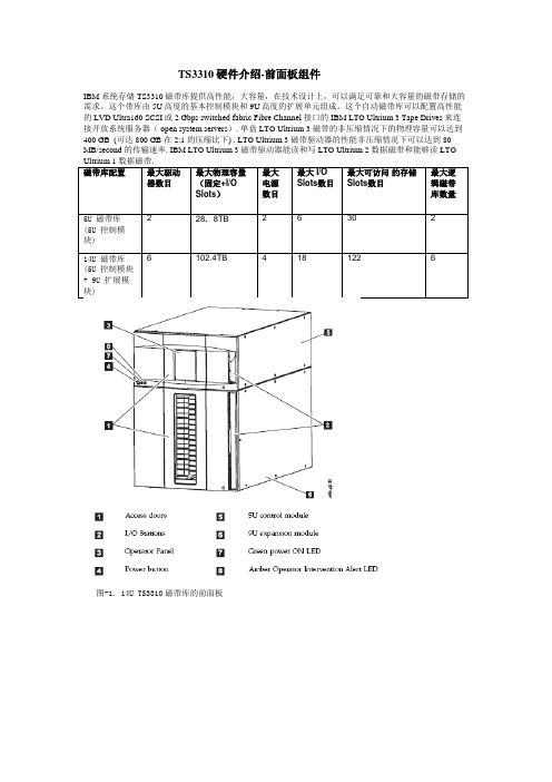
TS3310硬件介绍-前面板组件IBM 系统存储 TS3310磁带库提供高性能,大容量,在技术设计上,可以满足可靠和大容量的磁带存储的需求。
这个带库由5U高度的基本控制模块和9U高度的扩展单元组成。
这个自动磁带库可以配置高性能的LVD Ultra160 SCSI或2 Gbps switched fabric Fibre Channel 接口的 IBM LTO Ultrium 3 Tape Drives来连接开放系统服务器( open system servers). 单盘LTO Ultrium 3 磁带的非压缩情况下的物理容量可以达到400 GB (可达800 GB 在 2:1 的压缩比下) , LTO Ultrium 3 磁带驱动器的性能非压缩情况下可以达到 80 MB/second 的传输速率. IBM LTO Ultrium 3 磁带驱动器能读和写 LTO Ultrium 2 数据磁带和能够读 LTO 块)前面板组件:TS3310磁带库的前面板主要包含下列组件:控制模块扩展模块I/O StationAccess Door操作面板(Operator Panel )电源按钮(Power Button)前面板指示灯(LEDs )控制模块所有的带库配置都必须包括控制模块 (见图-1上的5 ). 控制模块包括机械臂(robotics), 带库控制刀片(library control blade (LCB)), 和触摸屏,除此之外,控制模块还包含 I/O station slots, 固定的存储 slots, 磁带驱动器(tape drives), 和至少一个电源. 控制模块可以配置一个或两个电源,但最少要包含一个电源。
控制模块的高度是5U,包含36个slots,其中有30个存储slots和6个I/O station slots,可以最多配置2个LTO 第三代磁带驱动器。
扩展模块扩展模块 (见图-1上的6) 是一个连接到控制模块下的一个扩展模块。
磁带机安装文档
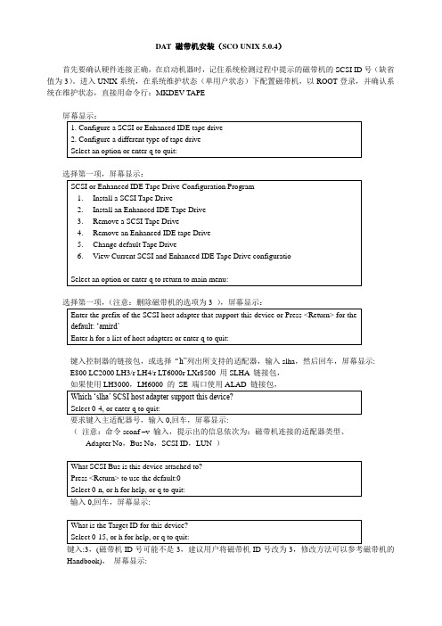
DAT 磁带机安装(SCO UNIX 5.0.4)首先要确认硬件连接正确,在启动机器时,记住系统检测过程中提示的磁带机的SCSI ID号(缺省值为3)。
进入UNIX系统,在系统维护状态(单用户状态)下配置磁带机,以ROOT登录,并确认系统在维护状态,直接用命令行:MKDEV TAPE屏幕显示:键入控制器的链接包,或选择“h”列出所支持的适配器,输入slha,然后回车,屏幕显示:E800 LC2000 LH3/r LH4/r LT6000r LXr8500 用SLHA 链接包,如果使用LH3000,LH6000 的SE 端口使用ALAD 链接包,要求键入主适配器号,输入0,回车,屏幕显示:(注意:命令sconf –v 输入,提示出的信息依次为:磁带机连接的适配器类型、Adapter No,Bus No,SCSI ID,LUN )Handbook),屏幕显示:键入HPTape ,屏幕显示:键入Enter,屏幕显示:键入y,屏幕显示:键入y ,安装完毕,重新引导系统,即可使用磁带机。
检查磁带机的安装方法一:可以通过tape status、tape rewind命令检查磁带机是否正确配置:方法二:在维护状态键入MKDEV TAPE,屏幕显示:常用的磁带机读写命令1)读命令:tar tvf /dev/rct0回车后,屏幕滚动显示磁带中备份的内容和备份时间。
2)写命令:tar cvf /dev/rct0 directory _name or filename回车后,屏幕滚动显示备份内容,比如:备份Var 文件夹,回车后,屏幕滚动显示a var/scohttp/logs symbolic link to /var/opt/K/SCO/Unix/5.0.5Eb/var/scohttp/logsa ……………….a………………表示V ar 文件夹中的子文件夹得到备份命令完成后,回到提示符状态3)恢复命令:tar xvf /dev/rct04)擦除磁带内容:tape erase (键入命令后,命令提示符闪烁,同时磁带机灯闪烁),这个命令需要用很长时间,用户需要多等待,以DLT1 磁带机为例,屏幕显示:%Stp-0 - - Vendor = BNCHMARK Product = DLT1_还可以通过两种种方式进入硬件/核心管理,添加磁带机。
IBM 磁带存储TS3XXX用法以及常见问题解决

TS2900连接方式 连
TS2900磁带自动装入器,
只支持SAS驱动器 (LTO3,LTO4)
1. 以太网线 2. SAS连接线 3. 电源线
TS3100/TS3200磁带驱动器类型与连接 磁
SCSI接 口 驱 动 器 , 无 接 “ WRAP”标 识 终 结 器 标
FC接 口 驱 动 器 , 每 驱 接 动 器 只 有 一 个 可 用 FC 端口
IBM存储售后主要问题,Session 3: 存 : IBM 磁带存储 TS2900/TS3100/TS3200/TS3310用法 用 及常见问题解决
Innovation that matters
Tian XiaoLu Techline Storage Team
Topic
IBM LTO 磁带库产品简介 磁带库初始化安装 IBM LTO磁带库管理/使用以及配置 磁 使 如何定义清洁槽和使用清洁功能 各操作系统下驱动程序的下载以及安装 诊断工具简介 :TapeUtil/NTUtil/ITDT LTO磁带库 常见问题以及解决 方法 磁
1. 在 液 晶 面 板 主 菜 单 项 中 选 择 : Unlock I/ O Station 2. 在 I/O Station里 放 入 数 据 带 . 里
放 TS3200/TS3100 如 何通 过I/O Slot放 磁带
1.通 过 液 晶 面 板 菜 单 项 设 置 : Control通 >Open I/O Station 2. 在 I/O Station里 放 入 数 据 带 . 里
放 TS3310 如何通过I/O Slot放 磁带
1. 查 看 逻 辑 带 库 可 用 的 storage slots , 通 过 web菜 单 选 项 Monitor System-> 菜 Library Map. 2. 在 I/O Station里 放 入 数 据 带 . 里 3. 从 液 晶 面 板 菜 单 项 : Operations >Insert Media 或 从 Web 管 理 界 面 : Manage Cartridges->I/O Station
昆腾磁带库换磁带教程
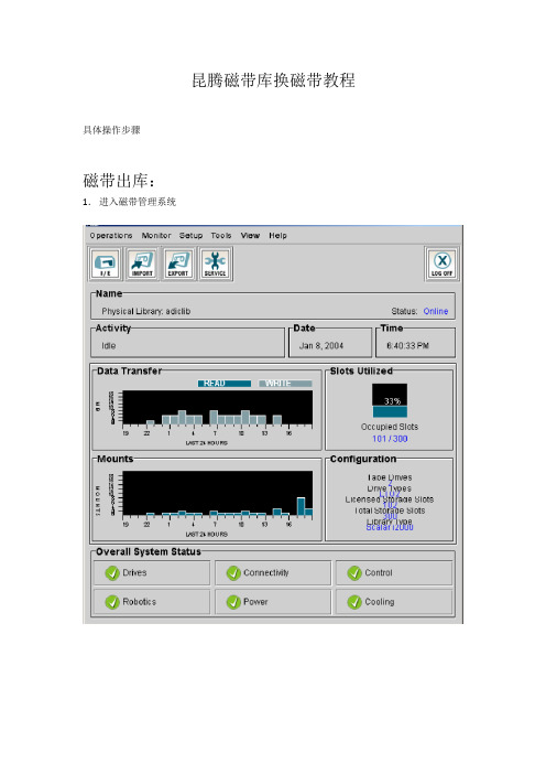
昆腾磁带库换磁带教程具体操作步骤
磁带出库:
1.进入磁带管理系统
2.先将控制界面改为partition
3.点击Operations->Change Mode
4.更改mode 为offline
5.然后选择Operatations->export,在弹出界面中选择欲弹出的磁带
6.点击OK,机械臂将磁带抓到IE 中,磁带后出现exported 字样
7.点击Cancel,到磁带库中打开IE 门便可取出磁带。
磁带入库:
8. 放入IE,关上IE 门,选择Operations->import
9.点击import,系统会自动将你的磁带放入编号最小的空槽位。
移动磁带:
10. 点击Operations->Move Media
11. 选择欲移动的磁带和目的槽位,点击OK。
系统出现移动信息:
12.并将磁带移动到指定槽位,完成后回到Move Media 界面。
13. 点击Cancel 离开。
SM3310 通用端子模块使用说明书(双排端子)
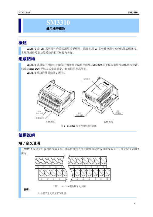
*FQ+、FQ- 为转速信号的正负输入端; *SPEED 为转速大小的电压信号输出正端,FGND 为输入模块的现场信号的公共地端; *OIL-TRIP+、OIL-TRIP- 为油开关跳闸信号的正负输入端; *FMON+、FMON- 为投、切一次调频信号的正负输出端; *NO110A+、NO110A- 为第一个超速 110%报警信号的输出端,常开触点,闭合时表示有报警; *NO110B+、NO110B- 为第二个超速 110%报警信号的输出端,常开触点,闭合时表示有报警; *NO103A+、NO103A- 为第一个超速 103%报警信号的输出端,常开触点,闭合时表示有报警; *NO103B+、NO103B- 为第二个超速 103%报警信号的输出端,常开触点,闭合时表示有报警; * Bn(n=1~16)、NC 不接线。 *VC、GND 为 24V 测试点,实际应用中禁止接线。
SM3310 通用端子模块可与多种 I/O 模块配合使用,构成完整的 I/O 处理单元,实现与现场设备的连 接。具体配置连接及接线说明如下: 配置 SM410 与现场设备连接 现场信号线直接连接到 SM3310 通用端子模块的双列端子上,每路采用两根导线(屏蔽电缆)连 接到对应的端子上,接线端子号与对应通道号见表 1 所示,接线示意图如图 3 所示。
左侧视图 图1 SM3310 端子模块外观示意图
右侧视图
使用说明
端子定义说明
SM3310 模块采用双列接线端子座, 现场信号线直接连接到模块的双列接线端子上, 端子定义如图 2 所示。
图2 说明:
SM3310 模块端子定义图
* 各端子定义详见下节说明。
1
HOLLiAS
SM3310
i40磁带库安装步骤

Quantum I40/I80磁带库安装及维护实施方案一Quantum Scalar i40 Library(FC接口)安装步骤1.磁带库安装前的准备工作(1)准备场地请用户决定磁带库的放置位置,是直接放置在地上,还是安装在机架上。
如果安装到机架上,请尽量安装到机架的底部,保证整个机架的稳定。
(2)准备电源Quantum Scalar i40的电源要求为220V/10A请用户尽早准备。
(3)准备管理接口Quantum Scalar i40磁带库管理接口是一个RJ45接口,用户可以通过浏览器对磁带库进行管理。
(4)管理工具用户及口令磁带库的用户为admin,口令为password2.具体安装步骤第一步验货,拆下外包装,并将磁带库放到指定位置,上机架有特殊套件。
第二步将磁带库固定,保持水平。
第三步将位于设备顶部的用于固定机械臂装置取出,机械手可以移动。
如下图所示:第四步将磁带机装入磁带库,磁带机槽位位置如下图所示:半高磁带机占1个槽位位置,全高磁带机需占用2个槽位位置第五步连接光纤到每个磁带机上,将光纤与光纤交换机进行连接,或直连到主机,将通信网线连接安装到指定位置。
第六步连接电缆,分别打开电源模块上开关和前面板开关。
上电进行自检测试,如果没有报错说明磁带库安装正常。
如果报错可以通过控制面板对磁带库进行检测。
第七步运行磁带库配置向导,特别注意需要指定磁带库IP地址和选定远程控制。
须注意:时区设置无法通过操作面板进行更改,只能通过远程管理页面修改。
I/E导入导出槽的设置为右侧抽屉的第一列。
第八步使用带有标签的磁带对磁带库进行检测,内容,1.磁带入库操作,通过面板将磁带防到磁带槽位上。
2.对磁带库进行自检测试。
3.做不同位置的移动磁带的操作。
第九步将所有磁带贴上标签,然后入库。
(磁带带标图示)第十步再次确认电缆连接和光纤连接。
第十一步到应用主机上确认主机与磁带库的连通性,确保在主机设备管理器中识别到磁带库设备。
在Linux上进行虚拟磁带库安装
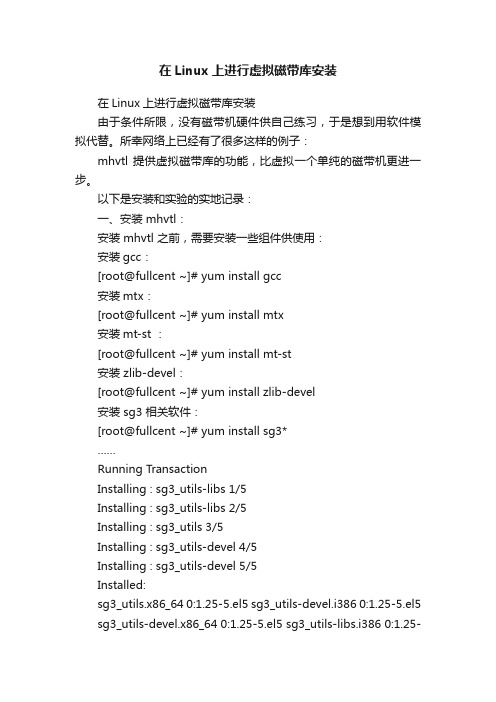
在Linux上进行虚拟磁带库安装在Linux上进行虚拟磁带库安装由于条件所限,没有磁带机硬件供自己练习,于是想到用软件模拟代替。
所幸网络上已经有了很多这样的例子:mhvtl 提供虚拟磁带库的功能,比虚拟一个单纯的磁带机更进一步。
以下是安装和实验的实地记录:一、安装 mhvtl:安装 mhvtl 之前,需要安装一些组件供使用:安装gcc:[root@fullcent ~]# yum install gcc安装mtx:[root@fullcent ~]# yum install mtx安装mt-st :[root@fullcent ~]# yum install mt-st安装 zlib-devel:[root@fullcent ~]# yum install zlib-devel安装 sg3 相关软件:[root@fullcent ~]# yum install sg3*……Running TransactionInstalling : sg3_utils-libs 1/5Installing : sg3_utils-libs 2/5Installing : sg3_utils 3/5Installing : sg3_utils-devel 4/5Installing : sg3_utils-devel 5/5Installed:sg3_utils.x86_64 0:1.25-5.el5 sg3_utils-devel.i386 0:1.25-5.el5 sg3_utils-devel.x86_64 0:1.25-5.el5 sg3_utils-libs.i386 0:1.25-5.el5sg3_utils-libs.x86_64 0:1.25-5.el5Complete![root@fullcent ~]#安装 lsscsi :[root@fullcent ~]# yum install lsscsi安装lzo :[root@fullcent soft]# wget /doc/e0ecb563a45177232f60a2d7.html/opensource/lzo/download/lzo-2.06.tar.gz[root@fullcent soft]# tar -zxvf lzo-2.06.tar.gz[root@fullcent soft]# cd lzo-2.06[*********************]#./configure[*********************]#make&&makeinstall安装 linux kernel :[root@fullcent ~]# yum install kernel-devel创建名为 vtl 的用户:[root@fullcent ~]# useradd vtl[root@fullcent ~]# passwd vtlChanging password for user vtl.New UNIX password:BAD PASSWORD: it is WAY too shortRetype new UNIX password:passwd: all authentication tokens updated successfully.[root@fullcent ~]#创建用于 mhvtl 的目录:[root@fullcent ~]# mkdir /opt/mhvtl[root@fullcent ~]# mkdir /etc/mhvtl[root@fullcent ~]# chown -Rf vtl:vtl /opt/mhvtl[root@fullcent ~]# chown -Rf vtl:vtl /etc/mhvtl[root@fullcent ~]#然后,开始下载 mhvtl 安装包:用如下的地址:https:///doc/e0ecb563a45177232f60a2d7.h tml /site/linuxvtl2/home#mhvtl-download进行解压缩:[root@fullcent soft]# tar -zxvf mhvtl-2013-01-31.tgz进入解压后的目录,进行安装:[**********************]#makedistclean[**********************]#cdkernel[root@fullcent kernel]# make[root@fullcent kernel]# make install[**********************]#cd../[**********************]#pwd/soft/mhvtl-1.4[**********************]#make[**********************]#makeinstall二、使用 mhvtl服务:安装完毕,启动服务:[**********************]#servicemhvtlCould not locate library config file: /etc/mhvtl/library_contents.10Creating a default onePlease stop mhvtl & edit /etc/mhvtl/library_contents.10 to suit your requirementsCould not locate library config file: /etc/mhvtl/library_contents.30Creating a default onePlease stop mhvtl & edit /etc/mhvtl/library_contents.30 to suit your requirementsUsage: /etc/init.d/mhvtl {start|stop|shutdown}可以看到,已经建立了两个配置文件:library_contents.10 和library_contents.30[**********************]#servicemhvtlstartvtllibrary process PID is 3827vtllibrary process PID is 3830[**********************]#ps-ef|grep3827vtl 3827 1 0 10:58 ? 00:00:00 vtllibrary -q 10 -vroot 4320 2944 0 10:58 pts/1 00:00:00 grep 3827[**********************]#ps-ef|grep3830vtl 3830 1 0 10:58 ? 00:00:00 vtllibrary -q 30 -vroot 4322 2944 0 10:58 pts/1 00:00:00 grep 3830[**********************]#对文件状况进行查看:[root@fullcent /]# ls /etc/mhvtl/device.conf library_contents.10 library_contents.30 mhvtl.conf[root@fullcent /]# ls /opt/mhvtl/CLN101L4 E01007L4 E01016L4 F01034L5 G03004TA G03013TA G03022TA G03031TACLN102L5 E01008L4 E01017L4 F01035L5 G03005TA G03014TA G03023TA G03032TACLN303TA E01009L4 E01018L4 F01036L5 G03006TA G03015TA G03024TA G03033TAE01001L4 E01010L4 E01019L4 F01037L5 G03007TA G03016TA G03025TA G03034TAE01002L4 E01011L4 E01020L4 F01038L5 G03008TA G03017TA G03026TA G03035TAE01003L4 E01012L4 F01030L5 F01039L5 G03009TA G03018TA G03027TA G03036TAE01004L4 E01013L4 F01031L5 G03001TA G03010TA G03019TA G03028TA G03037TAE01005L4 E01014L4 F01032L5 G03002TA G03011TA G03020TA G03029TA G03038TAE01006L4 E01015L4 F01033L5 G03003TA G03012TA G03021TA G03030TA G03039TA[root@fullcent /]#基本上,/etc/mhvtl 是放置配置文件的地方,/opt/mhvtl 是放置模拟磁带的文件的地方[root@fullcent /]# cat /etc/mhvtl/mhvtl.conf# Home directory for config file(s)MHVTL_CONFIG_PATH=/etc/mhvtl# Default media capacity (500 M)CAPACITY=500# Set default verbosity [0|1|2|3]VERBOSE=1# Set kernel module debuging [0|1]VTL_DEBUG=0[root@fullcent /]#用 lsscsi 命令查看 scsi 设备的状态:并且对比一下,mhvtl 服务启动前后,lsscsi的结果:这是磁带库启动中的状态:[root@fullcent /]# lsscsi -g[0:0:0:0] disk ATA VBOX HARDDISK 1.0 /dev/sda /dev/sg0[1:0:0:0] mediumx STK L700 0104 - /dev/sg9[1:0:1:0] tape IBM ULT3580-TD5 0104 /dev/st0 /dev/sg1[1:0:2:0] tape IBM ULT3580-TD5 0104 /dev/st1 /dev/sg2[1:0:3:0] tape IBM ULT3580-TD4 0104 /dev/st2 /dev/sg3[1:0:4:0] tape IBM ULT3580-TD4 0104 /dev/st3 /dev/sg4[1:0:8:0] mediumx STK L80 0104 - /dev/sg10[1:0:9:0] tape STK T10000B 0104 /dev/st4 /dev/sg5[1:0:10:0] tape STK T10000B 0104 /dev/st5 /dev/sg6[1:0:11:0] tape STK T10000B 0104 /dev/st6 /dev/sg7[1:0:12:0] tape STK T10000B 0104 /dev/st7 /dev/sg8[root@fullcent /]#[root@fullcent /]# lsscsi -l[0:0:0:0] disk ATA VBOX HARDDISK 1.0 /dev/sdastate=running queue_depth=31 scsi_level=6 type=0 device_blocked=0 timeout=60[1:0:0:0] mediumx STK L700 0104 -state=running queue_depth=32 scsi_level=6 type=8 device_blocked=0 timeout=0[1:0:1:0] tape IBM ULT3580-TD5 0104 /dev/st0state=running queue_depth=32 scsi_level=6 type=1 device_blocked=0 timeout=900[1:0:2:0] tape IBM ULT3580-TD5 0104 /dev/st1state=running queue_depth=32 scsi_level=6 type=1 device_blocked=0 timeout=900[1:0:3:0] tape IBM ULT3580-TD4 0104 /dev/st2state=running queue_depth=32 scsi_level=6 type=1 device_blocked=0 timeout=900[1:0:4:0] tape IBM ULT3580-TD4 0104 /dev/st3state=running queue_depth=32 scsi_level=6 type=1 device_blocked=0 timeout=900[1:0:8:0] mediumx STK L80 0104 -state=running queue_depth=32 scsi_level=6 type=8 device_blocked=0 timeout=0 [1:0:9:0] tape STK T10000B 0104 /dev/st4state=running queue_depth=32 scsi_level=6 type=1device_blocked=0 timeout=900 [1:0:10:0] tape STK T10000B 0104 /dev/st5state=running queue_depth=32 scsi_level=6 type=1 device_blocked=0 timeout=900 [1:0:11:0] tape STK T10000B 0104 /dev/st6state=running queue_depth=32 scsi_level=6 type=1 device_blocked=0 timeout=900 [1:0:12:0] tape STK T10000B 0104 /dev/st7state=running queue_depth=32 scsi_level=6 type=1 device_blocked=0 timeout=900 [root@fullcent /]#这是停止 mhvtl 后的状态:[root@fullcent mhvtl]# service mhvtl stopshutdown of mhvtlSending exit to 11Sending exit to 12Sending exit to 13Sending exit to 14Sending exit to 31Sending exit to 32Sending exit to 33Sending exit to 34Sending exit to 10Sending exit to 30[root@fullcent mhvtl]#[root@fullcent mhvtl]# lsscsi[0:0:0:0] disk ATA VBOX HARDDISK 1.0 /dev/sda[root@fullcent mhvtl]# lsscsi -g[0:0:0:0] disk ATA VBOX HARDDISK 1.0 /dev/sda /dev/sg0[root@fullcent mhvtl]# lsscsi -l[0:0:0:0] disk ATA VBOX HARDDISK 1.0 /dev/sdastate=running queue_depth=31 scsi_level=6 type=0 device_blocked=0 timeout=60[root@fullcent mhvtl]#由上面可以看到:/dev/sg1 - /dev/sg10 均由 mhvtl 模拟出来。
ibm TS3310带库安装配置手册
TS3310安装手册
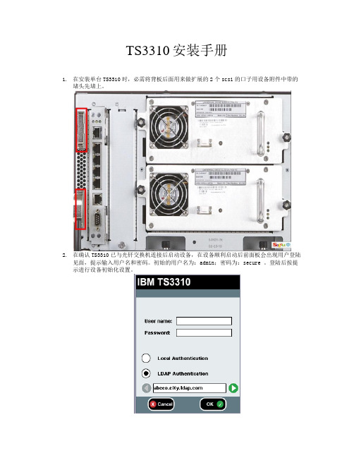
1.在安装单台TS3310时,必需将背板后面用来做扩展的2个scsi的口子用设备附件中带的
堵头先堵上。
2.在确认TS3310已与光钎交换机连接后启动设备,在设备顺利启动后前面板会出现用户登陆
见面,提示输入用户名和密码。
初始的用户名为:admin;密码为:secure 。
登陆后按提示进行设备初始化设置。
3.在进行完TS3310设备初始化设置后,确认服务器是否于光钎交换器正常连接。
将需要连接
设备的服务器开启,并用带有管理员权限的帐号登陆。
安装3580的scsi驱动以及机械臂的驱动。
在“我的电脑”上单击右键;在“管理”中选“设备管理器”,在“设备管理”
中打开“未知设备”,
4.在“IBM Ult3580-TD1 XXXXXXX”上单击右键;在“属性”中选“重新安装驱动程序”或
“更新驱动程序”。
在下个窗口选择“搜索合适的驱动程序”/“指定一个位置”
在下面的窗口输入磁带机驱动的文件夹
(驱动在ftp:///storage/devdrvr/Windows/2003中有下载)
当驱动程序被找到后,系统将提示下面的窗口。
选择下一步我们会得到安装结束的提示:
这样3580的SCSI的驱动就顺利安装完成了,与以前安装3580scsi驱动同样的步骤将机械臂的驱动一起安装完后在设备管理器中会看见设备管理器中如下设备“Changer Bus Enumerator”
这样TS3310便顺利安装到了服务器上。
TS带库安装全攻略

T S带库安装全攻略The Standardization Office was revised on the afternoon of December 13, 2020TS3310带库安装全攻略这次安装的带库包括:3576-L5B(控制模块,简称CM),3576-E9U(扩展模块,简称EM)也叫I/O station。
如果只有一个L5B,那安装起来非常简单,加上一个EM(最多可以带4个EM),安装过程就要注意以下几点:一、拆内置包装物1. 前面板组件展示1 存取口2 电源按钮3 绿色供电(液晶指示灯)4 琥珀色操作员干预警报指示灯5 操作员面板(触摸式)6 5U控制模块7 I/O站8 9U扩展模块注:一个CM+EM可以把CM放上面,或放下面都可以,按个人喜好。
但一定要注意顶板和底板位置。
不管先前顶板原安装哪里,谁放在上面顶板就要盖在上面,反之底板也一样。
这个是来控制机械臂的活动范围。
2. 后面板组件展示1 控制模块(L5B)2 扩展模块(E9U)3 控制模块磁带机(显示FC磁带机)4 扩展模块磁带机5 电源控制器6 控制模块与扩展模块的连接线7 客户用网络端口(4端口提供)8 WEB方式管理磁带库接口(RJ45)注:随机有两个堵头,大约位置在8那里和最左下角位置,切记一定要安装上在开箱时,首先把CM的顶板打开,里面会有固定机械臂(PICKER)的纸板和卡扣,还有一些黄色标志的固定条(打开机器时都会看到),把这些统统拿掉。
不然加电时会影响到机械臂的运动。
二、机械臂的一些装置机械臂锁扣装置,如果CM是放在上面,安装时要把该装置打开,也就是图示的样子。
注意全部安装完毕后,把该装置放回到里面,这样机械臂就可以上下滑动了这叫gear rack(齿轮装置滑轨)也就是picker移动的轨道。
注意:如果有EM的话,一定要调整此位置,不然系统自检不会通过。
我是看了N次的install guide,可惜总不得要领。
IBM TS磁带库操作指南

74
磁带库操作指南-Win
主机配置-LTO带库与win服务器驱动安装
Double click on install_exclusive.exe or install_nonexclusive.exe to start the drivers installation or use the command line options as follows: install_exclusive [-c|-t] [-d] [-s] [-h] [-r] or install_nonexclusive [-c|-t] [-d] [-s] [-h] [-r] c = install only the changer drivers t = install only the tape drivers d = output debug information to debug.txt s = silent mode (suppress IBM driver pop-ups) r = disable the RSM service h = print usage information
磁带库操作指南-Win
主机配置-LTO带库与win服务器驱动安装
73
磁带库操作指南-Win
主机配置-LTO带库与win服务器驱动安装
install_exclusive.exe: install_exclusive.exe should be used by applications (such as Tivoli Storage Manager) requiring the driver to issue automatic reserves on open and also preventing multiple open handles from a host to a drive to exist at the same time. Note: This option replaces the previous default installation of install.exe
NBU MediaServer安装配置

NBU MediaServer安装配置目录一、简述 (2)二、NBU软件安装 (3)1. NBU MASTER SERVER安装 (3)2. NBU MEDIA SERVER安装 (14)3. NBU CLIENT安装 (22)三、NBU配置 (23)1.配置磁带库 (23)2. 配置磁盘缓冲存储单元 (25)3. 配置备份策略 (28)四、日常监控及管理 (31)1. NBU产品简介 (31)2. NBU基本概念 (32)3. 管理界面 (34)4. 活动监视器 (35)一、简述此次工作时完成天平汽车保险上海分公司数据备份软件NBU7.0的安装调试。
使用1台WINDOWS2003 企业版服务器作为备份服务器,连接1台IBM TS3310 LTO5磁带库作为备份设备。
把其他要备份的数据通过网络备份到磁带上。
实现数据的集中备份二、NBU软件安装1.N BU MASTER SERVER安装1.1.将相应的NetBackup 安装CD/DVD 插入驱动器。
如果禁用了“自动运行”,请导航到CD/DVD 驱动器,然后运行Launch.exe。
1.2.在初始浏览器屏幕中,单击“安装(Installator)”,然后在下一屏幕中选择“安装服务器软件(Install Server Software)”。
1.3在“欢迎使用”屏幕上,单击“下一步(Next)”。
1.4在“许可协议”屏幕中,接受许可协议的条款,然后单击“下一步(Next)”。
1.5在“Symantec Netbackup Installation Type”屏幕中,提供以下信息:计算机对于本地安装,请选择“仅安装到此计算机(Install to this computer only)”。
选择“典型(Typical)”将安装NetBackup 的默认功能和设置。
1.6在“NetBackup 许可证密钥和服务器类型(NetBackup License Key andServer Type)”屏幕中,输入序列号:然后单击NetBackup Master Server左边的的图标1.7在“NetBackup 系统名称(NetBackup System Names)”屏幕上,主服务器名称输入主服务器的名称tpaic-tempsrv3。
FastTrak TX4310 快速安装指南说明书
F AST T RAKTX4310Q UICK S TART G UIDEVersion 1.0© 2005 Promise Technology, Inc. All rights reserved.FastTrak TX4310 Quick Start GuideFastTrak Installation Task List•Step 1: Unpack Your FastTrak, below•Step 2: Install the FastTrak Card (page3)•Step 3: Install the Disk Drives (page4)•Step 4: Create Your Logical Drive (page6)•Step 5: Install Software Drivers (page8)•Step 6: Install WebPAM (page9)Step 1: Unpack Your FastTrakWhen you receive the FastTrak TX4310 card, the package should contain the items listed below:•FastTrak TX4310 RAID Controller Card•Quick Start Guide•Four 0.65m (25.6-inch) Serial ATA disk drive data cables•Two Y power splitter cables•CD with Drivers, Promise RAID Management (WebPAM) software and FastTrak TX4310 User Manua lIf any of the items are missing or appear to be damaged, please contact your dealer or distributor immediately.WarningThe electronic components on the FastTrak RAID Controller cardare sensitive to damage from Electro-Static Discharge (ESD).Observe appropriate precautions at all times when handling theFastTrak card or its subassemblies.WarningBefore installing the adapter into an existing system, backup anyimportant or useful data. Failure to follow this accepted PCpractice could result in data loss.Step 2: Install the FastTrak Card Step 2: Install the FastTrak CardThe FastTrak TX4310 Serial ATA RAID card fits into any available PCI slot on your PC's motherboard (below):•32-bit PCI slot (must be PCI 2.2 or 2.3 compliant)•The 32-bit portion of a 64-bit PCI or PCI-X slot1.Remove the cover of your system.NoteThe FastTrak TX4310 RAID Controller card is a PCI Plug-n-Play(PnP) device. No changes are necessary in the motherboardCMOS/BIOS Setup for resources or drive types in mostapplications.FastTrak TX4310 Quick Start Guide 2.Remove the inside slot cover of an available 32-bit PCI slot on the motherboard.Install the FastTrak card into the open PCI slot (above). 3.Fasten the FastTrak card bracket to the system case (above).4.Attach your system case's 2- or 4-pin LED cable to the LED connector on theFastTrak card (see Install the Disk Drives , below).Step 3: Install the Disk DrivesThe FastTrak TX4310 RAID Controller card supports only Serial ATA disk drives. For optimal performance, install disk drives of the same model and capacity. The drives’ matched performance allows the logical drive to function better as a single drive.The table above shows the number of drives required for each RAID level. If you plan to create a mirror (RAID 1) for protection, you can use two new drives OR use an existing drive and a new drive. The new drive must be the same size or larger than the existing drive.1.Install the disk drives into the disk drive bays of your system.If you are using SuperSwap Enclosures, the SMBus ID of each disk drive must match the Channel number.ImportantIf you wish to include your current bootable Serial ATA drive usingthe Windows operating system as part of a bootable Mirrored(RAID 1) logical drive on your FastTrak card, do NOT connect thedisk drive to the FastTrak yet. You MUST install the Windowsdriver software first onto this drive while it is still attached to yourexisting disk drive controller. LevelNumber of Drives RAID 0any numberRAID 1 2 only RAID 53 or 4RAID 104 only JBOD any numberStep 3: Install the Disk Drives2.Attach one Serial ATA data cable to each disk drive. Then attach the other ends of the cables to the connectors on the FastTrak card (above). 3.Attach the Y-cable power splitters to each of the disk drives.CautionUse of removable disk drive enclosures other than PromiseTechnology’s SuperSwap is not supported and may result inperformance loss or other undesired results.Port 3 / Channel 3FastTrak TX4310 Quick Start Guide Step 4: Create Your Logical DriveYou will now use the onboard FastBuild BIOS utility to create a logical drive with the attached drives.For an explanation of the logical drive concepts, see Chapter 6 of the FastTrak TX4310 User Manual .1.Boot your system. If this is the first time you have booted with the FastTrakcard and drives installed, the Promise onboard BIOS will display thefollowing screen (below).2.Press the Ctrl-F keys to display the FastBuild Utility Main Menu (below).ImportantEven if you plan to use the WebPAM software to manage yourlogical drive, you must still create your first logical drive using theFastBuild Utility, as described here.Step 4: Create Your Logical Drive 3.Press 2 on the Main Menu screen to display the Define LD Menu (below).4.Press the arrow keys to highlight an logical drive number you want to defineand press Enter to select it.The Define LD Menu for the logical drive number you selected will nextappear (below).5.Choose the RAID Level you want. In the Define LD Menu section, press theSpacebar to cycle through logical drive types:•RAID0(Stripe)•RAID 1 (Mirror)•RAID 5 (Block Striping with Distributed Parity)•RAID 10 (Stripe / Mirror)•JBOD (Single Drive)FastTrak TX4310 Quick Start Guide 6.Press the arrow keys to move to the next option. Option choices depend onthe RAID Level you selected.•Initialize logical drive, zero the disk drives. RAID 0, 1, 5 or 10. •Stripe Block Size, the default 16KB is the only setting.7.Press the arrow keys to move to Disk Assignments. Press the spacebar totoggle between N and Y for each available drive. Y means this disk drive will be assigned to the logical drive.Assign the appropriate number of disk drives to your logical drive. Refer to the table under “Step 3: Install the Disk Drives” on page 4.A disk drive that is not assigned to a logical drive will automatically function as a Hot Spare Drive.8.Press Ctrl-Y to save your logical drive configuration.You have the option allocating a portion to a second logical drive. This option is discussed in Chapter 3 of the FastTrak TX4310 User Manual .9.Press any key (except for Ctrl-Y) to use the full portion of the logical drive forone logical drive.10.Press Esc to exit to the Main Menu. Press Esc again to exit the Utility.11.Press Y to restart the computer.You have successfully created a new RAID logical drive.Step 5: Install Software DriversDrivers for the Windows operating systems are included on the CD that came with your FastTrak Controller card. Please download the latest drivers from the Promise website at .Windows systems usually recognize the FastTrak Controller, prompt you for the CD or diskette and perform the driver installation automatically.If you are installing the FastTrak Controller at the same time as your operating system or you prefer to read step-by-step directions, see Chapter 4 of the FastTrak TX4310 User Manual on the software CD.Drivers and installation instructions for other Operating Systems aredownloadable from the Promise website at .ImportantYou must be partition and format your new logical drive before youcan use it. Use the same method of partitioning and formatting alogical drive as you would any other fixed disk added to yourcomputer system.Step 6: Install WebPAM Step 6: Install WebPAMWindowsFollow these steps to install WebPAM on your Windows-based PC or Server.1.Boot up the PC/server and launch Windows.If the computer is already running, exit all programs.2.Insert the software CD into your CD-ROM drive.3.Double-click on the Install CD's icon to open it.4.Double-click on the Installer icon to launch it (right).The first WebPAM installation dialog box appears.5.Follow the prompts in the installation dialog box.See Log-in to WebPAM on the next page.LinuxFollow these steps to install WebPAM on your Linux-based PC or Server.1.Boot up the PC/server and launch the Linux GUI.If the computer is already running, exit all programs.2.Insert the software CD into your CD-ROM drive.3.In the CD window, double-click on the webpam...bin icon to begin installation (right).4.When the Run or Display? dialog box appears, click Run inTerminal .After several moments, the Terminal window closes and the first WebPAM PRO installation dialog box appears.5.Follow the prompts in the installation dialog box.See Log-in to WebPAM on the next page.Notes•A complete set of installation instructions is found in Chapter 2 of the FastTrak TX4310 User Manual on the software CD.•Chapter 5 of the FastTrak TX4310 User Manual discusseshow to use WebPAM.FastTrak TX4310 Quick Start Guide Log-in to WebPAMDouble-click on the WebPAM icon on your desktop (right). Or,1.Launch your Browser.2.In the Browser address field, type the IP address of the Host PC, asexplained below.If you did not choose the External Security option during WebPAM installation, use the Regular connection.If you chose the External Security option during WebPAM installation, use the Secure connection.Regular Connection•WebPAM uses an HTTP connection . . . . . . . . . . . . . . . . . . . . http://•Enter the Host PC’s IP address. . . . . . . . . . . . . . . . . . . . . 127.0.0.1•Enter the Port number . . . . . . . . . . . . . . . . . . . . . . . . . . . . . . . :8080•Add to launch WebPAM. . . . . . . . . . . . . . . . . . . . . . . . . . . . /promiseTogether, your entry looks like this:http://127.0.0.1:8080/promiseSecure Connection•WebPAM uses a secure HTTP connection . . . . . . . . . . . . . . .https://•Enter the Host PC’s IP address. . . . . . . . . . . . . . . . . . . . . 127.0.0.1•Enter the Port number . . . . . . . . . . . . . . . . . . . . . . . . . . . . . . . :8443•Add to launch WebPAM. . . . . . . . . . . . . . . . . . . . . . . . . . . . /promiseTogether, your entry looks like this:https://127.0.0.1:8443/promise3.When the opening screen appears, type admin in the Login ID field.Type admin again in the Password field.The WebPAM login and password are case sensitive.4.Click the Sign in button.NoteNote that the IP address shown above applies to a log-in at theHost PC. When you log in over a network, you will enter the HostPC’s actual IP address.。
ibm TS3310带库安装配置手册
TS3310安装手册
1.在安装单台TS3310时,必需将背板后面用来做扩展的2个scsi的口子用设备附件中带的
堵头先堵上。
2.在确认TS3310已与光钎交换机连接后启动设备,在设备顺利启动后前面板会出现用户登陆
见面,提示输入用户名和密码。
初始的用户名为:admin;密码为:secure 。
登陆后按提示进行设备初始化设置。
3.在进行完TS3310设备初始化设置后,确认服务器是否于光钎交换器正常连接。
将需要连接
设备的服务器开启,并用带有管理员权限的帐号登陆。
安装3580的scsi驱动以及机械臂的驱动。
在“我的电脑”上单击右键;在“管理”中选“设备管理器”,在“设备管理”
中打开“未知设备”,
4.在“IBM Ult3580-TD1 XXXXXXX”上单击右键;在“属性”中选“重新安装驱动程序”或
“更新驱动程序”。
在下个窗口选择“搜索合适的驱动程序”/“指定一个位置”
在下面的窗口输入磁带机驱动的文件夹
(驱动在ftp:///storage/devdrvr/Windows/2003中有下载)
当驱动程序被找到后,系统将提示下面的窗口。
选择下一步我们会得到安装结束的提示:
这样3580的SCSI的驱动就顺利安装完成了,与以前安装3580scsi驱动同样的步骤将机械臂的驱动一起安装完后在设备管理器中会看见设备管理器中如下设备“Changer Bus Enumerator”
这样TS3310便顺利安装到了服务器上。
SUN 3310 配置文档.doc
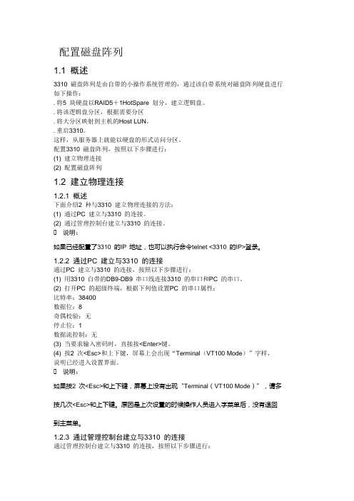
配置磁盘阵列1.1 概述3310 磁盘阵列是由自带的小操作系统管理的,通过该自带系统对磁盘阵列硬盘进行如下操作:.将5 块硬盘以RAID5+1HotSpare 划分,建立逻辑盘。
.将该逻辑盘分区,根据需要分区.将大分区映射到主机的Host LUN。
.重启3310。
这样,从服务器上就能以硬盘的形式访问分区。
配置3310 磁盘阵列,按照以下步骤进行:(1) 建立物理连接(2) 配置磁盘阵列1.2 建立物理连接1.2.1 概述下面介绍2 种与3310 建立物理连接的方法:(1) 通过PC 建立与3310 的连接。
(2) 通过管理控制台建立与3310 的连接。
说明:如果已经配置了3310 的IP 地址,也可以执行命令telnet <3310 的IP>登录。
1.2.2 通过PC 建立与3310 的连接通过PC 建立与3310 的连接,按照以下步骤进行:(1) 用3310 自带的DB9-DB9 串口线连接3310 的串口和PC 的串口。
(2) 打开PC 的超级终端,根据下列值设置PC 的串口属性:比特率:38400数据位:8奇偶校验:无停止位:1数据流控制:无(3) 当要求输入密码时,直接按<Enter>键。
(4) 按2 次<Esc>和上下键,屏幕上会出现“Terminal(VT100 Mode)”字样,说明已经进入设置界面。
说明:如果按2 次<Esc>和上下键,屏幕上没有出现“Terminal(VT100 Mode)”,请多按几次<Esc>和上下键。
原因是上次设置的时候操作人员进入字菜单后,没有退回到主菜单。
1.2.3 通过管理控制台建立与3310 的连接通过管理控制台建立与3310 的连接,按照以下步骤进行:(1) 将控制台工作站的串口A 和StorEdge 3310 磁盘阵列控制器上的串口用DB9-DB9 串口线连接起来,如图1-1所示。
(3) 打开StorEdge3310 的电源,登录到阵列上。
- 1、下载文档前请自行甄别文档内容的完整性,平台不提供额外的编辑、内容补充、找答案等附加服务。
- 2、"仅部分预览"的文档,不可在线预览部分如存在完整性等问题,可反馈申请退款(可完整预览的文档不适用该条件!)。
- 3、如文档侵犯您的权益,请联系客服反馈,我们会尽快为您处理(人工客服工作时间:9:00-18:30)。
手把手教你安装IBM TS3310磁带库(一)一、产品简述TS3310 磁带机性能强大、容量大并且可靠,能够满足磁带存储的巨大要求。
该磁带库模块化程度高且可伸缩性强,从基本磁带库5U控制模块,直到每个配置均是9U的附加扩展单元都在可伸缩范围内。
LTO3的磁带驱动器可以读写原始LTO2数据磁带盒并读取LTO1数据磁带盒。
TS3310磁带库包含磁带库控制模块,固定盒式磁带存储器(30个插槽)、I/O 站(6个插槽)、触摸显示屏、磁带盒处理自动装置以及最多两个LTO 3磁带机。
您可以将多达4个可选扩展模块添加到控制模块。
每个L9U扩展模块可以容纳最多4个LTO3磁带机和最多80个盒式磁带插槽,以及12个可配置I/O站插槽。
该磁带库支持带有LVD Ultra160 SCSI或本机交换光纤通道连接的LTO3磁带机,从而能够与许多开放式系统服务器连接。
1. 前面板组件展示1 存取口2 电源按钮3 绿色供电(液晶指示灯)4 琥珀色操作员干预警报指示灯5 操作员面板(触摸式)6 5U控制模块7 I/O站8 9U扩展模块I/O站I/O站位于磁带库的前面板上,它将在不干扰正常磁带库操作的前提下实现磁带盒的导入和导出,一个控制模块I/O站的容量为6个磁带盒,一个9U扩展模块I/O站的容量为12个磁带盒。
注:此磁带库会读取条形码标签以确定每个插槽中的特定磁带盒,请确保磁带库中的所有磁带盒都有适当的条形码标签。
将I/O站插槽分配给逻辑磁带库时,只有该逻辑磁带库才能访问此插槽。
I/O站将由所有逻辑磁带库共享,但是I/O站插槽一次只能被一个逻辑磁带库占用。
2. 后面板组件展示1 控制模块(L5B)2 扩展模块(E9U)3 控制模块磁带机(显示FC磁带机)4 扩展模块磁带机5 电源控制器6 控制模块与扩展模块的连接线7 客户用网络端口(4端口提供)8 WEB方式管理磁带库接口(RJ45)3. 内部组件存储列(磁带盒位置)机器人系统(即机械臂)IBM网上特惠专营新品热销中!二、在机架中安装新磁带库机器到货后,首先打开包装并检验装运内容是否齐全,待完毕后就是上架的步骤,因为机器结构的设计所以注定了上机过程的谨慎与繁琐,下面详细的讲解下安装过程。
1. 卸下用于保护拾取器组合件的所有内部包装材料注:如果在打开磁带库电源之前未除去所有内部包装材料,则会导致磁带库损坏,所以一定要检查清楚,要不后果很严重啊。
a. 剪断绕在拾取器包装材料上的塑料带(1)。
注:一些磁带库上可能会使用挂钩和环形紧固带代替塑料带。
重要:在除去以下包装材料时,确保不要损坏拾取器组合件,请勿用力过猛。
b. 除去纸板包装材料(2)、泡沫包装材料(3)和小纸板包装材料(图中未显示)。
重要:有一些磁带库信号电缆非常靠近控制模块地板右侧的凸起金属环,在下一步除去塑料带的时候确保不要剪断或损坏这些电缆。
c. 除去塑料带。
塑料带会穿到磁带库底板每侧得凸起金属环下,可能需要在多处剪断塑料带才能将它从金属环除去。
2. 从I/O站的箱上除去黄色带状包装条(图中1显示)按照此步骤都清楚完毕后请再次确认下所拿下的塑料带及固定带。
3. 减轻重量这一步呢,其实是可以省略,具体怎么做还是根据工程师自己当时的情况来决定,如果有帮手,那可以不做这一步,如果只有一、两个人的话那就需要卸掉一点设备来减轻重量,方便机器的抬起上架。
下面简单介绍下可拆卸的部件:卸下电源a. 按逆时针方向旋开电源组件上的两个大头螺丝(2)。
b. 要卸下电源,可以在从下方扶住电源组件的同时,抓紧手柄(1)并将它向外缓缓拉出。
卸下磁带机箱卸下方法同电源的拆卸方法。
4. 准备用于安装的磁带库模块因为每个控制模块都附带顶部和底部盖板,所以为了正确安装磁带库,可能需要将一个或两个盖板从控制模块移动到扩展模块。
完成后,顶部盖板应位于磁带库的顶部模块上,底部盖板应位于磁带库的底部模块上。
当然如果客户就只有一个控制模块,就不需要拆卸顶部或底部盖板了。
如果要将底部盖板从控制模块转移到扩展模块,首先要嵌合拾取器组合件锁定机制(下图的1显示),需要抬起拾取器组合件才能够完成嵌合锁定机制。
此装置是为了在您拆除底部盖板后挡住下滑的拾取器,不让拾取器划出控制模块的轨道而造成损失(下图2显示)。
接下来使整个5U控制模块侧翻,卸下底板周围5个底部螺丝(下图1显示)重要:请勿旋松或卸下固定主传感器的螺丝(下图2显示),该螺丝与底部盖板螺丝具有相同的螺丝头,但它长度较长,具有粗牙螺纹,用于旋入塑料主传感器中。
除去螺丝后卸下底板,安装在扩展模块(E9U)的底部,并确保主传感器塑料块状在底部盖板内侧(下图1显示),用刚才卸下的5颗螺丝旋紧扩展模块底部盖板。
如果是要从顶部盖板从控制模块转移到扩展模块,那么操作步骤基本同底部盖板的拆卸方法,顶部盖板有四颗螺丝(下图1显示)。
5. 在机架中安装底部磁带库模块准备好模块来进行安装后,先开始安装将位于磁带库底部的模块。
注:磁带库中的底部模块是唯一应已安装了底板的模块,顶部模块是唯一应已安装了顶部盖板的模块。
首先对于所有的配置,请确保前部和后部齿条都在高位锁定。
(下图2显示)确认完齿条的位置后,可利用提供的吊索将底部模块抬起,然后滑到机架中的导轨板上,直到它接触到每个机架安装导轨后部的凸缘后,安装并旋紧每个机架安装导轨后部凸缘上的后部大头螺丝。
(下图1显示)6. 安装磁带库配置中的其他模块,这里以安装控制模块为例。
抬起刚才被卸掉了底板的控制模块(需再次确保拾取器组合件锁定机制已处于锁定状态),按同样的方法利用吊索将控制模块滑动到已安装模块的顶部上,待全部滑入后检查边缘是否对齐,打卡上方模块的I/O站门和检修门,露出检修门后的定位销(下图1显示),旋紧此定位销,旋紧前部大头螺丝(下图2显示)和I/O站门后面的大头螺丝,将上方模块的前端固定到下方模块。
固定完上下模块后,最首要的任务就是将齿条向下位移动到低位,使上下两个模块内的齿条衔接正常,不能出现明显的空缺距离或错位,请务必检查这点,笔者曾经就因为没有把齿条放到低位,接缝处有小段空缺,致使机械臂在运行时不能完成自检步骤导致机器无法使用,最后还是惊动了IBM工程师上门,哈哈。
这种齿条前后各有一条,控制齿条上下移位的那个装置非常的隐蔽,前一个在模块正面的检修门内,需要打开检修门才能操作,而后一个则需要把磁带驱动器抽出来才能看得到。
齿条下移后检查下接口处,平稳过渡就算大功告成。
如果是再安装一个扩展模块的话,步骤也是一样的,关键的问题还是要仔细确保上下齿条连接正常,这点很重要。
接着安装机架协助板,以确保模块固定在机架板上。
最后,启用拾取器组合件,也就是把拾取器组合件往磁带槽位方向旋转(下图中箭头方向),使得机械臂能够自如的上下移动便可(下图1显示),建议把机器臂从下到上再从上到下滑动几遍,观察其滑动状态,确认没有抖动或异想后就可以放心使用。
至此,TS3310磁带库的上架安装已经完毕,连接好电源就可以做开机自检的准备了。
手把手教你安装IBM TS3310磁带库(三)三、用户界面该磁带库有一个本地界面“操作员面板”,以及一个远程WEB用户界面。
操作员面板位于控制模块前门上,用户界面显示在操作员面板触摸屏LCD显示器上,用于执行基本库管理功能。
当用户触摸触摸屏上的按钮时会发出声音提示。
登录屏幕要填写User name,轻敲空白字段以显示字母和数字触摸板,然后使用触摸键拼出用户标识,然后触摸OK,同样的方法输入Password并触摸OK。
对于首次登录,管理员应适用以下帐户:User name:adminPassword:secure公共操作员面板元素公共标题元素所有操作员面板屏幕在标题中包含了以下公共元素:1 Home –显示缺省的Capacity View屏幕2 Help –相关页面的上下文相关帮助3 Logout –注销键4 Logical Library # -- 显示当前逻辑库的名称,可以单击库名称的任一侧上的箭头以便滚动查看其它可用逻辑库。
系统摘要和子系统状态磁带库的运行状态可由位于主页底部的三个子系统状态按钮判断。
如发生问题,通过这些按钮可以轻松了解库的运行状态,以便进行快速恢复。
可以选择这些按钮来查看有关库的详细消息,并且可访问库子系统。
这三个子系统为:5 Library –打开库菜单选择屏幕,然后打开库的操作员干预屏幕。
此屏幕一般会显示系统目前正存在的错误日志,点击错误日志可以看到系统为之提供的解决方法。
6 Drives –打开磁带机的操作员干预屏幕。
7 Media –打开介质的操作员干预屏幕。
操作员面板提供的菜单1 Setup菜单由可用来设置和配置库各个方面的命令组成,包括逻辑库连接、网络、物理库、用户、日期和时间、许可证和SNMP陷阱定位。
2 Operations菜单由可用来更改库操作方式、导入和导出盒带、装入和卸装磁带机、移动介质以及关闭/重新启动库的命令组成。
3 Tools菜单由可用来维护库的命令组成,例如查看操作员干预、捕获库快照、识别端口以及使用FMR(固体)盒带更新固件。
说到这里,TS3310磁带库的上架安装及基本操作都已交代清楚,笔者在安装过程中遇到的问题及解决方法也一一表达,希望能给一些不常安装或是第一次安装此类磁带库的工程师提供些帮助。