FW345使用手册
Fluke 345电压质量电流计说明书
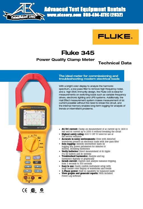
Technical Data• AC/DC current: Clamp-on measurement of ac current up to 1400 A rms and dc current up to 2000 A without breaking the circuit • Highest safety rating: 600 V CAT IV rated for use at the service entrance• Accurate in noisy environments: Even with distorted waveforms present on electronic loads with low-pass filter • Data logging: Identify intermittent faults by logging any power parameters for minutes or months, including harmonics• Verify batteries: Direct measurement of dc ripple (%) for battery and dc systems• Troubleshoot harmonics: Analyze and log harmonics digitally or graphically• Inrush current: Capture and analyze nuisance tripping, from 3 seconds to 300 seconds• Easy to use: Easily confirm instrument setup with large backlit color display of waveforms and trends • 3-Phase power: Built in capability for balanced loads •View graphs and generate reports: With included Power Log softwareFluke 345Power Quality Clamp MeterWith a bright color display to analyze the harmonicspectrum, a low-pass filter to remove high frequency noise, and a high EMC immunity design, the Fluke 345 is ideal for measurements on switching loads such as variable frequency drives, electronic lighting and UPS systems. Additionally, the Hall Effect measurement system makes measurement of dc current possible without the need to break the circuit, and the internal memory enables long-term logging for analysis of trends or intermittent problems.N1014019812 Fluke Corporation Fluke 345 Power Quality Clamp MeterLog measured parametersAll voltage, current, power, and harmonic measurements can be logged for minutes, hours, or months. Measurementaveraging periods from 1 second to 15 minutes can be selected depending on the application.Measured parameters can be logged into three separate recording memory areas. If longer recordings are required, the three areas may be combined into one. Stored measurements can be recalled and displayed on-screen in normal screen format or downloaded using the Power Log software package.ApplicationsSet up and troubleshoot variable frequency drives and UPS systems - Verify correct operation by measuring key parametersHarmonics measurements - Uncover harmonic issues that can damage or disrupt critical equipmentInrush capture - Check start-up current where spurious resets or nuisance circuit breaker tripping occurs Load studies - Verify electrical system capacity before adding loadsHarmonics measurements—view keyharmonic factors such as distortion factor and total harmonic distortion, as well as individual harmonics up to the 30thharmonic.Log parameters over time to track down intermittent faults.3 Fluke Corporation Fluke 345 Power Quality Clamp MeterFlexible and easy to useThe 345 measures a wide range of electrical parameters and can be used for many applications in today’s modern electrical environment. Measuring mode is selected by a simple turn of the rotary switch and the large color display presents data in a clear, easy-to-understand way.By default the display will show the most commonmeasurements, in very large format. If more detailed views are required they are available with the press of a single key (up to six measurements at once).Equipment performancemeasurement - power consumed by single- and three-phase balanced loads.View waveforms for equipment checking and setup.View recorded datain simple graphs and tables.Easily customizethe report.Create professional reports.Analysis and reporting softwareDesigned to quickly view recorded data, theincluded Power Log software displays all recorded parameters on interactive trends. Generate professional reports with the ‘Report Writer’ function, or copy and paste images into report document manually.• Easy-to-use tabbed window format allowsquick data evaluation.• One-step download and display capability • Waveform, harmonics, and trend download • Simple data export to other applicationsInrush currentDiagnose equipment start-ups with the inrush current mode. A current trigger level is set prior to recording. Once the level has been exceeded, the meter will begin capture. Recordings from 3 seconds to 300 seconds may be captured, and up to 1000 inrush events may be stored in the instruments memory.Screen captures and data loggingAny measurement can be stored in memory for later viewing, or downloaded to a PC. Simply press ‘SAVE’ to capture the active screen to memory – up to 50 screen shots can besaved for quick and simple documentation. Additionally, over 150,000 individual measurements can be logged for later review on the display or on a PC using Power Log software.Ambient conditions (For indoor use only)Reference conditions All accuracies stated at 23 °C ± 1 °C (73.4 °F ± 1.8 °F)Operating temperature0 °C to 50 °C (32 °F to 122 °F)Temperature coefficient of current≤ ± 0.15 % of rdg per °CTemperature coefficient of voltage≤ ± 0.15 % of rdg per °CMaximum relative humidity80 % for temperatures up to 31 °C (87 °F) decreasing linearly to 50 % relative humidity at40 °C (104 °F)Maximum operating altitude2000 mElectrical safetySafety IEC 61010-1 600 V CAT IV, double or reinforced insulation, pollution degree 2Protection IP40; EN60529Maximum safe working voltagesCurrent measurement 600 V ac rms or dc between uninsulated conductor and groundVoltage measurement600 V ac rms or dc between either input terminal and ground, or 825 V between energizedphase voltages (delta power config.)EMCEmission IEC/EN 61326-1:1997 class BImmunity IEC/EN 61326-1:1997MechanicalDimensions (length x width x depth)300 mm x 98 mm x 52 mm (12 in x 3.75 in x 2 in)Weight including batteries820 g/1.8 lbJaw opening60 mmJaw capacity58 mm diameterCleaning The unit can be cleaned with an Isopropanol impregnated cloth. Do not use abrasives orother solvents.4 Fluke Corporation Fluke 345 Power Quality Clamp Meter5 Fluke Corporation Fluke 345 Power Quality Clamp MeterVoltage measurement (dc, dc rms, ac rms)Measuring range0 to 825 V dc or ac rms Autorange facility 4 V/40 V/400 V/750 V Resolution 1 mV in 4 V range10 mV in 40 V range100 mV in 400 V range1 V in 750 V range AccuracyDC and dc rmsV > 1 V± 1 % rdg ± 5 digitsV < 1 V± 0.02 VAVGV > 1 V± 3 % rdg ± 5 digitsV < 1 V0.03 VPkV > 1 V± 5 % rdg ± 5 digitsV < 1 V± 0.03 VCF (Crest Factor)1.1 ≤ CF < 3± 3 % rdg ± 5 digits3 ≤ CF < 5± 5 % rdg ± 5 digitsResolution0.01RPL (Ripple)2 % ≤ RPL < 100 %±3 % rdg ± 5 digits100 % ≤ RPL < 600 %± 5 % rdg ± 5 digitsResolution0.1 %V dc> 0.5 V, V ac> 0.2 VAll measurements dc and 15 Hz to 1 kHzMaximum overload 1,000 V rmsVolts rms is a true-rms measurement (ac + dc)HarmonicsTHD (Total Harmonic Distortion)1 % ≤ THD < 100 %± 3 % rdg ± 5 digits100 % ≤ THD < 600 %± 5 % rdg ± 5 digitsResolution0.1 %DF (Distortion Factor)1 % ≤ DF < 100 %± 3 % rdg ± 5 digitsResolution0.1 %H02 ≤ V harm< H13± 5 % rdg ± 2 digitsH13 ≤ V harm ≤ H30± 10 % rdg ± 2 digits All measurements up to 30th harmonic (40th harmonic for 15 Hz to 22 Hz) Frequency range F0 15 Hz to 22 Hz and 45 Hz to 65 HzV acrms> 1V6 Fluke Corporation Fluke 345 Power Quality Clamp MeterPower factor (single- and three-phase)Power factorMeasuring range0.3 capacitive and 1.0 to 0.3 inductive (72.5° capacitive and 0° to 72.5° inductive) Resolution0.001Accuracy± 3°Frequency range15 Hz to 1 kHzDisplacement power factorMeasuring range0.3 capacitive and 1.0 to 0.3 inductive (72.5° capacitive and 0° to 72.5° inductive) Resolution0.001Accuracy± 3°Frequency range15 Hz to 22 Hz and 45 Hz to 65 Hz7 Fluke Corporation Fluke 345 Power Quality Clamp MeterMeasuring range40,000 kWHrAutorange facility 1 kWHr, 40 kWHr, 400 kWHr, 4,000 kWHr, 40,000 kWHr Resolution 1 WHr in 4 kWHr10 WHr in 40 kWHr100 WHr in 400 kWHr1 kWHr in 4,000 kWHr10 kWHr in 40,000 kWHrAccuracykWHr > 2 kWHr± 3 % ± 5 digitskWHr < 2 kWHr± 0.08 kWHrAll Watts /VA /VAR /PF measurementsFrequency range DC and 15 Hz to 1 kHzCurrent range10 A to 1400 A rmsVoltage range 1 V to 825 V rmsMaximum input825 V rms/1400 A rmsMaximum overload1000 V rms/10,000 AFrequency measurement(from current or voltage sources)Measuring range15 Hz to 1 kHzResolution0.1 HzAccuracy15 to 22 Hz ± 0.5 % rdg40 Hz to 70 Hz ± 0.5 % rdg15 Hz to 1000 Hz ± 1% rdgCurrent range10 A to 1400 A rmsVoltage range 1 V to 825 V rmsScope functionCurrent measurementRanges10 A/20 A/40 A/100 A/200 A/400 A/1000 A/2000 AResolution 1 A in 40 A10 A in 400 A50 A in 2000 AAccuracy± 3 % rdg ± 1 pixelMaximum overload 10,000 AVoltage measurementRanges 4 V/10 V/20 V/40 V/100 V/200 V/400 V/1000 VResolution100 mV in 4 V1 V in 40 V10 V in 400 V31.25 V in 1000 VAccuracy± 2 % rdg ± 1 pixelMaximum overload 1000 V rmsFrequency range DC and 15 Hz to 600 HzTime base 2.5 ms, 5 ms, 10 ms, 25 ms, 50 ms/divRefresh rate0.5 secondsMaximum sampling rate15.625 kHz8 Fluke Corporation Fluke 345 Power Quality Clamp MeterRanges40 A, 400 A, and 2000 AResolution10 mA in 40 A range100 mA in 400 A range1 A in 2000 A rangeAccuracyI > 10 A± 5 % rdg ± 1 pixelI < 10 A± 0.5 AAll measurements dc and 15 Hz to 1 kHzMaximum overload Maximum overload 10,000 A or rms x frequency < 400,000Amps rms is a true-rms measurement (ac + dc)Capture time 1 s, 3 s, 10 s, 30 s, 100 s, and 300 sMaximum sampling rate15.625 kHzInterfaceUSB Interface to a PCPower Log software for download, analysis, and reporting345 Upgrade Utility for installing a new firmware versionLogging MemoryLogging areas Three areas that can be used individually or combined into one large area Averaging periods 1 s, 2 s, 5 s, 10 s, 30 s, 1 min, 5 min, 10 min, 15 min, and custom9 Fluke Corporation Fluke 345 Power Quality Clamp MeterLogging timesVolts and current modeAverage time Logging time (1 area)Logging time (3 areas)1 s 1 h 49 m 5 h 12 m2 s3 h 38 m10 h 24 m5 s9 h 06 m 1 d 2 h 00 m10 s18 h 12 m 2 d 04 h 00 m30 s 2 d 06 h 36 m 6 d 12 h 01 m1 min 4 d 13 h 12 m13 d 00 h 03 m5 min22 d 18 h 00 m65 d 00 h 15 m10 min45 d 12 h 00 m130 d 00 h 30 m15 min68 d 06 h 00 m195 d 00 h 45 mV & A harmonics modeAverage time Logging time (1 area)Logging time (3 areas)1 s0 h 34 m 1 h 38 m2 s 1 h 08 m3 h 16 m5 s 2 h 52 m08 h 11 m10 s 5 h 44 m16 h 23 m30 s17 h 13 m 2 d 01 h 11 m1 min 1 d 10 h 26 m 4 d 02 h 23 m5 min7 d 04 h 10 m20 d 11 h 25 m10 min14 d 08 h 20 m81 d 0 h 50 m15 min21 d 12 h 30 m121 d 13 h 15 msingle- and three-phase power modeAverage Time Logging Time (1 area)Logging Time (3 areas)1 s 1 h 40 m 4 h 47 m2 s3 h 21 m9 h 34 m5 s8 h 22 m23 h 57 m10 s16 h 45 m 1 d 23 h 54 m30 s 2 d 02 h 17 m 5 d 23 h 42 m1 min 4 d 04 h 35 m11 d 23 h 25 m5 min20 d 22 h 55 m59 d 21 h 05 m10 min41 d 21 h 50 m119 d 18 h 10 m15 min62 d 20 h 45 m179 d 15 h 15 m10 Fluke Corporation Fluke 345 Power Quality Clamp Meter11 Fluke Corporation Fluke 345 Power Quality Clamp Meter Fluke Corporation PO Box 9090, Everett, WA USA 98206Fluke Europe B.V. PO Box 1186, 5602 BD Eindhoven, The NetherlandsFor more information call: In the U.S.A. (800) 443-5853 or Fax (425) 446-5116 In Europe/M-East/Africa +31 (0) 40 2675 200 or Fax +31 (0) 40 2675 222 In Canada (800) 36-FLUKE or Fax (905) 890-6866 From other countries +1 (425) 446-5500 or Fax +1 (425) 446-5116 Web access: ©2007 Fluke Corporation. All rights reserved. Specifications subject to change without notice. Printed in U.S.A. 1/2007 2643038 D-EN-N Rev C Fluke. Keeping your world up and running.™Ordering informationFluke-345Power Quality Clamp Meter Includes Soft carrying case Power Log software Test leads Alligator clips Test probes USB cable International ac adapter / battery eliminator Printed English language user manual Multi-language manual CDRecommended Accessories:TP220 SureGrip ™ Industrial Test Probes - One pair (red, black) of Industrial test probes. Sharp, 12 mm stainless steel tip provides reliable contact. Use with TL224 test leads.AC220 SureGrip ™ Alligator Clips - One pair (red, black) of small, insulated, nickel plated jaws. Blunt tip grabs round screwheads up to 9.5 mm. Use with TL224 test leads.TP1 Slim Reach Test Probes - One pair (red, black) of slender probe bodies for probing closely spaced or recessed terminals. Hard stainless steel probe tips with flat blade design to hold securely in blade type electrical wall sockets.L200 Probe Light - Small, rugged, and light the L200 easily attaches to any Fluke test probe. Bright white LED illuminates contact area and frees hands for work.L210 Probe Light and Probe Extenders - Includes L200 Probe Light and TP280 Test Probe Extenders to keep hands away from live circuits and light work area C550 Tool Bag - Steel reinforced frame with heavy duty hardware and large zippered storage compartment includes 25 pockets. Allows you to carry all your tools to the job site.TLK291 - Fused Test Leads provide extra safety with retractable sheath protectingcontact points.。
高压数字兆欧表3455说明书

7
安全信息
测量类别 ( 过压类别 )
该仪器满足 CAT IV (600 V)、CAT III
(1000 V) 的安全要求。
为了确保测量仪器的安全操作,IEC61010 建立有各种电气环境下的安全标准,分为
1
CAT I 到 CAT IV 类,也称测量分类。定义
如下:
CAT I 备用电气电路通过变压器或类似装置与交流电插座相连。
8
6.3 输入用外部温度计
和湿度仪测得的温度和湿度 ......... 129
6.3.1 输入和保存 ...................... 130
9
6.3.2 清除保存数据中的
温度和湿度显示 .................. 133
6.4 与 PC 通信 ........................ 134
8 保养和维修
159
8.1 故障排查..........................160 8.2 清洁..............................162 8.3 报错显示..........................162 8.4 进行系统复位 .....................165 8.5 仪器报废..........................166
345M操作说明书
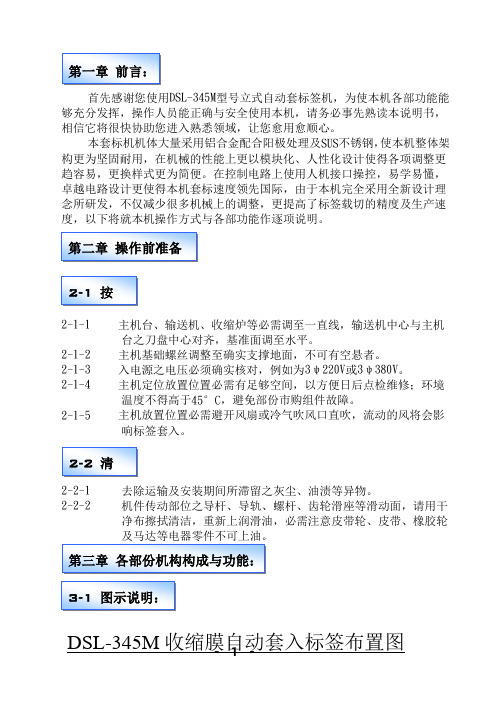
DSL-345M型号立式自动套标签机,为使本机各部功能能相信它将很快协助您进入熟悉领域,让您愈用愈顺心。
本套标机机体大量采用铝合金配合阳极处理及SUS不锈钢,使本机整体架构更为坚固耐用,在机械的性能上更以模块化、人性化设计使得各项调整更趋容易,更换样式更为简便。
在控制电路上使用人机接口操控,易学易懂,卓越电路设计更使得本机套标速度领先国际,由于本机完全采用全新设计理2-1-2主机基础螺丝调整至确实支撑地面,不可有空悬者。
2-1-3入电源之电压必须确实核对,例如为3ψ220V或3ψ380V。
2-1-4主机定位放置位置必需有足够空间,以方便日后点检维修;环境温度不得高于45°C,避免部份市购组件故障。
切之动作。
3-2-2机台架:全机采砂面SUS不锈钢材质,用于支撑主机及固定输送带。
3-2-3收缩炉(电热或蒸气式):使用电热或蒸气之热将套入瓶子之标签收缩均匀附贴于瓶上。
3-2-4驱动组:采双组机构式同步伺服马达控制,使收缩膜做定尺寸输送。
3-2-5分瓶螺杆组:将入料欲套标之瓶子,利用螺杆定距输送,使瓶子能等距分开,以利标签套入。
3-2-6带瓶组:采两侧同步传动,高低与夹瓶定位仅各一只手轮调整,目的使瓶子于输送时不摇晃与套标签高度之设定。
3-2-7钉住、预收缩炉:使标签能预先收缩一部份固定于瓶子,避免标签下滑移动或偏摆。
3-2-8中心柱:将标签膜料套入撑开,使膜料得以传送与裁切。
3-2-9电眼架组:使用光纤电眼传送信号,提供控制系统做定尺寸输送,电眼位置高低调整,确定刀盘内之刀片裁切位置。
3-2-10毛刷组:利用束带或橡皮筋将套入瓶子标签刷打入定位。
3-2-11刷下组:采用同步调整机构,将刷下两组传送轮调整至中心柱下方滚轮轻微接触,待标签通过时以较高转速将标签投射入瓶子。
3-2-12料架组:标签膜料之固定纸环可由5”至10”调整后设定,出料由一组输送滚轮减速马达压送供料。
3-2-13输送带:使用变频器调整输送带速度,以适用于各产能之速度匹配,本机更以同步控制将分瓶螺杆组、带瓶组、本输送带三者做成单一旋钮调速,使得生产速度之调整更加方便与容易。
FW345(B)测速与超速保护卡
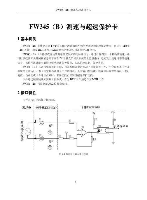
FW345(B)测速与超速保护卡1基本说明FW345(B)卡件是在原FW345基础上改进的脉冲频率型测速和超速保护模块,通过与TB345(B)连接,构成DEH系统与MEH系统的测速与超速保护I/O单元。
FW345(B)卡件能接收现场的测速装置发来的电脉冲信号,通过计算得到一个精确的转速,还可以接收油开关跳闸和紧急停车两个DI干触点信号及相应的上位机指令,进而发出快速可靠的超速信号,该信号通过继电器输出驱动超速保护装置,实现超速限制、保护功能。
FW345(B)具备带电插拔的功能。
可在系统带电的情况下直接插拔卡件,不会影响本卡件及系统的正常运行。
本卡件定期检测自身工作的情况。
具有看门狗功能,能在卡件异常的情况下进行复位。
当系统或卡件通信故障时,卡件仍能正常实现超速保护功能。
卡件通过硬件跳线来判断工作方式:作为DEH工作还是作为MEH工作。
FW345(B)与控制器FW247配套使用。
2接口特性卡件的接口电路如下图所示:图 2-1转速信号输入接口电路图 2-2油(真空)开关或紧急停车信号输入接口电路图 2-3 3选2 报警输出接口电路3卡件使用说明FW345(B)卡件结构简图如图 3-1所示。
图 3-1 卡件外观3.1指示灯说明面板指示灯说明如表 3-1(按照面板从上到下的顺序)。
表 3-1 面板指示灯说明名称含义状态FAIL 卡件故障指示灯正常情况下灭。
当卡件故障或者复位时,FAIL灯亮。
RUN 卡件程序运行指示灯正常情况下RUN闪烁。
WORK 卡件工作指示灯正常情况下常亮。
COM 卡件通讯指示灯正常情况下闪烁POWER 卡件内部24V指示灯正常情况下常亮SLIP 油开关跳闸指示灯跳闸点亮,反之灭TRIP 紧急停车指示灯系统紧急停车点亮,反之灭103A 103%报警输出第一路报警时点亮,反之灭103B 103%报警输出第二路报警时点亮,反之灭110A 110%报警输出第一路报警时点亮,反之灭110B 110%报警输出第二路报警时点亮,反之灭3.2端子板选择FW345(B)通过TB345(B)与现场侧相连,1块TB345(B)对应3块FW345(B)。
深圳市锐尔威视科技有限公司 REVB-A50 产品使用手册说明书

A50方案板产品使用手册深圳市锐尔威视科技有限公司2019.9.5 Ver.A目录目录硬件资源描述 (4)核心硬件资源 (4)接口资源 (4)显示驱动能力 (5)视频编解码能力 (5)底板接口资源 (5)软件资源描述 (6)提供JA VA层API源码 (6)底板硬件设计说明 (6)接口说明 (7)接口定义描述 (8)扩展模块连接说明 (11)MIPI屏 (11)LVDS屏 (12)RGB屏 (12)MIPI摄像头 (13)4G通讯模块 (13)更新固件方法 (14)USB更新 (14)TF卡更新 (16)固件修改工具使用说明 (18)安装D RAGON F ACE (18)修改开机信息 (19)第一张开机L OGO (19)第二张开机L OGO (20)开机动画和开机音乐 (20)修改系统配置 (20)修改系统属性BUILD.PROP (21)修改INIT.RC (21)修改LCD配置 (22)修改触摸配置 (22)修改屏幕旋转方向 (22)修改自启动应用 (22)串口使用说明 (23)GPIO说明 (24)硬件资源描述核心硬件资源CPU:全志A50四核主频1.5GHzGPU:Mali-400MP2PMU:AXP2231DRAM:1GB LPDDR3FLASH:8GB eMMCWIFI+BT:XR829集成Audio Codec接口资源1路USB OTG 2.0,可做HOST1路USB HOST 2.0 高速ECHI协议480Mbps1路SDIO,可接SD卡1组RGB/LVDS复用的显示屏接口1组MIPI-DSI显示屏接口1组MIPI-CSI摄像头接口1路音频Headphone2路音频Microphone1路LRADC,可做按键检测1路SPI接口1路I2S接口,用于接声卡芯片2路IIC接口,用于接CTP、G-Sensor等3路UART接口5个GPIO口复位信号输入开关机按键,支持休眠唤醒提供5组外设电源,给LCD、CTP、Camera等外设供电支持外部DC、锂电池、USB三种供电方式,自动检测支持由DC-5V和USB给电池充电PCBA尺寸:59mm*46mm引脚数量:132显示驱动能力RGB:18bit 1920*1080 5/7寸转接双8LVDSLVDS:单8 1366*760 7~15寸MIPI:4-lane 1920*1200 5~10寸视频编解码能力编码能力:1080P@60fps H.264/MJPEG解码能力:1080P@60fps H.264/MJPEG多种格式解码:Mpeg1/2, Mpeg4 SP/ASP GMC, H.263, H.264 BP/MP/HP, VP8, WMV9/VC-1等底板接口资源4个USB2.0口,2个A母座,其中一个可用于Device,2个4P-2.0插座3组TTL串口(其中1组可复用为一个SPI)1个TF卡座,支持最大64G容量TF卡1个耳机插座1个麦克风接口1个MIPI-CSI摄像头接口1个百兆以太网RJ45接口1个RGB屏接口,带电容触摸接口1个LVDS屏接口,带电容触摸接口1个MIPI屏接口,带电容触摸接口1组SPI接口(可复用为串口)1组IIC接口1组按键接口:POWER RESET LRADC5个GPIO全网通4G模块MiniPCI-E插座标准SIM卡座RTC电池座CR1220锂电池接口,支持3.7~4.2V电池DC5.5电源座,12V电源输入4P-2.54插座,12V电源输入4P-2.54插座,5V和3.3V电源输出(WIFI+BT集成在核心板上)PCBA尺寸:135mm*85mm软件资源描述搭载Android8.1系统(内核版本:Linux-4.9),系统经过锐尔威视科技深度优化定制,启动快,运行流畅不死机,已ROOT,可做带Google GMS认证的系统;支持WIFI、蓝牙、以太网、4G网络;支持RGB、LVDS、MIPI接口的屏幕;用户可由PC端的固件修改工具定制个性化固件,如修改开机图片、开机动画、开机声音、安装/卸载应用、自启动应用、更改LCD屏配置、设置屏幕旋转方向、修改机器信息等,不开放系统源码,仅提供固件,用户可直接开发APP,节省开发周期,可为项目用户定制系统。
345 电能质量钳表 用户手册 (简体中文)说明书

®345Power Quality Clamp Meter用户手册(Simplified Chinese)October 2006© 2006 Fluke Corporation. All rights reserved.Product names are trademarks of their respective companies.有限担保和有限责任Fluke担保在正常使用和保养的情况下,其产品没有材料和工艺上的缺陷。
担保期为从购买产之日起的一年内。
部件、产品修理和服务的担保期限为90天。
本担保仅限于Fluke授权零商的原购买人或最终用户,并且不适用于一次性电池、电缆接头、电缆绝缘接头或Fluke认为于误用、改装、疏忽、污染及意外或异常操作或处理引起的任何产品损坏。
Fluke担保软件依照功能规格正常运行90天,并且软件是记录在无缺陷的媒介上。
Fluke并不担保软件无错或在运行中不会中断。
Fluke授权的零售商应仅对最终用户就新的和未使用的产品提供本担保,但无权代表Fluke公司提供额外或不同的担保。
只有通过Fluke 授权的销售店购买的产品或买方已经按适的国际格付款才能享受Fluke的担保支持。
在一国购买的产品需在他国修理时,Fluke有权向买方求负担重大修理/零件更换费用。
Fluke的担保为有限责任,由Fluke决定是否退还购买金额、免费修理或更换在担保期间退还Fluke授权服务中心的故障产品。
如需要保修服务,请与您就近的Fluke授权服务中心联系,获得退还授权信息;然后将产品寄至务中心并附上产品问题描述,同时预付运费和保险费(目的地离岸价格)。
Fluke不承担运途中发生的损坏。
在保修之后,产品将被寄回给买方并提前支付运输费(目的地交货)。
如果Fluke认定产品故障是由于疏忽、误用、污染、修改、意外或不当操作或处理状况而产生包括未在产品规定的额定值下使用引起的过压故障;或是由于机件日常使用损耗,则Fluke会估算修理费用,在获得买方同意后再进行修理。
施耐德电气 IS 345 红外运动传感器 - COM1 - 表面,四方形说明书
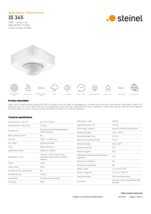
EAN 4007841 010485Article number 010485infrared sensor360°max. 20 x 4 m2000 W max. (LED-ready)IP54 2 - 1000 lux 5 sec - 15 min manual override 4h ideal 2,5 - 5 m Teach mode energy savingFunction descriptionHuge reach. Infrared motion detector IS 345 for indoors and out, ideal for passageways, corridors and commonly used spaces, installation height 5 m, detection zone 12 x 6 m (radial) and 23 x 6 m (tangential), large terminal compartment for easy installation, heavy-duty relay for high switching capacity. Available either in round or square surface-mounted, concealed or In-ceiling installation.Technical specificationsDimensions (L x W x H)65 x 95 x 95 mm Manufacturer's Warranty 5 yearsSettings via Remote control, Potentiometers, Smart Remote With remote control NoVersion COM1 - surface, sq.PU1, EAN 4007841010485TypeMotion detectors Application, place Outdoors, IndoorsApplication, room corridor / aisle, multi-storey / underground car park, outdoors, Indoors Colour white Colour, RAL9003Includes corner wall mount No Installation site ceilingInstallation Surface wiring, Ceiling IP-ratingIP54LED lamps > 8 W 600 W Capacitive load in μF 176 µFTechnology, sensors passive infrared, Light sensor Mounting height 2,50 – 5,00 m Mounting height max.5,00 m Optimum mounting height 2,8 m Detection angle Aisle, 360 °Angle of aperture 45 °Sneak-by guardYes Capability of masking out individual segmentsYes Electronic scalability No Mechanical scalability NoReach, radial 12 x 6 m (72 m²)Reach, tangential 23 x 6 m (138 m²)Switching zones 280 switching zonesFunctionsNormal / test mode, Manual ON / ON-OFFhttps://www.steinel.deEAN 4007841 010485Article number 010485 Technical specificationsAmbient temperature-20 – 50 °CMaterial PlasticMains power supply220 – 240 V / 50 – 60 Hz Switching output 1, resistive2000 WSwitching output 1, number ofLEDs / fluorescent lamps8 pcs.Fluorescent lamps, electronic ballast1500 WFluorescent lamps, uncorrected1000 VAFluorescent lamps, series-corrected400 VAFluorescent lamps, parallel-corrected400 VASwitching output 1, low-voltagehalogen lamps2000 VALED lamps < 2 W100 WLED lamps > 2 W < 8 W300 W Twilight setting 2 – 1000 lx Time setting 5 s – 15 Min. Basic light level function NoMain light adjustable NoTwilight setting TEACH YesConstant-lighting control No Interconnection YesType of interconnection Master/master Interconnection via Cable Interconnection, number max. 10 sensorsAccessoriesEAN 4007841 009151Remote control Smart RemoteEAN 4007841 559410Service remote control RC8EAN 4007841 056711Black cover for IR-sensorshttps://www.steinel.deEAN 4007841 010485Article number 010485Detection Zone Dimension DrawingMaster circuit diagramhttps://www.steinel.deEAN 4007841 010485Article number 010485Circuit diagram for interconnecting several sensorsConnection using two-circuit switch for manual and automatic operation Circuit diagram Connection via a changeover switch for continuous and automatic operationhttps://www.steinel.de。
FW346使用手册
电液伺服卡FW3461基本说明电液伺服卡FW346作为汽轮机DEH(数字式电气液压控制)系统的专用模块卡,与电液伺服阀门、阀门位移反馈装置等组成电液伺服回路,控制电液伺服阀门的开度。
FW346通过与端子板TB346配套使用,构成完整的DEH电液伺服控制单元,用来接受汽轮机油动机行程的电信号、油开关跳闸信号、手动增/减等信号。
卡件可以输出电流或电压信号驱动DDV (直动式伺服阀)阀的开度,通过油路控制,转换成压力信号,以驱动汽机上的调节阀。
电液伺服卡FW346的主要功能:(1)DEH汽轮机控制系统的手动和自动控制装置,用于控制汽轮机电液伺服阀的开度。
(2)监测电液伺服阀的位置等信号。
(3)实现手动和自动的切换。
(4)与主控制卡进行通信。
电液伺服卡FW346的基本性能:(1)本单元的控制周期定时为20ms,即控制输出和开关的输入输出的刷新周期为20ms。
(2)卡件内部引入PI控制算法来进行闭环控制,从而能够稳定地控制汽机调节阀的开度。
(3)产生10Hz和20Hz两种频率且幅值可调的防止伺服阀和油动机卡涩的振荡信号。
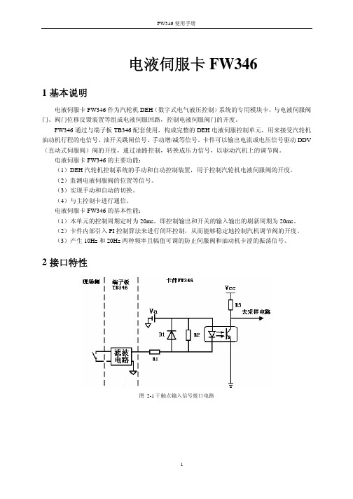
2接口特性图 2-1干触点输入信号接口电路图 2-2干触点输出信号接口电路图 2-3电压信号输出接口电路图 2-4电流信号输出接口电路图 2-5标准电压信号输入电路图 2-6标准电流信号输入电路图 2-7 LVDT(线性位移传感器)信号输入电路3使用说明3.1信号类型表 3-1卡件连接信号类型说明通道数通道类型信号类型功能去向电流输出AO:(0~10)mA;(-20~20)mA;(4~20)mA;(0~20)mA现场第一部分:DDV阀门控制输出1路电压输出AO:(0~5)V;(1~5)V;(0~10)V;(-10~10)V驱动DDV阀现场第二部分:LVDT反馈信号显示1路电流输出AO:(0~20)mA 对应阀位(0~100)%高选后的LVDT信号反馈值手操器1路 DO通道1 DO:继电器输出手/自动反馈手操器1路 DO通道2 DO:继电器输出保留保留1路紧急停机 DI:干触点输入干触点输入手操器1路油开关跳闸信号 DI:干触点输入干触点输入现场1路手操器手/自动信号 DI:干触点输入干触点输入手操器1路手操器手动增加信号DI:干触点输入干触点输入手操器第三部分:开关量信号1路手操器手动减小信号DI:干触点输入干触点输入手操器LVDT信号输入油动机行程反馈LVDT1通道LVDT2通道LVDT标准信号现场第四部分:模拟量输入2路经变送器转换的油动机行程反馈油动机行程信号1油动机行程信号2(-5~5)V;(0~5)V;(-20~20)mA;(0~20)mA现场3.2基本功能3.2.1伺服控制功能(1)本卡件具有快速的模拟比例积分控制功能。
测速与超速保护卡FW345使用手册
测速与超速保护卡FW3451基本说明FW345智能型汽轮机测速与超速保护卡,是汽轮机控制系统的专用模块。
通过与TB345端子板连接,构成DEH系统的测速与超速保护I/O单元。
FW345接收现场的汽轮机测速装置发来的电信号得到汽轮机的精确转速,同时接收开关跳闸和紧急停车两个DI干触点信号和上位机指令,进而发出快速可靠的汽轮机超速报警信号。
该信号通过继电器输出驱动超速保护电磁阀和危急遮断电磁阀,实现汽轮机超速限制、保护功能。
本卡件具备带电插拔功能,可在系统带电的情况下直接插拔卡件,不会影响系统的正常运行。
FW345需要在主控制卡为FW247的系统中使用。
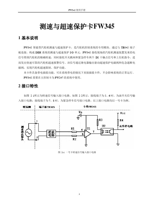
2接口特性如图 2-1所示为转速信号输入接口电路。
如图 2-2所示,接线端子为5、6时,为油开关信号输入接口电路;接线端子为7、8时,为紧急停车信号接口电路。
以上接口电路均以一号卡为例。
图2-1 一号卡转速信号输入接口电路1图 2-2 一号卡油开关(紧急停车)信号输入接口电路如图 2-3所示,端子为25、26时为超速103%保护“三选二”报警输出接口电路,端子为27、28时为超速110%保护“三选二”报警输出接口电路。
图2-3 3选2 报警输出接口电路3使用说明卡件结构简图,如图 3-1所示:2图3-1 FW345结构简图3.1LED指示灯说明表 3-1 指示灯说明名称含义状态FAIL 卡件故障指示灯正常情况下灭。
当卡件故障或者复位时,FAIL 灯亮。
端子板24V未接,FAIL灯也会点亮RUN 卡件程序运行指示灯正常情况下RUN闪烁WORK 卡件工作指示灯正常情况下常亮COM 卡件通讯指示灯正常情况下闪烁POWER 卡件内部24V指示灯正常情况下常亮SLIP 开关跳闸指示灯跳闸点亮,反之灭TRIP 紧急停车指示灯系统紧急停车点亮,反之灭103A 103%报警输出第一路报警时点亮,反之灭103B 103%报警输出第二路报警时点亮,反之灭110A 110%报警输出第一路报警时点亮,反之灭110B 110%报警输出第二路报警时点亮,反之灭33.2跳线3.2.1跳线说明表 3-2 FW345跳线设置J501 程序下载接口,下载时连接下载线。
硕方线号机说明书
TB345使用手册
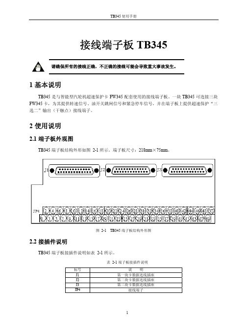
2.1 端子板外观图
TB345 端子板结构外形如图 2-1 所示。端子板尺寸:218mm×75mm。
图 2-1 TB345 端子板结构外形图
2.2 接插件说明
TB345 端子板接插件说明如表 2-1 所示。
标号 J1 J2 J3 JP4
表 2-1 端子板接插件说明
说明 第一块卡数据连线插座 第二块卡数据连线插座 第三块卡数据连线插座
冗余 24V 电源 A 路 冗余 24V 电源 B 路
33~48
NC
不接
49
保护地端子
接大地
50
保护地端子
接大地
3
TB345 使用手册
2.5 TB345 端子板“三选二”逻辑说明
图 2-5 报警输出三选二逻辑说明
M1,M2,M3 分别代表三块 FW345 卡件;N0103A 和 N0103B 分别代表一块 FW345 卡件的两路 103%报警输出;110%报警输出“三选二”逻辑与此相同。
3 资料版本说明
资料版本号
表 3-1 版本升级更改一览表 更改说明
TB345 使用手册(V1.0)
4
15、16
现场来紧急停车信号
紧急停车信号(干触点),触点闭合表示紧急停车
三
17、18
现场来转速信号
号 卡
19、20 2波)输入点,信号不分正负。 空
油开关跳闸信号输入端(干触点),触点闭合表示跳闸
23、24
现场来紧急停车信号
紧急停车信号(干触点),触点闭合表示紧急停车
TB345 使用手册
接线端子板 TB345
请确保所有的接线正确,不正确的接线可能会导致重大事故发生。
1 基本说明
思科RV345 RV345P路由器快速入门指南说明书
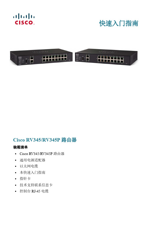
快速入门指南Cisco RV345/RV345P 路由器装箱清单•Cisco RV345/RV345P 路由器•通用电源适配器•以太网电缆•本快速入门指南•指针卡•技术支持联系信息卡•控制台 RJ-45 电缆欢迎Cisco RV345/RV345P 系列路由器可为小型企业提供可靠的互联网访问连接。
Cisco RV345/RV345P 系列的所有型号均支持两种连接方式,一种方式是选择一家互联网服务提供商,并通过使用负载均衡技术提供高性能连接;另一种方式是选择两家不同的服务提供商,以便确保业务连续性。
•双千兆以太网 WAN 端口支持负载均衡,并能确保业务连续性。
•千兆以太网端口不仅经济实惠,而且性能优越,既可快速传输大文件,又能同时支持多用户使用。
•双 USB 端口支持 3G/4G 调制解调器或闪存驱动器。
此外,WAN 还支持故障切换到连接至 USB 端口的 3G/4G 调制解调器。
•通过 SSL VPN 和站点间 VPN 可提供高度安全的连接。
•状态数据包检测 (SPI) 防火墙和硬件加密功能可提供强大的安全保护。
•RV345 型号具有一个 16 端口 LAN 交换机.•RV345P 型号具有一个 16 端口 LAN 交换机,其中前 8 个端口(LAN 1-4和9-12)是 PSE (PoE)端口。
本快速入门指南介绍 Cisco RV345/RV345P 的安装方法以及基于 Web 的设备管理器启动方法。
1安装 Cisco RV345/RV345P为防止设备过热或受损,请注意以下要求:•环境温度 — 请勿在环境温度超过 40°C (104°F) 的区域中使用本设备。
•通风 — 请确保设备周围通风良好。
若以壁挂方式安装防火墙,请确保散热孔朝向侧面。
•电路过载 — 接通设备电源不得造成电路过载。
•机械负载 — 请确保设备保持水平、平稳且牢固,以免出现任何危险情况,并防止其出现滑动或移位。
FW342使用手册

6 故障分析及维护方法
序号 1 2 3
故障特征 COM 灯暗 FAIL 灯快闪 FAIL 灯常亮
表 6-1 故障分析及维护方法
故障原因 和数据转发卡无通讯 卡件复位,CPU 没有正常工作
2 接口特性
FW342 的接口示意图如下图所示:
图 2-1 FW342 卡接口示意图
3 使用说明
FW342 卡件的外形图如图 3-1 所示:
1
FW342 使用手册
图 3-1 FW342 卡件外形图
3.1 LED 指示灯说明
卡件面板上的 LED 指示灯说明如表 3-1 所示。
表 3-1 指示灯说明
LED 指示灯 FAIL(红) RUN(绿) WORK(绿) COM(绿) POWER(绿)
图 3-2 长脉冲加步进脉冲控制算法原理
3.5 PAT 卡自学习功能
获准 PAT 卡具备自学习功能,自学习功能主要用于控制参数的设定,使用户很快了解外接阀门 的相关特性并快速完成软件中部分参数的设定。
将电动执行机构的信号线、控制线和卡件连接好之后,点击自学习按钮,卡件将会启动自学习 模块。卡件自学习过程主要分两步进行:第一步是输出长驱动脉冲使电动执行机构达到匀速运动状 态:阀位连续变化超过 5%之后截断输出,并开始计时直到阀位稳定。累计时间即阀位的稳定时间, 这段时间阀位变化的修正值则是电动执行机构的阈值。第二步是卡件输出 10ms 短脉冲判断阀位是否 变化,如果没有变化则输出 20ms 的短脉冲,这样以 10ms 的步进递增,输出 30ms、40ms、50ms …… 的短脉冲,直到阀位有变化。记录下脉冲时间长度即最小动作步进,此时阀位变化的修正值就是电 动执行机构死区。
3 4英寸数字扭力适配器说明书

3/4"Drive Digital TorqueAdapterWhen unpacking your new digital torque adapter and related parts& accessories,please inspect it carefully for any damage that may have occurred during transit.If you have any questions,or require assistance with damaged or missing parts,please contact our factorycustomer service department at:1-800-386-0191Please have the serial number,model number,and date of purchase available for reference when calling.This instruction manual is intended for your benefit.Please read and follow the safety,installation,maintenance and troubleshooting steps described within to ensure your safety and satisfaction.The contents of this instruction manual are based upon the latest product information available at the time of publication.Due to continuing improvements,actual product may differ slightly from the prod-uct described herein.Tools required for assembly and servicing are not included.INTRODUCTIONAfter opening the carton,unpack your new digital torque wrench adapter and related parts &acces-sories.Please inspect it carefully for any damage that may have occurred during transit.Please check it against the photograph on carton.If any parts are missing,please call factory customer ser-vice at 1-800-386-0191.UNPACKING &INSPECTIONDo not operate this tool if damaged during shipment,handling or misuse.Do not operate the tool until the parts have been replaced or the fault rectified.Failure to do so may result in serious per-sonal injury or property damage.All damaged parts must be repaired or replaced asneeded prior to operating this tool.Check to see that all nuts,bolts and fittings are secure before putting this tool into service.If you have any questions,or require assistance with damaged or missing parts,please contact our factory customer service department at:1-800-386-0191Please have the serial number,model number,and date of purchase available for reference whencalling.WARNING -RISK OF FLYING PARTICLESREAD THIS MANUAL COMPLETELY BEFORE USING THE DIGITAL TORQUE ADAPTER•To insure accuracy,work must not move in angle mode.•For personal safety and to avoid adapter damage,follow good professional tool and fas-tener installation practices.•Periodic recalibration is necessary to maintain tool accuracy.USERS AND BYSTANDERS SHOULD ALWAYS WEAREYE PROTECTION•Besure all components,including adapters,extensions,drivers and sockets are rated to match or exceed the torque being applied with tool.•Observe all equipment,system and manufacturer’s warnings,cautions and procedures when using this adapter.•Always use the correct size socket for the fastener being torqued.•Do not use damaged sockets,showing signs of wear or cracks.•Always replace damaged fasteners before applying torque.WARNING -Electrical Shock Hazard•Electrical shock can cause injury.•Plastic handle is not insulated.•Do not use on live electrical circuits.Over-torquing can cause breakage.An out of calibration torque wrench can cause part or tool breakage.Broken hand tools,sockets or accessories can cause injury.Excess force can cause crow foot or flare nut wrench slippage.IMPORTANT SAFEGUARDSIMPORTANT SAFEGUARDSto applying torque.•Never use this digital torque adapter to loosen fasteners as damage may occur.•Do not exceed the rated maximum torque value for the digital torque adapter as break-age and/or a loss of accuracy could occur.•Always verify the calibration of the digital torque adapter if you know or suspect its capac-ity has been exceeded.•Always pull-do not push-on the drive tool(ratchet)handle that is connected to the digi-tal torque adapter.•Adjust your stance to prevent a possible fall while applying torque.•Apply torque slowly and grasp the center of the handle.Do not apply load to the end ofthe handle.•Avoid applying excessive torque,turn the ratchet slowly and steadily as you apply torque.Pay attention to the LED light and sound indicators.•Never submerge the digital torque adapter in water or any other liquid.•If the tool gets wet,immediately wipe it dry with a soft,clean towel.•Do not expose this wrench to dust or sand as this could cause serious damage.•Use the digital torque adapter only for its intended purpose as described in this manual.•Do not use the digital torque adapter if it is not working properly or if it has suffered anydamage.•Do not disassemble the digital torque adapter.•Do not expose the digital torque adapter to extreme temperatures,humidity,direct sun-light.•Do not shake violently or drop digital torque adapter.•Do not use this tool as a hammer.•Position batteries in proper polarity.•Do not mix batteries of different type.•Never clean the digital torque adapter with soap or solvents.•Use a soft,dry,clean cloth to clean the digital torque adapter and LCD panel.•Do not apply excessive force to the LCD display panel.•Store in a clean dry place.•Keep this tool away from magnets.PRODUCT SPECIFICATIONSDrive size:3/4inchAccuracy:CW:±1%CCW:±2%Memory presets:10Display resolution:0.1NmOperation mode:Peak/TraceUnit selection:kg-cm,kg-m,lb-in,lb-ft,N-mBattery:AAA x2pcsAmbient temperature range:Operating:-10°C–60°C(13.9°F–139.9°F)Storage:-20°C-70°C(-4°F–157.9°F)Auto shut-off:80secondsTorque range:50-600Ft-lbs(67.8-813.5N-m)PRODUCT FEATURES•Digital torque readout.•Selectable for five torque units of measure:lb-ft,lb-in,kg-cm,kg-m and N-m.•+/-1%CW and +/-2%accuracy•Clockwise (CC)and counterclockwise (CCW)operation indicated on display.•Peak torque hold mode and Tracking torque mode selectable.•White LED backlight for easy reading.•Reverisble LCD display viewing orientation.•Multiple preset torque value indicators:audible buzzer,vibration alarm,red LED warning light.•Displays percentage of preset torque value attained.•Power saving automatic sleep mode activates after 3minues of inactivity.•Uses two (2)AAA size batteries.•Batteries,storage caseand calibration adapterincluded.LCD displaywithbacklight Extension bar ModeKEYBOARDUnitsPeak hold/TraceDigit shiftAdd valueMode The Titan Digital Torque Adapter displays fastener torque specification settings,torque readings and peak hold measurements.Buzzerpreset torque battery icon value of measure LCD DISPLAY INDICATORSWhen battery voltage drops below 2.6volts,a low battery warning icon willappear on the LCD display.When the battery voltage drops below 2.4volts,the low battery warning icon will begin to flash,indicating that immediate battery replacement isrequired.LOW BATTERY VOLTAGE INDICATIONBattery voltage under 2.4VPOWERING ON DIGITAL TORQUE ADAPTERPress Mode button to turn digital torque adapter on and activate auto-zeroing process.Auto-zeroing processNormal mode(Preset number 0shown)CAUTION:Make sure the displayed applied torque value is zero during the auto-zeroing period.Otherwise a torque offset will be included.Select 1of 10user programable memory presets.SELECTING MEMORY PRESETSSETTING PRESET VALUES4.Five different unit selections are available:kg-cm,k-gm,in-lb,ft-lb,and N-m.SELECTING UNITS OF MEASURENOTE:When you change units,any target torque setting you have already entered will now be displayed in the new unit value.SELECTING PEAK HOLD/TRACKING MODESPressIn Track mode -The display will register “real-time”torque as it is applied.This is useful when you are able to observe the digital display while applying torque to a fastener.Watching the torque value increase can assist you in applying torque evenly and safely,especially as you approach your target torque setting.FullyreleaseDisplay retains peak torque achieved.PEAK HOLD MODE OPERATIONPeak Hold ModePercent of Target torqueApplytorque activatesRelease torque to zero-out torquereading and then apply torque again.Select pre-setting:200kg-cm(in this example)Applytorque and hold2sec.Toggle screen from Auto mode to Manual mode.Continue applying torque until preset torque value In Peak hold mode,the digital display shows the maximum torque applied,which can be helpful for verifying that the correct torque was applied when the digital display is not visible during use.This mode is also handy when using the adapter to calibrate a torque wrench.TRACKING MODE OPERATIONTracking ModeAt50%of Target torque:•Percentage of preset torque value is displayed•Buzzer sounds:Bi---Bi---Bi---•Select pre-setting:200kg-cmApply torque to reach preset torque value(200kg-cm in this example)At70%of target torque:At90%of target torque:At100%of target torque:•Percentage of preset torque value is displayed•Buzzer sounds:Bi-Bi-Bi-Bi•Red LED flashes:alert•Percentage of preset torque value is displayed•Buzzer sounds:BiBiBiBiBiBiBi•Percentage of preset torque value is displayedApplytorqueApplytorqueApplytorqueIn Tracking mode,the display will register torque as it is applied in real-time.This allows you to observe the digital display while applying torque to a fastener.Watching the torque value increase can assist you in applying torque evenly and safely,especially as you approach your target torque setting.1.Requires two (2)alkaline AAA batteries.2.Unscrew battery cover fastener with 2.5mm hex key wrench.3.Remove the battery cover.4.Remove the old batteries.5.Clean battery terminals.6.Install fresh batteries in the digital torque adapter (with the “+”sign ends away from the contact springs).7.Replace the battery cover and screw tight.Note•Remove batteries if stored for a long period of time.•DO NOT mix batteries by type,brand,or condition.•Oil,water,dirt and sweat can prevent a battery’s terminals from making electrical contact.Wipe both terminals before installing batteries.•Typical battery life is 2000uses.Battery disposalOnly dispose of batteries when they are fully discharged.DO NOT dispose of batteries in a fire.Dispose of expended batteries and packaging materials in an environmentally responsible manner.Press and hold Mode button for 2seconds to turn unit off.NOTE:This tool will automatically enter sleep mode after 3minutes of inactivity.BATTERYINSTALLATIONANDREPLACEMENT POWERING OFF DIGITAL TORQUEADAPTORPress and for 2seconds to toggle the orientation of the display readout.CHANGING ORIENTATION OFDISPLAYPressCALIBRATING A TORQUE WRENCH USING DIGITAL ADAPTER 1.Set your torque wrench to a value of approximately25%of its maximum capacity.For example,ifyour torque wrench has a maximum capacity of150lb-ft,set it to40lb-ft.2.Program the digital torque adapter for a torque value that matches the torque wrench setting.Inour example,you would set the adapter for40lb-ft.Ensure the adapter is in the“peak”mode as this will make it easy to reference actual torque versus the torque indicated on the wrench.3.Connect the pre-set torque wrench and the included calibration adapter to the digital torque adapt-er.Secure the calibration adapter in a bench vise.Ensure the calibration adapter is securely tight-ened in the vise.4.Turn the torque wrench smoothly and steadily,applying torque to the calibration adapter until yourtorque wrench reaches the preset value,either by“clicking”(micrometer style torque wrench),or displaying the desired setting(digital or dial torque wrench).5.Read the peak torque value shown on the digital torque adapter.Adjust your torque wrench andrepeat the procedure until the trque wrench and digital torque adapter show identical torque val-ues.PLEASE NOTEDisposalDo not dispose of this device in normal domestic waste.Observe the currently valid regulations.In case of doubt,consult your waste disposal facility.IMPORTANT-Service,repair and calibration are to be performed by Star-Asia USA,LLC only.Cali-bration by the user is recorded in the wrench and voids factory certification.Contact Star-Asia USA, LLC for information on calibration service.USER QUICK REFERENCE GUIDEMeasure Torque Presetting Target Torque90DAY LIMITED WARRANTY-STAR ASIA-USA,LLC POWER TOOLSStar Asia-USA,LLC(hereinafter“seller”)warrants to the original purchaser only,that this product will be free from defects in material or workmanship for a period of one year from date of purchase for home domestic use. Warranty PerformanceWarranty coverage is conditioned upon purchaser furnishing seller or its authorized service center with adequate written proof of the original purchase date.Products returned,freight prepaid and insured,to our factory or to an Authorized Service Center will be inspected and repaired or replaced,at seller‘s option,free of charge if found to be defective and subject to warranty.Defective parts not subject to normal wear and tear will be repaired or replaced,at our option during the above stated warranty periods.In any event,reimbursement is limited to the pur-chase price paid.Other than the postage and insurance requirement,no charge will be made for repairs or replacements covered by this warranty.Under no circumstances shall the manufacturer bear any responsibility for loss of the unit,loss of time or rental,inconvenience,commercial loss or consequential damages.There are no warranties which extend beyond the description of the face hereof.ExclusionsThis warranty does not cover parts damaged due to normal wear,abnormal conditions,misapplication,misuse, abuse,accidents,operation at other than recommended pressures or temperatures,improper storage or freight damage.Parts damaged or worn by operation in dusty environments are not warranted.Failure to follow recom-mended operating and maintenance procedures also voids warranty.Additional items not covered under this warranty:product failure caused by rain,excessive humidity,corrosive environments or other contaminants;cosmetic defects that do not interfere with product‘s functionality.This warranty shall not apply when:the product has been used for commercial or rental purposes;defects in mate-rials or workmanship or damages result from repairs or alterations which have been made or attempted by others or the unauthorized use of nonconforming parts;this damage is due to abuse,improper maintenance,neglect or accident;or the damage is due to use of the product after partial failure or use with improper accessories.Warran-ty does not apply to accessory items such as batteries.Seller will not be liable for:labor charges,loss or damage resulting from improper operation,maintenance or repairs made by persons other than a Star Asia-USA,LLC Authorized Service Center.The use of other than genuine Star Asia-USA,LLC Repair Parts will void warranty.Warranty DisclaimersNO WARRANTY,ORAL OR WRITTEN,OTHER THAN THE ABOVE WARRANTY IS MADE WITH REGARD TO THIS PRODUCT,ANY IMPLIED WARRANTIES OF SELLER REGARDING THIS PRODUCT INCLUDING BUT NOT LIMITED TO,THE IMPLIED WARRANTIES OF MERCHANTABILITY OR FITNESS FOR A PARTICULAR PURPOSE,ARE EXCLUDED.BUYER‘S OR USER‘S REMEDIES ARE SOLELY AND EXCLUSIVELY AS STATED ABOVE.STAR ASIA-USA,LLC SHALL IN NO EVENT BE LIABLE FOR INCIDENTAL,CONSEQUENTIAL,INDI-RECT,OR SPECIAL DAMAGES.IN NO EVENT,WHETHER AS A RESULT OF A BREACH OF CONTRACT, WARRANTY,TORT(INCLUDING NEGLIGENCE)OR OTHERWISE,SHALL SELLER‘S LIABILITY EXCEED THE PRICE OF THE PRODUCT WHICH HAS GIVEN RISE TO THE CLAIM OR LIABILITY.ANY LIABILITY CON-NECTED WITH THE USE OF THIS PRODUCT SHALL TERMINATE UPON THE EXPIRATION OF THE WAR-RANTY PERIODS SPECIFIED ABOVE.Limitations on Warranty DisclaimersAny implied warranties shall be limited in duration to one year from the date of purchase.In some states of the U.S.A.and in some provinces of Canada there is no limitation for how long an implied warranty is valid,so the aforementioned limitation may not apply to you.Star Asia-USA,LLC(hereinafter“seller”)warrants to the original purchaser only,that this product will be free from defects in material or workmanship for a period of one year from date of purchase for home domestic use. Distributed by Star Asia-USA,LLCP.O.Box58399,Renton,WA98058Consumer Service:800-386-0191e-mail:*****************©2013Star Asia-USA,LLC。
菲蚊豪达自动变速箱用户手册说明书
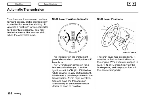
Automatic TransmissionYour Honda's transmission has fourforward speeds, and is electronicallycontrolled for smoother shifting. Italso has a "lock-up" torque converterfor better fuel economy. You mayfeel what seems like another shiftwhen the converter locks.Shift Lever Position IndicatorThis indicator on the instrumentpanel shows which position the shiftlever is in.The "D" indicator comes on for afew seconds when you turn theignition switch ON (II). If it flasheswhile driving (in any shift position),it indicates a possible problem in thetransmission. Avoid rapid accelera-tion and have the transmissionchecked by an authorized Hondadealer as soon as possible.Shift Lever PositionsThe shift lever has six positions. Itmust be in Park or Neutral to startthe engine. When you are stopped inD, 2, 1, N or R, press firmly on thebrake pedal, and keep your foot offthe accelerator pedal.DrivingSHIFT LEVERAutomatic TransmissionPark (P) — This position mechani-cally locks the transmission. Use Park whenever you are turning off or starting the engine. To shift out of Park, you must press on the brake pedal and have your foot off theaccelerator pedal. Pull the shift lever towards you, then move it out of Park.If you have done all of the above and still cannot move the lever out of Park, see Shift Lock Release on page 162.You must also pull the shift lever towards you to shift into Park. To avoid transmission damage, come to a complete stop before shifting into Park. The shift lever must be in Park before you can remove the key from the ignition switch.CONTINUEDDrivingAutomatic TransmissionReverse (R) — To shift to Reversefrom Park, see the explanation underPark. To shift to Reverse fromNeutral, come to a complete stop andthen shift. Pull the shift levertowards you before shifting intoReverse from Neutral.Neutral (N) — Use Neutral if youneed to restart a stalled engine, or ifit is necessary to stop briefly withthe engine idling. Shift to Park posi-tion if you need to leave the vehiclefor any reason. Press on the brake pe-dal when you are moving the shiftlever from Neutral to another gear.Drive (D) — Use this position foryour normal driving. The transmis-sion automatically selects a suitablegear for your speed and acceleration.You may notice the transmissionshifting up at higher speeds whenthe engine is cold. This helps theengine warm up faster.For faster acceleration, you can getthe transmission to automaticallydownshift by pushing the acceleratorpedal to the floor. The transmissionwill shift down one or two gears,depending on your speed.Over-Drive (O/D) ModeThe Over-Drive (O/D) is onwhenever you turn the ignition ON(II). You can turn it off by pressingthe O/D switch on the edge of theshift lever. The O/D OFF indicatoron the instrument panel next to theshift lever position indicator willcome on.DrivingAutomatic TransmissionWhen the Over-Drive is off the transmission selects only the first three gears, but not the fourth. Turn the O/D off to provide enginebraking when going down a steep hill.You can also avoid the transmission from cycling between third and fourth gears in stop-and-go driving.Second (2) — To shift to Second,pull the shift lever towards you, then shift to the lower gear. This position locks the transmission in second gear. It does not downshift to first gear when you come to a stop.Second gives you more power when climbing, and increased enginebraking when going down steep e second gear when starting out on a slippery surface or in deep snow.It will help reduce wheelspin.First (1) — To shift from Second to First, pull the shift lever towards you,then shift to the lower gear. With the lever in this position, the transmis-sion locks in First gear. By upshift-ing and downshifting through 1, 2, D,you can operate this transmission much like a manual transmission without a clutch pedal.Engine Speed LimiterIf you exceed the maximum speed for the gear you are in, the engine speed will enter into the tachometer's red zone. If this occurs, you may feel the engine cut in and out. This is caused by a limiter in the engine's computer controls. The engine will run normally when you reduce the RPM below the red zone.DrivingAutomatic TransmissionShift Lock ReleaseThis allows you to move the shiftlever out of Park if the normalmethod of pushing on the brakepedal and pulling the shift lever doesnot work.1. Set the Parking brake.2. Remove the key from the ignitionswitch.3. Place a cloth on the edge of theshift lock release slot cover on thesteering column. Remove thecover by carefully prying on theedge with a small flat-tippedscrewdriver (not included in thetool kit).4. Insert the key in the Shift LockRelease slot on the steeringcolumn.5. Push down on the key while youpull the shift lever towards youand move it out of Park to Neutral.SHIFT LOCK RELEASE SLOT6. Remove the key from the shiftlock release slot, then reinstall thecover.Depress the brake pedal andrestart the engine.If you need to use the Shift LockRelease, it means your vehicle isdeveloping a problem. Have thevehicle checked by your Hondadealer.DrivingParkingAlways use the parking brake when you park your vehicle. The indicator on the instrument panel shows that the parking brake is not fullyreleased; it does not indicate that the parking brake is firmly set. Make sure the parking brake is set firmly or your vehicle may roll if it is parked on an incline.If your vehicle has an automatic transmission, set the parking brake before you put the transmission in Park. This keeps the vehicle from moving and putting pressure on the parking mechanism in thetransmission — making it easier to move the shift lever out of Park when you want to drive away.If the vehicle is facing uphill, turn the front wheels away from the curb.If you have a manual transmission,put it in first gear.If the vehicle is facing downhill, turn the front wheels toward the curb. If you have a manual transmission, put it in reverse gear.Make sure the parking brake is fully released before driving away.Driving with the parking brakepartially set can overheat or damage the rear brakes.Parking TipsMake sure the windows are closed.Turn off the lights.Place any packages, valuables, etc.,in the cargo area or take themwith you.Lock the doors.Never park over dry leaves, tall grass, or other flammablematerials. The three way catalytic converter gets very hot, and could cause these materials to catch on fire.Driving。
eds345操作手册
EDS345操作手册
一、设备开启
1. 将设备连接到电源,确保电源稳定。
2. 按下设备正面的电源按钮,设备将启动。
二、用户登录
1. 启动后,将显示登录界面。
2. 输入已在设备上设置的用户名和密码。
3. 按下“登录”按钮,设备将进行身份验证。
三、打开应用程序
1. 通过设备的菜单或搜索功能找到所需的应用程序。
2. 选择并打开应用程序。
四、操作应用程序
1. 在应用程序中,您可以进行各种操作,如输入数据、查看结果等。
2. 请根据您的实际需求进行相应的操作。
五、数据保存
1. 在使用应用程序的过程中,建议您定期保存数据。
2. 点击应用程序中的“保存”按钮,以确保数据安全。
六、设备关闭
1. 当您完成所有操作后,请先退出所有应用程序。
2. 按下设备正面的电源按钮,设备将关闭。
注意:在进行任何操作之前,请确保您已了解设备的所有功能和限制。
如有疑问,请参考EDS345的用户手册或联系技术支持。
XS Wireless Digital Portable ENG Set 1 5 用户手册说明书
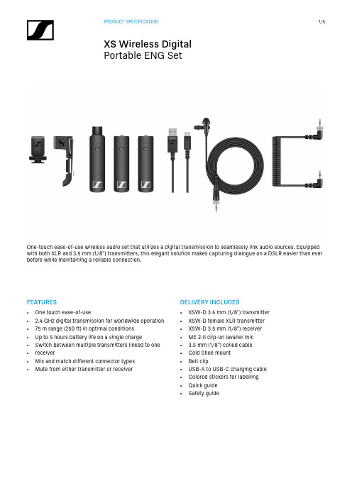
FEATURES• One touch ease-of-use• 2.4 GHz digital transmission for worldwide operation • 75 m range (250 ft) in optimal conditions• Up to 5 hours battery life on a single charge• Switch between multiple transmitters linked to one • receiver• Mix and match different connector types• Mute from either transmitter or receiver DELIVERY INCLUDES• XSW-D 3.5 mm (1/8") transmitter • XSW-D female XLR transmitter • XSW-D 3.5 mm (1/8") receiver • ME 2-II clip-on lavalier mic• 3.5 mm (1/8") coiled cable• Cold Shoe mount• Belt clip• USB-A to USB-C charging cable • Colored stickers for labelling • Quick guide• Safety guideOne-touch ease-of-use wireless audio set that utilizes a digital transmission to seamlessly link audio sources. Equipped with both XLR and 3.5 mm (1/8") transmitters, this elegant solution makes capturing dialogue on a DSLR easier than ever before while maintaining a reliable connection.SPECIFICATIONSUSB C interface for charging:Input voltage typ. 5.0 VCharging temperature0 °C - 60 °C (32 °F - 140 °F) Charging time typ. 3 hBattery pack:Cell type Li-IonNominal voltage 3.7 VCell capacity850 mAhOperating time up to 5 hAF characteristics:Codec aptX® LiveAudio frequency response 3.5 mm Jack/XLR:80 - 18,000 Hz6.3 mm Jack:10 - 18,000 HzAudio output max. 12 dBuSignal-to-noise ratio≥ 106 dBTHD< 0.1 %Audio latency< 4 msProduct properties:DimensionsXSW-D XLR FEMALE TX XSW-D MINI JACK TX XSW-D INSTRUMENT TX XSW-D XLR MALE RX XSW-D MINI JACK RX XSW-D INSTRUMENT RX XSW-D PEDALBOARD RX approx. 102 x 24 x 28 mm approx. 86 x 24 x 28 mm approx. 122 x 24 x 28 mm approx. 109 x 24 x 28 mm approx. 86 x 24 x 28 mm approx. 122 x 24 x 28 mm approx. 130 x 82 x 51 mmFrequency range2,400 - 2,483.5MHz Transmission power (EIRP)max. 10 mW Modulation GFSK with TDMAEnvironmental conditions:Operating temperature-10 °C to +55 °C(14 °F to 131 °F) Relative humidity95 % (non-condensing)PRODUCT VARIANTSXSW-D PORTABLE ENG SETME2-II, 3.5mm (1/8") transmitter,female XLR transmitter, 3.5mm (1/8")receiverArt. no. 508490Other sets:XSW-D VOCAL SETXS 1 handheld, female XLR transmitter,male XLR receiverArt. no. 508484XSW-D LAVALIER SETME2-II, 3.5mm (1/8") transmitter, maleXLR receiverArt. no. 508485XSW-D PEDALBOARD SET6.3mm (1/4") transmitter, pedalboardreceiverArt. no. 508486XSW-D PORTABLE LAVALIER SETtME2-II, 3.5mm (1/8") transmitter &3.5mm (1/8") receiverArt. no. 508488XSW-D PORTABLE INTERVIEW SETFemale XLR transmitter, 3.5mm (1/8")receiverArt. no. 508489XSW-D XLR BASE SETFemale XLR transmitter, male XLRreceiverArt. no. 508491XSW-D PRESENTATION BASE SET3.5mm (1/8") transmitter, male XLRreceiverArt. no. 508492XSW-D INSTRUMENT BASE SET6.3mm (1/4") transmitter, 6.3mm (1/4")receiverArt. no. 508493XSW-D PORTABLE BASE SET3.5mm (1/8") transmitter, 3.5mm (1/8") receiver Art. no. 508621ACCESSORIESXSW-D XLR FEMALE TXTransmitter with female XLR inputArt. no. 508494XSW-D MINI JACK TXTransmitter with 3.5mm (1/8") inputArt. no. 508495XSW-D INSTRUMENT TXTransmitter with 6.3mm (1/4") inputArt. no. 508496XSW-D XLR MALE RXReceiver with male XLR outputArt. no. 508497XSW-D INSTRUMENT RXReceiver with 6.3mm (1/4") outputArt. no. 508498XSW-D PEDALBOARD RXReceiver with 6.3mm (1/4") & maleXLR outputsArt. no. 508499XSW-D MINI JACK RXReceiver with 3.5mm (1/8") outputArt. no. 508500NT XSW-D PEDALBOARDPower supply for pedalboard receiverArt. no. 508647CL 353.5mm (1/8") coiled output cableArt. no. 508648CI 636.3mm (1/4") extension input cableArt. no. 508649XSW-D BELTPACK CLIPTransmitter belt clipArt. no. 508650XSW-D HOTSHOE MOUNTCamera mount for XSW-D receiversArt. no. 508651DIMENSIONSXSW-D XLR FEMALE TXUSB-CSennheiser electronic GmbH & Co. KG · Am Labor 1 · 30900 Wedemark · Germany · DIMENSIONSXSW-D MINI JACK TX | XSW-D MINI JACK RXUSB-C。
炜煌 针式打印机 说明书
台式打印机也有两种电平标准,可以根据下图所示进行 TTL 电平与 232 电平的转换,出厂设置为 RS232 电平:
RS232
RS232
TTL
接口引脚定义如下表所示: RS232 电平
TTL
TTL 电平
12
Tx 型 25 孔
2
T1 型 RJ45
Ax 型
25
信号 RXD
方向 说
明
入 打印机从主计算机接收数据
提供 LF 键和 SEL 键以及指示灯(绿灯) 5×10⁵行(MCBF) 工作温度:0~50℃,相对湿度:20~85%
2.1 并行接口连接
第二部分 操作说明
2.1.1 接口与引脚定义
本系列打印机并口与 CENTRONICS 兼容,支持 BUSY/ACK 握手协议,接口插座为 IDE 26 针插座。
并行接口插座引脚序号如下图所示:
串行口工作方式 3:一帧信息为 11 位,1 位起始位,8 位数据位,1 位校验位,1 位停止位。
④ 修改完之后需要重新上电启动。
2.2.3 串口例程
单片机控制打印机时汇编例程
; 北京炜煌串口打印机示例程序
; Nocky Tian ; 2006-07-18
BUSY ORG JMP
EQU 0000H start
*/
#include <intrins.h>
void PrintByte(unsigned char byte_data)
{
while( BUSY == 1 ){
}
PRINTER_DATA = byte_data;
nSTB = 0;
_nop_();
// 调整 nSTB 信号脉宽
单喷电子储纬器织机控制系统

三、 常见出错信息及排除方法
1. 信息提示和出错信息
............. ............ ...................... ...................................11
1.1 附录A:出错信息 .................. ............ ............... .................................. 11
有两种输入区域,修改方式也不一样:
编辑区
编辑区主要是可修改的参数类和数值输入类, 它们可以是:数字(十进制或十六进制)或字 符串(所有的ASCI 字符).它有两种修改方式:
1.数字可以直接用数字键盘输入,再用确认键
确认:用
键会自动进入修改模式。输完 一
位数字,光标会自动移到下一位数字。如果按
键,则输入无效,系统自动恢复为以前的
数值。使用 将所做的修改保存并将修改的目
标移到下一个。一旦按下确认键保存了所做的
修改,再按 键将无法恢复修改之前的值。
如果在当前屏幕上只有一个修改目标,则修改
完后此目标仍为下一个修改的目标。
数字输入区(第一种修改方式)
最高转数 7200 纬纱制动力 1
这是输入区 输完2,光标自动移到后一位数 字
最高转数 2_ 纬纱制动力 1
T
决定
移动光标到下一个位置
花型
T
决定
花型 TR2A 决定
花型 决定
TR2A
用同样的方法滚动翻找想输入的
出字错符
1
刹车关
结束修改模式并保存
选择区
在 选择区你可以通过一个列表,在里面选择 你 想选择的参数(如:开/关,高/低 等等)。 修改之前你必须按 键进入编辑模式,一个 上下翻的标志将会出现( )。你可以通过
- 1、下载文档前请自行甄别文档内容的完整性,平台不提供额外的编辑、内容补充、找答案等附加服务。
- 2、"仅部分预览"的文档,不可在线预览部分如存在完整性等问题,可反馈申请退款(可完整预览的文档不适用该条件!)。
- 3、如文档侵犯您的权益,请联系客服反馈,我们会尽快为您处理(人工客服工作时间:9:00-18:30)。
5.1 端子板外观图
TB345 端子板结构外形如图 5-1 所示:
图 5-1 TB345 端子板结构外形图 5
本卡件具备带电插拔功能,可在系统带电的情况下直接插拔卡件,不会影响系统的正常运行。 FW345 需要在主控制卡为 FW247 的系统中使用。
2 接口特性
卡件的接口电路如下图所示:
图 2-1 转速信号输入接口电路
图 2-2 油(真空)开关或紧急停车信号输入接口电路 1
FW345 使用手册
图 2-3 3 选 2 报警输出接口电路
110%报警输出 2 路
油开关跳闸信
DI 开关量 输入,干触
号(油开关跳 闸为 ON,未跳
为 OFF)
1路
点
紧急停车功能
(停车为 ON, 不停车为
1路
OFF)
隔离电压
EMC 指标
输入类型 配电
输入回路短 路电流 输入阻抗 隔离电压 ON 电阻
OFF 电阻
EMC 指标
现场侧和系统侧光电隔离,1000VAC, 50Hz,60s
分
33~48
NC
冗余 24V 电源 B 路 不接
49
保护地端子
接大地
50
保护地端子
接大地
6
FW345 使用手册
5.4 TB345 端子板“三选二”逻辑说明
图 5-2 报警输出三选二逻辑说明
M1,M2,M3 分别代表三块 FW345 卡件;N0103A 和 N0103B 分别代表一块 FW345 卡件的两路 103%报警输出;110%报警输出“三选二”逻辑与此相同。
FW345 使用手册
测速与超速保护卡 FW345
1 基本说明
FW345 智能型汽轮机测速与超速保护卡,是汽轮机控制系统的专用模块。通过与 TB345 端子板 连接,构成 DEH 系统的测速与超速保护 I/O 单元。FW345 接收现场的汽轮机测速装置发来的电信号 得到汽轮机的精确转速,同时接收开关跳闸和紧急停车两个 DI 干触点信号和上位机指令,进而发出 快速可靠的汽轮机超速报警信号。该信号通过继电器输出驱动超速保护电磁阀和危急遮断电磁阀, 实现汽轮机超速限制、保护功能。
排除方法
检查外配 24V 线路 可更换探头或适当调整探头和齿轮之间的间距 (为防止探头碰到齿轮,间距应不小于 0.9mm) 检查系统 5V 供电电压是否低于 4.5V,调高系
统 5V 电压,或者检查排除干扰源
在上位机中进行设定
8 资料版本说明
资料版本号 FW345 使用手册(V1.0)
表 8-1 版本升级更改一览表 输出时间
15、16
现场来紧急停车信号
紧急停车信号(干触点),触点闭合表示紧急停车
三
17、18
现场来转速信号
号 卡
19、20 21、22
不接 现场来油开关跳闸
转速信号(正弦波)输入点,信号不分正负。 空
油开关跳闸信号输入端(干触点),触点闭合表示跳闸
23、24
现场来紧急停车信号
紧急停车信号(干触点),触点闭合表示紧急停车
不接 现场来油开关跳闸
空 油开关跳闸信号输入端(干触点),触点闭合表示跳闸
7、8
现场来紧急停车信号
紧急停车信号(干触点),触点闭合表示紧急停车
二
9、10
现场来转速信号
号 卡
11、12 13、14
不接 现场来油开关跳闸
转速信号(正弦波)输入点,信号不分正负。 空
油开关跳闸信号输入端(干触点),触点闭合表示跳闸
3 使用说明
卡件结构简图,如图 3-1 所示:
图 3-1 FW345 结构简图 2
FW345 使用手册
3.1 LED 指示灯说明
名称 FAIL RUN WORK COM POWER SLIP TRIP 103A 103B 110A 110B
表 3-1 指示灯说明
含义 卡件故障指示灯 卡件程序运行指示灯 卡件工作指示灯
103 动作允许信号
0:允许 103 动作(默认值) 1:禁止 103 动作
5
OPCPRT
超速 110 动作禁止信 号
0:允许 110 动作(默认值) 1:禁止 110 动作
此处不建议把超速 110%保护功能禁止
6 OVSPEED
机械超速试验
0:不在机械超速试验(默认值) 机械超速试验状态
下,卡件把 110%保
供电 信号类型
型号 功能
5V 24V
通道数
AI 模拟量 正弦波信号,
输入
转速测量
1路
DO 开关量 103%报警输出 2 路 输出,继电 器(常开)
频率 信号幅度
齿数 测速周期 测量精度
隔离电压
EMC 指标
输出类型 配电 过电流
FW345
5V±5%,Imax<400mA
24 V±10%,Imax<200mA
槽位错位报警
0:无报警 1:有报警
模块上填写的槽位 号和组态不一致时
报警
14 COMERR 卡件通讯故障报警
0:无报警 1:有报警
功能块的说明请参见相关功能块的说明书或在线帮助,如本说明书中介绍的功能块说明 与功能块说明书中的不符请以功能块说明书为准。
FW345 在工程应用中,通常三块一组,在汽轮机上选三个采样点测转速,然后三选一或者三选 二后输出驱动现场设备。以下是一个工程项目中的部分程序,程序中采用了 SPEEDTST 模块。因为 该模块输出的是一个十倍转速的无符号整型值,在使用该转速时需要先转换成浮点型然后除以 10, 下图中用 UINT_TO_FLOAT 和 MUL_FLOAT 两个模块实现该功能。
25、26
OPC 动作输出
超速 103%保护“三选二”输出(干触点),触点闭合表示输出
27、28
遮断打闸输出
超速 110%保护“三选二”输出(干触点),触点闭合表示输出
29
24V 电源 A 正输入端
公
30
24V 电源 A 负输入端
冗余 24V 电源 A 路
共
31、
24V 电源 B 正输入端
部
32
24V 电源 B 负输入端
7
FW345 使用手册
表 6-1 SPEEDTST 模块管脚说明
管脚 编号
管脚名称
含义和用法
备注
1
RACK
2
SLOT
机笼号,指在 SCKey 中组态的机笼号 槽位号,指在 SCKey 中组态的槽位号
此处必须与组态一 致,否则卡件和系统
都不能正常工作
3
TNUM
测速齿常情况下灭。当卡件故障或者复位时,FAIL
灯亮。端子板 24V 未接,FAIL 灯也会点亮 正常情况下 RUN 闪烁
正常情况下常亮
卡件通讯指示灯
正常情况下闪烁
卡件内部 24V 指示灯 开关跳闸指示灯
正常情况下常亮 跳闸点亮,反之灭
紧急停车指示灯
系统紧急停车点亮,反之灭
103%报警输出第一路 103%报警输出第二路 110%报警输出第一路 110%报警输出第二路
1:在机械超速试验状态
护的值抬高到 112%
7 OILSLIP
保留
8
SPEED
9
FAIL
10 ALM103
十倍当前转速值,数据类型为无符号整数
测速通道故障
0:无故障 1:有故障
超速 103 输出
0:未输出 1:有输出
11 ALM110 超速 110 打闸输出
0:未输出 1:有输出
12
STOP
预留
13 SLOTERR
FW345 使用手册
标号 J1 J2 J3 JP4
表 5-1 端子板接插件说明
说明 第一块卡数据连线插座 第二块卡数据连线插座 第三块卡数据连线插座
接线端子
5.3 端子定义及接线
表 5-2 端子定义及接线
端子号
信号
说明
一
1、2
现场来转速信号
转速信号(正弦波)输入点,信号不分正负。
号 卡
3、4 5、6
8
FW345 使用手册
图 6-2 SPEEDTST 模块程序图
7 故障分析及维护方法
表 7-1 常见故障及维护方法
序号 1 2 3 4
故障特征 FAIL 灯亮 低频时卡件测不到
脉冲 卡件不断复位
103、110 报警未输出
故障原因
外配 24V 未接入卡件 探头产生的频率信号
幅值过小 5V 供电电压不够或 者卡件受到干扰。 上位机未设定 103、 110 报警允许输出
群脉冲
三级指标(1000V)
浪涌
三级指标(2000V)
干触点输入
卡件自配电 24V
Imax<3mA
8.2kΩ
现场侧和系统侧光电隔离,1000VAC,
50Hz,60s
<1 kΩ
>100 kΩ
群脉冲
三级指标(1000V)
浪涌
三级指标(2000V)
5 端子板 TB345 及接线说明
请确保所有的接线正确,不正确的接线可能会导致重大事故发生。
6 工程应用说明举例
FW345 作为智能型汽轮机超速保护模块,用法比较特殊。首先需要在 SCKey 中组态该卡件,但 是“IO 点”信息不在 SCKey 中组态,而通过自定义算法中的特殊功能块“SPEEDTST”实现上下位 机的数据交换。
