ASME取证设备检查表
设备检查表模板
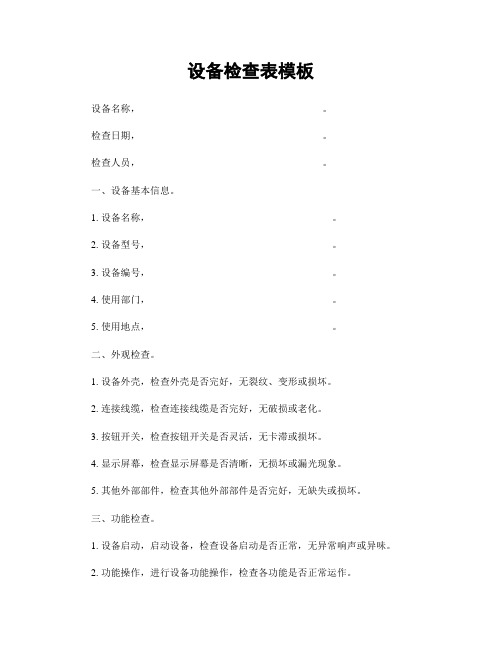
设备检查表模板设备名称,_____________________________________。
检查日期,_____________________________________。
检查人员,_____________________________________。
一、设备基本信息。
1. 设备名称,_____________________________________。
2. 设备型号,_____________________________________。
3. 设备编号,_____________________________________。
4. 使用部门,_____________________________________。
5. 使用地点,_____________________________________。
二、外观检查。
1. 设备外壳,检查外壳是否完好,无裂纹、变形或损坏。
2. 连接线缆,检查连接线缆是否完好,无破损或老化。
3. 按钮开关,检查按钮开关是否灵活,无卡滞或损坏。
4. 显示屏幕,检查显示屏幕是否清晰,无损坏或漏光现象。
5. 其他外部部件,检查其他外部部件是否完好,无缺失或损坏。
三、功能检查。
1. 设备启动,启动设备,检查设备启动是否正常,无异常响声或异味。
2. 功能操作,进行设备功能操作,检查各功能是否正常运作。
3. 设备运行,让设备运行一段时间,检查设备运行是否稳定,无异常故障。
四、安全检查。
1. 电源接线,检查电源接线是否牢固,无松动或短路现象。
2. 电气绝缘,检查设备电气绝缘是否良好,无漏电或触电风险。
3. 防护装置,检查设备防护装置是否完好,无缺失或损坏。
4. 使用标识,检查设备使用标识是否清晰,无模糊或褪色现象。
五、维护保养。
1. 清洁保养,定期清洁设备外部及内部部件,保持设备清洁。
2. 润滑维护,定期对设备运转部件进行润滑维护,保持设备正常运转。
ASME QC Manual Check List检查表

ASME BOILER & PRESSURE VESSELACCREDITATIONGUIDE FORASME REVIEW TEAMSFORREVIEW OF APPLICANTSFOR ASMECERTIFICATES OF AUTHORIZATION(A, M, PP, S, E, V, HV, H, HLW, H (Cast Iron), UD, UV, UV3, U, UM, U2, U3, RP, T, TD, TV)The American Society of Mechanical EngineersThree Park AvenueNew York, NY 10016A1.20-9/06 (1/11)INTRODUCTIONThis Guide is prepared for the use of ASME Review Teams. It is not intended to replace or interpret the requirements of the ASME Boiler and Pressure Vessel Code (B&PVC).In addition, to assist the ASME Review Team, this Guide will be provided to Applicants for ASME Certificates of Authorization for their use in cross referencing the paragraphs in their Quality Control (QC) Manual with the applicable control requirements of the Code.This Guide is based on Section I, Section IV, Sections VIII Divisions 1, 2 and 3, Section X, and Section XII of the B&PVC. The Guide is subject to revision based on changes made in the aforementioned Sections in the B&PVC.A Review must cover a QC Manual and its implementation. It is recognized that the scope of work, QC Manual, and Manual implementation will vary from Applicant to Applicant. Therefore, the ASME Review Teams are advised that all aspects of this Guide may not apply and that this Guide may not outline all possible aspects of each Review. The Manual need not follow the format of this Guide.Questions of possible need for Code interpretation raised by Review Teams shall be submitted to the ASME Director, Accreditation and Certification. When a request for an interpretation is to be submitted by an Applicant, the Team Leader shall advise the Applicant that all such inquiries must be submitted to the Secretary, Boiler and Pressure Vessel Committee, and that a copy of the inquiry and reply should be provided by the inquirer to the Applicant's Authorized Inspection Agency and cognizant Jurisdiction, if appropriate.Suggestions for revisions or clarification to this Guide should be directed to the ASME Director, Accreditation and Certification.A1.20-9/06 (2/11)REVIEW DEMONSTRATIONThe purpose of the Review Demonstration is to evaluate the Applicant’s Quality Control System (QCS) and its implementation. For evaluation of the QCS, the Applicant must demonstrate to current Code rules sufficient administrative and fabrication functions of the QCS to show that they have the knowledge and ability to produce the Code items covered by the QCS. Fabrication functions may be demonstrated using current work, a mock-up, or a combination of the two.While the Applicant must address each element of the QCS in the Code, the Applicant need only demonstrate those elements within the intended scope of activities that apply to their program.Demonstration Item1: An Applicant2 for a single Code Symbol Stamp must demonstrate on an item that will be fabricated for the requested type of Code Symbol.For Applicants requesting multiple stamps, it is not necessary to have a demonstration item with design calculations for each Code Section. An item fabricated to any one of the requested Code Symbols may be used as the demonstration item. However, if the demonstration item is not to the most stringent Code requirements, the Applicant must provide additional calculations or another documentation package that contains Code calculations to the most stringent Code requirements and administrative documentation to sufficiently demonstrate compliance with all aspects of the company’s QCS.For example, an Applicant for U & U2 Code Stamps could demonstrate their QCS on a Section VIII, Div. 1 pressure vessel including design. However, due to the nature of Section VIII, Div. 2 requirements, certification of a design report by a Registered Professional Engineer would need to be demonstrated.If computer calculations are to be used, the Applicant shall demonstrate that the computer program has the capability of producing acceptable calculations.If the demonstration item is based upon current work that is being fabricated to a previous Code edition, the Applicant shall address changes in the Code that would require different actions in the demonstrations to be in compliance with the current Code.1The demonstration item shall be based on the latest Code Edition/Addenda in effect at the time of the application.2This does not apply to an Engineering Contractor under Section I. For an Engineering Contractor Organization under Section I, without a fabricating facility, a physical demonstration item is not required. However, a design specification must be provided as well as additional administrative functions to demonstrate compliance with the organization’s QCS.A1.20-9/06 (3/11)QUALITY SYSTEM REVIEW CHECKLISTItem No. Quality Element andSubelementsQC ManualReferences1. 2.GENERAL QUALITY CONTROL SYSTEM REQUIREMENTS(a) QC System is documented in detail in a QC Manual that addresses all requirementsof the applicable Code Section and includes:(1) a cover sheet that contains the company name and physical address as it willappear on the requested Certificate of Authorization;Note: The cover sheet may also contain the effective date of the QC Manual, mailing address, phone number or other information desired by the Certificate Holder orApplicant.(2) a brief description of the products being fabricated and/or work beingaccomplished under the Code including applicability of QC System to shopactivities, field activities or both;(3) control features to demonstrate Code compliance;(4) Manual revision control system;(5) provision for review and approval of QC Manual to maintain it current;(6) provision for submittal of QC Manual revisions to the Authorized Inspector(AI) (ASME Designee for H (Cast Iron), T Class 3, or ASME DesignatedOrganization for V, HV UD, UV, UV3, TD and TV) for acceptance prior toimplementation including timely updating of all copies to reflect acceptedrevisions;(7) provision for the custody and control of the Code Symbol Stamps to preventloss or unauthorized use; and(b) In the case where the QC Manual exists in more than one language, at least oneversion is in English and identified as the authoritative version.Note: A glossary of terms is desirable from the standpoint of clarity if abbreviated titles of personnel and control documents are used throughout the QC Manual. This,however, is not mandatory.AUTHORITY AND RESPONSIBILITY(a) The authority and responsibility for QC by management is documented.Note: In practice, a Statement of Policy and Authority must be signed by a senior company official responsible for Code activities (e.g., President, Vice President, Plant Manager, etc.).A1.20-9/06 (4/11)1.1.1Cover Page1.1.1Preface 11.31.1.2; 1.1.31.3.15.6.1Preface 1 Preface 3 Preface 1; Section 2No. Subelements References3. 4.(b) The authority and responsibility of those in charge of the QC System are clearlyestablished and documented.(c) Persons performing QC functions have sufficient and well defined responsibility, theauthority, and the organizational freedom to identify quality control problems and to initiate, recommend and provide solutions.ORGANIZATION(a) An organization chart showing the relationship between management andengineering, purchasing, manufacturing, production, field assembling, fieldconstruction, inspection and quality control, as applicable, exists and reflects theactual organization.Note: The purpose of this chart is to identify and associate the various organizational groups with the particular function for which they are responsible. The Code does not intend to encroach on the Certificate Holder's right to establish and, from time to time, alter whatever form of organization the Certificate Holder considers appropriate for their Code work.DRAWING, DESIGN CALCULATIONS, AND SPECIFICATION CONTROL(a) Procedures exist which assure that the latest applicable drawings, designcalculations, specifications and instructions, required by the Code, as well asauthorized changes, are used for manufacture, assembly, examination, inspection and testing. Procedures include provision for(1) review of customer supplied documents for Code compliance;(2) the preparation, review, approval and distribution of drawings, calculations,and specifications;(3) [Applicable to U2 and U3 only]use of the user's Certified Design Specification including authorized changes;(4) [Applicable to U2 and U3 only]providing the Manufacturer's Certified Design Report including authorizedchanges;(5) [Applicable to U2 and U3 only]certification of Design Specification and Design Report by a registeredprofessional engineer; andA1.20-9/06 (5/11)Section 2 Preface 1; 2.2.2Fig. 2.1Section 33.13.2NANANANo. Subelements References5. 6.(6) [Applicable to V, HV, UD, UV, UV3, TD and TV only]new capacity certification tests are conducted when changes in design aremade which affect flow path, lift or performance characteristics.(7) [Applicable to T Class 3 only], provisions for Design Certified Engineer. MATERIAL CONTROL(a) Procedures for material control exist to assure that the material received is properlyidentified and has documentation, including, as applicable, required materialcertifications or material test reports, to satisfy Code requirements as ordered.(b) The material control system assures that only the intended material is used in Codeconstruction. For Section XII only, material shall satisfy the applicable modelappendices requirements.(c) If substitution of materials is allowed, the applicable procedures for control of thisactivity are documented, including designation of the individual authorized toapprove substitutions.(d) The title of the individual responsible for identifying the need for material testreports or certificate of compliance is designated.(e) The title of the individual responsible for performing a receiving inspection of Codematerials is designated.(f) Information to be provided to the receiving inspector concerning the characteristics tobe checked is documented.(g) A procedure exists for handling materials that are found to be nonconforming atreceiving inspection.(h) If further material testing is required to be performed at receiving inspection orduring manufacturing operations, the applicable procedures for control of thisactivity are documented.(i) Measures are established to assure the proper marking, handling and storage ofmaterials.EXAMINATION AND INSPECTION PROGRAM(a) Fabrication operations, including examinations and bursting test procedures (for HCast Iron) are described in sufficient detail to permit the AI (or the Certificate Holder in the case of H (Cast Iron), V, HV UD, UV, UV3, TD and TV) to determine at whatstages specific inspections are to be performed. Specifically:A1.20-9/06 (6/11)NANA4..1.24.3; 4.4 4.2.74.1.1; 4.1.2 4.34.3.3; 4.3.5 4.3.94.3.44.4; 4.55.1No. Subelements References(1) Provisions for the use of checklists, process sheets, travelers, etc., for listing ofexaminations and tests to be performed and for designation of inspectionpoints.(2) Such checklists, process sheets, travelers, etc, are made available to theInspector prior to the start of fabrication.(3) [Applicable to RP Only]A basic production flow diagram exists and includes in-plant inspection andcheck-off points and means of recording the same.(b) Material test reports or certificates of compliance, examination reports, test records,and other fabrication records are available to the Inspector.(c) Measures provide for transferring markings to assure traceability is maintained.(1) If a coded marking system is used, it is documented and acceptable to theInspector.(d) Measures assure that the Inspector is informed of approaching inspection points.(e) [Not applicable to H (Cast Iron), T Class 3, V, HV, UD, UV, UV3, TD and TV]AI concurrence is obtained for repairs to material.(f) [Not applicable to H (Cast Iron), T Class 3, V, HV, UD, UV, UV3, TD and TV]Measures are established to assure that a final inspection is performed to assure allspecified requirements have been met prior to obtaining AI's concurrence forapplication of the Code Symbol Stamp.(g) [Not applicable to V, HV, UD, UV and UV3]Measures are established to provide for the preparation, certification, anddistribution of the applicable Data Reports.(h) Measures are established to control field activities, when applicable.(i) [For operations under UG-90(c)(2), HG-515.4(b) or TS200.7]Documented procedures exist and are accepted by the Authorized Inspection Agency(AIA), Jurisdictional Authority, and ASME Designee.Note: Procedures should fully describe AI coverage of ASME Code work on all shifts. Also, percentage of AI time spent inspecting vessels or boilers that may not qualify forhandling under UG-90(c)(2), HG-515.4(b) or TS200.7 should be addressed.A1.20-9/06 (7/11)5.1.25.1.3NA4.3.84.54.5.55.2.26.4.4 d) 5.35.5 Section 13 NANo. Subelements References7.(j) [Applicable to H (Cast Iron) only]Examination and inspection of each boiler or boiler part shall be in compliance with Article 2 of Part HC.(k) [Applicable to H (Cast Iron) only]Hydrostatic tests are conducted as required in HC-410, and there are means ofidentifying acceptable boiler sections or parts.(l) [Applicable to RP only](1) Resin mixing procedures are specified.(2) Measures are established covering storage, issuance, handling, and disposal orresins, catalysts, fillers and pigments.(m) [Applicable to RP only](1)Proceduresexistcovering(i) assembly and fit-up of the pressure vessel and parts; and(ii) adhesive-bonding of components.(n) [Applicable to V, HV, UD, UV, UV3, TD and TV only]Provisions exist for testing pressure relief devices as described in PG-73.4, HG-401.4 and UG-136(d), UG-137(d), KR-340, TR210.4 and TR310.5.CORRECTION OF NONCONFORMITIES(a) A procedure exists for the correction of nonconformities. Where AI involvement isrequired by the Code, the procedure is agreed upon with the AI. The procedureprovides for(1) identifying those responsible for the resolution of nonconformities;(2) identifying and controlling further processing of nonconforming items untilfinal disposition;(3) documenting the nonconformance and its disposition; and(4) [Not applicable to H (Cast Iron), T Class 3, V, HV, UD, UV, UV3, TD and TV]informing the AI of nonconforming conditions.Note: A nonconformity is any condition which does not comply with the applicable rules of the Code, QC Manual or other specified requirements. Nonconformities must becorrected before the completed component can be considered to comply with theCode.A1.20-9/06 (8/11)NANANANANA Section 66.26.2.26.2.2; 6.3; 6.4 6.3; 6.4.3No. Subelements References8. 9.WELDING [Not applicable to H (Cast Iron) or RP](a) Welding conforms to requirements of Section IX and other Sections of the Code, asapplicable to the scope of work.(b) Those responsible for certifying PQR's and WPQ's are identified.(c) WPS's are available to the welder in the work area.(d) Measures assure continued welder qualification in accordance with Section IX.(e) Those responsible for assuring that only qualified welders are assigned to performCode welding are identified.(f) Measures provide for the storage and conditioning, as required, of coveredelectrodes.(g) Measures are established for the control, issuance and return of welding material toassure proper materials are used.(h) Measures are established for removing or inspecting tack welds.(i) Measures provide for the right of the AI [or ASME Designated Organization for V,HV, UD, UV, UV3, TD and TV] to require requalification of a welder or procedure for cause.(j) Measures provide for a system to identify work completed by each welder. NONDESTRUCTIVE EXAMINATION [Not applicable to H (Cast Iron) or RP](a) Provisions exist for identifying the appropriate NDE procedures applicable to thescope of Code work. These provisions assure that:(1) NDE personnel are qualified in accordance with the applicable Code Sectionrequirement;(2) NDE (UT, MT and PT) examinations are performed in accordance with writtenprocedures when required;(3) the AI [or a representative from an ASME Designated Organization for V, HV,UD, UV, UV3, TD and TV] can require requalification of an NDE examinationor procedure for cause;A1.20-9/06 (9/11)Section 7 7.07.1.57.1.4; 7.2.4 7.37.5.27.4.87.57.5.57.1.6; 7.2.6 7.5.3 Section 8 8.18.28.4No. Subelements References10.11.12.13.14.(4) UT reports and RT films, as applicable, are retained in accordance with theapplicable Code requirement(5) NDE equipment is calibrated.HEAT TREATMENT[Not applicable to H (Cast Iron) or RP](a) Controls provided to assure that heat treatment as required by the Code for the scopeof Code work is applied.(b) Measures are established to assure proper placement of thermocouples and use ofcharts.(c) When heat treatment is subcontracted, measures are established to assure thatprocedures are followed and that heat treatment charts are provided.(d) Means are provided for the AI [or a representative from an ASME DesignatedOrganization for V, HV, UD, UV, UV3, TD and TV] to satisfy them that Code heattreatment requirements are met, (e.g., review of furnace time-temperature records or other methods as appropriate).CALIBRATION OF MEASUREMENT AND TEST EQUIPMENT(a) A procedure exists for the calibration of examination, measuring and test equipmentused in fulfillment of applicable Code requirements.(b) Measures are established that assure calibration records are maintained and thatstatus indicators are used to indicate the current calibration status of equipment. RECORDS RETENTION(a) Procedures exist for the maintenance of Manufacturer's Data Reports, radiographsand records as required by the applicable Section of the Code.SAMPLE FORMS(a) Forms used to control functions relative to quality are included within the QCManual and their use explained in the text of the QC Manual.AUTHORIZED INSPECTOR [Not applicable to H (Cast Iron), T Class 3, V, HV, UD, UV, UV3, TD and TV](a) An inspection agreement is established with an ASME accredited AuthorizedInspection Agency.Note: For Section XII Class 2 this could be a qualified inspector.A1.20-9/06 (10/11)11.2; 11.38.5; Table 10.2.19.1.19.1.29.59.6Section 1010.1; 10.211.2; 11.3Section 14 Section 12 12.1.1QUALITY SYSTEM REVIEW CHECKLISTItem No. Quality Element andSubelementsQC ManualReferences15.(b) A controlled copy of the QC Manual is available to the AI at the plant or constructionsite where Code activities are being carried out.(c) The AI has access to all drawings, calculations, specifications, procedures, processsheets, repair procedures, records, test results, and any other documents as necessary for the AI to perform their duties.(d) Provisions exist for providing a liaison between the AI and theManufacturer/Installer.(e) Provisions exist for free access for the AI and the Inspection Supervisor to all areasinvolving Code activities.(f) Provisions exist to assure that all Code required inspections by the AI are performed. ASME DESIGNEE [Applicable to H (Cast Iron), V, HV, UD, UV, UV3, TD and TV only] (a) A controlled copy of the QC Manual is available to the ASME Designee or ASMEDesignated Organization, as applicable.(b) The ASME Designee or representative from an ASME Designated Organization hasaccess to all drawings, calculations, specifications, procedures, process sheets, repair procedures, records, test results, and any other documents as necessary for the ASME Designee to perform the review in accordance with the Code.(c) [Applicable to V, HV, UD, UV, UV3, TD and TV only]Provisions exist for the inspection of pressure relief valves as described in PG-73.3,HG-401.3, UG-136(c), UG-137(c), KR-330, TR210.3 and TR310.4.A1.20-9/06 (11/11)12.1.4 12.1.3 12.1.2 12.2.1 5.1; 5.2 NA NA NA。
特种设备(压力容器、管道、起重机等)检查表
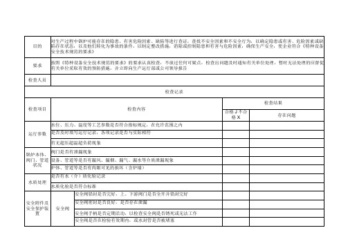
续页:锅炉使用情况(—月)检查记录
填表: 审核:
填表: 审核:
填表: 审核:
起重机械使用情况(—月)检查记录
对生产过程中锅炉可能存在的隐患、有害危险因素、缺陷等进行查证,查找不安全因素和不安全行为,以确定隐患或有害、目的危险因素或缺陷存在状态,以及他们转化为事故的条件,以制定整改措施,消除或控制隐患和有害与危险因素,确保生产安全,使企业符合《特种设备安全技术规范的要求》
按照《特种设备安全技术规范的要求》的要求认真检查,不放过任何可疑点,检查出问题及时通知有关单位处理,暂时无法处理的应督促有关单位采取有效的预防措施,并立即向生产运行部或公司领导报告
检查人员
审核:
填表: 审核:。
ASME取证质量手册

ASME取证质量手册目录章标题修订号日期─封面02003.07.15 A目录0 2003.07.15 B缩略词02003.07.15 C授权声明02003.07.15 1手册的管理02003.07.15 2组织机构02003.07.15 3图纸、设计计算和技术条件的管理02003.07.15 4材料管理02003.07.15 5检查和检验程序02003.07.15 6不一致品的处理02003.07.15 7焊接管理02003.07.15 8无损检验02003.07.15 9热处理02003.07.15 10计量和试验设备的校准02003.07.15 11记录保存02003.07.15 12授权检验师02003.07.15 13样表0 2003.07.15制定:日期:(质控部长)批准:日期:(总经理)同意:日期:(授权检验师)缩略词AIA: 授权检验机构AI: 授权检验师AIS: 主任授权检验师ASME: 美国机械工程师学会Code : ASME锅炉及压力容器规范第Ⅷ卷第1册,包括参考规范卷Code Items: 按照ASME规范要求设计、制造、检查、试验和检验的压力容器或零部件COL: 验收单Customer: 购买符合ASME规范要求产品的公司Customer Specification: 用户提供的相应技术说明Corporation: xxxxx公司JIC: 焊缝识别卡MAWP: 最大许用工作压力MDMT: 最小设计金属温度MDR: 制造厂数据报告MT: 磁粉探伤MTR: 材料测试报告NB: 美国锅炉压力容器检验师总部NCR: 不一致品处理通知单NDE: 无损检验PFC: 工艺流程图PQR: 工艺评定报告PT: 液体渗透探伤PV: 压力容器QC: 质量控制RT: 射线探伤QC Manager: 质控部部长UT: 超声波探伤Welder: 一般项目的焊工和焊接操作工WPQ: 焊工技能评定WPS: 焊接工艺规程WPEC: xxxxx公司WOPQ: 焊接操作工技能评定授权声明为了建造优质的ASME规范产品,确保产品符合规范和用户的要求,按照ASME锅炉压力容器规范第Ⅷ卷第1册,无锡市石油化工设备有限公司(WPEC)建立了相应质量控制体系。
asme样表册资料汇编

Exhibit No. List of Exhibits Rev. No. DateIV-1 CODE EDITION/ REVIEW CHECK LIST规范核实表0 Apr.08, 2012 IV-2 LIST OF MANUAL HOLDER 手册持有人清单0 Apr.08, 2012 2-1 Letter of Transmittal传送函0 Apr.08, 2012 2-2 Deliver & Receiving Note文件发放接收单0 Apr.08, 2012 3-1 Requisition of Material材料采购申请单0 Apr.08, 2012 3-2 Requisition of Welding Material焊接材料采购申请单0 Apr.08, 2012 3-3 Material Substitute Requisition材料代用申请单0 Apr.08, 2012 3-4 Label for Inspection待检标签0 Apr.08, 2012 3-5 Accepted Label合格标签0 Apr.08, 2012 3-6 Unaccepted Label不合格标签0 Apr.08, 2012 Material Receiving Inspection Record (Steel Plate)3-7 (a)0 Apr.08, 2012材料(钢板)进厂检验记录Material Receiving Inspection Record (Steel Pipe)0 Apr.08, 2012 3-7 (b)材料(钢管)进厂检验记录Material Receiving Inspection Record (Welding Material)0 Apr.08, 2012 3-7 (c)材料(焊材)进厂检验记录Material Receiving Inspection Record (Flange)0 Apr.08, 2012 3-7 (d)材料(法兰)进厂检验记录3-8 Material Request材料领料单0 Apr.08, 2012 3-9 Requisition Form of In-stock Material使用库存材料征询单0 Apr.08, 2012 3-10 Head Forming Inspection Record封头成型检验记录0 Apr.08, 2012Pressure Test Report (Hydrostatic, Pneumatic)0 Apr.08, 20124-1压力试验检验报告(水压、气压)4-2 Check Off List 工艺流转卡0 Apr.08, 2012 4-3 Name Plate 铭牌0 Apr.08, 2012 4-4 Visual and Dimensional Examination Report 外观及尺寸检验报告0 Apr.08, 2012 5-1 Non-conformity Report (NCR) 不合格品报告(NCR)0 Apr.08, 2012 5-2 Waiting for Disposition待处理0 Apr.08, 2012 6-1(a) Weld Summary Sheet焊接汇总表0 Apr.08, 20126-1(b) Welding Work Continuously Record焊接连续工作记录表0 Apr.08, 2012 6-2(a) Qualified Welder List合格焊工人员名单0 Apr.08, 2012 6-2(b) Qualified Welding Operator List合格焊接操作工名单0 Apr.08, 2012 6-3 Joint Identification Card焊缝分布图0 Apr.08, 2012 6-4 Welding Material Request焊材领用单0 Apr.08, 2012 6-5 Welding Repair Process Chart补焊返修工艺卡0 Apr.08, 2012 7-1 NDE Examiner Qualification Record无损检测人员资格鉴定记录0 Apr.08, 2012 7-2 List of Certified NDE personnel已有人员资格表0 Apr.08, 2012 7-3 Vision Examination Record 视力检查记录0 Apr.08, 2012 8-1 Heat Treatment Process Instruction热处理工艺卡0 Apr.08, 2012 8-2 Heat Treatment Report热处理报告0 Apr.08, 2012 9-1 Master List of Calibrated Instruments校正仪表总清单0 Apr.08, 2012 9-2 DO NOT USE禁用标签0 Apr.08, 2012 9-3 Calibration Sticker校正标签0 Apr.08, 2012 10-1 ASME Products List ASME产品清单0 Apr.08, 2012 10-2 NB Number Log NB编号登记表0 Apr.08, 2012Quality Control Manual Exhibit: IV-1 Rev: 0规范核实表CODE EDITION REVIEW CHECK LISTASME规范章节ASME CODESECTION 版本EDITIONLIST NO: 文件号是否修改REVISIONYES / NO有关文件DOCUMENT CONCERNEDⅡPART A PART B PART C PART D ⅤⅧ, DIV.1ⅨCOMMENTS备注:签发人PREPARED BY QA Manager签发日期ISSUED DATEQuality Control Manual Exhibit: IV-2 Rev:0手册持有人清单LIST OF MANUAL HOLDER签发日期Issued Date:签发人Prepared by QA Manager文件名称Document Name 版本号/修改号Ed./Rev.文件号Document No:版本(中文/英文)Version (Chinese/English)文件持有人清单(Signature List)分发号DistributionNo持有人姓名Holder’s Name持有人职务Title of Holder签名Signature日期Date回收Return*一旦收到新版本,控制副本的旧版本应退回。
化工厂常用PSSR检查表国外

PSSR Checklist Example A-1 PSSR清单示例A-1PSSR Checklist Example A-2PSSR Checklist Example A-3ATTACHMENT A - PROCESS PRE-STARTUP SAFETY REVIEW CHECKLISTAREA OR PLANT UNDER REVIEW:DATE:LIST OF PSSR TEAM MEMBERS:Instructions for using this form:1. Review the entire checklist and mark a check in column A to indicate an item or area to be included in the review.2. If there are issues to be resolved after the initial review, complete Attachment B - PSSR Potential Issue – Finding Form3. For each item or area with a check in column A, place a check in column B when the item or area has been satisfactorily reviewed or a potential problem has been resolved.Column A Include Column BCompletedCategory/PSSR Item to EvaluateLocation and layoutSite ConditionsDrainageFlood control/protectionPrevailing windAir or water pollution exposuresOther site conditions requiring attentionSoil protection in storage, materials handling &process areasNearby operationsHazards fromHazards toTrafficVehicular/railroad/pedestrianClearances, hazardsAdequacy of traffic signsSecuritySpecial requirements imposed by new facilityStorage and handling of chemicalsBuried pipes, tanks or chemical sewerLeak detection and containmentAbove ground storage tanksAdequate secondary containment providedOperating and maintenance access adequate andsafeAdequate and accessible manwaysUnobstructed pressure/vacuum relief ventsManifolding of vents reviewedDocumented vent sizing basis (process safetymanuals)Include CompletedWinterization (including instrument connections)Adequate lightingLabeling, placarding of hazardsOther installation detailsFlammable and combustible liquidsTank placement and spacing adequateSteel supports requiring fireproofingFlammable liquid breather vents provided withflame arrestors or conservation ventsNo flame arrestors on emergency relief ventsSafe vent discharge locationsVapor-space ignitions hazardsCorporate recommended/approved fire protectionsystems in placeFlammable gases or liquefied flammable gassesCorporate recommended/approved fire protectionsystems in placeBulk dry chemicalsDust explosion potential addressedTanks truck and railcar unloading and loading stationsSpill containment and safe impoundingAccess platform safetyLighting adequateGrounding cablesFixed unloading pump and backflow preventerEmergency stop button locationConnections lockable and closedPlacarding of hazardsRemotely operated emergency stop valve forvehicles carrying hazardous materialsFusible-link fire valve on vehicles with bottomunloading of flammablePortable fire extinguisher at ground level orflammableSafety shower and eyewash unitsRecommended fire protection systems in placeElectricalProcessGeneral workplaceSafe operator accessBuilding exits markedLighting adequateSafety shower and eyewash unitsAccessibleLocated on each deckLocated in control roomPortable fire extinguishersInclude CompletedAccessibleLocated on each deckLocated in control roomHuman FactorsLabeling of equipment, piping, critical valves, fieldinstruments, switchesLocation of field instrumentsSampling pointsOperator task safetyOperator task ergonomicsOpportunities for operator errorNon-routine tasksChemical Exposure HazardsPotential exposuresEngineering controls adequateBuilding ventilation/fresh air intakesToxic gas monitors, alarmsProtective equipment locationPlacardingProcess PipingConstruction appropriate for dutyMaterials quality assurance (including flange bolts),if critical, during constructionWorkmanship (for example, no short flange bolts)Routing satisfactoryAdequately supported and guidedAllowance for thermal expansion/no referencesNo small diameter connections vulnerable tobreakage/failureExpansion bellows properly installed/piping notable to move sideways/bellowedUndamaged during installationFlexible piping connectors correctlyinstalled/undamaged (for example, kinked) duringinstallationNecessary drains providedHazardous outlets plugged closedThermal (hydrostatic) pressure relief (includingheat-traced sections)Sight glasses and gauge glassesExternal corrosion protectionFreeze protectionInsulation adequate for personal protectionProtective flange coversApproved hoses and hose and connectors (noimprovisations)Process VentsInclude CompletedFlammable liquid breather vents provided withflame arrestors or conservation ventsTelltale pressure gauge or other indicator providedbetween rupture disc and relief valve where a discis installed below a relief valveDischarge piping from emergency pressure reliefdevices unrestricted by 90 degree ells,Excessive length or flame arrestorsProvisions such as drain holes to preventaccumulation of rainwater in discharge pipingDischarge piping adequately supported towithstand reactive forces of pressure ventingSafe vent discharge locationsManifolding of vents reviewedVent sizing basis; documentationDuctworkCleanoutsHeat Exchangers, JacketsVent, drainsThermal (hydrostatic) pressure reliefMaintenance access (tube bundle)MachineryGuardingLocal emergency stop buttonEmergency lubrication of critical machineryMaintenance provisionsLocal exhaust ventilation required for shaft sealsPumpsBackflow preventionConnecting piping adequately supported to limitforces on casingsSeal spray protectionIsolation for maintenancePreparation for maintenance (drain and ventprovided)ContainmentSpill containmentFire water runoffProcess Controls/Control RoomControl room inherent safety (vs. process hazards)VentilationEmergency lightingFire protectionField wiring securitySystem cable securityPower supplyOperator interface(s)Alarm systemsInclude CompletedEmergency shutdownCommunications - normal and emergencySoftware access/securitySoftware back-upUtilities Water SupplyNo municipal /potable water connections to theprocessSteam Boilers and DistributionFeedwater treatment chemicals handlingGas piping routingCombustion controlsHigh and low drum water level alarms providedBypass around Feedwater regulator accessiblefrom operating level and located whereDrum level gauge glass can be seenTwo independent low water level trips provided forunattended boilersDual safety relief valves in serviceRelief discharge piping adequately supported anddrainedNon-return valve on steam outletDistribution piping – see Process pipingCondensate drainage adequateCompressed Air SystemsNon-lubricated construction or non-flammablesynthetic lubricants used for compressorDischarge pressures above 100 psigElectricalTransformer locationMotor control center(s)Standby Emergency Utility SystemsReview provisions to satisfy proceeds safetyrequirementsWaste Handling/TreatmentInspect new facilities in the same manner asprocess facilitiesWarehouseFlammable and combustible liquidsForklifts and Motorized Hand TrucksTraffic safetyNon combustible fuelRecommended Fire-Protection Systems in PlaceMaintenance Area and ShopGeneralLocal exhaust ventilation provided for weldingLocker Room and Lunch RoomAdequate spaceInclude CompletedProvisions to protect contamination of food bychemicalsProcess Safety GeneralEmployee Participation StatementProcess Safety InformationReview of highly hazardous chemicals (HHC) andMSDSsBlock flow diagramMaximum inventoriesOperating limitsEquipment InformationP&IDsProcess Hazard Analysis (PHA) report(s)All PHA action items completedTraining planContractor work rulesPre-Startup Safety Review planMechanical Integrity planList of critical equipmentTesting program with scheduleHot Work Permit SystemSite Management of Change ProcedureIncident Investigation PlanEmergency Action Plan (EAP)Facility EAP writtenAre new chemical or process hazards or risks suchthat changes to existing EAP are required?Do new facilities create any new transportationemergency response needs and are such needs inplace? (Chemtrec update)Audit ScheduleOperating InstructionsOperating instructions clear and easily understoodInstructions adequate (complete)Material hazards adequately covered for rawmaterials, catalysts, intermediates,Products and by-productsHealth hazards and permissible exposure levels(PELs)Physical hazardsHandling precautions and safe handlingprocedures including PersonalProtective equipment (PPE) requirementsCorrective respiratory protection specifiedProcess hazards adequately describedThermal hazardsAny other hazardsInclude CompletedTabulation of process alarms, interlocks (bothsafety & non-safety) and trips includedAlarm and trip settings givenSpecific instruction included, or reference made toseparate instructions, forUnloading and loading of bulk materialsStep-by-step process proceduresprovided for each operating phaseincluding:Initial start-upNormal start-upNormal operationNormal shutdownEmergency operations includingemergency shutdownStart-up following emergency shutdownStart-up following a turnaroundNon-routine procedures (for example.equipment clean-out, equipmentpreparation for maintenance)Auxiliary equipment operationOperating limits clearly defined in step-by-stepproceduresControl ranges/limits specifiedConsequences of deviations givenResponses to deviations/abnormal conditionsspecifiedSafe hold points specifiedPPE caution statements incorporated in step-bystep proceduresUse of checklists as appropriateUp-to-dateAll pages show revision number and dateReviewed for correctnessApproved / signed by Department ManagerResponsible CareCommunity Awareness and Emergency ResponseCommunications training for keyemployeesEducation of employees on EAP, safety,health, and environmentalEducation of community on new processor changeOutreach to educate responders,government officials, EAPAssessment of potential risks toemployees from accidentsCommunication of emergency planninginformation to LEPCFacility tours for emergency respondersInclude CompletedProcess SafetyCurrent, complete documentation ofprocess design and operatingparametersCurrent, complete documentation ofhazards of materials and processUse of site management of changeprocedureUse of site incident investigationprocedureDocumented sound engineeringpractices consistent with recognizedcodes and standardsMechanical integrity programimplemented for new unit or processchangeEmployee Health and SafetyMedical surveillance program tailored tomeet needs of new process or changePersonnel change to Central SafetyCommittee neededPollution PreventionA quantitative inventory of wastesgenerated and releases to air, water andlandEducation of employees and public aboutthe inventory and impact evaluationDocumentation that waste generation isnot increased by, or is minimized in, thechange or new processDocumentation that waste and releaseprevention objectives were included thedesign of the new modified process &productsDistributionReview and training of distributionhazards with distributorsReview of transportation routing tominimized potential risksReview with corporate transportationdepartmentIndustrial HygieneNew substancesHealth careToxicity data availableAccident treatment planNeed for change in periodic medical examOccupational hygieneInventory of possible sources of exposureInventory means to restrict exposureMethods available to monitor exposureSuitable personal protection equipment availableInclude CompletedHearing ConservationNoise level monitoring needed/arranged for newoperationsEngineering and administrative controls adequatePermissible exposure limits for chemicalsubstancesAppropriate exposure monitoring and evaluationarranged to determine compliance with applicablePELsPELs for mixtures applied when two or morehazardous substances presentEngineering and administrative controls adequateLocal exhaust ventilation systemsPerformance of local exhaust ventilation systemsLocal exhaust ventilation systems placed oninspection and maintenance programControl of chemical substances posing a potentialoccupational mutagenic or carcinogenic riskAre materials used having control levels A, B, C, orD?In the plantIn the laboratoryHazard Communication ProgramLocation inventory of chemicals updatedHazardous materials identified in accordance withdefinitionsMSDSs on file and available to all employeesChemical containers labeled (or alternate means oflabel information provided)Piping labeledTrainingRespiratory protectionReview/confirm conformance with CorporateIndustrial Hygiene ProgramRespirator selection in accordance with selectioncharts and specified in writingPressure-demand SCBAsEmergency “escape only” respiratorsUser medical clearanceFacial hair policyInitial issues verified by supervisionFit testingReplacement of cartridges and canistersInspection and maintenanceBreathing air tested/taggedTrainingSmoking policy establishedLaboratory ControlProcess Laboratory Support Plan communicatedInclude CompletedStaffing adequateLaboratory facilities adequateGeneralEmergency exits markedEmergency lightingSafety shower & eyewashFire protectionLaboratory equipmentSuitable and adequateMaintenance provisions neededStorage and handling of chemicalsReagent storageSegregation adequate (oxidizers, acids)Flammable liquid storageRefrigerator for flammables explosion-proofSample storageSample and waste disposalCompressed gasesCylinder location safe (for example, awayfrom heat sources)Quantities limited to immediaterequirementsSeparation of flammable and oxidizersToxic gas use limited to small cylindersLocal exhaust ventilation for toxic gasesSCBAs available for toxic gasesPersonnel trained in SCBA use asneededLaboratory proceduresAnalytical procedures written and verifiedSampling procedures includedPPE requirements specifiedTraining completedIndustrial hygieneMaintenanceNecessary maintenance information in placeDesign drawings: for example as-built P&IDs,electrical schematics, isometric piping drawingPiping specificationsEquipment purchase ordersEquipment manualsVendor printsInitial inspection and test resultsResources adequateNeeds communicatedPlant personnelInclude CompletedContract maintenance (arrangements completed)Shop facilitiesSpecialized requirementsRequirements definedSkills availableEquipment availableProcedures developedTraining completedCertificate obtained and documentedMaintenance managementService contracts arrangedMaintenance management system in placeSpare partsRequirements defined by maintenance departmentProcurement completeStart-up needs on handStorage securityQuality assurance program in place for criticalequipmentMaterials of construction/quality of maintenancematerials and partsWorkmanshipPreventive maintenance/mechanical integrityprogram developedMachineryBoilers and pressure vesselsCritical equipment, vessels, piping, checkvalves, expansion bellows, flexible pipingconnectors, hoses definedCritical equipment inspection and testmethods and frequencies definedConservation vents, flame arrestors,PSEs, PSVs inspection and test methodsand frequenciesCritical instruments definedProof-testing frequencyProof-testing procedures, validityMaintenance of combustion safetycontrols on direct-fired equipmentInspection and testing acceptancecriteria developed and documentedTrainingOperations and MaintenanceInitial qualifications of personnel (knowledge andskills)Training program content vs. needsSafety orientation for new employeesGeneral safety trainingJob-specific trainingInclude CompletedBasic knowledge and skillsSpecialized knowledge and skillsGeneral process knowledgeMaterial hazards, MSDSsProcess hazardsProcess proceduresOperating limitsConsequences of deviationsResponses to deviations/abnormal conditionsEmergency proceduresField trainingLocation of:Emergency equipment, showers, alarmsFire-fighting equipmentLeak/spill preventionReporting, mitigationEmergency drillsCompliance with OSHA 1910.120 for hazardouswaste operationsNew emergency response training requirementsMeasurement of trainingEffectiveness/certification (when applicable)Formal documentation of trainingTeam assessment of training effectivenessCommissioningCommissioning plan and scheduleDetailed, step-by-step plan writtenPlan adequately reviewedResponsibilities clearly defined and understoodPlant verification of any equipment and systemscheck-out done by contractorConstruction inspection by plantConfirm line-by-line conformity to P&IDs verified byplant, including:Materials of constructionLocation of instrument elements/connectionsOrifice plate specifications and orientationRanges of local PIs and TIsAll local TIs have thermowellsIdentifies and relief pressure of PSEs & PSVsActuated valve failure modesEquipment internalsVessels and pipingStress relieving done and documented as requiredField radiography done and documented asrequiredPressure/Leak testing done and documentedInclude CompletedCleaned and flushed (instruments, control valves,check valves protected)Special commissioning requirements (such aschemical cleaning, passivating, or testing)Vents and pressure relief valvesShipping supports removed from conservationventsRelief pressure of PSVs verified by testFire protection systemsFire water systems inspection and commissionedFire water pump acceptance test(s) completed andwitnessedOther non-water fire protection system acceptancetest(s) completed and witnessed (for example, CO2or dry chemicalNew fire protection signaling systems and alarmscommissionedCopies of completed test forms forwarded toinsurance carrier and Corporate Risk DepartmentNew fire protection equipment, signaling systemsand alarms placed on regular inspection andtesting programsElectrical groundingResistance of building and equipment andgrounding systems measured <5 ohmsResistance to ground of all piping sections carryingflammable liquids and combustible powdersmeasured <5 ohmsVentilation systemsVentilation systems balancedPerformance of local exhaust ventilation systemschecked for conformanceMachineryAlignment checkedAbsence of excessive forces on pump casings andother equipment from connected pipingPre-startup screens installed in pump suctionsAgitator impeller securityLubrication systems functionalCooling systems functionalSeal flush systems functionalRotation checkedVibration measurementsPerformance testsOther baseline data collectionInstruments and control systemsProgram software checkedInstrument loop sheet index availablePneumatic lines blown cleanLoop checking done and documentedInclude CompletedInstrument calibrations done and documentedreview methodsAlarm and trip points set and documentedInterlocks (both safety & non-safety) testedDigital control system review and testsCombustion safety controls on direct-firedequipmentEquipment inspection, adjustment and testingdocumentedPunch listReview statusDaily updatePriorities with respect to start-up acceptableWater batchingPlan developedStart-upStart-up plan and scheduleWritten and reviewedProcedures for initial start-up specifically covered inthe operatingInstruction manual or under separate coverReviewed and approved if separateRaw materials supplyTechnical supportAdequateLines and limits of authority clearMaintenance supportIndustrial hygiene monitoringEquipment monitoringPerformance measurements and testsRegulatory ComplianceNew SubstancesReview of toxicity to environmentPersistency in the environmentPrevention of exposure to environmentDestruction of substance whennecessaryToxic Substances Control Act (TSCA)Project reviewed for any newrequirements which might be imposed onthe plant location under TSCATransportationNew transport operations adequatelyreviewed for compliance with allapplicable DOT (or equivalent)regulationsEmissionsInclude CompletedOperating permits obtained as directedby the site or corporate environmentaldepartmentsEffluentsNew operations covered within thepresent NPDES permit or a new permithas been obtainedHazardous wastesDetermined whether particular wastesqualify as hazardous wastes underfederal, state and/or local laws andregulationsOn-site storage, treatment and/ordisposal of hazardous wastesReviewed for compliance with applicablelaws and regulations, documentation?Off-site transportation and disposal ofhazardous wastes reviewed with wastecoordinator, documentation?PCBsReview equipment for PCB hazardouspropertiesSupplementary Checklist for New Plant SitesPlant SecurityAccessFencingVisitor controlsVehicle controlsRestrictions postedCommunicationsNormalEmergency back-upSafety programAccountabilityProgram conformance with CorporateSafety StandardsConformance with group safetystandardsFirst aid and emergency medicalresponseLocation procedures writtenTraining conductedIndustrial hygiene programAccountabilityProgram conformance with CorporateIndustrial Hygiene StandardsFire protection organizationLocation organizationLevel of protection established inaccordance with insurance requirementand Corporate Risk DepartmentInclude CompletedTraining conducted in accordance withstandardEquipment provided in accordance withstandardMunicipal fire department (or equivalent)Response time and capabilitiesconsistent with location needs and fireprotection organizationLiaison establishedFamiliarizationDrillsProcess Safety ManagementLocation coordinator appointedProgramTraining conductedATTACHMENT B - PSSR Potential Issue - Finding FormArea under review:Date of Review:List of Sub-Team Members:Instructions for using this form: For each issue, complete the information below. Electronically copy the blank fields as needed for each issue identified in Attachment A - Process PSSR checklist.Description of potential issue or area of concernAdditional information (for example, the issue’s criticality or a recommended solution)PSSR Checklist Example A-4DESIGN SAFETYREVIEW CHECKLISTDept.:MOC ID#:DATE:Project ID:INSTRUCTIONS: Check each question on the Yes or No line, or mark it N/A if not applicable. If an entire section of the checklist is not applicable, mark that section as N/A and no questions in that section need to be answered. No answers are considered deficiencies, and must be reported in writing to the Department Manager or designee and the change originator. This checklist is a guide to help identify possible deficiencies. All questions refer to the results, design and impact of the change, not broadly or in general to the system unaffected by the change. The reviewer is encouraged to look beyond the checklist for concerns which may be unique to the change and which may not be addressed here.YES NO N/A DSR CATEGORY SECTION/ITEMA. ADMINISTRATION1. Based on the current design, is the proposed change consistentwith the original Process Hazard Analysis (PHA) assessment?2. Does the design comply with corporate standards?3. Has the impact of the change on existing buildings beenconsidered? (That is, the design and location of new or modifiedequipment near occupied buildings, occupying a previouslyunoccupied building, and others.)4. Has any impact, beyond unit boundaries, associated with thischange been properly dealt with and/or communicated?5. Have exposures to existing buildings (including pipe racks andcable trays) been considered when siting new vessels, utilities,temporary/permanent buildings or sheds, and others?6. Have noncombustible materials or construction been used?B. MATERIAL SAFETY/REGULATORY STATUSHave the following change scenarios been considered for possibleToxic Substance Control Act (TSCA) applicability?a. Previously non-isolated intermediates being temporarily isolatedand/or held even for a short time, in non-hard-piped processequipment or in storage vessels (for example, drums).b. Previously non-isolated intermediates being held for anextensive period (for example, 24 hours or longer) in hard pipedprocess equipment.c. Material previously burned or disposed of as a waste isreprocessed or sold.d. Different reactants or catalysts or different feed ratios are beingused, thus producing different reaction products for TSCApurposes.e. Change in the components or reactants in a polymer from < 2 %to > 2 % of the dry weight of the polymer produced.f. The TSCA Inventory status of different catalysts or reactants isunknown. If any of the above change scenarios are about tohappen, contact the plant TSCA Coordinator immediately for an in-depth station of TSCA issues. Provide documentation of anyconcerns and their resolution.2. Have Material Safety Data Sheets (MSDS) or PreliminaryProduct Safety Data Sheets (PPSDS) been obtained for allchemicals to be handled, including isolated intermediates?(Consider changes in minor components of products and by-products)3. Has the potential for a hazardous chemical reaction in sumps and sewers been considered?4. Have all other potential product regulatory issues been addressed, for example, Department of Transportation (DOT), Federal Insecticide, Fungicide, and Rodenticide Act (FIFRA), Bureau of Alcohol, Tobacco, and Firearms (BATF), Food and Drug Administration (FDA) and ISO 9001?C. PRESSURE/VACUUM RELIEF(No relief devices in this project)1. Have new or modified safety relief device(s) or vent system(s) been designed in accordance with Plant Engineering and Site requirements?2. Has potential for external pressure (vacuum) from sudden cooling, condensing, pump-out, during clean-up or preparation of equipment for maintenance, or potentially submerged overflow line been addressed?3. Have only full-port valves been specified for use at the inlet and outlet of pressure/vacuum relief devices?4. Have any changes to safety relief device inlet or outlet piping been properly reviewed?5. Will adequate facilities (alarms, detectors, redundancy, and others.) be provided to minimize the risk of a relief device actuating due to equipment, instrumentation, or utility failure?6. Have the discharges of safety relief devices been located so as to avoid potential personnel injury and damage to associated equipment?7. Has the design included installation of the safety relief valve vertically?D. TEMPERATURE/REACTION1. Has potential for formation of unwanted by-products been adequately addressed?2. Has potential for loss of flow or reverse flow been adequately addressed?3. Have adequate provisions been made so that normally dilute but reactive materials CANNOT be concentrated or accumulated in unexpected areas (stagnant pipe/valves; utility systems; feed or reaction vessels, sewers, and others)?4. Is adequate freeze protection provided?E. VALVES AND PIPING1. Have the proper valve and piping specifications been used?2. Have cross-tied lines (pump headers, utility lines, betweenhigh/low pressures, and others.) been reviewed to minimize contamination potential and eliminate mixing of reactive chemicals?3. Have test methods and documentation requirements been specified to ensure the integrity of new and revised piping systems?4. Will sample points be properly configured for safe sampling of hazardous chemicals?5. Have all open ended valves and hand-operated ball valves been designed in accordance with environmental requirements (that is, NESHAPS covered materials such as benzene and formaldehyde) or plant standards?6. Have hot-taps been reviewed and eliminated where possible?7. Will necessary excess flow and back-flow prevention measures be provided?。
特种设备专项使用安全检查表
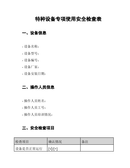
特种设备专项使用安全检查表一、设备信息
- 设备名称:
- 设备型号:
- 设备编号:
- 设备厂家:
- 设备安装日期:
二、操作人员信息
- 操作人员姓名:
- 操作人员工号:
- 操作人员培训情况:
三、安全检查项目
四、安全检查结果
- 检查人员签名:
- 检查日期:
- 检查结论:
五、安全检查意见和建议
- 安全检查意见和建议:
请注意填写以上信息,并逐一确认检查项目的情况。
如发现任何问题或隐患,请及时整改和处理,确保特种设备的安全使用。
填写结果后,由检查人员签名并记录检查日期,最后填写检查结论和提出的意见和建议。
新设备、工装和测试设备检查表

2.4 是否考虑了设备和工站状态的安灯探测
3.是否以根据顾客要求商定验收准则并将其文件化:(包括所有供应商)
3.1 新设备
3.2 新工装
3.3 新的测试设备(包括检查辅具)
3.4 在工装和/或设备制造商处是否会进行初始能力研究
5 测试设备的可行性和准确性是否已确定
在设备验收期间,是否考虑验证自动化系统之间的 6 通信(即顾客门户、数据收集、函数捕获、可追溯
10.1 是否分配了足够的资源来支持数据收集
10.2
是否有计划对所有尚未确认的防错设备进行100%检 查,直至确认完成
11
是否为每台设备创建了防错清单(需要完成APQP中 的其他过程)
12 是否会在加工工程进行初始过程能力研究
问题
是
否*
意见/需要采取的措施
责任人 截止日期
13 是否已识别影响产品特殊性的过程特性
性、软件兼容性)
7 设备和工装的预防性维护计划是否完整
a
关键工装和机器零件需要最小/最大库存水平-长交 货期零件
8
对于无法保留在库存中的交货时间较长的项目(零 件),是否制定了应急计划
9
新设备和工装的设置说明是否完整且易于理解,并 且采用作业指导书格式
10
设备供应商的工厂是否可以使用具备能力的量具来 进行初始过程能力研究
修订
制造设备是否有足够的产能来处理预测的生产数量 和服务数量
16 测试的产量是否足以提供足够的测试
17
测试设备是否经过验证并记录在案,表明其符合所 需的测量和测试范围
18 PFMEA是否已被理解并纳入工装和设备设计中
19 是否已根据顾客要求汇报变更情况
每个“ 否”项
ASME取证质量手册

ASME取证质量手册目录章标题修订号日期─封面02003.07.15 A目录0 2003.07.15 B缩略词02003.07.15 C授权声明02003.07.15 1手册的治理02003.07.15 2组织机构02003.07.15 3图纸、设计运算和技术条件的治理02003.07.15 4材料治理02003.07.15 5检查和检验程序02003.07.15 6不一致品的处理02003.07.15 7焊接治理02003.07.15 8无损检验02003.07.15 9热处理02003.07.15 10计量和试验设备的校准02003.07.15 11记录储存02003.07.15 12授权检验师02003.07.15 13样表0 2003.07.15制定:日期:(质控部长)日期:(总经理)同意:日期:(授权检验师)缩略词AIA: 授权检验机构AI: 授权检验师AIS: 主任授权检验师ASME: 美国机械工程师学会Code : ASME锅炉及压力容器规范第Ⅷ卷第1册,包括参考规范卷Code Items: 按照ASME规范要求设计、制造、检查、试验和检验的压力容器或零部件COL: 验收单Customer: 购买符合ASME规范要求产品的公司Customer Specification: 用户提供的相应技术说明Corporation: xxxxx公司JIC: 焊缝识别卡MAWP: 最大许用工作压力MDMT: 最小设计金属温度MDR: 制造厂数据报告MT: 磁粉探伤MTR: 材料测试报告NB: 美国锅炉压力容器检验师总部NCR: 不一致品处理通知单NDE: 无损检验PFC: 工艺流程图PQR: 工艺评定报告PT: 液体渗透探伤PV: 压力容器QC: 质量操纵RT: 射线探伤QC Manager: 质控部部长UT: 超声波探伤Welder: 一样项目的焊工和焊接操作工WPQ: 焊工技能评定WPS: 焊接工艺规程WPEC: xxxxx公司WOPQ: 焊接操作工技能评定授权声明为了建筑优质的ASME规范产品,确保产品符合规范和用户的要求,按照ASME锅炉压力容器规范第Ⅷ卷第1册,无锡市石油化工设备(WPEC)建立了相应质量操纵体系。
2021-2022收藏的精品资料ASME取证学习资料

ASME认证通过现场审核必须达到的基本条件:概括为“一个体系、三个有效、四个到位、九个资料”,即:建立一个能够满足ASME规范要求的质量控制体系;实现三个有效,满足ASME规范要求的示范产品有效、“设计—采购-制造-检验和试验”(包括设备、人员、工艺)过程有效、全过程的质量追溯证据有效。
工作过程为“四个到位”,即:职责到位;文件到位;运行到位;记录到位。
迎审前具备九个资料,即:体系文件3个(质量运行控制手册、程序文件汇编、质控记录);技术文件3个(设计包、焊接和无损探伤评审确认资料);证据3个,即示范产品以及示范产品制造现场硬件、演示、检验全过程的有效证据、开展ASME认证工作思路要点:1,首先要根据选定的认证产品需要,确定收集购买数得上配套标准。
包括:认证产品规范、认证产品所用材料、检验试验规范、焊接、热处理、NDE(无损检测)等特殊工序评审标准。
2,学好认证产品相关规范,掌握要点,编写质量体系控制文件,包括认证产品规范相关章节、质量手册及配套程序文件、刻录培训讲义、迎审工作要点。
通过学习、测试达到掌握要求。
3,选定认证的示范产品,开展设计开发并形成技术文件,针对选定的认证产品所对应的ASME规范,由设计人员根据产品设计方案进行技术交底及规范内容要求的解析培训。
4,根据体系和规范要求,分配职责、落实人员及工作要求。
一般讲思路就是“四个到位”,即职责/文件/运行/记录到位。
5,制造示范产品,焊接评审与NDE资格满足规范要求,制作达到临检状态;按工艺流程图、工序检验单形成过程有效记录。
6,按照ASME认证自检表开展自查、完善,达到体系和规范运行合格的要求。
ASME“U”钢印和证书取证计划AIA检验师到厂期间既是审阅文件、检验产品的过程,也是提供咨询服务过程。
其它时间变可随时咨询。
质量控制系统审查清单 ASME 认证审核要点及主谈人根据ASME 审查过程及质量系统管辖范围,现将质量控制系统审查清单列出,并指定了各项内容在审查时负责接受面谈的主谈人(被审人),各主谈人根据清单细化的内容条款,在“质量控制手册参考”栏目中列出各细化条款所依据的文件,以便在主谈过程中心中有数,能正确回答问题。
ASME质量检查质量控制交工表格
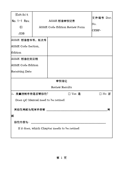
(Exhibit No.3-1 Rev. 0)(Exhibit No.3-2 Rev. 0)第7 页(Exhibit No.3-3 Rev. 0)第8 页4 Rev. 0)第11 页(Exhibit No.4-1 Rev. 0)第12 页(ExhibitNo.4-2 Rev. 0)第16 页第17 页第18 页Rev. 0)第19 页第20 页(Exhibit No.4-4 Rev. 0)第21 页(Exhibit No.4-5 Rev.0)No.4-6 Rev.0)第 26 页材料证明书审核章7 Rev. 0)Material Acceptance Label材料合格标签 〔Green 绿 色〕8 Rev. 0)Material Test Report Review Stamp第27 页第28 页Rev. 0)第29 页第30 页(Exhibit No.5-1 Rev. 0) 工艺流程图Process Flow Chart第31 页2 Rev. 0)第32 页第35 页(Exhibit No.5-3B Rev.0)第36 页NB 号码记录本NB Number Log BookNameplate for Code Item1)Nameplate for第八卷第一分册压力容器铭牌U✧The characters on nameplate shall not less than 4mm high.铭牌上的字符应不小于4mm高✧Theand shall be legible and readable.铭牌上的字符应缩凸进或凹起并应清晰易读。
〔Exhibit No. 5-6 Rev.0 〕hibit No.6-1 Rev.0〕停顿标签Hold Label〔Yellow 黄 色〕〔ExhibitNo.6-2Rev.0〕 返修/报废标签Repair/Reject Label〔 Red 红 色〕〔Exhibit No.6-3 Rev.0〕姓名Name:焊工号ID. No.:5 Rev. 0)第45 页Rev. 0)第46 页7 Rev. 0)第48 页No.8-1 Rev. 0)。
ASME 取证无损检测设备和器材准备清单
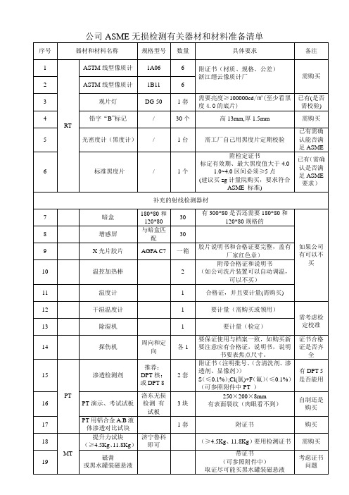
2、将黑度计型号、编号发给我。
3、将黑度片型号、编号、有效期及八个孔黑度值发给我(质证书扫描件发给我)。
4、取证用渗透剂、清洗剂、显像剂(带硫、卤素含量合格证书)的牌号(罐体上)、出厂编号
(在罐底上),要求与合格证统一,分别对应发给我。
(质证书扫描件发给我)
5.磁粉探伤用磁膏或罐,反差增强剂的牌号(罐体上)、出厂编号(在罐底上),要求与合格证统一,分别对应发给我。
(质证书扫描件发给我);
6、将白光照度计型号、编号、有效期发给我。
(质证书扫描件发给我);
(以上设备没有抓紧采购,尤其是黑度片、照度计、提升力试块,需要强制计量证书)。
ASME取证换证联检检查表

责任及控制方法:设计、材料、焊接、检查及检 中体现
验、无损检测、热处理、计量、MDR(生产数据报
告)及记录保存等
18. 申请“ UM” 证书时,应明确规定 CI 的责任与
职责、CI 的评定及认证要求及打 UM 钢印容器的
控制方法。(关于 UM 证书,不适用)
19.(关于 PP 和 S 证书,不适用)
为质控手册的组成部分
RT 规程(如适用)
PT 规程(如适用) 1.应经 III 级人员审批,AI 认可
没有规程,有 PT
2.必须按照 ASME 规范第 V 卷 T-150 要求向 AI 程序文件 进行
演示。PT 说明及演示报告应归档保存 3. ASME V 卷第 6 章中所列所有重要变素及非重
要变素均应在 PT 规程中列出,并明确说明各变
4.修订说明
控制中体现
5.质控手册的编制、审核、批准应符合质控手册 5.质量控制责任重 4.2.2
控制章节中的规定
中体现
6.质控手册经认可后,AI 应在手册上签名
6. 质 控 手 册 的 发 放 与
7.质控手册中应含新版本规范及其附录中所列要 控制中体现
求(如适用)
7.
8.质控手册应包含“ ASME 检查清单” 中所列出的 8.
支撑
容器横向/纵向弯曲应力 管板
伸缩接头
图纸:
装配图 A 图纸识别号及修订号 A 设计数据 A 规格书 A 材料清单(材料规格,材料尺寸及数量) 接头信息 A 对接接头 A 角接接头 A 接管-壳体接头 A 不等厚金属对接接头 开口方向及位置
尺寸
焊缝尺寸
焊缝标记
检修孔
最小厚度
无损检测要求
热处理要求
ASMES钢印取证建议准备方案
ASMES钢印取证建议准备⽅案ASME S钢印取证建议准备⽅案1.预备阶段时长壹(1)个⽉;时间:AI第⼀次访问之前的⼀个⽉之前;中⽂标准购买:从中⽯油ASME协作⽹;标准熟悉:标准必须从ASME购买正版纸质标准Section I - Edition 2007;Section II- A / C / D -2007 D为公制单位的;Section V - Edition 2007;Section IX - Edition 2007;B16.5-2003;B31.1-2007SNT-TC-1A-2006;CP-189-2006;ACCP, Rev 3, November 1997B36.10M-2004;质保⼯程师:向ASME机构提出取证申请书及购买标准;熟悉提供的⼿册样本;初步建⽴质保体系⼈员,列出⼈员清单;熟悉Section I 附录A-300;熟悉Section 1 and B31.1b结构及内容;配备翻译;设计⼯程师及⼯艺⼯程师:II-D 表1A; VIII-1 (PG,PW,PWT);材料⼯程师:II-A:(SA-516 + SA-20);(SA-106 + SA-530);(SA-105 + SA961);(SA-210 + SAII-C:SFA-5.1 ;SFA-5.18;SFA-5.9;SA-5.17焊接⼯程师:II-C:SFA-5.1 ;SFA-5.18;SFA-5.9;SA-5.17Section I:PW;PWT;IX:QW-1XX;QW-2XX;QW-3XX;QW-4XX;⽆损检测⼯程师:(每个⽅法⾄少4年⼯作经验,⾼中毕业)⽆损检测⼈员资格要求:PW-50;附录A-260;附录A-270;SNT-TC-1A ;外聘ASME培训⽼师(III级);2 第⼆阶段:(指导与实践)为期1.5个⽉授权检验师(AI)见⾯会:为期2天;了解前期准备情况,熟悉各责任⼯程师;介绍ASME& NB ,ASME标准构成及其运⽤⽅法;质保⼿册各要素的介绍;确⽴ASME⽰范产品(材料厚度等需要按照市场材料调节);确⽴⽰范产品的焊接⽅案:⼯艺评定和焊⼯资格;ASME材料的确⽴(采购准备);⼯艺⼯程师的⼯艺交流;⽆损检测⼈员的确认(II & III ⼈员);计量⼯程师的交流;质保⼯程师:⼿册及程序⽂件的编制完成,特别表格的确认;设计⼯程师:完成图纸和计算书;编制材料请购单MR和采购技术要求PS;⼯艺⼯程师:编制流程图PFC及验收单COL;材料⼯程师/采购⼯程师:按照MR/PS编制采购单PO;采购材料并⼊库(包括板,管,锻及焊材等);焊接⼯程师:完成⼯艺评定和焊⼯考试,填写资料表格PQR/WPS/WPQ/WOPQ等;编制焊卡JIC和合格焊⼯清单;⽆损⼯程师:编制⽆损检测⼈员管理细则(WP);编制程序⽂件(RT/UT/MT/PT等);配置设备;完成对本⼚III/II级⼈员的培训及考试,初步填表任命;本⼚III级完成对⽆损检测设备的计量;计量⼯程师:列出ASME计量设备清单;并计量;3 第三阶段:⾃我完善为期1个⽉;3.1 ⼿册与程序⽂件(除⽆损)⼈员:质量经理:⽂员:⼿册Quality Control System Manual;AI 签字;材料代码标识系统AI 签字;ASME质量控制体系审查导则质量经理编制⼿册的发放;程序⽂件的发放;3.2 设计控制⼈员:设计:校核:批准:⽂员:客户委托设计的技术⽂件(含模拟合同);图纸AI 签字;设计计算书AI 签字;材料请购单Material Requistion (板材,管⼦,锻件,封头成形,焊接材料)采购技术要求Material Purchasing Specification (若需要)⼯作令号的指定⽂件的发放(图纸)ASME U 报废⽂件的发放(材料请购单MR和采购技术要求MPS)注:焊接材料MR由焊接⼯程师编制;3.3 材料的控制⼈员:采购员:采购经理:仓库保管员:⼊库验收检验员:材料⼯程师:编制采购合同(Purchasing Order):(板材,管⼦,锻件,封头成形,焊接材料)根据MR/MPS编制,要有商务合同;并且在商务合同上注明“技术要求按照PO-XXX Rev.0的要求”;⼊库检验验收(检验员)焊材验收合格标识材料质保书(材料⼯程师审核签字盖章)材料合格章不⼀致品报告(NCR);材料代码登记表(材料⼯程师)核查材料检验过程中测量器具的有限期和合格证3.4 焊接控制⼈员:焊接技术员:焊接责任⼯程师:⼀级库管理员:⼆级库管理员:焊⼯:焊⼯钢印清单焊接材料请购单MR编制;焊接接头识别图JIC(配置WPS/焊接位置);编制WPSs进⾏⼯艺评定PQR,并完成记录;焊⼯考试,并编制WPQs和合格焊⼯清单;编制合格焊⼯的连续记录;焊材库的台帐(建议挂牌),发放(包括⼯艺评定和焊⼯考试)焊材库温湿度控制(仪表与记录);焊材烘焙记录,烘箱的计量(证书需要注明温度范围);现场保温桶的使⽤和领⽤焊材标识;3.5 制造,检验⼈员:⼯艺员:⼯艺责任⼯程师:检验员:检验责任⼯程师:设备:演⽰⽴式容器;⼯艺编制流程图PFC / 下料图,并发放;⼯艺检验编制流转卡COL;检验检验要点:材料需要标识;材料焊⼯需要标识;焊接AI指定Spot RT位置检验射线布⽚位置标识;⽆损对接错边量,接头装配符合图纸要求;检验点焊质量检验焊缝余⾼;⾓焊缝的焊接⾼度(必须符合图纸要求);检验焊接记录检验封头样板及检验记录;检验筒体和封头坡⼝;AI检验点:“W”筒体和封头的对接;AI培训“H”接管1与筒体的点焊;预检“H”接管2与筒体的点焊;联检现场流程图PFC,流转卡COL;直尺;焊尺;测温仪,封头样板等;出具范产品的数据报告MDR-“U-1A”检验3.6 不⼀致品的控制⼈员:质量经理检验员材料⼯程师由质量经理负责:NCR编号需要标注在流转卡上扣留标签(Hold)拒收标签(Reject)3.7 ⽆损检测按照每个⽅法⼈员:NDE level III RT UT MT PTNDE leve II RT UT MT PT外聘⽆损检测III级⼈员作为培训⽼师本单位的聘书;III级证书(外单位凭书)(复印件);评定记录(复印件);外单位的ASME证书(复印件);外单位⽆损检测⼈员考试,管理规程(WP)(复印件);连续⼯作记录(从任命到现在)(复印件);视⼒检验记录(从任命到现在)(复印件);编制⽆损检测⼈员考试,管理规程(Written Practice)编制⽆损检测⼈员培训计划;编制程序⽂件RT UT MT PT ;⽆损检测⼈员III级⼈员单位III级凭书⽆损检测⼈员评定记录;学历证书;⽆损检测证书复印件;⼯作经验(⾼中毕业,要求II以上时间⾄少4年;理⼯⼤专毕业,要求II以上⾄少2年;理⼯本科毕业,要求II以上⾄少1年);培训时间(⾄少包括I/II级时间,⼀般控制80⼩时以上);基础考试(55题/ ⼀套题包括四个⽅法)⽅法考试(65题/ RT UT MT PT );专业(20题/ RT UT MT PT );视⼒检查记录;连续操作记录;⽆损检测程序⽂件演⽰UT/MT/PT ⽆损检测⼈员III级AI见证;出具演⽰报告⽆损检测⼈员III级AI签字;⽆损检测⼈员II级⼈员单位⽆损检测II级凭书⽆损检测⼈员评定记录;学历证书;⽆损检测证书复印件;⼯作经验(⼯作经验⼀年以上,最好国内II级证);培训时间(⾄少包括I/II级时间,⼀般控制80⼩时以上);基础考试(40题/ RT UT MT PT );⽅法考试(40题/ RT UT MT PT );实践考试(20题/ RT UT MT PT );视⼒检查记录;连续操作记录;⽆损检测合格⼈员清单RT设备需要与程序⽂件相⼀致密度⽚:外校或新购⼀年有效;⿊度计:RT III级计量90天有效;射线机:需在RT程序⽂件中体现;像质计ASTM 1A / ASTM 1B ⾄少各两付付合格证;B标记备多个⾼13mm, 厚1.6mm ;曝光室暗室已知缺陷试板RT III级出具缺陷图并签证确认UT设备UT仪器UT III级计量三个⽉有效;探头(直/斜45o,60o,70o)探头线ASME标准试块T=19mm ;孔直径3.2mm;深38mm ;可直接购买“济南模具⼚”或⾃做并出具尺⼨报告,UT III级签字确认;UT仪器校验试块⾃做并出具尺⼨报告,UT III级签字确认;国内其他试块已知缺陷试板UT III级出具缺陷图并签证确认,编号钢印;耦合剂机油MT设备MT仪器MT III级计量⼀年有效;MT提升⼒校验试块⼤于或等于4.5Kg 称重设备计量合格证⾃校并出具重量报告,MT III级签字确认,编码钢印;已知表⾯缺陷试板MT III级出具缺陷图并签证确认,编号钢印;光照度计外校⼀年有效;照明设备安全灯36V/100W 或⼿提探照灯照明设备最⼩距离测试报告(MTIII级,1000Lx)磁膏或瓶装悬浮液反差增强剂梨形杯测量悬浮液中磁粉浓度浓度(1.5 ~ 4ml/100m l );PT设备清洗剂CL离⼦含量证书渗透剂CL离⼦含量证书显像剂CL离⼦含量证书产品射线报告RT Report 纵缝 / 环缝各⼀张UW-52 Spot合格;3.7 计量列出ASME计量设备清单;计量,带合格证;所有ASME设备贴有ASME特殊标记ASME特殊标记所有计量器具贴有计量合格标记计量合格标记计量要求:证书需要追溯⾄实物;计量标准按照国家标准或⾏业标准;计量要求精度要求,范围能够覆盖使⽤范围(例如焊材烘箱100~500度);计量证书需要体现母表的编号和有效期;4 第四阶段:⼒求完美为期半个⽉,预检;5 第五阶段:修⼼养性,功成圆满联检;。
ASME取证资料-ASME中英文程序文件质量手册
质量控制手册用于按照ASME第VIII卷第1分册进行车间生产的压力容器和部件QUALITY CONTROL MANUAL FORSHOP CONSTRUCTION OF PRESSURE VESSELS AND PARTS IN ACCORDANCE WITH ASME CODE SECTION VIII, DIVISION 1生效日期:2015 年12月29日EFFECTIVE DATE: Dec.29, 2015xxxx有限公司Shanghai Langsen Thermal Equipment Co., Ltd上海市嘉定工业区世盛路760号,邮编201815Jiading Industrial Zone, Jiading District, Shanghai 201815, P.R.ChinaGeneral Manager:__________________________ Date:______ _______质量控制手册QUALITY CONTROL MANUAL 章号Section No. 2修订号Rev. No. 0组织机构及其职责权限ORGANIZATION, AUTHORITY AND RESPONSIBILITY 共2页Page第1页1 of 21 组织机构公司“规范项目”质控体系的组织机构和管理、联络关系如图2-1。
2 职责与权限2.1 公司总经理对”规范项目”的设计、制造负有最高的责任与权力。
2.2 质检经理不受成本费用和计划进度的制约,对质量控制问题有权组织如下的事:2.2.1 组织鉴定质量控制问题;2.2.2 推荐或提供解决问题的方法;2.2.3 核实解决问题的情况;2.2.4 控制后继工序或不一致品的流转。
2.3 各部门、车间和班组的职责和权限见本手册有关章节的规定。
2.4 本手册中的部门,是指有职责分派工作的各组织单位的经理。
经理可指派合格人员履行他的职责并向他汇报,但相关责任仍由经理承担。
机械设备安全检查表【范本模板】
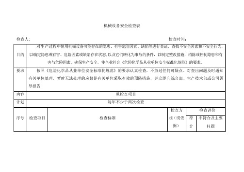
9.发电机绝缘部件无裂纹和起泡现象
10.仪表及附件齐全、运行良好;
11.泠却水管无渗漏、无水垢
12.发电机与电缆之间的连锁保护装置有效;
13.内燃机的排烟管口,安装阻火器;
14.气温在0℃以下时冷却水箱内宜添加防冻液;使用冷却水的发电机组在停机后必须及时放空冷却水箱,防止冻裂发电机组;
机械设备安全检查表
检查人: 检查时间:
目的
对生产过程中使用机械设备可能存在的隐患、有害危险因素、缺陷等进行查证,查找不安全因素和不安全行为,以确定隐患或有害、危险因素或缺陷存在状态,以及它们转化为事故的条件,以制定整改措施,消除或控制隐患和有害与危险因素,确保生产安全,使企业符合《危险化学品从业单位安全标准化规范》的要求。
5.泵体及管线内无噼啪作响的声音;
6.泵出口流量无大幅度变化
7.装卸泵未发生汽蚀现象;
8.装卸泵未出现抱轴现象;
9.装卸泵润滑良好;无异常响动,润滑油无“跑、冒、滴、漏"现象;润滑油足量;
4
柴油发电机
1.发电机基础、机座坚固完整,地脚螺丝满扣、紧固,柴油发电机组各部位应正常,各附件的联接紧固牢靠,各传动件及操纵系统应灵活
9.焊接二次线长度小于或等于30m,接头不许超过3个
10.电缆线外皮完整、柔软;
11.要有防弧光辐射、通风防尘措施。
查看现场
12.操作人员持证上岗。
13.必须办理动火证;
3
防爆电动机装卸泵,生产泵
1.泵及辅助系统无异常震动;
2.轴承温度无异常升高;
3.装卸泵无泄漏现象;
4.电动机运行正常且防爆符合要求;
4.焊钳绝缘可靠,隔热层完好,焊钳夹紧力好,手柄有良好的绝缘层,电焊钳与电缆的连接应简单牢靠,接触良好,不准将过热的电焊钳浸在水中冷却后使用
ASME质控手册样表

规范补遗核实表CODE EDITION /ADDENDA REVIEW CHECK LIST材料验收合格章MATERIAL ACCEPTANCE STAMP材料到货检验记录(钢板)(A)RECEIVING EXAMINATION RECORD (FOR PLATE) (A)合格标签ACCEPT LABEL绿色GREEN材料发放卡MATERIAL ISSUANCE CARD材料标记核对单MATERIAL CHECK LIST (A)使用库存材料征询单INQUIRY ABOUT USING STOCK MATERIAL验收单总表号COL PACKAGE NO.验收单CHECK OFF LIST PACKAGE (REVISION STATUS)铭牌NAMEPLATENotes:1.When the vessel not registered, NB stamp block shall not appear on thenameplate.2.The required markings on a nameplate shall be in characters not less than 5/32in (4 mm) high. The dimension of nameplate shall be as specified in thedrawing.3.The maximum allowable external working pressure (MAEWP) is required onlywhen specified as a design condition.不一致品处理通知单NON-CONFORMITY REPORT停止标签HOLD LABEL黄色YELLOW报废标签REJECT LABEL红色RED已有资格焊工表QUALIFIED WELDER’S LIST焊工资格验证表WELDER’S QUALIFICATION CONTINUITY RECORDMa: Machine; M: Manual; A: Automatic; S: Semi. Automatic.焊接材料发放单WELDING MATERIAL ISSUANCE CARD焊缝识别卡J OINT IDENTIFICATION CARD (JIC)(COVER SHEET)焊缝识别卡JOINT IDENTIFICATION CARD (JIC)SUNPOWER已有资格人员表LIST OF CERTIFIED NDE EXAMINERS编制:日期:PREPARED BY:Date:批准:日期:APPROVED BY:Date:热处理记录HEAT TREATMENT RECORD计量检定标签CALIBRATION LABELCertificate Expiration DateCalibrater专用标签SPECIAL LABEL计量器具管理台帐⑴⑴Equipment Master List ⑸Calibrate Cert. No. ⑼Measuring Range ⒀Status ⒄Calibrated Date⑵DOC. No ⑹Manufacture No. ⑽Accuracy ⒁Control Class ⒅Expiration Date⑶No. ⑺Equipment Name ⑾Manufacturer ⒂Calibrated Cycle ⒆Calibrator⑷Equipment ID. No. ⑻Type No. ⑿Issued to ⒃Calibrated By受控本手册发放表QC MANUAL HOLDER’S LIST指定人DESIGNATED BYQCD MANAGER文件发放表DOCUMENT LIST工号WORK NO.:编制日期批准日期份数PREPARED BY: DATE: APPROVED BY: DATE: *C: Nos. of Copy材料请购单MATERIAL REQUISITIONPage of采购单PURCHASE ORDER供方Vendor:材料标记核对单MATERIAL CHECK LIST ( B )验收单SUNPOWER产品焊接记录表PRODUCTION WELDING RECORD热处理工艺卡HEAT TREATMENT INSTRUCTION材料到货检验记录RECEIVING EXAMINATION RECORD (B)。
ASME质量体系审核检查表-中英文

(b)检验员应有材料测试报告或证明、检验报告、测试记录和其它制造记录;
(c)应为中转标识建立措施确保可追溯性;
如果编码标识系统被使用,应建立文件并被检验员接受;
(d)建立措施确保检验员接近检验点时并通知;
(e)修理材料时AI应在场;(不适用H、V、HV、UD、UV和UV3)
(l)(仅适用于RP)
(1)树脂混合程序需要被规定;
(2)建立措施包括存储、发货、处理和配置树脂、催化剂、装填物和颜料;
(m)(仅适用于RP)程序应包括:
(1)装配和调试压力容器和部件;
(2)连接部件;
质控
工程师
项目
质量要素
主谈人
不合格品的处置
建立程序纠正不合格品;需AI参与,该程序也须经AI同意;本程序提供给:
(c)履行质量控制职责的人员要有足够的和明确规定的责任、权利和组织去确认质量控制问题,并首先提出,推荐或提供问题解决方案;
总经理
(人资)
组织
要有一张能够反映真实的组织结构的组织机构图,它要显示出管理层与工程师、采购、制造、生产、现场装配、现场构造、检验和质量控制人口贩关系;
注:组织机构图的制作目的是确定各种不同职责的组织成员并把这些人员联系起来;这项规定并不是要侵占证书持有建立和适时改变其其认为适合规范要求的组织形式的权利;
AUTHORITY AND RESPONSIBILITY
(a) The authority and responsibility for QC by management is documented.
Note: In practice, a Statement of Policy and Authority must be signed by a senior company official responsible for Code activities (e.g., President, Vice President, Plant Manager, etc.).
仪器安全检查表(专业性)
仪器安全检查表(专业性)仪器安全检查表1. 仪器信息- 仪器名称:- 仪器型号:- 制造商:- 购买日期:- 上次维护日期:2. 安全检查项请按照以下检查项逐一检查仪器的安全状况,并记录任何发现的问题或异常情况。
2.1 电源和电线- [ ] 电源线是否完好无损?- [ ] 电源插头是否松动或损坏?- [ ] 是否有裸露的电线或电缆?- [ ] 是否有电线或电缆被压在重物下?- [ ] 是否有电源线缠绕在仪器周围或脚下?2.2 开关和控制面板- [ ] 开关是否灵活易用?- [ ] 控制面板的按钮是否松动或损坏?- [ ] 是否有任何异常的声音或异味?2.3 仪器外观- [ ] 仪器外观是否完好无损?- [ ] 是否有任何异常的变形或裂纹?- [ ] 是否有液体或杂物附着在仪器表面?2.4 安全设备- [ ] 仪器是否配备了必要的安全设备?- [ ] 安全设备是否正常工作?- [ ] 是否存在任何遗漏或损坏的安全设备?2.5 使用说明和警示标签- [ ] 使用说明书是否清晰易懂?- [ ] 是否存在不容易理解的部分?- [ ] 是否有警示标签缺失或损坏?3. 安全问题记录请在下方记录任何发现的安全问题或异常情况,并及时采取必要的维护或修复措施。
---备注请在此处添加任何其他信息或备注。
---以上是仪器安全检查表,鉴于您提供的信息有限,建议在使用仪器之前仔细阅读使用说明和寻求专业人士的意见。
如有任何安全或操作方面的疑问,请立即与相关负责人联系,确保安全使用仪器。
如有其他问题或需要进一步协助,请随时与我联系。
ASME 取证(专业部分)

ASME 取证试题(专业部分)一、设计方面(压力容器UG、UW 和UCS)1.常规压力容器强度计算书应该包含哪些基本内容?筒体的强度计算应该考虑哪些要求?椭圆封头的强度计算应该考虑哪些要求?2.如何确定压力容器设计过程中引用标准的版本?如何考虑单位制统一的问题,规范怎么要求的?3.如何考虑规范中没有提到的计算,比如支座计算?4.压力容器的腐蚀裕量是由设计工程师指定吗?设计工程师如何审核用户设计规范?5.对于锅炉和压力容器,静压头是否都一定要考虑?6.压缩空气储罐的受压件最小要求壁厚是多少?7.哪些材料可以允许用于制造压力容器的受压件?允许的螺栓,螺母材料是哪些?压力容器非受压件是否需要是ASME 材料?8.压力容器人孔的设计方面的有什么要求?容器排污孔的位置有什么要求?计算书中的所有的尺寸是腐蚀前还是腐蚀后?9.判定压力容器是否需要焊后热处理的因素有哪些?公称厚度的定义?10.什么情况下压力容器必须拍片?如果规范不强制拍片,那么由谁决定拍片的比例?11.如果容器接管开孔在焊缝上,接管满足UG-36(c)(3)的要求不需要计算开孔补强,对这样的开孔处的焊缝有没有RT 的要求?12.判定压力容器是否需要冲击试验的因素有哪些?是否只是受压件需要考虑低温冲击?考虑低温冲击时,控制厚度的定义?设计工程师请熟悉附录JJ!13.对于压力容器,免除开孔补强计算的开孔应满足什么条件?14.是不是所有尺寸的补强圈都可以完整的考虑为补强的范围内,即补强的范围?15.压力容器接管厚度的计算需满足那些要求?16. 针对容器,考虑冲击试验时,SA-105,SA-516 Gr70 正火,SA-106B 分别属于哪一种曲线?17. 一台容器打了RT-3 标记,封头和筒体焊接用Type 1 的接头形式,封头计算时的焊接接头系数为多少?18. 一台容器封头为无缝,筒体纵缝RT抽拍,封头与筒体的环缝抽拍并同时满足UW-11(a)5(b)的要求,计算封头壁厚时的焊接接头系数为多少?筒体接头系数为多少?容器打RT-1,RT-2,RT-3 还是RT-4?19. SA 106B 和A106B 什么区别?能等同的材料吗?20.针对容器,封头成型后如何判定是否需要成型后热处理?如何判定是否需要带成型试板?21.如何判定焊缝强度是否需要计算?22.压力容器的水压试验压力值如何确定?水压试验温度是指介质温度还是金属温度?具体的温度值有何要求?23.压力容器铭牌的要求有哪些?24.如果容器的铭牌直接装在设备上,铭牌可以装在与设备相连的支架上,这种情况下,铭牌与容器的距离有无具体的要求?二、材料方面1. SA-516 Gr70 的质保书有哪些要求?SA-106 GrB 质保书有哪些要求?2. SA-516 Gr 70 ,20mm 厚,允许的尺寸变差是多少?板材原始标记的要求是哪些?3.B16.5 法兰,材料SA-105 要求的标记有哪些?质保书要求哪些内容?是否需要作入厂验收?4.SA-106B 要求的标记有哪些?要求哪些性能试验,允许的尺寸偏差为多少?5. N, QT, Ceq 是什么意思?6.ASME 材料如何进行验收?是否需要复验?是否一定需要质保书?哪些材料需要质保书?ASME 焊材如何进行验收?是否一定需要质保书?第I 卷和VIII-1 卷对材料质保书方面的要求是否一样?7.材料入厂验收的基本流程是怎样的?每一过程需要哪些文件?验收合格的材料由谁指定材料追踪号?如何指定?8.谁负责登记材料追踪号的台帐?9.如果材料验收不合格,如何处理?如果需要对母材进行补焊,应该如何操作?10.如果外购的无缝封头,应该如何进行验收?采取什么样的方式追踪其材料追踪号?三、焊接方面1.手工焊,自动焊,机器焊的定义?2. 哪些焊接方法能用于焊接VIII-1 卷的容器?3. WPS,PQR 都应该分别包含哪些变素?4. WPS 里的非重要变素发生变化时,如何处理?5.P-No.,F-No. A-No.分别含义?6. WPS 中的焊材不属于任何一个A-No.,如何处理?7.焊工考试试样的试验有哪些项目?哪些焊接方法可以用RT替代力学性能试验?RT评定合格的依据是第五卷吗?这种情况下对焊缝长度有要求吗?8.PQR 机械性能包含哪些试验项目?合格依据是什么?可以用RT代替力学性能试验吗?9.管接头与筒体的焊接接头采用骑座式,管接头尺寸为1'', 那么焊这条焊缝的焊工应该如何进行考试?如果接头形式为插入式呢?焊工应该具有什么位置的资格?10.焊接非受压件与受压件的焊工是否需要评定合格的焊工?是否需要评定合格的WPS, 允许进行焊接的最低温度是多少?11.非受压件是否一定需要是ASME 材料?非受压件与受压件的焊缝要求在哪一章节?12. 如果WPS 评定P-NO. 1 材料并合格,那么这个WPS 能覆盖哪些材料?13. 如果焊工考试有F-NO.3 带垫板,那么这个焊工焊接哪些F-No.?14. 如何维持焊工的资格?15. 焊接工艺评定试板材料为SA-516 Gr 70,厚度为9mm,那么弯曲半径为多少?如果试样厚度为40mm,那么做拉伸实验时如何处理?16.低氢焊条的烘培温度,烘培时间依据是什么?能够回收几次?如何标识回收焊条?如何控制回收的焊条?四、检验方面1.检验员如何进行装配检查?点焊检查?焊缝检查?如果是RT抽拍,由谁指定抽拍的位置?2.错边量的要求在哪一章节?焊缝余高要求在哪一章节?3.检验员在焊接前应该检查什么?焊接中检查什么?焊接后检查什么?4.如果在检验过程中出现NCR, 应该采取怎样的步骤?5.检验接管与筒体的角焊缝尺寸时,图纸规定的尺寸是是仅值沿筒体纵向的焊脚尺寸还是针对整个焊缝焊脚?6.热处理工程师在准备焊后热处理工艺卡时,保温温度,升温速度,降温速度,如炉温度,出炉温度,保温时间依据在那一章节?7.热处理分包前和分包后如何控制?8.容器在水压试验之后,打U 钢印之前,在受压件上焊接非受压件,是否需要重新进行水压试验?9. MDR 是什么?如何选用相应格式的MDR? 请质检部经理负责熟悉并填写MDR。
- 1、下载文档前请自行甄别文档内容的完整性,平台不提供额外的编辑、内容补充、找答案等附加服务。
- 2、"仅部分预览"的文档,不可在线预览部分如存在完整性等问题,可反馈申请退款(可完整预览的文档不适用该条件!)。
- 3、如文档侵犯您的权益,请联系客服反馈,我们会尽快为您处理(人工客服工作时间:9:00-18:30)。
容器组装检查记录
产品名称产品编号图号
材料牌号规格备注检查项目图样要求检查结果检查结论备注
管口方位检查记录
壳 体 内 径 1300 壳体圆度允差 e ≤1%DN 坡口角度
30°±2.5° A类焊缝错边量
≤1/4t B类焊缝错边量
≤1/4t
焊缝余高
B 、
C 类 ≤4
其他 ≤2.4
壳体表面机械损伤 合格 管 口 方 位 图样 裙(支)座方位 图样 裙(支)座螺栓孔距 ±2 设备主体总长 L =2817 法兰螺孔位置 跨中或对中 法兰密封面质量
无划痕
结论:
检验员: 年 月
日
产品名称
产品编号 图 号
材料牌号
规 格
备 注
接管方位简图:
90°
180°
270°
管
口代号件
号
接管方位及
位置尺寸
操作人接管高度法兰面倾斜度操作人标准值实测值标准值实测值允差实测
结论:
检验员:年月日。
