YSPA PUBL-7266ZH(0315)
726 Users Manual Supplement说明书

Manual Supplement© 2007-2015 Fluke Corporation. All rights reserved.Manual Title: 726 Users Supplement Issue: 7 Print Date: September 2005 Issue Date: 7/15 Revision/Date: Page Count: 8This supplement contains information necessary to ensure the accuracy of the above manual. This manual is distributed as an electronic manual on the following CD-ROM:CD Title: 725/726 CD Rev. & Date: 4, 9/2005 CD PN: 1549615726 Users Manual Supplement7/15 1Change #1On page 2, replace the Pulse row with the following:Pulse1-100,000Frequency Max 15 kHz1-10,000Frequency Range 2 CPM to 15 kHzOn page 12, Table 4, replace the Description for Number with the following:Cycles through:Slow repeating 0 % - 100 % - 0 % rampConfigurable repeating 0 % - 100 % - 0% rampConfigurable repeating 0 % - 100 % - 0 % ramp in 25 % steps Used for the pulse train and totalizer functions.On page 13, replace Figure 4 with the following:Manual Supplement 726 Users2 7/15Figure 4. Elements of a Typical Display726 Users Manual Supplement7/15 3On page 14, under Configuration Menus , add the following under the last bullet: • Step time • Ramp timeOn page 15, under Shut Down Mode , replace numbered steps with the following: 1. Press until SHUT DOWN appears on the display. 2. Use and to increase or decrease the time. 3. Use and to turn on and off. 4. Press to save the setting.On page 16, under Hart Resistor ON/OFF , replace step 2 with the following: 2. Use or and to toggle ON and OFF. Add the following below the Note :Step TimeStep Time sets the ramp step time from 1 sec to 99 sec. 1. Press until STEP TIME appears on the display. 2. Use and to set the step time. 3. Press to save the setting.Manual Supplement 726 Users4 7/15Ramp TimeRamp Time sets the ramp time from 5 sec to 99 sec. 1. Press until RAMP TIME appears on the display. 2. Use and to set the ramp time. 3. Press to save the setting. On page 25, Table 6, add the following:Cu10 10 Ω Copper0.0042 Ω/°C-100 to 250On page 42, under Auto Ramping the Output , replace the 2nd and 3rd bullets with the following:• 0 % - 100 % - 0 % configurable time smooth ramp. Set ramp time using configurationmenu. • 0 % - 100 % - 0 % Stair-step ramp in 25 % steps, pausing at each step. Set ramptime using configuration menu. Steps are listed in Table 7. On page 60, under Frequency Measurement , add the following to the bottom of the table:Sensitivity: 1 V peak to peak minimum Waveform: Squarewave726 Users Manual Supplement7/15 5On page 62, change the Range entries for “Thermocouple in mV read” and “Thermocouple in mV source”:From:-10 °C to 75 °C To: -10 mV to 75 mVOn page 63, under the RTD Accuacy (Read and Source) (ITRS-90) table, replace the CU10 rowwith the following:Cu10 -100.0 250.00 1.8On page 64, under Pulse Read and Pulse Source , replace the Frequency entry with the following:2 CPM to 15 kHzManual Supplement 726 Users6 7/15Change #2, 57003On page 5, add the following under Caution:Static SensitiveThe 726 MEASURE/SOURCE terminals are ESD (electro-static discharge) sensitive to levels above ± 4 kV. The Calibrator can experience temporary loss of measurement or source functionality, which may require operator intervention to restore product function, or even cause permanent damage. In general, a disruptive ESD event will only occur during connection of the test leads to the circuits being measured or if the operator is carrying a large static charge and touches the Calibrator terminals. The most common cause of ESD is the user carrying the Calibrator across a carpet, or other similar triboelectric activity, before they connection to the circuit being measured.On page 59, in the notes under DC mA Measurement and Source , add:When in a 3 V/m radiated EM field ≤ 300 MHz, floor counts are increased to 30 μA in mA Read.On page 60, in the notes under Ohms Measurement add:When in a 3 V/m radiated EM field ≤ 300 MHz, floor counts are increased to 2.5 Ω in 400 Ω range.726 Users Manual Supplement7/15 7On page 61, in the notes under Temperature, Thermocouples add:When in a 3 V/m radiated EM field ≤ 300 MHz, add 2 % of range for all TC types.Change #3On page 54, Table 8:Change:8Test lead, red Test lead, black688051 688066 1 1To:8Fluke-7XX Test Lead Set33973081Change #4, 67391, 171, 512On page 7, under Table 2, add:SymbolMeaningConsult user documentation.Conforms to relevant Australian EMC standards.Conforms to relevant South Korean EMC Standards.Manual Supplement 726 Users On page 65, under General Specifications, replace the Safety section and add:Safety IEC 61010-1: Pollution Degree 2Electromagnetic Compatibility(EMC)International IEC 61326-1: Portable Electromagnetic EnvironmentCISPR 11:Group 1, Class AGroup 1: Equipment has intentionally generated and/or uses conductively-coupled radiofrequency energy that is necessary for the internal function of the equipment itself.Class A: Equipment is suitable for use in all establishments other than domestic andthose directly connected to a low-voltage power supply network that supplies buildingsused for domestic purposes. There may be potential difficulties in ensuringelectromagnetic compatibility in other environments due to conducted and radiateddisturbances.Emissions that exceed the levels required by CISPR 11 can occur when the equipmentis connected to a test object.Korea (KCC) Class A Equipment (Industrial Broadcasting & Communication Equipment)Class A: Equipment meets requirements for industrial electromagnetic wave equipmentand the seller or user should take notice of it. This equipment is intended for use inbusiness environments and not to be used in homes.USA (FCC) 47 CFR 15 subpart B. This product is considered an exempt device per clause 15.103.8 7/15。
维萨拉工业测量产品手册说明书

维萨拉工业测量产品手册湿度 | 温度 | 露点 | 二氧化碳 | 沼气 | 油中水分 | 连续监测系统 |溶解气体分析系统 | 过氧化氢 | 压力 | 气象 | 服务支持观测让世界更美好维萨拉的工业测量业务领域产品能够帮助客户了解工艺过程。
我们的产品为客户提供准确可靠的测量数据,帮助客户做出优化工业过程的决策,从而提高过程效率、产品质量、生产力和产量,同时减少能源消耗、浪费和排放。
我们的监测系统还能帮助客户在受监管的环境中运营,以履行监管合规性。
维萨拉工业测量服务于多种类型的运营环境,从半导体工厂和高层建筑,到发电厂和生命科学实验室,对环境条件的可靠监测是实现成功运营的先决条件。
维萨拉的测量产品和系统广泛应用于监测温度、湿度、露点、气压、二氧化碳、汽化过氧化氢、甲烷、油中水、变压器油中溶解气体和液体浓度等参数。
我们的生命周期服务可在测量仪表的整个使用寿命内提供维护。
作为值得信赖的合作伙伴,我们通过在产品和系统生命周期中保证准确的测量数据来支持客户做出可持续的决策。
本产品目录对我们的产品进行整体的介绍,以帮助您选择适合您需求的产品。
如需更多信息,请通过以下方式联系我们:销售热线:400 810 0126电子邮箱:**********************公司网址:扫描二维码,关注维萨拉企业微信3目 录Indigo系列变送器Indigo200系列数据处理单元 (7)Indigo300数据处理单元 (9)Indigo510数据处理单元 (12)Indigo520数据处理单元 (15)用于抽检和校准的手持设备Indigo80手持式显示表头 (18)HMP80系列手持式湿度和温度探头 (21)DMP80系列手持式露点和温度探头 (23)HM70手持式湿度和温度仪 (26)HUMICAP® 手持式湿度温度仪表HM40系列 (29)DM70手持式露点仪 (33)MM70适用于现场检测的手持式油中微量水分和温度测试仪 (36)湿度和温度用于测量相对湿度的维萨拉HUMICAP® 传感器 (38)如何为高湿度应用选择合适的湿度仪表 (40)Insight PC机软件 (44)HMP1墙面式温湿度探头 (46)HMP3一般用途湿度和温度探头 (48)HMP4相对湿度和温度探头 (51)HMP5相对湿度和温度探头 (54)HMP7相对湿度和温度探头 (57)HMP8相对湿度和温度探头 (60)HMP9紧凑型湿度和温度探头 (63)TMP1温度探头 (66)适用于苛刻环境中湿度测量的HMT330系列温湿度变送器 (68)HMT370EX系列本安型温湿度变送器 (78)HMT310温湿度变送器 (84)HUMICAP® 温湿度变送器HMT120和HMT130 (87)适用于高性能暖通空调应用的HMW90系列湿度与温度变送器 (90)HMD60系列湿度和温度变送器 (92)HMD110/112和HMW110/112湿度和温度变送器 (96)适用于楼宇自动化高精度室外测量的HMS110系列温湿度变送器 (99)HMDW80系列温湿度变送器 (101)适用于楼宇自动化应用室外测量的HMS80系列温湿度变送器 (105)HMM100湿度模块 (107)适用于OEM应用的HMM105数字湿度模块 (109)HMM170温湿度模块 (111)INTERCAP® 温湿度探头HMP60 (113)4INTERCAP® 温湿度探头HMP63 (115)HUMICAP® 温湿度探头HMP110 (117)HUMICAP® 温湿度探头HMP113 (120)SHM40结构湿度测量套件 (122)HMK15湿度校准仪 (125)DTR500太阳辐射和雨水防护罩 (127)HMT330MIK气象安装套件 (129)适用于动力汽轮机进气测量的HMT300TMK汽轮机安装组件 (131)露点Vaisala DRYCAP® 传感器用于测量干燥过程中的湿度 (133)DMP5露点和温度探头 (135)DMP6露点探头 (138)DMP7露点和温度探头 (140)DMP8露点和温度探头 (142)DMT340系列露点和温度变送器 (145)适用于高温应用的DMT345和DMT346露点变送器 (151)DMT152露点变送器 (155)DMT143露点变送器 (157)DMT143L露点变送器 (160)用于冷冻干燥机的DMT132露点变送器 (162)DM70用DSS70A便携式采样系统和采样室 (164)DPT146露点和气压变送器 (166)DPT145多参数变送器 (168)二氧化碳适用于苛刻环境的维萨拉CARBOCAP® 测量传感器 (171)GMP343二氧化碳探头 (173)适用于CO2恒温箱的GMP231二氧化碳探头 (176)GMP251二氧化碳探头 (178)GMP252二氧化碳探头 (181)GM70手持式二氧化碳测试仪 (184)适用于苛刻通风要求应用的GMW90系列二氧化碳及温湿度变送器 (187)适用于智能控制通风系统 (DCV) 的GMW80系列二氧化碳、湿度和温度一体变送器 (190)按需控制通风系统中的GMD20系列二氧化碳变送器 (193)GMD110管道安装式二氧化碳变送器 (195)沼气MGP261多气体探头 (197)MGP262多气体探头 (199)油中水用于测量油中微水的维萨拉HUMICAP® 传感器 (201)MMP8油中水分探头 (203)MMT330系列油中微量水分与温度变送器 (205)5MMT310系列油中微量水分与温度变送器 (209)MMT162油中微量水分和温度变送器 (211)连续监测系统维萨拉viewLinc企业版服务器版本5.1 (213)AP10 VaiNet无线接入点 (215)用于连续监测系统的RFL100无线数据记录仪 (218)HMP115温湿度探头 (223)TMP115宽范围温度探头 (225)维萨拉温度与相对湿度数据记录仪系列DL2000 (227)维萨拉通用输入数据记录仪系列DL4000 (229)维萨拉多应用温度数据记录仪DL1016/1416 (231)维萨拉热电偶数据记录仪系列DL1700 (233)维萨拉中端温度、湿度及触点通道数据记录仪 (235)维萨拉vNet以太网供电数据记录仪接口 (238)溶解气体分析OPT100 Optimus™ 溶解气体分析(DGA)监测系统 (240)MHT410变压器油中微量水分、氢气和温度分析仪 (244)过氧化氢用于测量汽化过氧化氢、相对饱和度和相对湿度的维萨拉PEROXCAP® 传感器 (246)用于过氧化氢、湿度和温度测量的HPP270系列探头 (249)压力用于测量压力的维萨拉BAROCAP® 传感器 (253)PTU300气压、湿度和温度一体变送器 (255)适用于专业气象、航空与工业用户的PTB330数字式气压计 (260)气压传递标准PTB330TS (262)PTB210数字气压计 (265)PTB110气压计 (267)将风引起误差降低的SPH10/20静压头 (269)气象Vaisala用于工业应用测量的风和气象传感器技术 (271)风测量装置WA15 (273)WINDCAP® 超声波风传感器WMT700系列 (276)气象变送器WXT530系列 (278)服务支持面向仪表全生命周期服务 (280)67功能•数据处理单元 USB-C 端口支持使用通用 USB 电缆连接到维萨拉Insight PC 软件•数字和图形彩色显示屏(针对模拟型号提供可选的不带显示屏的款式)•IP65 外壳•24 V AC/DC 电源输入•Indigo201:3 个模拟输出(mA 或 V)•Indigo202:RS-485,带有Modbus ® RTU•2 个可配置的继电器维萨拉 Indigo200 系列数据处理单元是一种主机设备,它显示来自维萨拉 Indigo 兼容探头的测量值,同时也可通过模拟信号、Modbus RTU 通信或继电器将这些测量值传输到自动化系统。
Tron 产品说明书

COMPASS01-0226-03GYROTRAC SYSTEM FOC-WO 1.00SET21F COMPASS01-0226-03GYROTRAC SYSTEM FOC-WO 1.00SET PHLIA WIND DATA SYSTEM05106RM YOUNG WIND MONITOR - MA P221-1334 1.00SET XXX WIND DATA SYSTEM05108RM YOUNG WIND MONITOR HD P222-14537.00SET19F WIND DATA SYSTEM06206-27RM YOUNG MARINE WIND TRACKER -110/220VAC P222-1453 3.00SET19F WIND DATA SYSTEM06206-27RM YOUNG MARINE WIND TRACKER -110/220VAC SHAC31 P221-0710 1.00SET SHAC 101700TRON TR30 AIR EMERGENCY VHF AM RADIO P222-0087 1.00SET19F103170EPRIB - TRON 60AIS WITH FLOAT FREE BRACKET P223-0001 4.00SET19F103170EPRIB - TRON 60AIS WITH FLOAT FREE BRACKET P222-0670 1.00SET SHAT1305118DM100 VDR G2P221-1683*3 1.00SET BOND710S-00607SAFESEA S100 SART WITH MOUNTING POLE P222-00748.00SET PHLIA EPIRB8305083050 TRON 40S MKII (WITHOUT BRACKET)FOC-P218-2570 1.00SET19F EPIRB83310TRON 60S EPIRB W/FF BRACKET P222-0776 1.00SET19F EPIRB83310TRON 60S EPIRB W/FF BRACKET P222-0331 1.00SET GZLF EPIRB83310TRON 60S EPIRB W/FF BRACKET P222-0776 2.00SET SHAT EPIRB83310TRON 60S EPIRB W/FF BRACKET P222-0776 1.00SET XXX19 83330TRON 60GPS EPIRB WITH FLOAT FREE BRACKET P222-07767.00SET19F83330TRON 60GPS EPIRB WITH FLOAT FREE BRACKET P222-0776 1.00SET SHAT VHF / UHF87950P221-0958 1.00SET19F VHF / UHF87950P222-067039.00SET19F VHF / UHF87950SHAC26 P221-0014 1.00SET SHAC VHF / UHF87950P221-0631 1.00SET SHAT A45P & E ANEMOMETER P221-1367 1.00SET PANYUAC3161200407222A-00500 SAILOR 7222 VHF DSC Class A P222-0139 3.00SET19FAC3496400C1-70-A00S INTELLIAN C700 CERTUS TERMINAL P221-1117 1.00SET PHLIA AUTOPILOT ALPHAPILOT-IU*AUTOPILOT (CONTACT O/P) CONNECTION TERMINAL (LOCAL MADE)FOC 4.00SET19F GYROCOMPASS CMZ-900B2GYRO COMPASS P222-1289 1.00SET19F ECHO SOUNDER CVS-126KODEN ECHO SOUNDER (600W, 200KHZ, DC24V OPERATION)P221-0821 1.00SET PHLIA ECHO SOUNDER CVS-126KODEN ECHO SOUNDER (600W, 200KHZ, DC24V OPERATION)P222-0118 3.00SET PHLIA ECHO SOUNDER CVS-126KODEN ECHO SOUNDER (600W, 200KHZ, DC24V OPERATION)P222-090520.00SET PHLIA ECHO SOUNDER CVS-128KODEN ECHO SOUNDER(8.4-INCH COLOR LCD)P222-0905 2.00SET19F ECHO SOUNDER CVS-128KODEN ECHO SOUNDER(8.4-INCH COLOR LCD)P222-0905 1.00SET PHLIA ECHO SOUNDER CVS-FX2KODEN DIGITAL BROADBAND ECHO SOUNDER C/W TRANSDUCER & STANDARD ACCESSORIES FOC-WO-P215-1160 1.00SET PHLIA NAVTEX DPU-414-50B-E PRINTER P222-0996 1.00SET DL NAVTEX DPU-414-50B-E PRINTER SHAC21 P219-0539 1.00SET DL NAVTEX DPU-414-50B-E PRINTER SHAC21 P219-0538 1.00SET FZ NAVTEX DPU-414-50B-E PRINTER P219-0538 1.00SET PANYU NAVTEX DPU-414-50B-E PRINTER CONSIGNMENT 1.00SET PHLIA NAVTEX DPU-414-50B-E PRINTER P221-0068 2.00SET PHLIA NAVTEX DPU-414-50B-E PRINTER P222-1020 1.00SET SHAI DT885FF ENTEL FIRE FIGHTER RADIO (UHF), ATEX IIB P221-014712.00SET19FDT885FF ENTEL FIRE FIGHTER RADIO (UHF), ATEX IIB ENT-P221-0011 6.00SET SHACDT985FF ENTEL FIRE FIGHTER RADIO (UHF), ATEX IIC P221-14248.00SET19FDT985FF ENTEL FIRE FIGHTER RADIO (UHF), ATEX IIC P222-118720.00SET19F VHF / UHF DX482ENTEL UHF P218-1451 1.00SET19F VHF / UHF DX482ENTEL UHF P218-1451 2.00SET SHAT VHF / UHF DX482ENTEL UHF P218-1451*2 3.00SET SHAT DX585M-IS UL913 INTRINSICALLY SAFE UFH (NON EU)P222-11417.00SET19F FAX / WEATHER FAX FAX-236BROTHER FAX MACHINE ( AC 220V )FOC-WO-P211-0201 1.00SET21F FAX / WEATHER FAX FAX-236BROTHER FAX MACHINE ( AC 220V )FOC-WO-P211-0201 1.00SET PHLIA VHF / UHF FM8800S*VHF (SECOND HAND)FOC-WO-P215-0960 1.00SET SGP GC80SIMRAD GYRO COMPASS P221-1563 1.00SET PHLIA GPS / DGPS GP-170GPS P222-0649 1.00SET PHLIA PUBLIC ADDRESSER HPA-7300PUBLIC ADDRESSER/ TALK-BACK SYSTEM CONSIGNMENT-PGH270210.70SET PANYU PUBLIC ADDRESSER HPA-9200PUBLIC ADDRESSER/ TALK BACK SYSTEM CONSIGNMENT-PGH27021 1.00SET PANYU VHF / UHF HT544ENTEL HANDHELD VHF (I.S. TYPE) WITH LCD DISPLAY ENT-P220-0003 2.00SET SHAC VHF / UHF HT583(RED-BEZEL)ENTEL I.S. UHF P221-0147 4.00SET19F VHF / UHF HT583(RED-BEZEL)ENTEL I.S. UHF P221-106117.00SET19F VHF / UHF HT583(RED-BEZEL)ENTEL I.S. UHF P221-1061 3.00SET SHAT VHF / UHF HT649-GMDSS/P2ENTEL 2-WAY VHF P222-163411.00SET19F VHF / UHF HT649-GMDSS/P2ENTEL 2-WAY VHF P222-1634 6.00SET SHAT VHF / UHF HT782UHF P221-1424 1.00SET19F VHF / UHF HT782UHF ENT-P220-0003 2.00SET SHAC VHF / UHF HT883ENTEL I.S. UHF P218-12858.00SET19F VHF / UHF HT883ENTEL I.S. UHF ENT-P220-0003 1.00SET SHAC VHF / UHF HT883(RED-BEZEL)ENTEL I.S. UHF P218-1201 6.00SET13F VHF / UHF HT883(RED-BEZEL)ENTEL I.S. UHF P218-0235 4.00SET19F VHF / UHF HT883(RED-BEZEL)ENTEL I.S. UHF P218-0699 4.00SET19F VHF / UHF HT883(RED-BEZEL)ENTEL I.S. UHF ENT-P220-0003 6.00SET SHAC VHF / UHF HT883(RED-BEZEL)ENTEL I.S. UHF P218-0235 1.00SET SHATVHF / UHF HT982ENTEL I.S. UHF P220-0104 4.00SET19F TELEPHONE HX-26AUTO EXCHANGE TELEPHONE SYSTEM CONSIGNMENT-PGH27021 1.00SET PANYU TELEPHONE HX-72AUTO-TELEPHONE SYSTEM CONSIGNMENT-PGH27021 1.00SET PANYU ECDIS JAN-2000JRC ECDIS FOC-WO-P216-0876 1.00SET PHLIA NECST JAN-470-4ANN NECST CONSIGNMENT 1.00SET PHLIA JAN-5203-26D ROUTE PLANNING SYSTEM, 26", DESK TOP TYPE P220-1749 2.00SET19F ECDIS JAN-701B*ECDIS (SECOND HAND)FOC-WO-P213-1313*10.90SET SHAT FAX / WEATHER FAX JAX-90*WEATHER FAX (SECOND HAND)FOC-WO-P213-1313 1.00SET SGP VDR SVDR JCY-1850*JRC SIMPLIFIED VOYAGE DATA RECORDER (SECOND HAND)FOC-WO-P215-0960 2.00SET SGP ECHO SOUNDER JFC-7050-W/OTD FISH FINDER (WITHOUT TRANSDUCER)FOC-WO-P215-1346 1.00SET PHLIA ECHO SOUNDER JFE-400-25ECHO SOUNDER WITH 200KHZ + 50KHZ DUAL TRANSDUCER (BB TYPE)P222-0682 1.00SET19F ECHO SOUNDER JFE-570S*NAVIGATION ECHO SOUNDER (SECOND HAND)FOC-WO-P213-1313 1.00SET SGP ECHO SOUNDER JFE-680JRC ECHO SOUNDER (WITHOUT TRANSDUCER)P221-0849 1.00SET19F AIS JHS-183AUTOMATIC IDENTIFICATION SYSTEM (AIS)P221-0837 1.00SET19F VHF / UHF JHS-32A*JRC VHF (SECOND HAND)FOC-WO-P213-1313 1.00SET PHLIA VHF / UHF JHS-32A*JRC VHF (SECOND HAND)FOC-WO-P215-0960*10.90SET SGP VHF / UHF JHS-32A*JRC VHF (SECOND HAND)FOC-WO-P215-0960 1.00SET SGP VHF / UHF JHS-32B*VHF/FM RADIOTELEPHONE (SECOND HAND)CONSIGNMENT 1.00SET PHLIA VHF / UHF JHS-7 2 WAY VHF RADIOTELEPHONE P219-1575*1 1.00SET19F GPS / DGPS JLR-21GPS COMPASS P222-0030 1.00SET19F GPS / DGPS JLR-4340GPS RECEIVER GPS-124 (WITH 15M CABLE)P218-0312*2 1.00SET19F GPS / DGPS JLR-7700MKII*GPS NAVIGATOR (SECOND HAND)FOC-WO-P215-0960 1.00SET SGP RADAR JMA-3336RADAR - X-BAND 6KW, 3.9FT OPEN SCANNER 10.4" DISPLAY P222-0318 1.00SET PHLIA JMA-3404JRC MARINE RADAR X-BAND, 4KW DOME SCANNER, 12/24VDC FOC-WO-P220-0946 3.00SET PHLIAJMA-3406JRC MARINE RADAR X-BAND, 6KW OPEN SCANNER, 12/24VDC P220-0946 1.00SET PHLIA RADAR JMR-9225-6XC X-BAND COLOR RADAR, 6FT ANTENNA OUTPUT POWER: 25KW STAND-ALONE TYPE P222-0744 1.00SET21F RADAR JMR-9225-6XC X-BAND COLOR RADAR, 6FT ANTENNA OUTPUT POWER: 25KW STAND-ALONE TYPE P222-0744 1.00SET BOND RADAR JMR-9230-SC S-BAND COLOR RADAR, 12FT ANTENNA OUTPUT POWER: 30KW STAND-ALONE TYPE P222-06990.90SET21F RADAR JMR-9230-SC S-BAND COLOR RADAR, 12FT ANTENNA OUTPUT POWER: 30KW STAND-ALONE TYPE P222-0170 1.00SET BOND RADAR JMR-9230-SC S-BAND COLOR RADAR, 12FT ANTENNA OUTPUT POWER: 30KW STAND-ALONE TYPE P222-06990.10SET GD MF/HF RADIO JSB-196GM*150W MHF/HF SSB RADIOTELEPHONE (SECOND HAND)FOC-P215-0960*1 1.00SET SGP INMARSAT JUE-85*INMARSAT-C MARINE MOBILE EARTH STATION (SECOND HAND)FOC-WO-P215-09600.90SET SGP INMARSAT JUE-95SA INMARSAT MINI-C MARINE MOBILE EARTH STATION P222-0682 1.00SET19F AIS KAT-100KODEN AIS TRANSCEIVER (DC OPERATION)P218-19660.50SET PHLIA KAT-330KODEN AIS TRANSCEIVER P222-0118 1.00SET19FKAT-330KODEN AIS TRANSCEIVER P222-0118 2.00SET PHLIAKAT-330KODEN AIS TRANSCEIVER P222-0905 6.00SET PHLIA ECHO SOUNDER KDS-6000BB KODEN DIGITAL BROADBAND SEARCH LIGHT SONAR P222-1707 2.00PC1PHLIA GPS / DGPS KGP-915KODEN GPS GLONASS P222-0905 3.00SET19F GPS / DGPS KGP-915KODEN GPS GLONASS P221-0821 2.00SET PHLIA GPS / DGPS KGP-915KODEN GPS GLONASS P222-0905 2.00SET PHLIA GPS / DGPS KGP-922GPS NAVIGATOR P222-0118 1.00SET19F GPS / DGPS KGP-922GPS NAVIGATOR P222-0118 1.00SET PHLIA GPS / DGPS KTN-70A PLOTTER P216-1791 1.00PC1PHJUN GPS / DGPS KTN-70A PLOTTER P219-172215.00PC1PHLIA RADAR MDC-204010.4-INCH COLOR LCD MARINE RADAR FOC-WO-P220-0861 2.00PC1PHLIA RADAR MDC-7912P-6X-BAND RADAR P222-1023 2.00SET19F RADAR MDC-7912P-6X-BAND RADAR P222-1023 2.00SET PHLIA RADAR MDC-941A KODEN 8.4 INCH COLOUR RADAR WITH 25" RADOME P222-0905 3.00SET19F RADAR MDC-941A KODEN 8.4 INCH COLOUR RADAR WITH 25" RADOME P220-0294*10.90SET PHLIA RADAR MDC-941A KODEN 8.4 INCH COLOUR RADAR WITH 25" RADOME P219-0298 1.00SET PHLIA RADAR MDC-941A KODEN 8.4 INCH COLOUR RADAR WITH 25" RADOME P222-0118 1.00SET PHLIA RADAR MDC-941A KODEN 8.4 INCH COLOUR RADAR WITH 25" RADOME P222-170712.00SET PHLIA RADAR MDC-941A KODEN 8.4 INCH COLOUR RADAR WITH 25" RADOME P222-090514.00SET PHLIA COMPASS MS-100MAGNETIC COMPASS A/D CONVERTOR FOC-WO-P210-0101 1.00SET21F COMPASS MS-100MAGNETIC COMPASS A/D CONVERTOR FOC-WO-P210-0261 2.00SET21F VHF / UHF NCM-1770-E CONTROLLER SHAC14 P219-1237*1 2.00SET SHAC NAVTEX NCR-333NAVTEX RECEIVER P222-1108 2.00SET19F NAVTEX NCR-333NAVTEX RECEIVER P219-1511*20.20SET PHLIA NAVTEX NCR-333NAVTEX RECEIVER P220-1728*10.80SET PHLIA NAVTEX NCR-333*NAVTEX RECEIVER (SECOND HAND)FOC-WO-P215-0960 2.00SET SGP NEB-2000NSR EPRIB WITH AIS P222-129515.00SET PHLIANEB-2000C NSR EPRIB P222-0737*10.90SET PHLIANEB-2000C NSR EPRIB P222-0737 1.00SET PHLIA VHF / UHF NKG-52*PRINTER (SECOND HAND)FOC-P215-0960 1.00PC1SGP NKG900A NKG-900 PRINTER P222-0682 1.00PC19FNKG900A NKG-900 PRINTER P222-04918.00PC19FNKG900A NKG-900 PRINTER P222-0144 1.00PC SHAT ECHO SOUNDER NKG-901PRINTER (FLUSH MOUNT)P222-0597 2.00PC119F ECHO SOUNDER NKG-91PRINTER (FLUSH MOUNT) REFER TO NKG-901FOC 1.00PC119FRADAR NRT-1000RADAR SART P222-0737 3.00SET PHLIA AIS NTE-183-E AIS TRANSPONDER SHAC30 P220-0605*1 1.00SET DL VHF / UHF NTE-770S-E VHF TRANSCEIVER SHAC13 P219-1237*1 2.00SET SHAC NVR-3000VHF P222-1386 2.00SET19F VDR SVDR NW-6000NETWAVE VDR P219-2455*5 1.00SET19F AUTOPILOT PR-8000*TOKIMEC AUTOPILOT (SECOND HAND)FOC-WO-P213-1313 1.00SET SGP AUTOPILOT PT900AWOCMZ900S AUTOPILOT (WITHOUT CMZ-900S)P218-1659*1 1.00SET21F AIS R4*AIS (SECOND HAND)FOC-P215-0960 2.00PC1SGP AUTOPILOT RFU ANSCHUTZ (FEEDBACK UNIT) WITH LINKAGE FOR NP60FOC 1.00SET19F AUTOPILOT RFU ANSCHUTZ (FEEDBACK UNIT) WITH LINKAGE FOR NP60FOC-P218-1009 1.00SET19F VHF / UHF RT5022*SAILOR RT5022 VHF DSC (2nd HAND)CONSIGNMENT 1.00SET SGP GYROCOMPASS TG-5000*TOKIMEC GYROCOMPASS (SECOND HAND)FOC-P215-0960 1.00SET SGP GYROCOMPASS TG-5000*TOKIMEC GYROCOMPASS (SECOND HAND)FOC-WO-P213-1313 1.00SET SGP VHF / UHF TLKR8PACKAGE C/W RECHARGABLE BATTERY, BATTERY CHARGER, EARBUD & USER MANUAL FOC-WO-P213-0004 2.00SET21F TRANSPONDER TRONSART20JOTRON RADAR TRANSPONDER P222-0087 1.00SET19F TRANSPONDER TRONSART20JOTRON RADAR TRANSPONDER P222-195530.00SET19F TRANSPONDER TRONSART20JOTRON RADAR TRANSPONDER P222-0087 2.00SET DL TRANSPONDER TRONSART20JOTRON RADAR TRANSPONDER P222-0087 2.00SET PANYU。
Pepperl+Fuchs SJ3,5-N 产品说明书

17-02-16 15:19D a t e o f i s s u e : 2017-02-16105910_e n g .x m lInstructionManual electrical apparatus for hazardous areas Device category 1Gfor use in hazardous areas with gas, vapour and mist EC-T ype Examination CertificateCE marking ATEX marking ¬ II 1G Ex ia IIC T6…T1 G aThe Ex-related marking can also be printed on the enclosed label.Standards EN 60079-0:2012+A11:2013, EN 60079-11:2012 Ignition protection "Intrinsic safety"Use is restricted to the following stated conditions Appropriate typeSJ3,5-...-N...Effective internal inductivity C i ≤ 50 nF ; a cable length of 10 m is considered.Effective internal inductance L i≤ 250 µH ; a cable length of 10 m is considered.G eneralThe apparatus has to be operated according to the appropriate data in the data sheet and in this instruction manual. The EU-type examination certificate has to beobserved. The special conditions must be adhered to! The ATEX directive and there-fore the EU-type examination certificates are in general only applicable to the use of electrical apparatus operating at atmospheric conditions. The device has been checked for suitability for use at ambient temperatures of >60°C by the named certification authority. The surface temperature of the device remains within the required limits. If the equipment is not used under atmospheric conditions, a reduc-tion of the permissible minimum ignition energies may have to be taken into consid-eration.Highest permissible ambient temperatureDetails of the correlation between the type of circuit connected, the maximum per-missible ambient temperature, the temperature class, and the effective internal reac-tance values can be found on the EU-type examination certificate. Note: Use the temperature table for category 1 The 20 % reduction in accordance with EN 1127-1 has already been applied to the temperature table for category 1.Installation, commissioningLaws and/or regulations and standards governing the use or intended usage goal must be observed. The intrinsic safety is only assured in connection with an appro-priate related apparatus and according to the proof of intrinsic safety. The associated apparatus must satisfy the requirements of category ia. Because of the risk of igni-tion, which can occur due to faults and/or transient currents in the equipotential bonding system, galvanic isolation is preferable in the supply and signal circuits. Associated apparatus without electrical isolation can only be used if the correspond-ing requirements of IEC 60079-14 are satisfied. Install the device in such a way that the resin surface is not exposed to mechanical hazards. If the Ex-related marking is printed only on the supplied label, then this must be attached in the immediate vicin-ity of the sensor. The sticking surface for the label must be clean and free from grease. The attached label must be legible and indelible, including in the event of possible chemical corrosion.Maintenance No changes can be made to apparatus, which are operated in hazardous areas.Repairs to these apparatus are not possible.Special conditionsThe connecting parts of the sensor must be set up in such a way that degree of pro-tection IP20, in accordance with lEC 60529, is achieved as a minimum.Protection from mechanical dangerWhen using the device in a temperature range of -60 °C to -20 °C, protect the sensor against the effects of impact by installing an additional enclosure. The information regarding the minimum ambient temperature for the sensor as provided in the datasheet must also be observed.R e l e a s e d a t e : 2017-02-16 15:19D a t e o f i s s u e : 2017-02-16105910_e n g .x m lInstructionManual electrical apparatus for hazardous areas Device category 2Gfor use in hazardous areas with gas, vapour and mist EC-T ype Examination CertificateCE marking ATEX marking ¬ II 1G Ex ia IIC T6…T1 G aThe Ex-related marking can also be printed on the enclosed label.Standards EN 60079-0:2012+A11:2013, EN 60079-11:2012 Ignition protection "Intrinsic safety"Use is restricted to the following stated conditions Appropriate typeSJ3,5-...-N...Effective internal inductivity C i≤ 50 nF ; a cable length of 10 m is considered.Effective internal inductance L i ≤ 250 µH ; a cable length of 10 m is considered.G eneralThe apparatus has to be operated according to the appropriate data in the data sheet and in this instruction manual. The EU-type examination certificate has to be observed. The special conditions must be adhered to!Maximum permissible ambient temperature T amb Details of the correlation between the type of circuit connected, the maximum per-missible ambient temperature, the temperature class, and the effective internal reac-tance values can be found on the EU-type examination certificate.Installation, commissioningLaws and/or regulations and standards governing the use or intended usage goal must be observed. The intrinsic safety is only assured in connection with an appro-priate related apparatus and according to the proof of intrinsic safety. Install the device in such a way that the resin surface is not exposed to mechanical hazards. If the Ex-related marking is printed only on the supplied label, then this must be attached in the immediate vicinity of the sensor. The sticking surface for the label must be clean and free from grease. The attached label must be legible and indeli-ble, including in the event of possible chemical corrosion.Maintenance No changes can be made to apparatus, which are operated in hazardous areas.Repairs to these apparatus are not possible.Special conditionsThe connecting parts of the sensor must be set up in such a way that degree of pro-tection IP20, in accordance with lEC 60529, is achieved as a minimum.Protection from mechanical dangerWhen using the device in a temperature range of -60 °C to -20 °C, protect the sensor against the effects of impact by installing an additional enclosure. The information regarding the minimum ambient temperature for the sensor as provided in the datasheet must also be observed.17-02-16 15:19D a t e o f i s s u e : 2017-02-16105910_e n g .x m lInstructionManual electrical apparatus for hazardous areas Device category 1Dfor use in hazardous areas with combustible dust EC-T ype Examination CertificateCE marking ATEX marking ¬ II 1D Ex ia IIIC T135°C DaThe Ex-related marking can also be printed on the enclosed label.Standards EN 60079-0:2012+A11:2013, EN 60079-11:2012 Ignition protection "Intrinsic safety"Use is restricted to the following stated conditions Appropriate typeSJ3,5-...-N...Effective internal inductivity C i ≤ 50 nF ; a cable length of 10 m is considered.Effective internal inductance L i≤ 250 µH ; a cable length of 10 m is considered.G eneralThe apparatus has to be operated according to the appropriate data in the data sheet and in this instruction manual. The EU-type examination certificate has to beobserved. The ATEX Directive and therefore the EU-type-examination certificates generally apply only to the use of electrical apparatus under atmospheric conditions. The device has been checked for suitability for use at ambient temperatures of > 60 °C by the named certification authority. For the use of apparatus outside of atmo-spheric conditions, a reduction of the permissible minimum ignition energies may need to be considered.Highest permissible ambient temperature T ambDetails of the correlation between the type of circuit connected, the maximum per-missible ambient temperature, the surface temperature, and the effective internal reactance values can be found on the EU-type-examination certificate. The maxi-mum permissible ambient temperature of the data sheet must be noted, in addition, the lower of the two values must be maintained.Installation, commissioningLaws and/or regulations and standards governing the use or intended usage goal must be observed. The intrinsic safety is only assured in connection with an appro-priate related apparatus and according to the proof of intrinsic safety. Install the device in such a way that the resin surface is not exposed to mechanical hazards. If the Ex-related marking is printed only on the supplied label, then this must be attached in the immediate vicinity of the sensor. The sticking surface for the label must be clean and free from grease. The attached label must be legible and indeli-ble, including in the event of possible chemical corrosion.Maintenance No changes can be made to apparatus, which are operated in hazardous areas.Repairs to these apparatus are not possible.Special conditionsThe connecting parts of the sensor must be set up in such a way that degree of pro-tection IP20, in accordance with lEC 60529, is achieved as a minimum.Protection from mechanical dangerWhen using the device in a temperature range of -60 °C to -20 °C, protect the sensor against the effects of impact by installing an additional enclosure. The information regarding the minimum ambient temperature for the sensor as provided in the datasheet must also be observed.Electrostatic chargeAvoid electrostatic charges that can cause electrostatic discharge when installing or operating the device. Information on electrostatic hazards can be found in the techni-cal specification IEC/TS 60079-32-1. Do not attach the nameplate provided in areas where electrostatic charge can build up.。
Banner Engineering 产品说明书

DatasheetImportant: For complete technical information about this product, including installation instructions, application requirements and guidelines, EU Declaration of Conformity, technical specifications, and accessories, see and search for the instruction manual, p/n 174868.•Control System monitors a variety of input devices such as e-stop buttons, rope pulls,enabling devices, protective safety stops, interlocked guards or gates, optical sensors,two-hand controls, and safety mats•Pre-configured safety function blocks including Two-Hand Control, Muting, Enabling Device, and more to simplify application programming •Boolean logic functions for programming flexibility•Intuitive programming environment for easy implementation•Expandable models for adding up to 8 additional I/O modules for larger scale applications •Base controller has 2 pairs of safety outputs and 26 safety inputs of which 8 may be configured as non-safety status outputs•Ethernet models available providing up to 64 virtual status outputs on FID 1 Base Controllers and up to 256 virtual status outputs on FID 2 Base Controllers •Optional onboard LCD display for system status and diagnostic information •Optional accessories:SC-USB2USB CableSC-XM2External Memory DriveNote: Configuration software is required.The software is available at /xs26.Features DiagramXS26-2/SC26-2 Base Safety ControllersOriginal Document 175119 Rev. I29 March 2018175119SpecificationsMechanical StressShock: 15 g for 11 ms, half sine, 18 shocks total (per IEC 61131-2)Vibration: 3.5 mm occasional / 1.75 mm continuous at 5 Hz to 9 Hz, 1.0 g occasional and 0.5 g continuous at 9 Hz to 150 Hz: all at 10 sweep cycles per axis (per IEC61131-2)SafetyCategory 4, PL e (EN ISO 13849)SIL CL 3 (IEC 62061, IEC 61508)Product Performance StandardsSee Standards and Regulations section in the Instruction Manual for a list of industry applicable U.S. and international standardsEMCMeets or exceeds all EMC requirements in IEC 61131-2, IEC 62061 Annex E, Table E.1 (increased immunity levels), IEC 61326-1:2006, and IEC61326-3-1:2008Power24 V dc ± 20% (incl. ripple), 100 mA no loadEthernet models: add 40 mADisplay models: add 20 mAExpandable models: 3.6 A max. bus loadNetwork Interface (Ethernet models only)Ethernet 10/100 Base-T/TX, RJ45 modular connectorSelectable auto negotiate or manual rate and duplexAuto MDI/MDIX (auto cross)Protocols: EtherNet/IP (with PCCC), Modbus/TCP, and PROFINET (FID 2 only)Data: 64 configurable virtual Status Outputs on FID 1 Base Controllers or 256 virtual Status Outputs on FID 2 Base Controllers; fault diagnostic codes and messages;access to fault logConvertible I/OSourcing current: 80 mA maximum (overcurrent protected)Test PulseWidth: 200 μs max.Rate: 200 ms typicalOutput ProtectionAll solid-state outputs (safety and non-safety) are protected from shorts to 0 V or +24 V, including overcurrent conditionsSafety RatingsPFH [1/h]: 1.05 × 10⁻⁹Proof Test Interval: 20 yearsCertificationsProgrammableSafetyController3NBNOperating ConditionsTemperature: 0 °C to +55 °C (+32 °F to +131 °F)Storage Temperature: –30 °C to +65 °C (–22 °F to +149 °F)Operating Altitude: 2000 m maximum (6562 ft maximum)Environmental RatingNEMA 1 (IEC IP20), for use inside NEMA 3 (IEC IP54) or better enclosureRemovable Screw TerminalsWire size: 24 to 12 AWG (0.2 to 3.31 mm²)Wire strip length: 7 to 8 mm (0.275 in to 0.315 in)Tightening torque: 0.565 N·m (5.0 in-lb)Removable Clamp TerminalsImportant: Clamp terminals are designed for 1 wire only. If more than 1 wire isconnected to a terminal, a wire could loosen or become completely disconnectedfrom the terminal, causing a short.Wire size: 24 to 16 AWG (0.20 to 1.31 mm²)Wire strip length: 8.00 mm (0.315 in)Safety Inputs (and Convertible I/O when used as inputs)Input On threshold: > 15 V dc (guaranteed on), 30 V dc max.Input Off threshold: < 5 V dc and < 2 mA, –3 V dc min.Input On current: 5 mA typical at 24 V dc, 50 mA peak contact cleaning current at 24 VdcInput lead resistance: 300 Ω max. (150 Ω per lead)Input requirements for a 4-wire Safety Mat:· Max. capacity between plates: 0.22 μF· Max. capacity between bottom plate and ground: 0.22 μF· Max. resistance between the 2 input terminals of one plate: 20 ΩSolid State Safety Outputs0.5 A max. at 24 V dc (1.0 V dc max. drop), 1 A max. inrushOutput OFF threshold: 1.7 V dc typical (2.0 V dc max.)Output leakage current: 50 μA max. with open 0 VLoad: 0.1 μF max., 1 H max., 10 Ω max. per leadResponse and Recovery TimesInput to Output Response Time (Input Stop to Output Off): see the ConfigurationSummary in the PC Interface, as it can varyInput Recovery Time (Stop to Run): 250 ms typical, 400 ms max.Output xA to Output xB turn On differential (used as a pair, not split): 6 to 14 mstypical, ±25 ms max.Output X to Output Y turn on Differential (same input, same delay, any module): 3 scantimes +25 ms max.Virtual Input (Mute Enable and On/Off) Timing (FID 2 only): RPI + 200 ms typicalVirtual Input (Manual Reset and Cancel Delay) Timing (FID 2 only): see the InstructionManual for detailsFeature ID (FID) CompatibilityBase modules with FID 1 or 2 are compatible with all expansion modules: XS2so andXS4so (FID 1), XS8si and XS16si (FID 1), and XS1ro and XS2ro (FID 1).Important: The Safety Controller and all solid state output expansion modules should be connected only to a SELV (Safety Extra-Low Voltage), for circuitswithout earth ground or a PELV (Protected Extra-Low Voltage), for circuits with earth ground power supply.Banner Engineering Corp. Limited WarrantyBanner Engineering Corp. warrants its products to be free from defects in material and workmanship for one year following the date of shipment. Banner Engineering Corp. will repair or replace, free of charge, any product of its manufacture which, at the time it is returned to the factory, is found to have been defective during the warranty period. This warranty does not cover damage or liability for misuse, abuse, or the improper application or installation of the Banner product.THIS LIMITED WARRANTY IS EXCLUSIVE AND IN LIEU OF ALL OTHER WARRANTIES WHETHER EXPRESS OR IMPLIED (INCLUDING, WITHOUT LIMITATION, ANY WARRANTY OF MERCHANTABILITY OR FITNESS FOR A PARTICULAR PURPOSE), AND WHETHER ARISING UNDER COURSE OF PERFORMANCE, COURSE OF DEALING OR TRADE USAGE.This Warranty is exclusive and limited to repair or, at the discretion of Banner Engineering Corp., replacement. IN NO EVENT SHALL BANNER ENGINEERING CORP. BE LIABLE TO BUYER OR ANY OTHER PERSON OR ENTITY FOR ANY EXTRA COSTS, EXPENSES, LOSSES, LOSS OF PROFITS, OR ANY INCIDENTAL, CONSEQUENTIAL OR SPECIAL DAMAGES RESULTING FROM ANY PRODUCT DEFECT OR FROM THE USE OR INABILITY TO USE THE PRODUCT, WHETHER ARISING IN CONTRACT OR WARRANTY, STATUTE, TORT, STRICT LIABILITY, NEGLIGENCE, OR OTHERWISE.Banner Engineering Corp. reserves the right to change, modify or improve the design of the product without assuming any obligations or liabilities relating to any product previously manufactured by Banner Engineering Corp. Any misuse, abuse, or improper application or installation of this product or use of the product for personal protection applications when the product is identified as not intended for such purposes will void the product warranty. Any modifications to this product without prior express approval by Banner Engineering Corp will void the product warranties. All specifications published in this document are subject to change; Banner reserves the right to modify product specifications or update documentation at any time. Specifications and product information in English supersede that which is provided in any other language. For the most recent version of any documentation, refer to: .XS26-2/SC26-2 Base Safety Controllers© Banner Engineering Corp. All rights reserved。
海德遥控器说明书

以下的状况会导致接收器进入安全模式: • 信号干扰 • 发射器处于操作范围之外 • 急停按扭被启动 • 急停回路故障 • 电池电量不足
当接收器接收不到发射器信号时,接收器就 会自动进入安全模式。在安全模式下,接收 器将关闭所有被控组件的电源,并启动急停 功能。 BMS-2 接收器会显示“001”表示接收器进 入安全模式状况。
关闭发射器电源,如果操作人员要离 开现场,则必须带走电源钥匙。 2、 在进行装配、维护和修理工作之前, 一定要切断系统的电源。
要点:避免系统的损坏,在对机器的任何
部分进行焊接之前一定要切断接收器电 源。 3、 不要更换或改造该系统的任何安全功
能设备。 4、 在对机器进行操作之前,确认其无线
遥控系统的急停功能运行正常。
发射器的用法
在使用发射器时,应面对发射器操作面板, 确定你可以清晰的看到发射器上各个功能 的图标。不恰当的握法会导致机器的不正 确的操作。发射器配有的腰带或吊带,则 务必使用,从而减少操作压力并提高安全 性。
部分进行焊接之前一定要切断接受器电 源。
接收器安装说明
警告:如不按照该手册的要求去 安装,有可能会造成系统损坏、 人员伤害或机器损坏。请详细阅 读该手册上的安装要求。
以下是接收器螺丝孔的安装尺寸
安装接收器
寻找一个理想的安装接收器位置,以便于观 察接收器上的 LED 状态显示,以方便安装 调试以及避免接收器遭到外来的破坏。 接受器的外壳达到 IP65 防护等级(可防尘, 防水),所以恶劣天气等外界环境因素不是 选择安装位置时的主要考虑因素。
产品和系统资料
当您需要维护或者购买零配件等服务时,请 与代理商联系,您必须提供发射器和接受器 的详细系统资料。该资料粘贴于系统外壳 上,请勿私自损坏或移除。
排队系统快速使用说明书
目录排队系统快速使用说明书 (2)注意:在硬件调试完毕之前软件方面不能作任何改动(呼叫器址、显示屏地址可更改),以防问题出现后,能及时查找原因。
(2)第一部分:产品的调试 (2)1.1 取号机调试 (2)1.2 物理呼叫器调试 (4)1.3 窗口屏调试 (5)1.4 评价器调试 (6)1.5 中液晶评价器 (7)1.6 音频口评价器 (7)第二部分:呼叫器、评价器、显示屏地址码的更改方法 (8)2.1 (ZYP-306)16按键呼叫器地址码更改方法 (8)2.2 (ZYP-315)21按键呼叫器地址码更改方法 (8)2.3 (ZYP2012-16键)16键呼叫器地址码更改方法 (8)2.4 (ZYP2012-17键)17键呼叫器地址码更改方法 (9)2.5 评价器地址码更改方法(带拨码型) (9)2.6 中液晶评价器(ZYPJ-828AK型)地址码更改方法 (9)2.7 窗口屏/综合屏地址更改方法 (10)第三部分:硬件安装部分 (12)3.1 呼叫器、评价器安装方法 (12)3.2 显示屏安装方法 (14)第四部分:关于无线半无线型 (15)4.1 呼叫器无线部分 (15)4.2 显示屏无线部分 (16)第五部分:调试及简易故障排除 (17)5.1 触摸屏 (18)5.2 显示器 (19)5.3 打印机 (19)5.4 排队机使用注意事项 (20)第六部分:其它 (20)排队系统快速使用说明书小心打开包装箱,检查包装箱内物品是否与装箱单相一致。
如果发现有损坏或者任何配件短缺的情况,请及时和当地经销商联系。
注意:在硬件调试完毕之前软件方面不能作任何改动(呼叫器址、显示屏地址可更改),以防问题出现后,能及时查找原因。
第一部分:产品的调试我们以一个窗口为例,一个窗口的呼叫显示正常后,其它窗口只是硬件安装。
硬件安装请参考第三部分(硬件安装部分)即可,调试前不要改动任何软硬件设置,即使其处于出厂设置状态,请严格按照以下步骤开始调试:1.1 取号机;1.2 呼叫器;1.3 显示屏;1.4 评价器及其它。
博斯炉子产品优惠活动说明书

(U.P. $6,299)Now$6,099• 4D Hot Air•A ssist Function(Perfect Bake and Roast).60cm Built-inCombination Microwave Oven with Added SteamHNG6764S6 *(U.P. $5,299)Now$5,099• 4D Hot Air•A ssist Function (Perfect Bake and Roast).60cm Built-in Combination Steam OvenHSG636ES1(U.P. $4,899)Now$4,699•H ome Connect withSmart Connectivity.• R emove StubbornStains with Pyrolytic Self Cleaning Function.60cm Built-in Series 8 OvenHBG6764B6B *NEW(U.P. $4,899)Now$4,699• Home Connect with Smart Connectivity.• Assist Function (Perfect Bake and Roast).60cm Built-in Series 8 OvenHBG6764S6B *60cm Built-in Oven(U.P. $3,299)Now$3,099• 4D Hot Air• 3 Layered Glass Door60cm Built-in Series 8 Oven HBG633BS1BNEW(U.P. $2,999)Now$2,799• Home Connect with Smart Connectivity.• Pyrolytic Self Cleaning Function.60cm Built-in Series 6 OvenHBA5780S6B *(U.P. $3,199)Now$2,999• 3D Hot Air • Full Eco Clean60cm Built-in Oven HIJ557YS0MNEW Oven*Home Connect is only available at selected retail stores.(U.P. $1,999)Now$1,099• 25L• 8 Auto Programmes38cm Built-in Stainless Steel Microwave OvenBEL554MS0K(U.P. $3,799)Now$3,599• 4D Hot Air • 6 Heating Modes45cm Built-in CombinationMicrowave OvenCMG633BS1B(U.P. $4,399)Now$4,199• Home Connect with Smart Connectivity.• Assist Function (Perfect Bake and Roast) and added steam fuction.45cm Built-in Combination Steam OvenCSG656RS7 *(U.P. $4,399)Now$4,199• Home Connect with Smart Connectivity.• Assist Function (Perfect Bake and Roast) and added steam fuction.45cm Built-in Combination Steam OvenCSG656RB7 *(U.P. $1,699)Now$1,099• 3D Hot Air • EcoClean Direct Back Panel60cm Built-inStainless Steel OvenHBF134BS0K(U.P. $2,699)Now$2,499• 3D Hot Air • Full Eco Clean60cm Built-inStainless Steel OvenHBA5570S0BNEWOven Cleaning KitRemoves internal grease, starch and protein deposits.1 Spray Gel / 1 Scrub Gel / 1 Conditioning OilScan here for more details(U.P. $1,499)Now$999• 3D Hot Air• 3 Layered Glass Door • 7 Heating Modes60cm Built-inStainless Steel OvenHBF114BR0K(U.P. $1,299)Now$1,099• 3D Hot Air• 3 Layered Glass Door • 4 Heating Modes60cm Built-inStainless Steel OvenHHF133BS0B(U.P. $2,799)Now$2,599• 3D HotAir• Pyrolytic Self Cleaning Function.• 5 Heating Modes60cm Built-in OvenHBS573BS0BNEW*Home Connect is only available at selected retail stores.Now(U.P. $87)$78Model Number Oven SizeFeatured Heating ModesHNG6764S660cmHBG6764B6B HBG6764S6B HSG636ES1HBG633BS1B HBS573BS0B HBA5780S6B HIJ557YS0M HBA5570S0B HBF134BS0K HBF114BR0K HHF133BS0B CSG656RS745cm CSG656RB7CMG633BS1BThe oven will ventilate and cool itself down after each use. Do not switch off the main power supply.Knocks and impacts to the glass door may leave unnoticeable cracks and cause it to shatter when in use. Avoid placing any items and using abrasive cleaning tools on the glass door.Ensure oven is installed according to technical specifications in the installation manual.Minimise fire risk by removing any food remnants and grease in the oven beforeeach use. The oven door may not close properly if the door seal is damaged or dirty. Be sure to keep the door seal clean and if it is damaged or missing, donot operate the oven. Secure any grease-proof paper away from the oven’s heatingelements, as it may come incontact and catch fire. Clean & Care tipsA build up of moisture within the oven may cause a power trip. To prevent moisture from accumulating, it is recommended to heat up the oven at least onceevery 2 weeks. If unused for a prolonged period,heat up the oven at 100°C for 5 minutes before gradually increasing to 150°C and 200°C. Pro tip: remove excess moisturefrom all heating elements by operating different heating types Moisture within the oven may lead to corrosion over time. Avoid leaving moist orwarm food in the oven for an extended period of time.VS 3D HotAirThe 3D element around the fan aids in evenly distributing the hot air throughout the oven to maintain the right temperature across all three shelf levels so that even cooking results are consistently achieved.4D HotAirThe specially designed fan wheel changes its spinning direction at regular intervals. This distributes hot air more evenly around the oven to consistently bake food equally across multiple levels.3D HotAir 4D HotAir Top Heating Bottom HeatingHeating modesfeatured in Bosch ovens.Caring for your Oven.Ensure baking trays and otheraccessories are properly inserted and clear of the oven door, before closing it.Scan forinstallation tips。
产品的技术参数配置
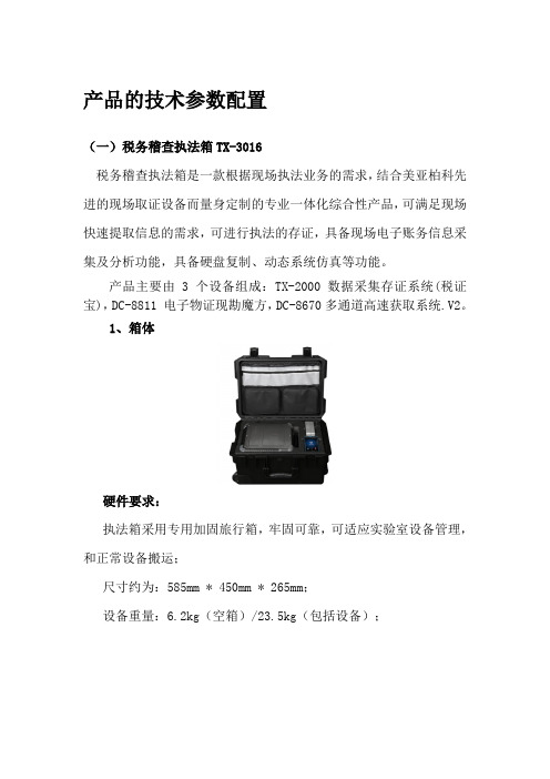
产品的技术参数配置(一)税务稽查执法箱TX-3016税务稽查执法箱是一款根据现场执法业务的需求,结合美亚柏科先进的现场取证设备而量身定制的专业一体化综合性产品,可满足现场快速提取信息的需求,可进行执法的存证,具备现场电子账务信息采集及分析功能,具备硬盘复制、动态系统仿真等功能。
产品主要由3个设备组成:TX-2000 数据采集存证系统(税证宝),DC-8811 电子物证现勘魔方,DC-8670多通道高速获取系统.V2。
1、箱体硬件要求:执法箱采用专用加固旅行箱,牢固可靠,可适应实验室设备管理,和正常设备搬运;尺寸约为:585mm * 450mm * 265mm;设备重量:6.2kg(空箱)/23.5kg(包括设备);2、DC-8811 电子物证现勘魔方电子物证现勘魔方和数据采集存证系统是一款根据现场执法业务的需求,结合厦门美亚柏科先进的现场取证设备而量身定制的专业一体化综合性产品,可满足现场快速提取信息的需求,可进行执法的存证,具备现场电子账务信息采集及分析功能,具备硬盘复制、动态系统仿真等功能。
电子物证现勘魔方是一款专为执法部门现场进行勘查分析设计的电子物证采集分析一体化设备,该产品采用全球领先的高速硬盘复制、自动取证分析、动态系统仿真等多种先进技术并行处理,同时提供了符合司法有效性的写保护功能,使得现场进行证据固定、电子物证调查分析工作简单快捷,大大提高现场勘查检验人员的效率。
硬件要求:●采用一体化设计,配备10.1"电容触摸屏,轻巧便携;●高性能配置,采用四核八线程CPU,配置16G内存,配置1T 容量硬盘;●专机专用,采用64位嵌入式操作系统;●国内自主研发,具有独立自主知识产权;硬盘复制部分:●支持2路并行复制功能,并提供SATA/SAS免接线直插式只读接口;●源盘只读接口支持分别或同时对硬盘进行加载/卸载;●支持IDE、SATA、SAS、USB等只读接口硬盘的高速复制,复制速度最高可达27GB/min;●配备USB3.0只读接口,支持对USB3.0设备进行高速复制;●硬盘复制功能支持一对一、一对二、二对二复制;●硬盘镜像功能支持一对一、一对二、二对二DD、E01、AFF镜像复制模式;●支持HPA/DCO隐藏区域的自动识别及数据获取;●支持对目标计算机进行不拆机硬盘复制;●支持对现场中断情况进行自动恢复操作;●支持在硬盘复制或镜像时进行关键词搜索,并可将结果直接导入内置调查分析软件进行分析●并行工作能力,可在硬盘复制的同时支持对数据进行调查分析以及系统仿真分析;●支持将硬盘镜像文件直接还原到硬盘;一键调查部分:●提供一键式、便捷的调查分析功能;●支持通过默认的方式进行快速调查,同时支持用户痕迹、上网记录、文件分析等十多种筛选功能;●支持通过默认的方式进行快速的检索,同时支持在指定时间区间或指定内容的检索功能;●支持后台自动索引功能,提高检索效率;取证分析部分:●支持Mac OS X系统,Windows系统(包含Win8),Linux系统的取证●支持基本磁盘/动态磁盘,MBR磁盘/GPT磁盘,LDM/LVM磁盘,磁盘阵列重组,支持FAT12、FAT16、FAT32、exFAT、NTFS、CDFS、UDF、Ext2/3/4、HFSX/HFS+ UFS、ReiserFS、以及手机上的YAFFS2、ROFS等多种文件系统格式的解析,及多种被删除数据的恢复;●支持E01、Ex01、L01、DD、Img、001、ISO、Dmg、VMDK、VHD、AFF等镜像文件的加载和分析;●支持被删除分区的恢复,分析效率快,分析定位准确。
Pepperl+Fuchs 控制站操作说明书
Operation InstructionsControl StationsFXL****.CS / XL****.CS / GL***.CSCopyright Pepperl+FuchsPart No.:Document No.:Edition: 08/2014Pepperl+Fuchs GmbH Lilienthalstrasse 20068307 Mannheim, Germany Tel. +49 621 776-0Fax +49 621 776-1000ENGValiditySpecific processes and instructions in this document require special precautions to guarantee the safety of the operating personnel.Target Group/PersonnelResponsibility for planning, assembly, commissioning, operation, maintenance, and dismounting lies with the system operator.Mounting, installation, commissioning, operation, maintenance anddisassembly of any devices may only be carried out by trained, qualified personnel. The instruction manual must be read and ws, standards, or directives applicable to the intended use must be observed. In relation to hazardous areas, Directive 1999/92/EC must be observed.The corresponding data sheets, declarations of conformity, EC-type-examination certificates, certificates and Control Drawings if applicable (see data sheet) are an integral part of this document. You can find this information under .Mounting/InstallationUse only one conductor per terminal.■If cable glands are needed for installation, the following points must be considered / evaluated:■The cable glands used must be suitably certified for the application■The temperature range of the cable glands must be chosen according tothe application.■The cable glands fitted must not reduce the IP rating.If you use stranded wires, crimp on wire end ferrules.In order to guarantee the temperature classes, ensure that power dissipation is lower than the figure stated in the certificate. Most of the power dissipation arises from current flowing in the cables.In order to minimize power dissipation, observe the maximum possible cable lengths.Observe the tightening torque of the terminal screws.Unused conductors must be either connected to terminals or securely tied down and isolated.If mounting the enclosure on concrete use expanding bolts. If mounting the enclosure to a steel framework use vibration resistant mounting equipment.The insulation stripping length must be considered.To ensure the IP degree of protection:■all seals must be undamaged and correctly fitted■all screws of the surrounding enclosure and its cover must be tightened with the appropriate torque■only cable of the appropriate size must be used in the cable glands ■all cable glands must be tightened with the appropriate torque■all empty cable glands must be sealed with the corresponding plugsWhen installing additional components, make sure that these components are listed in the EC-Type-Examination Certificate of the control station.Select suitable conductors in order to ensure, that the maximum permitted temperature of the conductors fit to the maximum permitted ambient temperature of the control station.The permitted ambient temperatures of the built-in components must not be exceeded.The minimum bending radius has to be adhered to.When installing the conductors the insulation must reach up to the terminal.In order to prevent condensation in the enclosure, use suitable certified breathers.Connect all bare non-energized metal parts to the protective earth conductor.Observe IEC/EN 60079-17 for maintenance and testing.Before opening the enclosure make sure, that the built-in components are de-engergized.When energized, the enclosure may only be opened for maintenance, if only intrinsically safe circuits are used inside the enclosure.If there is a defect, the product must be repaired by Pepperl+Fuchs.When the internal/external ground bolt is supplied loose, the components should be fitted as shown in the figure below.Technical Specifications1Enclosure wall 2Enclosure exterior 3Enclosure interior(F)XL******.CS (formerly .CP)GL*****.CS (formerly .CP)Refer to type code builder in chapter …Typecodes“Refer to type code builder in chapter …Typecodes“Hazardous Area ATEX certificate number SIRA13ATEX3059XIECEx certificate number IECEx SIR 13.0021 (no IECEx for Control Stations fitted withSchmersal controls)CE numberCertification coding for ATEX/IECEx Certification digit in type code 1II 2 GD Ex de IIC T* Gb II 2 GD Ex tb IIIC T** DbCertification digit in type code 3II 2 GD Ex ib IIC T* Gb II 2 GD Ex tb IIIC T** DbCertification digit in type code 5II 2 GD Ex de ib IIC T* Gb II 2 GD Ex tb IIIC T** DbGas/dust temperature class Maximum ambient temperatureTa +55°CTa +40°C Applications with 5°K internal riseT5 / T95°C T6 / T80°C Applications with 10°K internal riseT4 / T130°C T6 / T80°C Applications with 15°K internal riseT4 / T130°C T5 / T95°C When Schmersal controls fittedT4 / T130°CT4 / T130°CRefer to the enclosure certification label for confirmation Minimum ambient temperature -40°C (-25°C / 0°C when fitted with Schmersal controls)-50°C with specific equipment optionsIP RatingIP 66 (IP 65 when fitted with Schmersal controls)0102Dissipation of copper cables in W/mMaximum internal power dissipation (MDP)Dependent on enclosure size and application internal rise – see certification labelMechanical XL/FXL types MaterialStainless steel models 316L Mild steel modelsCR4FinishStainless steel models Electropolished Mild steel modelsPowder coatedGL types Material Glass reinforced polyester FinishAs mouldedAll typesCover screw torque 2 NmEntry threadform Refer to Customer Specific Drawing produced at time of orderingElectrical Maximum voltageDependent on terminals & equipment fitted – see certification labelMaximum currentDependent on terminals, cable & equipment fitted – see certification label ConformityEN 60079-0: 2012EN 60079-7: 2007EN 60079-31: 2009EN 60079-1: 2007EN 60079-11: 2007EN 60529Current (A)Cable CSA 124610161 mm 20.01680.06720.2690.605 1.68 4.32.5 mm 20.006720.02690.1080.2420.672 1.724 mm 20.00420.01680.0670.1510.42 1.086 mm20.00280.01120.0450.1010.280.717(F)XL******.CS (formerly .CP)GL*****.CS (formerly .CP)Refer to type code builder in chapter …Typecodes“Refer to type code builder in chapter …Typecodes“Typecodes(F)XL*.CS Typecode:GL*.CS Typecode:。
CR-Series 毯杆说明书

CR-SERIES C ARPET P OLES I NSTRUCTION M ANUALReceiving instructions:After delivery, IMMEDIATELY remove the packaging from the carpet pole in a manner that preserves the packaging and maintains the orientation of the product in the packaging; then inspect the product closely to determine whether it sustained damage during transport. If damage is discovered during the inspection, immediately record a complete description of the damage on the bill of lading . If the product is undamaged, discard the packaging.NOTES:1) Compliance with laws, regulations, codes, and non-voluntary standards enforced in the location where the product is used is exclusively the responsibility of the owner/end-user.2) VESTIL is not liable for any injury or property damage that occurs as a consequence of failing to apply either: a) Instructions in this manual; or b) information provided on labels affixed to the product. Neither is Vestilresponsible for any consequential damages sustained as a result of failing to exercise sound judgment while assembling, installing, using or maintaining this product.V ESTIL M ANUFACTURING C ORP .2999 North Wayne Street, P.O. Box 507, Angola, IN 46703 Telephone: (260) 665-7586 -or- Toll Free (800) 348-0868Fax: (260) 665-1339 e-mail:Each person who assembles, installs, uses, or maintains this product should read the entire manualSAFETY GUIDELINESVestil diligently strives to identify foreseeable hazards associated with the use of its products. However, material handling is inherently dangerous and no manual can address every conceivable risk. The end-user ultimately is responsible for exercising sound judgment at all times.Electrocution might result if any part of the pole, fork truck, or carpet roll contacts electrified wires.Reduce the likelihood of electrocution by applying common sense :DO NOT contact electrified wires with any part of the pole, the fork truck, or the roll of carpet;Before using the carpet pole, inspect the usage area implement precautions that account for electrical hazards. If this product is used improperly or carelessly, the operator and/or bystanders might sustain seriouspersonal injuries or even be killed. ALWAYS use the product properly:∙ Failure to read and understand the entire manual before assembling, installing, using or servicing the product is a misuse of the product . Read the manual to refresh your understanding of proper use and maintenance procedures.∙ DO NOT exceed the maximum rated load (see Label 287 on product; also shown on p. 9). ∙ Inspect the carpet pole before each use.A. DO NOT use this device if the inspection reveals structural damage. Examples of structural damage include: 1)broken, missing, or deformed carriage brackets (item no. 1.4, p. 4 & 5); 2) damaged or deformed latch lever or spring latch (items 9 & 11, p. 4 & 5); 3) cracked welds; 4) enlarged openings for fasteners (i.e. pins and bolts used to fasten the pole to the carriage weldment (item 1, p. 4 & 5) ; 5) corrosion, severe wear, or other condition that affects the ability of the product to support the weight of a roll of carpet. Replace each part that fails to pass an inspection, and DO NOT use the product until it is fully restored to normal condition.B. DO NOT use the product if any unusual noise or movement is observed prior to engaging a roll of carpet.Immediately unload the carpet pole if unusual movement or sound is observed during use. If a malfunction occurs, remove the unit from service and notify your supervisor & maintenance personnel about the issue. ∙ Before attaching the carpet pole to the carriage of your fork lift, inspect the carriage and confirm that all parts are structurally sound and in nominal condition. ∙ Always test the soundness of the connection between the carriage weldment of the carpet ram and the carriage of the fork truck before driving the fork truck with a loaded carpet pole, by lifting the roll just a few inches off of the ground. Load swing should be minimal and the carpet pole should not shift. If the load is not stable while supported by the pole, return it to the ground and use another means to transport the roll of carpet. ∙ ALWAYS apply all rules governing use of fork lift attachments applied at your work site. ∙ DO NOT remove or obscure any label. Verify the placement and legibility of all labels as shown in the Label Placement Diagram on p. 8. DO NOT use this device UNLESS all product labels are readable and undamaged. ∙ DO NOT ride or sit on, or allow others to ride or sit on the carpet pole.∙ DO NOT use the carpet pole as a means to push another object. Only use the product to transport a roll of carpet. ∙ ONLY use this forklift attachment on firm, level, even ground.∙DO NOT leave elevated rolls of carpet unattended. Always move the roll to its desired location, and then disengage it from the carpet pole and properly immobilize it before leaving the roll unattended.∙DO NOT modify the carpet pole in any way UNLESS you first obtain written approval from Vestil. Unauthorized modifications automatically void the limited warranty (see p. 10) and might make the product unsafe to use.Proper use, maintenance, and storage are essential for this product to function properly.o Always use this product in accordance with the instructions in this manual and consistent with any training relevant to forklift attachments.o Keep the carpet pole as well as all associated attachments clean & dry.Product SpecificationsCR-series Carpet PolesModel Length in inches(~cm)Pole diameter ininches (~cm)Capacity inpounds (~kg)Net WeightCR-108-2108(~274cm)2¾(~7cm)2,500(~1136kg)287(~130.5kg)CR-120-2120(~305cm)2¾(~7cm)2,200(~1000kg)421(~191.4kg)CR-144-2144(~366cm)2¾(~7cm)1,800(~818kg)478(~217.3kg)CR-108-3108(~274cm)2¾(~7cm)2,500(~1136kg)397(~180.5kg)CR-120-3120(~305cm)2¾(~7cm)2,200(~1000kg)421(~191.4kg)CR-144-3144(~366cm)2¾(~7cm)1,800(~818kg)478(~217.3kg)FIG. 1: Class 2 carriage CR-series carpet poles exploded parts diagramItemno. Part no.Description Quantity1 08-538-001 Carriage weldment backplate 1 1.4 08-016-056 CR-2 series bolt-on lower bracket 1 208-514-092 08-514-093 08-514-094Pole frame weldment CR-108-2 CR-120-2 CR-144-2 1 1 1 3 23525 5/8 in. – 11 x 6in. grade 8 SHCS bolt 3 4 36414 5/8 in. – 11 grade 8 UNC hex nut 3 5 33692 5/8 in. high collar lock washer 3 6 123135/8 in. – 11 x 2½ in. grade 8 SHCS bolt for lower carriage bracket1 7 33630 Medium split lock washer 18 08-145-021 Latch pin 1 9 08-145-020 Latch lever 1 10 08-145-022 Latch rivot 1 11 08-146-004 Latch spring1Torque specifications for item numbers 3 and 6:∙ Item no. 3 (pole mounting bolts; 5/8 in. – 11 x 6in. grade 8 SHCS bolt) should be fastened to hex nuts (item no. 4) with 238 ft*lbs. of torque. ∙ Item no. 6 (5/8 in. – 11 x 6in. grade 8 SHCS bolt for lower carriage bracket) should be fastened to the bracket using 135 ft*lbs. of torque.FIG. 2: Class 3 carriage CR-series carpet poles exploded parts diagramItemno. Part no.Description Quantity1 08-538-002 Carriage weldment backplate 1 1.4 08-016-039 CR-3 series bolt-on lower bracket 1 208-514-092 08-514-093 08-514-094Pole frame weldment CR-108-3 CR-120-3 CR-144-3 1 1 1 3 23525 5/8 in. – 11 x 6in. grade 8 SHCS bolt 3 4 36414 5/8 in. – 11 grade 8 UNC hex nut 3 5 33692 5/8 in. high collar lock washer 3 6 123135/8 in. – 11 x 2½ in. grade 8 SHCS bolt for lower carriage bracket1 7 33630 Medium split lock washer 18 08-145-021 Latch pin 1 9 08-145-020 Latch lever 1 10 08-145-022 Latch rivot 1 11 08-146-004 Latch spring1Torque specifications for item numbers 3 and 6:∙ Item no. 3 (pole mounting bolts; 5/8 in. – 11 x 6in. grade 8 SHCS bolt) should be fastened to hex nuts (item no. 4) with 238 ft*lbs. of torque. ∙ Item no. 6 (5/8 in. – 11 x 6in. grade 8 SHCS bolt for lower carriagebracket) should be fastened to the bracket using 135 ft*lbs. of torque.Attaching carpet pole to lift truckStep 1: Referring to FIG. 1 & 2 on p. 4 & 5, remove item no. 6 (bolt for lower carriage bracket) and item no. 1.4.Step 2: Remove the tines from the lift truck carriage. Referring to the diagram below, rotate the latch lever to the open position. Tilt the mast of your lift truck forward and then engage the top carriage bracket of the carpet pole with the upper carriage crossbar of your lift truck.Step 3: Lean the fork truck mast back until the lower carriage crossbar contacts the carriage backplate weldment (item no. 1 on p. 4 & 5); then adjust the position of the weldment on the carriage crossbars to center the carpet pole on the carriage. Rotate the latch lever back to the closed position. NOTE: The latch lever will only rotate back to the closed position if the latch aligns with a notch on the crossbar. Adjust the position of the carpet pole on the carriage crossbar until the latch aligns with a notch.Rear view of carriage backplate weldment Forklift carriageLower carriage bracketUpper carriage bracket Forkcarriage crossbarUpper bracket with latch.Turn latch to open position Fork truck mastLower carriage bracketBolt for lower carriage bracketBackplate carriage weldmentStep.4: Install the lower carriage bracket. Referring to the diagram below, install the lower carriage bracket and fasten it with bolt (item no. 6) with 135 ft*lbs of torque.Inspections & Maintenance:Inspection and maintenance personnel should immobilize the boom before either conducting inspectionsor performing maintenance. The boom is properly immobilized if it cannot tip over.If one or more problem is discovered during an inspection, restore the carpet pole to normal operating condition BEFORE using it again. DO NOT use the pole if it is structurally damaged in any way. Structural damage includes, but is not limited to, cracked welds, warping or deformation of the pole, carriage brackets, or frame members.CR-series function like a hoist-less crane: instead of using a hoist to lift loads, the bridge girder rises and lowers through the movement of the forks of a lift truck. Therefore, boom owners/end-users should inspect the boom regularly following an established process. An example of an inspection procedure appears in 29 CFR 1910.179 (visit / and navigate to “Regulations” section 1910.179). Paraphrased, relevant portions appear below:1. Initial inspection — before a new or modified crane (boom) may be used for the first time, it must be inspected to insure normal condition.After the first use, the boom end-user/owner must conduct the following 2 types of inspection:2. Frequent inspection — Daily to monthly intervals.The following items shall be inspected for defects at the intervals specifically indicated, including observation during operation for any defects which might appear between inspections. All deficiencies such as those listed shall be carefully examined to determine whether they constitute a safety hazard:[Inspect daily] All functional operating mechanisms (pole, carriage brackets, lever latch, carriage weldment backplate, and all fasteners for maladjustment or damage that might interfere with proper operation. Inspect the carpet pole for:1. Dirt or other matter on the surface;2. Integrity of hardware and fasteners, including but not limited to bolts, nuts, pins, springs;3. Normal operability of manually (by hand or foot) operated mechanisms;4. Abnormal or noisy movement during use;Lift truck mast Upper carriage crossbar Carriage backplate weldment Lower carriage bracket Item no. 6 (5/8 in. – 11 x 6in.grade 8 SHCS bolt for lower carriage bracket) should be fastened to the bracket using 135 ft*lbs. of torque Lower carriage crossbar5. Looseness or excessive wear of, damage to, or indications of metal fatigue in any portion of the pole of thecarriage backplate weldment, especially the clamp mechanism that grips the end of the pole and the carriage brackets that attach the carpet pole to the forklift carriage;6. Damaged or unreadable labels;7. Evidence of corrosion or rust-related metal erosion.3. Periodic inspection [29 CFR 1910.179(j)(1)(ii)(b)] — 1-to-12 month intervals.Inspect the entire carpet pole apparatus at intervals that correspond to its frequency of use, severity of service, and environment, or as specifically indicated below. Perform all of the applicable “Frequent inspection” steps and carefully examine the carpet pole for any the problems that appear below to determine whether they constitute a safety hazard: ∙Deformed, cracked, or corroded members.∙Loose fasteners (bolts or rivets).Carpet pole not in regular use:For each of the 3 bullet points below, in addition to the inspections, any carpet pole which has been idle for a period of a month or more must be given a thorough inspection before it is used again. An appointed person, whose approval is required before the pole may be used, should inspect the product for all types of deterioration.∙If idle for a period of 1 month (or longer), but less than 6 months, perform a “Frequent inspection” before returning it to service.∙ A boom which has been idle for longer than 6 months shall be given a “Periodic [complete] inspection” before placing it in service.∙Standby booms shall be given a frequent inspection at least semi-annually (twice per year; 1 inspection each 6 months).Annual performance evaluation: At least once per year, authorized inspection personnel should verify the soundness of the boom. Use the carpet pole to lift a maximum rated load. Afterwards, conduct a “Frequent inspection” to verify that the product is in normal operating condition.Maintenance:The end-user, i.e. operators and operators’ employer, must implement a maintenance program to ensure that the product functions properly and is adequately maintained. OSHA “General Industry” standards applied to “Powered industrial trucks,” 29 CFR 1910.178, describe official, recommended maintenance procedures. The following steps should be utilized in conjunction with those recommendations.The end-user is responsible for selecting and training employees to work on the carpet pole. “Work on” refers to attaching, loading, cleaning, servicing, maintaining, or repairing the product. ONLY trained, authorized maintenance personnel or contractors should perform inspection, maintenance, or repair work.Step 1: Tag the pole, “Out of Service.”Step 2: Remove any dirt or other matter from all surfaces.Step 3: Conduct a “Before each use” inspection. If deformity, corrosion, rusting, or excessive wear of structural members is found, DO NOT use the product.Step 4: Perform all other necessary adjustments, replacements and/or repairs. DO NOT modify the boom.The reader should understand the significant difference between necessary adjustments and repairs, and modifications.An “adjustment” is a simple correction that restores the boom to normal operating condition, such as tightening loose fasteners, or removing dirt or other debris from the surface. “Repair” refers to removing worn parts and installing replacement parts.DO NOT use the carpet pole if adjustments and/or repairs are incomplete! Return it to service ONLY after finishing all necessary repairs and adjustments.A “modification” is a change that alters the carpet pole from normal operating condition, like bending the structural members or removing a part or several parts. NEVER modify the boom without the express, written approval of Vestil. Modifications may render the device unsafe to use.Step 5: Make a dated record of any repairs, adjustments and/or replacements.LIMITED WARRANTYVestil Manufacturing Corporation (“Vestil”) warrants this product to be free of defects in material and workmanship during the warranty period. Our warranty obligation is to provide a replacement for a defective original part if the part is covered by the warranty, after we receive a proper request from the warrantee (you) for warranty service.Who may request service?Only a warrantee may request service. You are a warrantee if you purchased the product from Vestil or from an authorized distributor AND Vestil has been fully paid.What is an “original part”?An original part is a part used to make the product as shipped to the warrantee.What is a “proper request”?A request for warranty service is proper if Vestil receives: 1) a photocopy of the Customer Invoice that displays the shipping date; AND 2) a written request for warranty service including your name and phone number. Send requests by any of the following methods:Mail Fax EmailVestil Manufacturing Corporation (260) 665-1339 ****************2999 North Wayne Street, PO Box 507 PhoneAngola, IN 46703 (260) 665-7586In the written request, list the parts believed to be defective and include the address where replacements should be delivered.What is covered under the warranty?After Vestil receives your request for warranty service, an authorized representative will contact you to determine whether your claim is covered by the warranty. Before providing warranty service, Vestil may require you to send the entire product, or just the defective part or parts, to its facility in Angola, IN. The warranty covers defects in the following original dynamic components: motors, hydraulic pumps, electronic controllers, switches and cylinders. It also covers defects in original parts that wear under normal usage conditions (“wearing parts”): bearings, hoses, wheels, seals, brushes, batteries, and the battery charger.How long is the warranty period?The warranty period for original components is 90 days. The warranty period begins on the date when Vestil ships the product to the warrantee. If the product was purchased from an authorized distributor, the period begins when the distributor ships the product. Vestil may extend the warranty period for products shipped from authorized distributors by up to 30 days to account for shipping time.If a defective part is covered by the warranty, what will Vestil do to correct the problem?Vestil will provide an appropriate replacement for any covered part. An authorized representative of Vestil will contact you to discuss your claim.What is not covered by the warranty?1. Labor;2. Freight;3. Occurrence of any of the following, which automatically voids the warranty:∙ Product misuse;∙Negligent operation or repair;∙Corrosion or use in corrosive environments;∙Inadequate or improper maintenance;∙Damage sustained during shipping;∙Collisions or other incidental contacts causing damage to the product;∙ Unauthorized modifications: DO NOT modify the product IN ANY WAY without first receiving written authorization from Vestil. Modification(s) might make the product unsafe to use or might cause excessive and/or abnormal wear.Do any other warranties apply to the product?Vestil Manufacturing Corp.makes no other express warranties. All implied warranties are disclaimed to the extent allowed by law. Any implied warranty not disclaimed is limited in scope to the terms of this Limited Warranty.。
升腾科技Ys31000006笔记本电脑说明书
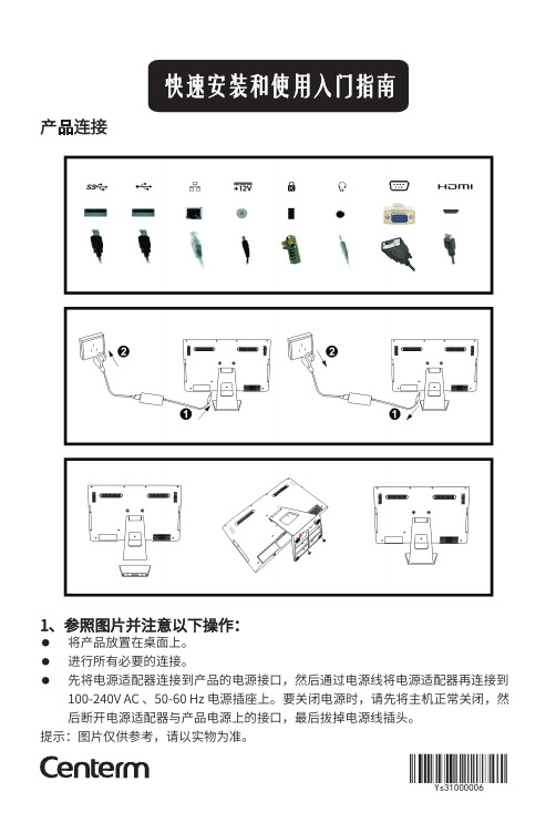
产品连接1、参照图片并注意以下操作:将产品放置在桌面上。
进行所有必要的连接。
先将电源适配器连接到产品的电源接口,然后通过电源线将电源适配器再连接到100-240V AC 、50-60Hz 电源插座上。
要关闭电源时,请先将主机正常关闭,然后断开电源适配器与产品电源上的接口,最后拔掉电源线插头。
提示:图片仅供参考,请以实物为准。
Ys31000006警告:2、警告声明若不当连接、安装、使用本产品,可能导致组件故障或造成产品损坏。
在安装和操作产品之前,请阅读以下警告声明。
安装 完成所有连接(包括电源适配器)之后才能连接到交流电源。
当产品接通交流电源后,断开组件或设备,可能会产生电涌,导致产品受损。
请勿强行将插头插入其插槽内。
如果遇到阻力过大,请确保插头插入插槽的方向正确。
使用环境为延长设备的使用寿命,建议工作环境:温度0℃-40℃,湿度:30%-90%RH .方向和通风按照图示安装产品,或者根据升腾提供的安装配件包提供的说明进行安装。
方向不正确可能会阻碍设备散热,从而导致设备损坏。
在产品周围留出足够空间,用于通风。
请勿将产品置于任何限制产品周围空气流通的密闭空间内。
请勿将任何物体置于产品上或阻挡产品的散热孔。
电源请务必使用产品随附的电源适配器,或是升腾认证的同等装置。
为了正确替换,请比较 意外断电可能损坏产品,请避免将产品连接到有可能意外切断的电源插座上。
正常运行时,请不要通过按住电源按钮来硬复原产品。
关闭产品时,请确保执行完整的关闭操作(通过用户界面或轻按电源按钮)。
在闪电多发地区,建议为电子设备安装电涌保护器。
但是在闪电发生时,应正确使用设备并拔去交流电源插头,直到暴风雨过去后再插入电源。
请务必注意,在产品进行软件更新时请切勿中断电源。
切勿将水或其他液体泼洒在设备上,一旦发生这种情况,应立即断开设备电源。
电池产品包含一个内置的纽扣电池,可由本公司或授权服务中心更换。
若需相关服务请联系本公司或者授权服务中心。
InspireX R50G 高速X射线检测仪产品说明书

I n s p e c c i ón p o r r a y o s XInspección integral de vidrio en vidrio2Los sistemas de rayos X InspireX R50G ofrecen una inspección automática óptima de tarros de vidrio de densidad alta y media. Permite una detección excepcional de cuerpos extraños, como vidrio de material férrico, no férrico y de aceroinoxidable, piedras minerales, huesos calcificados y plásticos de alta densidad. Asimismo, puede realizar simultáneamente un gran número de controles de calidad en línea, incluida la supervisión del nivel de llenado.I n s p e c c i ón p o r r a y o s XInspireX R50GInspección integral de vidrio en vidrioFunciones de software•Las herramientas de software XTP recientemente desarrolladas analizan los productos con la mayor resolución posible y, de esta forma, permiten alcanzar unos niveles de deteccióninsuperables, sobre todo en las zonas más complicadas de los envases de vidrio.•Configuración completamente automatizada que garantiza un máximo tiempo de funcionamiento de la producción.•El filtrado a medida permite que los filtros de perfil exterior de los envases cambien de forma dinámica para cada envase, lo que garantiza una detección óptima y un mínimo de falsos rechazos.•ProdX: las opciones del software de gestión de datos de inspección de productos proporcionan una gran cantidad de información en tiempo real para la gestión de la producción, lo que permite el control eficaz de los dispositivos y procesos de inspección de productos.Diseño e higiene•Diseño higiénico puntero en su categoría, según las pautas GMP , NSF y EHEDG.•IP65 de serie e IP69K disponible como opción para entornos hostiles de lavado.•Fácil acceso a todas las zonas de la máquina, sin recovecos proclives a la proliferación de bacterias, lo que garantiza un tiempo de inactividad mínimo y una protección óptima frente a microorganismos patógenos.• Allí donde era posible, se han colocado superficies inclinadas para evacuar el agua.Flexibilidad y seguridad•Generador de rayos X de 360 W para una amplia gama de envases de vidrio.•La velocidad de exploración con rayos X se sincroniza automáticamente con lavelocidad de la cinta del cliente, manteniendo una relación de imagen de uno a uno. No se requiere ningún ajuste manual, lo que garantiza el máximo tiempo de funcionamiento de la línea de producción, así como la optimización de la detección y del rechazo.Auditorías y verificación•Trazabilidad estadística completa para creación de informes de calidad.• Las imágenes y las estadísticas se guardan tras el apagado, lo que garantiza el mantenimiento de datos sensibles.•Verificación del rendimiento integrada para garantizar un rendimiento óptimo de forma continua.•Todos los informes e imágenes se pueden descargar a un dispositivo USB o a través de una red, por lo que no hay necesidad de conservar registros en papel.•Las opciones de confirmación de rechazo y de alarma de contenedor lleno garantizan una eficacia del 100 % en el rechazo de la línea.Instalación rápida, fácil y rentable•Sistema completamente integrado que incluye la transferencia, la inspección y el transportador de rechazos, lo que hace que el tiempo de instalación y el coste total de propiedad se reduzcan considerablemente.•InspireX R50G se suministra con el haz de rayos X prealineado con el transportador de rayos X integrado, de tal manera que tan solo es necesario realizar un mínimo alineamiento con el transportador del cliente.•Las emisiones de rayos X semantienen dentro de la estructura, lo que hace innecesario el uso de pantallas de protección adicionales en el transportador del cliente.Software de gestión y control de datos Prod X .3El sistema de inspección por rayos X InspireX R50G no tiene rival en la inspección vidrio en vidrio, ya que elimina los puntos ciegos tradicionales de la base, de las paredes laterales y del cuerpo de los envases de vidrio, además de ofrecer comprobaciones precisas del nivel de llenado de altura máxima. Asimismo, optimiza la eficiencia de la línea de producción y contribuye a que los fabricantes de alimentos se pongan por delante de sus competidores, al mismo tiempo que garantiza el cumplimiento de la normativa y demuestra la diligencia debida.El transportador de transferencia en tres etapas InspireX R50G permite transferir con fluidez el producto desde el transportador del cliente hasta el transportador principal de rayos X.Vista frontal de InspireX R50G.Diagrama del haz de InspireX R50G, que muestra dos ejemplos deanchuras y alturas de tarro diferentes.Imagen de rayos X que muestra la detección de vidrio de 2,5 mm en la base del tarro.Imagen de rayos X que muestra la detección de vidrio de 2 mm en las paredes laterales del tarro.Imagen de rayos X que muestra una inspección precisa del nivel de llenado.InspireX R50GPara más informaciónMettler-Toledo S.A.E.Miguel Hernández, 69-7108908 L’Hospitalet de Llobregat Barcelona, EspañaTel.: +34 902 32 00 23Fax: +34 902 32 00 24Correoelectrónico:*************Sujeto a cambios técnicos.© 05/2013 Mettler-Toledo Safeline X-ray Ltd.Impreso en el Reino Unido./safeline-xrayTabla de especificacionesHay varios tipos disponibles de sistemas de rechazo de alta velocidad completamente integrados.La elección correcta depende de varios factores, como el tipo de entorno, la velocidad de la cinta y el peso, el tipo y el tamaño del envase. Todos los sistemas de rechazo disponen de verificación de rechazo opcional, que garantiza que un producto defectuoso acaba en el contenedor de rechazo y verifica que el sistema de rechazo funciona.Mecanismos de rechazoSistema de rechazo de empujador lateral de cortoalcance de alta velocidad.。
悍马汽车部件维修指南说明书

Cutoff Indicator Works........... 49
How Your Front Airbags Work.......................................... 46
CONTINUED
I
v w
Main Menu
Index
Bulb Replacement Back-up Lights ........................... 206 Stop Light ................................... 206 Cargo Area Light ....................... 211 Front Parking Lights................. 205 Front Side Marker Lights......... 204 Headlights .................................. 202 High-mount Brake Light .......... 207 Interior Lights............................ 210 License Plate Lights.................. 209 Side Marker Lights ................... 204 Side Turn Signal Lights ............ 208 Specifications ............................. 251 Turn Signal Lights..................... 203
PurePath Console Motherboard用户指南说明书

User's GuideSLOU366B–June2013–Revised February2015PurePath TM Console Motherboard This manual describes the operation of the PurePath™Console Motherboard(PPCMB),revisions D,E,and F.The PPCMB connects to device under test(DUT)boards.These can be evaluation modules(EVM) or reference boards(REF).The PurePath Console graphical user interface(PPC)is used to initialize andoperate the PPCMB and the DUT.The main contents of this document are:•Hardware implementation and descriptions•Software implementation and descriptions•System operations(hardware and software)•Example with TAS5760xEVM(DUT)Contents1Hardware Overview (3)1.1PurePath Console Motherboard Features (4)1.2PurePath Console Motherboard Functions (4)1.3PurePath Console Motherboard Detailed Operations (5)2PurePath Console Motherboard Setup and Software Installation (6)2.1PurePath Console Motherboard Setup (6)2.2Software Installation (7)3Using the PurePath Console Software with the PurePath Console Motherboard (9)3.1Device Main Tab (9)3.2Device Block Diagram Tab (9)3.3Pop-up Windows (10)3.4Direct I2C Access Tab (11)3.5Device Registers Tab (11)4Board Layouts,Bill of Materials,and Schematic (12)4.1PurePath Console Motherboard Layouts,Revisions D and E (12)4.2PurePath Console Motherboard Layouts,Revision F (14)4.3Bill of Materials (16)4.4PurePath Console,Revision D and E,Schematic (28)4.5PurePath Console,Revision F,Schematic (38)List of Figures1PurePath Console Motherboard Revision D (3)2PurePath Console Motherboard Signal Flow(Revisions D and E) (4)3Device Manager (5)4PurePath Console Motherboard Connection (6)5Target Selection List (7)6Add Target List (8)7PurePath Console Motherboard and TAS5760xEVM (8)8DUT Block Diagram(TAS5760) (9)9Digital Gain Pop-Up (10)10Analog Gain Pop-Up (10)11Direct I2C Access (11)PurePath,MPS430are trademarks of Texas Instruments.Windows is a registered trademark of Microsoft Corporation.All other trademarks are the property of their respective owners.1 SLOU366B–June2013–Revised February2015TM 12Device Registers Tab (11)13PurePath Console Motherboard,Revision D and E,Top Composite Assembly (12)14PurePath Console Motherboard,Revision D and E,Copper Layer2 (12)15PurePath Console Motherboard,Revision D and E,Copper Layer3 (13)16PurePath Console Motherboard,Revision D and E,Bottom Composite Assembly (13)17PurePath Console Motherboard,Revision F,Top Composite Assembly (14)18PurePath Console Motherboard,Revision F,Copper Layer2 (14)19PurePath Console Motherboard,Revision F,Copper Layer3 (15)20PurePath Console Motherboard,Revision F,Bottom Composite Assembly (15)21PurePath Console Revisions D and E(1of10) (28)22PurePath Console Revisions D and E(2of10) (29)23PurePath Console Revisions D and E(3of10) (30)24PurePath Console Revisions D and E(4of10) (31)25PurePath Console Revisions D and E(5of10) (32)26PurePath Console Revisions D and E(6of10) (33)27PurePath Console Revisions D and E(7of10) (34)28PurePath Console Revisions D and E(8of10) (35)29PurePath Console Revisions D and E(9of10) (36)30PurePath Console Revisions D and E(10of10) (37)31PurePath Console Revision F(1of12) (38)32PurePath Console Revision F(2of12) (39)33PurePath Console Revision F(3of12) (40)34PurePath Console Revision F(4of12) (41)35PurePath Console Revision F(5of12) (42)36PurePath Console Revision F(6of12) (43)37PurePath Console Revision F(7of12) (44)38PurePath Console Revision F(8of12) (45)39PurePath Console Revision F(9of12) (46)40PurePath Console Revision F(10of12) (47)41PurePath Console Revision F(11of12) (48)42PurePath Console Revision F(12of12) (49)43PurePath Console Revisions D,E,and F (50)List of Tables1Bill of Materials,Revision D (16)2Bill of Materials,Revision E (19)3Bill of Materials,Revisions F (23) Hardware Overview 1Hardware OverviewThe PPCMB provides control signals and audio signals to the DUT.The PPC sends the control signals to the TAS1020B device through the USB human-interface device(HID)protocol.The TAS1020B deviceconverts to I2C and sends to the appropriate I2C address.The audio signals are provided through USB audio,SPDIF,or analog signals.The aforementioned signals are converted to I2S–see Figure2.Figure1.PurePath Console Motherboard Revision D3 SLOU366B–June2013–Revised February2015TMHardware Overview Figure2shows the PPCMB Revisions D and E signal flow.For Revision F,refer to the block diagram in Section4.5.Figure2.PurePath Console Motherboard Signal Flow(Revisions D and E)1.1PurePath Console Motherboard Features•The PPC sends I2C control signals through the USB link:the initialization sequence is sent utilizing auto DUT detection reducing hardware setup time•Three I2S audio sources:USB audio,SPDIF,and ADC•Audio processing:TLV320AIC3262(mini-DSP)•Dual asynchronous sample-rate converters(ASRC)PWM modulator:TAS5548•Interface with PurePath Smart Amp and audio devices designed for use in TV,mini-component,AVR application1.2PurePath Console Motherboard FunctionsThe PPCMB is organized into two sections:control data and audio data.Control data is routed through the I2C bus and audio data is routed through the I2S bus.An analog signal can also be routed directly to and from the DUT.The control data is sent from the PPC through the TAS1020B USB to I2C commands.The MPS430™microcontroller can also be used independent of the PC host.The MSP430device is used for stand-alone demonstrations;therefore,it is configured for each application. Hardware Overview The digital audio data input is selectable from USB audio,optical SPDIF,coaxial SPDIF,and analog ADC.When a digital audio data input is selected,the PPC will automatically send appropriate scripts to thedevice in-use.When direct audio analog input is required,the PPCMB will provide this signal through a line-in connector.•TLV320AIC3262(mini-DSP)provides programmable algorithms and audio post-processing for many applications•PWM modulator with dual ASRC and post-processing capability can be used in mini-component or AVR systems.The PWM output is connected directly to TI's high-power(300W)amplifier TAS5624AEVM.•I2S audio from the DUT can be captured through the USB link or optical SPDIF for signal analysis1.3PurePath Console Motherboard Detailed OperationsThe following information can be used as a debugging guide.Upon power-on,the PPCMB uses optical SPDIF input(default).The I2S signals can be seen with anoscilloscope probe at the pin headers LRCLK,SCLK,SDIN,and MCLK.EEPROM1(EP1)is flashed with firmware that runs the TAS1020B for the USB audio(USB-miniEVM), HID,and the USB composite device.Figure3shows the Device Manager.Figure3.Device ManagerWhen the PPCMB is plugged in to a PC,the Device Manager should show all of the USB devices shown in Figure3.If one of the devices does not show up,the PPCMB will not work correctly.When the PPC is executed,the PPC uses the USB audio as the default I2S input.The PCM9211acts as the multiplexor that selects among the following I2S signal sources:optical SPDIF,coaxial SPDIF,andUSB audio.The output of the PCM9211device is routed to the TLV320AIC3262device.The signal from the TLV320AIC3262is then routed to the TAS5548device and the output connector(J1).TheTLV320AIC3262can be bypassed by switching the MUX3select control signal to high and the MUX4,MUX5,and MUX6select control signals to low by using the PPC;and adding jumpers between pins1and 2of the header LRCLK,SCLK,SDIN,and MCLK pins.5 SLOU366B–June2013–Revised February2015TMMicro USB24VDCPSU ANALOGINEXT I2SThe I 2S header pins are used for three purposes:probing I 2S signals coming out of PCM9211,bypassing I 2S signals from TLV320AIC3262and using the PCM9211I 2S signals,and bypassing I 2S signals from the TLV320AIC3262and using an external I 2S source.The TAS5548device is used for PWM input devices such as the TAS5624.The TAS5548is TI's latest 8-channel PWM modulator and has dual ASRC with audio post processing.For more information go to /product/TAS5548.The PCM3168A takes analog inputs (AIN1and AIN2)and routes them to the TLV320AIC3262.AIN1is converted to I 2S and routed to TAS5548and J1.The analog switch,MUX2,routes analog input directly to DUT through J1.The GPIO extender (TCA6424A –U8)is used for initialization of the multiplexors and discrete signals.It is controlled from the PPC through the I 2C.The MSP430is populated but is not programmed.It is used in place of a PC for specifically-designed demonstrations using a combination of TI devices on the PPCMB and a DUT evaluation board or reference boards.2PurePath Console Motherboard Setup and Software InstallationThis section describes the PPCMB setup and software installation.Since the PPCMB connects to one of the DUT EVMs,it is necessary to show the connection in this section.The TAS5760xEVM is used for this purpose.2.1PurePath Console Motherboard SetupFigure 4shows the PPCMB connection.Figure 4.PurePath Console Motherboard ConnectionThe hardware requirements are listed as:•Desktop or laptop PC running either Windows®XP or Windows7•DUT EVM such as TAS5760xEVM;It is used here as an example•Power supply24VDC•Speakers and cables•A USB micro type B cable•Audio source:this can be a DVD player with appropriate SPDIF cable or Windows Media Player from Windows XP or Windows7For hardware setup,follow these steps:Step1.Plug in the USB cable from the PC to the PPCMB;the USB Lock LED(blue)is illuminatedStep2.Connect the PPCMB to the DUT EVM,in this case the TAS5760xEVMStep3.Connect the PSU to DUT EVM and turn on the power.5-V and3.3-V LEDs are illuminatedStep4.If an optical SPDIF source is used,the blue SPDIF clock-locked LED is illuminatedStep5.Disregard the orange LED indicating the energy threshold(ET)level is exceeded.The ET value must be cleared for the orange LED to be extinguished.2.2Software InstallationDownload the PPC from the TI Web site(/tool/purepathconsole).The TI Web site has thelatest release of the GUI.Execute the GUI installation program,Setup_PurePathConsole_Main_vxx_revxx.exe.When the program is installed,the program group and shortcut icon is created in Start→Program→Texas Instruments Inc →PurePath Console→Choose Target.The Target Selection window is displayed;select TAS5760as shown in Figure5.Figure5.Target Selection ListIf the device is not listed in the Target Selection list,click the Add Target button.Windows explorerdisplays.Navigate to the folder that contains the target zip files(plugins)and choose the DUT.7 SLOU366B–June2013–Revised February2015TMFigure6.Add Target ListFigure7.PurePath Console Motherboard and TAS5760xEVMClick on the Connect button.The green LED on the bottom left corner of the PurePath Console window indicates the initialization of TAS5760is valid.The PPCMB is initialized with the selected USB audio(USB-miniEVM).Streaming audio from the USB host is routed to the DUT(TAS5760).If optical SPIDF is used,simply click on the SPDIF/OPT symbol on the PPC,the I2S is routed with the optical SPDIF signal.Likewise,if analog input signal(line-in)is selected,the ADC(PCM3168A)is thesource of I2S data.3Using the PurePath Console Software with the PurePath Console Motherboard The TAS5760xEVM is initialized upon PPC startup.Audio is streaming to the speakers if the Windows Media Player(or similar program)is playing and mini-USB EVM is selected in the sound playbackproperties.The following indicators show both the PPC and TAS5760xEVM are operating correctly:•On the PPCMB,the USB blue LED is on,the green LEDs for3.3V and5V are on•On the PPC,the green LED on the bottom left corner is onNOTE:For PPCMB,yellow LED indicator on for ET is normal.This indicates the energy threshold isabove the default limit in the TAS5548.The VALID blue LED is on if the TAS5548is correctlyinitialized.3.1Device Main TabThe DUT tab is displayed when the PPC starts up.Click on the TAS5760icon to be directed back to the device block diagram,as shown in Figure8.3.2Device Block Diagram TabThis tab shows the device major blocks.The boxes with black background are selectable.When one is selected,it shows pop-up settings for the particular setting.Figure8.DUT Block Diagram(TAS5760)9 SLOU366B–June2013–Revised February2015TM3.3Pop-up WindowsFor the TAS5760,several settings are set through the I2C and the GUI facilitates these settings seamlessly using the pop-up windows shown in Figure9and Figure10.Figure9.Digital Gain Pop-UpFigure10.Analog Gain Pop-Up Using the PurePath Console Software with the PurePath Console Motherboard 3.4Direct I2C Access TabI2C registers read and write can be performed on this tab(see Figure11).Type in the device I2C address and click the Set button.On the Direct I2C Read/Write box,type in a valid I2C register for read and type in both valid register and data for write.Figure11.Direct I2C Access3.5Device Registers TabThe device registers tab(Figure12)shows the current I2C registers values(hexadecimal and decimal)in the TAS5760.Figure12.Device Registers Tab11 SLOU366B–June2013–Revised February2015PurePath TM Console Motherboard Submit Documentation FeedbackCopyright©2013–2015,Texas Instruments Incorporated4Board Layouts,Bill of Materials,and Schematic4.1PurePath Console Motherboard Layouts,Revisions D and EFigure13through Figure16show the board layouts for the PurePath Console Motherboard.Figure13.PurePath Console Motherboard,Revision D and E,Top Composite AssemblyFigure14.PurePath Console Motherboard,Revision D and E,Copper Layer212SLOU366B–June2013–Revised February2015 PurePath TM Console MotherboardSubmit Documentation FeedbackCopyright©2013–2015,Texas Instruments IncorporatedFigure15.PurePath Console Motherboard,Revision D and E,Copper Layer3Figure16.PurePath Console Motherboard,Revision D and E,Bottom Composite Assembly13 SLOU366B–June2013–Revised February2015PurePath TM Console Motherboard Submit Documentation FeedbackCopyright©2013–2015,Texas Instruments Incorporated4.2PurePath Console Motherboard Layouts,Revision FFigure17Figure17.Assembly214SLOU366B–June2013–Revised February2015 PurePath TM Console MotherboardSubmit Documentation FeedbackCopyright©2013–2015,Texas Instruments Incorporated3Figure20.Assembly15 SLOU366B–June2013–Revised February2015PurePath TM Console Motherboard Submit Documentation FeedbackCopyright©2013–2015,Texas Instruments Incorporated。
硫酰氟-职业病危害告知牌
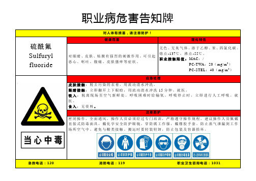
职业病危害告知牌对人体有损害,请注意防护!
硫酰氟Sulfuryl fluoride
健康危害理化特性
对眼睛、皮肤、粘膜有强烈的刺激作用。
可引起
恶心、呕吐、腹痛、皮肤搔痒等症状。
无色、无臭气体。
溶于乙醇、苯、四氯化碳。
熔点-137℃,沸点-55℃。
职业接触限值:MAC:/
PC-TWA:20(mg/m3)
PC-STEL:40(mg/m3)
应急处理
皮肤接触:脱去污染的衣着,用流动清水冲洗。
眼睛接触:立即翻开上下眼睑,用流动清水冲洗15分钟。
就医。
吸入:脱离现场至空气新鲜处。
呼吸困难时给输氧。
呼吸停止时,立即进行人工呼吸。
就医。
食入:无资料。
注意防护
密闭操作,全面通风。
操作人员必须经过专门培训,严格遵守操作规程。
建议操作人员佩戴直接式防毒面具,戴化学安全防护眼镜,穿防腐工作服,戴橡胶手套。
防止蒸气泄漏到工作场所空气中。
避免与酸类接触。
搬运时要轻装轻卸,防止包装及容器损坏。
急救电话:120 消防电话:119 职业卫生咨询电话:1031。
乙酸钡-危险化学品安全标签
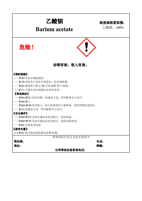
乙酸钡Barium acetate 浓度或浓度范围:乙酸钡:100%
危险!
吞咽有害。
吸入有害。
【预防措施】
——P264作业后彻底清洗。
——P270使用本产品时不要进食、饮水或吸烟。
——P261避免吸入粉尘/烟/气体/烟雾/蒸气/喷雾。
——P271只能在室外或通风良好处使用。
【事故响应】
——P301+P312如误吞咽:如感觉不适,呼叫解毒中心/医生
——P330漱口。
——P304+P340如误吸入:将人转移到空气新鲜处,保持呼吸舒适体位。
——P312如感觉不适,呼叫解毒中心/医生
【安全储存】
——P403+P235存放在通风良好的地方。
保持低温。
——P403+P233存放在通风良好的地方。
保持容器密闭。
——P405存放处须加锁。
【废弃处置】
——P501按当地法规处置内装物/容器。
请参阅化学品安全技术说明书
供应商:电话:地址:邮编:
化学事故应急咨询电话:。
露保细盐安全技术说明书
安全技术说明书页: 1/11 巴斯夫安全技术说明书按照GB/T 16483编制日期 / 本次修订: 06.02.2023版本: 9.0日期/上次修订: 06.09.2021上次版本: 8.1日期 / 首次编制: 29.11.2005产品: 露保细盐Product: Luprosil® Salt(30041137/SDS_GEN_CN/ZH)印刷日期 06.11.20231. 化学品及企业标识露保细盐Luprosil® Salt推荐用途和限制用途: 饲料添加剂公司:巴斯夫(中国)有限公司中国上海浦东江心沙路300号邮政编码 200137电话: +86 21 20391000传真号: +86 21 20394800E-mail地址: **********************紧急联络信息:巴斯夫紧急热线中心(中国)+86 21 5861-1199巴斯夫紧急热线中心(国际):电话: +49 180 2273-112Company:BASF (China) Co., Ltd.300 Jiang Xin Sha RoadPu Dong Shanghai 200137, CHINA Telephone: +86 21 20391000Telefax number: +86 21 20394800E-mail address: ********************** Emergency information:Emergency Call Center (China):+86 21 5861-1199International emergency number: Telephone: +49 180 2273-1122. 危险性概述纯物质和混合物的分类:巴斯夫安全技术说明书日期 / 本次修订: 06.02.2023版本: 9.0产品: 露保细盐Product: Luprosil® Salt(30041137/SDS_GEN_CN/ZH)印刷日期 06.11.2023 标签要素和警示性说明:警示词:危险危险性说明:H318造成严重眼损伤。
Zhengzhou Winsen Electronics Technology Co., LTD 烟

Smoke Gas Sensor(Model:MP-2)ManualVersion: 1.2Valid from: 2017-05-10Zhengzhou Winsen Electronics Technology Co., LtdStatementThis manual copyright belongs to Zhengzhou Winsen Electronics Technology Co., LTD. Without the written permission, any part of this manual shall not be copied, translated, stored in database or retrieval system, also can’t spread through electronic, copying, record ways.Thanks for purchasing our product. In order to let customers use it better and reduce the faults caused by misuse, please read the manual carefully and operate it correctly in accordance with the instructions. If users disobey the terms or remove, disassemble, change the components inside of the sensor, we shall not be responsible for the loss.The specific such as color, appearance, sizes &etc, please in kind prevail.We are devoting ourselves to products development and technical innovation, so we reserve the right to improve the products without notice. Please confirm it is the valid version before using this manual. At the same time, users’ comments on optimized using way are welcome.Please keep the manual properly, in order to get help if you have questions during the usage in the future.Zhengzhou Winsen Electronics Technology CO., LTD.MP-2 Smoke Gas SensorMP-2 model with advanced planar construction is comprised of heater and metal oxidesemiconductor material of subminiature Al 2O 3 ceramic plate, fetch out electrode down-lead, encapsulation in metal base and cap. When the target gas exists , t he sensor’s conductivity is more higher along with the gas concentration rising. Please use simple electrocircuit, convert change of conductivity to correspond output signal of gas concentration.Features:* Good sensitivity to LPG, smoke in wide range * Small size * Long lifespan * Low cost *Simple circuitApplicationDomestic smoke leakage alarm, industrial smoke gas alarm and portable smoke detector.Technical ParametersnFig1.MP-2 ConfigurationModel MP-2Sensor Type Flat Surfaced SemiconductorStandard EncapsulationMetal Cap Target Gas C 3H 8, smoke Detection range200~10000ppm C 3H 8Standard Circuit ConditionsLoop Voltage V c ≤10V DC Heater Voltage V H 5V±0.1V AC or DC Load Resistance R L Adjustable Sensor character under standard test conditionsHeater ResistanceR H 105Ω±10Ω (room tem.)Heater consumptionP H ≤240mWSensitivity S Ro(in air)/Rs( in 2000ppm C 3H 8)≥3 Output voltage Vs 2.5V~4.0V (in 2000ppm C 3H 8) Concentration Slope α ≤0.6(R 3000ppm /R 500ppm C 3H 8)Environment ConditionsOperation Temp. Tao -10℃~50℃ Storage Temp.Tas -20℃~70℃ Relative HumidityRHLess than 95%RHO2 concentrationO 221%±1%(can ’t less than 18%)O2 concentration effects sensor ’s performance.Preheat timeNot less than 48 hoursBasic circuitFig2. Test circuitThis circuit shows the basic measuring circuit of sensor. Two voltage should be applied to this sensor, heating voltage (V H) and test voltage (Vc).V H is used for supplying a certain temperature which can be DC or AC. V RL the voltage on the load resistance (R L) which connects to the sensor in series. Vc is supply the test voltage for RL and it must be DC.CharacterizationFig3.Typical Sensitivity CurveThe ordinate is resistance ratio of the sensor (Rs/R0), the abscissa is concentration of gases. Rs means resistance in target gas, R0 means resistance of sensor in clean air. All tests are finished under standard test conditions. Fig4.Typical temperature/humidity characteristicsThe ordinate is resistance ratio of the sensor (Rs/Rso).Rs means resistance of sensor in 2000ppm C3H8 gas under different tem. and humidity. Rso means resistance of the sensor in 2000ppm C3H8 gas under 20℃/65%RH.AirC3H8 CH4 SmokeFig5.Sensing CurveIt shows VRL value when the sensor in C3H8 gas with different concentration. R L=20kΩ, All tests are finished under standard test conditions. Fig6.Response and RecoveryIt shows the V RL changes when the sensor is put in target gas (2000ppm C3H8) and then is take from it to clean air.Cautions1 .Following conditions must be prohibited1.1 Exposed to volatilizable organic silicon steamSensing material will lose sensitivity and never recover if the sensor absorbs organic silicon steam. Sensors must avoid exposing to silicon bond, fixature, silicon latex, putty or plastic contain silicon environment. 1.2 High Corrosive gasIf the sensors are exposed to high concentration corrosive gas (such as H 2S, SO X , Cl 2, HCl etc.), it will not only result in corrosion of sensors structure, also it cause sincere sensitivity attenuation. 1.3 Alkali, Alkali metals salt, halogen pollutionThe sensors performance will be changed badly if sensors be sprayed polluted by alkali metals salt especially brine, or be exposed to halogen such as fluorine.1.4 Touch waterSensitivity of the sensors will be reduced when spattered or dipped in water.1.5 FreezingDo avoid icing on sensor’s surface, otherwise sensing material will be broken and lost sensitivity. 1.6 Applied higher voltageApplied voltage on sensor should not be higher than stipulated value, even if the sensor is not physically damaged or broken, it causes down-line or heater damaged, and bring on sensors’ sensitivity characteristic changed badly. 1.7 Voltage on wrong pinsAs Fig8,Pin 1&2 connects to heater circuit, Pin 3&4 connects to measuring circuit; Under the requested conditions, heating and measuring can use the same power circuit. NOTE: the two pins near the protuberance mark is heating electrode.Fig6.Pin Schematic Diagram2 .Following conditions should be avoided 2.1 Water CondensationIndoor conditions, slight water condensation will influence sensors’ performance lightly. However, if watercondensation on sensors surface and keep a certain period, sensors ’ sensitiv e will be decreased. 2.2 Used in high gas concentrationNo matter the sensor is electrified or not, if it is placed in high gas concentration for long time, sensors characteristic will be affected. If lighter gas sprays the sensor,it will cause extremely damage.ProtuberancePin 1&2 is heating electrode, Pin 3&4 is measuring electrode.The sensors resistance will drift reversibly if it’s stored for long time without electrify, this drift is related with storage conditions. Sensors should be stored in airproof bag without volatile silicon compound. For the sensors with long time storage but no electrify, they need long galvanical aging time for stability before using. The suggested aging time as follow:Stable2.No matter the sensors electrified or not, if exposed to adverse environment for long time, such as high humidity, high temperature, or high pollution etc., it will influence the sensors’ performance badly.2.5 VibrationContinual vibration will result in sensors down-lead response then break. In transportation or assembling line, pneumatic screwdriver/ultrasonic welding machine can lead this vibration.2.6 ConcussionIf sensors meet strong concussion, it may lead its lead wire disconnected.2.7 Usage Conditions2.7.1For sensor, handmade welding is optimal way. The welding conditions as follow:⚫Soldering flux: Rosin soldering flux contains least chlorine⚫homothermal soldering iron⚫Temperature:250℃⚫Time:less than 3 seconds2.7.2If users choose wave-soldering, the following conditions should be obey:⚫Soldering flux: Rosin soldering flux contains least chlorine⚫Speed: 1-2 Meter/ Minute⚫Warm-up temperature:100±20℃⚫Welding temperature:250±10℃⚫One time pass wave crest welding machineIf disobey the above using terms, sensors sensitivity will be reduced.。
Victaulic V2725与V2726自动撒水头 说明书

技术规格型号:V2725、V2726类型:传统型公称孔口尺寸:1/2”/13 mmK系数:5.6 Imp./8.1 S.I.^公称螺纹尺寸:1/2” NPT/15 mm最大工作压力:175 psi/1200 kPa工厂水压试验:100% @ 500 psi/3450 kPa最小操作压力:7 psi/48 kPa温度等级:请参见第2页上的图表材料规格溅水盘:UNS C51000青铜球:玻璃,内装丙三醇溶液球的公称直径:• 标准型:5.0 mm• 快速反应型:3.0 mm加载弹簧:UNS C65100硅青铜封帽:UNS C65100硅青铜密封:聚四氟乙烯(Teflon)*胶带弹簧:钡镍合金框架:钢模铸造黄铜65-30定位弹簧:UNS S30200不锈钢附件安装扳手: • 开口扳手:V27、V38-3喷淋头表面状态:• 原色黄铜• 镀铬• 腊涂†**• 涂白漆RAL 9010**• 涂铅• 专利镍-特富龙*†** 涂层有关存放柜及其它附件,请参阅另附资料。
^ 对于K系数,当压力单位为bar时, 将S.I.单位乘10.0。
* Teflon (特富龙)为杜邦公司注册商标。
† 非VdS认证产品 。
** 耐腐蚀性能还取得了UL列表认证。
本V27型传统老式喷淋头设计用于形成半球喷洒模型,这种模型将大约一半水雾向上折向天花,另一半向下喷洒,它既可按上喷方位安装,也可以下喷方位安装。
可配备标准或快速反应玻璃球供货。
设计中更融入了反映最新技术水平的热敏易碎玻璃球(标准及快速反应型),以确保动作快速、准确。
钢模铸造框架外形比传统砂模铸造框架更为流畅、更吸引人。
它铸有一个六角形扳手凸起段,使得不同角度上紧都极为方便,从而减少了装配麻烦。
本喷淋头按不同温度等级(见第2页图表)及表面状况供货,以满足不同的设计需要。
喷淋头工作原理工作机构是一内装热敏液体的易碎玻璃球。
火灾发生后,环境温度上升,引起球内液体膨胀。
当环境温度达到喷淋头整定温度时,球即破碎。
- 1、下载文档前请自行甄别文档内容的完整性,平台不提供额外的编辑、内容补充、找答案等附加服务。
- 2、"仅部分预览"的文档,不可在线预览部分如存在完整性等问题,可反馈申请退款(可完整预览的文档不适用该条件!)。
- 3、如文档侵犯您的权益,请联系客服反馈,我们会尽快为您处理(人工客服工作时间:9:00-18:30)。
高效节能
技术创新
舒适宁静
2
环保与责任
机组特点
高效节能
YSPA系列风冷螺杆式热泵机组使大幅节省能源费用变得非常简单,结合全面的创 新设计,如高效螺杆压缩机、独立中压罐等,制冷最高效率可达3.57,制热最高 效率可达3.55,与传统风冷热泵机组相比节省费用可达15%。前所未有的超高效率 将帮助您大幅缩短项目回报期。
制冷量
kW 400
516
623
785
915
1032
1139
1246
1301
1408
1570
制热量
kW 384
512
588
764
896
1025
1101
1177
1276
1352
1528
压缩机 输入功率
制冷 制热
kW 98
130
156
191
228
260
287
313
321
kW 91
124义工况参数表 - 标准型机组
型号
标准型 0520SE 0630SE 0770SE 1050SE 1150SE 1260SE 1300SE
1400SE
制冷量
kW
497
618
773
993
1114
1236
1269
制热量
kW
471
574
748
941
1045
1148
1219
压缩机 输入功率
制冷 制热
kW
技术创新
YSPA系列风冷螺杆式热泵机组集中了多种创新技术,如专利设计的中压罐、分步 除霜系统和活塞式四通换向阀等,有效避免了传统风冷热泵机组的吸气带液、除 霜不彻底、四通换向阀卡死等现象,充分保证YSPA的高效性、稳定性和可靠性。 独特的智能除霜控制逻辑,自动选择除霜切入/退出时间节点,有效避免频繁除霜 和超时除霜,同时结合先进的错时除霜设计,大幅减小除霜时热水水温波动;换 热器底部采用半边支撑,无水槽和加热带,充分防止冰裙和爬冰;专利设计的X 形结构可防止盘管底部冰冻,加快机组的除霜速度,在寒冷的冬天给您带来舒适 的空调环境。
运输重量 运行重量
kg
5002
5928
6801
8548
10930 11856 12729 13602 14476
15349 17096
(5002+5928) (2x5928) (5928+6801) (2x6801) (5928+8548) (6801+8548) (2x8548)
kg 5302 6228 7101 8848 11530 12456 13329 14202 15076 15949 17696
YSPA热回收机组特点
1. 充分利用能源,在制冷的同时可以提供“免费”热水, 能有效减少废热的排放,有利于环境保护、减少资源浪费和节省运行费用; 2. 一机多用,可实现夏季制冷、冬季供暖、制取生活或工艺热水等多种功能; 3. 可提供全热回收或部分热回收两种选项,多种组合,灵活多变,适应不同场合; 4. 热回收率同行业领先,最高热水温度可达55 ℃; 5. 与传统锅炉系统相比,热回收系统更加高效环保,且热回收机组不过多占用安装场地,可以省掉锅炉设备的初投资及锅炉房的建筑面积。
螺杆式压缩机
热回收换热器 热回收出水 热回收进水
三通阀
四通阀
风冷式换热器 (冷凝器)
壳管式换热器 (蒸发器)
冷冻水出水 冷冻水进水
电子膨胀阀
YSPA热回收原理示意图(机组制冷模式)
5
名义工况参数表 - 高效型机组
型号
高效型 0405HE 0525HE 0635HE 0775HE 0930HE 1060HE 1160HE 1270HE 1310HE 1410HE 1550HE
275
302
310
348
383
337
374
冷媒
R134a
冷媒回路
PCS 1
2
2
2
3
4
4
4
4
4
4
类型
半封闭螺杆
压缩机
数量
PCS 1
1
1
1
2
2
2
2
2
2
2
最小负荷
25% 25% 25% 25% 12.5% 12.5% 12.5% 12.5% 12.5% 12.5% 12.5%
类型
壳管式
水流量
l/s
19.1
舒适宁静
YSPA系列风冷螺杆式热泵机组提供了丰富的降噪选项,结合标准的V型盘管设 计,带来超低噪音的运行;宁静的夜间运行模式能保证机组在夜晚也达到您的静 音要求。
环保与责任
环保制冷剂R134a,对大气臭氧层没有任何破坏作用,在全球无淘汰期限。 高效运行减少电能消耗,间接地减少电厂CO2的排放量。
命名方法
电机 — 全封闭鼠笼式三相异步电动机直接驱动,电机内置热敏电 阻过热保护元件,保证运行安全可靠;电机防护等级IP55,绝缘等 级F级,并配备有双重密封和永久润滑功能的轴承。
电子膨胀阀
YSPA系列机组使用了先进的电子膨胀阀,精确控制进入蒸发器的 制冷剂流量,保证变工况下的机组效率。电子膨胀阀通过二极步进 电机控制节流孔开度,该电机为双相双极电机,不通电时阀开度不 变,当电脉冲送到任一方的电机绕组时,在电刷上就产生一个作用 力来驱动电子膨胀阀。阀开闭方向和幅度取决于传递过来的电脉冲 的相位关系和大小。
130
162
204
260
291
323
334
kW
122
144
188
245
267
289
310
冷媒
R134a
冷媒回路
PCS
1
2
2
4
4
4
4
类型
半封闭螺杆
压缩机
数量
PCS
1
1
1
2
2
2
2
最小负荷
25%
25%
25% 12.5%
12.5%
12.5%
12.5%
类型
壳管式
水流量
l/s
23.8
29.6
37
47.5
53.3
远程控制器 (可选件)
4
热回收
热回收系统介绍
随着科技水平迅速发展以及人类文明程度不断提高,人们对生活、环境的舒适度提出了更高的要求,伴随而来对于能源的需求也急剧增 大。现代空调产品为人们的生活提供了满意的舒适度,与此同时也在大量消耗着宝贵的能源。因此,节能环保成为了我们设计和开发新产品 的重要理念及持之以恒追求的目标。
24.7
29.8
37.6
43.8
49.4
54.5
59.6
62.2
67.4
75.1
水侧换热器
水压降
kPa 46.8
74.6
83.7
70.2
74.8
74.5
82.9
83.7
74.7
82.7
70.1
接管类型
法兰
接管尺寸
DN 250
250
250
250 250X2 250X2 250×2 250×2 250×2 250×2 250×2
冷凝器
转子-转子置于高精度的铸铁压缩机气缸中,获得了最佳的运动空 间。阴阳转子可实现无磨损的长久可靠运行,这也正是螺杆压缩机 的一大优点。
机体-铸铁的压缩机机体加工精密,提供了最佳余隙和最好的效率。
减震-每台压缩机都是安装在减震垫上以减少传递到基础结构上的 震动。
控制系统
所有的控制和启动设备在工厂安装好并经过功能测试。控制柜包 括电源、控制中心和控制元件,装于一个镀锌钢板制成的箱体 内,由电机启动器和机组控制器两个独立的部分组成。控制柜装 有铰链门,箱体设计符合IP55防雨防尘标准,表面喷涂成约克标准 香槟色。
电气数据
最大运行电流 A
320
413
494
616 320/413 413/413 413/494 494/494 413/616 494/616 616/616
启动电流
A
443
743
875
888 443/743 743/743 743/875 875/875 743/888 875/888 888/888
YSPA系列 风冷螺杆式热泵机组
约克YSPA系列风冷螺杆式热泵机组是专为中央空调的末端设备提供冷 (热)水源的空调主机设备。机组为整体式设计,可安装于室外屋顶或地 面上。机组能够实现夏季制冷、冬季供暖及热回收等多种功能,可广泛应 用于商场、办公楼、宾馆、医院等不同场合。
YSPA机组采用R134a环保制冷剂,其高效系列机组能效比最高可达3.57, 远高于国家一级能效指标,成为世界上同类产品中最高效节能的风冷热泵 机组。
运行状况显示 运行数据-包括系统的冷冻水出水温度、环境温度、蒸发压力、排 气压力、排气温度、润滑油压力和压缩机电流等。
盘管 — V型盘管设计,由高效内螺纹铜管和亲水铝箔翅片经过机械 胀管紧密结合而成,传热效果更好,风速分布均匀,不易结霜。
风机 — 包括耐蚀的铝轴毂和低噪音复合材料的叶片。其设计满足 无振动运行的最大效率以及静态和动态平衡。每个风机由单独的电 机直接驱动,并安装在空气能够自由流通的位置。风扇罩由高强 度、带防锈层钢板制作而成。
注: 1. 制冷工况:冷冻水进出水温度12/7℃,水侧换热器污垢系数0.018m2.K/kW,室外环境温度35℃,电源电压:380V/3Ph/50Hz; 2. 制热工况:热水出水温度45℃,水侧换热器污垢系数0.018m2.K/kW,室外干球温度7℃,湿球温度6℃,电源电压:380V/3Ph/50Hz; 3. YSPA0930HE, YSPA1060HE, 1160HE, 1270HE, 1310HE, 1410HE, 1550HE: 可在深度方向或宽度方向连接; 4. YSPA0930HE, YSPA1060HE, 1160HE, 1270HE, 1310HE, 1410HE, 1550HE: 在运输过程中分两段式运输。