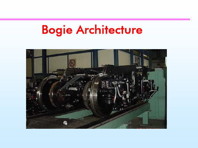
英汉对照-不同结构的径向转向架与普通转向架之理论比较_英文
货车转向架—副构架式径向转向架(车辆构造检修课件)
转K7 背景:
重载(2E) 特点:
径向(自导向) 时间:
2007 厂家: 眉山车辆厂
七、径向转向架
七、径向转向架(Radial Bogie )
1.矛盾
蛇形运动稳定性 曲线通过性能 对轴箱定位刚度有相是解决上述矛盾的最有效措施之一: 1.保证足够的直线运动稳定性 2.径向转向架利用进入曲线时轮轨间蠕滑力,通过导向机构的 作用使轮对“自动”进入曲线的径向位置。
摇枕组成
摇枕为B+级钢铸造。摇枕结构与现有三大件转向架的摇枕结 构基本相似,摇枕两侧开有4个对称的方孔,用以连接杆的安装。 下心盘直径为375mm心盘。摇枕组成由摇枕、下心盘、斜面磨耗 板、固定杠杆支点座等零部件组成。
侧架组成
侧架为B+级钢铸造。侧架中央铸有弹簧托盘,以保证承载弹 簧组、变摩擦减振器的安装,取消了传统三大件转向架侧架两端 处的导框结构,而设计为方形平台,便于安装橡胶堆。
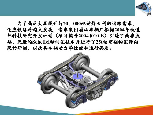
为了满足大秦线开行20,000吨运煤专列的运输需求, 适应铁路跨越式发展,南车集团眉山车辆厂根据2004年铁道 部科技研究开发计划(项目编号2004J010-B)引进了南非成 熟、先进的Scheffel转向架技术并进行了25t轴重副构架转向 架的研制,以改善车辆动力学性能和运行品质。
七、径向转向架
七、径向转向架
3.典型径向转向架
与K6的区别
轮对径向装置 交叉支撑装置;
两组橡胶堆
轴箱橡胶垫;
基础制动装置—下拉杆 中拉杆;
空重车调整—接触班(副构架)
横跨梁。
七、径向转向架
3.典型径向转向架
橡胶堆
橡胶堆由金属和橡胶硫化而成,橡胶堆为矩形结构,顶板上 有两个定位销,底板上有两个定位销,定位销直径均为30mm。 在组装时,导电铜绞线靠近侧架内侧。橡胶堆的纵向和横向刚度 是不相同的,组装时有人字形的沿车轴中心线,即横向方向。
综述转向架的不同分类方式及各自的原理
1、关于转向架的分类,有很多种形式。
由于车辆用途运行条件差异,制造维修方法的制约和经济条件等具体因素的影响,对转向架的性能结构参数和采用的材料及工艺等要求就要差别,因而出现了多种形式的转向架。
有按轴数分类,有按轴向定位方式分类,有按有无摇枕分类。
各自转向架的主要区别在于:弹簧悬挂装置的结构和参数,垂向载荷的传递方式,轴向定位方式,制动装置的类型和安装,构架的结构形式以及作用原理等方面。
因此,转向架可按其作用原理及结构形式分类。
(1)轴数与类型车辆所用的轴型基本上可分为B、C、D、E、F、G六种。
轴直径越粗,容许轴重越大,但是大容许轴重要受线路和桥梁的强度标准的限制,一般货车采用B、D、E、F、G五种轴型,客车采用C、D两种轴型,随着我国铁路的发展,其趋势是发展重载和快速运输,因此新型货车主要运用E型轴,新型客车主要运用D型轴按轴数分类,转向架有二轴、三轴和多轴,转向架的轴数一般根据车辆总重和每根车轴容许的轴重确定,我国大多数客货车采用二轴转向架,一些大吨位货车及公务车等采用三轴转向架,在长大重载货车上用多轴转向架或转向架群。
(2)按轴向定位方式①固定定位:轴箱与转向架铸成一体,或是轴箱与侧架用螺栓及其他紧固件连接成为一个整体,使得轴箱和侧架之间不能任何相对运动。
②导框式定位:轴向上有导槽,构架上有导框,构架的导框插入轴箱的导槽内,这种结构可以容许轴箱与构架之间沿着在垂向有较大的相对位移,但在前后、左右方向仅能在容许的范围内,有相对较小的位移。
③干摩擦导柱式定位:安装在构架上的导柱及坐落在轴向弹簧托板上的支持环均装有磨耗套,导柱插入支持环,发生上下运动,两磨耗套之间是干摩擦。
它的作用原理是轴箱橡胶垫产生不同方向的剪切变形,实现弹性定位作用。
④油导筒式定位:把安装在构架上的轴箱导柱和坐落在轴向弹簧托板上的导筒分别做成油缸和活塞的形式,导柱插入导筒,导柱上下移动时,油液可进出导柱的内腔,产生减振作用,它的作用原理是,当构架与轴箱之间产生水平方向的相对运动时,利用导柱与导筒传递纵向力和横向力,再通过轴箱橡胶垫传递轴箱体,使橡胶垫产生不同方向剪切变形,实现弹性定位作用。
转向架的名词解释
转向架的名词解释转向架是指装在轮胎上并能使机动车辆改变行进方向的重要部件。
它主要由结构牢固的车桥、悬挂装置和转向器组成。
在现代交通工具中,转向架的设计及性能直接影响到车辆的操控性、稳定性以及行进安全性。
一、转向架的基本结构和组成转向架通常由车桥、悬挂装置和转向器三大部分组成,每个部分都发挥着重要的作用。
1. 车桥:车桥是转向架的主要支撑结构,它连接着轮胎和车辆的其他部分。
车桥的选材和制造工艺直接关系到转向架的强度和耐用性。
经过不断的发展和创新,现代转向架的车桥多采用高强度钢材,甚至是复合材料制成,以提高整体的强度和稳固性。
2. 悬挂装置:悬挂装置位于车桥和车身之间,起着减震和支撑作用。
它通过减缓来自不平路面的冲击,降低车辆的颠簸感,并保持车轮与地面的接触,提供更好的操控和行驶稳定性。
常见的悬挂形式有独立悬挂、半独立悬挂和非独立悬挂等,不同类型的悬挂装置适用于不同的车辆和行驶条件。
3. 转向器:转向器是转向架中最核心的部件,它负责将驾驶员的转向指令转化为车轮的转向动作。
常见的转向器包括齿轮传动、液压传动和电力传动等。
在现代汽车中,电力助力转向系统逐渐替代了传统的机械和液压转向系统,使驾驶更加轻松和舒适。
二、转向架的作用和意义转向架作为汽车、飞机、火车等交通工具的重要组成部分,扮演着至关重要的角色。
1. 改变行进方向:转向架通过转动车轮,使车辆在行进过程中能够改变方向。
它可以使车辆实现左转、右转、掉头等动作,实现自由灵活的行驶。
2. 提供操控性和稳定性:转向架的设计和性能直接影响到车辆的操控性和稳定性。
合理的转向架设计能够使车辆操控更加准确、响应更加迅速,提高驾驶员的操作感受和行驶安全性。
3. 减少轮胎磨损:良好的转向架能够使轮胎与地面的接触更均匀,减少轮胎的磨损和磨损不均,延长轮胎的使用寿命。
同时,转向架也能够减少轮胎的滑动和打滑,提供更好的牵引力和较短的制动距离。
4. 提高行驶安全性:转向架的稳定性和灵活度直接影响到车辆的行驶安全性。
转向架的基本结构

转向架的基本结构转向架是飞机的重要组成部分之一,主要用于改变飞机的飞行方向。
它由多个部件组成,包括转向轮、转向杆、齿轮箱、液压系统等。
1.转向轮:转向轮是转向架的核心部件之一、它通常由橡胶制成,具有良好的抗磨损和抗冲击性能。
转向轮安装在转向架的前部,通过转轴与转向杆连接。
转向轮可以根据驾驶员的操作控制转向架的转向角度。
2.转向杆:转向杆位于飞机的驾驶舱内,用于操纵转向架的转动。
驾驶员可以通过转向杆的左右操作控制转向架的转向方向。
转向杆一般由金属材料制成,具有足够的强度和刚度,以承受飞行中的各种力和振动。
3.齿轮箱:齿轮箱是转向架中的一个重要部件,主要用于传递转向力和承受飞行过程中的各种负载。
齿轮箱内部装有一组齿轮,通过齿轮传动的方式将转向轮的旋转转化为转向力。
齿轮箱一般由高强度金属材料制成,具有耐磨耐用的特点。
4.液压系统:液压系统是转向架中的关键组成部分,用于提供所需的液压能量以控制转向架的运动。
液压系统由液压泵、液压油箱、液压阀门等组成。
液压泵将液压油从油箱中抽出,并通过液压阀门控制液压油的流向,从而实现对转向架的控制。
5.传感器和控制系统:为了确保飞机的安全和稳定,转向架通常还配备有多个传感器和控制系统。
传感器用于监测转向架的转动状态和转向角度,并将这些信息传递给控制系统。
控制系统则根据传感器的数据,对转向架进行相应的控制操作,确保飞机朝着正确的方向飞行。
总结起来,转向架的基本结构包括转向轮、转向杆、齿轮箱、液压系统、传感器和控制系统等多个组成部分。
这些部件紧密配合,通过驾驶员的操控和液压系统的控制,实现对飞机飞行方向的改变。
转向架的设计必须具有足够的强度和刚度,以应对飞行中的各种负载和振动,同时还要保证灵活性和敏感性,以提供准确的转向控制,确保飞机安全稳定地飞行。
不同结构的径向转向架与普通转向架之理论比较
The r tc l Co p r s n Be we n Di f r n nf g r t O f o e i a m a i o t e f e e t CO i u a i ns O Ra a nd Co e i na gi s di la nv nto lBo e
的分 析 。 基 于 不 同 的 战略 目的 , 些 析 以 促 使 具 有 导 向 这
J F. . GARCI ,t . ( p i A e c S an)
Ab t a t s r c :Th s a t l o i r i e c mp r s t e d n mi e a i u fd fe e t c n i u a in f r d a n o v n c a e h y a c b h v o r o if r n o fg r to s o a i la d c n e - to a wo a l o is i n l t — x e b g e .Th n l s s h s b e o c n r t d o a a t r u h a t b l y,l t r l wh e— e a a y i a e n c n e t a e n p r me e s s c s s a i t i a e a e l t a k f r e n c r e a d wh e a n ie .Th e u t h w h tt e r d a o i o f u a i n t d e o r c o c si u v n e l we ri d c s e r s lss o t a h a i l ge c n i r to ss u id d b g n tma e sg i c n o t i u i n e e a p l a i n t e a d t o v n i n l o i .I so l n e o k i n f a tc n rb to s i g n r l p i t s wih r g r o a c n e t a g e t n y u d r i n a c o o b i s e ii u n n o d to s a d t p so e v c h ts me r d a o i o fg r to s p o i e a v n a e t p cf r n i g c n ii n n y e fs r i e t a o a ilb g e c n i u a i n r v d d a t g s wih c r s e t t h o v n i n lb ge e p c o t e c n e to a o i . Ke r s:r d a o i ;c n i u a i n;c m p r y wo d a i lb g e o fg r to o ae
转向架的性能参数
转向架的性能参数转向架是列车的一个重要组成部分,它承载着整个车辆的重量,并负责将车辆引导到正确的线路上。
转向架的性能参数对列车的运行安全性、稳定性和舒适性具有重要影响。
以下是一些常见的转向架性能参数:1.构架:构架是转向架的基础结构,它负责支撑和连接各个零部件。
构架的强度、刚度和重量直接影响到转向架的性能。
2.轮对:轮对是由车轮和车轴组成的。
它的作用是承受车辆的重量,并提供牵引力和制动力。
轮对的直径、接触面和轮箍材料等都会影响到车辆的运行性能。
3.悬挂系统:悬挂系统是连接构架和轮对之间的缓冲装置,它可以减少车辆运行时的冲击和振动,提高乘坐舒适性。
悬挂系统的刚度和阻尼系数需要根据车辆的运行速度和载重量进行选择和设计。
4.驱动装置:驱动装置是提供牵引力的装置。
它包括电动机、齿轮箱、联轴器和车轮等部件。
电动机的功率、转速和扭矩等参数需要与齿轮箱和车轮匹配,以达到最佳的牵引效果。
5.制动装置:制动装置是使车辆减速或停止的装置。
它包括制动盘、制动缸、制动片和制动手柄等部件。
制动装置的性能需要与车辆的重量、速度和运行条件相匹配,以确保安全性和可靠性。
6.轴重和载重:轴重是指每个轮对所承受的重量,而载重则是指车辆的总重量。
这些参数对车辆的运行性能和稳定性具有重要影响。
7.运行速度和加速度:运行速度是指车辆在轨道上行驶的速度,而加速度则是指速度的变化率。
这些参数对车辆的运行效率和乘客的舒适性具有重要影响。
8.曲线通过能力:曲线通过能力是指车辆在曲线轨道上行驶的能力。
这涉及到车辆的悬挂系统、车轮和齿轮箱等部件的匹配和设计。
9.运行稳定性:运行稳定性是指车辆在轨道上保持稳定的能力,特别是在高速行驶时。
这需要考虑到悬挂系统、车轮和轨道条件等因素。
10.维护和检修:维护和检修是保证转向架性能的重要措施。
需要定期检查和更换零部件,保持转向架的良好状态。
同时,也需要针对不同的运行条件和载荷进行适当维护和调整。
铁道机车专业英语词汇-转向架

侧架 摇枕 心盘 旁承 轴箱 第二系悬挂装置 螺旋弹簧 弹簧拖板
brake lever [ˈlevər] n.杠杆
制动杠杆
brake hanger [ˈhæŋɚ] n.衣架;挂钩
制动梁吊
brake beam [bim] n.束;梁
制动梁
bottom conducting[kənˈdʌkt] v.传导;引导;控制rod [rɑ:d] n.杆,拉杆
两个轮子固定在一个直轴上,这样两个轮子就可以同时转动。 这叫做轮对。
P039 倒数二段
翻译
转向架的两个侧架靠在轴承轴箱上,并通过簧板和螺旋弹簧支撑 摇枕的两端。
suspension (secondary suspension)
To absorb shocks between the bogie and the rail vehicle body. Common types are coil springs.
轴箱悬挂通常由转向架构架和车轴轴承之间的弹簧组成,允许上 下移动。滑动用以防止横向移动。
Two wheels are affixed[əˈfɪks]使固定 to a straight axle so that both wheels rotate[ˈroʊteɪt]旋转 in unison[ˈjunɪsən] n. 和谐;一致. This is called a wheelset轮对.
径向转向架
客车径向转向架发展相对于货车径向转向架较为落后,其主 要原因:
• 客车轴重较小和具有两系悬挂,其相应的磨耗要小于货车;
• 早期世界上客车的保有量不足货车的10%,故长时间未能引起
足够的重视;
• 早期列车速度普遍较低。
径向转向架的分类
自导向径向转向架(Scheffel径向转向架) 迫导向径向转向架(Devine-Scala径向转向架)
自导向径向转向架(Scheffel径向转向架)
迫导向径向转向架(Devine-Scala径向转向架)
采用焊接刚性构架和迫导向的模式,通过导向杠杆系统将车 体和转向架间的回转角度传给轮对,使轮对在曲线上能趋于径向 位置。——外力
• 主动迫导向——计算机系统 (液压缸的杠杆长度) • 被动迫导向——导向机构 (车体与转向架的相对位移)
• 源自早期货车
自导向径向转向架(Scheffel径向转向架)
相互 Байду номын сангаас合
通过导向臂及限力装置将同一转向架的前后轮对相连,在提 高转向架抗菱刚度同时还增加了轮对自导向径向调节作用。
通过径向调节机构解除对 轮对的摇头约束 ,利用轮 轨间的蠕滑导向力矩带动 径向调节机构转动 ,使转 向架的轮对取得径向位置。
采用径向转向架,列车在通过曲线时,能够保证车轮与钢轨
紧密接触,为列车提供足够的黏着力,使得牵引力不会降低。
图1 普通转向架与径向转向架通过曲线的情况
普通转向架:钢轨和轮缘磨耗加剧,限制列车曲线通过速度,增加机车动 力消耗,线路和机车车辆的维修量增加,影响行车安全;轮轨间横向作用 力大。——不适于重载、高速发展
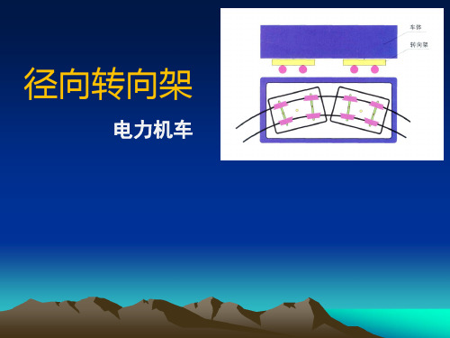
径向转向架
电力机车
概述
转向架——动
车辆动力学性能 主要取决于转向架的悬挂参数,其主要包括曲线通过性能和直线 上的横向稳定性,但二者对转向架悬挂参数的要求通常是相互矛盾的。
国外转向架
国外高新技术转向架的现状姓名:张强班级:机械1206【摘要】:SwingMotion货车转向架在两侧架之间增设一弹簧托板,在弹簧托板和侧架之间装有带弧面的摆块,在侧架和承载鞍之间也以弧面连接,侧架和弹簧托板组成一个类似客车转向架摇动台的结构,侧架相对于摇枕可以横向摆动,大大减少了转向架的横向刚度,最大摆动角度可达3°。
【关键词】:SwingMotion货车转向架、Scheffel自导向径向转向架、DB—661型转向架、DRRS型转向架、TF25型转向架向架、RESCO 侧架迫导向货车转向架美国SwingMotion货车转向架(1)在两侧架之间增设一弹簧托板,在弹簧托板和侧架之间装有带弧面的摆块,在侧架和承载鞍之间也以弧面连接,侧架和弹簧托板组成一个类似客车转向架摇动台的结构,侧架相对于摇枕可以横向摆动,大大减少了转向架的横向刚度,最大摆动角度可达3°。
(2)取消了摇枕挡,在摇枕和弹簧托板间增设横向挡,横向挡的高度比摇枕挡的高度低,这样,当车体受到侧向力作用时,由侧向力引起的车辆倾覆力矩和车轮减载显著下降,提高了车辆的运行安全性。
SwingMotion转向架可大大提高运行速度,最高运行速度可达160km/h。
由于加大了悬挂的横向柔度,能有效地改善车辆横向运行平稳性和运行安全性。
但SwingMotion转向架受到三大件式转向架结构的限制,质量大,结构复杂,磨耗件较多,加大了维修工作量和维修成本,且基础制动装置仍只能采用单侧踏面制动,对于制动距离要求较高的国家和地区是不适用的。
目前,SwingMotion转向架用于美国和加拿大等北美国家的快运集装箱平车和公铁两用车上。
南非Scheffel自导向径向转向架。
Scheffel自导向转向架是在传统三大件式转向架的基础上,用1根弓形梁将每条轮对的左右两侧联系在一起,组成一个副构架,再用2根对角斜撑连杆将前后副构架联系在一起,形成自导向机构。
简述转向架的结构组成
简述转向架的结构组成
转向架(Bogie),俗称"车轴",是轨道交通车辆中的重要部件,用于支撑车辆底盘和提供转向、减震等功能。
转向架是组成轮轴传动系统的主要构件,结构复杂、功能齐全。
下面将生动全面地介绍转向架的结构组成。
1. 转向架框架
转向架的框架是由钢板焊接而成,主要用于支撑整个转向架的各个部件。
转向架框架中间通常设有托架孔、制动器安装孔,便于对其他装置进行安装调整。
2. 弹簧装置
转向架上的弹簧装置主要用于缓冲车辆的振动和冲击,使乘车更加平稳舒适。
常见的弹簧装置有叶片弹簧、气弹簧等。
3. 转向机构
转向架的转向机构是主要的转向装置,其结构复杂,包含多个部件组成。
转向机构主要包括转向齿轮、转向轮、转向台、轴承等。
4. 轮轴
轮轴是转动轮子的核心组件,也是转向架中的关键部件。
轮轴的结构包括闸带轮、保持轮、轴承座等。
5. 制动装置
制动装置是保障列车行驶安全的重要部件,通常安装在转向架上。
制动装置包括制动机构、制动盘、制动爪等。
以上就是转向架的结构组成,它们协同作用,构成了转向架这一
重要部件。
了解转向架的结构组成,对于轨道交通业的工程师和技术
人员具有重要的指导意义,能够帮助他们更好地了解和维护车辆。
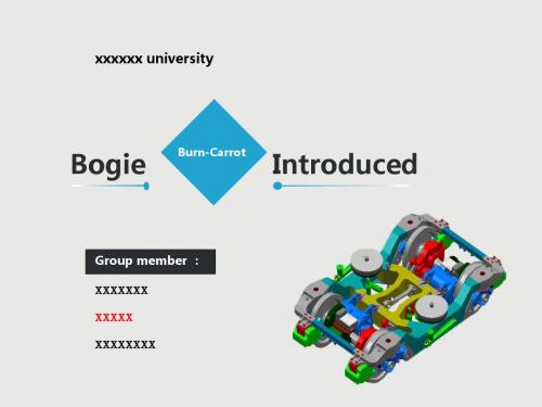
Bogie Introduction 火车转向架介绍
Train set • Axle load: 18.7 t • Tractive force: 21.9 kN • Max. speed: 180 or 200 km/h • Propulsion system weight: 980 kg
Traction motor Gearbox
The axle box consists of a bearing housing with conical roller bearings. All axle boxes are the same. However, their outer cover has different designs to allow the mounting of accessory aparatus such as speed pick-ups, return current devices or brush devices for protectiension
Cornering for rigid and radially-steered bogies respectively
Rigid bogie
Radially-steered bogie
As the wheel sets are mounted on the primary suspension with rubber elements, which allow some movement in all directions, the wheel sets can move radially when cornering (self-regulating radial steering). This function reduces the wear on wheel flanges and track
铁路各专业英语单词整理
铁路各专业单词整理Freight train货运列车Passenger train旅客列车Heavy freight重载货运Sleeping car卧铺车Dining car餐车Run-around track调车线Inter-city train城际列车Local train管内列车,慢车Elctric traction电力牵引Stopper慢车Double-decked passenger train双层旅客列车Locomotive 机车freight wagon货车passenger coach 客车multiple units动车组metro car 地铁车辆light rail轻轨railway service cars 铁路服务车Coach, carriage 客车Motor car (trailer car)动力车(拖车)Container集装箱车Tanker罐车Driving cab司机室TOFC平板拖车Box wagon棚车Monorail单轨Refrigerator wagon冷藏车High-speed railways高速铁路Maglev磁悬浮Open-topped wagon敞顶车Rail铁轨standard gauge标准轨距narrow gauge, broad gauge窄轨,宽轨Trackbed 道床Sleeper 枕木Crosstie 枕木subballast,道砟,底部道砟fastener紧固件Turnout道岔Derail(derailment)脱轨Crossing 平交道口colliery 煤矿quarry 采石场flanged steel wheels 有凸缘钢轮copper ore 铜矿speak of 谈到,提及backbone 骨干bulk freight 散装货物mass commutation traffic 大规模通勤运输short haul 短途运输Merchandise traffic 货物运输Depreciation 减值,折旧,贬值Settling 沉降,沉积bulk freight 散装货物Subgrade 地基,路基Soil stratum 地层Embankment 堤坝Trim off 修剪Organic topsoil 有机表层土ivil engineering 土木工程Earthwork 土方,土方工程Gravity wall 重力墙Drainage 排水系统,排水装置Real estate 房地产,不动产Crane 起重机Tamper 捣固机Trolley 台车,手推车,电车Headway 进展,向目标前进Cog railway嵌齿铁路Rubber-tired underground橡胶轮地铁Siding旁轨,支线Coupler车钩Maintenance of way 道路维护Long-distance train长途列车Channel Tunnel海峡隧道parcel package 包裹Travelling post offices 移动邮局 Centrifugal force 离心力pram 婴儿车Wheelchair 轮椅Conurbation 有卫星城市的大都市elevated structure 高架结构Accelerate (decelerate) 加速(减速)Tram, trolley, streetcar有轨电车 Flexibility 机动,灵活 Low loder 低架拖车Sneak into 偷偷地摸进Stow away 偷乘,搭白车Fatality disasterKit 工具包,装备earn one‘s keep 值得雇用, 挣饭吃Show up 揭露,露出Dead end terminal 闭塞终端 Buffer stop 止冲器 Crossover 转辙轨Locomotive escape 机车折返 Phase out 逐步淘汰,逐步停止Intensive service auxiliary equipment 辅助设备, 备用设备, 附属设备Heavy maintenance 大修Keep at forefront of 保持在……最前沿train loading 列车运载量Train capacity 列车运载能力Density of passengers 乘客密度Load factor 上座率Patronage 保护,光顾,赞助High degree of standardisation 高度标准化pilot end beam Bellmouth 钟形口,喇叭口Line up 整队,排列Semipermanent coupler 半永久车钩Be bolted together 螺栓连接Cushioning 减震,缓冲Uncoupling 解钩,拆开(反,coupling)Buckeye, Knuckle and Janney coupler 詹式车钩Coupler knuckle (jaw) 钩舌Coupler head 钩头Hinge pin 折页销Fully automatic coupler 全自动车钩Disengage 脱离pneumatical 风力的,空气的Keep in good working order 保持正常运转状态Drawgear 牵引装置Bolt 螺栓Pedal 踏板Funicular 索道Coupler alignment bar 车钩调直杆Pushbutton 按钮Shock absorber 减震器Multicore cable 多芯电缆Baggage行列车Coach客车Combine合造车Dome圆顶车Lounge游乐车Dinner餐车Observation瞭望车Sleeper、 sleeping car、Pullman卧铺车RPO铁路邮政车Housing car封闭车Autorack, auto carrier汽车运输车Boxcar, or van棚车Refrigerator car, reefer冷藏车Stock car牲畜车Open top car敞车Gondola敞车Hopper漏斗车Ballast car砟车Flat car平车Depressed-center flat car凹底平车Piggyback car背负式车Schnabel car钳夹车Tank car罐车Caboose守车Snow plow除雪犁Dynamometer car动力检测(试验)车Encompasss 包围,环绕,构成,包括Listed in alphabetic order 按字母顺序排列lining 衬里,衬套,内层Contamination 污染,玷污Corrosive action 腐蚀作用Stainless steel 不锈钢Glass enamel 玻璃釉彩,搪瓷Pocket for stake 柱插口Tie-down point 栓柱Manual brake equipment 手制动Air brake equipment 空气制动primary underframe 主车架,主底架Cumbersome 笨重的Intermodal shipping 联合运输Tonnage 吨位log 木材,原木Lumber 木材Slope down 向下斜Scrap metal 金属屑,废金属Aggregate 粒料,总计,聚集Wood chip 木屑,木片Drop end 落端门Shovel 铲Perishable freight 易腐货物spoiling 变坏,损毁Insulation 绝缘层,保温层Keep outCooling system 冷却系统Cold brine 冷盐水Waterproof 防水的Airtight 密封的,气密的Warehouse 仓库,库房Breakage 破坏,破损Barrel 桶Drum 鼓型圆桶safety valve 安全阀Tilting train摆式列车Head-end equipment车端设备Branch line支线Air-conditioned hard seat car空调硬座车seating capacity定员Length between truck pivot centers车辆定距tare weight空重Clearance 间隙Wheelbase轴距Gauge轨距Constructional speed构造速度Wheel diameter车轮直径Stanhope 轻便马车en route 在途中Streamlined 流线型的Ornate 装饰的, 华丽的, (文体)绚丽的to date 到此为止Aluminum steel 铝钢,含铝钢evolve into 发展[进化]成Fluted 有凹槽的Conveyance 运输Row upon row 一排排,一行行carry-on 手提行李,手提的Aisle 走廊Partitioned into 分割,分隔开efficiency apartment 有小厨房和卫生设备的小套公寓房间,公寓小套间Interior 内部Galley 厨房Recede 后退,倒退,变得模糊Fell out of use 开始不用,渐废Vantage 优势,有利情况Roofline 屋顶轮廓线Dumbwaiter 楼上楼下送饭菜的小升降机,可移动的上菜架或上菜桌Aluminum of high strength alloy 高强度铝合金pane 长方块, 尤指窗格, 窗格玻璃, 边, 面,方框Vestibule 门廊, 前厅Ride comfort乘坐舒适性Irregularity轨道不平顺Wheel tread车轮踏面Suspension悬挂系统Tread gradient踏面锥度Flange轮缘Running performance运行品质Articulated bogies铰接式转向架Lower center of gravity低重心Swing hanger摇枕吊Bolster bogie摇枕转向架Bolsterless bogie无摇枕转向架Wheelset hunting轮对蛇行Anti-yaw damper抗蛇行减震器Suspension gear悬挂装置JR日本铁路Bogie frame构架Lateral damper横向减震器Traction transfer device牵引装置Brake equipment制动装置Axle bearing and axle box轴箱轴承及轴箱Axle spring轴箱弹簧Brake disk制动盘Traction motor牵引电机Gear box齿轮箱,减速箱Wheelset轮对Traction force牵引力Air spring, air bag空气弹簧Side beam侧梁Coil spring圆弹簧Cross beam横梁Press welding压力焊B earing轴承Support rigidity支撑刚度Pedestal swing spring type导框式定位Play,游间,游隙,摆动量Leaf spring板弹簧IS typeIS拉板式定位Bending strength弯曲强度Unsprung mass(weight)Non-sprung mass簧下质量Axle beam type转臂式定位Cylindrical roller bearing圆柱滚子轴承Ball bearing球轴承Overhaul大修Nose suspension device轴悬,臂式悬挂装置Cardan driving device 万向轴驱动Torque converter变扭器Wheel tread brake踏面制动Disc brake盘型制动Brake shoe闸瓦Frictional heat摩擦热Brake pad制动闸片Motor braking动力制动Quill drive 空心轴驱动Hollow shaft空心轴Gearwheel, driven gear从动齿轮Pinion, driving gear主动齿轮Electric locomotive电力机车Rail head轨头Reprofile镟修Wheel/rail interface轮轨关系Lubricant润滑物Flatted wheel车轮擦伤Bogie transom转向架横梁Brake cylinder制动缸Parking brake停车制动Heavy duty brake重载制动Frame mounted motor架悬式电机Lifting lug吊耳Gearbox齿轮箱Compressed air压缩空气WSP(wheel slide protection)车轮防滑装置Speed sensor速度传感器Pendulum (titling) bogie摆式转向架Service life使用寿命Design concept设计理念Running speed运行速度Maximum speed最大速度Lateral force横向力Transition curve过渡曲线Circular curve圆曲线Self-steering bogie自导向转向架Running stability 运行平稳性Forced steering bogie迫导向转向架Obscurity 隐蔽,偏僻,含糊Abrasion 磨耗In terms of according to、In comparison to 对比Be sensitive to 对……敏感Rotational resistance 回转阻尼Harmonic 谐波, 和声, 谐函数Isolate … from…隔离Be commercialized for 商业化,商品化Welding technology 焊接技术General structure 一般结构Rolled steel 钢材,轧制钢Seamless steel pipe 无缝钢管Critical component 关键部件Corrugated wheel 波形辐板车轮Susceptible to 易受影响的Mass imbalance 动量不平衡Resonance 共振Put into service 投入运营,交付使用Right angle cardan driving device 直角万向轴驱动装置Impede stopForged steel 锻钢Porcupine 豪猪Rubber bushed links 用橡胶衬里的连杆Gearwheel 大齿轮In relation to 关于,涉及,与……比较Degree of coning 锥度Squealing noise 尖啸Flange or rail greasing 轮缘或轨道油脂Slippage 滑动Weled steel box format 焊接箱型结构Press against 压向Neutral section 分相区Leading bogie 导向架Vehicle suspension车辆悬挂系统Cushion system缓冲系统Laminated steel spring板弹簧Axle load轴重Carrying load载重Spring hanger弹簧吊Spring lank弹簧托板Swing link吊杆Side frame侧架,侧梁Side bearer (bearing)旁承Center bearing下心盘Equalizer bar suspension均衡梁式悬挂系统Commonwealth bogie均衡梁式转向架Levelling valve高度调节阀Solid rubber suspension pack橡胶堆悬挂系统Parlance idiom,谈话,说法,用法Take the form of leaf steel spring 采用板弹簧型式Securing strap 保护带,安全带Be left out for simplicity 为简便起见,不显示(去掉)……End on 从一端看,从端面看,一端向前地Rivete 铆钉,固定Side view 侧视图Simplified diagram 简图Sideways movement 侧面运动Reversal 逆转Durability 耐久性, 耐用性; 坚固Axle box yoke 轴箱轭Rubber Chevron V型橡胶Boarding and alighting 上车,落下Intermittent gentle hissing 断断续续的轻微的咝咝声Alight from 走下来,下车Kinetic energy动能Air brakes or pneumatic brakes空气制动Brake pipe列车管,制动管Compressor空气压缩机Main reservoir主风缸Driver’s brake valve司机阀Equalising reservoir均衡风缸Feed valve给气阀;进给阀Angle cock截断塞门,折角塞门Hose橡胶软管(制动软管)Auxiliary reservoir辅助风缸Triple valve三通阀Brake cylinder制动缸Brake block闸瓦Relay valve延迟阀Fail safe 失效安全Friction material摩擦材料Composition material复合材料Brake rigging制动装置Rate of application制动倍率Slide valve滑阀Graduating valve递动阀,节制阀Regulating valve调整阀,调节阀Propagation rate制动波速Distributor分配阀Diaphragm膜片Throttle节流阀slack action列车冲动E-P brake电空制动Dynamic braking动力制动Rheostatic braking电阻制动Regenerative braking再生制动Psi Pounds per square inch磅/平方英尺Replenished 补充Trigger 打开,激发,引起Distributor 分配阀Sophisticated 复杂的Choke 阻气门Inshot 跃升装置; 跃升time lapse 时滞, 时延Elusive 令人困惑的; 油滑的; 难记忆的Spur 踢马剌, 剌激物, 刺激Essential ingredient 关键因素Thyristor 闸流晶体管; 半导体开关元件; 可控硅; 硅可控整流器Circuitry 电路, 线路Resistor 电阻器Power electronic 电力电子Sliding door滑动门,塞拉门Routine examination常规检查Consumable易损易耗件Maintenance regime维修体制Existing railway既有铁路Maintenance management维修管理Interchangeability互换性Operating pattern运行模式Converging聚集,会合Marshalling编组Electrified railway电气化铁路current collection equipment吸流装置Audit审计Performance indicator绩效指标maintenance standard维修标准Common sense 常识Revisit 再访, 重游, 重临Draw on 戴上, 吸收, 利用, 引诱, 向...提取, 招来, 临近Rectify 矫正, 调整Progressively adverse effect on 日益增加的反作用Morale 士气,民心Upholstery 室内装潢Clomatic condition 天气条件Of equal importanceChore 家务杂事Contractual 契约的Good access to components 零部件的易接近性Superfluous 多余的, 过剩的, 过量的Watertight 不漏水的, 水密的Thwarted 反对; 阻挠, 挫败, 妨碍Overlook 俯瞰, 耸出, 远眺, 没注意到Refitting 整修, 改装premise 房产; 房屋Planning stage 计划阶段Termini 目的地, 界标,terminus 的复数Converging 集中,收敛,会聚Proximity 接近, 亲近Jack 插孔, 插座, 起重器, 千斤顶, 男人Inspection pit 检查坑Walkway 走道, 人行道Wheel turning facility 车轮加工设备Constructed wash roadDe-icing arrangement 防止结冰, 装以除冰装置, 除冰Fire alarm 火灾报警Magnetic field磁场Maglev磁悬浮Propulsion推进Levitation 悬浮Guidance导向Attractive force吸引力Ferromagnetic 电磁铁的Magnetic repulsion磁力推进Superconducting magnet超导磁体Linear motor线性电机Magnetizing rail磁化轨道Payload weight负载Dynamic load动载荷Electrodynamic suspension, EDS电力悬浮Electromagnetic suspension, EMS电磁悬浮Levitate (使)轻轻浮起, (使)飘浮空中Cryogenics 低温学Linear synchronous motor LSM同步直线电机Linear induction motor LIM直线感应电机Gas turbine 燃气涡轮Turboprop 涡轮螺旋桨发动机Concurrently 同时发生的事件,并发的, 协作的, 一致的Availability crisisMetropolitan 大城市Turbulence 骚乱, 动荡, (液体或气体的)紊乱FRA Federal Railroad Administration 联邦铁路管理局[美] Power supply供电Electric traction system电力牵引系统Overhead wire接触网Power transmission电力传输Third rail第三轨Collector受流器Pantograph受电弓Return circuit回路Substation配电站Earthing protection接地保护Signalling circuit信号电路Catenary接触网Dropper吊线Electric arc电弧Mast柱子Booster transformer, BT吸流变流器Return wire回流线Track magnet轨道磁铁Neutral section分相区Communication cable通信线缆Pigtail引线In parallel with 与...平行、与...并联Microprocessor 微处理器Grip with 掌握,理解Electrolysis 电解Insulated 绝缘的Manhole (锅炉, 下水道供人出入检修用的)人孔, 检修孔At one’s peril 由某人自担风险Take precautions to do 采取防范措施Aggravate 使恶化, 加重Stitching 用U字钉钉箱, 缝纫Sag 松弛, 下陷, 下垂, (物价)下跌, 漂流Evacuate 疏散, 撤出, 排泄Visual intrusion 视觉障碍,妨碍CBI英国工业联合会Urban transport policy 城市交通政策Urban sprawl城市扩张Light rail轻轨Road transport路面交通Steep gradient大坡道sharp curve小半径曲线Criteria标准Congested urban area 拥挤的城市区域House of Commons Transport Committee 上议院交通委员会Congested 拥挤的Pedestrians 步行者Cyclists 骑脚踏车的人Public transport user;公共交通使用者Motorists 乘汽车者Intractable 难处理的Down-marketed 价廉质次的, 低档市场的Park and ride 停车换乘Pollutant 污染物质Resurgence 复苏Overambitious 野心太大的Underutilized 为充分利用的。
转向架构架外文资料翻译

基于确保疲劳强度和减轻重量的转向架构架设计B.H.Park and K.Y.Lee机械工程学院,延世大学,首尔,韩国.这份手稿是于2005年4月8日收到后接受修改,出版于2005年11月25日。
DOI: 10.1243/09544097F01405摘要:在一个转向架的设计发展过程中,转向架构架疲劳强度的影响是一个重要的设计准则。
此外,为了节约能源和材料需要减轻重量。
在这项研究中,用有限元方法在各种加载条件下对转向架构架进行疲劳分析是根据UIC的标准形成的,这种方法试图通过人工神经网络和遗传算法来减小转向架构架的重量。
关键词:转向架、强度、疲劳强度分析、神经网络、优化。
1简介:转向架是列车上一个非常重要的构件,它承载着铁道车辆在运动中的各种力。
铁道车辆的运动受到轨道的几何形状、轮轨相互作用、悬挂装置和零部件的惯性力的影响。
同时,一台高速运行列车的转向架结构的重量应该尽可能轻。
因此,转向架的强度应该在国际标准如UIC[1]和JIS [2]的基础上仔细地进行计算分析,以获得一个合理的设计方案。
在过去的设计过程里,诸如一些试验,现场测试,并对原型改进得到一个合理的设计等步骤需要许多时间和很高的成本。
然而,在计算机辅助工程(CAE)产品设计中,应用有限元分析方法(FE)可以减少所需的成本和时间。
利用有限元分析方法研究转向架构架曾有几次先例[3,4]。
此外,转向架占车辆总重量的一大部分。
目前设计者在节省能源和材料的驱动下对车辆的结构进行轻量化设计。
在CAE产品设计步骤,降低重量的优化方案以及最优算法的应用可使重量减轻并满足约束条件的疲劳强度。
这是一个典型的疲劳约束下降低转向架重量的结构优化问题,但只是应用现有数控优化算法,问题是无法解决的。
在这一问题上,疲劳约束作为一种分析不表达功能方面的设计变量。
在这篇文章中,建立转向架构架的有限元模型是为了模拟疲劳试验。
这项研究中使用的转向架是由焊接构架、摇枕、自导向机制、一系悬挂、二系悬挂和盘形制动装置组成。
铁道车辆专业英语课文翻译
枕木sleeper轨枕crossing平交道口multiple unti动车组high-speed railways高速铁路maglev磁力悬浮火车centrifugal force 离心力emergency brake handle 紧急制动手柄metro地铁light rail轻轨铁路commuter train通勤车tanker罐车operation 运转操作infrastructure下部构造platform站台EMU电力牵引动车组DMU内燃牵引动车组cushioning减震缓冲electricity-air control 电空控制antiskid防滑装置bolster枕rotational resistance回转阻hunting蛇行narrow-gauge窄轨bolster springs摇枕弹簧damper减震器阻尼器longitudinalanti-yawing dampers纵向抗蛇行减震器disc brakes 盘形制动traction transfer device 牵引装置wheel tread brakes踏面制动tread gradient踏面斜self-steering自导向V ehicle Suspension车辆悬挂cushion system缓冲装置vertical movement垂向振动primary suspension一系悬挂装secondary suspension 二系悬挂装置车钩coupler摇枕bolster乘务员crew轴箱axlebox棚车boxcar封闭车housing car保温refrigerator car牲畜车stock car漏斗车hopper罐车tank car集装箱container车体carboy复合车combine car邮政车railway post office圆顶车dome转向架bogie瞭望车observation car缓冲器draft gear行李车baggage car卧铺车sleeping car旁承side bearer制动缸brake cylinder侧梁side beams横梁cross beamscrosstie敞车gondola 英译汉1.The basic design of apassenger car hasn”t changed muchsince the middle of the 19thcentury,but there are severaldifferent passenger car types inservice around the world.2.自19世纪中期以来,客车的基本设计没有发生多大改变,但仍有不同形式的客车在全世界范围内使用。
铁道车辆专业英语课文翻译

枕木sleeper轨枕crossing平交道口multiple unti动车组high-speed railways高速铁路maglev磁力悬浮火车centrifugal force 离心力emergency brake handle 紧急制动手柄metro地铁light rail轻轨铁路commuter train通勤车tanker罐车operation 运转操作infrastructure下部构造platform站台EMU电力牵引动车组DMU内燃牵引动车组cushioning减震缓冲electricity-air control 电空控制antiskid防滑装置bolster枕rotational resistance回转阻hunting蛇行narrow-gauge窄轨bolster springs摇枕弹簧damper减震器阻尼器longitudinalanti-yawing dampers纵向抗蛇行减震器disc brakes 盘形制动traction transfer device 牵引装置wheel tread brakes踏面制动tread gradient踏面斜self-steering自导向Vehicle Suspension车辆悬挂cushion system缓冲装置vertical movement垂向振动primary suspension一系悬挂装secondary suspension 二系悬挂装置车钩coupler摇枕bolster乘务员crew轴箱axlebox棚车boxcar封闭车housing car保温refrigerator car牲畜车stock car漏斗车hopper罐车tank car集装箱container车体carboy复合车combine car邮政车railway post office圆顶车dome转向架bogie瞭望车observation car缓冲器draft gear行李车baggage car卧铺车sleeping car旁承side bearer制动缸brake cylinder侧梁side beams横梁cross beamscrosstie敞车gondola 英译汉1.The basic design of apassenger car hasn”t changed muchsince the middle of the 19thcentury,but there are severaldifferent passenger car types inservice around the world.2.自19世纪中期以来,客车的基本设计没有发生多大改变,但仍有不同形式的客车在全世界范围内使用。
转向架,英文讲解
1. Primary suspension
2. Secondary suspension 3. Disc brake unit(belongs to brake system)
4. Wheel set ( the wheels with brake discson)
5. Electromagnetic track brake
三、 A new development in bogies--efwing
二、 Introduction Of High-Speed Train Bogie
(1) Location of bogies;
(2) The components of bogie ;
(3) The Three-dimensional model of bogie ; (4) The Primary suspension ; (5) Secondary suspension - Air suspension.
train `s motor bogie is usually installed in the head of the train , The intermediate body is mounted with two trailer bogie .
High-Speed Train Bogie
(2) The components of the bogie (a) Motor bogie
As the wheel sets are mounted on the primary suspension with rubber elements, which allow some movement in all directions, the wheel sets can move radially when cornering (self-regulating radial steering). This function reduces the wear on wheel flanges and track.
铁路术语(中英文)
一、一般名词术语 General1、车辆的种类铁道车辆 rolling stock, railway vehicle, railway car 客车 carriage, passenger car货车 wagon, freight car特种车 special car钢木车 steel-wood car全金属车 all metal car全钢车all steel car二轴车 two-axle car四轴车 four-axle car六轴车 six-axle car转向架式车 bogie car关节式车 articulated car动车 motor-car拖车 trailer控制车 controlling car动车组 powered car train-set合造车 combined car简易客车 simply equipped coach代用客车 substitute passenger car双层客车 double-deck coach母车 car with axle generator子车 car without axle generator座车 seat coach硬座车 semi-cushioned seat coach软座车 cushioned seat coach, soft seat coach卧车 sleeping car硬卧车 semi-cushioned berth sleeping car软卧车 cushioned berth sleeping car餐车 dining car行李车 luggage van,baggage car邮政车 mail van,postal car了望车 observation car公务车 service car,private car文教车 culture and education car医疗车 hospital car卫生车 ambulance car试验车 test car维修车 maintenance car宿营车 dormitory van,train crew car轨道检查车 track inspection car轨道探伤车 rail faults detection car隧道摄影车 tunnel-photographing car限界检查车 structure gauge detection car检衡车 track scale test car发电车 generator car锅炉车 boiler car救援车 relief car敞车 open-top car,gondola car棚车 covered wagon,box car平车 flat car罐车 tank car守车 caboose, brake van煤车 coal car砂石车 gravel car矿石车 ore car漏斗车 hopper car水泥车 cement car保温车 thermal car隔热车 insulated-cover wagon,insulated box car加冰冷藏车 ice-cooled refrigerator car冷冻板冷藏车 eutectic-ice-cooled refrigerator car加温车 heater car冷藏加温车 refrigerator and heater car机械冷藏车 mechanical refrigerator car单节机械冷藏车 mono-unit mechanical refrigerator car 机冷货物车 mechanical refrigerator freight car机冷发电车 mechanical refrigerator generating car机械冷藏车组 mechanical refrigerator car train-set 通风车 ventilated car家畜车 live stock car, stock car活鱼车 fish car零担办公车 office car for peddler train毒品车 posion car集装箱车 container car长大货物车 heavy-duty car,high capacity car凹底平车 depressed center flat car落下孔车 well car, well-hole car双联平车 twinned flat car钳夹车 schnabel car自动倾翻车 side dump car除雪车 sweeper, snow plow长钢轨车组 long rail car train-set电站车组 power station car train set车辆纵向 longitudinal direction of car车辆横向 transverse direction of car车端 end of car一位端“B” end of car二位端“A” end of car一位侧 No.1 position side二位侧 No. 2 position side轴位 position of axle轮位 position of wheel梁位 position of sill车钩中心线高 hright fron top of rail to coupler center车辆长度 length of car车辆宽度 width of car车辆最大宽度 max. width of car车辆高度 height of car车辆最大高度 max. height of car车体长度 length over ends of car body底架长度 length of underframe罐体长度 length of tank barrek车体宽度 width over sides of car body底架长度 underframe width车体内长 inside length of car body车体内宽 inside width of car body车体内侧面高 inside height of car body车体内中心高 inside height from floor to roof centre地板面高 height of floor from rail top车辆定距(心盘中心距) length between bogie pivot centers车辆全轴距 total wheel base of car车辆定距比 ratio of car body length to length between bogie centres 换长 equivalent length旁承间隙 side bearing clearance自重tare weight载重 loading capacity整备品重 servicing weight总重 gross weight自重系数coefficient of tare weight, tare-to-load capacity每延米重load per meter of track簧上重量suspended weight, weight above spring簧下重量non-suspended weight, weight under spring构造速度design speed通过最小曲线半径 min. radius of curvature negotiated动力系数coefficient of kinetic force振动舒适度comfortable quality of vibration平稳性指标(振动舒适度指标)index of running stability倾复稳定性security of over turing from track脱轨稳定性security of derailment6、其他空车empty car轴数number of axle车辆标记lettering and marking of car车辆型号model of car车辆号码serial number of car定员seating capacity技术履历簿technical ancestry book吊hanger卡clamp,clip吊卡anchor,suspension座seat,rest,bracket吊座hanger bracket托carrier,support,bearer环ring链chain连接板connecting plate补强板reinforcing plate筋板rib隔板partion plate撑板staying plate托板supporting plate固定板fastening plate压板pressing plate吊板hanging plate支承板bearing plate垫板shim,pad调整板adjusting plate限制板locating plate挡板baffle plate防跳板anticreep plate护板shield plate防尘板dust guard plate磨耗板wear plate防火板fireproof plate盖板cover plate腹板web plate翼板flange plate地板floor plate顶板roof plate墙板side plate装饰板decorating plate饰带板lining根据位置不同所用板plate used in other place节流板moderating plate,limiting plate垫shim,pad,liner,washer盖cap,cover,lid阀valve体body梁girder,sill,beam,stringer柱post斜撑diagonal brace压条cornice,molding,treadle bar承木wooden parting stringer,nailing strip隔热材料heat-insulating material二走行装置running gear1 一般走行装置running gear转向架bogie,truck二轴转向架two-axle bogie三轴转向架three-axle bogie组合转向架combination bogie导框式转向架pedestal bogie导框式转向架non-pedestal bogie导框式转向架pedestal bogie整体侧架转向架bogie with integral box side frame 构架frame,bogie structure侧架bogie side frame轮对wheel set有箍车轮tyred wheel整体车轮solid wheel碾钢车轮wrought steel wheel,rolled steel wheel 轴箱journal box承载鞍adapter轴箱定位装置box guidance弹簧减振装置spring and vibration absorber device 弹簧悬挂装置suspension damper弹簧装置spring device轴箱弹簧装置journal spring device摇枕弹簧装置bolster spring device轴箱弹簧journal spring摇枕弹簧bolster spring均衡弹簧equalizer spring空气弹簧air spring橡胶弹簧rubber spring第一系弹簧装置primary suspension第二系弹簧装置secondary suspension一系弹簧装置single-stage suspension二系弹簧装置two-stage suspension自动高度调整装置automatic height adjuster减振器vibration absorber摩擦减振器snubber油压减振器hydraulic damper旁承side bearing滑块式旁承sliding block side bearing摆块式旁承pendulum side bearing滚子式旁承roller side bearing液压旁承hydraulic side bearing气液旁承hydro-pneumatic side bearing转向架基础制动装置bogie brake rigging踏面制动tread braking盘形制动disc braking, rotor braking单侧制动single side braking双侧制动clasp braking制动梁brake beam闸瓦brake block, brake shoe闸片brake ling中磷闸瓦medium phosphor brake shoe高磷闸瓦high phosphor brake shoe合成闸瓦composite brake shoe制动盘braking disc心盘面自由高free height from rail top to centre plate wearing surface 转向架对角线bogie diagonal轴距wheel base固定轴距fixed or rigid wheel base转向架全轴距total wheel base of bogie assembly轮对内侧距distance between backs of wheel rims轴颈中心距distance between acting centers of journal load踏面tread踏面斜度tread taper踏面基点taping point滚动圆rolling tread circle车轮直径wheel diameter轮箍厚度tire thickness轮辋内侧厚度rim inside thickness轮辋外侧厚度rim outside thickness轮辋宽度rim width轮缘高度flange height轮缘高度测定线flange base line轮缘厚度flange thickness轮毂直径diameter of boss轮毂厚度boss thickness轴箱导框间隙pedestal clearance with pedestal guide摇枕挡间隙column guide cleatance with the column轴载荷axle loading force轴荷重axle load轴重wheel set load心盘载荷centre plate loading force旁承载荷side bearing loading force斜对称载荷obliquely symmetrical loading force弹簧静挠度static deflection of spring弹簧动挠度dynamic deflection of spring弹簧挠度裕量surplus deflection of spring, reserve deflection of spring 挠度裕量系数reserve coefficient(or surplus factor) of spring deflection 转向架扭曲刚度bogie against distortion rigidity摩擦减振器相对摩擦系数relative friction coefficient of snubber油压减振器阻力系数damping coefficient of hydraulic damper减振指数damping index临界阻尼值critical damping value脱轨系数coefficient of derailment轴温axle temperature轮缘垂直磨耗vertical wear on flange踏面擦伤scotching on wheel tread踏面剥离flaking on wheel tread2、转向架构架 bogie structure发电机吊架genertor hanger support缓解弹簧座release spring bracket闸瓦托吊座brake head hanger bracket安全吊座safety hanger bracket固定支点座fixed fulcrum bracket端梁end sill侧梁side sill纵向梁longitudinal sill辅助梁auxiliary transom摇枕吊耳bolster hanger lug横梁transom闸瓦托吊耳brake head hanger lug3 转向架侧 bogie side frame轴箱承台pedestal journal roof上斜弦梁top oblique chord检查孔inspection hole斜楔挡friction wedge stop上弦梁top chord立柱column轴箱挡pedestal leg制动梁滑槽brake beam guide下弦梁bottom chord弹簧承台spring seat凸脐spring seat boss摇枕孔bolster opening下斜弦梁bottom oblique chord轴箱导框pedestal4 摇枕及弹簧装置bolster and spring device弹簧托梁spring plank carrier摇枕吊bolster hanger摇枕吊销bolster hanger pin摇枕吊销座bolster hanger pin seat油压减振动器hydraulic damper, oil damper弹簧夹板spring button摇枕弹簧(外圈)bolster spring(outer)摇枕弹簧(内圈)bolster spring(inner)下旁承体bogie side bearing base下旁承胶垫bogie side bearing rubber pad下旁承滑块bogie side bearing sliding block摇枕挡bolster guide下心盘bogie centre plate中心销centre pin摇枕bolster下旁承bogie side bearing横向缓冲器lateral buffer横向拉杆lateral connecting rod摇枕板弹簧bolster double elliptic spring弹簧托板spring plank安全吊safety hanger摇枕吊轴bolster hanger shaft5 摇枕bogie bolster斜楔摩擦面bolster friction wedge pocket slope凸脐spring seat boss心盘安装面centre plate location排水孔draining hole中心销孔centre pin hole固定杠杆支点安装面dead lever fulcrum bracket location 下旁承座bogie side bearing seat摇枕挡column guide6,7 轮对轴箱及弹簧装置wheel set,journal box and spring device后挡板rear guard油卷lubricating pad前枕front guard轴箱盖box lid轴瓦垫journal bearing wedge轴箱体journal box body轴瓦journal bearing防尘板dust guard,dust shield车轴皮带轮axle belt pulley车轴axle车轮wheel防尘挡圈dust guard ring滚动轴承roller bearing弹簧支柱spring guide-post定位套locating bush轴箱弹簧journal spring支持环spring guide缓冲胶垫rubber pad轴箱后盖journal box rear cover轴箱体journal box body紧定螺母set nut防松板locking plate轴箱前盖journal box frim cover均衡弹簧座equalizing spring seat轴箱导框pedestal均衡弹簧(内圈、中圈、外圈)equalizing spring(inner, intermediate, outer) 均衡梁equalizer轴箱托板journal box tie bar轴箱导框磨耗板pedestal wear plate8 轮对wheel set车轴axle车轮轮箍tire, tyre车轮扣环retaining ring车轮轮心wheel centre整体车轮solid wheel9 车轴axle中心孔centre hole轴颈前肩hournal front fillet轴颈后肩journal rear fillet轮座前肩wheel seat front fillet轮座后肩wheel seat rear fillet轴中央部axle middle portion轴身axle body轮座wheel seat防尘板座dust guard seat轴颈journal轴领collar10 整体车轮solid wheel辐板web plate轮缘flange轮毂孔wheel hub bore轮毂hub,boss轮辋rim踏面thread辐板孔web plate hole11 轴箱体journal box body前壁front wall内顶journal box roof轴箱口journal box opening雨檐eaves瓦垫挡journal bearing wedge stopper 承台座pedestal seat底部bottom排水槽draining slot轴箱盖耳孔座journal box hinge lug 后壁rear wall防尘板槽dust guard slot瓦耳挡bearing lug guard侧壁side wall导槽pedestal guide12 油压减振器hydraulic damper压板pressing plate胶垫rubber fitting垫板pad套sleeve密封盖seal cap密封圈seal ring密封衬垫seal ring retainer螺母nut密封弹簧seal spring导向套guide bush缸端盖cylinder end cap缸体cylinder body防尘罩dust protector活塞piston芯阀key valve阀套valve bush阀座valve seat阀瓣valve clack进油阀座oil inlet valve seat储油缸oil storage cylinder13 转向架基础制动装置bogie brake rigging制动梁brake beam制动梁缓解弹簧brake beam release spring闸瓦托吊brake head hanger固定杠杆dead lever拉杆间隙调整器pull rod type slack adjuster 制动梁拉杆brake beam pull rod移动杠杆live lever上拉杆导轮托top connecting rod guide移动杠杆上拉杆live lever top connecting rod 拉杆connecting rod移动杠杆拉杆吊live lever conection hanger 闸瓦插销brake shoe key闸瓦brake shoe闸瓦托brake head闸瓦间隙调整器brake shoe slack adjuster拉环brake beam and lever connection移动杠杆拉杆live lever connection闸瓦托调整簧brake head spring卡板catch plate压板button调整板adjusting plate调整螺杆adjusting screw调整弹簧adjusting spring调整螺母adjusting nut14 制动梁brake beam滚子roller滚子轴roller shaft下拉杆安全吊lower connecting rod safety link支柱strut弓形杆tension rod槽钢梁compression channel内挡箍inner check ring闸瓦托brake head端部磨耗板end wear plate15 轴端发电装置axle-end drive generating equipment调整手轮锁紧螺母adjusting hand wheel lock nut调整手轮adjusting hand wheel调整弹簧垫adjusting spring guide调整弹簧adjusting spring调整弹簧座adjusting spring seat调整丝杠adjusting lead screw连接轴connecting shaft连接轴紧固螺母connecting shaft sernut密封前盖front seal cap挡尘板dust guard皮带轮belt pulley挡盖guard cap电机托cenerator bracker客车发电机generator for passengercar调整杠杆adjusting lever更多铁路行业资讯敬请点击中国铁道论坛(/)。
高铁转向架介绍英文作文

高铁转向架介绍英文作文Title: The Significance of High-Speed Rail Bogies in Modern TransportationHigh-speed rail has revolutionized the way people traverse the globe, offering unprecedented speed and comfort. At the very core of this innovative transportation system lie the bogies, which not only support but also propel the trains at incredible velocities. These intricate mechanical systems play a pivotal role in ensuring the safety, stability, and performance of high-speed rail networks. In this essay, we delve into the key features and functions of high-speed rail bogies, exploring their paramount significance in the ever-evolving world of transportation.The Basic Structure and Components of High-Speed Rail BogiesA bogie, essentially a truck-like assembly mounted beneath the rail car, constitutes the backbone of a high-speed train. It comprises a frame, wheelsets, axles, andvarious suspension systems. The wheelsets, the most fundamental element, provide the essential link between the train and the tracks. High-speed rail bogies typically feature two or more wheelsets per bogie, depending on the specific design and requirements of the train.The frame serves as the foundation, supporting the weight of the rail car and its passengers or cargo. Constructed using robust yet lightweight materials such as steel or aluminum alloys, the frame strikes a delicate balance between strength and weight. Additionally, it houses the suspension system, a crucial component for ensuring a smooth and comfortable ride for passengers.High-speed rail bogies often incorporate advanced suspension technologies like air springs or coil springs to effectively absorb shocks and vibrations from the tracks.Key Functions and FeaturesOne of the primary functions of high-speed rail bogies is their ability to navigate tight curves while maintaining stability at high speeds. This is achieved through the useof specialized steering mechanisms and wheelset guidance systems. Equipped with sensors and actuators, the wheelsets constantly monitor their position and make adjustments to the steering as necessary, ensuring a seamless transition through curves and switches without compromising safety and stability.Furthermore, high-speed rail bogies play a vital role in the braking system. Operating at speeds often exceeding 200 miles per hour, these trains require highly efficient braking systems capable of rapidly slowing down the substantial weight of the train. Typically, bogies are equipped with disc brakes or regenerative braking systems that convert the kinetic energy of the train intoelectrical energy, which can be fed back into the power grid.Design and OptimizationThe design of high-speed rail bogies is a complex endeavor that requires meticulous attention to detail. Recent advancements in design methodologies, such asconfiguration design and variant design, have facilitated the rapid development of new bogie instances while optimizing existing ones. These techniques enhance design efficiency and ensure that design resources are utilized effectively.Moreover, the use of advanced materials and technologies, like arch-shaped wheel treads and various shock absorbers, ensures that bogies can withstand the rigors of high-speed operation without compromisingstability or safety. Through meticulous optimization, the critical speed at which bogies become unstable can be pushed beyond 500 kilometers per hour.Maintenance and MonitoringGiven the immense stresses and wear that bogies undergo during operation, regular maintenance and monitoring are paramount. Comprehensive inspections, timely replacements of worn-out components, and proactive maintenancestrategies are essential to ensure the continued safe and reliable performance of high-speed trains.ConclusionIn conclusion, high-speed rail bogies are the unsung heroes of modern transportation, enabling trains to traverse vast distances at breathtaking speeds. Their intricate design, advanced features, and robust construction ensure that passengers enjoy a smooth, safe, and comfortable journey. As the world continues to embrace high-speed rail as a viable mode of transportation, the importance of bogies in ensuring its success and sustainability cannot be overstated.。
不同结构的径向转向架与普通转向架之理论比较
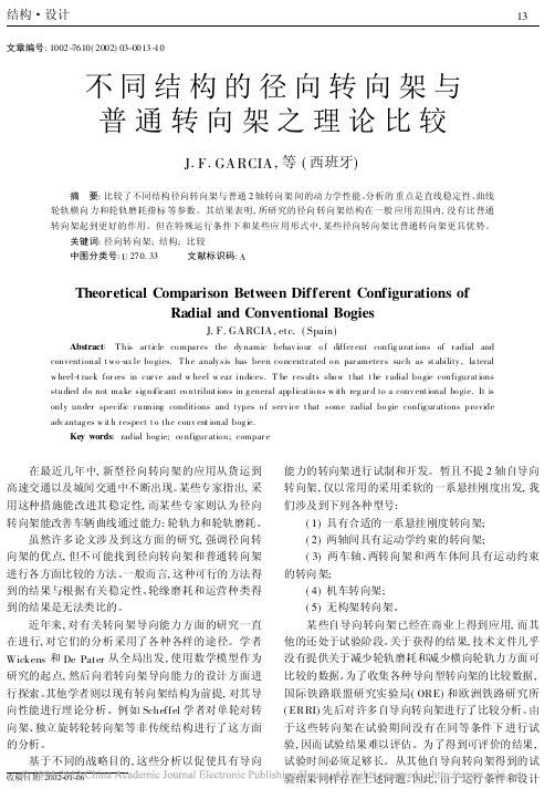
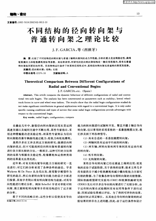
文章编号:1002-7610(2002)03-0013-10不同结构的径向转向架与普通转向架之理论比较J.F.GA RCIA,等(西班牙)摘 要:比较了不同结构径向转向架与普通2轴转向架间的动力学性能。
分析的重点是直线稳定性、曲线轮轨横向力和轮轨磨耗指标等参数。
其结果表明,所研究的径向转向架结构在一般应用范围内,没有比普通转向架起到更好的作用。
但在特殊运行条件下和某些应用形式中,某些径向转向架比普通转向架更具优势。
关键词:径向转向架;结构;比较中图分类号:U270.33 文献标识码:ATheoretical Comparison Between Different Configurations ofRadial and Conventional BogiesJ.F.GARCIA,etc.(Spain)Abstract:T his ar ticle co mpar es the dy namic behav io ur o f differ ent config urat ions of r adial and conventional t wo-ax le bo gies.T he analy sis has been co ncentr ated o n par ameter s such as st ability,la teral w heel-t rack for ces in cur ve and w heel w ear indices.T he r esults sho w t hat t he r adial bo gie configurat ions studied do not ma ke sig nificant co ntribut ions in g eneral applicatio ns w ith reg ar d to a conv ent ional bo gie.It is only under specific r unning conditions and types o f serv ice t hat some radial bo gie config ur ations pro vide adv antag es w it h r espect t o the conv ent ional bog ie.Key words:radial bog ie;co nfigur atio n;compar e 在最近几年中,新型径向转向架的应用从货运到高速交通以及城间交通中不断出现。
轨道车辆新型转向架Syntegra
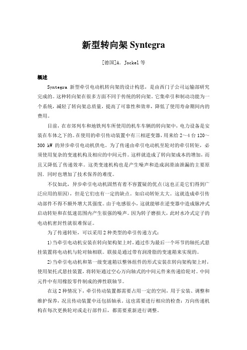
新型转向架Syntegra[德国]A.Jockel等概述Syntegra新型牵引电动机转向架的设计构思,是由西门子公司运输部研究完成的。
这种转向架在很多方面不同于传统的转向架。
它集牵引和制动功能为一个系统,减轻了转向架总质量,提高了可靠性和效率,降低了使用寿命期间内的费用。
目前,在市郊列车和地铁列车所使用的机车车辆的转向架中,电力设备是安装在车体之下的。
在使用的牵引传动装置中有三相逆变器,用来给2~4台120~300 kW的异步牵引电动机供电。
为了传递由牵引电动机至轮对的牵引转矩,必须使用复杂的变速机构及相应的中间元件。
这样就造成了转向架成本的增加,而且又降低了传递效率。
这类变速机构也是产生噪声和造成润滑油泄漏的主要原因.同时也增加了技术保养的难度。
不仅如此,异步牵引电动机固然有着不容置疑的优点(这也正是它们得到广泛应用的原因),但是它们也有一定的缺点。
如启动转矩太大。
这就造成牵引传动部件不得不额外增大其强度。
由于电感很小,这就能够在逆变器中造成脉冲式启动转矩和在低速范围内产生很强的噪声。
因为转子磨损大,此时水冷式定子的电动机密封性就很难保证。
为了传递转矩,可以采用2种类型的牵引传递方式:1)当牵引电动机安装在转向架构架上时,通过作为最后一个环节的轴托式悬挂装置将电动机与轮对轴相联。
联接是通过带有润滑脂的变速箱来实现的。
2)当牵引电动机和第一级变速箱以整体组件的形式安装在转向架构架上时,使用架托式悬挂装置,将转矩通过空心万向轴式的中间元件来传递给轮对。
中间元件中有用橡胶零件制成的弹性联轴节。
在这2种情况下,牵引传动装置都需要占用一定的空间,用于安装、调整和维护保养,况且传动装置中还包括轴承。
这也需要进行相应的检查:万向传递机构在每次更换轮对或走行部件后,都需要重新进行调整。
研制新转向架的目的是用非常简单的syntegra转向架来取代传递结构复杂的转向架。
这种syntegra转向架不用变速器,可直接将永磁励磁的大转矩同步牵引电动机的转矩传递给轮对。
- 1、下载文档前请自行甄别文档内容的完整性,平台不提供额外的编辑、内容补充、找答案等附加服务。
- 2、"仅部分预览"的文档,不可在线预览部分如存在完整性等问题,可反馈申请退款(可完整预览的文档不适用该条件!)。
- 3、如文档侵犯您的权益,请联系客服反馈,我们会尽快为您处理(人工客服工作时间:9:00-18:30)。
This article was downloaded by: [Southwest Jiaotong University]On: 06 June 2015, At: 17:29Publisher: Taylor & FrancisInforma Ltd Registered in England and Wales Registered Number: 1072954 Registered office: Mortimer House, 37-41 Mortimer Street, London W1T 3JH, UKVehicle System Dynamics: International Journal ofVehicle Mechanics and MobilityPublication details, including instructions for authors and subscription information:/loi/nvsd20Theoretical Comparison Between DifferentConfigurations of Radial and Conventional BogiesJ.F. Garcia , X. Olaizola , L.M. Martin & J.G. GimenezPublished online: 09 Aug 2010.PLEASE SCROLL DOWN FOR ARTICLEŽ.Vehicle System Dynamics,332000,pp.233–2590042-3114r 00r 3304-0233$15.00q Swets &ZeitlingerTheoretical Comparison Between DifferentConfigurations of Radial and Conventional Bogies J.F.GARCIA ),X.OLAIZOLA ),L.M.MARTIN)and J.G.GIMENEZ ))SUMMARY This article compares the dynamic behaviour of different configurations of radial and conventional two-axle bogies.In general,the design parameters for a better curve negotiation are not compatible with those for good stability.As the main target of this article is to compare the curving performances of different bogies under the same design basis,several bogie configurations with the same level of stability,obtained by choosing proper primary suspension stiffnesses,have been used.The comparison includes a conventional bogie and three radial bogies with differing self-steering and forced-steering principles in three different passenger services:High Speed,Regional and Mass Transit.The analysis has been concentrated on parameters such as stability,lateral wheel-track forces in curve and wheel wear indices.The results show that the radial bogie configurations studied do not make significant contributions in general applications with regard to a conventional bogie.It is only under specific running conditions and types of service that some radial bogie configurations provide advantages with respect to the conventional bogie. 1.INTRODUCTION In the last few years new radial bogie applications have emerged for services from freight transportation to high-speed transit and intercity services.Some technical w x authors emphasise improved stability with this type of solutions 1.Others claim improved behaviour with regard to the vehicle curving ability properties:axle-track w x forces and both wheel and rail wear 2.Although many technical papers have been written on this topic emphasising the advantages of this type of bogies,it has not been possible to find a surveywhich has carried out an exhaustive comparison of the advantages and disadvan-tages of this type of bogies with respect to conventional bogies.In general,the surveys available provide results which are not comparable on a common basis of performance with regard to stability,wheel wear or type of service.)Construcciones y Auxiliar de Ferrocarriles,S.A.,P.O.Box.2,20.200Beasain,Spain.))Escuela Tecnica Superior de Ingenieros Industriales.Universidad de Navarra,P.O.Box.1555,´20.009San Sebastian,Spain.And Construcciones y Auxiliar de Ferrocarriles,S.A.,P.O.Box.2,20.200Beasain,Spain.D o w n l o a d e d b y [S o u t h w e s t J i a o t o n g U n i v e r s i t y ] a t 17:29 06 J u n e 2015J.F.GARCIA ET AL.234In recent years theoretical work has been carried out on the steering ability of a number of bogies.There have been various approaches to their analysis.Wickens w x w x 3–5and De Pater 6approached the problem from a synthetic point of view,using a mathematical model as their starting point and moving towards the design of a bogie with this steering ability.Other authors have started with the premise of existing bogie configurations and have made theoretical deductions regarding their steering ability.For example,this analysis has been carried out by Dukkipati,w x w x w x Swamy and Osman 7,Scheffel,Frohling and Heyns 8and Frederich 9in the ¨Žfield of unconventional solutions one-wheelset bogies,Independently Rotating .Wheels bogies .Some of these analyses have given rise to experimentation and development of bogies with steering ability based on a variety of strategies.Apart from two-axle self-steering bogies,based solely on the use of soft primary suspension stiffnesses,which are in common use,we could mention the following types:bogies with w x adaptive primary suspension stiffnesses 10;bogies with kinematic joints between w x the axles 11,bogies with kinematic joints between axles and between bogies and w x w x w x carbody 12,locomotive bogies 13,14and bogies without frame 15.Some self-steering bogies are used commercially and others are still undergoing experimentation.With regard to the results obtained,the technical literature provides little comparative data concerning either:improved reduction of lateral wheel-rail forces and reduction of wheel and rail wear.In a bid to collect Žcomparative data from various bogie-steering strategies,the ORE Office de Recherches et d’Essais de l’Union Internationale des Chemins de Fer -The .International Rail Union’s Research and Tests Office and subsequently the ERRI Ž.European Rail Research Institute ,carried out a comparative survey of a number w x of self-steering bogies 16.The results of the tests are difficult to assess,since the bogies did not run under the same conditions during the experimental period,a period of time which must be lengthy in order to obtain appreciable results.The same is true of the experimental results obtained from other self-steering bogies,for which a comparative survey with conventional ones cannot be carried out since neither operating conditions nor the design criteria were not the same.In view of the technical data available for the radial bogies and the advantages Žthese could provide regarding improved stability increased speed on tangent .Ž.tracks ,less wheel-rail loads increased speed on curves and less wear to wheels Ž.and rails lower maintenance costs and less noise ,the decision was made to carry out a theoretical comparison of the performances for various types of steering mechanisms.The comparison has to be made applying the different bogie configu-rations to the same vehicle,under the same operating conditions.The same design specifications have to be used to define some specific parameters that determine stability and curving behaviour.Moreover the results are compared with those of a conventional bogie.In particular,the use of the same dynamic stability requirements for all the different bogie designs compared is important.It is well known that a reduction of the primary longitudinal stiffnesses leads to an improvement of the curving D o w n l o a d e d b y [S o u t h w e s t J i a o t o n g U n i v e r s i t y ] a t 17:29 06 J u n e 2015COMPARING DIFFERENT CONFIGURATIONS OF BOGIES 235performances of the vehicle,but in general,under an optimum value,such a reduction provokes a loss of dynamic stability.In this way,a comparison of curving performances,in which the stability performance requirement is not the same for all the bogie configurations,does not reach any valid assessment of their relative advantages and disadvantages.Due to this,the first phase of the strategy followed for the comparison of different basic designs consists of determining the minimum value of the longitu-dinal primary stiffness compatible with a common required dynamic stability and Ž.other vehicle performances brake,maximum lateral displacements and traction .The main purpose of this paper is to compare the curving behaviour of different basic radial bogie designs satisfying the same stability requirements.Bearing in mind that the results may vary depending on the area of application,the study has been established for three different areas:High Speed,Regional and Mass Transit services.The parameters used for comparison of the curving performance are the difference between the axle lateral forces of the wheelsets of the same bogie and the wear of the leading outer wheel.Modern current dynamic simulation tools allow us to model the dynamic behaviour of the vehicle to a degree of accuracy which is sufficient to ensure the validity of the comparative survey.The comparative survey analysed in this article w x was carried out with the SIDIVE dynamic simulation program 17.A summary of w x the main features of this program can be found in Ref.18.The correctness of the w x results was checked in a VSD Benchmark 19,20.2.CONFIGURATIONS STUDIED We have reduced the various radial bogie designs found in the bibliographical revision to the four configurations covered in this section.They all start with the same vehicle design,to which the specific components of each configuration have been adapted.For simulations,no account has been taken of increased vehicle weight due to the added components of each particular kinematic configuration and the imposed constraints are ideal.It can be assumed that the behaviour of a real implementation will be intermediate between the results shown in this paper and those of a conventional bogie.The following is a brief explanation of each configuration.2.1.Configuration 1ØDefinition :conventional 2-axle bogie as shown in Figure 1.ØPrinciple outline :see Figure 1.ØDegrees of freedom of each bogie :ØDX1,DX2and DXb absolute longitudinal displacements of both wheelsets and bogie,respectively.D o w n l o a d e d b y [S o u t h w e s t J i a o t o n g U n i v e r s i t y ] a t 17:29 06 J u n e 2015J.F.GARCIA ET AL.236Fig.1.Conventional Bogie.ØDY1,DY2and DYb absolute lateral displacements of both wheelsets and bogie,respectively.ØGZ1,GZ2and GZb yaw rotations of both wheelsets and bogie,respectively.2.2.Configuration 2ØDefinition :bogie with 2crossed bars connecting both wheelsets.The bars are rigid and their mass has been considered negligible.The bars are not connected in its mid point.See Figure 2.ØPrinciple outline :ØKinematic constraints :DY1-S )GZ1s DY2q S )GZ2;DX1sDX2Fig.2.Bogie with two crossbars connecting both axles.D o w n l o a d e d b y [S o u t h w e s t J i a o t o n g U n i v e r s i t y ] a t 17:29 06 J u n e 2015COMPARING DIFFERENT CONFIGURATIONS OF BOGIES237Fig.3.Bogie configurations equivalent to that of the Fig.2.For small movements,this configuration is kinematically equivalent to those shown in Figures 3a and 3b:2.3.Configuration 3ØDefinition :conventional bogie in which the axle boxes for the same side are joined by 2bars hinged onto an equalising bar which has its centre articulated on bogie frame.The bars are rigid and their mass has been considered negligible.ØPrinciple outline :see Figure 4Ž.ØKinematic constraints :GZb s GZ1q GZ2r 2;Ž.DXb s DX1q DX2r2Fig.4.Schematic representation of configuration 3.D o w n l o a d e d b y [S o u t h w e s t J i a o t o n g U n i v e r s i t y ] a t 17:29 06 J u n e 2015J.F.GARCIA ET AL.238Fig.5.Schematic representation of a configuration similar to 3.The results obtained for this kinematic configuration are similar to those obtained for the configuration shown in Figure 5.In this case the two kinematic chains are joined by an additional rigid bar.If the chain of one side brings the axle boxes near a certain distance,the chain of the other side moves the other axle boxes away the same distance.An additional constraint has to be consider for this configuration.The equation is DX1s DX2,which exerts no practical influence over the results,and for this reason it has not been considered as a different configuration.2.4.Configuration 4ØDefinition :forced-steering bogie.This is similar to that used in configuration 3,but with a kinematic linkage to the car body.The relative bogie r car body rotation creates a proportional relative rotation between the axles.ØPrinciple outline :see Figure6Fig.6.Schematic representation of configuration 4.D o w n l o a d e d b y [S o u t h w e s t J i a o t o n g U n i v e r s i t y ] a t 17:29 06 J u n e 2015COMPARING DIFFERENT CONFIGURATIONS OF BOGIES 239Ž.ØKinematic restrictions :GZ1s GZb )1q K y GZc )KŽ.GZ2s GZb )1y K q GZc )KDX1s DX2s DXb s DXcK s S r ScWhen K s S r Sc and the vehicle is within a curve of constant radius the orientation of the axles and of the bogie becomes radial.3.METHODOLOGYAs mentioned above,SIDIVE program has been used as a vehicle dynamic simulation tool.The modelling of the vehicles takes into account several types of non-linearities:suspension elements,wheel-rail contact geometry and contact forces.The geometry of the wheel-rail contact has been modelled on the YZ plane Ž.plane perpendicular to the track axis .The relationship between contact forces w x w x and creepage is based on the simplified theory of Kalker 21.In the Ref.22a description of the geometric modelling and the wheel-rail forces calculation used in SIDIVE program is shown.The dynamic stability analysis included in this paper has been carried out by linearizing the non-linear equations of the vehicle model around the equilibrium position.The analysis of the curving behaviour is obtained by calculating the quasi-static equilibrium position of the non-linear model when negotiating curves.A description of the corresponding equations of the curving negotiation are w x included in Ref.23.As cited in Section 2,a VSD Benchmark shows the correctness of the stability and curving results of this program.The vehicle model used for all simulations consists of a car body and two powered bogies.Air springs and anti-roll bars are used as secondary suspension.The secondary suspension does not apply any Z-axis torque between the carbody and the bogies.No traction forces are considered.Anti-yaw dampers are not installed.The data corresponding to the most important parameters are included in the annex.Three areas of application in accordance with speeds and type of service have been considered.These areas are as follows:ØHIGH-SPEED :intercity rail service with maximum speeds between 200Km r h and 300Km r h.These vehicles must be designed to run on high-speed railway lines and also on conventional tracks with small-radius curves.ØREGIONAL :rail service for journeys between 150and 500Km,as back-up to the intercity routes.The speeds attained do not exceed 160Km r h,and the lines contain a high percentage of curves with radii greater than 250m.ØMASS TRANSIT :this denomination includes rail service for Mass Transit transport in cities and city suburbs.It also includes local train services and underground rail systems.Speeds do not exceed 80Km r h and,in general,the percentage of line curves is high.D o w n l o a d e d b y [S o u t h w e s t J i a o t o n g U n i v e r s i t y ] a t 17:29 06 J u n e 2015J.F.GARCIA ET AL.240The same model described above has been used for each area of application,with the peculiarities of each service as shown in the annex.In most practical applications,radial bogies have been used for improving curving behaviour while maintaining an acceptable level of stability.In this study we will compare the curving performances of several bogie configurations with design parameters assuring the same level of stability.This is why the first phase of the methodology followed consists of a selection of the values of the primary suspension stiffnesses for each configuration and area of application,compatible with the proposed stability criterion.In the second phase of the methodology the curving performances of each configuration are calculated and compared.The analysis of each type of bogie and each service has been divided into two phases:3.1.Phase 1:Selection of primary suspension stiffnesses Kx1,Ky1Ž.The goal of this phase is to determine the pair of values Kx1,Ky1with the least stiffness Kx1assuring a common pre-specified level of stability for each of the 4configurations:As an example of optimisation of primary suspension stiffnesses,Figure 7Ž.shows the stability maps for the conventional bogie model configuration 1in the Ž.MASS TRANSIT service.These maps show the percentage %of damping for the least-damped vibration mode as a function of primary suspension stiffnesses Kx1and Ky1for two equivalent conicities:0.05which simulates new wheel profiles,and 0.4for extremely worn profiles as required for many European w x Administration and suggested by some authors 24.In this case,the values selected for Kx1and Ky1were 3.2MN r m and 7.5MN r m respectively.Those values correspond to a point of the stability maps in which Kx1is the minimum Žvalue compatible with the required stability damping ratio 10%for this applica-.tion .In general,a high value of Ky1allows to reduce the Kx1.In this particular case,it has been considered that a value of 7.5MN r m for Ky1is high enough so that any additional increase of it only gives very small improvements of stability.On the other hand,the practical implementation of higher values of Ky1may originate some difficulties.For the chosen values of the primary stiffnesses,the minimum damping percentage is over 10%for both extreme conicities.3.2.Phase 2:Analysis of curving behaviourThis phase is devoted to the analysis of the curving behaviour of the four bogie Žconfigurations.Wear indices and the difference between the lateral forces H .forces difference of both axles corresponding to the same bogie are used for comparison between different configurations.We will call axle lateral force or ‘‘H force’’the sum of the lateral forces acting on both wheels of the same axle and we will call ‘‘H forces difference’’the difference between the H forces of both axlesD o w n l o a d e d b y [S o u t h w e s t J i a o t o n g U n i v e r s i t y ] a t 17:29 06 J u n e 2015COMPARING DIFFERENT CONFIGURATIONS OF BOGIES241Ž..Fig.7.Damping ratio %of the least damped vibration mode.MASS TRANSIT service.a Equiva-.lent conicity:0.05.b Equivalent conicity:0.4.corresponding to the same bogie.The ranges of curve radii considered in the studyare different for each area of application:80to 1200m for MASS TRANSIT service,250to 1200m for REGIONAL service and 250to 4000for HIGH SPEED service.For the HIGH-SPEED and REGIONAL services,the operating conditions Žconsidered are for a tilting train with a cant deficiency additional cant to be added .to the actual cant of the track to balance the lateral centrifugal force of 276mm Ž2.uncompensated lateral acceleration of 1.8m r s .For the MASS TRANSIT-type Žservice cant deficiency is 153mm uncompensated lateral acceleration of 1.02.m r s .Thus it is ensured that the sum of H forces of all the vehicle’s axles is the same for all curve radii under consideration.D o w n l o a d e d b y [S o u t h w e s t J i a o t o n g U n i v e r s i t y ] a t 17:29 06 J u n e 2015There is an allowable limit H ,called Prud d’Homme limit,for the axle lim Ž.w x lateral force ‘‘H forces’’25.The total lateral force per bogie must be equal to the sum of these H forces on both axles.The longitudinal friction forces at the wheel-rail contact create a moment on the vertical axis of the bogie that is compensated by unbalancing the axle lateral forces,H forces,of both axles.In this way,the H force in one of the axles increases,approaching the Prud d’Homme limit.The optimum situation shall be when these forces are equal for both axles of the same bogie,i.e.,when H1y H2s 0.The representation of forces difference,H1y H2,thus helps us to analyse the level of aggression of the vehicle on the track.Figure 8shows by way of example the H forces difference between the first Ž.Ž.axle H1and the second axle H2for the case of the conventional bogie Ž.configuration 1for MASS TRANSIT-type services.Figures of this type show at least two differentiated zones.One of these is for high curvature radii,in which the lateral force in the rear axle is greater than that Ž.of the front axle H1-H2negative .For these curve radii the axles rotate with respect to the bogie frame at a wider angle than that demanded to adopt a radial position,and the bogie adopts a negative attack angle relative to the track.In the other zone,for small curvature radii,the loads in the front axle are greater than those borne by the rear axle.In these cases,the longitudinal forces of friction are insufficient to make the axles rotate with respect to the bogie frame at the angle necessary to attain the radial position.Thus the bogie adopts a positive attack angle,creating greater forces in the front axle than in the rearaxle.Ž.Fig.8.Difference of axle lateral forces H1y H2for the conventional bogie and MASS TRANSIT-service train.D o w n l o a d e d b y [S o u t h w e s t J i a o t o n g U n i v e r s i t y ] a t 17:29 06 J u n e 2015The wear performance associated to each type of bogie is analysed by a wear w x index WI according to the expression 26:)w 2x WI s T g r A N r mm whereT:friction force g :creepage A:contact area.This wear index is shown in graphs plotted for the same range of curve radii as the axle lateral loads.Figure 9shows an example of this graph for a conventional bogie used in MASS TRANSIT services.We can also appreciate two differenti-ated zones:one with moderate wear for wide curve radii,and another with a Ž.notable increase in wear severe wear for smaller curvature radii.The separation between the two zones approximately coincides with the change in sign of the H forces difference H1-H2observed in Figure 8.A move to severe wear at the contact areas can also be associated with insufficient friction forces to steer the axles to the position radial to the curve.As the radius of the curves becomes smaller the longitudinal displacement of the primary suspension required to assure a position of the axles radial to the curve becomes greater.Under a specific curve radius,friction forces at the wheel-rail contact are not enough to overcome the longitudinal stiffness of the primary suspension.This curve radius establishes the border between two clearly differentiated curving behaviours of the vehicle.4.RESULTSIn this section,the aforementioned 3areas of applications are analysed following Žthe methodology explained in Section 3.Curving performances defined bybothFig.9.Wear index calculated at the attack wheel of the conventional bogie for MASS TRANSITservice versus curve radius.D o w n l o a d e d b y [S o u t h w e s t J i a o t o n g U n i v e r s i t y ] a t 17:29 06 J u n e 2015.H y H and wear index of different bogie configurations are compared.The 12same data have been used for all bogie configurations,except the proper kinematic constraints of each configuration and the primary suspension stiffnesses Kx1and Ky1.For each bogie configuration,the values of Kx1and Ky1are chosen to reach Ž.a common dynamic stability performance damping ratio .The selection of Kx1and Ky1is a previous step carried out in the analysis of each configuration and type of service.The following sections show the curving results corresponding to each type of service and bogie configuration,also including the criteria followed to select Kx1and Ky1stiffnesses.4.1.HIGH-SPEED serviceIn HIGH SPEED service,the main design criterion is to guarantee the dynamic w x stability of the vehicle.According to different authors 1,radial bogies have potential advantages regarding the dynamic stability so that they could find in the HIGH SPEED service an important area of application.It also is of great interest checking both,if radial bogies improve really the dynamic stability as compared with conventional bogies,and whether this improvement of the stability is not accompanied of an important loss of the curving performances,as occurs for conventional bogies.4.1.1.Selection of primary suspension stiffnessesRegarding the HIGH-SPEED service,the criterion followed for selection of primary suspension stiffnesses Kx1and Ky1is to obtain the lowest value of Kx1assuring a damping ratio of greater than 0%under the following two conditions:Øequivalent conicity of 0.05.Øequivalent conicity of 0.35.The speed used in the calculation was 300Km r h,currently the maximum speed of revenue service in Europe.The required damping value is low in comparison to the value sought in the case of the MASS TRANSIT service,since the vehicles used in this service have anti-yaw dampers which improve stability.These dampers have not been included in our analysis since their marked non-linear character makes their results extremely dependent on the specific conditions of the calculation carried out.On the other hand,in HIGH SPEED service,the wheel and track maintenance is more strict so that the equivalent conicity range used in this study has been shortened to the range 0.05–0.35.Table 1.Primary suspension stiffnesses for HIGH-SPEED service.()()ConfigurationKx1MN r m Ky1MN r m 111.420.02 5.0 2.039.020.0477.56.7D o w n l o a d e d b y [S o u t h w e s t J i a o t o n g U n i v e r s i t y ] a t 17:29 06 J u n e 2015The application of these criteria to the four bogie configurations resulted in the selection of the Kx1and Ky1values shown in Table 1.Some remarks have to be made regarding the figures shown in Table 1.Apart Ž.from the results corresponding to the conventional bogie configuration 1,in the rest of cases different kind of problems have arisen:.The values selected for the radial bogie configuration 2correspond to a critical point.Any increase in Ky1with respect to the value shown in this table makes the bogie unstable for worn profiles.Bearing in mind that the selected value of Ky1is extremely low,in practical solutions it only conserves this low stiffness for very low lateral forces.In this way,a situation of high limit cycle oscillation could be reached in which the effective resultant value of Ky1is higher than the nominal one,and this could lead to unstable vibrations,despite the fact that the design values are nominally stable..In the case of the radial bogie configuration 3,it proved impossible to find a point which complied with the proposed stability criterion.In any case a pair of values was taken for Kx1and Ky1providing damping for the least-damped Ž.vibration mode of y 1.4%,running with new profiles equivalent conicity of 0.05..Ž.For the forced-steering bogie configuration 4,dynamic stability could only be reached using an extremely high value for the stiffness Kx1,as may be observed in Table 1.In addition to the inconveniences associated with selection of high stiffness values,it must be said that the vehicle becomes unstable when running at speeds between 40Km r h and 80Km r h with conicities bordering on 0.05.The previous Table shows that using kinematic constraints corresponding to the Ž.radial bogies configurations 2and 3allows to use primary suspension stiffnesses Ž.softer than those in the conventional case configuration 1.4.1.2.H forces difference:H1-H2Figure 10shows the difference of H forces corresponding to the axles of the first Žbogie for the various configurations.Data for the forced-steering bogie configura-.tion 4have not been included since they are out of range with regard to wear and to H forces difference,due to the high value of longitudinal stiffness Kx1.For comparison and in order to check the influence of the Kx1value on the Ž.wheel-rail forces,the results for a conventional bogie configuration 1with extremely high stiffness Kx1have been added to the graphs.The stiffnesses considered for this bogie are:Kx 1s Ky 1s 100MN r mThis bogie-reference is called ‘‘stiff bogie’’.Analysis of Figure 10produces the conclusion that differences between the bogie configurations and also between them and the stiff bogie are of little relevance.Ž.It should be said of this Figure that the H forces difference H -H is 12substantially higher in wide-radius curves than in small radius curves.In spite ofD o w n l o a d e d b y [S o u t h w e s t J i a o t o n g U n i v e r s i t y ] a t 17:29 06 J u n e 2015。