tibco adapter配置过程
Tibco 产品安装手册

TIBCO产品安装手册目录1引言 (1)1.1编写目的 (1)1.2预期读者 (1)1.3术语 (1)1.4参考资料 (1)2产品概述 (3)2.1目标 (3)2.2运行环境 (3)2.3产品架构 (3)2.3.1项目TIBCO产品简介 (4)3产品安装 (6)3.1安装TIBCO R UNTIME A GENT (6)3.1.1前置条件 (6)3.1.2安装步骤 (6)3.2安装TIBCO EMS (9)3.2.1前置条件 (9)3.2.2安装步骤 (10)3.3安装TIBCO A DMINISTRATOR (13)3.3.1前置条件 (13)3.3.2安装步骤 (13)3.4安装TIBCO B USINESS WORKS (18)3.4.1前置条件 (18)3.4.2安装步骤 (19)3.5安装TIBCO A DAPTER FOR A CTIVE D ATABASE (22)3.5.1前置条件 (22)3.5.2安装步骤 (22)3.6安装TIBCO A DAPTER FOR L OTUS N OTES (25)3.6.1前置条件 (25)3.6.2安装步骤 (26)3.7安装TIBCO A DAPTER FOR F ILES (30)3.7.1前置条件 (30)3.7.2安装步骤 (30)3.8安装TIBCO A DAPTER FOR S WIFT (33)3.8.1前置条件 (33)3.8.2安装步骤 (33)3.9安装TIBCO IPROCESS E NGINE (36)3.9.1前置条件 (36)3.9.2安装步骤 (37)3.10安装TIBCO IPROCESS M ODELER (39)3.10.1前置条件 (39)3.10.2安装步骤 (39)4技术支持 ...................................................................................................... 错误!未定义书签。
Tibco 产品安装手册

TIBCO产品安装手册目录1引言 (1)1.1编写目的 (1)1.2预期读者 (1)1.3术语 (1)1.4参考资料 (1)2产品概述 (3)2.1目标 (3)2.2运行环境 (3)2.3产品架构 (3)2.3.1项目TIBCO产品简介 (4)3产品安装 (6)3.1安装TIBCO R UNTIME A GENT (6)3.1.1前置条件 (6)3.1.2安装步骤 (6)3.2安装TIBCO EMS (9)3.2.1前置条件 (9)3.2.2安装步骤 (10)3.3安装TIBCO A DMINISTRATOR (13)3.3.1前置条件 (13)3.3.2安装步骤 (13)3.4安装TIBCO B USINESS WORKS (18)3.4.1前置条件 (18)3.4.2安装步骤 (19)3.5安装TIBCO A DAPTER FOR A CTIVE D ATABASE (22)3.5.1前置条件 (22)3.5.2安装步骤 (22)3.6安装TIBCO A DAPTER FOR L OTUS N OTES (25)3.6.1前置条件 (25)3.6.2安装步骤 (26)3.7安装TIBCO A DAPTER FOR F ILES (30)3.7.1前置条件 (30)3.7.2安装步骤 (30)3.8安装TIBCO A DAPTER FOR S WIFT (33)3.8.1前置条件 (33)3.8.2安装步骤 (33)3.9安装TIBCO IPROCESS E NGINE (36)3.9.1前置条件 (36)3.9.2安装步骤 (37)3.10安装TIBCO IPROCESS M ODELER (39)3.10.1前置条件 (39)3.10.2安装步骤 (39)4技术支持 ...................................................................................................... 错误!未定义书签。
TIBCO相关产品介绍

1相关产品介绍本节对TIBCO部分产品进行详细介绍。
1.1TIBCO BusinessWorksTIBCO BusinessWorks简称BW,是一个可扩展的SOA集成框架,是TIBCO数据交换平台的核心组件,BW是一款非常易于使用的集成应用解决方案工具,用于进行业务集成和Web Service的开发、部署及管理,能够与各种应用系统连接。
TIBCO BusinessWorks有如下特性:●使用方便且功能强大的自动化流程引擎(Process Engine),基于BW能够快速设计、开发和部署跨越多个应用系统的复杂的集成应用。
●符合SOA架构设计标准,支持工业标准,提供了完整的Web Service解决方案,支持SOAP,WSDL,UDDI,WS-Security等技术和标准规范,能够快速开发Web Service应用。
⏹SOAP组件⏹WSDL组件⏹Web服务安全策略组件⏹Web Service服务流程⏹Web Service调用流程●内置众多的技术接口组件,能够与所有常见的应用系统进行连接交互,将这些组件进行组合,就能够开发出强大的集成应用。
⏹JMS组件⏹JDBC组件⏹FTP组件⏹邮件组件⏹TCP组件⏹RMI组件⏹HTTP组件⏹RV组件⏹适配器组件●支持文件接口,能够进行文件操作,包括文件创建、读取、拷贝、删除、移动等等,支持对文本文件和二进制文件的操作。
⏹文件组件●支持XML,支持对XML文件的拼装、解析,支持嵌入XSLT进行XML数据处理。
⏹XML组件●自动化流程提供多种事件触发方式,既可以根据消息请求进行触发,也能够进行定时触发。
⏹事件触发方式⏹定时触发方式●支持内容路由,能够根据流程中处理数据的内容,进行不同的处理,比如根据部门的不同将数据转发到不同的系统中。
●支持子流程调用,支持动态子流程调用,极大地提高了开发的重用性并简化了集成应用的复杂度。
●支持事务操作,包括JDBC事务和分布式事务,支持跨数据库的事务提交与回滚;通过引入外部分布式事务组件,能够将不同类型技术的操作置于同一事务进行提交与回滚,比如JDBC,JMS,EJB等。
Tuxedo测试环境搭建与配置v1.0.0
Windows下TUXEDO测试环境部署方案Version 1.0北京东华合创北美科技有限公司渠道应用部二零零九年四月二十日目录1:概述..................................................................................................... - 3 - 2:环境搭建............................................................................................. - 3 - 3:注意事项以及错误解决办法............................................................. - 8 -3.1 在命令行下编译server时出现得错误.................................... - 8 -3.2 配置tibco客户端注意事项.................................................... - 11 -1:概述1.1 编写目的由于中间业务(电信)前置系统测试需要通过Tuxedo来与第三方进行通信,为了便于以后熟悉了解Tuxedo,故编写此文档待以后进行参考查阅。
1.2 搭建环境简述操作系统:windowsTuxedo版本:version 8.1Tibco Tuxedo Adapter 版本:version 5.6.02:环境搭建2.1 Tuxedo 环境框架2.2.1测试环境框架图2.2.2测试环境安装配置客户端需要安装Tibco开发程序,及Tibco 下的Tuxedo Adapter version5.6.0(Tuxedo适配器),以及Tuxedo客户端version 8.1(建议选择full安装)。
POINT I O 连接基配置说明书

Installation InstructionsOriginal InstructionsPOINT I/O Wiring Base AssemblyCatalog Numbers 1734-TB3, 1734-TB3S, 1734-RTB3, 1734-RTB3SEnvironment and EnclosurePrevent Electrostatic DischargeAbout the AssemblyThe POINT I/O™ wiring base assembly consists of a mounting base (4) and a removable terminal block (RTB)(3). 1734-TB3 uses screw-clamp termination; 1734-TB3S uses spring-clamp terminations.Prepare the WiresInstall the Mounting BaseTo install the mounting base on the DIN rail (Allen-Bradley part number 199-DR1; 46277-3; EN50022), proceed as follows.1.Position the mounting base vertically above the installed units (adapter, power supply or existing module).2.Slide the mounting base down allowing the interlocking side pieces to engage the adjacent module or adapter.3.Press firmly to seat the mounting base on the DIN rail.he mounting base snaps into place.Install the ModuleThe module can be installed before or after base installation. Make sure that the mounting base is correctly keyed before installing the module into the mounting base. In addition, make sure that the mounting base locking screw is positioned horizontal referenced to the base.1734-MBe a bladed screwdriver to rotate the keyswitch on the mounting base clockwise until the number required for the type of module you are installing aligns with the notch in the base.2.Verify that the DIN rail locking screw is in the horizontal position.You cannot insert the module if the locking mechanism is unlocked.3.Insert the module straight down into the mounting base and press to secure.The module locks into place.ATTENTION: This equipment is intended for use in a Pollution Degree 2 industrial environment, in overvoltage Category II applications (as defined in EN/IEC 60664-1), at altitudes up to 2000 m (6562 ft) without derating.This equipment is not intended for use in residential environments and may not provide adequate protection to radio communication services in such environments.This equipment is supplied as open-type equipment for indoor use. It must be mounted within an enclosure that is suitably designed for those specific environmental conditions that will be present and appropriately designed to prevent personal injury resulting from accessibility to live parts. The enclosure must have suitable flame-retardant properties to prevent orminimize the spread of flame, complying with a flame spread rating of 5VA or be approved for the application if nonmetallic. The interior of the enclosure must be accessible only by the use of a tool. Subsequent sections of this publication may contain more informationregarding specific enclosure type ratings that are required to comply with certain product safety certifications.In addition to this publication, see the following:•Industrial Automation Wiring and Grounding Guidelines, publication 1770-4.1, for more installation requirements.•NEMA Standard 250 and EN/IEC 60529, as applicable, for explanations of the degrees ofprotection provided by different types of enclosure.ATTENTION: This equipment is sensitive to electrostatic discharge, which can cause internal damage and affect normal operation. Follow these guidelines when you handle this equipment.•Touch a grounded object to discharge potential static.•Wear an approved grounding wriststrap.•Do not touch connectors or pins on component boards.•Do not touch circuit components inside the equipment.•Use a static-safe workstation if available.•Store the equipment in appropriate static-safe packaging when not in use.ATTENTION: If this equipment is used in a manner not specified by the manufacturer, the protection provided by the equipment may be impaired.ATTENTION: Read this document and the documents listed in the Additional Resources section about installation, configuration, and operation of this equipment before you install, configure, operate, or maintain this product. Users are required to familiarize themselves with installation and wiring instructions in addition to requirements of all applicable codes, laws, and standards.ATTENTION: Installation, adjustments, putting into service, use, assembly, disassembly, and maintenance are required to be carried out by suitably trained personnel in accordance with applicable code of practice.ATTENTION: In case of malfunction or damage, no attempts at repair should be made. The module should be returned to the manufacturer for repair. Do not dismantle the module.ATTENTION: This equipment is certified for use only within the surrounding air temperature range of -20…+55 °C (-4…+131 °F). The equipment must not be used outside of this range.ATTENTION: Use only a soft dry anti-static cloth to wipe down equipment. Do not use any cleaning agents.Description Description 1DIN rail locking screw (orange)4Mounting base 2Removable Terminal Block (RTB) handle 5Interlocking side pieces 3Removable Terminal Block6Mechanical keying (orange)64489501234567891011Terminals 4, 5, 8, and 9 are internally shorted.Terminals 6, 7, 10, and 11 are internally shorted.Wiring Without Wire End FerruleWire Size Range Number of Wires Strip Length 8-position RTB12-position RTB0.25…2.5 mm²(22...14 AWG)116±1 mm (0.63±0.03 in)14±1 mm (0.55±0.03 in)218±1 mm (0.71±0.03 in)16±1 mm (0.63±0.03 in)Wiring With Wire End FerruleWire Size Range Number of Wires Strip Length Recommended Wire End Ferrule (1)(1)TWIN wire end ferrules are not recommended for wiring.8-position RTB12-position RTB0.75 mm² (18 AWG)116±1 mm (0.63±0.03 in)14±1 mm (0.55±0.03 in)Ferrule with insulating collar, in accordance with DIN 46228-4 and UL 486F.Sleeve length: 12 mm (0.47 in)18±1 mm (0.71±0.03 in)16±1 mm (0.63±0.03 in)ATTENTION: Do not wire more than 2 conductors on any single terminal.ATTENTION: This product is grounded through the DIN rail to chassis ground. Use zinc-plated chromate-passivated steel DIN rail to assure proper grounding. The use of other DIN rail materials (for example, aluminum or plastic) that can corrode, oxidize, or are poorconductors, can result in improper or intermittent grounding. Secure DIN rail to mounting surface approximately every 200 mm (7.8 in.) and use end-anchors appropriately. Be sure to ground the DIN rail properly. See Industrial Automation Wiring and Grounding Guidelines, Rockwell Automation publication 1770-4.1, for more information.44229Turn the keyswitch to align the number with the notch. Notch position 3 is shown.Publication 1734-IN013D-EN-P - February 2021 | Supersedes Publication 1734-IN013C-EN-P- December 2018Copyright © 2021 Rockwell Automation, Inc. All rights reserved. Printed in China.Rockwell Otomasyon Ticaret A.Ş. Kar Plaza İş Merkezi E Blok Kat:6 34752, İçerenköy, İstanbul, Tel: +90 (216) 5698400 EEE Yönetmeli ğine UygundurAllen-Bradley, expanding human possibility, FactoryTalk, POINT I/O, Rockwell Automation, and TechConnect are trademarks of Rockwell Automation, Inc.Trademarks not belonging to Rockwell Automation are property of their respective companies.Your comments help us serve your documentation needs better. If you have any suggestions on how to improve our content, complete the form at rok.auto/docfeedback .For technical support, visit rok.auto/support .PN-619315Waste Electrical and Electronic Equipment (WEEE)Rockwell Automation maintains current product environmental compliance information on its website at rok.auto/pec .At the end of life, this equipment should be collected separately from any unsorted municipal waste.Connect with us.Install the Removable Terminal BlockA Removable Terminal Block (RTB) is supplied with your wiring base assembly. To remove, pull up on the RTB handle. This allows the mounting base to be removed and replaced as necessary without removing any wiring. To reinsert the removable terminal block, proceed as follows.1.Insert the end opposite the handle into the base unit.This end has a curved section that engages with the wiring base.2.Rotate the terminal block into the wiring base until it locks itself in place.3.If an I/O module is installed, snap the RTB handle into place on the module.Remove a Mounting BaseTo remove a mounting base, you must remove any installed module, and the module installed in the base to the right. Remove the removable terminal block (if wired).1.Unlatch the RTB handle on the I/O module.2.Pull on the RTB handle to remove the removable terminal block.3.Press the module lock on the top of the module and pull on the I/O module to remove from the base.4.Repeat steps 1…3 for the module to the right.e a small bladed screwdriver to rotate the orange base locking screw to a vertical position.This releases the locking mechanism.6.Lift the mounting base straight up to remove.SpecificationsWARNING: For 1734-RTBS and 1734-RTB3S, to latch and unlatch the wire, insert a bladedscrewdriver (catalog number 1492-N90 – 3 mm diameter blade) into the opening at approximately 73° (blade surface is parallel with top surface of the opening) and push up gently.ATTENTION: Do not remove or replace a Terminal Base unit while power is applied. Interruption of the backplane can result in unintentional operation or machine motion.WARNING: Do not disconnect or replace component unless power is switched off or area is known to be nonhazardous. Do not pull on the installed wiring to remove a terminal base. A shock hazard exists if power is applied to the terminal base.GeneralAttributeValueField power bus supply voltage max 300V — 1734-TB3 and 1734-TB3S Field power bus supply current max 10 A — 1734-TB3 and 1734-TB3S Dimensions (HxWxD), approx.65 x 12 x 160 mm (2.56 x 0.47 x 6.25 in.)Weight approx.97.5 g (3.44 oz) — 1734-TB387.0 g (3.07 oz) — 1734-TB3S Wire category (1) (2)(1)Use this conductor category information for planning conductor routing as described in Industrial Automation Wiring and Grounding Guidelines, publication 1770-4.1.(2)Use this Conductor Category information for planning conductor routing as described in the appropriate System Level Installation Manual.Dependent on installed moduleWire size0.25…2.5 mm² (22…14 AWG) solid or stranded copper wire that is rated at 75 °C (167 °F), or greater, 1.2 mm (3/64 in.) insulation max Signal terminal voltage max 300V — 1734-TB330V — 1734-TB3SSignal terminal current max 2 A — 1734-RTB3 and 1734-RTB3SIsolation voltage 250V, Basic Insulation Type, field-side to system, Type tested at 1000V AC for 60 s Enclosure type ratingNone (open-style)Terminal base screw torque 0.8 N•m (7 lb•in) — 1734-TB3 onlyEnvironmental SpecificationsAttributeValueTemperature, operatingIEC 60068-2-1 (Test Ad, Operating Cold),IEC 60068-2-2 (Test Bd, Operating Dry Heat),IEC 60068-2-14 (Test Nb, Operating Thermal Shock):-20…+55 °C (-4…+131 °F)Temperature, surrounding air, max 55 °C (131 °F)Temperature, nonoperating IEC 60068-2-1 (Test Ab, Unpackaged Nonoperating Cold),IEC 60068-2-2 (Test Bb, Unpackaged Nonoperating Dry Heat),IEC 60068-2-14 (Test Na, Unpackaged Nonoperating Thermal Shock):-40…+85 °C (-40…+185 °F)Relative humidity IEC 60068-2-30 (Test Db, Unpackaged Damp Heat): 5…95% noncondensing VibrationIEC 60068-2-6 (Test Fc, Operating): 5 g @ 10…500 Hz Shock, operating IEC 60068-2-27 (Test Ea, Unpackaged Shock): 30 g Shock, nonoperatingIEC 60068-2-27 (Test Ea, Unpackaged Shock): 50 gCertifications (1734-TB3 and 1734-TB3S only)Certification (when the product ismarked)(1)(1)See the Product Certification link at rok.auto/certifications for Declarations of Conformity, Certificates, and other certification details.Valuec-UL-usUL Recognized Component Industrial Control Equipment, certified for US and Canada.See UL File E195367.CEEuropean Union 2014/30/EU EMC Directive, compliant with:EN 61131-2; Programmable Controllers (Clause 8, Zone A & B)EN 61326-1; Meas./Control/Lab., Industrial Requirements EN 61000-6-2; Industrial Immunity EN 61000-6-4; Industrial Emissions European Union 2014/35/EU LVD, compliant with:EN 61131-2; Programmable Controllers (Clause 11)European Union 2011/65/EU RoHS, compliant with:EN 50581; Technical DocumentationRCMAustralian Radiocommunications Act, compliant with:AS/NZS CISPR 11; Industrial EmissionsKC Korean Registration of Broadcasting and Communications Equipment, compliant with:Article 58-2 of Radio Waves Act, Clause 3EACRussian Customs Union TR CU 020/2011 EMC Technical RegulationRussian Customs Union TR CU 004/2011 LV Technical Regulation。
TIBCO产品问答

TIBCO产品问答1.消息中间件TIBCO EMS1.1.是否符合JMS标准JMS是由Sun微系统公司开发的一套企业报文发送规范,属于J2EE的一部分。
它提供了基于队列(点对点,比如IBM MQ)和发布订阅(比如TIBCO RV)方式的API。
TIBCO遵循Sun的JMS规范开发了EMS,并且提供了高性能和许多其它的特性,包括:●认证和访问控制●管理工具●可靠发布和无确认接收●TIBCO RV和TIBCO SmartSocket的连接TIBCO EMS 5.1通过了Sun Microsystem 兼容工具测试针对JMS 1.1的测试,完全兼容JMS 1.1规范。
TIBCO EMS基于C语言开发,相对于基于Java开发的JMS实现产品拥有更好的性能。
1.2.是否支持主题(TOPIC)消息模型?TIBCO EMS支持TOPIC消息模型,即发布订阅(Publish/Subscribe)消息传输方式。
发布者将消息发送到TOPIC上,订阅者从TOPIC上接收消息。
可以有多个发布者向同一个TOPIC发送消息,多个订阅者可以从同一个TOPIC上接收消息。
发布者可以把相同的消息发送给多个订阅者,当多个订阅者都连接到EMS 服务器,并从同一个TOPIC上接收消息,发布者将消息发送到TOPIC上,所有的正与TOPIC连接的订阅者都能接收到消息,以此实现消息的一对多传输。
1.3.主题(TOPIC)如何保证消息的可靠传输?在普通的发布订阅方式中,订阅者只有处于活动状态的时候,才能从TOPIC 上接收消息,即订阅者要连接到JMS服务器。
如果当消息发送到TOPIC时,订阅者并没有连接到JMS服务器,那订阅者再连接的时候,将无法接受这些消息。
TIBCO EMS支持持久化订阅(Durable Subscribe)方式。
订阅者在TOPIC上建立持久化订阅,当消息发布者将消息发送到TOPIC时,即使在订阅者没有连接EMS 服务器,消息也会存储在订阅者的持久化订阅中,这些消息存储在EMS服务器上,即使服务器重新启动也不会丢失;当订阅者再次连接EMS服务器时,就可以接受这些消息。
TIBCO和MES集成解决方案

TIBCO和MES集成解决方案1引言1.1编写目的用于使用TIBCO中间件集成MES系统的指导,阐述关键技术构件及具体的集成实现。
1.2 TIBCO背景TIBCO是一家有着20年历史的老牌中间件公司,致力于企业应用集成产品和解决方案的领域;是世界上最大的独立业务整合软件公司;总部在美国硅谷,NASDAQ上市企业,TIBCO最大的竞争对手仅为IBM。
在企业应用集成领域中,处于世界范围内No. 1。
1.3引用术语与解释TIBCO RV是一款主流的消息中间件产品,它具有发布/订阅(Publish/Subscribe)、基于主题寻址(Subject-Based Addressing) 和自定义数据信息(Self-Describing Data Messages)等专利技术功能。
使用XML进行消息传递交互。
2关键技术构件本组件包括下面几个常用接口,分别如下:1)TIBCO.Rendezvous.dll(TIBCO RV):TIBCO核心组件2)TibrvAdapter.AddTibrvListener:创建一个监听器接口3)TibrvAdapter.InitializeAdapter: 初始化连接接口4)TibrvAdapter .RequestAsync:发送消息接口5)TibrvListener.OnMessage:监听消息接口6)官方辅助类:TibrvAdapter、TibrvListener、TibrvManager 3 环境配置3.1 TIBCO客户端1)应用程序服务器需要安装TIBCO客户端2)应用程序引用TIBCO.Rendezvous.dll4 组件接口使用说明4.1 AddTibrvListener实现TibrvAdapter tibrvAdapter = new TibrvAdapter();tibrvAdapter.AddTibrvListener(this);4.2 InitializeAdapter实现TibrvAdapter tibrvAdapter = new TibrvAdapter();tibrvAdapter.InitializeAdapter(MySubject,TargetSubject, Service, Network, daemon);参数描述:1)MySubject:本机通讯主题(H1.TEST.RCI.*.001)2)TargetSubject:目标通讯主题(H1.TEST.MES.RCP.*)3)Service:服务(10500)4)Network:网络(;225.9.9.5)5)Daemon:TCP(tcp:10.1.3.12:7500)4.3 RequestAsync实现TibrvAdapter tibrvAdapter = new TibrvAdapter();tibrvAdapter.RequestAsync(TargetSubject,xmlMessage);参数描述:1)TargetSubject:目标通讯主题2)xmlMessage:XML格式的消息3)XML格式参考如下:4.4 TibrvListener.OnMessage实现必须实现TibrvListener接口,实现OnMessage,OnMessage方法会自动监监听消息。
TIBCO BW培训 - 基础知识

TIBCO Training Course
34
Unit 4. 部署与管理
解释BW部署技术 定义运行组件和环境 描述应用部署和管理
校验工程和创建EAR 应用部署配置 流程应用的部署、管理和监控 域资源和用户管理
Steel Ren SOA Consultant TIBCO Training Course 35
Steel Ren SOA Consultant
TIBCO Training Course
31
服务生成结果
抽象WSDL
Schema Port
服务接口定义
Transport 具体WSDL
调用子流程来调用Operation
Steel Ren SOA Consultant
TIBCO Training Course
启动/停止组件 配置流程容错
(Fault-Tolerant)
域目录维护
增加或删除组件
Steel Ren SOA Consultant
TIBCO Training Course
13
Unit 2. 流程设计与测试
知识
使用TIBCO
Designer开发和测试 在BW流程中定义组件 解释资源和管理能力
定义业务服务和流程 配置Adapter 调试流程和Adapter
创建Enterprise Archive(EAR)
Steel Ren SOA Consultant
TIBCO Training Course
8
TIBCO Administrator
基于浏览器界面,用于
TIBCO RV中间件

制适配器及用于定制适配器的 TIBCO Adapter™ SDK。
成或嵌入到这些产品中。同时,业界领先的应用程序、技术
和信息源也已跨多个行业与 TIBCO Rendezvous 集成。
平台、标准和安全
TIBCO Rendezvous API 可用于 Java、C、C++、C#、Perl 和 COM 语 言。TIBCO Rendezvous 可在以下平 台上安装: • FreeBSD 6.2 (x86) • HP-UX 11i v1, v2, v3 (PA-RISC,
平台独立性,采用用户可扩展类型系统,支持 XML 等数据 • TIBCO Rendezvous In-Process Module 将
格式。
Rendezvous 功能直接嵌入应用程序,以满足超低
延迟需要。
融超低延迟、高性能、可扩展性与可靠性于一体的完美组合 十多年来 TIBCO 致力于产品的投入以及 2000 多家公司的 广泛应用已经使 TIBCO Rendezvous 成为最可靠的软件产
架 TIBCO Hawk® 则为基于 TIBCO Rendezvous 的组件提 API 对守护进程、主体和多播组进行集中管理。
供意外故障或应用程序中断的即时恢复。
• 与所有 TIBCO 产品完全集成,包括数目众多的预
技术供应商的理想之选 TIBCO Rendezvous 已与全球领先技术企业的产品进行集
通过基于 HTTP 的管理控制台或 Java API 进行集中管理
TIBCO Rendezvous
特性和功能
成熟的企业平台,满足各种需求
主要功能
TIBCO Rendezvous 功能广泛,是数据分发、低延迟和满足 其他消息传输需求的理想平台。应用程序可以为每次数据 • 发布/订阅、请求/回复及点对点消息传送
Tibco BW中文笔记概览(Tibco BusinessWork)

Tibco BW使用Designer工具来进行业务流程的建模,BW的process engine为这些流程定义创建实例化并执行一、ActivitiesActivities是流程定义的组成单元,相对于BW,它表现为对于各个外部系统接口的操作以及内部的流转。
Activities通过Designer工具中拖拽各种palettes下的各种activity节点控件来设计。
每种activity包含有两个或以上的选项卡来设置与其相关的属性(1).Configuration 、Advanced Tab提供包括Name、Description和基于此种activity的配置(2).Event TabEvent Tab适用于需要配置来源事件(incoming event)的activity,在事件发生前,这个activity将会被挂起(suspend)。
两个配置参数:<1>.Candidate Event KeyCandidate Event Key是用于验证来源消息是否符合要求的表达式,可以使用Xpath表达式来指定,这个来源消息必须是来自于来源事件(incoming event)才可以。
<2>.Event Timeout(msec)如果来源事件在activity之前到达,那么中间这个时间超过多久就认为这个事件失效了。
以下是需要来源事件(event tab)的activities列表(3).Editor Tab当ativitity不具备一个well-known的数据结构时,Editor Tab可以为activity的输入输出指定一个数据表,指定的数据表对于activity的input和output都有效比如,在使用Publish Rendezvous Message activity时,Input Editor可以定义一个数据表来存储想要发布的消息五个配置参数来配置数据表中的每一个数据元素(Data Item):Content:定义数据元素的内容Name:数据元素名称Cardinality:限定条件。
怎样设置PC-adapter参数
用于MPI 子网的最大线缆长度问题:对于一个MPI 子网,所允许的最大线缆长度是多少?解答:对于MPI子网,如果所有用户具有隔离的MPI 接口且波特率设置成187.5 KB,那么所允许的最大长度是1000 米,。
带有隔离接口的用户:∙S7-300 CPU 318 (适用于当前可用的MLFB 号的所有固件版本)∙所有S7-400 CPU (适用于当前可用的MLFB 号的所有固件版本)∙除OP3 和TP070 外的所有面板,在手册“设置SIMATIC自动化系统S7-400,M7-400”中的第 5.4 节“线缆长度”内,可以找到需要遵守的条件。
在条目ID 1117849中可以找到安装手册。
多CPU系统的S7通讯问题:在一个多CPU系统中,如何使用系统功能块SFB8“USEND”和SFB9“URCV”在CPU之间进行数据通讯?解答:经由系统功能块SFB8“USEND”和SFB9“URCV”的通讯是S7通讯的一个部分。
使用这些通讯块可以通过PROFIBS,MPI 总线,工业以太网在S7-400 CPU之间交换数据,或者,如果是多CPU系统的话,通过CPU内置的K总线来交换数据。
最大可传送的USEND / URCV 块的用户数据长度是440字节。
通常,为了实现S7通讯需要有一个连接组态。
然后才能在用户程序中通过调用相关的系统功能块来使用这些固定组态好的连接来进行数据交换。
组态S7 连接:一旦在HW Config中定义了多CPU的硬件结构以后,然后把定义好的结构保存。
再通过菜单栏“工具> 组态网络”打开工具“NetPro”来组态连接。
也可以在SIMATIC资源管理器中双击相关CPU的文件夹中的“连接”图标来打开此工具。
通过“NetPro”工具,部。
现在,在你的多CPU系统中,在那两个要组态的用于以后数据通讯连接的CPU中选择一个。
通过菜单条目“插入> 新连接...”打开另一个窗口以便添加新连接。
TIBCO的EAI产品使用心得

【1】第⼀一部分Tip1: 在Deploy那些带Service或Adapter的应⽤用时,注意在打EAR包时⼿手动加⼊入相关的AESchema定义及⼦子process,因为Designer不能完全探测到该应⽤用⽤用到的内容。
Tip2: 做ADB时,在同⼀一张表上建2+个Pub服务是不可以的,虽然现实中会遇到不同的⼈人关⼼心同⼀一张表的不同字段的改变。
Tip3: Designer在做字段赋值的映射时,有时候会明明都正确,却显⽰示红⾊色(有错),此时需要做⼀一下“check and repair”,点赋值⾯面板上边右边数第3个按钮。
Tip4: 将别⼈人提供的WebService封装成⾃自⼰己的WebService时,要注意各⾃自Namespace 的定义,如果同名,会冲突,WebService封装失败。
Tip5: ADB⾥里Pub/Sub服务运⾏行时,如果遇到数据库错,则服务可能退出,最好设定这些服务⾃自动重起。
Tip6: 使⽤用TCP系列控件时,发送数据控件的属性应该使⽤用Text格式GBK编码以解决汉字问题。
Tip7: 做ADB时,注意odbc.ini配置⾥里的代码⻚页参数,该参数需配置成与数据库对应的值,对照可参考TIBCO⽂文档。
Tip8: 同⼀一台机器⾥里,两个Service控件不能共享⼀一个HTTP连接配置,否则在运⾏行时,会报告端⼝口被占⽤用,其中⼀一个服务⽆无法启动。
Tip9: 在安装⾃自开发的Adapter时要注意custom software那把版本号置对,否则失败,版本要⽐比SDK的版本⾼高或相等。
Tip0:在Administrator⾥里⽆无法察看⾃自开发的Adapter的运⾏行⽇日志,因为⾥里⾯面的时区不对,这是TIBCO的Bug。
【2】第⼆二部分Tip1: TIB_ICU_DATA环境变量相当重要,⼀一定要在Domain启动前设置好,否则Adapter ⽆无法处理消息,设置为$TIBCOHOME/tra/5.5/config/g11nTip2: 做ADB时要注意汉字的截取问题,如果在Pub/Sub之间⽤用BW流程做字段映射,对字符串字段就要做特别的转码处理再substr,最后再转回来。
PGPC
怎樣設置PC-adapter參數?1. 首先選擇 PC-adapter作為下載工具,在PC的"control panel"(控制面板)中,雙擊"PG/PC interface",在"Access path"中設置參數。
在"Access point of the application"中選擇S7 Online(STEP7),選後在"interface parameter assignment used"選擇"PC adapter (MPI)"或"PC adapter(Profibus)"。
假設你利用Profibus介面進行編寫程式時,這樣PC-adapter 就作?STEP7程式的下載工具。
2. 規畫adapter的介面參數,包括PC的傳輸速率,MPI介面的傳輸速率。
在PC/PG interface 中,選中PC-adapter作為下載工具後,單擊"properties"後,在"MPI"欄中啟動"PG/PC is the only master on the bus"。
"Address"通常為0,作為編寫程式器在MPI網上的站號。
在"network parameter"中,選擇" PC-adapter"MPI介面端的傳輸速率以適應整個MPI網,預設為MPI 187.5Kbps,用戶不要改為19200,否則整個網的傳輸速率不一致。
在"Local connection"中,規畫" PC-adapter"串列埠端的傳輸速率,預設為19200,"COM port"為1," PC-adapter"的撥碼開關預設打開在19200一端上。
TIBCO安装图示
TIBCO安装TIB_tra-suite_5.6.0_win_x86_321、双击安装文件,安装TIBCO基础套件。
2、进入TIBCO Runtime Agent 5.6.0欢迎界面,直接点击Next按钮进入下一安装环节。
议的单选框),选中接受许可协议,然后点击Next进入下一安装环节。
4、进入通知界面,直接点击Next进入下一安装环节。
定义安装路径),然后点击Next按钮进入下一安装环节。
Next按钮进入下一安装环节。
击Next进入下一安装环节。
Next进入下一安装环节。
Next进入下一安装环节。
10、进入安装信息预览界面,浏览安装信息,确认无误后点击Next按钮进入下一安装环节。
进入下一安装环节。
12、进入安装概要信息界面,浏览安装概要,确认无误后点击Finish按钮完成套件安装。
TIB_tra-suite_5.6.2_win_x861、双击安装文件,进入TIBCO Runtime Agent 5.6.2安装界面。
2、进去TIBCO Runtime Agent 5.6.2安装欢迎界面,直接点击Next按钮进入下一安装环节。
议的单选框),选中接受许可协议,然后点击Next进入下一安装环节。
4、进入通知界面,直接点击Next进入下一安装环节。
进入下一安装环节。
Next按钮进入下一安装环节。
7、弹出是否升级的提示框,直接点击YES按钮。
8、进入JAV A运行环境升级界面,点击Next进入下一安装环节。
9、进入安装信息预览界面,浏览安装信息,确认无误后点击Next按钮进入下一安装环节。
10、进入安装概要信息界面,浏览安装概要,确认无误后点击Finish按钮完成Runtime Agent5.6.2安装。
TIB_ems_6.0.0_win_x86_vc81、双击安装文件,安装EMS6.0.02、进入EMS安装欢迎界面,直接点击Next按钮进入下一安装环节。
3、进入安装许可协议界面,勾选接受安装许可协议,然后点击Next进入下一安装环节。
IBMv存储服务器双活配置流程

V7000做双活调试步骤一:连接光纤交换机管理口,默认ip为:10.77.77.77,将本机ip设为通网段,web登陆10.77.77.77,用户名:admin,密码:password登陆后界面如下,选择zone admin选项点击zone选项,选择new zone,新建一个区域,v7000_a,点击ok在name下拉框中选择原来的v7000_sva在右侧zone members对话框中,将需要移除存储wwn码选中,点击remove member点击name下拉框,选择新建的v7000_a,将刚才移出的存储wwn码加入到这里,选中需要加入的wwn,点击add member点击上方zone config 选项框,选中v7000_a,点击add member,完成后依次点击save config ,enable config出现上图成功字样(commt succeeded)后,表示操作完成,退出。
使用远程桌面连接到内部服务器,牛雪飞已经在服务器上做好putty连接。
点击需要进入的存储,选择open打开字符界面,用户名为admin登陆后输入命令:lssystem查看layer replication这条命令,表示存储不在storage层,使用命令将层级修改为storage层使用命令:chsystem –layer storage,完成后再次使用命令lssystem,产看会看到layer 已经修改为layer storage。
再次登录光纤交换机,将加入到v7000a新zone内的存储wwn码移除,移动到原来的整个大zone v7000_sva,然后选择v7000_a,点击delete删除zone v7000_a,操作完成后依次点击save config,enable config。
使用web界面登录存储192.168.1.110,选择主机-----新建主机------光纤通道主机,添加主机名:v7000_120,在光纤通道端口下拉框中依次选中192.168.1.120存储的四个光纤通道wwn码,没选择一个,就点击一次将端口添加到列表,四个都添加完成后,点击创建主机选项。
对io口c配置流程

对io口c配置流程English answer:Configuration Process for IO Port C.The configuration process for IO Port C involves several steps to ensure proper functionality. Here's an overview of the steps:1. Enable the IO Port C Clock: Before configuring the IO Port C pins, it is necessary to enable the clock for the respective port. This is typically done by setting the corresponding bit in the Power Control Register (PWRC).2. Configure Pin Direction: Determine whether the pins will be used as inputs or outputs. This is configured by setting the corresponding bits in the Data Direction Register (DDR). Setting a bit to '1' configures the pin as an output, while setting it to '0' configures it as an input.3. Configure Pull-up/Pull-down Resistors: For input pins, it is necessary to configure pull-up or pull-down resistors to provide a default state. Pull-up resistors connect the pin to the positive voltage supply, while pull-down resistors connect it to ground. This is configured by setting the corresponding bits in the Pull-up/Pull-down Register (PUR/PDR).4. Configure Output Type: For output pins, it is possible to configure the output type. This can be either push-pull or open-drain. Push-pull outputs can drive both high and low signals, while open-drain outputs can only drive low signals. This is configured by setting the corresponding bits in the Output Type Register (OT).5. Configure Input Mode: For input pins, it is possible to configure the input mode. This can be either digital or analog. Digital input mode is used for standard digital signals, while analog input mode allows the pin to be used for analog-to-digital conversion. This is configured by setting the corresponding bits in the Input Mode Register(IM).6. Configure Interrupt Configuration: It is possible to configure interrupts for IO Port C pins. This allows the microcontroller to respond to events on the pins. Interrupt configuration involves setting the corresponding bits in the Interrupt Control Register (IC).Chinese answer:IO口C配置流程。
几类中间件和对应的TIBCO产品-资料

Verify Insurance
Verify
Check
Create
Employment
Credit
Customer
TIBCO BusinessWorks
SmartMapper (XSLT, XML) Orchestration Rules Engine
Reg Z Calculation
Web seOrrvcihceesstration
• TIBCO Adapter
商业软件包应用适配器 SAP (R/3, NetWeaver) Siebel (UAN certified) Peoplesoft Calrify Oracle Applications JDEdwards BroadVision Lotus Notes NCR Teradata Kenan Arbor Vantive Remedy MetaSolv
2019/12/9
3
TIBCO 中间件
Analytical Services
Metadata Management Logging Auditing
Rules Engine
Event Correlation
Event Analysis
KPI
Portal
Dashboard
Rich Applications
2019/12/9
14
中间件列表
• TIBCO 消息中间件 • TIBCO EAI中间件 • TIBCO ESB 产品 • TIBCO BPM 产品 • TIBCO B2B 产品 • TIBCO BO BAM产品 • TIBCO BI产品 • TIBCO Portal产品 • TIBCO GI产品 • TIBCO MFT产品
TIBO产品介绍-RV-ADB

..1. TIBCO Rendezvous — 技术介绍TIBCO Rendezvous(或称为TIBCO RV)产品是一种中间件,它具有发布/订阅(Publish/Subscribe)、基于主题寻址(Subject-Based Addressing) 和自定义数据信息(Self-Describing Data Messages)等专利技术功能,使不同应用平台上的信息在一个共享的虚拟总线Information Bus(TIB)上进行传输交换。
这些技术能有效地帮助企业从传统的请求/应答(Request/Reply)模式转到自动数据接受的事件驱动模式(Event-Driven,或称之为Push)。
TIBCO RV 有助于在各种应用系统中获取信息和数据,能将异构平台有机地联结起来, 通过以即插即用(Plug &Play) 、位置无关(Location-Independent)和分布式服务(Distributed Services)的方式在WAN 和LAN 间配置系统。
并且TIBCO RV 具有认证消息传递(Certified Message Delivery) 、容错(Fault Tolerance) 和分布式队列(Distributed Queue)功能。
因为使用TIBCO RV 不用考虑网络的技术细节,而只需专注于企业应用的开发,所以能快速建立和配置一个可伸缩的分布式应用系统。
TIBCO Rendezvous 的优点:加快应用的开发,减少维护费用;唯一独立于硬件、操作系统、网络和协议平台供应商;动态组件替换:进程可以随时加载、退出、替换,而不影响系统运行;屏蔽网络细节;应用伸缩性高;地址无关,简化增加/改变组件;提高分布系统的生命期;..1.1. TIBCO Rendezvous 的特点:一般特性:分布式队列实现一对多信息传送;安全信息传送;冗余机制实现容错;所有平台间对等传输;与其他通讯协议并存于统一系统;支持多种数据内部交换格式;系统开销低,容易嵌入;线程安全,多线程安全保护;支持多点传送;通讯和数据特性:异步通讯;发布/订阅,可靠的广播(broadcast)/多播(multicast)机制;点对点请求/应答;基于主题消息传送;自定义数据信息与硬件/操作系统无关;透明的信息打包或重组;认证信息传递:明确的信息认证,确保信息传送到目的地;在进程中断和重新启动状态下确保要传递的信息不丢失; 分布式队列,自动实现负载均衡功能;传递信息给队列种的某一成员;队列成员进程保持异步运行;容错:通过冗余进程实现系统容错;监控活动的冗余进程;开发特点:提供Java、C、C++、ActiveX、.NET、Perl 的API 库;源码兼容所有的平台;支持同步/异步事件管理结构;..1.2. TIBCO Rendezvous 包含的组件TIBCO Rendezvous Daemon(rvd)为应用进程传递信息,过滤主题信息,分配信息;TIBCO Rendezvous Routing Daemon(rvrd) 在WAN 和LAN 间跨网段有效地传递信息,对TIBCO Rendezvous 应用编码不做任何修改;..1.3. TIBCO Rendezvous 部署方法TIBCO RV 在当前的操作环境中加入两个组件:API 库。
tibco 测试中用到的某些属性说明
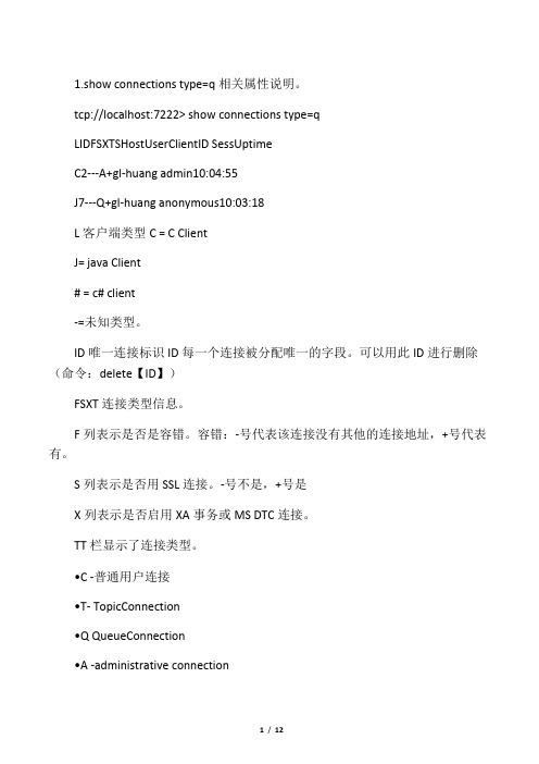
1.show connections type=q相关属性说明。
tcp://localhost:7222> show connections type=qLIDFSXTSHostUserClientID SessUptimeC2---A+gl-huang admin10:04:55J7---Q+gl-huang anonymous10:03:18L客户端类型C = C ClientJ= java Client# = c# client-=未知类型。
ID唯一连接标识ID每一个连接被分配唯一的字段。
可以用此ID进行删除(命令:delete【ID】)FSXT连接类型信息。
F列表示是否是容错。
容错:-号代表该连接没有其他的连接地址,+号代表有。
S列表示是否用SSL连接。
-号不是,+号是X列表示是否启用XA事务或MS DTC连接。
TT栏显示了连接类型。
•C -普通用户连接•T- TopicConnection•Q QueueConne ction•A -administrative connection•R——系统连接到另一条路服务器•F)——系统连接到容错服务器S连接状态+已经启动–已经停止Sess在这个数量上并发连接Uptime已连接时长2.show queues相关属性说明QueueNameSNFGXIBCTPreRcvrsMsgsSize>---------5*000.0 Kb$sys.admin+--------5*000.0 Kb$sys.lookup---------5*000.0 Kb$sys.redelivery.delay+--------5*000.0Kb$sys.undelivered+--------5*000.0 Kb$TMP$.EMS-SERVER.32004D5A3D751555.1---------510 0.0 Kbqueue.sample---------5*000.0 Kbsample---------5*000.0 Kbsample.Q1---------5*000.0 Kbsample.Q2---------5*0996120.3 KbtestSample.Q1---------5*000.0 Kbshow queues关键参数说明:SNFGXIBCTS是否安全。
