AN-1101_SCALE-2门极驱动核的应用指南_2013_09_20_CN
演示文稿1
门极驱动电流的计算
- 门极电流由门极驱动电压和门极电阻决定 - 门极电阻由IGBT芯片或等于IGBT模块内置电阻,加上外置门极驱动电阻 - 开通和关断的峰值门极驱动电流通过公式计算 Imax=△V/(Rinternal+Rexternal) Rinternal=1,7Ω Rexternal= 3,3Ω Imax =30V/(1,7Ω+3,3Ω) Imax =6A
:即插即用, 自动箝位, 2电平和3电平拓扑
电平选择
: Jumper套接 J1 J1中连接1-2 =2电平模式 J1中连接2-3 =3电平模式或多电平模式
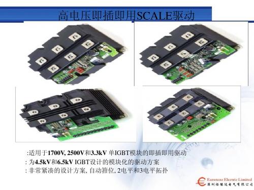
高压即插即用驱动1SD210F2系列
: 适用于6.5kV IGBT的标准化驱动方案 : 即插即用, 自动箝位, 2电平和3电平拓扑
高压即插即用驱动1SD210F2系列
SCALE-2 IGBT 即插即用驱动
: 2SP0320 : PrimePACK™门极驱动 : 门极电压: +15V regulated, -10V : 最大开关频率15kHz : 最大DC-连接电压1200V/1700V : 传输延迟时间小于100ns : 3.3V … 15V逻辑兼容 : 延迟波动小于1.2ns : 工作温度 –40°C … 85°C : 便于PrimePACK™的并联
: ± 8A门极电流和2 x 1W的驱动功率 : 高度集成:相对于离散的形式减少了 超过85%的组件数量 : 易于并联 : 杰出的性能,稳定性,低损耗 : 20US$ 基于10K pcs.的价格
: 2SC0435T : 双通道的1200V和1700V 低损耗IGBT驱动 : SCALE-2技术 : 现有的全世界最小的 35A/1700V驱动内核 : ± 35A门极电流和 2 x 4W驱动功率 : 高度集成:相对于离散的 式减少了超过85%的组 件数量 : 易于并联 : 杰出的性能,稳定性,低损耗 : 将在2010年第一季度上市
CC1101中文资料
单片低成本低能耗RF收发芯片应用z极低功率UHF无线收发器z315/433/868和915MHz ISM/SRD波段系统z AMR-自动仪表读数z电子消费产品z RKE-两路远程无键登录z低功率遥感勘测z住宅和建筑自动控制z无线警报和安全系统z工业监测和控制z无线传感器网络产品介绍CC1100是一种低成本真正单片的UHF收发器,为低功耗无线应用而设计。
电路主要设定为在315、433、868和915MHz的ISM(工业,科学和医学)和SRD(短距离设备)频率波段,也可以容易地设置为300-348 MHz、400-464 MHz和800-928 MHz的其他频率。
RF收发器集成了一个高度可配置的调制解调器。
这个调制解调器支持不同的调制格式,其数据传输率可达500kbps。
通过开启集成在调制解调器上的前向误差校正选项,能使性能得到提升。
CC1100为数据包处理、数据缓冲、突发数据传输、清晰信道评估、连接质量指示和电磁波激发提供广泛的硬件支持。
CC1100的主要操作参数和64位传输/接收FIFO(先进先出堆栈)可通过SPI接口控制。
在一个典型系统里,CC1150和一个微控制器及若干被动元件一起使用。
CC1100基于0.18微米CMOS晶体的Chipcon的SmartRF 04技术。
主要特性z体积小(QLP 4×4mm封装,20脚)z真正的单片UHF RF收发器z频率波段:300-348 MHz、400-464 MHz 和800-928 MHzz高灵敏度(1.2kbps下-110dBm,1%数据包误差率)z可编程控制的数据传输率,可达500kbpsz较低的电流消耗(RX中15.6mA,2.4kbps,433MHz)z可编程控制的输出功率,对所有的支持频率可达+10dBm z优秀的接收器选择性和模块化性能z极少的外部元件:芯片内频率合成器,不需要外部滤波器或RF转换z可编程控制的基带调制解调器z理想的多路操作特性z可控的数据包处理硬件z快速频率变动合成器带来的合适的频率跳跃系统z可选的带交错的前向误差校正z单独的64字节RX和TX数据FIFOz高效的SPI接口:所有的寄存器能用一个“突发”转换器控制长沙云宝电子科技有限公司z 数字RSSI 输出z 与遵照EN 300 220(欧洲)和FCCCFR47 Part 15 (美国)标准的系统相配 z 自动低功率RX 拉电路的电磁波激活功能z 许多强大的数字特征,使得使用廉价的微控制器就能得到高性能的RF 系统 z 集成模拟温度传感器z 自由引导的“绿色”数据包 z 对数据包导向系统的灵活支持:对同步词汇侦测的芯片支持,地址检查,灵活的数据包长度及自动CRC 处理 z 可编程信道滤波带宽 z OOK 和灵活的ASK 整型支持 z 2-FSK ,GFSK 和MSK 支持z 自动频率补偿可用来调整频率合成器到接收中间频率z 对数据的可选自动白化处理z 对现存通信协议的向后兼容的异步透明接收/传输模式的支持 z 可编程的载波感应指示器z 可编程前导质量指示器及在随机噪声下改进的针对同步词汇侦测的保护 z 支持传输前自动清理信道访问(CCA ),即载波侦听系统z 支持每个数据包连接质量指示z1 缩写词资料中用到的缩写词如下: 2-FSK 2进制频率转换按键 ADC 模数转换器 AFC 自动频率补偿 AGC 自动增益控制 AMR 自动仪表读取 ASK 振幅转换按键 BER 位误差率CCA 清理信道评估 CRC 循环冗余检查EIRP 等价等方性的辐射功率 ESR 等价串联阻抗 FEC 前向误差校正 FIFO 先进先出堆栈 FSK 频移键控GFSK 高斯整形频率转换键控 IF 中间频率LBT 发送之前侦测 LNA 低噪声放大器 LO 局部振荡器LQI 链接质量指示器MCU 微控制器单元 MSK 最小化转换按键 PA 功率放大器 PCB 印制电路板 PD 功率降低PQI 前导质量指示器 PQT 前导质量门限 RCOSC RC 振荡器 RF 电磁波频率RSSI 接收信号长度指示器 RX 接收,接收模式 SAW 接口水波 SNR 信噪比SPI 连续外围接口 TBD 待定义TX 发送,发送模式 VCO 电压控制振荡器WOR 电磁波激活,低功率拉电路 XOSC 石英晶体振荡器 XTAL 石英晶体目录1 缩写词 (2)2 工作条件 (6)3 电气规范 (6)4 常规特性 (7)5 RF接收环节 (8)6 RF传输环节 (9)7 石英晶体振荡器 (9)8 低功率RC振荡器 (10)9 频率合成器特性 (10)10 模拟温度传感器 (11)11 直流特性 (11)12 重启功率 (11)13 引脚结构 (12)14 电路描述 (13)15 应用电路 (14)16 结构配置概述 (15)17 配置软件 (16)18 4线串行配置和数据接口 (17)18.1 芯片状态位 (17)18.2 寄存器访问 (18)18.3 命令滤波 (18)18.4 FIFO访问 (18)18.5 PATABLE访问 (19)19 微控制器接口和引脚结构 (20)19.1 配置接口 (20)19.2 常规控制和状态引脚 (20)19.3 可选通信控制特性 (21)20 数据率设计 (21)21 接收信道滤波带宽 (21)22 解调器,符号同步装置和数据决定 (22)22.1 频率便宜补偿 (22)22.2 位同步 (22)22.3 字节同步 (22)23 数据包处理和硬件支持 (23)23.1 数据白化 (23)23.2 数据包格式化 (23)23.3 接收模式下的数据包滤波 (25)23.4 传输模式下的数据包处理 (25)23.5接收模式下的数据包处理 (25)24 调制格式化 (26)24.1 频率转换按键 (26)24.2 相位转换按键 (26)24.3 振幅调制 (26)25 已接收信号质量和连接质量信息 (26)25.1 前导质量门限(PQT) (26)25.2 RSSI (26)25.3 载波感应(CS) (27)25.4 清理信道访问(CCA) (27)25.5 连接质量指示(LQI) (27)26 交错前向误差校正 (27)26.1 前向误差校正(FEC) (27)26.2 交错 (28)27 通信控制 (29)27.1 开启顺序功率 (29)27.2 晶体控制 (30)27.3 电压调节控制 (30)27.4 主动模式 (30)27.5 电磁波激活(WOR) (31)27.5.1 RC振荡器和定时 (31)27.6 定时 (32)27.7 RX终止定时器 (32)28 数据FIFO (33)29 频率控制 (34)30 VCO (34)30.1 VCO和PLL自校准 (34)31 电压调节 (34)32 输出功率调节 (35)33 晶体振荡器 (36)34 天线接口 (36)35 常规用途/测试输出控制引脚 (37)36 异步和同步连续操作 (38)36.1 异步操作 (38)36.2 同步连续操作 (39)37 配置寄存器 (39)37.1配置寄存器详情-休眠状态下带保存值的寄存器 (43)37.2配置寄存器详情-休眠状态下失去控制的寄存器 (53)37.3状态寄存器详情 (54)38 安装描述(QLP20) (56)38.1 推荐安装PCB设计(QLP20) (57)38.2 安装发热特性 (57)38.3 焊接信息 (57)38.4 盘规格 (57)38.5 载波带和轴规范 (57)39 分类信息 (58)40 总体信息 (58)40.1 文件历史 (58)40.2 产品状况定义 (58)40.3 不予承诺的内容 (58)40.4 商标 (58)40.5生命支持政策 (59)41 地址信息 (60)1 绝对最大等级任何条件下都不可违反表1给出的绝对最大等级。
高速MOSFET门极驱动电路的设计应用指南(有图完整版)
高速MOSFET门极驱动电路的设计应用指南author Laszlo Baloghtranslator Justin Hu摘要本文主要演示了一种系统化的方法来设计高速开关装置的高性能门极驱动电路。
文章收集了大量one-stop-shopping 主题的信息来解决最普通的设计挑战。
因此它应当对各种水平的电力电子工程师都适用。
最常用的电路方案和它们的性能都经过了分析,包括寄生参数、瞬时和极端运行条件的影响。
文章首先回顾了MOSFET技术和开关运行模式,然后由简入繁地讨论问题。
详细的描述了参考地和高端门极驱动电路的设计程序、交流耦合和变压器隔离方案。
专门的一章用来介绍同步整流装置中MOSFET的门极驱动要求。
文章另举出了几个设计的实例,一步一步进行了说明。
Ⅰ.引言MOSTET是金属氧化物半导体场效应晶体管(Metal Oxide Semiconductor Field Effect Transistor)的缩写,是电子工业中高频、高效率开关装置的关键器件。
令人惊叹的是,场效应晶体管技术发明于1930年,比双极性晶体管早了大约20年。
第一个信号级别的场效应晶体管20世纪50年代末期被制造出来,功率级别的MOSFET在20世纪70年代中期出现。
而今天无数的MOSFET被集成到现代电子器件中,无论是微处理器还是分立的功率晶体管。
本文所关注的是功率MOSFET在各种各样的开关模式功率变换器装置中门极驱动的要求。
Ⅱ.MOSFET技术双极型和MOSFET晶体管都使用了同样的工作原理。
从根本上讲,这两种晶体管都是电荷控制的器件,这就意味着它们的输出电流和控制电极在半导体中建立的电荷成比例。
当这些器件用作开关时,它们都必须被一个低阻抗的电源驱动,电源要能提供足够的充放电电流来使它们快速建立或释放控制电荷。
从这一点来看,MOSFET在开关过程中必须和双极性晶体管一样通过“硬”驱动才能获得类似的开关速度。
理论上,双极型和MOSFET器件的开关速度几乎一样,由载流子运动经过半导体区域所需要的时间决定。
FTA1101 用户手册说明书
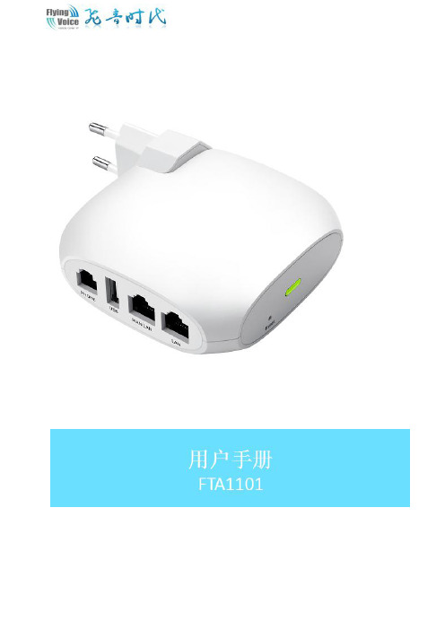
目录关于本指南 (4)目的 (6)交叉引用 (6)反馈 (6)产品符合声明 (7)CE认证 (7)FCC认证 (7)B类数字设备或周边设备 (7)操作安全要则 (8)警告和注意事项 (9)警告 (9)注意事项 (9)第1章产品介绍 (10)FTA1101 (11)指示灯和接口 (12)接口介绍 (12)硬件安装 (13)安装准备 (13)安装步骤 (13)第2章IVR(互动式语音应答) (14)配置设备的方法(IVR) (15)启动IVR (15)IVR描述 (15)第3章基本配置 (18)WEB页面 (19)URL格式 (19)关于密码 (20)Web界面 (20)账号配置 (22)基本功能 (23)拨打电话 (23)IP直拨 (23)呼叫保持 (23)呼叫转移 (23)呼叫等待 (24)三方会议 (24)速拨 (25)热线 (25)第4章Web界面管理 (26)登录 (27)状态 (28)系统信息 (28)内网主机信息 (28)系统日志 (29)网络 (30)WAN口设置 (30)LAN口设置 (35)IPv6设置 (36)VPN设置 (39)端口映射 (41)DMZ (42)DDNS (42)端口管理 (43)路由配置 (43)高级设置 (44)Eoip隧道 (45)无线设置 (46)基本设置 (46)无线安全 (48)Wi-Fi多媒体(WMM) (51)无线分布式部署(WDS) (51)Wi-Fi保护设置(WPS) (51)无线客户端(Station Info) (53)高级设置 (53)VOIP (55)账号设置 (55)SIP设置 (60)VoIP QoS (61)电话 (62)首选项 (62)数图 (66)黑名单 (67)通话日志 (68)管理 (70)管理 (70)固件升级 (73)计划任务 (74)自动跟新(Provision) (75)SNMP (76)TR069 (77)诊断 (78)工作模式 (79)第5章故障排除 (80)接通电源后无反应 (81)无法登录设备的网页 (81)忘记密码 (81)FTA1101家庭网关是一个高集成度的综合接入设备,是一款集路由和VoIP于一体的无线路由设备。
2SC0435T_Manual_2014-04-03_CN

图1与应用手册
目录
摘要 ................................................................................................................................................. 1 目录 ................................................................................................................................................. 2 驱动器概述 ....................................................................................................................................... 4 机械尺寸........................................................................................................................................... 5 管脚定义........................................................................................................................................... 7 原方接口的推荐电路 .......................................................................................................................... 8 原方接口电路描述 .............................................................................................................................. 8
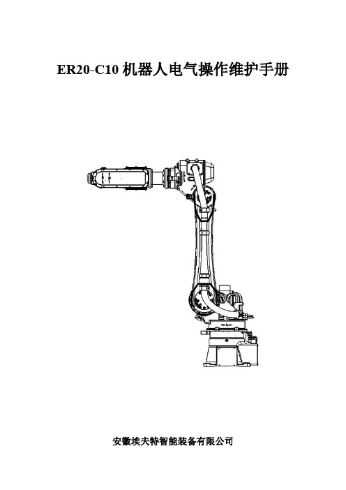
ER20-C10 机器人电气操作维护手册20130419
安徽埃夫特智能装备有限公司
ER20-C10 机器人电气操作维护手册
目录
1 安全注意事项.............................................................................................................................. 1 1.1 机器人安全使用须知....................................................................................................... 1 1.1.1 操作调试机器人时的安全注意事项.................................................................... 1 1.1.2 机器人本体的安全对策........................................................................................ 3 1.1.3 试车安全对策........................................................................................................ 5 1.1.4 自动运转的安全对策............................................................................................ 5 1.2 以下场合不可使用机器人............................................................................................... 6 1.3 安全操作规程................................................................................................................... 6
SP-1101W SP-2101W 快速装置指南说明书
SP-1101W/SP-2101Wrmations sur le produit I-1. Contenu de l'emballageI-2. Panneau avantVoyant réseauVoyant Alimentation Bouton et voyant d'état de l'interrupteurBouton deréinitialisationPrise intelligente commutée Guide d'installation rapide CD avec guided'installation rapideI-3. État du voyantafin que l'application EdiPlug fonctionne de façon déportée, c'est-à-dire à partir d'une connexion Internet différente de celle de votre prise intelligente.I-4.Bouton d'état de l'interrupteurLe bouton d'état de l'interrupteur, situé en façade de votre prise intelligente (voir I-2.), permet de mettre en marche/arrêter la sortie d'alimentation de votre prise intelligente. Vous pouvez mettre en marche/arrêter n'importe quel appareil branché dans votre prise intelligente avec ce bouton. Le bouton s'allume en vert pour indiquer marche (voir I-3).l'interrupteurAlimentationRéseauI-5. Étiquette du produitL'étiquette du produit se trouve à l'arrière de la prise intelligente commutée et indique la puissance d'entrée/sortie ainsi que le mot de passe par défaut de votre prise intelligente. Pour des raisons de sécurité, vous devez modifié le mot de passe une fois l'installation terminée. Le mot de passe est nécessaire pour accéder à la prise intelligente commutée à distance.I-6. RéinitialiserSi vous rencontrez des problèmes avec votre priseintelligente, vous pouvez le réinitialiser avec lesparamètres d'usine par défaut. Cela réinitialisetous les paramètres aux valeurs par défaut, ycompris le mot de passe de la prise intelligente.1.Maintenez enfoncé le bouton deréinitialisation à l'avant de la prise intelligentependant au moins 10 secondes2.Relâchez le bouton lorsque le voyant réseauclignote rapidement en rouge.3.Attendez que la prise intelligente redémarre.La prise est prête lorsque le voyant réseau clignote lentement en rouge pour indiquer le mode Installation.II.Installation matérielleRespectez les instructions ci-dessous pour garantir que votre prise intelligente est correctement branchée et prête pour la configuration.Si vous devez configurer plusieurs prises intelligentes, ne branchezet ne configurez qu'une seule prise intelligente à la fois.1.Branchez la prise intelligente dans une prise de courant.2.Patientez quelques instants que la prise intelligente démarre. La priseintelligente est prête pour la configuration lorsque le voyant réseauclignote lentement en rouge pour indiquer le mode Installation.Si le voyant Réseau de votre prise intelligente n'indique pas lemode Installation, essayez de réinitialiser la prise intelligente(voir I-6).3.Lorsque le voyant Réseau de la prise intelligente indique le modeInstallation, passez à la section III. Configuration de la prise intelligente pour configurer votre prise intelligente à l'aide de l'application gratuite pour smartphone EdiPlug.III.Configuration de la prise intelligentePour configurer votre prise intelligente avec l'application pour smartphone EdiPlug, veuillez télécharger l'application EdiPlug et suivre les instructionsd'installation pour iOS ou Android. Après l'installation, vous pouvez utiliser l'application EdiPlug pour mettre en marche/arrêter votre prise intelligente à distance depuis n'importe quel smartphone avec une connexion à Internet et configurer la planification automatique et les notifications par e-mail.1.Dans la boutique Apple App Store ou Google Play, recherchez « EdiPlug ».2.Téléchargez et installez l'application.3.Suivez les instructions appropriées ci-dessous pour iOS ou Android.III-1. iOSSuivez les instructions ci-dessous pour ajouter une nouvelle prise intelligente à l'application EdiPlug sur iOS :Vous devez vous trouver dans la portée Wi-Fi de la priseintelligente. Si vous disposez de plusieurs prises intelligentes, nebranchez et ne configurez qu'une seule prise à la fois.1.Recherchez et connectez-vous au réseau Wi-Fi appelé « EdiPlug.Setup »,comme indiqué ci-dessous :2.Ouvrez l'application EdiPlug et sélectionnez votre réseau Wi-Fi dans la liste,comme indiqué ci-dessous :3.Entrez votre mot de passe Wi-Fi et appuyez sur "OK" puis patientez letemps que votre prise redémarre.4.L'écran suivant indique que la configuration est terminée. Votre priseintelligente est alors affichée sur l'écran principal d'EdiPlug. Appuyez sur l'interrupteur pour mettre en marche ou arrêter votre prise intelligente (et n'importe quel appareil électrique qui y est branché).5.Le voyant réseau de la prise intelligente doit être allumé et vert pourindiquer une connexion réussie au réseau et au Cloud. Vous pouvez utiliser l'application EdiPlug pour contrôler votre prise intelligente à distance,depuis n'importe quelle connexion à Internet.III-1-1. Changer le nom et le mot de passe de la prise intelligente1.Sélectionnez « Éditer » sur l'écran principal d'EdiPlug, puis sélectionnez,dans la liste, la prise intelligente que vous voulez éditer.2.Saisissez un nouveau nom et un nouveau mot de passe pour votre priseintelligente et appuyez sur « Retour » pour revenir à l'écran principal. Votre prise intelligente est alors affichée avec son nouveau nom.Les fonctionnalités comme la programmation, le contrôle dubudget et les notifications par email peuvent également êtreconfigurées dans le menu "Paramètres Prise".III-1-2. Ajouter une prise intelligente existante à l'écran principal1.Dans l'écran principal d'EdiPlug, cliquez sur l'icône « + » en haut à droite etsélectionnez une prise dans la liste.2.Saisissez le mot de passe de votre prise intelligente et appuyez sur « OK ».Cliquez sur l'icône à cocher à côté du nom de votre prise sur l'écran qui suit pour terminer.Le mot de passe par défaut est 123410 III-2. AndroidSuivez les instructions ci-dessous pour ajouter une nouvelle prise intelligente à l'application EdiPlug sur Android :Vous devez vous trouver dans la portée Wi-Fi de la priseintelligente. Si vous disposez de plusieurs prises intelligentes, nebranchez et ne configurez qu'une seule prise à la fois. 1. Ouvrez l'application EdiPlug et cliquez sur l'icône « + » en haut à droite del'écran.2. Appuyez sur « Installer une nouvelle prise » et sélectionnez votre réseauWi-Fi dans la liste, comme indiqué ci-dessous.113. Entrez votre mot de passe Wi-Fi et appuyez sur "OK" puis patientez letemps que votre prise redémarre.4. L'écran suivant indique que la configuration est terminée. Cliquez sur"Suivant" et votre prise intelligente est alors affichée sur l'écran principal d'EdiPlug. Appuyez sur l'interrupteur pour mettre en marche ou arrêter votre prise intelligente (et n'importe quel appareil électrique qui y estbranché).5. Le voyant réseau de la prise intelligente doit être allumé et vert pour indiquer une connexion réussie au réseau et au Cloud. Vous pouvez utiliser l'application EdiPlug pour contrôler votre prise intelligente à distance depuis n'importe quelle connexion à Internet.12 III-2-1.Changer le nom et le mot de passe de la prise intelligente 1. Sélectionnez « Éditer » sur l'écran principal d'EdiPlug, puis sélectionnez,dans la liste, la prise intelligente que vous voulez éditer.2. S aisissez un nouveau nom et un nouveau mot de passe pour votre prise intelligente et appuyez sur « Retour » pour revenir à l'écran principal. Votre prise intelligente est alors affichée avec son nouveau nom.Les fonctionnalités comme la programmation, le contrôle dubudget et les notifications par email peuvent également êtreconfigurées dans le menu "Paramètres Prise ".13 III-2-2. Ajouter une prise intelligente existante à l'écran principal 1. Dans l'écran principal d'EdiPlug, cliquez sur l'icône « + » en haut à droite etsélectionnez une prise dans la liste.2. Saisissez le mot de passe de votre prise intelligente et appuyez sur « OK ». Cliquez sur l'icône à cocher à côté du nom de votre prise sur l'écran qui suit pour terminer.Le mot de passe par défaut est 1234。
英飞凌驱动板功能介绍

简介
SCALE-2 IGBT 和 MOSFET 驱动核由低成本元件高度集成,为用户提供了最好的技术和功 能来满足工业和牵引的要求。SCALE-2 的这些特点,以及设计的灵活性,已经使很多功 率变换器性能良好。然而,SCALE-2 门极驱动核不是即插即用的门极驱动,因此,我们 需要稍微了解一下功率电力电子器件,以使应用这类驱动核的逆变系统更可靠。 本应用说明将突出重要的设计规则,帮助使用者避免质量问题。此外,它给出了详细的 门极驱动核设计实例,大大缩短了驱动核设计时间。 SCALE-2 门极驱动核主要包括以下型号:2SC0106T,2SC0108T,2SC0435T,2SC0650P, 1SC2060P,2SC0535T,2SC0635T 以及 1SC0450V。
直接并联
并联连接的 IGBT 一般由一个共同的驱动器驱动, 驱动器给每个 IGBT 提供单独的门 极驱动信号和发射极电阻。另一个驱动并联的 IGBT 模块的方法是给每个模块提供分别 的驱动,目前本应用手册中所有的具有电气接口的驱动核都可以实现这一功能。 如果需要 SCALE-2 直接并联,请参考应用手册 AN-0904。
单个 SCALE-2 门极驱动驱动并联的 IGBT/MOSFET
单个驱动核驱动多个并联的 IGBT 时的高级有源钳位 有源钳位技术的作用是,当集-射(漏-源)极电压超过预设的阈值电压时部分开通 器件,然后功率器件保持工作在线性区。 基本的有源钳位技术仅采用了一个反馈回路, , 从 IGBT 的集电极经过暂态电压抑制 器(TVS)到 IGBT 的门极。大部分 SCALE-2 产品支持高级有源钳位功能,从图 3 中可以 看出, 信号反馈到驱动器二次侧 ACLx 脚处: 只要图中右侧的 20Ω 电阻的电压超过 1.3V, 驱动级的 MOSFET 就会逐渐关断,这样可以提高高级有源钳位的效率,减少了 TVS 的损 耗。当右侧的 20Ω 电阻的电压超过 20V(以 COMx 为参考) ,那么 MOSFET 就被完全关 断。在单个驱动核驱动多个并联的 IGBT/MOSFET 的应用中,高级有源钳位需要控制所 有并联连接的 IGBT/MOSFET,这样就需要根据图 3 给每个门极提供单独的反馈。
2SC0435T_Manual_2013-02-21_CN

概述 .................................................................................................................................... 12 DC/DC 输出(VISOx)、发射极(VEx)和 COMx 端子 .................................................................... 12 参考端子(REFx) ................................................................................................................... 12 集电极电位检测端子(VCEx) .................................................................................................. 12 有源钳位(ACLx) ................................................................................................................... 13 门极开通(GHx)和门极关断(GLx)端子 ..................................................................................... 14
2SC0435T SCALE-2 驱动器的详细工作原理...................................................................................... 14
828D简明调试手册_2019 4.8 SP4
滚筒烘干机操作手册说明书

TMB1277C_SVG
产品编号 70457901CNR18 4 月 2019
产品安装时必须遵守本地法规,如本地无相关法规,则: 在美国,应遵守美国国家标准 Z223.1/ NFPA 54 《国家燃气规范》(National Fuel Gas Code) 的最新版本以及标准 ANSI/NFPA 70《国家电气安全规范》(National Electric Code)。 在加拿大,应遵守 CAN/CSA-B149.1 即《天然气和丙烷安装规范》(Natural Gas and Propane Installation Code) 以及最新版本 的 CSA C22.1 《加拿大电气标准》(Canadian Electric Code) 的第一部分。 在澳大利亚及新西兰,应遵守燃气安装标准 AS/NZS 5601 第一部分“一般安装方法”(General Installations) 中的规定。
W002R1ຫໍສະໝຸດ ©Alliance Laundry Systems LLC,版权所有 – 请勿复制或传播
3
产品编号 70457901CNR18
警告
• 设备必须由合格安装人员进行安装。 • 安装滚筒烘干机时必须遵守制造商的说明和当地有关法规。 • 请勿使用柔性塑料通风材料安装滚筒烘干机。如果安装了柔性金属(箔式)管道,该管道必须属于经设备制造商认可
尺寸规格...............................................................................................16 尺寸规格..................................................................................................... 16 机体尺寸..................................................................................................... 18 排气口位置................................................................................................. 19 燃气连接位置.............................................................................................. 20 电气连接位置.............................................................................................. 21 蒸汽连接位置.............................................................................................. 22
IGBT智能化驱动板SCALE

IGBT智能化驱动板SCALE摘要:SCALE驱动是瑞士Concept公司生产的IGBT智能化驱动板,可用于驱动和保护IGBT。
文中介绍了该IGBT智能化驱动板的主要功能、工作模式和引脚功能,给出该器件的典型应用电路。
关键词:IGBT;驱动模块;SCALE1概述由于IGBT(绝缘栅双极性晶体管)是一种电压控制型功率器件,它所需驱动功率小,控制电路简单,导通压降低,且具有较大的安全工作区和短路承受能力。
因此,目前IGBT已在中功率以上的电力电子系统中(如变频器、UPS电源、高频焊机等)逐渐取代了POWERMOSFET及POWERBJT而成为功率开关元件市场中的重要一员。
然而 如何有效地驱动并保护IGBT则成为目前电力电子领域中的重要研究课题之一。
一个具有保护功能的驱动电路不但能在正常工作状态下给IGBT提供所需的驱动功率,在异常工作状态下能起保护IGBT的作用,而且应当能使电力电子系统中的IGBT有很好的替换特性。
因此 高性能的驱动电路是提高电子产品品质和可靠性,从而增强其竞争力的关键之一。
本文介绍一种高性能、智能化的IGBT驱动板SCALE。
图12功能介绍SCALE驱动板系列是瑞士Concept公司生产的,Concept公司是专业生产IGBT驱动电路的公司,主要为西门子/EUPEC高压大电流IGBT模块配套。
该SCALE驱动板采用ASIC设计,仅用15V电源驱动,开关频率可大于100kHz,且具有高可靠和长寿命特性,可驱动1700V、1200A的IGBT。
1998年度赢得ABB优秀电力电子项目称号,其主要型号和驱动能力如表1所列。
表1 SCALE的主要型号和驱动能力2.1SCALE的特点●实用范围宽 可应用在数千瓦至数兆瓦的功率范围及实用的耐压要求范围内,几乎可工作在所有的频率及调制模式,适用于任何厂家的模块。
●体积小巧、结构紧凑、应用灵活,具有直接和半桥模式可供选择。
在半桥模式下,可选用所要求的死区时间。
LT1101CN8#PBF,LT1101ACN8#PBF,LT1101AIN8#PBF,LT1101CN8,LT1101SW,LT1101SW#TR, 规格书,Datasheet 资料

1芯天下--/2芯天下--/31101faLT1101AM/AI/AC LT1101M/I/C SYMBOL PARAMETER CONDITIONSMIN TYP MAXMIN TYP MAXUNITSG EGain ErrorG = 100, V O = ±10V, R L = 50k 0.0080.0400.0090.060%G = 100, V O = ±10V, R L = 2k0.0110.0550.0120.070%G = 100, V O = ±10V, R L = 50k or 2k 0.0080.0400.0090.060%G NLGain NonlinearityG = 100, R L = 50k 716820ppm G = 100, R L = 2k24452560ppm G = 10, R L = 50k or 2k 3839ppm V OS Input Offset Voltage 5016060220µV LT1101SW250600µV l OS Input Offset Current 0.130.600.150.90 nA I BInput Bias Current 68610nA Input Resistance Common Mode (Note 2)4737G ΩDifferential Mode(Note 2)712512G Ωe nInput Noise Voltage 0.1Hz to 10Hz (Note 3)0.9 1.80.9µVp-p Input Noise Voltage f O = 10Hz (Note 3)456445nV/√Hz Densityf O = 1000Hz (Note 3)435443nV/√Hz i nInput Noise Current 0.1Hz to 10Hz (Note 3) 2.3 4.0 2.3pAp-p Input Noise Current f O =10Hz (Note 3)0.060.100.06pA/√Hz Densityf O = 1000Hz 0.020.02pA/√Hzlnput Voltage RangeG = 10013.013.813.013.8V –14.4–14.7–14.4–14.7V G = 1011.512.511.512.5V –13.0–13.3–13.0–13.3V CMRRCommon Mode 1k Source Imbalance Rejection Ratio G = 100, Over CM Range 10011298112dB G = 10, Over CM Range 841008299dB PSRR Power Supply V S = +2.2V, –0.1V to ±18V102114100114dB Rejection Ratio I SSupply Current9213094150µAELECTRICAL CHARACTERISTICSLT11O1AM/AI/AC LT1101M/I/C SYMBOL PARAMETER CONDITIONSMIN TYP MAX MIN TYP MAX UNITS CMRRCommon Mode 1k Source ImbalanceRejection Ratio G = 100, V CM = 0.07V to 3.4V 9510692105 dB G = 10, V CM = 0.07V to 3.1V 841008299 dB Minimum Supply Voltage(Note 5)1.82.31.82.3V V OMaximum 0utput Output High, 50k to GND 4.1 4.3 4.1 4.3 V Voltage SwingOutput High, 2k to GND3.53.9 3.53.9 V Output Low, V REF = 0, No Load 3.36 3.36mV Output Low, V REF = 0, 2k to GND 0.510.51mV Output Low, V REF = 0, l SINK = 100µA 9013090130mV BW Bandwidth G = 100 (Note 2) 2.0 3.0 2.0 3.0kHz G = 10 (Note 2)22332233kHz SRSlew Rate(Note 2)0.040.070.040.07V/µsV S = 5V, 0V, V CM = 0.1V, V REF(PIN 1) = 0.1V, G = 10 or 100, T A = 25°C, unlessotherwise noted. (Note 4)V S = ±15V, V CM = 0V, T A = 25°C, Gain = 10 or 100, unless otherwise noted.芯天下--/41101faELECTRICAL CHARACTERISTICSLT1101AM/AI LT1101M/I SYMBOL PARAMETER CONDITIONS MIN TYP MAX MIN TYP MAX UNITSV O Maximum 0utput R L = 50k 13.014.213.014.2V Voltage Swing R L = 2k 11.013.211.013.2V BW Bandwidth G = 100 (Note 2) 2.3 3.5 2.3 3.5kHz G = 10 (Note 2)25372537kHz SRSlew Rate0.060.100.060.10V/µsV S = ±15V, V CM = 0V, T A = 25°C, Gain = 10 or 100, unless otherwise noted.LT1101AM/AI LT1101M/I SYMBOL PARAMETER CONDITIONSMIN TYP MAXMINTYP MAX UNITSG EGain ErrorG = 100, V O = ±10V, R L = 50k 0.0240.0700.0260.100%G = 100, V O = ±10V, R L = 5k0.0300.1000.0350.130%G = 10, V O = ±10V, R L = 50k or 5k 0.0150.0700.0180.100%TCG EGain Error Drift G = 100, R L = 50k 2425ppm/°C (Note 2)G = 100, R L = 5k2728ppm/°C G = 10, R L = 50k or 5k 1415ppm/°C G NLGain NonlinearityG = 100, R L = 50k 24702690ppm G = 100, R L = 5k 7030075500ppm G = 10, R L = 50k 413515ppm G = 10, R L = 5k 10401260ppm V OSInput Offset Voltage90350110500µV LT1101ISW110950µV ∆V OS /∆T Input Offset Voltage Drift (Note 2)0.4 2.00.5 2.8µV/°C LT1101ISW0.5 4.8mV/°C l OS Input Offset Current 0.160.800.19 1.30 nA ∆l OS /∆T Input Offset Current Drift (Note 2)0.5 4.00.87.0pA/°C I B Input Bias Current 710712 nA ∆I B /∆T Input Bias Current Drift (Note 2)10251030pA/°C CMRR Common Mode G = 100, V CM = –14.4V to 13V 9611194111dB Rejection Ratio G = 100, V CM = –13V to 11.5V 80997898dB PSRR Power Supply V S = 3.0, –0.1V to ±18V9811094110dB Rejection Ratio I S Supply Current 105165108190µA V OMaximum 0utput R L = 50k 12.514.012.514.0V Voltage SwingR L = 5k11.013.511.013.5VELECTRICAL CHARACTERISTICSV S = ±15V, V CM = 0V, Gain = 10 or 100, –55°C ≤ T A ≤ 125°C for AM/Mgrades, –40°C ≤ T A ≤ 85°C for AI/I grades, unless otherwise noted.芯天下--/ELECTRICAL CHARACTERISTICS VS = ±15V, V CM = 0V, Gain = 10 or 100, 0°C ≤ T A≤ 70°C, unless otherwise noted.LT1101AC LT1101C/SSYMBOL PARAMETER CONDITIONS MIN TYP MAX MIN TYP MAX UNITS G E Gain Error G = 100, V O = ±10V, R L = 50k0.0120.0550.0140.080%G = 100, V O = ±10V, R L = 2k0.0180.0850.0200.100%G = 10, V O = ±10V, R L = 50k or 2k0.0090.0550.0100.080% TCG E Gain Error Drift G = 100, R L = 50k1415ppm/°C (Note 2)G = 100, R L = 2k2729ppm/°CG = 10, R L = 50k or 5k1415ppm/°C G NL Gain Nonlinearity G = 100, R L = 50k9251035ppmG = 100, R L = 2k337536100ppmG = 10, R L = 50k or 2k410411ppm V OS Input Offset Voltage7025085350µVLT1101SW300800µV ∆V OS/∆T Input Offset Voltage Drift(Note 2)0.4 2.00.5 2.8µV/°CLT1101SW 1.2 4.5µV/°C l OS Input Offset Current0.140.700.17 1.10 nA ∆I OS/∆T Input Offset Current Drift(Note 2)0.5 4.00.87.0pA/°C I B Input Bias Current69611 nA ∆I B/∆T Input Bias Current Drift(Note 2)10251030pA/°C CMRR Common Mode G = 100, V CM = –14.4V to 13V9811296112dB Rejection Ratio G = 100, V CM = –13V to 11.5V821008099dB PSRR Power Supply V S = 2.5, –0.1V to ±18V10011297112dB Rejection RatioI S Supply Current98148100170µA V O Maximum 0utput R L = 50k±12.5±14.1±12.5±14.1V Voltage Swing R L = 2k±10.5±13.0±10.5±13.0V51101fa芯天下--/61101faLT1101AM/AI LT1101M/I SYMBOL PARAMETER CONDITIONSMIN TYP MAXMINTYP MAX UNITSG E Gain Error G = 100, V 0 = 0.1V to 3.5V, R L = 50k 0.0260.0800.0280.120%G = 10, V CM = 0.15, R L = 50k 0.0110.0700.0140.100%TCG E Gain Error Drift R L = 50k (Note 2)1415ppm/°C G NL Gain Nonlinearity G = 100, R L = 50k4511048140ppm G = 10, R L = 50k (Note 2)413515ppm V OS Input Offset Voltage90350110500µV LT1101ISW110950µV ∆V OS /∆T Input Offset Voltage Drift (Note 2)0.4 2.00.5 2.8µV/°C LT1101ISW0.5 4.8µV/°C l OS Input Offset Current 0.160.800.19 1.30 nA ∆V OS /∆T Input Offset Current Drift (Note 2)0.5 4.00.87.0pA/°C I B Input Bias Current 710712 nA ∆I B /∆T Input Bias Current Drift (Note 2)10251030pA/°C CMRR Common Mode G = 100, V CM = 0.1V to 3.2V9110588104dB Rejection Ratio G = 10, V CM = 0.1V to 2.9V, V REF = 0.15V80987797dB I S Supply Current 8813592160µA V 0Maximum 0utput Output High, 50k to GND 3.8 4.1 3.8 4.1V Voltage SwingOutput High, 2k to GND3.03.7 3.03.7V Output Low, V REF = 0, No Load4.58 4.58mV Output Low, V REF = 0, 2k to GND 0.7 1.50.7 1.5mV Output Low, V REF = 0, I SINK = 100µA125170125170mVV S = 5V, 0V, V CM = 0.1V, V REF(PIN 1) = 0.1V, Gain = 10 or 100,–40°C ≤ T A ≤ 85°C for AI/I grades, unless otherwise noted (Note 4).ELECTRICAL CHARACTERISTICS芯天下--/71101faLT1101AC LT1101C/S SYMBOL PARAMETER CONDITIONSMIN TYP MAX MIN TYP MAX UNITSG E Gain Error G = 100, V O = 0.1V to 3.5V, R L = 50k 0.0170.0650.0180.095%G = 10, V CM = 0.15V, R L = 50k 0.0100.0600.0120.080%TCG E Gain Error Drift R L = 50k (Note 2)1415ppm/°C G NL Gain Nonlinearity G = 100, R L = 50k258025100ppm G = 10, R L = 50k (Note 2)410411ppm V OS Input Offset Voltage7025085350µV LT1101SW300800µV ∆V OS /∆T Input Offset Voltage Drift (Note 2)0.4 2.00.5 2.8µV/°C LT1101SW1.2 4.5µV/°C l OS Input Offset Current 0.140.700.17 1.10 nA ∆I OS /∆T Input Offset Current Drift (Note 2)0.5 4.00.87pA/°C I B Input Bias Current 69611 nA ∆I B /∆T Input Bias Current Drift (Note 2)10251030pA/°C CMRR Common Mode G = 100, V CM = 0.07V to 3.3V9310590104dB Rejection Ratio G = 10, V CM = 0.07V to 3V, V REF = 0.15V82998098dB I S Supply Current 8012085145µA V OMaximum 0utput Output High, 50k to GND 4.0 4.2 4.0 4.2V Voltage SwingOutput High, 2k to GND3.33.8 3.33.8V Output Low, V REF = 0, No Load 4747mV Output Low, V REF = 0, 2k to GND 0.6 1.20.6 1.2mV Output Low, V REF = 0, I SINK = 100µA100150100150mVV S = 5V, 0V, V CM = 0.1V, V REF(PIN 1) = 0.1V, Gain = 10 or 100,0°C ≤ T A ≤ 70°C, unless otherwise noted (Note 4).ELECTRICAL CHARACTERISTICSNote 1: Absolute Maximum Ratings are those values beyond which the life of a device may be impaired.Note 2: This parameter is not tested. It is guaranteed by design and by inference from other tests.Note 3: This parameter is tested on a sample basis only.Note 4: These test conditions are equivalent to V S = 4.9V, –0.1V,V CM = 0V, V REF(PIN1) = 0V.Note 5: Minimum supply voltage is guaranteed by the power supply rejection test. The LT1101 actually works at 1.8V supply with minimal degradation in performance.芯天下--/8芯天下--/9芯天下--/10芯天下--/11芯天下--/12芯天下--/13芯天下--/14芯天下--/Information furnished by Linear Technology Corporation is believed to be accurate and reliable.However, no responsibility is assumed for its use. Linear Technology Corporation makes no represen-tation that the interconnection of its circuits as described herein will not infringe on existing patent rights.芯天下--/15161630 McCarthy Blvd., Milpitas, CA 95035-7417(408) 432-1900 ●FAX: (408) 434-0507 ● LINEAR TECHNOLOGY CORPORA TION 1989芯天下--/。
2SC0108T 双通道、超紧凑、低成本的 SCALE-2 驱动核 应用手册
Preliminary 2SC0108T应用手册双通道、超紧凑、低成本的SCALE-2驱动核摘要这款基于SCALE-2驱动内核的双通道驱动器集低成本,超紧凑于一身,而且有非常宽的应用范围。
该驱动器专门为要求高可靠性的应用领域而设计。
2SC0108T通常可以驱动600A/1200V或者450A/1700V的IGBT模块(具体要看频率)。
这款驱动器内嵌的并联功能使得它可以支持驱动器的并联(多个驱动器并联在一起),同时,它还支持多电平拓扑应用。
2SC0108T是目前工业应用中最紧凑的驱动核,尺寸为45mm×34.3mm,高度为16mm,这使得客户的设计可以更加紧凑。
图 1 2SC0108T 驱动核Description & Application Manual目录驱动器概述 (3)原方接口的推荐电路 (6)原方接口电路描述 (6)概述 (6)VCC端子 (6)MOD (模式选择) (7)INA, INB (PWM信号输入) (7)SO1, SO2 (状态输出) (8)TB (阻断时间TB的设定端) (8)副方接口的推荐电路 (9)副方接口电路描述 (9)概述 (9)发射极端子 (VEx) (9)参考端子(REFx) (10)集电极检测端子 (VCEx) (10)门极开通(GHx)及门极关断(GLx)端子 (10)有源钳位 (11)2SC0108T是怎样工作的? (11)电源及电气隔离 (11)电源监控 (11)Vce监控/短路保护 (12)2SC0108T并联 (13)三电平或多电平拓扑 (13)用二极管检测IGBT退饱和进行保护 (13)参考文献 (13)信息源:SCALE-2驱动器数据手册 (14)客户定制的SCALE-2驱动器 (14)技术支持 (14)质量 (14)法律声明 (14)其他产品的信息 (15)生产厂商 (15)Preliminary 驱动器概述2SC0108T装备了CONCEPT公司最新的SCALE-2芯片组(1),这是一款低成本的驱动核。
CONCEPT_AN-0904_SCALE-2 门极驱动核的直接并联

SCALE-2 门极驱动核的直接并联介绍传统的IGBT并联方法是由单个驱动器驱动多个IGBT,每个IGBT都有独立的门极和发射极电阻。
另一种并联IGBT模块的驱动方法是,每个模块都使用独立的驱动器。
图1显示传统的、使用单个驱动核的并联方式与SCALE-2驱动核直接并联方式之间的差异。
图1:传统并联(左)与使用变压器接口的独立SCALE-2门极驱动核直接并联三个IGBT模块(右)利用CONCEPT的SCALE-2技术能够直接并联门极驱动器,因为带有变压器接口的SCALE-2驱动器,其信号传输延迟(通常为80ns ±4ns)和延迟抖动(通常<±1-3ns)小且公差范围很窄。
因此,以下带有变压器接口的SCALE-2驱动核可以直接并联,而不会在并联的IGBT模块之间产生过大的电流不平衡:∙2SC0108T∙2SC0435T∙2SC0650P∙1SC2060P2SD300C17不适合直接并联。
本应用指南将简要描述直接并联的优势,并解释在直接并联应用中如何使用SCALE-2驱动核。
直接并联的优势与传统并联方式相比,直接并联IGBT驱动器可获得以下优势:∙优化的开关行为,开关损耗最低∙用户友好、安全而可靠的理念∙可用开关频率不会随着并联IGBT模块数量的增加而降低。
∙不存在门极间耦合,因此不同IGBT门极之间不会发生相互振荡∙流过模块基板的容性等效电流不产生影响∙门极电缆上的电感耦合不产生影响∙利于设备直接并联及后续扩容∙IGBT模块的利用率高,降额幅度小∙设置简单,无混乱的布线在直接并联中如何使用SCALE-2驱动核CONCEPT建议在并联应用中使用SCALE-2驱动核时遵循下面的程序:∙所有驱动器都必须采用相同的硬件配置(门极电阻、退饱和保护、有源箝位、支撑电容…)∙所有并联驱动器的电源电压VCC和VDC(如果可用)必须来自同一电压源,以确保驱动器对称地运行(请参考图2)。
∙所有并联驱动器的输入信号INA和INB必须来自同一逻辑缓冲器(驱动器),以确保延迟差异极小(请参考图2)。
CC1101-CC1190EMK 快速上手指南说明书
CC1101CC1190EMK868SWRU284 March 2011CC1101-CC1190EMK Quick Start GuideOpening the box and using the modules with SmartRF04EB1. Kit Contents2 x CC1101-CC1190EM 2 x Antennas DocumentationThe picture above shows the 869 MHz version of the kit.2. How to Use the ModulesThe CC1101-CC1190 Evaluation Module (EM) boards can be plugged into the SmartRF04EB (EB), which is included in the CC11xxDK. This board lets you control the devices from SmartRF ™ Studio and it can also be used as a development platform.This Quick Start Guide describes how to properly power an EB with a CC1101-CC1190EM and how to control the combo from SmartRF Studio.3. Plug EM into SmartRF04EBInsert the EM into the EB. The connectors will only fit in one position, so that the EM cannot be inserted the wrong way.Handle the EM with care. Observe precautions for handling electrostatic sensitive devices.4a. Apply PowerThe EB can be powered from different sources: USB, Battery or an External Power SupplyThe voltage regulator on the EB supplies 3.3 V to the assembly, but it can onlysource up to 150 mA. It cannot supply the CC1101-CC1190EM since it can consume more than 300 mA. An external power supply is therefore required for powering the EM.It is possible to have separate powersources for the EB and for the EM. This is controlled with the strap between I_OUT and I_IN on P5 (the screw terminal). Remove it to allow separate powersupplies.4b. Power the EBConnect the EB to a USB port on a PC.Alternatively, connect a 9 V battery (not included in the kit) to the battery connector on the bottom side of the board. Note that if multiple power sources are connected, the source with the highest voltage will power the EB. This means that you should disconnect any attached battery when using USB power; otherwise the battery will be drained.4c. Power the EMAs noted in 4a, remove the strap on P5 and connect the external power supply as shown in the picture above. The red wire is the positive supply and the black wire is GND.This will power the EM directly from the external power supply, whereas the rest of the EB will be powered from USB or the battery.The power supply range should be within 3.0 to 3.6 V. 4d. Optional: Same Power Supply for both EB and EMConnect a 3.3 V voltage source betweenthe 3.3 V and 0 V terminals. 3.3 V is themiddle terminal.In this case, the on-board voltage regulator will be bypassed. Note that the strap on P5 should not be removed.5. Set Power SwitchIf EB and EM are powered from different sources as described in 4a-4c, the switch should be set to the rightmost position. If EB and EM are powered from the same external supply as described in 4d, the switch should be set to the leftmost position.This switch can be used to turn off the EB by switching it to the opposite position of that used to turn it on. 6. External Power Supply RangeWith the test setup in 4a-4c, the EB is connected to a 3.3 V supply through the on-board voltage regulator and the EM is powered by the external supply. Since the EB is powered through a regulated 3.3 V supply the signals going from CC1101-CC1190 to the EB (and vice versa) need to be within 3.0 V to 3.6 V. The external supply connected to the EM when using the setup in 4a-4c is therefore limited to 3.0 V to 3.6 V.With the setup in 4d the supply range is limited 2.7 V to 3.6 V.GND VDDSWRU284March 2011SmartRF™ Studio1. Download and Install SmartRF Studio Before connecting the EB to your PC, download SmartRF™Studio from /smartrfstudio.Install the program and follow the instructions in the wizard. Connect the EB with a CC1101-CC1190EM to the PC using the USB cable and install the USB driver as described in the manual. 2. Launch SmartRF StudioLaunch SmartRF Studio and double click on the highlighted CC1101 device icon to get complete control of the device from the PC.You can now configure the radio, run tests, export register settings and run link tests with another CC1101-CC1190EM on a SmartRF04EB connected to the PC.3. Configure the RadioIn order to control the CC1190 select CC1190 a s “Range Extender” and select the appropriate “EM Revisions” as shown. You can now use all the features in Studio as for a standalone EM. Test the performance of the radio using some of these features Continuous TX: Output power, spectrumContinuous RX: Received signal strength, synchronous/asynchronous serial RX modePacket TX/RX: Link and sensitivity testingReferencesPlease visit/docs/prod/folders/print/cc1190.html/docs/toolsw/folders/print/cc1101emk868-915.html/lit/swra356 (Using the CC1190 Front End with CC1101 under EN 300 220)/lit/swra361 (Using the CC1190 Front End with CC1101 under FCC 15.247)Download the SmartRF™ Studio software, as well as datasheets, reference designs and application notes.You will also find a lot of information on the TI E2E forum at We hope you will enjoy working with the CC1101 and CC1190 devices.IMPORTANT NOTICETexas Instruments Incorporated and its subsidiaries(TI)reserve the right to make corrections,modifications,enhancements,improvements, and other changes to its products and services at any time and to discontinue any product or service without notice.Customers should obtain the latest relevant information before placing orders and should verify that such information is current and complete.All products are sold subject to TI’s terms and conditions of sale supplied at the time of order acknowledgment.TI warrants performance of its hardware products to the specifications applicable at the time of sale in accordance with TI’s standard warranty.Testing and other quality control techniques are used to the extent TI deems necessary to support this warranty.Except where mandated by government requirements,testing of all parameters of each product is not necessarily performed.TI assumes no liability for applications assistance or customer product design.Customers are responsible for their products and applications using TI components.To minimize the risks associated with customer products and applications,customers should provide adequate design and operating safeguards.TI does not warrant or represent that any license,either express or implied,is granted under any TI patent right,copyright,mask work right, or other TI intellectual property right relating to any combination,machine,or process in which TI products or services are rmation published by TI regarding third-party products or services does not constitute a license from TI to use such products or services or a warranty or endorsement e of such information may require a license from a third party under the patents or other intellectual property of the third party,or a license from TI under the patents or other intellectual property of TI.Reproduction of TI information in TI data books or data sheets is permissible only if reproduction is without alteration and is accompanied by all associated warranties,conditions,limitations,and notices.Reproduction of this information with alteration is an unfair and deceptive business practice.TI is not responsible or liable for such altered rmation of third parties may be subject to additional restrictions.Resale of TI products or services with statements different from or beyond the parameters stated by TI for that product or service voids all express and any implied warranties for the associated TI product or service and is an unfair and deceptive business practice.TI is not responsible or liable for any such statements.TI products are not authorized for use in safety-critical applications(such as life support)where a failure of the TI product would reasonably be expected to cause severe personal injury or death,unless officers of the parties have executed an agreement specifically governing such use.Buyers represent that they have all necessary expertise in the safety and regulatory ramifications of their applications,and acknowledge and agree that they are solely responsible for all legal,regulatory and safety-related requirements concerning their products and any use of TI products in such safety-critical applications,notwithstanding any applications-related information or support that may be provided by TI.Further,Buyers must fully indemnify TI and its representatives against any damages arising out of the use of TI products in such safety-critical applications.TI products are neither designed nor intended for use in military/aerospace applications or environments unless the TI products are specifically designated by TI as military-grade or"enhanced plastic."Only products designated by TI as military-grade meet military specifications.Buyers acknowledge and agree that any such use of TI products which TI has not designated as military-grade is solely at the Buyer's risk,and that they are solely responsible for compliance with all legal and regulatory requirements in connection with such use. TI products are neither designed nor intended for use in automotive applications or environments unless the specific TI products are designated by TI as compliant with ISO/TS16949requirements.Buyers acknowledge and agree that,if they use any non-designated products in automotive applications,TI will not be responsible for any failure to meet such requirements.Following are URLs where you can obtain information on other Texas Instruments products and application solutions:Products ApplicationsAudio /audio Communications and Telecom /communicationsAmplifiers Computers and Peripherals /computersData Converters Consumer Electronics /consumer-appsDLP®Products Energy and Lighting /energyDSP Industrial /industrialClocks and Timers /clocks Medical /medicalInterface Security /securityLogic Space,Avionics and Defense /space-avionics-defense Power Mgmt Transportation and /automotiveAutomotiveMicrocontrollers Video and Imaging /videoRFID Wireless /wireless-appsRF/IF and ZigBee®Solutions /lprfTI E2E Community Home Page Mailing Address:Texas Instruments,Post Office Box655303,Dallas,Texas75265Copyright©2011,Texas Instruments IncorporatedCC1101CC1190EMK868。
- 1、下载文档前请自行甄别文档内容的完整性,平台不提供额外的编辑、内容补充、找答案等附加服务。
- 2、"仅部分预览"的文档,不可在线预览部分如存在完整性等问题,可反馈申请退款(可完整预览的文档不适用该条件!)。
- 3、如文档侵犯您的权益,请联系客服反馈,我们会尽快为您处理(人工客服工作时间:9:00-18:30)。
第2页
AN-1101
应用指南
SCALE-2 产品的应用
成功地使用SCALE-2门极驱动核离不开正确的总体设计。下面列出的是成功应用SCALE-2门极驱动器的关键要素: 拓扑结构(例如,怎样并联IGBT模块) 电路原理图和正确的元件选择 IGBT门极驱动器的物理位置(门极驱动器的安装位置) 磁场影响 电气间隙和爬电距离 PCB布局 所采用的标准 EMI性能的考量
门极驱动器在变换装置中的位置 ........................................................................................................ 24 驱动器安装在17mm IGBT模块的上方或靠近强磁场 ................................................................ 24 AC和DC母排 ........................................................................................................................ 24
法律免责声明 .................................................................................................................................. 30
生产厂商......................................................................................................................................... 31
PCB布局 ........................................................................................................................................ 25 PCB厚度 .............................................................................................................................. 25 隔离具有不同高压电位的区域 ............................................................................................... 25 .. 铺地层的应用 ............................................................................................................................. 26 PCB的电气间隙和爬电距离 ................................................................................................... 27 在较高海拔时应用门极驱动核 ............................................................................................... 28 CONCEPT基板 ..................................................................................................................... 28
AN-1101 应用指南
SCALE™-2门极驱动核的应用指南
单通道与双通道SCALE™-2 IGBT和MOSFET驱动核
简介和概述
SCALE™-2 IGBT和MOSFET门极驱动核是高度集成的低成本元件,可为用户提供最高等级的技术和功能,满足工 业及牵引要求。这些特色结合其灵活的设计,已在多种电力电子装置的应用中获得了很大的成功。但是,SCALE2门极驱动核不是即插即用型门极驱动器。因此,我们需要对电力电子知识有一定程度的理解,以利用这些驱动 核开发可靠的逆变器系统。 本应用指南将着重介绍重要的设计规则,以便为用户提供帮助并避免开发时遇到问题。此外,它还可通过详细 举例说明如何成功地应用SCALE-2门极驱动核,帮助您加快开发速度。 本文涉及到的SCALE-2门极驱动核包括:2SC0106T、2SC0108T、2SC0435T、2SC0650P、1SC2060P、 2SC0535T、2SC0635T和1SC0450V。
不同拓扑结构中的SCALE-2 ................................................................................................................ 3 SCALE-2门极驱动核在三电平和多电平拓扑结构中的应用 ..........................................................3 单个SCALE-2驱动器在并联IGBT/MOSFET中的应用 ........................................................................................................................................................................ 5
