气相色谱法资料
快速气相色谱法分析石油饱和烃
! 第"期
武 ! 杰等: 快速气相色谱法分析石油饱和烃
・ ,0&・
径柱进效为 #$ 万 理 论 塔 板 数, 比用常规石英毛细管 柱对饱和烃进行分 离 时 高 出 一 倍 多, 有利于更好地 分离石油饱和烃。选用 $% & ! ! 厚 度的 液 膜 更适 用 于石油烷烃这类宽沸程组分的快速分析。 ! ! ! ! !" 柱前压 力 的 选 择 ! 由 于 快 速 "# 分 析 采 用 &$$ ! ! 细 内 径 柱, 因而需要的柱前压力较高
!"#$%&’& () *#+,-#+./ 0#-#))’"& ’" 0.+-($.,1 2% 3#&+ 4#& 56-(1#+(7-#86%
34 5)6 0 ,’21 76) ! ,78 ,)*9()*9 ! ,:2+:8 ,;<) !
( ! ! "#$%&’(%)*+, -%)*%& ,.%/%+&01 2)/*’*3*% 45 6%*&4,%3( "#$,4&+*’4) +)7 8%9%,4$(%)* ,:%’;’)< !"""#" ,-1’)+ ; $ ! :%’;’)< =1’(+7>3 ?)+,@*’0+, -%)*%& ,:%’;’)< !"""$" ,-1’)+ )
!""# 年 $ 月 %&’(&)*&+ !""#
气相色谱法检测原始记录

气相色谱法检测原始记录气相色谱法(Gas Chromatography,简称GC)是一种将混合物分离,定性和定量分析的方法。
它基于混合物中各种化合物在固定相和移动相之间的分配行为而工作。
在气相色谱仪中,混合物会在固定相中进行分离,然后移动相将化合物传送到检测器进行检测,从而得到有关混合物组成和浓度的信息。
原始记录是实验中记录的结果,包括样品的峰图、色谱图和其他相关数据。
首先,我们需要准备好气相色谱仪和相关的仪器设备。
然后,我们将准备待测样品,并根据需要选择合适的样品处理方法(如液相萃取、固相微萃取等)进行前处理。
在实验中,我们需要准备一系列标准溶液,以便校准仪器和用于定量分析。
标准溶液中的化合物浓度应涵盖待测样品中化合物的浓度范围。
接下来,我们将样品注入到气相色谱仪中。
注入样品的方法可以根据样品的性质和目的的不同而有所不同。
最常见的方法是使用自动进样器,可提高实验的重复性和准确性。
然后,我们将设定气相色谱仪的运行条件。
这些条件包括柱温、流速、进样体积和检测器温度等参数。
选择适当的运行条件对于获得准确、重复性好的结果非常重要。
在运行样品之前,我们需要进行仪器的校准。
校准过程中需要使用标准样品进行,根据它们在柱上出现的保留时间,建立标准曲线。
标准曲线可以用来定量测定样品中化合物的浓度。
接下来就是运行样品。
样品通过注入器进入柱子并受到定量分离。
化合物会分离并吸附在固定相上,然后随着移动相的流动被逐步解吸。
最后,化合物通过柱子进入检测器。
检测器可以根据化合物的特性产生相应的信号。
最常见的检测器是火焰离子化检测器(FID),它可以检测大多数有机化合物。
实验完成后,我们可以得到一系列数据,包括峰图、色谱图和相应的定量测定结果。
峰图和色谱图可以提供关于样品中化合物的相对含量和纯度的信息。
在记录这些结果时,我们需要记录样品和标准溶液的命名、进样体积、运行条件设置,各个化合物的保留时间和峰面积,以及根据标准曲线进行的定量测定结果。
气相色谱基础知识培训资料(PPT 62页)

26.10.2019
1
第一部分 GC基础知识
26.10.2019
2
1.1 概 述
色谱法是一种分离方法,它利用物质在两相 中分配系数的微小差异进行分离。当两相做 相对移动时,使被测物质在两相之间进行多 次分配,这样原来的微小差异产生了很大的 效果,使各组分分离,以达到分离分析及测 定一些物理化学常数的目的。
b. 保留时间tr:试样从进样到出现峰极大值时的时间。它包括组份随 流动相通过柱子的时间t0和组份在固定相中滞留的时间。
c. 调整保留时间tr’ :某组份的保留时间扣除死时间后的保留时间, 它是组份在固定相中的滞留时间。即
tr’= tr -tM 4)色谱峰底宽W :由色谱峰的两边拐点做切线,与基线交点的距离 。
由于分离度正比于柱长的平方根,所以增加柱长对分离是有利的。 但增加柱长会使各组分的保留时间增加,延长分析时间。因此,在满足 一定分离度的条件下,应尽可能使用较短的柱子。
26.10.2019
33
4.3 色谱柱的老化
为什么必须进行色谱柱老化? 新色谱柱含有溶剂和高沸点物质,所以基线不
稳 ,出现鬼峰和噪声;旧柱长时间未用,也存在 同样问题。一般采用升温老化,即从室温程序升 温到最高温度,并在高温段保持数小时。 新柱老化时,最好不要连接检测器。 每天都要进行老化吗?
26.10.2019
25
4.2.4 色谱柱的选择
根据极性来选择适合的固定相,从来选择适 当的色谱柱。
26.10.2019
26
4.2.5 气相色谱毛细管柱常用固定相
26.10.2019
27
4.2.7 内径
内径选择的基本原则: ★ 0.10mm口径柱适用于快速气相色谱分析。 ★ 0.25mm口径柱具有较高的柱效,用于标准的
气相色谱柱知识详解
v1.0 可编辑可修改气相色谱柱知识详解第一节气相色谱柱的类型气相色谱法(gas chromatography, 简称GC)亦称气体色谱法,气相层析法。
其核心即为色谱柱。
气相色谱柱有多种类型。
从不同的角度出发,可按色谱柱的材料、形状、柱内径的大小和长度、固定液的化学性能等进行分类。
色谱柱使用的材料通常有玻璃、石英玻璃、不锈钢和聚四氟乙烯等,根据所使用的材质分别称之为玻璃柱、石英玻璃柱、不锈钢柱和聚四氟乙烯管柱等。
在毛细管色谱中目前普遍使用的是玻璃和石英玻璃柱,后者应用范围最广。
对于填充柱色谱, 大多数情况下使用不锈钢柱,其形状有U型的和螺旋型的,使用U 型柱时柱效较高。
按照色谱柱内径的大小和长度,又可分为填充柱和毛细管柱。
前者的内径在24mm,长度为110m左右;后者内径在,长度一般在25100m。
在满足分离度的情况下,为提高分离速度,现在也有人使用高柱效、薄液膜的10m短柱。
根据固定液的化学性能,色谱柱可分为非极性、极性与手性色谱分离柱等。
固定液的种类繁多,极性各不相同。
色谱柱对混合样品的分离能力,往往取决于固定液的极性。
常用的固定液有烃类、聚硅氧烷类、醇类、醚类、酯类以及腈和腈醚类等。
新近发展的手性色谱柱使用的是手性固定液,主要有手性氨基酸衍生物、手性金属配合物、冠醚、杯芳烃和环糊精衍生物等。
其中以环糊精及其衍生物为色谱固定液的手性色谱柱,用于分离各种对映体十分有效,是近年来发展极为迅速且应用前景相当广阔的一种手性色谱柱。
在进行气相色谱分析时,色谱柱的选择是至关重要的。
不仅要考虑被测组分的性质,实验条件例如柱温、柱压的高低,还应注意和检测器的性能相匹配。
有关内容我们将在以后章节中加以详细讨论。
第二节填充气相色谱柱填充气相色谱柱通常简称填充柱,在实际分析工作中的应用非常普遍。
据资料统计,日常色谱分析工作大约有80%是采用填充柱完成的。
填充柱在分离效能和分析速度方面比毛细管柱差,但填充柱的制备方法比较简单,定量分析的准确度较高,特别是在某些分析领域(例如气体分析、痕量水分析)具有独特用途。
气相色谱法的工作原理
气相色谱法的工作原理
气相色谱法(Gas Chromatography, GC)是一种常用的分离和
分析技术,常用于分离和定量分析气体或挥发性液体的混合物。
其工作原理如下:
1. 采样:待分析的气体或挥发性液体样品通过一个小采样口或注射器进入色谱仪系统。
2. 色谱柱:样品进入后将通过一根柱状填充物(色谱柱)。
色谱柱通常是由不同材料制成的,如硅胶、聚酯、聚酰胺等。
填充物的特性取决于待分离的样品性质。
3. 载气:在色谱柱中,载气(也称为移动相)将样品推动通过填充物。
常用的载气有氮气、氦气等惰性气体。
4. 分离:样品组分在色谱柱中通过分散、吸附和蒸发等作用进行分离。
分离是基于组分分子与填充物之间的相互作用不同导致的。
不同组分由于与填充物的亲和力不同,会以不同速度通过色谱柱。
5. 检测器:待分离的组分通过色谱柱后,将进入检测器。
常见的检测器包括热导检测器(Thermal Conductivity Detector, TCD)、火焰光度检测器(Flame Ionization Detector, FID)、
质谱检测器等。
6. 数据处理:检测器将所得的信号转化成电信号送至数据采集系统,并进行数据处理与分析。
通过以上步骤,气相色谱法可以实现对混合物中挥发性物质的分离和定量分析。
该方法广泛应用于环境监测、食品安全、化学分析等领域。
GBT13610-2003天然气的组成分析气相色谱法(精)

GB/T13610-2003附录计算示D例(资料性附录)表D.1天然气组成分析计算示例组分标准气(摩尔分数)Y/%标准气响应值气样响应值20.920.01.061.0317.1103.332.0106.756.058.095.472.3219.0气样(摩尔分数>Y/气样归一化结果%,/%0.0170.0120.0040.35291.2435.7290.1841.5590.3030.3410.1070.0780.189100.1180.020.010.000.3591.145.720.181.560.300.340.110.080.19100.00氮氢氧氮甲烷乙烷二氧化碳丙烷异丁烷正丁烷异戊烷正戊烷0.110.110.130.6792.023.910.570.950.460.430.450.43135.5178.828.9116.0319.870.599.065.085.073.0402.7398.1己烷及更重组分总和注1:标准气和气样的响应已换到同一衰减.注2:己烷及更重组分的平均相对分子质量使用92,GB/T13610一2003附录E(资料性附录)常见误差和预防措施E.1己烷和更重组分含量变化在天然气中,己烷和更重组分在处理和进样时易变化,从而使分析值出现严重偏差,偏高或偏低。
在许多情况下,进样系统的吹扫过程中,由于重组分在定量管中聚集,从而发生浓缩。
如果在进样系统发生油膜积累或气样中重组分含量越高,这类问题也就越严重。
当气样中己烷和更重组分含量大于戊烷含量时,不能把具有表面效应的小直径管用在进样系统。
应准备一个含有己烷和更重组分的气样,定期在仪器上检查己烷和更重组分的重复性。
当发现这些重组分的峰增大时,可采用以下措施使这类污染降到最小。
如:用惰性气体吹扫、加热、使用真空系统或用丙酮清洗定量管。
E.2酸气含量的变化气样中二氧化碳和硫化氢的含量在取样和处理的过程中易变化。
由于水选择吸收酸气,所以需使用干燥的样品瓶、接头和导管。
气相色谱分析的常规步骤
气相色谱分析的常规步骤气相色谱(Gas Chromatography,GC)是一种分离和定性分析挥发性有机物的常用技术。
下面是气相色谱分析的常规步骤:1.样品的准备:首先,需要选择适宜的样品进行分析。
样品可以是固体、液体或气体。
必要时,需要进行样品前处理,如样品的溶解、提取、浓缩等步骤。
2.样品的注入:将样品注入气相色谱仪中。
常用的样品注入方式包括进样器注射、固相微萃取等。
在进样器注射过程中,要保证样品量准确、进样均匀。
3.柱的选择:根据需要分离的物质性质选择合适的色谱柱。
气相色谱常用的柱材有硅胶、聚酯、聚醚、聚酰胺等。
柱的内径和长度也需要根据实验要求选择。
4.柱的条件设置:设置适宜的柱温、载气流速和柱头压力等条件。
柱温主要影响样品的分离效果和分析时间,载气流速和柱头压力则会影响分离效果和峰形。
5.柱温程序:通过设置温度程序来控制样品在柱中的保留时间。
常见的温度程序包括等温、线性升温、程序升温等。
6.检测器的选择与设置:根据分析要求选择适宜的检测器。
常见的气相色谱检测器有火焰离子化检测器(FID)、热导检测器(TCD)、质谱检测器(MS)等。
根据检测器的不同,需要进行相应的参数设置。
7. 数据采集和处理:通过连接计算机或数据采集仪器,记录样品的峰面积或峰高等数据。
常见的数据处理软件有Chromeleon、ChemStation 等,可以进行峰面积计算、色谱图解析、峰识别和峰定性等操作。
8.结果的分析和报告:根据实验目的,对分析结果进行解释和分析。
可以使用标准品比对或质谱库查询来进行物质的鉴定。
根据需要,可以撰写实验报告或生成分析结果的报告。
9.仪器的维护与清洁:使用完毕后,及时清洁色谱柱和进样器,保持仪器的干净和良好的性能。
同时,定期进行仪器的校验和维护,确保仪器的准确性和精度。
总结:气相色谱分析常规步骤包括样品准备、样品注入、柱的选择和条件设置、柱温程序设置、检测器选择与设置、数据采集和处理、结果分析和报告、仪器维护与清洁等方面。
(HJ 1021-2019) 土壤和沉积物 石油烃( C10-C40)的测定 气相色谱法
土壤和沉积物石油烃(C10-C40)的测定气相色谱法(HJ 1021-2019)的方法验证报告1. 目的通过用气相色谱法测定土壤和沉积物中石油烃的精密度、准确度、方法的检出限和测定下限,来判断本实验室检测方法是否合格。
2.方法标准依据及适用范围方法依据:HJ 1021-2019。
本标准适用于土壤和沉积物中石油烃(C10-C40)的测定。
当取样量为10.0 g,定容体积为1.0 ml,进样体积为1.0 μl时,本标准测定石油烃(C10-C40)的方法检出限为6 mg/kg,测定下限为24 mg/kg。
3.方法原理土壤和沉积物中的石油烃(C10-C40)经提取、净化、浓缩、定容后,用带氢火焰离子化检测器(FID)的气相色谱仪检测,根据保留时间窗定性,外标法定量。
4. 仪器4.1 气相色谱仪:具分流/不分流进样口,可程序升温,具有氢火焰离子化检测器(FID)。
4.2 色谱柱:石英毛细管色谱柱,30 m×0.32 mm×0.25 μm,固定相为5%苯基-95%甲基聚硅氧烷,或其他等效的色谱柱。
4.3 提取设备:索氏提取装置、加压流体萃取仪或其他等效萃取装置(不建议使用超声波萃取仪)。
4.4 浓缩装置:氮吹浓缩仪、旋转蒸发装置或其他等效浓缩装置。
4.5 微量注射器:10 μl、50 μl、100 μl、500 μl、1000 μl。
4.6 滤筒:与索氏提取装置配套,玻璃纤维材质。
4.7硅酸镁净化柱:60 mm×15 mm的玻璃或聚四氟乙烯柱,底部带粗孔玻璃砂芯。
将1000 mg活化后的硅镁型吸附剂(5.8)放入50 ml烧杯中,加入适量正己烷(5.1),将硅镁型吸附剂制备成悬浮液。
然后将悬浮液倒入净化柱中,轻敲净化柱以填实吸附剂。
也可选用相同类型填料的商用净化柱。
4.8一般实验室常用仪器和设备。
5. 试剂与材料除非另有说明,分析时均使用符合国家标准的分析纯试剂,实验用水为新制备的不含目标物的纯水。
气相色谱法的定义

气相色谱法的定义气相色谱法是一种分离和分析化合物的技术,广泛应用于化学、生物化学、环境科学等领域。
它利用气相色谱仪将混合物中的化合物分离出来,然后通过检测器进行定量和定性分析。
气相色谱法具有分离效率高、分析速度快、灵敏度高等优点,因此在科学研究和工业生产中得到了广泛的应用。
气相色谱法的原理是利用气相色谱柱对混合物中的化合物进行分离。
当混合物进入色谱柱时,不同化合物会因为其与固定相的亲和力不同而在色谱柱中以不同速度移动,从而实现分离。
随后,通过检测器对分离出来的化合物进行检测和定量分析。
气相色谱法可以通过不同的检测器实现对化合物的定性和定量分析,常用的检测器包括质谱检测器、火焰光度检测器、电子捕获检测器等。
气相色谱法的应用非常广泛。
在化学领域,气相色谱法可以用于分析有机化合物、无机化合物、生物大分子等。
在生物化学领域,气相色谱法可以用于药物代谢动力学研究、蛋白质结构分析等。
在环境科学领域,气相色谱法可以用于大气污染物的监测、水体中有机污染物的分析等。
此外,气相色谱法还被广泛应用于食品安全监测、药品质量控制等领域。
随着科学技术的不断发展,气相色谱法也在不断改进和完善。
新型的色谱柱材料、检测器技术以及数据处理方法的不断涌现,使得气相色谱法在分析精度、灵敏度和分辨率上得到了显著提高。
同时,气相色谱法与其他分析技术的结合也为其应用拓展提供了更多可能性,例如与质谱联用技术结合可以实现对复杂混合物的高效分析。
总之,气相色谱法作为一种重要的分离和分析技术,在化学、生物化学、环境科学等领域发挥着重要作用。
随着科学技术的不断进步,相信气相色谱法在未来会有更广阔的应用前景。
气体中甲烷、氧化亚氮和二氧化碳浓度测定——气相色谱法

1气体中甲烷、氧化亚氮和二氧化碳浓度测定——气相色谱法1范围本标准规定了气体中甲烷、氧化亚氮和二氧化碳浓度测定相关的术语和定义、测量仪器、测量步骤、浓度计算等技术要求。
本标准适用于指导碳排放监测领域和碳核查领域的检测人员测定各类气体样品中的二氧化碳(CO 2,浓度<1%)、甲烷(CH 4,浓度<20μmol mol -1)和氧化亚氮(N 2O,浓度<2μmol mol -1)的浓度。
2规范性引用文件下列文件中的条款通过本标准的引用而成为本标准的条款。
凡是注日期的引用文件,其随后修订版均不适用于本标准。
凡是不注日期的引用文件,其最新版本(包括所有的修改单)适用于本标准。
专利ZL 201010162476.7一种对大气中N 2O 浓度的测量系统和方法GB/T 31705-2015气相色谱法本底大气二氧化碳和甲烷浓度在线观测方法GB/T 31709-2015气相色谱法本底大气二氧化碳和甲烷浓度在线观测数据处理方法3术语和定义下列术语和定义适用于本标准。
3.1二氧化碳浓度concentration of carbon dioxide气体中二氧化碳气体的摩尔分数或体积分数,单位为μmol mol -1或μL L -1。
3.2甲烷浓度concentration of methane气体中甲烷气体的摩尔分数或体积分数,单位为μmol mol -1或μL L -1。
3.3氧化亚氮浓度concentration of nitrous oxide (分子式N 2O)气体中氧化亚氮气体的摩尔分数或体积分数,单位为µmol mol -1或µL L -1。
3.4标准气体standard gas底气为干洁空气、合成空气或高纯氮气,已知浓度的甲烷、氧化亚氮或二氧化碳气,其单一或三种混合气体。
3.5气相色谱法gas chromatography method2利用试样中各组分在色谱柱中的气相和固定相间的分配系数不同,当汽化后的试样被载气带入色谱柱中运行时,组分就在其中的两相间进行反复多次的分配(吸附-脱附-放出)由于固定相对各种组分的吸附能力不同(即保存作用不同),因此各组份在色谱柱中的运行速度就不同,经过一定的柱长后,便彼此分离,顺序离开色谱柱进入检测器,产生的离子流信号经放大后,在记录器上描绘出各组分色谱峰的分析方法。
甲醇-气相色谱法
甲醇-气相色谱法
一、仪器
气泡吸收管:10ml
具塞比色管:10ml
微量注射器:5μl
气相色谱仪(火焰离子化检测器)
色谱柱:PEG-6000(极性)
空气采样器
二、试剂
甲醇
重蒸蒸馏水
甲醇标准溶液:用微量注射器准确吸取纯甲醇10μl于10ml容量瓶中,用纯蒸水稀释至标线,该溶液每毫升含甲醇0.79mg,使用前稀释100倍,即每毫升含甲醇7.9μg。
进行色谱分析时,取3份的均值作为标准。
三、采样
串联两支各装5.0ml重蒸水的气泡吸收管,以150ml/min的流量采样2~3h,气泡吸收管的重蒸水若有挥发,采样后应补充至5.0ml。
天热时吸收管应浸在冰盐水浴中采样。
四、步骤
(1)色谱条件
柱温:80℃汽化室温度:150℃检测器温度:150℃
载气:N2流量45ml/min 燃气:H2流量36ml/min 助燃气:空气流量320ml/min (2)标准曲线的绘制
A.取6支10ml 具塞比色管,按下表配制甲醇标准系列:
B.从6支比色管中,用微量注射器各取2μl ,进行色谱分析,以峰面积对甲醇含量(μg ),绘制标准曲线。
(3)样品测定
用微量注射器从两支采样的气泡吸收管中各取2μl 样品,注入气相色谱仪进行分析测定。
由峰面积在标准曲线上查出每只气泡吸收管中甲醇的含量。
五、计算 甲醇(mg/m 3)=
Vn
W W 2
1 W 1、W 2:第一、二支气泡吸收管中甲醇含量,μg Vn :标准状况下采样体积,L
欢迎您的下载,
资料仅供参考!
致力为企业和个人提供合同协议,策划案计划书,学习资料等等
打造全网一站式需求。
关于气相色谱

气相色谱(GC)的定义和应用一、什么是气相色谱(GC)气相色谱(GasChromatography,缩写为GC)是一种广泛应用于分离和分析化学品、药物、环境样品等的分析技术。
在气相色谱中,样品溶解在气态的流动相中,通过静态相中的柱子进行分离。
柱子通常由特殊填充物或涂层剂构成,能以不同速度吸附或吸附少量样品组分。
然后,流动相继续通过柱子,使不同组分逐渐分离,并在检测器中被检测和计量。
气相色谱技术通常用于分离非极性或低极性化合物,其分子量通常小于1000。
二、气相质谱联用技术(GC-MS)的原理和应用气相质谱联用技术(Gas Chromatography-Mass Spectrometry,缩写为GC-MS)是将气相色谱和质谱联用的一种分析技术。
GC-MS结合了气相色谱的分离能力和质谱的灵敏度,能够实现对复杂样品的高效分析和定性鉴定。
在GC-MS中,样品首先通过气相色谱进行分离,然后进入质谱进行检测和分析。
气相质谱联用技术具有广泛的应用领域,包括食品安全检测、环境分析、药物代谢研究等。
它可以用来定性和定量分析样品中的有机化合物,检测并鉴定有毒物质或污染物,以及研究化合物的分解、代谢和转化过程。
GC-MS还可以用于质谱图谱库的建立和参考,方便样品的鉴定和比对。
三、什么是液相色谱(LC)液相色谱(LiquidChromatography,缩写为LC)是一种基于液相流动相的分离技术。
在液相色谱中,样品溶解在液体流动相中,通过固体填充柱或涂层进行分离。
分离过程主要通过样品在流动相与固定相之间的选择性分配实现。
液相色谱通常用于分离具有极性或中极性的化合物,其分子量范围比气相色谱要广。
液相色谱具有分离效率高、灵敏度高、选择性好等优点,广泛应用于生化分析、药物分析、环境监测等领域。
根据固定相的不同,液相色谱可分为反相色谱、离子交换色谱、凝胶过滤色谱等不同类型,在不同应用中发挥着关键的作用。
四、液相质谱联用技术(LC-MS)的原理和应用液相质谱联用技术(Liquid Chromatography-Mass Spectrometry,缩写为LC-MS)是将液相色谱和质谱联用的一种分析技术。
气相色谱法测定化妆品中乙基己基甘油

简述气相色谱法的分析流程

简述气相色谱法的分析流程下载温馨提示:该文档是我店铺精心编制而成,希望大家下载以后,能够帮助大家解决实际的问题。
文档下载后可定制随意修改,请根据实际需要进行相应的调整和使用,谢谢!并且,本店铺为大家提供各种各样类型的实用资料,如教育随笔、日记赏析、句子摘抄、古诗大全、经典美文、话题作文、工作总结、词语解析、文案摘录、其他资料等等,如想了解不同资料格式和写法,敬请关注!Download tips: This document is carefully compiled by theeditor. I hope that after you download them,they can help yousolve practical problems. The document can be customized andmodified after downloading,please adjust and use it according toactual needs, thank you!In addition, our shop provides you with various types ofpractical materials,such as educational essays, diaryappreciation,sentence excerpts,ancient poems,classic articles,topic composition,work summary,word parsing,copy excerpts,other materials and so on,want to know different data formats andwriting methods,please pay attention!气相色谱法(Gas Chromatography,GC)是一种常用的分析技术,主要用于分离和定量气体或挥发性组分。
气相色谱法 美国国家环保局方法US EPA 8091-1996

CD-ROM 8091 - 1Revision 0December 1996METHOD 8091NITROAROMATICS AND CYCLIC KETONES BY GAS CHROMATOGRAPHY1.0SCOPE AND APPLICATION1.1Method 8091 is a gas chromatographic (GC) method used to determine the concentration of nitroaromatics and cyclic ketones. It describes wide-bore, open-tubular, capillary column gas chromatography procedures using either electron capture (ECD) or nitrogen-phosphorous (NPD)detectors. The following RCRA analytes can be determined by this method:CompoundCAS No.a 1,4-Dinitrobenzene 100-25-42,4-Dinitrotoluene 121-14-22,6-Dinitrotoluene 606-20-21,4-Naphthoquinone 130-15-4Nitrobenzene98-95-3Pentachloronitrobenzene82-68-8Chemical Abstract Service Registry Number.a1.2 The following non-RCRA analytes can also be determined by this method:CompoundCAS No.a Benefin 1861-40-1Butralin33629-47-91-Chloro-2,4-dinitrobenzene 97-00-71-Chloro-3,4-dinitrobenzene 610-40-21-Chloro-2-nitrobenzene 88-73-31-Chloro-4-nitrobenzene 100-00-52-Chloro-6-nitrotoluene 83-42-14-Chloro-2-nitrotoluene 89-59-84-Chloro-3-nitrotoluene 89-60-12,3-Dichloronitrobenzene 3209-22-12,4-Dichloronitrobenzene 611-06-33,5-Dichloronitrobenzene 618-62-23,4-Dichloronitrobenzene 99-54-72,5-Dichloronitrobenzene89-61-2Compound CAS No.aDinitramine29091-05-21,2-Dinitrobenzene528-29-01,3-Dinitrobenzene99-65-0Isopropalin33820-53-01,2-Naphthoquinone524-42-52-Nitrotoluene88-72-23-Nitrotoluene99-08-14-Nitrotoluene99-99-0Penoxalin (Pendimethalin)40487-42-1Profluralin26399-36-02,3,4,5-Tetrachloronitrobenzene879-39-02,3,5,6-Tetrachloronitrobenzene117-18-01,2,3-Trichloro-4-nitrobenzene17700-09-31,2,4-Trichloro-5-nitrobenzene89-69-02,4,6-Trichloronitrobenzene18708-70-8Trifluralin1582-09-81.3This method is restricted to use by, or under the supervision of, analysts experienced in the use of gas chromatographs and skilled in the interpretation of gas chromatograms. Each analyst must demonstrate the ability to generate acceptable results with this method.2.0SUMMARY OF METHOD2.1Method 8091 provides gas chromatographic conditions for the detection of ppb concentrations of nitroaromatics and cyclic ketones in water and soil or ppm concentrations in waste samples. Prior to use of this method, appropriate sample extraction techniques must be used for environmental samples (refer to Chapter Two and Method 3500). Both neat and diluted organic liquids (Method 3580) may be analyzed by direct injection. Analysis is accomplished by gas chromatography utilizing an instrument equipped with wide bore capillary columns and one or more electron capture detectors or nitrogen-phosphorus detectors (NPD).3.0INTERFERENCES3.1Refer to Method 3500, 3600, and 8000.3.2The electron capture detector responds to all electronegative compounds. Therefore, interferences are possible from other halogenated compounds, as well as phthalates and other oxygenated compounds such as organonitrogen, organosulfur, and organophosphorus compounds. Second column confirmation or GC/MS confirmation is necessary to ensure proper analyte identification unless previous characterization of the sample source will ensure proper identification.3.3Contamination by carryover can occur whenever high-concentration and low-concentration samples are sequentially analyzed. To reduce carryover, the syringe used for injection must be thoroughly rinsed between samples with solvent. Whenever a highly concentrated sample extract is encountered, it should be followed by the analysis of a solvent blank to check for CD-ROM8091 - 2Revision 0December 1996CD-ROM 8091 - 3Revision 0December 1996cross-contamination. Additional solvent blanks interspersed with the sample extracts should be considered whenever the analysis of a solvent blank indicates cross-contamination problems.3.4In certain cases some compounds coelute on either one or both columns. In these cases the compounds must be reported as coeluting. The mixture can be reanalyzed by GC/MS techniques if concentration permits (see Method 8270).3.4.1DB-5 column:2,4,6-trichloronitrobenzene/1,3-dinitrobenzene1-chloro-2,4-dinitrobenzene/1-chloro-3,4-dinitrobenzene/1,2,3-trichloro-4-nitrobenzene 3.4.2DB-1701 column:2,4-dichloronitrobenzene/4-chloro-3-nitrotoluene 2,4,6-trichloronitrobenzene/1,4-naphthoquinone1-chloro-2,4-dinitrobenzene/2,3,4,5-tetrachloronitrobenzene3.4.3In addition, on the DB-5 column, 2,5-dichloronitrobenzene is not well resolved from 4-chloro-3-nitrotoluene. Also, Trifluralin is not well resolved from Benefin. On the DB-1701 column, compound pairs that are not well resolved include 4-nitrotoluene/1-chloro-3-nitrobenzene and Trifluralin/Benefin.3.5Solvents, reagents, glassware, and other sample processing hardware may yield discrete artifacts and/or elevated baselines causing misinterpretation of gas chromatograms. All these materials must be demonstrated to be free from interferences under the conditions of the analysis,by analyzing reagent blanks.4.0APPARATUS AND MATERIALS4.1Gas chromatograph: An analytical system complete with a gas chromatograph suitable for on-column and split/splitless injection, and all accessories, including syringes, analytical columns,gases, electron capture detectors or nitrogen-phosphorus detectors. A GC equipped with a single GC column and detector or other configurations of column and detector is also acceptable. A data system for measuring peak areas and/or peak heights, and dual display of chromatograms is recommended.4.1.1Suggested GC Columns: Alternative columns may be used to provide the separation needed to resolve all target analytes listed in Sec. 1.1 of this method. Refer to Chapter One for additional information regarding column performance and QA requirements.4.1.1.1Column 1 - 30 m x 0.53 mm ID fused-silica open- tubular column,crosslinked and chemically bonded with 95 percent dimethyl and 5 percent diphenyl-polysiloxane (DB-5, RT -5, SPB-5, or equivalent), 0.83 µm or 1.5 µm film x thickness.4.1.1.2Column 2 - 30 m x 0.53 mm ID fused-silica open-tubular columncrosslinked and chemically bonded with 14 percent cyanopropylphenyl and 86 percent dimethyl-polysiloxane (DB-1701, RT -1701, or equivalent), 1.0 µm film thickness.xCD-ROM 8091 - 4Revision 0December 19964.1.2Splitter: If the splitter approach to dual column injection is chosen, following are three suggested splitters. An equivalent splitter is acceptable. See Sec. 7.5.1 for a caution on the use of splitters.4.1.2.1Splitter 1 - J&W Scientific press-fit Y-shaped glass 3-way union splitter(J&W Scientific, Catalog No. 705-0733).4.1.2.2Splitter 2 - Supelco 8-in glass injection tee, deactivated (Supelco,Catalog No. 2-3665M).4.1.2.3Splitter 3 - Restek Y-shaped fused-silica connector (Restek, Catalog No.20405).4.1.3Column rinsing kit (optional): Bonded-phase column rinse kit (J&W Scientific,Catalog No. 430-3000 or equivalent).4.2Microsyringes - 100 µL, 50 µL, 10 µL (Hamilton 701 N or equivalent), and 50 µL (Blunted,Hamilton 705SNR or equivalent).4.3Balances - Analytical, 0.0001 g, Top-loading, 0.01 g.4.4Volumetric flasks, Class A - 10 mL to 1000 mL.5.0REAGENTS5.1Reagent grade chemicals shall be used in all tests. Unless otherwise indicated, all reagents shall conform to the specifications of the Committee on Analytical Reagents of the American Chemical Society, where such specifications are available. Other grades may be used,provided it is first ascertained that the chemicals are of sufficiently high purity to permit their use without affecting the accuracy of the determinations.5.2Solvents 5.2.1Hexane, C H - Pesticide quality or equivalent.6145.2.2Acetone, CH COCH - Pesticide quality or equivalent.335.2.3Isooctane, (CH )CCH CH(CH ) - Pesticide quality or equivalent.332325.3Stock standard solutions (1000 mg/L): Can be prepared from pure standard materials or can be purchased as certified solutions.5.3.1Prepare stock standard solutions by accurately weighing about 0.0100 g of pure compound. Dissolve the compound in isooctane or hexane and dilute to volume in a 10 mL volumetric flask. (Isooctane is preferred because it is less volatile than hexane.) If compound purity is 96 percent or greater, the weight can be used without correction to calculate the concentration of the stock standard solution. Commercially prepared stock standard solutions can be used at any concentration if they are certified by the manufacturer or by an independent source.5.3.2For those compounds which are not adequately soluble in hexane or isooctane,dissolve the compound initially with a small volume of toluene, ethyl acetate or acetone and dilute to volume with isooctane or hexane.5.4Composite stock standard: Can be prepared from individual stock solutions. For composite stock standards containing less than 25 components, transfer exactly 1 mL of each individual stock solution at 1000 mg/L, add solvent, mix the solutions, and bring to volume in a 25 mL volumetric flask. For example, for a composite containing 20 individual standards, the resulting concentration of each component in the mixture, after the volume is adjusted to 25 mL, will be 40 mg/L. This composite solution can be further diluted to obtain the desired concentrations. For composite stock standards containing more than 25 components, use volumetric flasks of the appropriate volume (e.g., 50 mL, 100 mL).5.5Calibration standards: These should be prepared at a minimum of five concentrations by dilution of the composite stock standard with isooctane or hexane. The standard concentrations should correspond to the expected range of concentrations present in the field samples and should bracket the linear range of the detector.5.6Recommended internal standard: Prepare a solution of 1000 mg/L of hexachlorobenzene. For spiking, dilute this solution to 50 ng/µL. (This concentration may need to be more dilute depending on the detector chosen and its sensitivity. The internal standard response should be approximately 50 to 90% of full scale.) Use a spiking volume of 10.0 µL/mL of extract. The spiking concentration of the internal standards should be kept constant for all samples and calibration standards.5.7Recommended surrogate standard: Monitor the performance of the method using surrogate compounds. Surrogate standards are added to all samples, method blanks, matrix spikes, and calibration standards. Prepare a solution of 1000 mg/L of 1-chloro-3-nitrobenzene and dilute it to 10 ng/µL. (This concentration may need to be adjusted depending on the detector chosen and its sensitivity. The surrogate standard response should be approximately 100% of full scale.) Usea spiking volume of 100 µL for a 1 L aqueous sample.5.8Store the standard solutions (stock, composite, calibration, internal, and surrogate) at 4E C or cooler in polytetrafluoroethylene(PTFE)-sealed containers in the dark. All standard solutions must be replaced after six months or sooner if routine QC (Sec. 8.0) indicates a problem.6.0SAMPLE COLLECTION, PRESERVATION, AND HANDLING6.1See the introductory material to this chapter, Organic Analytes, Sec. 4.1.6.2Extracts must be stored in the dark at or below 4E C and analyzed within 40 days of extraction.7.0PROCEDURE7.1Extraction and Cleanup:7.1.1Refer to Chapter Two and Method 3500 for guidance on choosing the appropriateextraction procedure. In general, water samples are extracted at a pH between 5 to 9 with CD-ROM8091 - 5Revision 0December 1996methylene chloride, using either Method 3510 or 3520. Solid samples are extracted using any of the extraction methods for solids listed in Method 3500, as appropriate.7.1.2If necessary, the samples may be cleaned up using Method 3620 (Florisil) and/orMethod 3640 (Gel Permeation Chromatography). See Chapter Two, Sec. 2.0 and Method 3600 for general guidance on cleanup and method selection. Method 3660 is used for sulfur removal.7.1.3Prior to gas chromatographic analysis, the extraction solvent needs to beexchanged to hexane. The exchange is performed using the K-D procedures listed in each of the extraction methods. Any methylene chloride remaining in the extract will cause a very broad solvent peak.7.2Gas Chromatographic Conditions: Retention time information for each of the analytes is presented in Tables 1 and 3. The recommended GC operating conditions are provided in Tables 2 and 4. Figures 1, 2, and 3 illustrate typical chromatography of the method analytes for both columns when operated at the conditions specified.7.3Calibration:7.3.1Prepare calibration standards using the procedures in Sec. 5.0. Refer to Method8000, Sec. 7.0 for proper calibration procedures. The procedure for internal or external calibration may be used.7.3.2Refer to Method 8000, Sec. 7.0 for the establishment of retention time windows.7.4Gas chromatographic analysis:7.4.1Method 8000, Sec. 7.0 provides instructions on calibration, establishing retentiontime windows, the analysis sequence, appropriate dilutions, and identification criteria.7.4.2Automatic injections of 1 µL are recommended. Hand injections of no more than2 µL may be used if the analyst demonstrates quantitation precision less than or equal to 10percent relative standard deviation. The solvent flush technique may be used if the amount of solvent is kept at a minimum. If the internal standard calibration technique is used, add10 µL of the internal standard to each mL of sample extract prior to injection.7.4.3Tentative identification of an analyte occurs when a peak from a sample extractfalls within the absolute retention time window. Normally, confirmation is necessary.Confirmation techniques include analysis on a second column with dissimilar stationary phase, by GC/MS (full scan or SIM) or by using a different detector and getting comparable data. See Sec. 7.0 of Method 8000 on "Compound Identification" for further information.7.4.3.1If partially overlapping or coeluting peaks are present, install columnswith a dissimilar liquid phase or use a GC/MS technique. Interferences that preventanalyte identification and/or quantitation may possibly be removed by the cleanuptechniques mentioned above.7.4.4Record the volume injected to the nearest 0.05 µL and the resulting peak size inarea units or peak height. Using either the internal or the external calibration procedure (Method 8000), determine the quantity of each component peak in the sample chromatogram which corresponds to the compounds used for calibration purposes.CD-ROM8091 - 6Revision 0December 19967.4.4.1If the responses exceed the linear range of the system, dilute the extractand reanalyze. Peak height measurements are recommended, rather than peak areaintegration, when overlapping peaks may cause errors in area integration.7.4.4.2If the peak response is less than 2.5 times the baseline noise level, thevalidity of the quantitative result may be questionable. The analyst should consult withthe source of the sample to determine whether further concentration of the sample iswarranted.7.4.5Determine the concentration of each identified analyte using the calculationformulae in Sec. 7.0 of Method 8000.7.5Instrument Maintenance:7.5.1Injection of sample extracts from waste sites often leaves a high boiling residuein the injection port area, splitters when used, and the injection port end of the chromatographic column. This residue affects chromatography in many ways (i.e., peak tailing, retention time shifts, analyte degradation, etc.) and, therefore, instrument maintenance is very important. Residue buildup in a splitter may limit flow through one leg and therefore change the split ratios. If this occurs during an analytical run, the quantitative data may be incorrect.Proper cleanup techniques will minimize the problem and instrument QC will indicate when instrument maintenance is required.7.5.2Suggested chromatograph maintenance: Corrective measures may require anyone or more of the following remedial actions. Also see Sec. 7.0 in Method 8000 for additional guidance on corrective action for capillary columns and the injection port.7.5.2.1Splitter connections: For dual columns which are connected using apress-fit Y-shaped glass splitter or a Y-shaped fused-silica connector, clean anddeactivate the splitter or replace with a cleaned and deactivated splitter. Break off thefirst few inches (up to one foot) of the injection port side of the column. Remove thecolumns and solvent backflush according to the manufacturer's instructions. If theseprocedures fail to eliminate the degradation problem, it may be necessary to deactivatethe metal injector body and/or replace the columns.7.5.2.2Column rinsing: The column should be rinsed with several columnvolumes of an appropriate solvent. Both polar and nonpolar solvents are recommended.Depending on the nature of the sample residues expected, the first rinse might be water,followed by methanol and acetone; methylene chloride is a satisfactory final rinse and insome cases may be the only solvent required. The column should then be filled withmethylene chloride and allowed to remain flooded overnight to allow materials within thestationary phase to migrate into the solvent. The column is then flushed with freshmethylene chloride, drained, and dried at room temperature with a stream of ultrapurenitrogen passing through the column.8.0QUALITY CONTROL8.1Refer to Chapter One and Method 8000 for specific quality control (QC) procedures. Quality control procedures to ensure the proper operation of the various sample preparation and/or sample introduction techniques can be found in Methods 3500 and 5000. Each laboratory should CD-ROM8091 - 7Revision 0December 1996maintain a formal quality assurance program. The laboratory should also maintain records to document the quality of the data generated.8.2Quality control procedures necessary to evaluate the GC system operation are found in Method 8000, Sec. 7.0 and includes evaluation of retention time windows, calibration verification and chromatographic analysis of samples.8.3Initial Demonstration of Proficiency - Each laboratory must demonstrate initial proficiency with each sample preparation and determinative method combination it utilizes, by generating data of acceptable accuracy and precision for target analytes in a clean matrix. The laboratory must also repeat the following operations whenever new staff are trained or significant changes in instrumentation are made. See Method 8000, Sec. 8.0 for information on how to accomplish this demonstration.8.4Sample Quality Control for Preparation and Analysis - The laboratory must also have procedures for documenting the effect of the matrix on method performance (precision, accuracy, and detection limit). At a minimum, this includes the analysis of QC samples including a method blank, a matrix spike, a duplicate, and a laboratory control sample (LCS) in each analytical batch and the addition of surrogates to each field sample and QC sample.8.4.1Documenting the effect of the matrix should include the analysis of at least onematrix spike and one duplicate unspiked sample or one matrix spike/matrix spike duplicate pair.The decision on whether to prepare and analyze duplicate samples or a matrix spike/matrix spike duplicate must be based on a knowledge of the samples in the sample batch. If samples are expected to contain target analytes, then laboratories may use one matrix spike and a duplicate analysis of an unspiked field sample. If samples are not expected to contain target analytes, laboratories should use a matrix spike and matrix spike duplicate pair.8.4.2 A Laboratory Control Sample (LCS) should be included with each analytical batch.The LCS consists of an aliquot of a clean (control) matrix similar to the sample matrix and of the same weight or volume. The LCS is spiked with the same analytes at the same concentrations as the matrix spike. When the results of the matrix spike analysis indicate a potential problem due to the sample matrix itself, the LCS results are used to verify that the laboratory can perform the analysis in a clean matrix.8.4.3See Method 8000, Sec. 8.0 for the details on carrying out sample quality controlprocedures for preparation and analysis.8.5Surrogate recoveries - The laboratory must evaluate surrogate recovery data from individual samples versus the surrogate control limits developed by the laboratory. See Method 8000, Sec. 8.0 for information on evaluating surrogate data and developing and updating surrogate limits.8.6It is recommended that the laboratory adopt additional quality assurance practices for use with this method. The specific practices that are most productive depend upon the needs of the laboratory and the nature of the samples. Whenever possible, the laboratory should analyze standard reference materials and participate in relevant performance evaluation studies.CD-ROM8091 - 8Revision 0December 19969.0METHOD PERFORMANCE9.1Table 1 lists the retention times of the target analytes. Figure 1 shows a chromatogram of the target analytes eluted from a pair of DB-5/DB-1701 columns and detected using electron capture detectors (ECD) under the GC conditions listed in Table 2.9.2Table 3 provides the retention times and recovery data of the target analytes. GC conditions used during the recovery study are listed in Table 4. Chromatograms of the standard mixes used in the recovery study are provided in Figures 2 and 3.9.3The laboratory should perform a Method Detection Limit (MDL) study and generate its own performance data (precision and accuracy) for matrix spike and surrogate compounds. Refer to Method 8000 for guidance.10.0REFERENCES1.Lopez-Avila, V., Baldin, E., Benedicto, J, Milanes, J., Beckert, W.F., "Application ofOpen-Tubular Columns to SW 846 GC Methods", final report to the U.S. Environmental Protection Agency on Contract 68-03-3511, Mid-Pacific Environmental Laboratory, Mountain View, CA, 1990.2.Tsang, S., Marsden, P.J., Chau, N., "Performance Data for Methods 8041, 8091, 8111, and8121A", draft report to U.S. Environmental Protection Agency on Contract 68-W9-0011, Science Applications International Corp., San Diego, CA, 1992.CD-ROM8091 - 9Revision 0December 1996CD-ROM 8091 - 10Revision 0December 1996TABLE 1RETENTION TIMES OF THE NITROAROMATICS AND CYCLIC KETONESa ___________________________________________________________________________DB-5DB-1701Compound —————————————————poundCAS No.RT(min)RT(min)1Nitrobenzene 98-95-3 4.71 4.2322-Nitrotoluene 88-72-2 6.08 5.3233-Nitrotoluene 99-08-1 6.93 6.2244-Nitrotoluene99-99-07.35 6.7351-Chloro-3-nitrobenzene (Surr.)121-73-37.66 6.8561-Chloro-4-nitrobenzene 100-00-57.97.1571-Chloro-2-nitrobenzene 88-73-38.097.7882-Chloro-6-nitrotoluene 83-42-19.618.3294-Chloro-2-nitrotoluene 89-59-89.768.62103,5-Dichloronitrobenzene 618-62-210.42 8.84112,5-Dichloronitrobenzene 89-61-211.46 10.62122,4-Dichloronitrobenzene 611-06-311.7310.84134-Chloro-3-nitrotoluene 89-60-111.3110.84143,4-Dichloronitrobenzene 99-54-712.24 11.04152,3-Dichloronitrobenzene 3209-22-112.5812.01162,4,6-Trichloronitrobenzene 18708-70-813.97 12.31171,4-Naphthoquinone130-15-412.9812.31181,2,4-Trichloro-5-nitrobenzene 89-69-015.9714.46191,4-Dinitrobenzene 100-25-413.4114.72202,6-Dinitrotoluene 606-20-214.4415.16211,3-Dinitrobenzene99-65-013.9715.68221,2,3-Trichloro-4-nitrobenzene 17700-09-317.6116.51232,3,5,6-Tetrachloronitrobenzene 117-18-019.4117.11241,2-Dinitrobenzene 528-29-014.7617.51252,4-Dinitrotoluene121-14-216.9218.16261-Chloro-2,4-dinitrobenzene 97-00-717.8519.55272,3,4,5-Tetrachloronitrobenzene 879-39-021.5119.55281-Chloro-3,4-dinitrobenzene 610-40-217.8519.8529Trifluralin 1582-09-821.81 20.3130Benefin1861-40-121.9420.4631Pentachloronitrobenzene 82-68-825.1322.3332Profluralin 26399-36-025.3923.8133Dinitramine 29091-05-226.4527.0634Butralin 33629-47-932.4131.0335Isopropalin33820-53-032.7131.33(continued)CD-ROM 8091 - 11Revision 0December 1996TABLE 1 (continued)RT (min)Compound —————————— poundCAS No.DB-5 DB-170136Penoxalin (Pendimethalin)40487-42-133.0531.67371,2-Naphthoquinone 524-42-5 c c 382-Chloro-4-nitrotoluene 121-86-8 b b Int. Std.Hexachlorobenzene118-74-123.1818.72See Table 2 for operating conditions.a b Not available. c Not detected at 1 ng per injection.NOTE: These data are from Reference 1.TABLE 2DUAL COLUMN GC OPERATING CONDITIONS FOR NITROAROMATICSGC Instrument: Varian 6000 with dual electron capture detectors Column 1:Type: DB-5 (J&W Scientific)Dimensions: 30 m x 0.53 mm ID Film Thickness: 1.5 µm Column 2:Type: DB-1701 (J&W Scientific)Dimensions: 30 m x 0.53 mm ID Film Thickness: 1.0 µmType of splitter: J&W Scientific press-fit Y-shaped inlet splitter Carrier gas flowrate (mL/min): 6 (Helium)Makeup gas flowrate (mL/min): 20 (Nitrogen)Injector temperature: 250E C Detector temperature: 320E CTemperature program: 120E C (1.0 min hold) to 200E C (1 min hold) at 3E C/minthen to 250E C (4 min hold) at 8E C/min.Injection volume: 2 µLType of injection: Flash vaporization Solvent: Hexane Range: 10Attenuation: 64 (DB-1701)/64 (DB-5)CD-ROM 8091 - 12Revision 0December 1996RETENTION TIMES AND RECOVERY OF NITROAROMATICSAnalyte(ng/g)(%)R , minSpiking Conc.Recovery % RSDt MIX 11,2:3,4-diepoxy butane 3.235,0002218.1Nitrobenzene 11.515,00085 6.92-Nitrotoluene 14.135,00080 5.43-Nitrotoluene 15.525,00083 6.84-Nitrotoluene16.225,00097 6.21-Chloro-3-nitrobenzene 16.64100103 6.2a 2,3-Dichloronitrobenzene 22.481001027.31,4-Naphthoquinone 23.292003523.11,3-Dinitrobenzene 24.254008013.11,2-Dinitrobenzene 24.692009917.03-Nitroaniline 25.4410,0005417.82,4-Dinitrotoluene 26.952007513.94-Nitroaniline 28.915,0005329.6Trifluralin30.25200127 4.4Pentachloronitrobenzene 32.26100129 5.84-Nitroquinoline-1-oxide36.055,0006.718.5MIX 21-Chloro-3-nitrobenzene 16.6410098 3.0a 2-Nitroaniline 22.875,00088 3.61,4-Dinitrobenzene 23.82200142 2.92,6-Dinitrotoluene 24.49200192 6.25-Nitro-o-toluidine28.915,0006042Recommended Surrogate an = 5 samples NOTE:This table is from Reference 2. See Table 4 for operating conditions used in this table.GC OPERATING CONDITIONS USED FOR RECOVERY DATA IN TABLE 3 Column: DB-5 30 m x 0.53 mm ID.Carrier gas: Nitrogen at 6 mL/min with hydrogen at 30 mL/min.Total nitrogen flow: 60 mL/min (carrier and makeup).Injector: Packed, megabore liner at 200E C.Detector: ECD at 300E C.Temperature Program:70E C held for 1.5 minutes4E C/min to 170E C8E C/min to 275E C and held for 5.4 minutesThe total run time was 45 minutes.NOTE:This table is from Reference 2.CD-ROM8091 - 13Revision 0December 1996CD-ROM 8091 - 14Revision 0December 1996GC/ECD CHROMATOGRAM OF NITROAROMATICS ANALYZED ON A DB-5/DB-1701 FUSED-SILICA, OPEN-TUBULAR COLUMN PAIRSee Table 2 for operating conditions.CD-ROM 8091 - 15Revision 0December 1996See Table 4 for operating conditions.CD-ROM 8091 - 16Revision 0December 1996See Table 4 for operating conditions.CD-ROM 8091 - 17Revision 0December 1996METHOD 8091NITROAROMATICS AND CYCLIC KETONES BY GAS CHROMATOGRAPHY。
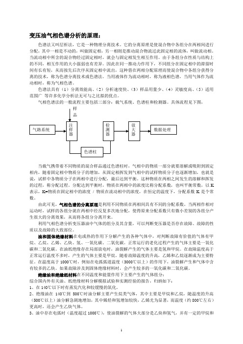
变压油气相色谱分析的原理:
仅仅根据分析结果的绝对值是很难对故障的严重性作出正确判断的,必须考察故障的发展趋势,也就是故障点(如果存在的话)的产气速率。产气速率是与故障消耗能量大小、故障部位、故障点的温度等情况直接有关的。若总炔的相对产气速率大于10%时应引起注意。
2)、过热性故障占少油设备(互感器和电容套管)故障比例较少,发生的部位主要为:电流互感器的一次引线紧固螺母松动,分流比抽头紧固螺母松动等;电容套管的穿缆线鼻与引线接头焊接不良,导管与将军帽等连接螺母配合不当等。
2、放电故障发生的部位:
1)、高能量放电(电弧放电)在变压器、套管、互感器内均有发生。引起电弧放电故障原因通常是线圈匝层间绝缘击穿,过电压引起内部闪络,引线断裂引起的闪弧,分接开关飞弧和电容屏击穿等。这种故障气体产生剧烈、产气量大,故障气体往往来不及溶解于油而聚集到气体继电器引起瓦斯动作。
3、油中存在电弧时(温度超过1000℃),使油裂解的气体大部分是乙炔和氢气,并有一定的甲烷和乙烯等。
4、备在运行中,由于负荷变化所引起的热胀和冷缩,用泵循环油所引起的湍流,以及铁芯的磁滞伸缩效应所引起的机械振动等,都会导致形成空穴和油释放溶解气体。如果产生的气泡集在设备绝缘结构的高电压应力区域内,在较高电场下会引起气隙放电(一般称为局部放电)而放电本身又能进一步引起油的分解和附近的固体绝缘材料的分解,而产生气体,这些气体在电应力作用下会更有利于放电产生气体。这种放电使油分解产生的气体主要是氢和少量甲烷气体。
3)、局部放电是指油和固体绝缘中的气泡和尖端,因耐压强度低,电场集中发生的局部放电。这种放电不断慢延与发展,会引起绝缘的损伤(碳化痕迹或穿孔)。如电流互感器和电容套管的电容芯绕包工艺不良或真空干燥工艺不良等,都会造成局部放电。
- 1、下载文档前请自行甄别文档内容的完整性,平台不提供额外的编辑、内容补充、找答案等附加服务。
- 2、"仅部分预览"的文档,不可在线预览部分如存在完整性等问题,可反馈申请退款(可完整预览的文档不适用该条件!)。
- 3、如文档侵犯您的权益,请联系客服反馈,我们会尽快为您处理(人工客服工作时间:9:00-18:30)。
一、气路系统 二、进样系统 三、色谱柱 四、温度控制系统 五、检测系统
22:49:08
概述
气相色谱法:以气体为流动相的柱色谱分离技术
1. 按固定相分
气-固色谱 气-液色谱 2. 按分离原理分 吸附色谱 分配色谱 3. 按柱子粗细分 填充柱色谱 毛细管柱色谱
22:49:08
气相色谱法的特点和应用
“三高” “一快” “一广” 1. 高效能:一般填充柱的理论塔板数可达数千,毛细管 柱可 达一百多万。 2. 高选择性:可以使一些分配系数很接近的以及极为复 杂、难以分离的物质,获得满意的分离。 3. 高灵敏度:可以检测1011~1013g物质,适合于痕量 分析。 4. 分析速度快:通常一个试样的分析可在几分钟到几十 分钟内完成。 5. 应用广泛:可以分析气体试样,也可分析易挥发或可 衍生转化为易挥发的液体和固体。分析的有机物,约占全部 有机物(约300万种)的20%。
22:49:08
五、检测系统
色谱仪的眼睛 通常由检测元件、放大器、显示记录三部分组成; 被色谱柱分离后的组分依次进入检测器,按其浓度或质 量随时间的变化,转化成相应电信号,经放大后记录和显示, 给出色谱图; 检测器:广普型——对所有物质均有响应; 专属型——对特定物质有高灵敏响应; 常用的检测器:热导检测器、氢火焰离子化检测器
C min
22:49:08
mmin Q
4. 线性范围宽
检测器的线性范围定义:检测器的响应信号与被测组分质量 或浓度呈线性关系的范围。通常以检测器在线性工作时,被 测物质的最大浓度(或质量)与最低浓度(或质量)之比表
示。
22:49:08
三、热导检测器
thermal conductivity detector,TCD 1. 结构
22:49:08
一、检测器类型
第二节 检测器
detector of gas chromatograph
specific property of detector
二、优良检测器的性能指标 三、热导检测器TCD
thermal conductivity detector
四、氢火焰离子化检测器
flame ionization detector, FID
22:49:08
色谱柱主要有两类:填充柱和毛细管柱。 1. 填充柱 填充柱由不锈钢或玻璃材料制成,内装固定 相,一般内径为2~4 mm,长1~3m。填充柱的形状有U型和 螺旋型二种。
2. 毛细管柱 毛细管柱又叫开管柱,分为涂壁,多孔层和 涂载体空心柱。涂壁空心柱是将固定液均匀地涂在内径0.l~ 0.5mm的毛细管内壁而成,毛细管材料可以是不锈钢,玻璃 或石英。毛细管色谱柱渗透性好,传质阻力小,而柱子可以 做到长几十米。与填充柱相比,其分离效率高(理论塔板数 可达106)、分析速度快、样品用量小,但柱容量低、要求检 测器的灵敏度高,并且制备较难。
22:49:08
三、色谱柱(分离柱)
色谱柱:色谱仪的核心部件。 柱材质:不锈钢管或玻璃管,内径3-6毫米。长度可根据 需要确定。 柱填料:粒度为60-80或80-100目的色谱固定相。
气-固色谱:固体吸附剂
气-液色谱:担体+固定液
柱制备对柱效有较大影响,填料装填太紧,柱前压力大, 流速慢或将 柱堵死,反之空隙体积大,柱效低。
22:49:08
填充柱
色谱柱 填充柱
毛细管柱
毛细管柱
柱内径
柱长度 总塔板数 样品容量
22:49:08
1-10 mm
0.5-10 m ~103 10-1000
0.05-0.5 mm
10-150 m ~ 106 0.1-50
四、温度控制系统
温度是色谱分离条件的重要选择参数; 气化室、分离室、检测器三部分在色谱仪操作时均需控制 温度; 气化室:保证液体试样瞬间气化; 检测器:保证被分离后的组分通过时不在此冷凝; 分离室:准确控制分 离需要的温度。当试样 复杂时,分离室温度需 要按一定程序控制温度 变化,各组分在最佳温 度下分离;
22:49:08
气相色谱仪器
gas chromatographic instruments
22:49:08
气相色谱仪器
22:49:08
气相色谱仪器
22:49:08
气相色谱仪示意图
22:49:08
气相色谱仪组成部件:
气路系统 进样系统 色谱柱 检测系统
温控系统
22:49:08
一、气路系统
包括气源、净化干燥管和载气流速控制; 常用的载气有:氢气、氮气、氦气; 净化干燥管:去除载气中的水、有机物等杂质(依次通过 分子筛、活性炭等); 载气流速控制:压力表、流量计、针形稳压阀,控制载气 流速恒定。
氢焰检测器的原理
(4) 化学电离产生的正离子和电子在外加恒 定直流电场的作用下分别向两极定向运动而 产生微电流(约10-6~10-14A); (5) 在一定范围内,微电流的大小与进入离
子室的被测组分质量成正比,所以氢焰检测
器是质量型检测器。 (6) 组分在氢焰中的电离效率很低,大约五
图 氢火焰各层图 A区:预热区 B层:点燃火焰
十万分之一的碳原子被电离。
(7)离子电流信号输出到记录仪,得到峰面 积与组分质量成正比的色谱流出曲线
22:49:08
C层:热裂解区:
温度最高 D层:反应区
4. 影响氢焰检测器灵敏度的因素
①各种气体流速和配比的选择
N2流速的选择主要考虑分离效能,
N2∶H2 = 1∶1~1∶1.5 氢气∶空气=1∶10。 ②极化电压 正常极化电压选择在100~300V范围内。
钨丝通电,加热与散热达到平衡后,两臂电阻值:
R参=R测 ; R1=R2 则: R参· R2=R测· R1
无电压信号输出; 记录仪走直线(基线)。
22:49:08
进样后:
载气携带试样组分流过测量臂而这时参考臂流过的仍是 纯载气,使测量臂的温度改变,引起电阻的变化,测量臂和 参考臂的电阻值不等,产生电阻差,R参≠R测 则: R参· R2≠R测· R1 这时电桥失去平衡,a、b 两端存在着电位差,有电压信
22:49:08
二、 进样系统
进样装置:进样器+气化室; 气体进样器(六通阀):推拉式和旋转式两种。 试样 首先充满定量管,切入后,载气携带定量管中的试样气体 进入分离柱;
取样位置
22:49:08
试样导入色谱柱
六通阀进样器
液体进样器:
不同规格的专用注射器,填充柱色谱常用10μL; 毛细管色谱常用1μL;新型仪器带有全自动液体进样 器,清洗、润冲、取样、进样、换样等过程自动完 成,一次可放置数十个试样。 气化室:将液体试样瞬间 气化的装置。无催化作用。
表7-1 某些气体与载气的热导系数(λ),单位:J / cm· ℃· s
22:49:08
四、氢火焰离子化检测器
1. 特点
flame ionization detector, FID
简称氢焰检测器
(1) 典型的质量型检测器; (2) 对有机化合物具有很高的灵敏度; (3) 无机气体、水、四氯化碳等含氢少或不含氢的物质 灵敏度低或不响应; (4) 氢焰检测器具有结构简单、稳定性好、灵敏度高、 响应迅速等特点; (5) 比热导检测器的灵敏度高出近3个数量级,检测下限 可达10-12g· g-1。
22:49:08
二、优良检测器的性能指标
1. 灵敏度(或响应值)S 高: 在一定范围内,信号 E 与进入检测器的物质质量m 呈线 性关系: E=Sm S= E/m 单位: mV/(mg / cm3) ;(浓度型检测器) mV /(mg / s) ;(质量型检测器) S 表示单位质量的物质通过检测器时,产生的响应信 号的大小。S值越大,检测器(也即色谱仪)的灵敏度也就 越高。检测信号通常显示为色谱峰,则响应值也可以由色 谱峰面积(A)除以试样质量求得: S=A/m
第七章 气相色谱法
gas chromatographic analysis ,GC
Hale Waihona Puke 第一节 气相色谱仪 第二节 检测器 第三节 填充柱气相色 谱固定相 第四节 开管柱气相色 谱法 第五节 定性和定量方 法 第六节 气相色谱法的 应用
22:49:08
第一节 气相色谱仪
gas chromatographic instruments
②池体温度:池体温度与钨丝温度相差越大,越有利
于热传导,检测器的灵敏度也就越高,但池体温度不能低于 分离柱温度,以防止试样组分在检测器中冷凝。
22:49:08
③载气种类:载气与试样的热导系数相差越大,在检测
器两臂中产生的温差和电阻差也就越大,检测灵敏度越高。 载气的热导系数大,传热好,通过的桥路电流也可适当加大 ,则检测灵敏度进一步提高。氦气也具有较大的热导系数, 但价格较高。
噪声水平决定着能被检测到的浓度(或质量)。
检测器响应值为2倍噪声水平时的试样浓度(或质量),被定
义为最低检测限(或该物质的最小检测量)。 最小检测量与检测限是两个不同的概念。检测限只用来衡量 检测器的性能,而最小检测量不仅与检测器性能有关,还与 色谱柱效及操作条件有关。 m 1.065W D
min 1 / 2(t )
号输出。信号与组分浓度相关。
记录仪记录下组分浓度随时间 变化的峰状图形。
22:49:08
3. 影响热导检测器灵敏度的因素
①桥路电流I : I,钨丝的温度 ,钨丝与池体之间的
温差 ,有利于热传导,检测器灵敏度提高。检测器的灵敏
度S ∝ I3,但稳定性下降,基线不稳。桥路电流太高时,还 可能造成钨丝烧坏。
图 氢焰检测器示意图
22:49:08
五、电子捕获检测器
electron capture detector, ECD
• 高选择性检测器; • 仅对含有卤素、磷、硫、氧等电负性高的元素的化合物 有很高的灵敏度,检测下限10-14 g /mL; • 对大多数烃类没有响应。 • 较多应用于农副 产品、食品及环境中 农药残留量的测定。
