aurcord操作手册
阿朗传输网管使用手册V2
阿朗传输网管使用手册目录1 网管登陆 (1)2 当前告警查看 (2)3 拓扑查看: (3)4 光功率查询 (7)5 历史告警查询 (9)前言:鹰潭、吉安、景德镇PTN网络使用阿尔卡特传输设备,设备型号主要有1850TSS-320,1850TSS-160,1850TSS-5C和1850TSS-5R,后缀代表设备容量,比如:1850TSS-320代表设备最大支持320G的多速率交叉能力(相当于2048个155M)。
1850TSS-320和1850TSS-160主要用于汇聚层设备,1850TSS—5R主要用于接入层设备,带基站业务或宽带业务。
由于1850TSS-5C问题较多且容量不足,已逐渐升级成5R设备。
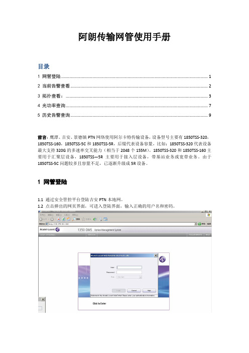
1 网管登陆1.1 通过安全管控平台登陆吉安PTN本地网。
1.2 点击弹出的网页界面,可进入登陆界面,输入正确的用户名和密码。
2.1 登陆成功后,选择左边菜单-》Operation-》Alarms,双击Gobal Alarms图标。
2.2 此时弹出告警浏览界面,监控主要关注MAJOR级别告警:Loss of Signal以及Hardware failure,点击左边树图中MAJOR栏,可选择查看MAJOR级别告警。
勾选掉菜单View-》Paginate sublist选项,可取消告警分页显示,提高告警查看效率。
若告警变成绿色表示告警已清除,若找不到此告警,表明告警已清除且被存入历时库,历史库中的告警需要登陆网元主页中查询,详见第5节。
由于告警查看界面无法关联到拓扑,要查看网络拓扑,需要启动Network Management服务,详见第3节。
3.1在登陆主界面中,选择左边菜单-》Operation-》Management,双击Network Management 图标。
3.2 根据告警信息,查找告警网元:选择菜单Search-》Physical-》Nodes,可以显示所有网元,按Location(区县)排序,可以找到对应网元,注意区分5R和5C设备。
Sony NX5u Camcorder使用手册说明书
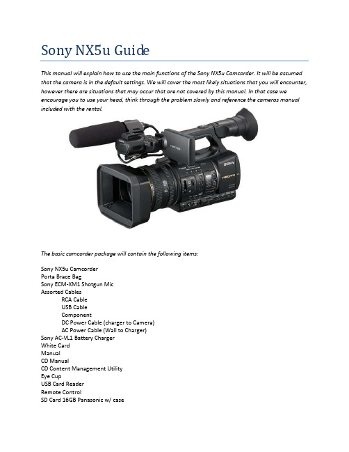
Sony NX5u GuideThis manual will explain how to use the main functions of the Sony NX5u Camcorder. It will be assumed that the camera is in the default settings. We will cover the most likely situations that you will encounter, however there are situations that may occur that are not covered by this manual. In that case we encourage you to use your head, think through the problem slowly and reference the cameras manual included with the rental.The basic camcorder package will contain the following items:Sony NX5u CamcorderPorta Brace BagSony ECM-XM1 Shotgun MicAssorted CablesRCA CableUSB CableComponentDC Power Cable (charger to Camera)AC Power Cable (Wall to Charger)Sony AC-VL1 Battery ChargerWhite CardManualCD ManualCD Content Management UtilityEye CupUSB Card ReaderRemote ControlSD Card 16GB Panasonic w/ caseReference Image #2Reference Image #4Turning the camera onThe camera can take power from either a wall outlet or a battery. The battery should be obvious so I will only describe the wall outlet option. Pgs. 12-16 in the manual1.Remove the battery charger, DC Power Cable (charger to Camera), and AC Power Cable (Wall toCharger) from the bag.2.Connect the power cord to the wall outlet3.Connect the DC coupler cord to the AC Adapter/Charger4.Set the mode switch of the AC Adapter/Charger to VCR/CAMERA.5.Attach the DC coupler to the Cameras battery slot.6.Turn on the Camera. Rotate the On/Off switch from off to on.Setting up the Memory CardsThe camera will record onto SD media cards with a Class 6 or higher rating. The station supplies a single 16GB Class 10 SD card for your use. Be sure to format or erase all data on the cards you intend to use prior to shooting as the camera cannot erase the cards during recording. Pgs. 19, 24-26 in the Manual.1.Insert your media card into the camera card slots located next to the battery.a.The protective cover opens from right to left.b.The angled corner on the SD card faces down.2.With the camera turned on, press MODE.3.Press MODE again and choose MANAGE MEDIA.4.Select MEDIA FORMAT and then the card you wish to format.5.Confirm twice and the selected media will be formatted.Changing the Record FormatIn this step you will be changing the record settings. This includes switching between SD/HD and changing the recording quality.1.Press the MODE button, Select CAMERA, and then MOVIE.2.Press MENU and navigate to REC/OUT SET and then REC SET.a.Choose the HD/SD mode that works for youb.The left column determines what will be recorded on the SD cards and the right columndetermines what will be recorded on the external hard drive (not included).3.Selection of an option returns you to the previous screen.4.Next open REC FORMAT.a.The left column is HD and the right column is SD.b.Only one column will be available. Which one depends on your choice in step 2.c.FX,FH,HQ,LP are quality settings. FX has the best recording quality and LP has thelongest runtime.d.I recommend shooting in 1080/30p FX or 720/60p FX.5.After making your selection, accept the change and press MENU to exit.6.You are ready to record.Adjusting for the shotThese are the settings that you need to change to adjust exposure and color balance for each shot.1.With the camera Turned on and the lens cap open, point the camera at your subject.2.Default the settings as follows.a.Set the AUTO-MAUNUAL button to MANUALb.Set the IRIS to F4c.Set the GAIN to L or 0DBd.Set the ND FILTER to OFFe.Set the SHUTTER to twice your frame rate.f.Set FOCUS to MAN3.Adjust the image so that it is properly exposed.a.Try to keep the F-Stop between F3.7-F5.6e the ND FILTER to reduce the light.e the GAIN to boost the lighti.Avoid using GAIN if at all possibleing the shutter to boost or reduce light also worksi.Be aware that the SHUTTER controls motion blur.4.White Balance the Cameraa.Place the white card nearest to the object you want to be the most correct in the shot.b.Zoom in as close as you can to the card and adjust the white balance appropriately.c.Refer to the camera manual for details on how to white balance.5.Your video should now be ready to record.Don’t forget the AudioAudio is an all too often overlooked aspect of video production. I will describe the process of routing and balancing your audio levels in the camera.1.Plug your microphone into INPUT 1 and/or INPUT2.ing the Input type panel located behind the XLR inputs, designate the appropriate mic typefor each input.a.Line for audio from devices, mic for dynamic microphones and mic+48V formicrophones that require phantom power3.Now look at the audio panel on the left side of the camera.a.This panel affects the recorded audio channels4.The left two switches are channel inputs.a.You are recording two audio channels at any point in time, these switches determinefrom where each channel receives its audio.b.Channel 1 can receive audio from either XLR Input 1 or the internal mic.c.Channel 2 can receive its audio from XLR Input 1, XLR Input 2, or the internal mic.5.The two switches in the middle change the gain controls from AUTO to MANUAL.a.Auto Gain Control or AGC is fairly accurate but cannot differentiate betweenbackground and foreground noise and will adjust itself.b.Manual mode will get the best results if you monitor and adjust the gain as needed.You are now ready to record your interviewOne of the great things about these cameras is the ease of reviewing the footage you just shot. Take your time with the setup and check your results and be sure to have fun.。
aurcord编程手册
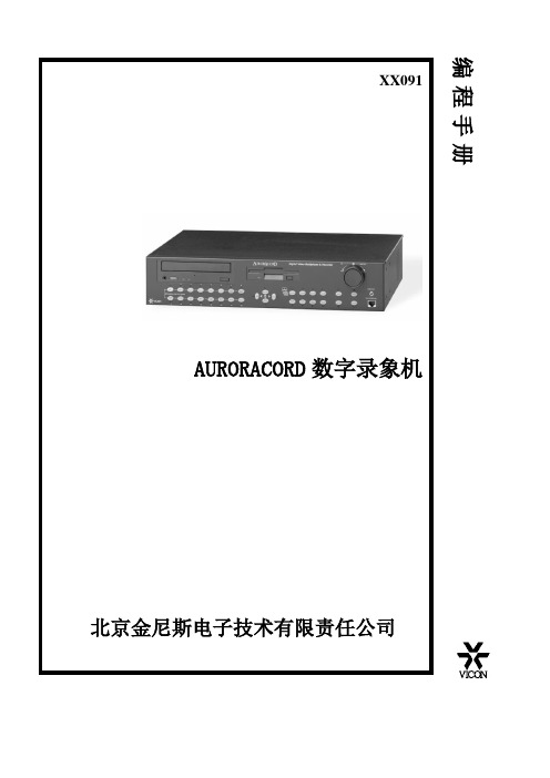
AURORACORD数字录象机编程该手册按下列次序编制1.预备步骤●进入菜单选项及主菜单●用帮助系统●菜单操作键●使用密码功能●设置时间、日期显示●定义颜色及边框深浅●完善显示参数●使用出厂恢复值2.摄象机,解码器及动态检测3.报警4.录象功能5.回放功能6.计划7.串口设置预备步骤一.进入菜单选项屏幕及主菜单1.运行下列步骤进入菜单选项屏幕及主菜单●请连接监视器到AURCORD录象机主显示器BNC输出,并接通电源;●在系统启动信息提示过之后,AURCORD录象机的LOGO标显示后,键屏幕显示下列编程屏幕Easy Setup MENU 快速设置2. Main Menu 主菜单3. Camera Calibration 摄象机校准Save/Restore Menu 存盘还原5. Language 语言Screen 常见问题屏幕About Aurcord 关于AURCORD●按数字键2主菜单DISPLAY SETUP 显示建立CAMERA SETUP 摄象机建立ALARM SETUP 报警建立SERIAL PORT SETUP 串口建立SETUP 时间/日期建立RECORD/PLAYBACK SETUP 录象/回放建立SYSTEM SETUP 系统建立磁盘功能二.使用在线帮助系统AURCORD关需要的信息;按键进入或退出帮助系统,帮助系统提供系统任何功能的信息;常见问题的回答可以从下面的屏幕获得,也可以从主菜单选项中进入三、屏幕菜单操作按键AURCORD菜单操作包含进入子菜单,光标上下移动,及选择参数等操作,实际上,箭头键及数字键是经常使用系统编程一、设置时间日期显示首先定义时间、日期的显示模式(如显示、关闭及定义消隐时间),两个菜单需要进入,一个是定义主屏幕,另外是定义从监视器。
定义时间、日期参数执行下列步骤:按MENU键进入下面菜单按数字键2进入下级菜单主菜单DISPLAY SETUP 显示建立CAMERA SETUP 摄象机建立ALARM SETUP 报警建立SERIAL PORT SETUP 串口建立SETUP 时间/日期建立RECORD/PLAYBACK SETUP 录象/回放建立SYSTEM SETUP 系统建立磁盘功能按数字键5进入下级菜单TIME/DATE SET 时间日期设置SET TIME 设定时间SET DATE 设定日期DAY LIGHT SAVINGS 夏时制NO 24小时模式DEF. 时间出厂模式按数字键1进入设置时间菜单SET TIME 设置时间按数字键输入时间,按按数字键2进入设置日期菜单SET DATE 设置时间按数字键输入日期,按二、定义摄象机字符按MENU键进入下面菜单按数字键2进入下级菜单主菜单DISPLAY SETUP 显示建立CAMERA SETUP 摄象机建立ALARM SETUP 报警建立SERIAL PORT SETUP 串口建立SETUP 时间/日期建立RECORD/PLAYBACK SETUP 录象/回放建立SYSTEM SETUP 系统建立磁盘功能按数字键2进入下级菜单摄象机设置CAMERA CALIBRATION 摄象机校准CAMERA TITLES 摄象机字符UPDATE PRIORITLES 设定优先级RECEIVER TYPE 解码器型号MOTION SETUP 动态设置FINE TUNE 微调按数字键2进入设置字符菜单摄象机字符CHANGE CAMERA TILTLES 改变象机字符USE CAM NUMBER AS TILTLEUSE TITLE DEFAULTS 用字符出厂值按数字键1进入设置字符菜单改变摄象机字符按数字键选择对应修改的摄象机字符按左、右箭头移动光标,按上、下箭头改变字符;按SEQ/MPTZ选择行,按ZOOM+/-插入或删除字符,按ENTER存储三、动态检测按MENU键进入下面菜单按数字键2进入下级菜单主菜单DISPLAY SETUP 显示建立CAMERA SETUP 摄象机建立ALARM SETUP 报警建立SERIAL PORT SETUP 串口建立SETUP 时间/日期建立RECORD/PLAYBACK SETUP 录象/回放建立SYSTEM SETUP 系统建立磁盘功能按数字键2进入下级菜单摄象机设置CAMERA CALIBRATION 摄象机校准CAMERA TITLES 摄象机字符UPDATE PRIORITLES 设定优先级RECEIVER TYPE 解码器型号MOTION SETUP 动态设置FINE TUNE 微调按数字键5进入动态检测菜单摄象机动态建立设定阈值设定最小激活区设定动态处理禁止动态处理用动态出厂值按1摄象机动态建立,对每个摄象机进行设定摄象机号摄象机字符动态处理设定阈值最小激活区按2 设定动态的阈值,1-9可选,调整动态的灵敏度按3设定动态检测的最小块数按4设定动态检测处理的方式:如果要报警,必须设为ALARM三、报警AURCORD录象机报警设置步骤如下:1.设置报警输入2.报警输出3.报警格式和报警信息4.报警确认5.报警图象联动一、报警输入按MENU键进入下面菜单按数字键2进入下级菜单主菜单DISPLAY SETUP 显示建立CAMERA SETUP 摄象机建立ALARM SETUP 报警建立SERIAL PORT SETUP 串口建立SETUP 时间/日期建立RECORD/PLAYBACK SETUP 录象/回放建立SYSTEM SETUP 系统建立磁盘功能按数字3进入报警菜单报警建立ALARM INPUTS 报警输入ALARM OUTPUT 摄象机建立ACKNOWLEDGE 报警自动确认ALARM ON/OFF ACTIONS 报警动作DEFAULTS 用报警出厂值按数字3进入报警输入菜单报警建立Alarm contacts 报警干接点Motion Setup 动态建立Rcvr alarm 解码器报警Video Loss 视频丢失按数字1进入报警干接点设置能/禁止输入报警解码器报警按数字键1,对每个干接点的能/不能进行设置按数字键2,对干接点的类型:瞬时/锁定进行设置按数字键5,对干接点的类型:常开进行设置按数字键5,对干接点的类型:常闭进行设置二、报警输出按MENU键进入下面菜单按数字键2进入下级菜单主菜单DISPLAY SETUP 显示建立CAMERA SETUP 摄象机建立ALARM SETUP 报警建立SERIAL PORT SETUP 串口建立SETUP 时间/日期建立RECORD/PLAYBACK SETUP 录象/回放建立SYSTEM SETUP 系统建立磁盘功能按数字3进入报警菜单报警建立ALARM INPUTS 报警输入ALARM OUTPUT 报警输出ACKNOWLEDGE 报警自动确认ALARM ON/OFF ACTIONS 报警动作DEFAULTS 用报警出厂值按数字2进入报警输出菜单报警建立ALARM CONTACTS 报警干接点DISABLE 报警蜂鸣ON ANY ALARM 报警继电器按数字键2,设置报警蜂鸣器是否响按数字3,设置报警继电器动作二、报警显示格式、切换及报警信息按MENU键进入下面菜单按数字键2进入下级菜单主菜单DISPLAY SETUP 显示建立CAMERA SETUP 摄象机建立ALARM SETUP 报警建立SERIAL PORT SETUP 串口建立SETUP 时间/日期建立RECORD/PLAYBACK SETUP 录象/回放建立SYSTEM SETUP 系统建立磁盘功能按数字3进入报警菜单报警建立ALARM INPUTS 报警输入ALARM OUTPUT 报警输出ALARM DISPLAY 报警显示ACKNOWLEDGE 报警自动确认ALARM ON/OFF ACTIONS 报警动作DEFAULTS 用报警出厂值按数字3进入报警显示菜单报警显示MAIN+SPOT 报警信息BRRED 报警文本颜色NO CHANGE 显示格式NO CHANGE 主屏幕切换NO CHANGE 从屏幕切换按1设置报警信息,可以改变下列模式:MAIN+SPOT(信息显示在两个监视器上)MAIN(信息显示在主屏幕)SPOT(信息显示在从屏幕)OFF(关闭)按2设置报警信息文本颜色按3设置报警显示格式:全屏、四画面、六画面等按4设置主画面报警画面切换:按5设置从画面报警画面切换:上述设置上、下箭头用于移动,向左箭头用于返回,向右箭头及数字键用于选择三、录象/放像一、录象按MENU键进入下面菜单按数字键2进入下级菜单主菜单DISPLAY SETUP 显示建立CAMERA SETUP 摄象机建立ALARM SETUP 报警建立SERIAL PORT SETUP 串口建立SETUP 时间/日期建立RECORD/PLAYBACK SETUP 录象/回放建立SYSTEM SETUP 系统建立磁盘功能按数字键6进入录象/RECORD SETUP 录象建立PLAYBACK SETUP 放像建立按数字键1进入录象菜单主菜单CAMERAS 录象建立按数字键1,对每个摄象机录象质量进行设置,一般为HIGHEST(最高)按数字键2,对每个摄象机是否录象进行设置按数字键3,对报警摄象机录象次序进行调整按数字键3/4,录象或停止录象按数字键6,录象图象刷新率,一般设为7一、放像1.选择回放源按MENU键进入下面菜单按数字键2进入下级菜单主菜单DISPLAY SETUP 显示建立CAMERA SETUP 摄象机建立ALARM SETUP 报警建立SERIAL PORT SETUP 串口建立SETUP 时间/日期建立RECORD/PLAYBACK SETUP 录象/回放建立SYSTEM SETUP 系统建立磁盘功能按数字键6进入录象/RECORD SETUP 录象建立PLAYBACK SETUP 放像建立按数字键2进入回放界面START PLAYBACK 开始回放结束回放选择播放源PLAYBACK SEARCH 回放搜索OFF 回放音频5 音频音量按数字键1/2选择开始/停止播放按数字键3选择回放源,有软盘、光盘,硬盘三种模式按数字键4回放搜索按数字键1,进入按时间搜索按数字键1,修改时间,用上下箭头修改时间,用左右箭头移动位置按数字键2,修改日期,用上下箭头修改日期,用左右箭头移动位置按数字键3,开始按选定时间点搜索按数字键2,进入按报警搜索会出现报警列表,选择一个报警,就可以回放报警录象按数字键3,进入按动态搜索会出现报警列表,选择一个报警,就可以回放动态录象四、串口按MENU键进入下面菜单按数字键2进入下级菜单主菜单DISPLAY SETUP 显示建立CAMERA SETUP 摄象机建立ALARM SETUP 报警建立SERIAL PORT SETUP 串口建立SETUP 时间/日期建立RECORD/PLAYBACK SETUP 录象/回放建立SYSTEM SETUP 系统建立磁盘功能按数字键4进入串口设置菜单PRN/HOST 串口1115200 串口2按数字键1,进入串口1设置按数字键2,进入串口2设置按数字键3进入AURNET设置如果AURCORD录象机要组成AURNET网络,对每个设备地址是不同,按数字2进行设置。
AUREL RTX5MID868 FSK OOK RF数码通信模块用户手册说明书
Blocking test at ± 10MHz
To Be Defin.
dB
See note 3
Image frequency rejection
To Be Defin.
dB
See note 2
Output square wave
0,05
1
3
KHz
Input square wave
0,01
3
kHz
RSSI (pin 8)
AUR.EL RTX-MID-868-FSK
AUR.EL RTX-MID-868-OOK
---------------------------------------------------------------------------------------------------------------------------------------------------来自-109-111
dBm
RF irradiated power (OOK and FSK)
7
8,5
10
dBm
FSK ∆F deviation
±25
KHz
See note 1
OOK Modulation
100
%
Blocking test at ± 2MHz
To Be Defin.
dB
See note 3
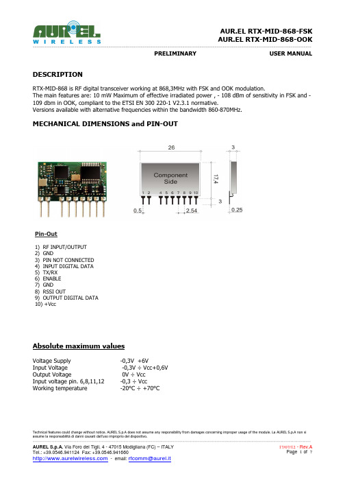
MECHANICAL DIMENSIONS and PIN-OUT
Pin-Out
1) RF INPUT/OUTPUT 2) GND 3) PIN NOT CONNECTED 4) INPUT DIGITAL DATA 5) TX/RX 6) ENABLE 7) GND 8) RSSI OUT 9) OUTPUT DIGITAL DATA 10) +Vcc
audition简单使用说明

Adobe Audition 3.0的简单使用方法软件简介:Adobe Audition是一个专业音频编辑和混合环境,原名为Cool Edit Pro. 被Adobe 公司收购后,改名为为Adobe Audition。
Audition专为在照相室、广播设备和后期制作设备方面工作的音频和视频专业人员设计,可提供先进的音频混合、编辑、控制和效果处理功能。
Audition 是一个完善的多声道录音室,可提供灵活的工作流程并且使用简便。
无论是要录制音乐、无线电广播,还是为录像配音,Audition中的恰到好处的工具均可为您提供充足动力,以创造可能的最高质量的丰富、细微音响。
它是Cool Edit Pro 2.1 的更新版和增强版。
此汉化程序已达到98%的信息汉化程度。
一、录音:1.打开audition 3.0,文件/新建/新建波形/确定2.保存文件:文件/另存为3.打开录音控制台:选项/windows录音控制台,在“录音控制”面板中单击“选项/属性”,勾选“麦克风音量”,在“属性/混音器”中选择Audio Input,勾选“麦克风音量”,确定。
4.开始录音:在界面左下角的“传送器”面板中单击红色按钮,对着麦克风讲话,开始录音。
有波形说明录音正常,若无波形请检查第三步的录音设置。
5.停止录音:若录音完毕,单击红色按钮或者单击“传送器”最左端的停止按钮6.保存文件:文件/保存二、编辑:(一)编辑单个音频文件:1.调节音量、去除不需要的波形:在“编辑”视图下可以选择声音波形中的某段波形,单击鼠标右键可以“保存选区”,可以“剪切”并粘贴到其他波形文件中,还可以直接选择“静音(进程)”去除噪音。
在“停止”状态下选择波形文件可以直接调节音量大小,单击鼠标不放,往右或往上拖动则是调大声,往下或者往左拖动则是调小声。
2.设置音频的效果:打开“效果”面板,可以进行降噪、变调、回声、混响等效果设置。
例:选中噪声波形,点击”效果/修复/”,然后单击鼠标右键,波形”,单击“修复/3.保存文件:文件/保存。
调音台audition录音实验指导手册
调音台使用指导手册1.所需设备:ReVon RV-4调音台×1、Revon PRO-838麦克风×1、监听麦、3.5转6.5转接头×2、3.5转双莲花音频线×1。
注意:实验开始前,或接入设备前,四路推子皆置于-∞端(最底端)!以免损坏设备。
需录伴奏者自带MP3或MP4等音频播放设备。
2.设备连接及大致用法:将Revon PRO-838麦克风的6.5毫米接口插入ReV on RV-4调音台线路1的LINE口。
将双莲花头插入线路3/4的REC OUT接口,3.5毫米接口插入电脑MIC录音接口。
将监听麦用3.5转6.5转接头连接并插入PHONES接口。
如需利用自己MP3中的伴奏合成录音者,使用3.5毫米直通线一头接3.5转6.5转接头插入线路2的LINE口,另一头3.5毫米接MP3的耳机接口。
3.使用推子调节麦克风输入音量、外置设备输入音量、立体声输入音量、混合输出音量。
4.监听耳机的音量使用调音台右侧的PHONES旋钮调节。
5. 主要旋钮用途说明:PAN旋钮控制声像:它用来调整该通道信号在左右声道之间的立体声位置。
调节范围左声道5~右声道5,如不需要制作特殊效果,一般置于0处。
GAIN旋钮控制该路信号增益:它是用来调节输入信号电平大小的。
输入的信号以多大的电平来输出是由该旋钮和该输入单元的推子共同决定的。
显然,旋钮顺时针方向角度越大、推子越高,输入信号的输出电平的提升就越大,或者说该路输入的音频信号在输出中的响度就越大。
增益范围为20分贝到60分贝。
值得注意的是,增益太高会使声道负荷过载(重),导致声音失真;太低则背景噪音明显,可能也无法获得足够的讯号电平提供混音输出。
使用高电平输入时要将增益转小。
增益旋钮是作为声音输入调音台的关口,调整适当,即可保证调音台下一级的处理电路能接收到充分且“干净”的信号。
(HIGH、MID、LOW)旋钮为三段式均衡器:High、Middle、Low分别可以对高频、中频、低频进行增强或衰减,控制范围为正负15分贝。
System LactoCorder T-T 操作手册说明书
__________________________________________________________________________ System LactoCorder T-TOperating ManualDevelopment and productionWMB AGWegenstrasse 6 - CH-9436 BalgachTel. +41(0)71 727 18 30 - Fax +41(0)71 727 18 31E-mail ***********Internet www.wmb.ch________________________________________________________________________ TablePage 1 General.... . (1)1.1 Table........................................................................ . (1)2 INTRODUCTION (2)2.1 Note........................................................................... (2)2.2 Used abbreviations (2)2.3 Special regulations...................................................... (3)2.4 Care note.. .................................................................. .. 32.5 Appropriate use....................................... . 42.6 Transport (4)2.6.1 Packaging............................................................ . 42.6.2 Unpacking / Entrance control (4)2.6.3 Transport damage............................................. ...... . . 42.7 Safety (5)2.7.1 General............................................................ . 52.7.2 Special note.......................................... . 52.7.3 Selection of operating personnel (5)3 Test fluid for water tests (6)4 Setting up the LC T-T in the stable (6)5 One-time settings (6)6 Problem of a not completely empty LC T-T (7)7 Add the amount of the gap to the total quantity of milk?88 Calculation of the amount of milk whenmeasured without emptying.99 Battery management........................................................... .1010 Possible errors and their solutions................................... .1011 Transfer of data to LactoPro (11)2 Introduction2.1 NoteRead these operatinginstructions before unpackingand before commissioning thedevice and pay close attention!The device may only be usedby persons familiar with theoperating instructions and theapplicable regulations onoccupational safety andaccident prevention.2.2 Uses AbbreviationsLC T-T= LactoCorder T-TThe following names or signs are used in the operating instructions forparticularly important information:Attention Indications of risk of injury to persons or risk ofdamage to equipment parts2.3 Special provisionsmeasuring instrument that has to be treatedwith care.The following actions and applications areprohibited and release the manufacturer fromany warranty:1. Immersion or cleaning with high pressurecleaning equipment, compressed air anddirect water jet (IP 64)2. Use of solvents or solvent-based substanceand non-standard cleaning products notapproved for milking machines3. Separate mechanical or chemical cleaningof the probes (e.g. brushes with abrasivesor similar)4. Mechanical force effects due to impacts andimproper handling5. Falls and transport damage6. Processing of the equipment different fromthe maintenance and repair instructions7. Tighten screws without paying attention tothe pre-written torques (Ncm)2.4 Care noticeThe following care instructions are required to maintainthe functionality of the LC T-T.After measuring carry out internal cleaningwith the cleaning program.Then remove the blowpipe and clean it separately.2.5 Appropriate useThe LC T-T is only used to check the quality and quantity ofanimal milk.Any other use or in excess is considered improperas intended. The resulting damages the manufacturer is not liable.The user bears the risk alone.The intended application also includes the observance ofinstructions and compliance with the inspection andMaintenance conditions.2.6 Transport2.6.1 PackagingKeep the carton and packaging material for alater transport so that the device can be transported safely.2.6.2 Unpacking / Entrance ControlThe shipping container for machines and equipment keeps normalstresses during transport on roads, rails and inthe air.Before you put the device into operation, check whether theparts listed on the delivery note are completely and undamagedin the scope of delivery. If the scope of delivery isfaulty - please contact our customer service.2.6.3 Transport DamageFor damage caused during transport, the transport companyis responsible. A full report that assesses the damagedescribed in detail, the transport company must be submitted to themand serves as the basis for the claim for damages.Damage or loss of the goods delivered by us are to be reported to usimmediately and has to be confirmed by a copy of the above-mentioned report.________________________________________________________________________2.7 Safety2.7.1 GeneralThe design of the LC T-T corresponds to the current state oftechnology and is reliable.The individual modules as well as the complete device aretested by our quality assurance.Only use the device when it is in perfect condition and inaccordance with its intended purpose, consciously takinginto account the operating instructions.Faults that may affect operational safety,eliminate immediately.2.7.2 Special noteBefore commissioning the device, read the operating instructionscarefully.Lack of knowledge about the operation and support of the systemcan cause damage to the LC T-T.Keep the operating instructions always at the place of use!Changes or modifications to the device are not permittedwithout the approval of the supplier.No program changes (software) to programmablecontrol systems!2.7.3 Selection of operating personnelWork on the LC T-T may only be carried out by well-instructedpersonnel.Use only well-trained personnel. Regulate the responsibilityof the staff for equipping, operating, maintenance,and repairing clearly.3 TEST FLUID FOR WATER TESTSTo preserve the test liquid for the water tests, mix 45 ml Neoagrar with15.75 kg Water. This mixture should have a conductivity between 5.5 and 6.5mS.4 SETTING THE LC T-T IN STABLEThe LC T-T can be hung with hanging brackets or plug-in brackets orpositioned in the stable.The devices should hang as vertically as possible.The hose guide is important. The hoses should be as short as possible. TheMilk must always be able to drain completely. Standing milk would distortthe result of the measurement of the LC T-T.5 One-time settingThe following settings must be made once.5.1 Turn on LC T-T5.2 Put in the USB stick on the LC T-T5.3 In the main menu, press the button "9" twice in quick succession. Itappears the password entry for the hidden service menu.5.4 Enter the six digits password (complementary value 9) to the device numbere.g.: LC T-T Device number: 070086Password: 9299135.5 Confirm with the "ENTER" button.5.6 Press the "3" button (settings).Activate measurement online data5.7 Press button "1" (Online b. Measurement). The selection appearsif you want to measure with or without online data.In the first line appears the selected option.5.8 Press button "2" (with online data).Activate cleaning online data5.9 Press button "2" (Online b. Clean)5.10 Press button "2" (with online data) or button “1” (without online data) Setting language5.11 Press button "4" (select language)5.12 Press button "1" (German) » Select your language5.13 Press the "CLEAR" button, Back to the settings menu5.14 Switch to the next menu with the "ENTER" buttonLC T-T_empty after each measurement 5.15 Press button "5" (empty after measurement) Select if the LC T-T should be emptying or not after each measurement. (Our proposal is to choose for milk quantity measurement without emptying) Press the "1" button (without emptying), the LC T-T will not be emptied. Enter a weighted quantity of milk for online measurement 5.16 Press button "8" (weighted milk quantity) 5.17 Press button "2" 5.18 Switch to the next menu with "ENTER". Enter the sampling during online measurement 5.19 Press button "9" (Enter sample) 5.20 Press the "2" button Then, press four times "CLEAR" to get back to the main menu. 6 Problem of a not completely empty LC T-TVery low levels cannot be measured exactly, as the output of the pressure pipe is not completely covered with liquid. After emptying, an empty LC T-T is assumed. If the LC T-T is not empty at the start of the measurement, errors in the milk quantity measurement will result. Residual milk and milk foamPressure pipe for measuring the level of the milkFluid Cover LC T-T7 Add the amount of the gap to the total quantity of milk?It depends on the measurement procedure if the content of the sampling may be added on the LC T-T for the total or not.7.1 Milk quantity measurement and sampling at the same timeWhere sampling and milk quantity measurement are carried out jointly, theamount of milk split off from LC T-T may be added to the quantity of milk.7.2 Checking the quantity of milkThe test of the quantity of milk may be carried out without sampling.If the milk quantity measurement is carried out with sampling, usually the milk in the sampler will be emptied in the bucket of the current milking. In this case,the addition of the release quantity to the quantity of milk must be active.________________________________________________________________________LC T-TMilk poured into the bucket Milk bucket Milk through the aperture Level at the start of measuring Difference quantitiy Level at the end of measuring8 Calculation of the amount of milk when measured without emptyingIf the milk quantity measurement is checked without emptying, the remaining volume (difference volume) in the LC T-T has to be taken into account. The storage level in the LC T-T is always different at the end of a measurement. This milk quantity difference that must be taken into account. The LC T-T measures the storage level of the milk at the beginning (starting level) and at the end of the Measurement (final level). In this manner the weight of the milk, which remain in the LC T-T, will be added to the amount in the bucket. When counterweighing, it is necessary to add this milk, which is left inside in the LC T-T, is taken into account in order to guarantee the effective quantity of milk from the animal. The LC T-T quantity and the weigh can be compared as follows: Lc T-T Quantity = "milk in a bucket" + difference = quantity of milk of the animal________________________________________________________________________ 9 Battery managementThe LC T-T uses a lithium-ion battery with 4400 mAh. The battery indicator aboveon the right provides information about the capacity state of the battery.The following states are distinguished:Icon Battery condition MeasuresBattery 100% charged No measuresBattery 85% charged No measuresBattery 75% charged No measuresBattery 60% charged No measuresBattery 50% charged No measuresBattery 35% charged Replaced and charged battery on occasionBattery 25% charged Replace the battery after milking and LoadBattery 10% charged Immediately replace and charge the batteryno more milkingTable 1: Battery capacity indicator10 Possible errors and their solution10.1 Error: No filter inserted. Measurement not possible without filterThis error is displayed when starting up and starting the measurement when in theLC T-T no filter is inserted. Either the filter is missing or the magnet in the filter is not inserted.10.2 Display by measurement: Storage Online. Failed!For computing capacity reasons, the LC T-T does not have the option of making a PC error in USB communication. Therefore, it may be possible that a USB stick on the PC can still be read, but the LC T-T displays an error message. In this case, the USB stick should be replaced.If there is an error when writing the online data to the USB stick, it must be repeated or canceled. If this has been aborted, it can be transferred to the measurement data on the USB stick. Only then new online data can be recorded.10.3 Cleaning takes longer than there is space in the online dataA maximum of 90 min. online values can be recorded during a cleaning process.If a cleaning takes more than 90 min. it will indicate that a RAM overflow has occurred and that the online readings are not complete. In this case, the first 90 min. of the cleaning were recorded. This only applies to online values. Cleaning continues normally.11 Data transfer to LactoProThe measured data can be analyzed in LactoPro.This should be used with LactoPro version 6.0.90. This version can be obtained from WMB or from the website: www.wmb.ch/LCT-T/lactopro11.1 Data on the USB stickThe measurement data from the LC T-T is displayed on the USB stick in the folder "LCS measurement data". If this folder is not already available, the LC T-T will automatically create one. The measurement data file is made up of the abbreviation MD for measurement data, the operating number and the date when operating data was written to the LCS. If no operating data has been used, 0 is entered.e.g.: MD_1234567890123456_121115.DATMD: Identification for a measurement data file 1234567890123456: Operating number121115: On 12/11/2015 the operating data on the LC T-Twere loaded11.2 Transferring data to the PCThe desired measurement data file must be copied manually in the LactoPro folder in the following path:".. "LactoPro\Daten\Datapack"LCS_Messdaten"The LCS_Messdaten folder must be created manually once.The program "LactoPro" can then be started. The reading of the LC T-T measurement data is now the same as reading data from a data pack.Under "Data- Telepack -> Measurement and Operating Data DP -->PC"The LC T-T data can be viewed like the data from the LactoCorder in LactoPro.The following values are currently stored correctly:- Operating number- Animal number 2- Bottle ID- Device number- Time- Date- Milking place number- Battery status (0: full, 1: 2/3, 2: 1/3, 3 almost empty, 4 empty) - Total milking- Species11.3 Write data to USB stick:11.3.1 Turn on LC T-T11.3.2 Insert the USB stick on the LC T-T11.3.3 Switch to the next menu with the "Enter" button11.3.4 Button "5" (data transfer)11.3.5 Button "2" (data write)。
IDEALARC DC655操作手册.pdf_1702949820.612663说明书

Operator’s ManualSave for future reference Date PurchasedCode: (ex: 10859)Serial: (ex: U1060512345)For use with machines having Code Numbers:10501; 10502; 10503; 10504; 10506; 10507; 10508; 10509; 10510; 11324Register your machine:/registerAuthorized Service and Distributor Locator: /locatorRefer to /safety for additional safety information.Electromagnetic Compatibility (EMC)ConformanceProducts displaying the CE mark are in conformity with European Community Council Directive of 15 Dec 2004 on the approximation of the laws of the Member States relating to electromagnetic compatibility,2004/108/EC. It was manufactured in conformity with a national standard that implements a harmonized standard: EN 60974-10 Electromagnetic Compatibility (EMC) Product Standard for Arc Welding Equipment. It is for use with other Lincoln Electric equipment. It is designed for industrial and professional use. IntroductionAll electrical equipment generates small amounts of electromagnetic emission. Electrical emission may be transmitted through power lines or radiated through space, similar to a radio transmitter. When emissions are received by other equipment, electrical interference may result. Electrical emissions may affect many kinds of electrical equipment; other nearby welding equipment, radio and TV reception, numerical controlled machines, telephone systems, computers, etc.WARNING: This equipment is not intended for use in residential locations where the electrical power is pro-vided by the public low-voltage supply system. There may be potential difficulties in ensuring electromagnet-ic compatibility in those locations, due to conducted as well as radiated disturbances.Installation and UseThe user is responsible for installing and using the welding equipment according to the manufacturer’s instructions. If electromagnetic disturbances are detected then it shall be the responsibility of the user of the welding equipment to resolve the situation with the technical assistance of the manufacturer. In some cases this remedial action may be as simple as earthing (grounding) the welding circuit, see Note. In other cases it could involve construction of an electromagnetic screen enclosing the power source and the work complete with associated input filters. In all cases electromagnetic disturbances must be reduced to the point where they are no longer troublesome.Note: The welding circuit may or may not be earthed for safety reasons. Follow your local and national standards for installation and use. Changing the earthing arrangements should onlybe authorized by a person who is competent to assess whether the changes will increase therisk of injury, e.g., by allowing parallel welding current return paths which may damage theearth circuits of other equipment.Assessment of AreaBefore installing welding equipment the user shall make an assessment of potential electromagnetic prob-lems in the surrounding area. The following shall be taken into account:a) other supply cables, control cables, signaling and telephone cables; above, below and adjacent to thewelding equipment;b) radio and television transmitters and receivers;c) computer and other control equipment;d) safety critical equipment, e.g., guarding of industrial equipment;e) the health of the people around, e.g., the use of pacemakers and hearing aids;f) equipment used for calibration or measurement;g) the immunity of other equipment in the environment. The user shall ensure that other equipment beingused in the environment is compatible. This may require additional protection measures;h) the time of day that welding or other activities are to be carried out.Electromagnetic Compatibility (EMC)The size of the surrounding area to be considered will depend on the structure of the building and other activities that are taking place. The surrounding area may extend beyond the boundaries of the premises. Methods of Reducing EmissionsPublic Supply SystemWelding equipment should be connected to the public supply system according to the manufacturer’s rec-ommendations. If interference occurs, it may be necessary to take additional precautions such as filtering of the public supply system. Consideration should be given to shielding the supply cable of permanently installed welding equipment, in metallic conduit or equivalent. Shielding should be electrically continuous throughout its length. The shielding should be connected to the welding power source so that good electrical contact is maintained between the conduit and the welding power source enclosure.Maintenance of the Welding EquipmentThe welding equipment should be routinely maintained according to the manufacturer’s recommendations. All access and service doors and covers should be closed and properly fastened when the welding equip-ment is in operation. The welding equipment should not be modified in any way except for those changes and adjustments covered in the manufacturers instructions. In particular, the spark gaps of arc striking and stabilizing devices should be adjusted and maintained according to the manufacturer’s recommendations. Welding CablesThe welding cables should be kept as short as possible and should be positioned close together, running at or close to floor level.Equipotential BondingBonding of all metallic components in the welding installation and adjacent to it should be considered. However, metallic components bonded to the work piece will increase the risk that the operator could receive a shock by touching these metallic components and the electrode at the same time. The operator should be insulated from all such bonded metallic components.Earthing of the WorkpieceWhere the workpiece is not bonded to earth for electrical safety, nor connected to earth because of its size and position, e.g., ship’s hull or building steelwork, a connection bonding the workpiece to earth may reduce emissions in some, but not all instances. Care should be taken to prevent the earthing of the workpiece increasing the risk of injury to users, or damage to other electrical equipment. Where necessary, the connec-tion of the workpiece to earth should be made by a direct connection to the workpiece, but in some countries where direct connection is not permitted, the bonding should be achieved by suitable capacitance, selected according to national regulations.Screening and ShieldingSelective screening and shielding of other cables and equipment in the surrounding area may alleviate prob-lems of interference. Screening of the entire welding installation may be considered for special applica-tions1._________________________1 Portions of the preceding text are contained in EN 60974-10: “Electromagnetic Compatibility (EMC) prod-uct standard for arc welding equipment.”viiviiThank Youfor selecting a QUALITY product by Lincoln Electric. We want you to take pride in operating this Lincoln Electric Company product ••• as much pride as we have in bringing this product to you!viii viiiTECHNICAL SPECIFICATIONS – DC-655* European models meet IEC974-1 standards.1Also called “inverse time” or “thermal/magnetic” circuit breakers; circuit breakers which have a delay in tripping action that decreases as the magnitude of the current increases.3 Phase transformer with rectified DC outputINPUT POWER THREE PHASEDesignates welder complies with National Electrical ManufacturersAssociation requirements EW 1Class I with 100% duty cycle at 650Amps output. (Domestic,Canadian, and Export models)Designates welder complies with both Underwriters Laboratories (UL) standards and Canadian Standards Association (CSA)standards. (Canadian Model)GMAWFCAWGRAPHIC SYMBOLS THAT APPEAR ON RATING PLATE (LOCATED ON CASE BACK)Constant Voltage Output CharacteristicsNEMA EW 1 (100%)Designates welder complies with International Electrotechnical Commission requirements 974-1.(European Models)IEC 974-1Designates welder complies with low voltage directive and with EMC directive. (European models)CEDesignates welder can be usedin environments with increased hazard of electric shock.(European models)Designates welder complies with Underwriters Laboratories (UL)standards. (Domestic Models)SMAWSAWConstant Current Output CharacteristicsDesignates the degree of envi-ronmental protection provided by the power sources enclosure.IP-23Open Circuit Output Voltage U o Input Voltage Rating(s)U 1Input Current Rating(s)I 1Output Voltage Rating(s)U 2Output Duty Cycle Rating(s)X Output Current Rating(s)I 2DESIGN FEATURES AND ADVANTAGES• Separate output terminals for selecting high or low inductance as recommended for the welding process.• Power on/off switch with pilot light and thermostat tripped indicator light.• Full range output voltage (CV mode) and current (CC mode) control for easy operation.• Panel switches behind a latched front panel for remote or local output control, output on or remote selection, and CC, CV Sub-arc or CV MIG mode selection.• Panel knob settable CC arc force control with built-in adjustable “Hot Start”.• High efficiency output, and selectable “sleep mode”idle mode timer which shuts down input power if not used for extra energy conservation.• Fan as needed (F.A.N.). Solid state thermally con-trolled fan operates cooling fan only when required. Minimizes power consumption, operating noise and dust intake.• Hinged cover to protect output terminals and auxil-iary connections.• Electronic and thermostatic protection for current overload and excessive temperatures.• 42 VAC, 10 amp auxiliary power available for the wire feeder; circuit breaker protected.• 115 VAC, auxiliary power protected by a 20 amp breaker available for the wire feeder. Canadian Code 10502, European, and Export Models protected by 15 amp breaker.• 115 VAC duplex receptacle protected by 20 amp breaker is available on Domestic and Canadian Models, except for Canadian Code 10502 receptacle that is a NEMA 5-15R, protected by a 15 amp break-er.• 220 VAC receptacle on European and Export mod-els for connecting to a water cooler. Protected by 2 amp breaker.• Single MS-type (14-pin) connection for wire feeder.• Optional Field Installed Digital or Analog Voltmeter/Ammeter kits are available.• Optional dual feeder kit for like polarity connection of two wire feeders. Easy panel installation.• Optional Dual Process Switch for two processes with polarity change and electrical isolation. WELDING CAPABILITYThe DC-655 has the following Output and Duty Cycle based on operation for a 10 minute period:650 Amps, 44 Volts at 100%815 Amps, 44 Volts at 60%CONTROLS AND SETTINGSAll operator controls and adjustments are located on the case front of the DC-655. Refer to Figures B.1, and B.2 and corresponding explanations.FIGURE B.1 CONTROL PANEL CONTROLSThe DC-655 can be used to power any ofthe following Lincoln Wire feeders:SEMI-AUTOMATIC WIRE FEEDERS•LN-15•DH-10•LN-9*•LN-10•LN-9 GMA*•LN-7 GMA*•LN-23P•LN-742•LN-25•LN-7*•LN-8*AUTOMATIC WIRE FEEDERS*•NA-3•NA-5RTractor•NA-5 LT-7* European DC-655 models only provide 115VAC for these feeders at theterminal strip (TS2)FIELD INSTALLED OPTIONSK1482-1 Digital Ammeter/Voltmeter Kit -Installseasily to the front control panel and provides digitaldisplay of actual welding voltage and amperage whilewelding. (Installation instructions are included with thekit).K1483-1 Analog Ammeter/Voltmeter Kit -Installseasily to the front control panel and provides analogdisplay of actual welding voltage and amperage whilewelding. (Installation instructions are included with thekit).K1484-1 Dual Feeder Kit - This kit replaces the 14Pin MS-receptacle panel on the lower case front of theDC-655. It provides two 14 Pin MS-receptacles and abuilt in transfer circuit for connecting and operatingtwo like-polarity wire feeders. European DC-655 mod-els can only use 42V feeders with this kit. (Installationinstructions are included with the kit).K1485-1 Cable Hanger Bracket -Mounts over stan-dard lift bale of the DC-655 and provides a cablehanger on both sides of the power source, each sidecapable of holding up to 100 ft. of weld cable.(Installation instructions are included with the kit).K1486-1 Air Filter Kit - Removable metal filter easilyslides in and out of a bracket which mounts to thefront of the DC-655. Filter is designed to trap 80% ofentering particles which are 5 microns, or larger, insize. (Installation instructions are included with thekit). Cannot be used with K1528-1 Dual processswitch.K1528-1 Dual Process Switch -(Cannot be used with K1486-1 Air Filter Kit) The Dual-Process Switch mounts easily to the front of the machine and is designed to provide a selection between left and right side output terminals. Each pair of output terminals can be switched to either the DC-655, high or low inductance terminals as desired. Wire feed unit cables and air carbon arc cables can be connected to either or both sides of the box and with proper connection can provide polarity change with just a switch change. Selecting one side only energizes those output studs and opens the other side. Installation instructions are included with the switch.)K1611-1 Paralleling Kit -Provides interconnection of two DC-655 machines in parallel for doubling the cur-rent capacity of one machine. This “master” and “slave” connection configuration allows the “master” to control the balanced output of both machines. Individual protection circuits of both machines function normally. (Installation instructions are included with the switch.)This Troubleshooting Guide is provided to help you locate and repair possible machine malfunctions. Simply follow the three-step procedure listed below. Step 1.LOCATE PROBLEM (SYMPTOM).Look under the column labeled “PROBLEM (SYMP-TOMS)”. This column describes possible symptoms that the machine may exhibit. Find the listing that best describes the symptom that the machine is exhibiting.Step 2.POSSIBLE CAUSE.The second column labeled “POSSIBLE CAUSE” lists the obvious external possibilities that may contribute to the machine symptom. Step 3.RECOMMENDED COURSE OF ACTION This column provides a course of action for the Possible Cause, generally it states to contact your local Lincoln Authorized Field Service Facility.If you do not understand or are unable to perform the Recommended Course of Action safely, contact your local Lincoln Authorized Field Service Facility.Service and Repair should only be performed by Lincoln Electric Factory Trained Personnel. Unauthorized repairs performed on this equipment may result in danger to the technician and machine operator and will invalidate your factory warranty. For your safety and to avoid Electrical Shock, please observe all safety notes and precautions detailed throughout this manual.__________________________________________________________________________O R C O D E S 10501,10503, 10504, 10505W I R I N G D I A G R A M FJapaneseChineseKoreanArabicLEIA E COMPREENDA AS INSTRUÇÕES DO FABRICANTE PARA ESTE EQUIPAMENTO E AS PARTES DE USO, E SIGA AS PRÁTICAS DE SEGURANÇA DO EMPREGADOR.JapaneseChineseKoreanArabicREAD AND UNDERSTAND THE MANUFACTURER’S INSTRUCTION FOR THIS EQUIPMENT AND THE CONSUMABLES TO BE USED AND FOLLOW YOUR EMPLOYER’S SAFETY PRACTICES.SE RECOMIENDA LEER Y ENTENDER LAS INSTRUCCIONES DEL FABRICANTE PARA EL USO DE ESTE EQUIPO Y LOS CONSUMIBLES QUE VA A UTILIZAR, SIGA LAS MEDIDAS DE SEGURIDAD DE SU SUPERVISOR.LISEZ ET COMPRENEZ LES INSTRUCTIONS DU FABRICANT EN CE QUI REGARDE CET EQUIPMENT ET LES PRODUITS A ETRE EMPLOYES ET SUIVEZ LES PROCEDURES DE SECURITE DE VOTRE EMPLOYEUR.LESEN SIE UND BEFOLGEN SIE DIE BETRIEBSANLEITUNG DER ANLAGE UND DEN ELEKTRODENEINSATZ DES HER-STELLERS. DIE UNFALLVERHÜTUNGSVORSCHRIFTEN DES ARBEITGEBERS SIND EBENFALLS ZU BEACHTEN.。
篝条推送器操作手册说明书
CA10© Panduit Corp. 2007FERRULE APPLICATOR OPERATION MANUALPA25428A01Rev. 00 5-2007TABLE OF CONTENTSREGULATIONS (3)A. SAFETY1. ABOUT THIS OPERATION MANUAL (4)INFORMATION (4)1.1 IMPORTANT1.1.1 Manufacturer and Contact Information (4)Market (4)1.1.2 Target1.1.3 Obligation to read (4)1.1.4 Validity (4)Contents and Purpose (4)1.1.5 Regarding1.1.6 L ocation (4)1.2 L EGEND (4)1.3 SYMBOLS (5)Instructions (5)1.3.1 Safety1.3.2 Codes (5)INSTRUCTIONS (6)2. GENERALCONNECTIONS (6)2.1 SEA L EDSCREWDESCRIPTION (6)3. PRODUCT3.1 APP L ICATION (6)3.2 GENERA L INFORMATION (6)3.3 TECHNICA L SPECIFICATIONS (7)4. ADJUST M ENTS (8)4.1 CHANGING THE DIAMETER RANGE (8)OPERATION (9)INTO5. PLACING5.1 SETTING UP THE APPLICATOR (9)Setting (9)5.1.1 Basicthe Applicator (9)5.1.2 Installing5.1.3 Check for proper Feeding of the Dereeler (10)5.1.4 Adjust the Crimp Parameters (10)5.1.5 Pneumatic Connection (10)5.1.6 Applicator Head (11)5.2 ADJUSTINGTHE APPLICATOR (11)theCrimp Height (11)5.2.1 Setting5.2.2 Ferrule Feed (12)THE APPLICATOR (13)5.3 DISMOUNTING6. TROUBLESHOOTING (14)6.1 GENERAL (14)6.2 CHECKLIST FOR TROUBLESHOOTING (14)7. M AINTENANCE (16)7.1 GENERA L WORK (16)7.2 CHANGE OF WEARABLE PARTS (17)7.2.1 Anvil (17)7.2.2 Crimp Die (18)Part Ejector (19)7.2.3 Mechanical8. APPENDIX (20)MICROLUBE GBU-Y 131 (20)8.1 L UBRICATINGGREASEA. Safety RegulationsA1.SymbolsPlease follow exactly the work and processes marked with this pictogram. Failure to do so may result in death or severe injury.Please follow exactly the work and processes marked with this pictogram. Failure to do so may lead to minor injuries and to damage to the machine.A2. Product descriptionThe PANDUIT CA10 is a new generation crimp applicator for use in both automatic or semi-automatic benchtop crimping machines. With its innovative uni-body design, the CA10 ferrule applicator guarantees highest precision and is universally deployable in all standard crimping presses.A3. ResponsibilitiesThe machine operator is responsible for ensuring that every employee who uses the PANDUIT CA10 has received training in accordance with these operating instructions (initial operation, operation, maintenance). The training of the operating personnel must include the following:• Purpose of the machine(see section A2 Product description).• Danger areas(see section A4 Personal qualifications).• Safety instructions(see Default A6 Safety requirements).• Operating the machine in accordance with these operating instructions.A4. Personal qualificationsTo ensure that all instructions are understood, training must take place in the language of the operating personnel. This means that the following personnel qualifications are required:Assembly,initial operation,instructionTechnical specialist staff who have a good command of English.Operation Trained staff in accordance with A3 Responsibilities.Maintenance, service Technical specialist staff who havea good command of English.A5. Danger areas• The whole area of the processing spaceunderneath the Plexiglas cover- Danger due to the crimp process of theapplicator- Danger from crimp stroke• The entire interior area of the machine andthe metal casing:- Danger from electrical current- Danger from mechanical moving partsA6. Safety requirements• This machine has been designed inaccordance with the European StandardEN12100-1 & 12100-2.• Never operate the machine in environmentswhere there is a risk of fire or explosion.• The machine must only be operated inrooms that are dry and free from dust.• Never operate the machine without itsprotective covers.• Never work on the machine without wearingeye protection.• Disconnect the machine from the electricaland/or compressed air supply beforecarrying out any maintenance work.• Never operate the machine with the mainground disconnected.• Do not make any modifications to themachine and only utilise it for its intendedpurpose according to Paragraph A2 Productdescription. Other applications are onlypermitted with the written approval of themanufacturer. The manufacturer will acceptno liability for damage resulting from thedisregard of this regulation.• Never operate the machine without firsthaving read through and understood allinstructions.• Repair work may only be carried out byauthorized persons who have been speciallytrained for this work.• Ensure if you work on the machine that longhair is not worn loose, and do not wearloose clothing or ornaments that couldbecome caught in the moving parts of themachine.• Only use the lubricant that was deliveredwith this machine according to theseoperating instructions.1. ABOUTOPERATION MANUALTHISWith the PANDUIT CA10 you have acquired a high-performance applicator for use in efficientcrimping of ferrules in a high quality standard.INFOR M ATION1.1 I M PORTANT1.1.1 Manufacturer and Contact AddressSee Cover PageM arket1.1.2 TargetOperator, see chapter A4 Personal Qualifications (Page 3)1.1.3 Obligation to readAs operator and user you are obliged to read and understand this manual particularlythe chapter A. Safety Regulations (Page 3) before commissioning the CA10applicator. It is about your own safety!Should you have any questions or feel unsure about anything, please contact your localPANDUIT distributor.1.1.4 ValidityThis manual is only valid for the PANDUIT CA10 applicator.1.1.5 Regarding Contents and PurposeThis Operation Manual contains all the relevant information regarding assembly,function, commissioning and operation of the CA10 applicator.1.1.6 LocationThis manual must always be available to the Group Leader / Fitter on site.1.2 LEGENDDimensions All measurements in this manual are given ininches and millimeters.Cross references Cross references are indicated in the text withcolor (for example) 1.2 Legend (Page 4)1.3 SY M BOLSInstructions1.3.1 SafetyTo avoid any injuries or material damage it is essential that you read and fullyunderstand the following safety symbols:1.3.2 Codes2. GENERALINSTRUCTIONS2.1 SEALED SCREW CONNECTIONSDESCRIPTION3. PRODUCT3.1 APPLICATIONThe CA10 applicator is designed for processing reel feed ferrules for wire cross sections from AWG 20 - AWG 14 (.5 mm2- 2.5 mm2 ).The applicator is available with a pneumatic feeding system. The pneumatic feeding is activated by an integrated valve.INFOR M ATION3.2 GENERALThe wire crimp height is independently adjustable as is the ferrule feeding. The feed stroke is set by an adjustable plate.To achieve optimum crimping results, properly cut off wire ends and proper insertion of the wire into the applicator is necessary.3.3 TECHNICALSPECIFICATIONSDescriptionSide Feed (mechanical / pneumatic)Applicator stroke 1.57 in. / 1.18 in. (40mm / 30mm)Wire size range AWG 20-14 (.5 mm2- 2.5 mm2 )Range: .0394 in. (1 mm)Wire crimp heightadjustmentIncrements: .0008 in. (0.02 mm)Feed Adjustable Width: 5.3 in. (135 mm)Depth: 4.3 in. (110 mm)DimensionsHeight: 6.9 in. (175 mm)Weight: Approx. 5.9 lbs. (2.7 kg)4. ADJUST M ENTS4.1 CHANGING THE DIAMETER RANGETo use the applicator with other ferrule diameters, the funnel, the crimp die and the anvil must be changed. The following diameter ranges are available:0.5 to 0.751.0 to 1.52.0to 2.51. Loosen funnel (B) and anvil (C) with both screws (A) and replace with new parts (thediameter range is engraved on the funnel and the anvil).Fig. 4.1aBCA2.Loosen funnel (B), spacer (C) and die (D) with screw (A) and replace with new parts (the diameter range is engraved on the funnel and the die).Fig. 4.1b3. Check if feed adjustment in chapter 5.2.2 Ferrule Feed (Page 12) corresponds with above parts.4.For further adjustments see description for standard applicators.5. PLACING INTO OPERATION5.1SETTING UP THE APPLICATORThe following procedure describes the best way to mount and set up the applicator for yourproduction.5.1.1 Basic SettingBefore mounting the applicator, the following adjustments are to be verified or made: – Check and if necessary, adjust the ferrule feed according to chapter 5.2.2 Ferrule Feed (Page 12)ADC5.1.2. Installing the ApplicatorMount applicator according to the Operation Manual of the corresponding crimpmachine.5.1.3 Check for proper Feeding of the Dereeler5.1.4 Adjust the Crimp ParametersIf the crimp values are not yet set, please refer to chapter4.1 Changing the Diameter Range (Page 8)5.1.5 PneumaticConnectionThe air supply for the pneumatic feed from the PANDUIT CP-871 press can beconnected to the throttles (A & B) of the applicator cylinder. The external air supplyshould be set to .6 MPa (~ 85 PSI). The normally open port on the CP-871 should be connected to throttle (B).BFig. 5.1.55.1.6 ApplicatorHeadFig. 5.1.65.2 ADJUSTING THE APPLICATOR5.2.1 Setting the Crimp HeightThe applicator shut height is adjusted by setting the graduated collar (F) (see Fig. 5.2.2on Page 12). The recommended letter setting and crimp measurement for each ferrulesize is indicated on the product reel. The graduated collar (F) should be initially turnedto the recommended letter setting for size of the ferrule. A test crimp should be made ona ferrule with the appropriate gauge wire loaded into it. The crimped ferrule should thenbe measured across the dimension shown in the figure below.Fig. 5.2.1The measured number should then be compared to the required measurement shownon the product reel. If necessary, adjust the graduated collar (F) and repeat the aboveprocess until the required dimension is achieved. Rotate clockwise to increase heightand rotate counterclockwise to decrease height.5.2.2 Ferrule Feed– The feed finger moves the contact when the applicator opens.– The speed is set by means of the two pneumatic throttles (A & B, see Fig. 5.1.5 on Page 10).1. Adjust part (A) to the corresponding ferrule diameter (observe engraved scale).2. Re-position finger (D).3. Lift break (B) and finger (D).4. Load ferrules under break (B) along guide surface until first ferrule is in die crimparea.5.Adjust anti-backup (C) to make contact with closest ferrule so that the anti-backup (C) is putting pressure on ferrule sleeve.Fig. 5.2.2DBEF5.3 DISMOUNTING THE APPLICATORTo further assure that the crimp height adjustment setting does not change, a lock screw (B) can be mounted. 1. The lock screw (included) is to be mounted and tightened prior to removing theapplicator from the machine. By doing so, locking pin (A) is blocked and the crimp height adjustment is additionally secured.2. Remove the applicator from the machine and clean.Fig. 5.3AB6. TROUBLESHOOTING6.1 GENERALThe information in this chapter should help to identify and eliminate occasional machine faultsquickly. If you cannot eliminate the fault yourself, please contact your local PANDUITrepresentative.6.2 CHECKLIST FOR TROUBLESHOOTINGPROBLEM POSSIBLECAUSE SOLUTIONSystem will not operate. A. Air hose not connected to airsource.B. Press regulator switch is turned“OFF”.A. Connect air hose to air source.B. Turn press regulator switch “ON”.Parts will not feed into crimping area. A. Flow control valve on air cylinderis fully closed.A. With a small screwdriver, turn theflow control set screwcounterclockwise, 4 full rotations.Parts are not being positioned correctly between die inserts--overfeed. A. Incorrect die inserts being usedfor the parts being terminated.B. Flow control valve on air cylinderis fully open.C. Air pressure to CA10 Applicator isabove .6MPa (85 PSI).D. Trigger holder set to wrong ferrulesize.A. Check product reel forappropriate die size.B. With a small screwdriver, turn theflow control set screw clockwise,until the proper feed is achieved.C. Adjust air pressure to .6MPa (85PSI).D. Adjust trigger holder to thecorrect product size.Parts are not being positioned correctly between die inserts--underfeed. A. Excessive tension on parts reel.B. Incorrect die inserts being usedfor the parts being terminated.C. Air pressure to CA10 Applicator isbelow .6MPa (85 PSI).D. Flow control valve on the aircylinder is nearly fully closed.E. Air lines to slide are installedbackwards.F. Trigger holder set to wrong ferrulesize.A. Check parts reel for binding.B. Check product reel forappropriate die size.C. Adjust air pressure to .6MPa (85PSI).D. With a small screwdriver, turn theflow control set screwcounterclockwise until properfeed is achieved.E. Switch hoses in flow control.Normally open air line on rightside of CP-871 valve should beconnected to CA10 flow controlon right side of air cylinder.F. Adjust trigger holder to correctferrule size.Unacceptable crimps--poor cut-offs. A. Incorrect die inserts being usedfor the parts being terminated.B. Die inserts are worn or damaged.C. Anti-backup plate is incorrectlypositioned.D. Blade is worn or damaged.A. Check product reel forappropriate die size.B. Replace die inserts.C. Position anti-backup correctly(see section 5.2.2 on Page 12).D. Replace blade.6.2 CHECKLIST FOR TROUBLESHOOTING (continued)PROBLEM POSSIBLECAUSE SOLUTIONUnacceptable crimps—smashed ferrules. A. Incorrect die inserts being usedfor the parts being terminated.B. Crimp height adjustment dial isset incorrectly.C. Die inserts are worn and crimpheight adjustment dial is at lowestsetting.D. Die insert screws are not snug.E. Improper press adjustment.A. Check product reel forappropriate die size.B. Adjust dial to appropriate setting(refer to product reel).C. Replace die inserts.D. Tighten die insert screws.E. Position the adjustment dial onCP-871 to the 0 position.Low pullout A. Crimp height adjustment dial isset incorrectly.B. Incorrect die inserts being usedfor the parts being terminated. A. Adjust dial to appropriate setting(refer to product reel).B. Check product reel forappropriate die size..Ferrules are sticking in die. A. Crimp height adjustment dial isset incorrectly.B. Part ejector missing or damaged. A. Adjust dial to appropriate setting(refer to product reel).B. Install new part ejector (seesection 7.2.3 on Page 19).7. M AINTENANCEWORK7.1 GENERALThe applicator must be cleaned daily (removal of dust, crimping waste and other foreignparticles). Gliding surfaces (B) and feed finger (A) must be greased after 100,000 cycles with lubricating grease, see 8.1 Lubricating grease Microlube GBU-Y 131 (Page 20).Fig. 7.17.2CHANGE OF WEARABLE PARTS7.2.1 Anvil1. Remove the applicator from the machine and slide out the upper part of theapplicator.2. Remove the two hex socket screws (A) that hold the anvil assembly.3. Remove the lower funnel (B). 5. Remove the anvil (C) from the groove of the base plate. 6. Clean the anvil support area of the base plate (D) 7. Replace anvil (C) and/or lower funnel (B). If needed, clean existing parts. 8. Place anvil (C) and lower funnel (B) into groove in base plate. 9. Place socket head screws (A) through lower funnel (B) and anvil (C), and intoapplicator.10. Tighten screws (A).Fig. 7.2.1Fig. 7.2.1aFig. 7.2.1bFig. 7.2.1cBD7.2.2 Crimp Die1. Dismount the applicator from the machine and remove the upper part of theapplicator.2. Loosen the hex socket screw (A) that holds the crimp die assembly on the dieholder.3. Replace the crimp die or dies. Clean the die holder.4. Mount the parts.5. Affix the crimp die assembly with the hex socket screw (A).6. Remount the upper part of the applicator.7. Remount applicator in the machine according to chapter5.1 Setting up the Applicator (Page 9).Fig. 7.2.2A7.2.3Mechanical Part EjectorThe part ejector may need to be cleaned or replaced.1. Remove applicator from machine and slide out upper part of applicator.2. Loosen the socket hex screw (A) that holds the crimp die assembly on the dieholder.3. Remove the crimp die assembly.4. Remove socket head screw (C) from side of applicator.5. Remove mechanical part ejector (B).6. Replace with new ejector (B) and fasten with socket head screw (C).7. Return crimp die assembly to applicator and fasten with socket hex screw (A). 8. Place upper part of applicator back into applicator and return to machine.Fig. 7.2.3CCA10 OPERATION MANUALPage: 20 of 20 8. APPENDIX8.1 LUBRICATING GREASE MICROLUBE GBU-Y 131。
AURduino 入门指南说明书
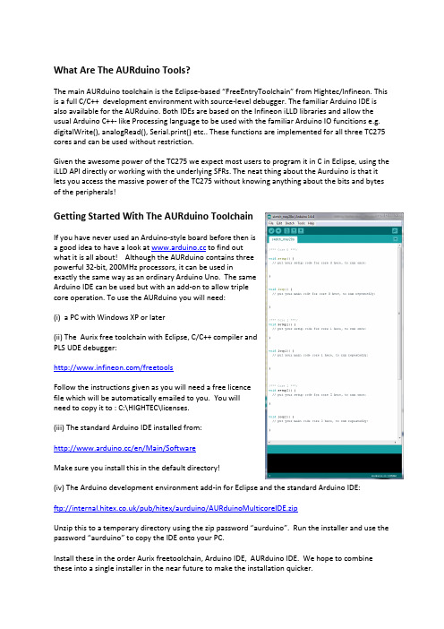
What Are The AURduino Tools?The main AURduino toolchain is the Eclipse-based “FreeEntryToolchain” from Hightec/Infineon. This is a full C/C++ development environment with source-level debugger. The familiar Arduino IDE is also available for the AURduino. Both IDEs are based on the Infineon iLLD libraries and allow the usual Arduino C++- like Processing language to be used with the familiar Arduino IO funcitions e.g. digitalWrite(), analogRead(), Serial.print() etc.. These functions are implemented for all three TC275 cores and can be used without restriction.Given the awesome power of the TC275 we expect most users to program it in C in Eclipse, using the iLLD API directly or working with the underlying SFRs. The neat thing about the Aurduino is that it lets you access the massive power of the TC275 without knowing anything about the bits and bytes of the peripherals!Getting Started With The AURduino ToolchainIf you have never used an Arduino-style board before then isa good idea to have a look at to find outwhat it is all about! Although the AURduino contains threepowerful 32-bit, 200MHz processors, it can be used inexactly the same way as an ordinary Arduino Uno. The sameArduino IDE can be used but with an add-on to allow triplecore operation. To use the AURduino you will need:(i) a PC with Windows XP or later(ii) The Aurix free toolchain with Eclipse, C/C++ compiler andPLS UDE debugger:/freetoolsFollow the instructions given as you will need a free licencefile which will be automatically emailed to you. You willneed to copy it to : C:\HIGHTEC\licenses.(iii) The standard Arduino IDE installed from:/en/Main/SoftwareMake sure you install this in the default directory!(iv) The Arduino development environment add-in for Eclipse and the standard Arduino IDE:ftp:///pub/hitex/aurduino/AURduinoMulticoreIDE.zipUnzip this to a temporary directory using the zip password “aurduino”. Run the installer and use the password “aurduino” to copy the IDE onto your PC.Install these in the order Aurix freetoolchain, Arduino IDE, AURduino IDE. We hope to combine these into a single installer in the near future to make the installation quicker.Using The AURduinoOnce all of the above packages have been installed, use the AURduino just like any other Arduino except that you have three processors to play with rather than just one. Processor core 0 will run setup() and loop() with processor cores 1 and 2 running setup1()/setup2() and loop1()/loop2(). There are no special measures required to write triple-core programs but make sure that that you do not try to use the same peripheral with two different cores at the same time. Whilst nothing nasty will happen, your programs will probably just not work properly! Each core is basically identical except that cores 1 and 2 are about 20% faster than core 0, having an extra pipeline stage. They all can use the same Arduino Processing language functions.Remember to press the reset button on the AURduino to make it run the new program.Using The Eclipse IDEIf you want to use the Eclipse environment, start the toolchain with the icon. When prompted, open the workspace at:C:\Hitex\AURduinoIDEUser\AURduinoIDE\EclipseThe default project is AurduinoMulticoreUser:Arduino-style sketches are stored in the Sketches directory. The default sketch “Empty.cpp” is a simple program that uses all three cores. You can overwrite the statements we used with your own.To get your programs into the AURduino, use the PLS UDE debuggerOpen the workspace“C:\Hitex\AURduinoIDE\Eclipse\AurduinoMulticoreUser\.ude\UDEDefEclipseWorkspace.wsx.”The program will automatically load. You can run it by clicking the icon and stop it with the icon. To reset the program, use the icon. You can find more information on using the Eclipse tools and the PLS UDE debugger in the guide supplied with the FreeToolChain.Getting HelpIf you need help, there is a new on-line forum at /.The hardware user manual with the pinouts is at /index.php?id=3650.。
AUR°EL RX MID 3V 超高频ASK接收器说明书
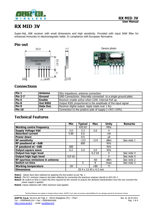
Technical features are subject to change without notice. AUR°EL S.p.A does not assume responsibilities for any damage caused by the device’s misuseRX MID 3VSuper-Het, ASK receiver with small dimensions and high sensitivity. Provided with input SAW filter for enhanced immunity to electromagnetic helds. In compliance with European NormativePin-out4,2Device photoConnectionsPin 1 Antenna 50Ω impedence, antenna connectionPin 2-7 Ground GND Connections: Internally connected to a single ground plate. Pin 6 Enable Receiver enable active when LOW. Internal Pull up.Pin 8 Out RSSI Output RSSI proportional to the amplitude of the input signal Pin 9 Data Out. Receiver digital output. Apply loads over 1 K ΩPin 10+VConnection to the positive pole of supply (+3V3 ±10%)Technical FeaturesMin Typical Max Unity Remarks Working centre frequency 433.92 MHzSupply Voltage Vdd 3.0 3.3 3.6 V Absorbed current 5.80 6.0 mA Power down 0.5 uARF sensitivity-113 -114 dBm See note 1RF passband at –3dB 600 KHz IF passband at –3dB 300 KHz Output square wave 0.2 2.0 3.0 KHzOutput low logic level 0.2 Vd V See note 4 Output high logic level0.8 Vd V See note 4 RF spurious emissions in antenna -60 dBm See note 2 Switch-on time5 8 msec See note 3Working temperature -20+80 °C Dimensions25.4 x 12.43 x 4.2 mmNote1: Values have been obtained by applying the test system as per Fig. 1.Note2: The R.F. emission measure has been obtained by connecting the spectrum analyser directly to RX’s Pin 3.Note3: By switch-on time is meant the time required by the receiver to acquire the declared characteristics from the very moment thepower supply is applied.Note4: Values obtained with 10K Ω maximum load applied.The declared technical features have been obtained by applying the following test system:Fig. 1 – Measurement of sensitivity.Enable pinPin 6 is used to set the receiver in power down mode, this allows a lower current consumption when the RF signal is not received. Typical current consumption in power-down mode is 0.5 uA.Timing needed to have a correct signal reception, once out from the power down mode, is 5mS; while if device is powered for a first time, switch-on time is 50mS.The module is on when enable pin is connected to GROUND, it’s sufficient do not connect it to set the power-down mode.Device usageIn order to obtain the performances described in the technical specifications and to comply with the operating conditions which characterize the Certification, the receiver has to be fitted on a printed circuit, considering what follows:3,3 Vdc supply:1. The receiver must be supplied by a very low voltage source, safety protected against short circuits.2. Maximum voltage variations allowed: ± 0,30 V.3. De-coupling, next to the receiver, by means of a minimum 100.000 pF ceramic capacitor.Ground:1. It must surround at the best the welding area of the receiver. The circuit must be double layer, withthroughout vias to the ground planes, approximately each 15 mm.2. It must be properly dimensioned, specially in the antenna connection area, in case a radiating whipFig.2 - Suggested lay-out for the device correct usage .50 Ohm line:1.It must be the shortest as possible.2.1,8 mm wide for 1 mm thick FR4 printed circuits and 2,9 mm wide for 1,6 mm thick FR4 printed circuits.On the same side, it must be kept 2 mm away from the ground circuit.3.On the opposite side a ground circuit area must be present.Antenna connection:1. It may be utilized as the direct connection point for the radiating whip antenna.2. It can bear the connection of the central wire of a 50 Ω coaxial cable. Be sure that the braid is welded tothe ground in a close point.Antenna1. A whip antenna, 16,5 mm long and approximately 1 mm dia, brass or copper wire made, must beconnected to the RF input of the receiver.2.The antenna body must be keep straight as much as possible and it must be free from other circuits ormetal parts (5 cm minimum suggested distance.)3.It can be utilized both vertically or horizontally, provided that the connection point between antenna andreceiver input, is surrounded by a good ground plane.N.B:As an alternative to the a.m. antenna it is possible to utilize the whip model manufactured by AUR°EL (see related Data Sheet and Application Notes).By fitting whips too different from the described ones, the EEC Certification is not assured.Other components:1.Keep the receiver separate from all other components of the circuit (more than 5 mm).2.Keep particularly far away and shielded all microprocessors and their clock circuits.3.Do not fit components around the 50 Ohm line. At least keep them at 5 mm distance.If the Antenna Connection is directly used for a radiating whip connection, keep at least a 5 cm radius free area. In case of coaxial cable connection, then 5 mm radius will suffice.Reference RulesRX MID 3V receiver is EEC certified and in particular it complies with the European Rules EN 300220-3 V2.12 in class 2, and EN 301 489 V1.4.1 for class 1. The equipment has been tested according to rule EN 60950and it can be utilized inside a special insulated housing that assures the compliance with the above mentioned rule. The receiver must be supplied by a very low voltage source, safety protected against short circuits. The use of the receiver module is foreseen inside housings that assure the overcoming of the rule EN 61000-4-2not directly applicable to the module itself. In particular, it is at the user’s care the insulation of the external antenna connection, and of the antenna itself since the RF output of the receiver is not built to directly bear the electrostatic charges foreseen by the a.m. rules.“RSSI” Output pin 8In fig 3 it is reported grafically the behaviour of the voltage at the RSSI output in function of the power of the input signal. Measure has been made with 20KHz deviation to the RF signal and square wave modulation 1KHz drawn directly from a signal generator with impedance probe of 10MOhm.Fig. 3 - RSSI level according to RF power receivedReference curvesIn fig 4 it is reported the behaviour of module supply current in function of Power supplyFig. 4 – Supply current – power supplyIn fig 5 it is reported the behaviour of receiver sensitivity in function of temperature. Values are referred to the nominal power supply of 3.3Volt, there are no difference with nominal power of 3.0Volt.Fig. 5 – Sensitivity - temperature。
【早操音乐编辑神器】之Adobe Audition 录音简单操作说明
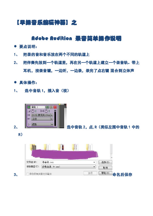
【早操音乐编辑神器】之
Adobe Audition 录音简单操作说明
●要点说明:
1、把录的音和音乐放在两个不同的轨道上
2、把伴奏先放到一个轨道里,再在另一个轨道上建立一个录音轨。
带上
耳机,按录音键,一边听,一边录,录完了点右键混合到立体声
●具体操作:
1、选中音轨1,插入音(视)
2、选中音轨2,点,R(类似左图中音轨1中的
R)
3、命名后保存
4、录的时候就点这个红色的点点吧
(录制画面如图)
5、点混音器,调音量。
拖动正在
播放的地方的推子来调节伴奏和人声的音量
6、点这个小三角形(绿色部分)试听音乐效果
7、调至合适的音量后,回到主群组,在音轨上(此处为音轨2)右键单
击,在出现的白底窗口中选中“混缩到新文件”,把鼠标箭头放在上面,出现另一个选项,选择“会话中的主控输出(立体声)”等待混缩完成。
8、混缩完成后,出现如图
界面。
9、左键单击窗口最左上角的“文件”选项,选择“另存为……”
10、对文件进行重命名,保
存类型选“选择MP3PRO?(FhG)mp3”格式,确认后保存。
试听效果吧……。
阿尔卡特朗讯4019型数字话机用户快速参考手册概要
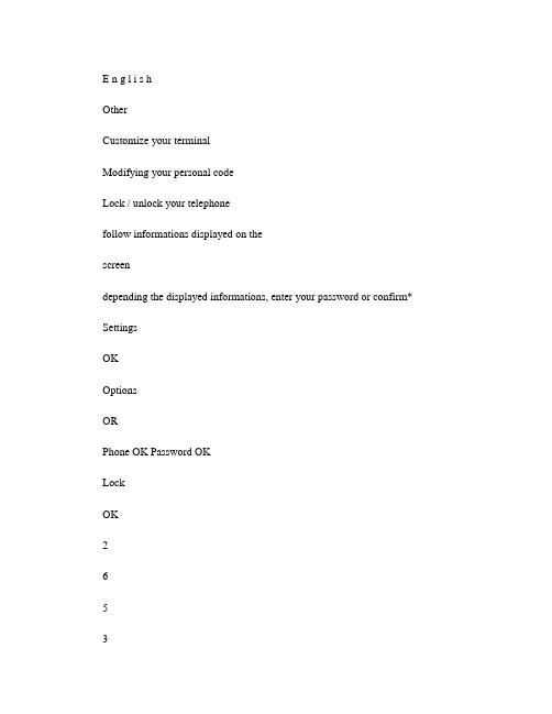
E n g l i s hOtherCustomize your terminalModifying your personal codeLock / unlock your telephonefollow informations displayed on thescreendepending the displayed informations, enter your password or confirm* SettingsOKOptionsORPhone OK Password OKLockOK2653a b c d e f k m noAdjusting the audio functions Adjusting screen brightnessUsing your telephoneIdentify the terminal you are on Making a calladjust ringing (melody, volume, mode,... by following instructions displayed on the screento return to the home page (long press increase or decrease thecontrastapplyto return to the home page (long pressdisplays your telephone numberto return to the home page (long presslift the receiver hands freeprogrammed linekeycalling from your personaldirectorydial directly the number for yourcallTo make an external call, dial the outside line access code before dialling your correspondent's number.SettingsOK Phone OKRinging OKSettingsOK Phone OKContrastOKOROKWhoamIOKOROROROKOR2653ab cde fk m no EnA l c a t e l -L u c e n t I P T o u c h 4018 HandsetAudio keysFunction keysHang-up key: to terminate a call.Hands-free/Loudspeaker Key: to make or answer a call without lif-ting the receiver (Alcatel-Lucent IP Touch 4008/IP Touch 4018 .•lit in hands-free mode or headset mode; (short press.•flashing in loudspeaker mode (long press.Intercom/Mute key:•During a conversation: press this key so that yourcorrespondent can no longer hear you.•Terminal idle: press this key to answer calls automaticallywithout picking up the receiver.To adjust the loudspeaker or handset volume up or downMessaging key to access various mail servicesIf the key flashes, a new voice message or a new text message has been received.'Redial' key : To access the 'Redial' function .NavigationUp-down navigator: used to navigate around the home page, through the menus or in a text zone when entering characters.The home page consists of:•Information on the status of the set (setlocked, call forward, etc.•Date and time•Set programming and configurationfunctionsOK key: used to validate your choices and options while programming or configu-ring.Back/Exit key: to return to previous menu (short press or return to first screen (long press. You can also use this key to correct a character you entered.WhoamILockSettingsOKFunction keys and programmable keysGuide key: Use to obtain information on the pre-programmed keys or to access the set programming or configuration.Phone book key : Phone book key to access your personal phone book (short press or to make a call by name (long press or press twice.Pre-programmed function keys and programmable key Lit when the function associated with the key is activated. The 6-key block consists of:two line keys,one 'immediate forwarding or cancel call-forward' key, one 'conference' key, one 'transfer' key,one direct call key to programme.Alphanumeric keypadTo avoid accidentally damaging the set telephone line connector, make sure you position the cord correctly in the compartment intended for this purpose.A l c a t e l -L u c e n t I P T o u c h 4008 / 4018 P h o n e & 4019 D i g i t a l P h on e w w w .a l c a t e l -l u c e n t .c o mReceiving a callRediallingMake a call-back request to a busy numberVoice message serviceConsulting your voice mailboxIf the key flashes, a new voice message or a new text message has been received.Divert your calls to another numberDivert your calls to another numberlift the receiverhands free (IP Touch 4008/4018press the key for the line thatis lit up(AIP Touch 4008/4018last number redialthe number you are calling isbusypress the key next to 'consult voice ortext message'follow informations displayed on the screenpress the 'call forward' function key dial the destination numberselect the function associated with 'immediate forwarding'apply*dial the destination number press the ok key if programming is not automatically recorded*OROR¤CallbackOKOK2653ab cde fk m no OR Forward OK OKOK2653ab cde fk m noOKDiverting calls to your voice mailboxWhen you return, cancel all diversionsDuring a conversationSending DTMF signalsDuring a conversation you sometimes have to send DTMF signals, such as with a voice server, an automated attendant or a remotely consulted answering machine. The function is automatically cancelled when you hang up.Calling a second person during a conversationDuring a conversation, to call a second person.Transferring a callDuring a conversation, to transfer the call to another number:select the function associated with'immediate forwarding'press the OK key if programming is not automatically recorded*.press the 'call forward' function keyif necessary, confirm cancellation of thediversionselect the function associated with 'emit in voicefrequencies'the first call is on holddial directly the number for your call number tobe called'transfer' programmed key ForwardOKOKOKORForward OK Cancelfwd.OK¤MFcodeORSend DTMF OK2653ab cde fk m no 2653ab cde fk m no ORTransfer OKThree-way conferenceDuring a conversation, a second call is on hold.cancel conference and return to first correspondentDirectoryUsing call by name*You enter your contact's name in predictive text mode. In this mode, enter each letter of the name by pressing only once on the key with this letter.Program the keys in the personal phone bookMake a call using the personal phone bookGuarantee and clausesThis document describes the services offered by the Alcatel-Lucent IP Touch4008/4018 Phone and 4019 Digital Phone connected to an Alcatel-Lucent OmniPCX Office or Alcatel-Lucent OmniPCX Enterprise Communication Server system. For more information, see the user manual for your Alcatel-Lucent IP Touch 4008/4018 Phone(IP set or 4019 Digital Phone (digital set. Contact your installer.Warning: never place your telephone in contact with water. To clean your telephone, you may however use a damp soft cloth. Never use solvents (trichlorethylene, acetone, etc. which may damage the plastic parts of your telephone. Never spray it with cleaning products.The ear piece and microphone area of the handset may attract metallic objects that may be dangerous for the ear.The wording is not contractual and may be subject to change. Some functions of your telephone are controlled by a software key and the configuration of the unit.EC countries: we, Alcatel-Lucent Enterprise , declare that the Alcatel-Lucent IP Touch 4008/4018 Phone and 4019 Digital Phone products comply with the essential demands of Directive 1999/5/CE of the European Parliament and Council. A copy of the original of this declaration of compliance can be obtained from your installer.* Depending on your telephone system, contact your installer or consult the appropriate User Guide.Collection of these products at the end of their product life must be done selectively.Alcatel, Lucent, Alcatel-Lucent and the Alcatel-Lucent logo are trademarks of Alcatel-Lucent. All other trademarks are the property of their respective owners. The informationpresented is subject to change without notice. Alcatel-Lucent assumes no responsibility for inaccuracies contained herein. Copyright © 2007 Alcatel-Lucent. All rights reserved.“conference” programmed key hang up on all corresponden t“conference” programmed keylong pressenter the first letters of the name select the name from thedisplayed listfollowinformations displayed on thescreenpress and release select anentry in the directory (0-9*press and release press the programmed key directly (0 to 9select the contact to callstart the callOR¤Conference OKOREnd conference OKOK*OK2653ab cde fk m no OROK‡3GV19008BSAB010728ÔÎ̉。
阿尔卡特功能话机操作手册
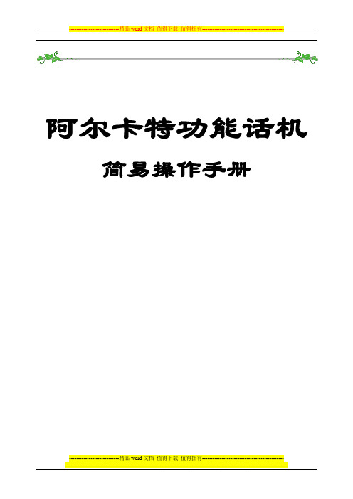
阿尔卡特功能话机简易操作手册动态功能显示屏可程序功能键及固定功能键注:呼叫图标因话机的型号不同有所差异4305功能键:外线保留外线保留外线保留外线保留重拨外线设定自动应答功能设定开/关机外线故障HOLDCall开/关机 用于开机(日间模式)/关机(夜间模式)功能设定设定系统功能如分机等级自动应答当来话会自动接电话(使用耳机或免提对讲)HOLD 当按动态键OnHold时会将外线保留于此,接回可按HOLD键外线故障当外线故障时会显示,按此键查询哪一外线故障外线群当外线满时,会点亮重拨按此键会将最后拨出之内线或外线重拨一次外线保留保留外线来话,保留时灯亮,再按时接回Call 显示有外线呼叫当来话时会自动接电话(耳机或免持对讲),取消再按一次显示功能启动注:呼叫图标因话机的型号不同有所差异注:呼叫图标因话机的型号不同有所差异拨内线分机(cat)Ring ReleasEntityCallBKuserFree345678按分机号码Free表示空闲按Ring呼叫分机响铃Ringin(cat)ReleasEntityCallBKuser345678与分机通话Conv(cat)ReleasEntityOnHolduser345678Busy。
E……(分机与外线通话中)Busy。
I……(分机与内线通话中)Unobt 分机未挂好Wrong number 分机号码错误内线应答按Intern内线键,即可应答内线来电,画面显示Conv分机号码,此时依情形可挂断键或作下列功能的操作,可使用的工作会亮灯指示。
Nornal wait = 1Urgent wait = 0internNextuser8011Conv(cat)OnHold Entity Releas应答外线按Next外线应答键,即可应答,画面显示Conv TRUNKNornal wait = 1Urgent wait = 0NextOnHoldConv TRUNKReleas转接外线应答外线后,按分机号码,再转接接键TransfEnqOff7Releds(cat)CallBkTransfRing789054user EnqOffFreeReleas可依实际状况拉回,先分机通话或转接退出Nornal wait = 1Urgent wait = 0NextCamp On转接退出后,屏幕显示Camp On 表示等待分机接听分机接听后,显示会自动消失,如未接听超过系统预设时间Camp On 会闪烁及响铃,需接回再依需求作其他功能过滤转接当转此通电话需征求受话者同意,再作转接的电话,在应答后,按分机号码,在按振铃,画面显示:(cat)CallBkTransfRing789054userEnqOffFreeReleas(cat)CallBkTransf789054userEnqOffFreeReleas当受话分机应答后,画面显示Conv 分机号码(cat)CallBkTransf789054user EnqOffReleasConv Broker如分机同意接听Transf 转接如分机不同意接听请按Enqoff 接回后,按Releas 键挂断 此时按Broker 切换键,可来回跟内线或外线通话转接分机后,有几种状况如下:(cat)CallBkTransfBroker789054userEnqOffReleasBusy.E Busy 。
CORDWAL操作技巧
CorelDRAW命令菜单CorelDRAW 命令菜单 使用C o r e l D R AW 的操作菜单栏,可进行创建新图形、设置美术字、打开和编辑图形文件、进行特殊效果的处理等操作。
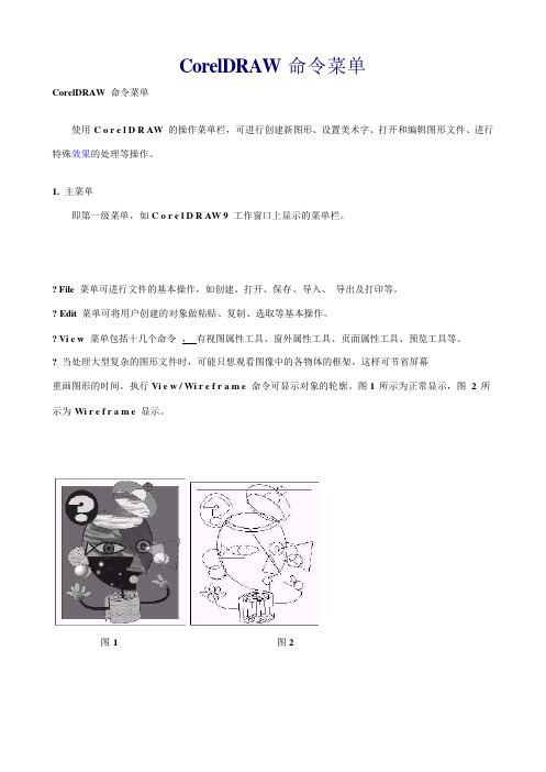
1. 主菜单 即第一级菜单,如C o r e l D R AW 9 工作窗口上显示的菜单栏。
? File 菜单可进行文件的基本操作,如创建、打开、保存、导入、导出及打印等。
? Edit 菜单可将用户创建的对象做粘贴、复制、选取等基本操作。
? Vi e w 菜单包括十几个命令,有视图属性工具、窗外属性工具、页面属性工具、预览工具等。
? 当处理大型复杂的图形文件时,可能只想观看图像中的各物体的框架,这样可节省屏幕重画图形的时间。
执行Vi e w / Wi r e f r a m e 命令可显示对象的轮廓。
图1 所示为正常显示,图 2 所示为Wi r e f r a m e 显示。
图1 图2? L a y o u t 菜单提供了多种版面设置方式,如插入、删除、定位页面、对齐网格、辅助线等精确绘图功能。
? A r r a n g e 菜单在绘制较为复杂的图形过程中,同时需要处理好几个图形对象,它们的相对位置、颜色的填充等操作能够借助A r r a n g e 菜单命令来处理。
A r r a n g e 菜单命令还提供了对象的群组功能,并可以使用本菜单来完成对象群的“对齐”、“相交”、“修剪”、“焊接”或“转换为曲线”等功能。
? E ff e c t s 菜单提供了丰富的交互式图形效果命令,可为图形增加透视点、透镜、笔刷等效果。
? B i t m a p s 菜单可以将矢量图形转换为位图文件,并可以对位图文件进行修饰、加工以创建三维、二维、艺术和肌理等效果。
? Te x t 菜单C o r e l D R AW 9 不仅是一个图形图像处理软件,它还能够直接处理文本,进行复杂的文本编辑,如建立美术文本或段落文本,还可以实现精美的图文混排等操作。
Adobe Audition使用说明
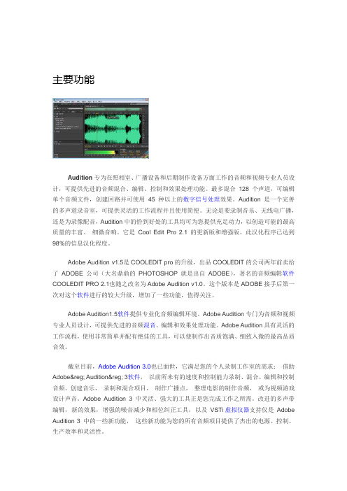
主要功能Audition专为在照相室、广播设备和后期制作设备方面工作的音频和视频专业人员设计,可提供先进的音频混合、编辑、控制和效果处理功能。
最多混合128 个声道,可编辑单个音频文件,创建回路并可使用45 种以上的数字信号处理效果。
Audition 是一个完善的多声道录音室,可提供灵活的工作流程并且使用简便。
无论是要录制音乐、无线电广播,还是为录像配音,Audition中的恰到好处的工具均可为您提供充足动力,以创造可能的最高质量的丰富、细微音响。
它是Cool Edit Pro 2.1 的更新版和增强版。
此汉化程序已达到98%的信息汉化程度。
Adobe Audition v1.5是COOLEDIT pro的升级,出品COOLEDIT的公司两年前卖给了ADOBE公司(大名鼎鼎的PHOTOSHOP就是出自ADOBE),著名的音频编辑软件COOLEDIT PRO 2.1也随之改名为Adobe Audition v1.0。
这个版本是ADOBE接手后第一次对这个软件进行的较大升级,增加了一些功能,值得关注。
Adobe Audition1.5软件提供专业化音频编辑环境。
Adobe Audition专门为音频和视频专业人员设计,可提供先进的音频混音、编辑和效果处理功能。
Adobe Audition具有灵活的工作流程,使用非常简单并配有绝佳的工具,可以使制作出音质饱满、细致入微的最高品质音效。
截至目前,Adobe Audition 3.0也已面世,它满足您的个人录制工作室的需求:借助Adobe® Audition® 3软件,以前所未有的速度和控制能力录制、混合、编辑和控制音频。
创建音乐,录制和混合项目,制作广播点,整理电影的制作音频,或为视频游戏设计声音。
Adobe Audition 3 中灵活、强大的工具正是您完成工作之所需。
改进的多声带编辑,新的效果,增强的噪音减少和相位纠正工具,以及VSTi虚拟仪器支持仅是Adobe Audition 3 中的一些新功能,这些新功能为您的所有音频项目提供了杰出的电源、控制、生产效率和灵活性。
Acura 车载音频系统操作手册说明书
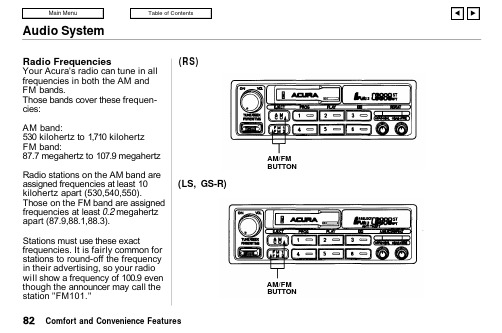
Audio SystemRadio FrequenciesYour Acura's radio can tune in all frequencies in both the AM and FM bands.Those bands cover these frequen-cies:AM band:530 kilohertz to 1,710 kilohertz FM band:87.7 megahertz to 107.9 megahertz Radio stations on the AM band are assigned frequencies at least 10kilohertz apart (530,540,550).Those on the FM band are assigned frequencies at least 0.2 megahertz apart (87.9,88.1,88.3).Stations must use these exactfrequencies. It is fairly common for stations to round-off the frequency in their advertising, so your radio will show a frequency of 100.9 even though the announcer may call the station "FM101."(RS)(LS, GS-R)Comfort and Convenience FeaturesAM/FM BUTTONAM/FMBUTTONAudio SystemOperating the Cassette Player Turn the system ON. Insert the cassette into the slot with the tape opening to the right. Push the cassette in most of the way. The drive will pull it in the rest of the way and begin to play.The or will light to show you which side of the cassette is playing.The indicates the side you inserted facing upward is now playing. To play the other side of the tape, press the PROG button.The system also has an Auto-reverse feature. It will automati-cally reverse direction when it reaches the end of the cassette.(RS)CONTINUEDComfort and Convenience FeaturesON/OFF/VOL KNOBCASSETTE SLOT TAPE DIRECTION INDICATOREJECT BUTTON PROG BUTTON PLAY BUTTON DOLBY BUTTON(LS, GS-R)ON/OFF/VOL KNOBCASSETTE SLOTTAPE DIRECTION INDICATOREJECT BUTTON PROG BUTTON PLAY BUTTON DOLBYBUTTONAudio SystemDolby ® noise reduction turns on when you insert a cassette. If the tape was not recorded with Dolby "B " noise reduction, turn it off by pressing the button.To remove the cassette from the drive, press the EJECT button. The system automatically ejects the cassette whenever you turn off the system or the ignition switch.(RS)(LS, GS-R)Comfort and Convenience FeaturesFF/REW/TMS SWITCH EJECT BUTTON PROG BUTTON PLAY BUTTON DOLBY BUTTON REPEAT BUTTONFF/REW/TMS SWITCH EJECT BUTTON PROG BUTTON PLAY BUTTON DOLBY BUTTON REPEATBUTTONAudio SystemCassette Search Functions Once a cassette is playing, you can use the FF, REW, TMS, or REPEAT function to look for desired songs or passages.To rewind the tape, push the FF/REW/TMS switch down thenrelease it. You will see REW in the display. To fast forward the tape,push the switch up then release it.You will see FF displayed. To stop rewind or fast forward, press the PLAY button. If the system reaches the end of the cassette while in fast forward or rewind, it automatically stops that function,reverses direction, and begins to play.Press the REPEAT button to replay the current passage. You will see RPT displayed. When the system reaches the end of the song or passage that is being played, it automatically goes into rewind.When it senses the beginning of that passage, it goes back to play.The system will continue repeating this passage until you turn off REPEAT by pressing the button again.The TMS function lets you skip to the beginning of a song or other passage. The tape skips forward or backward, depending on which direction you push the FF/REW/TMS switch.Activate TMS by pushing the FF/REW/TMS switch and holding it until you hear a beep. If you push the switch down, you will see REW blinking in the display as the tape rewinds. If you push the switch up,you will see FF blinking in the display as the tape fast forwards.When the system senses a silent period on the tape, it goes back to PLAY mode.The REPEAT and TMS functions use silent periods on the tape to find the end of a selection. These features may not work satisfacto-rily on tapes that have almost no gap between songs, a high noise level between songs, or silent peri-ods in the middle of songs.Caring For CassettesDamaged cassettes can jam inside the drive or cause other problems.See page 90 for information on cassette care and protection.Comfort and Convenience FeaturesAudio SystemOperating the CD Changer or Player (Optional)A Compact Disc changer isavailable for your car. It holds up to six discs, providing several hours of continuous programming. You operate the CD changer with the same controls used for the radio and cassette player.Load the desired CD's in themagazine and load the magazine in the changer according to the instructions that came with the unit.Your dealer has Genuine Acura accessory in-dash CD players available that are operated by the radio controls. If you have one of these units, use the directions in this section (except for multi-disc selection) to operate it.To operate the CD changer, the ignition key must be inACCESSORY (I) or ON (II). If you are listening to a cassette tape,eject it before playing a CD.Press the CD button until "CD"appears on the display. Once in the CD mode, the system will start to play the first track of the first disc in the magazine.When that disc ends, the next disc in the magazine is loaded and played.After disc 6 has completed, the system will return to disc 1. To make your own disc selection, push one of the six preset buttons. Your selection will appear in the display and start playing.You can use the TUNE/SEEK switch while a disc is playing to select passages and change tracks.To move rapidly forward within a track, push up and hold the TUNE/SEEK switch. Push down and hold the switch to move rapidly back-ward within a track. You will hear a beep a half second after you push the switch up or down. Keeppushing the switch until you think the track has advanced or returned to the desired position. The disc will start playing when you release the switch.If you push the TUNE/SEEKswitch up and release it before you hear a beep, the system will skip forward to the beginning of the next track on that CD.If will skip backward to the begin-ning of the current track if youpush the switch down and release it.Comfort and Convenience FeaturesAudio System(RS)CONTINUEDComfort and Convenience FeaturesON/OFF/VOL KNOBRPT INDICATORTUNE/SEEK SWITCHCD BUTTONREPEAT BUTTON(LS, GS-R)ON/OFF/VOL KNOBA. SELECT INDICATORRPT INDICATORTUNE/SEEK SWITCHCD BUTTONA. SELECT/REPEAT BUTTONAudio SystemIf you push the REPEAT button on the RS model or the A. SELECT/REPEAT button on the LS and GSR models, the system willcontinuously play the track you are listening to. You will see RPT in the display.Push the switch again to turn off REPEAT mode.On LS and GS-R modelsYou can get the CD player torandomly select tracks by pressing A. SELECT/REPEAT until you see A. SELECT in the display.With this active, the system selects and plays the tracks randomly,rather than sequentially, on each disc. When the system has played all the tracks on that disc, it loads the next disc and starts to playrandomly. The system continues to select and play tracks randomly on each of the six discs until you press the A. SELECT/REPEAT button again.To turn on random play mode while the system is in the REPEAT mode,turn off REPEAT mode first by pressing the A. SELECT/REPEAT button. Then, press the buttonagain as explained above.If you change modes to radio or tape while a CD is playing, then change back to CD mode, thesame disc and track will play.If you turn off the system while a CD is playing, either with the ON-OFF/VOL knob or by turning off the ignition, the system will begin at the same disc and track when you turn itback on.If you try to select an empty slot in the magazine, the system will select and play the first track of the next disc in the magazine.To return to the radio function,press the AM/FM button.Comfort and Convenience FeaturesAudio SystemCD Error IndicationsIf you see an error indication on thedisplay, find the cause in the chartto the right. If you cannot clear theerror indication, take the car toyour Acura dealer.Comfort and Convenience FeaturesCaring for the Cassette PlayerThe cassette drive picks up dirt and oxides whenever you play a tape. This builds up over time and causes the sound quality to degrade.To prevent this, you should clean the cassette drive after every 30hours of use. Your dealer has a cleaning kit available for this purpose.After 30 hours of tape use, you will see CLEAN flashing for 5 seconds in the display when you insert atape into the tape slot. If you are already regularly cleaning the tape drive at least every 30 hours, reset the indicator by pressing the Preset 6 button while the system is in the tape operation mode. Hold the button until you hear a beep and the CLEAN indicator goes out.If you do not clean the cassette drive regularly, it may eventually become impossible to remove the deposits with a normal cleaning kit.The cassette player automatically ejects cassettes that do not play normally. If it ejects a cassette before it begins to play, it isprobably defective and should not be inserted again. You may have a cassette suddenly stop playing,reverse directions once or twice and then eject. This is normally an indication the tape is woundunevenly. It should play normally after being manually rewound.Use 100-minute or shorter cas-settes. Cassettes longer than 100minutes use thinner tape that may break or jam the drive.Look at a cassette before you insert it. If the tape is loose, tighten it by turning one of the hubs with a pencil or your finger.If the label is peeling off, do not put it in the player. It may cause the cassette to jam in the drive mecha-nism when you try to eject it.Do not leave cassettes sitting where they are exposed to high heat or humidity, such as on top of the dashboard or in the player. If a cassette is exposed to extreme heat or cold, let it reach a moderatetemperature before putting it in the player.Comfort and Convenience FeaturesCLEAN INDICATORTheft ProtectionOn LS and GS-R modelsYour car's audio system will disable itself if it is disconnected from electrical power for anyreason. To make it work again, the user must enter a specific five-digit code in the Preset buttons. Because there are hundreds of number combinations possible from five digits, making the system work without knowing the exact code is nearly impossible.You should have received two copies of a card that lists your audio system's code number and serial number. It is best to store one of these cards in a safe place at home, and to keep the other in your wallet or purse. In addition, you should write the audio system's serial number in this Owner's Manual. If you should happen to lose both cards, you must obtain the code number from your Acura dealer. To do this, you will need thesystem's serial number.If your car's battery is discon-nected or goes dead, the audio system will disable itself. If this happens, you will see "Code" in the frequency display the next time you turn on the system. Use the Preset buttons to enter the five-digit code. If it is entered correctly,the radio will start playing.If you make a mistake entering the code, do not start over or try to correct your mistake. Complete the five-digit sequence, then enter the correct code. You have three tries to enter the correct code. If you are unsuccessful in three attempts, you must then leave the system on for one hour before trying again.You will have to store your favorite stations in the Preset buttons after the system begins working. Your original settings were lost when power was disconnected.Comfort and Convenience Features。
aurcord简明操作手册
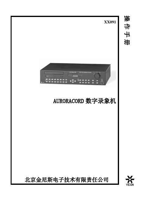
AURORACORD数字录象机
2
前面板按钮示意图
1 2 3 4 5
6 7
1键,按下用于浏览时实图象。
2键,按下用于回放录制图象,再按下暂停放像 3键,按下选择不同的显示格式,如四画面、十六画面及全画面
4键,按下冻结时实图象 5
外轮:在暂停或播放模式下,转动改变快进或到带速度
在播放模式下,选择一个播放速度,并按ENTER 键锁定,此时按你设定的播放
速度来回放,再次按ENTER 键,按正常的速度回放图象 6键(可选),用于云台予置位操作
PRESET 键,再按要选的数字键,再按PRESET 键 ENTER 键,然后按PLAY 键 7键(可选)
● ZOOM+键 镜头ZOOM IN ,ZOOM-键 镜头ZOOM OUT ● LIVE 键,云台向左,PLAY 键,云台向右 ● RECORD 键,云台向上,SPOT 键,云台向下。
Adobe Audition 1.5教程
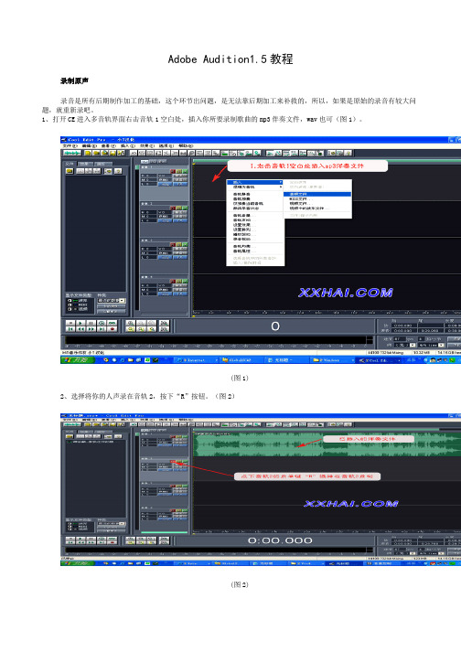
Adobe Audition1.5教程录制原声录音是所有后期制作加工的基础,这个环节出问题,是无法靠后期加工来补救的,所以,如果是原始的录音有较大问题,就重新录吧。
1、打开CE进入多音轨界面右击音轨1空白处,插入你所要录制歌曲的mp3伴奏文件,wav也可(图1)。
(图1)2、选择将你的人声录在音轨2,按下“R”按钮。
(图2)(图2)3、按下左下方的红色录音键,跟随伴奏音乐开始演唱和录制。
(图3)(图3)4、录音完毕后,可点左下方播音键进行试听,看有无严重的出错,是否要重新录制(图4)(图4)5、双击音轨2进入波形編辑界面(图5),将你录制的原始人声文件保存为mp3pro格式(图6 图7),以前的介绍中是让大家存为wav格式,其实mp3也是绝对可以的,并且可以节省大量空间。
(图5)(图6)注)需要先说明一下的是:录制时要关闭音箱,通过耳机来听伴奏,跟着伴奏进行演唱和录音,录制前,一定要调节好你的总音量及麦克音量,这点至关重要!麦克的音量最好不要超过总音量大小,略小一些为佳,因为如果麦克音量过大,会导致录出的波形成了方波,这种波形的声音是失真的,这样的波形也是无用的,无论你水平多么高超,也不可能处理出令人满意的结果的。
另:如果你的麦克总是录入从耳机中传出的伴奏音乐的声音,建议你用普通的大话筒,只要加一个大转小的接头即可直接在电脑上使用,你会发现录出的效果要干净的多。
降噪处理降噪是至关重要的一步,做的好有利于下面进一步美化你的声音,做不好就会导致声音失真,彻底破坏原声。
单单这一步就足以独辟篇幅来专门讲解,大家清楚这一点就行了。
1.点击左下方的波形水平放大按钮(带+号的两个分别为水平放大和垂直放大)放大波形,以找出一段适合用来作噪声采样波形(图8)(图8)2.点鼠标左键拖动,直至高亮区完全覆盖你所选的那一段波形(图9)。
(图9)3.右单击高亮区选“复制为新的”,将此段波形抽离出来(图10)。
(图10)4.打开“效果--噪声消除--降噪器”准备进行噪声采样(图10)。
音频CD录音机CDR950 951使用指南说明书
Audio CD RecorderCDR950/951Instructions for use •Mode d'emploi•Instrucciones de manejo •Bedienungsanleitung •Gebruiksaanwijzing •Istruzioni per l'uso •Brugsanvisning •Bruksanvisning Käyttöohje•Manual de utilização ••Instrukcja obs¬ugi•11disturbances).If your equipment does not offer digital connections, the high quality Analog-Digital-Convertor of your CD recorder will ensure very good audio performance when recordings are made from the analog input.Playback via the digital coaxial output of the CD recorder gives the best audio performance.If your equipment does not offer digital connections, the high quality Digital-Analog-Convertor of the CD recorder ensures a very good sound quality via the analog output.We advise you to always establish both digital and analog connections. In this way you can always make analog recordings when digital recording is not possible.We have described the most common ways of connecting the CD recorder. If you still have difficulties with the connections you can always contact the Philips Consumer Service desk in your country.Use the audio cables supplied. Connect the red plugs to the R sockets, and the white plugs to the L sockets.1For recording, connect cable 1between the ANALOG IN-sockets on the CD recorder and the CDR LINE- or TAPE OUT-sockets of an amplifier.Note:For recording directly from a CD player, the ANALOG INsockets of the CD recorder should be connected to the analog output of the CD player. 2For playback, connect cable 2between the ANALOG OUT-sockets on the CD recorder and the input sockets of an amplifier e.g. TAPE IN, CDR or AUX.Note:Never use the PHONO input.12DAT or DCC recorder) to the DIGITAL IN 2 socket of the recorder.Note:Your CD recorder is equipped with a digital coaxialoutput (DIGITAL OUT). This output can be used for digital playback.1Remove the dust caps from the digital optical connection.(We recommend you save the cap).2For recording, connect a fibre-optic cable 4between the digital OPTICAL IN socket of the CD recorder and the digital-optical output of a CD player.Note:Your CD recorder is equipped with a digital OPTICALoutput. This output can be used for digital playback.132Press ON/OFF.§The recorder is now in Standby mode.3Press any key to activate the recorder.Note:- The CD recorder will automatically adjust to the local mains voltage.- When the CD recorder is in the Standby mode, it is still consuming some power. If you wish to disconnect your recorder completely from the mains, press ON/OFF on the recorder front.- Place the CD recorder on a solid, vibration free surface.- Do not place the CD recorder near a source of heat or in direct sunlight.- Do not use the CD recorder under extremely damp conditions.- If the CD recorder is placed in a cabinet, make sure that a 2.5 cm space remains free on all sides of the CD recorder/player for proper ventilation.1Open the battery compartment cover.2Insert 2 batteries (“AA”, LR-6 or UM-3; as supplied) as shown.3Replace the cover.Note:We recommend you use 2 batteries of the same typeand condition.Batteries contain chemical substances, so they should be disposed of properly.。
- 1、下载文档前请自行甄别文档内容的完整性,平台不提供额外的编辑、内容补充、找答案等附加服务。
- 2、"仅部分预览"的文档,不可在线预览部分如存在完整性等问题,可反馈申请退款(可完整预览的文档不适用该条件!)。
- 3、如文档侵犯您的权益,请联系客服反馈,我们会尽快为您处理(人工客服工作时间:9:00-18:30)。
AUR-NIU网络软件目录介绍…………………………………………………………………………………………初步操作………………………………………………………………………………提供电源………………………………………………………………………………………输入密码(可选)……………………………………………………………………………检查可利用的硬盘空间…………………………………………………………………………定义和选择显示格式……………………………………………………………………………浏览磁盘状态……………………………………………………………………………………插入和弹出CD或软盘……………………………………………………………………………运行一个人为计划(可选)………………………………………………………………………清除解码器通讯失败(可选)……………………………………………………………………确认报警……………………………………………………………………………………………显示报警事件和信息………………………………………………………………………………选择一个监视器……………………………………………………………………………………控制电子水平、垂直及变焦功能…………………………………………………………………切换视频……………………………………………………………………………………………浏览时实视频………………………………………………………………………………………从磁盘上浏览视频图象……………………………………………………………………………录制音视频…………………………………………………………………………………………回放音视频…………………………………………………………………………………………附录:AUR-NIU网络软件操作说明介绍威康的AURCORACORD数字硬盘录象机是分割器及数字长延时录象机的有机结合;分割器以VICON的AUROR2000为基础;数字录象是新增的,用数字硬盘代替VCR。
AURCORD是强有利的的监控工具,对于大或者小的CCTV系统而言,AURCORD允许轻松你执行下列功能:●浏览多画面摄象机显示●从多画面显示选择摄象机●录象、浏览或同步存档视频●电子和机械水平、俯仰及镜头●输出视频图象到软盘●存档到软盘及CD●从软盘、CD-RW及硬盘中回放视频●从前面板上控制摄象机●打印报告到一个串口打印机●用PC键盘用于命名摄象机、报警及系统操作●用主计算机来控制多台AURCORACORD硬盘录象机●用AURORANET创建AURCORACORD网络及从任意一台AURCORACORD控制其它AURCORACORD录象机●定义和运行宏前面板按钮示意图1 2 3 4 56 71键,按下用于浏览时实图象。
2键,按下用于回放录制图象3键,按下选择不同的显示格式4键,按下冻结时实图象5:滚轮操作见16节6键,用于云台予置位操作PRESET 键,再按要选的数字键,再按PRESET 键ENTER键,然后按PLAY键7键,在执行云台操作时,必须按下该键,此时键镜头ZOOM IN ,ZOOM-键镜头ZOOM OUT●LIVE 键,云台向左,PLAY键,云台向右●RECORD键,云台向上,SPOT键,云台向下初步操作一.提供电源开关电源提供允许在100-240VAC,47-63HZ操作,220/110VAC可选,在电源中断时,备份电池能保护你的程序;电池的有效期为2-3年,必须通过用户更换它,在提供电源,需执行下列步骤:1.对于220VAC,用0.63A保险管代替出厂的1.25A保险管2.把电源线插入AURCORACORD电源插孔3.把电源线另一端插入220电源内二、输入密码(可选)当你第一次使用AUR面板键或者进入编程菜单时,你必须输入密码;用面板输入合适的密码并按键确认三、检测提供的磁盘空间键,屏幕上显示在你的硬盘中所剩的空间,一四、定义及选择显示格式回放模式(键上方的灯亮)提供的显示格式有全画面、四画面、九画面、16画换●按●按键在屏幕的底部显示指示,用数字键选择摄象机到你需的显示窗口内●下一个窗口将自动选择,你继续用数字键选择摄象机到该窗口内;当你不需要改变●按键主显示窗口配置:15 摄象机号CAMERA 15 摄象机字符NORMAL 优先级OFF 切换1SEC 切换延时16 切换步数DEFINE SEQUENCE LIST 切换列表SET SEQUNENCE DEFAULTS 切换初始植注:上下箭头用于选择项,按左箭头用于存盘且退出该菜单,用左箭头或数字键改变参数●在上一步中摄象机已被指派给某个窗口,你希望把摄象机指派到窗口内,可以通过改变摄象机号来实现,摄象机字符可以定义在编程中实现●摄象机更新优先级可以通过编程屏幕或上面设置的主窗口配置来改变;编程中有一节会详细讨论;如果你在主显示窗口改变设置,它在编程的有关部分同时改变,选定更新优先区域及选择高、正常;选择视频更新高的级别比选择视频正常更新级别,其视频更新要快。
“正常”设置用于浏览的图象为不重要的时候●你可以恢复切换出厂初始值(菜单的第八项),否则继续下列步骤●选择切换区域并定义合适的动作:自动手动键才进行切换关定义为不切换●选择切换驻留时间,用于定义图象从一个摄象机切换到另一个摄象机所需时间●定义摄象机切换布数●选择切换列表,如下图所示:●●键两次,然后按键完成这个显示格式窗口的配置●●●连续按(或者先按1 2 3 4 5 6 7 8 9画中画四画面六画面 16画面五.浏览磁盘状态执行下列步骤可以浏览硬盘、软盘及CD光驱状态1.进入磁盘功能如下(按面板的MENU键)在磁盘功能菜单中按数字1进入:在磁盘功能菜单中按数字2进入:在磁盘功能菜单中按数字3进入:六.插入/弹出CD或软盘插入一章新盘,首先按弹出键,移出当前盘,然后插入一张新盘弹出一张CD,首先按CD-RW光驱上的弹出键或者菜单设置中的“OPEN/CLOSE CDRW”项,然后插入一张新盘存档执行下列步骤用于存档到CD或软盘上1在磁盘功能菜单中按数字3进入:在菜单中按数字6进入:2.选择软盘功能或CD-RW 功能 3. 确认状态为“准备”状态,如果软盘上数据,用PC 机清除数据,你可以用CD-RW 磁盘功能菜单中清除CD-RW 盘中内容。
未格式化的光盘可以进行写数据,你不能格式化或清除CD-R 光盘。
4. 如果存档到CD 光盘上,请确定CD 支持的刻录速度,AURCORD 录象机光驱支持4X-16X (CD-R )及4X-10X )5. 如果要存档到CD CD-RW 设置菜单6. 光盘能同时记录所有路图象,而软盘则需要选择一个摄象机进行存档 7. 选择开始结束的时间8.选择CREAT ACHIVE 项七.运行一个人为计划通过在计划建立菜单中设置,计划能在某时自动运行,它提供了多达八个计划,在定义后你能在任何时间运行1.进入计划设置菜单(按面板的MENU键)2.按3.按4.按数字键选择一项任务八.清除解码器通讯失败清除解码器通讯失败,按并保持键,这样可以确认解码器彻底解决九.确认报警在报警状态下,报警灯闪烁且蜂鸣器响,对应摄象机的指示灯将闪烁,你可以在主监视器上或监视监视器上确认报警,按ALARM键使第一个报警摄象机为全屏幕,按ALARM键1秒种,确认这个报警并切换到下个报警摄象机,当最后报警摄象机被确认后,未发生报警前的屏幕状态将显示十.显示报警历史及状态在正常模式下(未报警时),按ALARM键,如果在时实状态下,下列屏幕将显示,摄象机号码将显示在最左列,显示摄象机标题按1-16任意键;时间及日期在第2和3列;报警类型显示在最右列。
系统提供100个报警记录报警类型:视频丢失、视频动态检测及报警借口输入及解码器报警状态显示:ON(报警发生) OFF(瞬时报警发生),ACK(操作者手动确认)ack(报警自动确认)对于回放模式,下列菜单将显示,屏幕标题根据你选择为硬盘内容的报警信息或CD-RW内容的报警;你可以浏览记录的报警录象的内容,如果没有报警内容,五秒后屏幕提示:NO DATA 如果没有视频参与,屏幕显示对应摄象机报警类型;摄象机号码从右到做排列,报警或无视频用X表示存在十一.选择一个监视器对于AURCORD系统有三个输出监视器,一个SPOT监视器,两个主监视器,SPOT监视器输模拟视频,没有进行数字处理;用主监视器实现所有功能按SPOT键触发监视器选择,SPOT监视器指示灯亮,SPOT监视器被选择;信息会出现在屏幕上十二.控制电子水平、垂直及变焦操作者能够电子变焦缩放,并能在缩放时水平、垂直浏览;如果回放模式下,你仅能电子变焦;在全屏幕下,按ZOOM+键或按ZOOM-键实现电子变焦按任意数字键退出该功能十二.冻结或释放视频图象冻结或释放视频图象,通过按FREEZE键实现;第一次按FREEZE键所有窗口的图象都被冻结,输入数字键,再按FREEZE键,释放该画面;冻结多画面能使你仅同时冻结一个画面,而保持其他画面正常十三.切换画面根据你的设置,图象可按下列模式进行切换(详见编程手册)1.自动模式:按SEQENCE键2.手动模式:按SEQENCE键再按ENTER键3.自动模式/手动模式:按SEQENCE键/按SEQENCE键再按ENTER键十四.浏览时实视频按LIVE键能浏览时实视频。
同时视频在录象,包括在时实或回放状态下从软盘上浏览视频图象PC机能够浏览图象从软盘上记录的信息;它必须为奔腾机且操作系统为WINDOWS 98/NT/XP/ME;在第一次浏览前,你必须下载VICON解码程序到你的硬盘上,然后安装它。
此时你可媒体播放器浏览视频了十五.录制音/视频视频、音频及报警信息及磁盘最后清除时间都能被记录到硬盘上;其参数见编程手册,选择要录象的视频可执行下列步骤:在正常模式下,按RECORD键,下列菜单出现按数字键选择该摄象机是否录象,*表示要录象,否则就不录象十六.回放音/视频按PLAY键回放磁盘的图象(可从硬盘/软盘及光盘来源),通过编程菜单选择播放源;同时也能从光盘及硬盘上回放音频你能在不同格式下回放图象,诸如:多画面、全画面及切换模式下等,在播放时,你也可使用电子变焦暂停;再次按PLAY键,实现暂停播放,再次按PLAY键,继续回放回放轮的使用外轮:在暂停或播放模式下,转动改变快进或到带速度在播放模式下,选择一个播放速度,并按ENTER键锁定,此时按你设定的播放速度来回放,再次按ENTER键,按正常的速度回放图象内轮:在暂停模式下,转动内轮,图象按帧回放快速回放:可以按时间点、报警快速搜索回放图象,见编程菜单内轮回放轮附录:AUR-NIU网络软件操作说明准备:系统硬件连接完毕,并正常工作计算机已安装AUR-NIU网络软件基本操作:1.在计算机桌面鼠标点击“VICONDVR”软件,下列界面将显示:主界面键功能介绍:* Full Image : 按640x480图象大小显示.* Small Image :按320x240 i图象大小显示..* Site List : 配置IP地址并连接到服务器上.* Play Back : 选择按JPEG 格式或UMF格式回放* Video Setup :配置视频设置.* Record Setup : 配置本地录象的文件名及位置.* Image Record :按JPEG格式本地录象.* Video Record : 开始/停止时实录象.* Disk Space : 检查硬盘剩余空间.* Change Password :改变当前密码.* Help : 帮助文件* Double Key : 用于回放硬盘录象机的视频,与硬盘录象机回放轮一样(必须按下此健)2.在主界面按SITE LIST键,下列界面显示在NAME后输入VICON,在IP ADDRESS后输入10.30.14.19,并按CONNECT,下面界面见显示:在USER后输入ADMIN,PASSWORD后输入VICON,并按OK键确认,图象将显示,且主界面下部的按键将激活,其键的位置及功能与录象机前面板的完全一致3.退出;在主界面按其右上角的“X”,软件退出。
