02-Transistors and Layout
Layout面试试题
LVDS——
crosstalk interference——
Micro-Strip——
6.谈一下Layout工程师在项目开发团队中的作用和关键性(10分)
列出PCB制版文件的工艺要求和注意事项?(20分)
3.PCB连板设计时,会增加,在此部件上会有Mark点给SMT定位用。比较一下邮票孔和V-Cut的优劣(10分)
4.PADS快捷键考核(10分)
UMM——
“F4”——
“Ctrl+E+C”——
5.翻译(10分):
Toppaste——
layout面试试题姓名成绩简述用eda软件orcadpads进行产品设计到调试出样机的整个过程各环节要注意哪些问题
Layout面试试题
姓名成绩
1.简述用EDA软件(OrCAD、Pads)进行产品设计到调试出样机的整个过程,各环节要注意哪些问题?(40分)
2.PCB的表面处理方式有哪些?1OZ铜厚相当于um或mil?
DI02 组装指南说明书
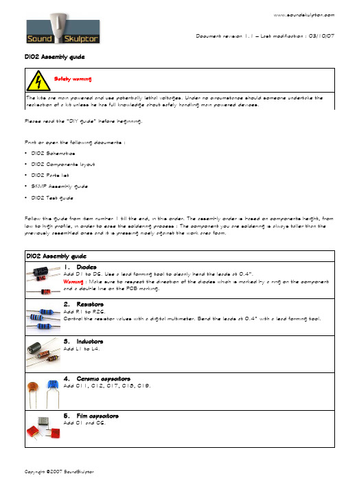
DI02 Assembly guideSafety warningThe kits are main powered and use potentially lethal voltages. Under no circumstance should someone undertake the realisation of a kit unless he has full knowledge about safely handling main powered devices.Please read the “DIY guide” before beginning.Print or open the following documents :•DI02 Schematics•DI02 Components layout•DI02 Parts list•SKMP Assembly guide•DI02 Test guideFollow this guide from item number 1 till the end, in this order. The assembly order is based on components height, from low to high profile, in order to ease the soldering process : The component you are soldering is always taller than the previously assembled ones and it is pressing nicely against the work area foam.DI02 Assembly guide1.DiodesAdd D1 to D6. Use a lead forming tool to cleanly bend the leads at 0.4”.Warning : Make sure to respect the direction of the diodes which is marked by a ring on the componentand a double line on the PCB marking.2.ResistorsAdd R1 to R26.Control the resistor values with a digital multimeter. Bend the leads at 0.4” with a lead forming tool.3.InductorsAdd L1 to L4.4.Ceramic capacitorsAdd C11, C12, C17, C18, C19.5.Film capacitorsAdd C1 and C6.DI02 Assembly guide6.TransistorsAdd Q1, Q2 and Q3,Q4.Warning : Watch out the transistor direction.7.ConnectorsAdd CN1 to CN4. Start soldering one pin, check the position, then solder the other pins.Warning : Check the position of the slot, it must not be mounted backwards.8.Small electrolytic capacitorsAdd C2, C7, C15, C16.Solder one lead first, adjust verticality then solder the second lead.Warning : The +lead must go into the +hole. Do not reverse (they may explode !)9.TerminalsAdd CN5 and CN6. They must be assembled together with the lateral dovetail. Screw down the terminalsall the way before soldering.Warning : the wire apertures should point towards the outside of the board !10.Jack socketsAdd J1 and J2. The position of the sockets is critical for a good front-plate matching. They must sit flaton the PCB. Press firmly the socket on the PCB and solder one of the pins. Check position then solderthe other pins.11.RegulatorsAdd U1 and U2. Insert them as far down as possible, solder one pin, adjust theverticality, then solder the two other pins.Warning : Watch out the direction, the metal tab at the back of the device issymbolized by a double line on the PCB marking. U1 and U2 are different, do not mixthem up.rge electrolyticsAdd C3, C4, C8, C9, C5, C10, C13, C14.Solder one lead first, adjust verticality then solder the second lead.Warning : The +lead must go into the +hole. Do not reverse (they will explode !)13.HeatsinksClip the heatsinks on the two regulators.DI02 Assembly guideAfter your board has been stuffed, brush the solder side with a hard tooth brush to remove any remaining solder bits. Make a full visual check. Any missing component on the board ? Any remaining component in the box ?Your DI02 is now ready for testing. Please follow instructions in the “DI02 test guide” document.。
Android动画之LayoutTransition布局动画

Android动画之LayoutTransition布局动画1 LayoutTransition 概述通过对视图动画和属性动画的学习,我们现在可以对一个view进行动画操作,但是如何在添加view,删除view,显示view,隐藏view时给相应view和受影响的其他view添加动画,不太容易做。
如果不添加动画,单纯的使用setVisible会显得很突兀。
如果只是对受到影响的view添加动画,可以通过设置view的高度使之显示和隐藏,还可以利用ScrollView通过滚动隐藏和显示动画,但其他受影响的view则比较难处理,布局动画LayoutTransition 就可以很好地完成这个功能。
来自Developer 网站关于LayoutTransition概述:LayoutTransition字面翻译是布局的过渡也就是布局动画,这个类可以实现ViewGroup的布局改变时自动执行动画,LayoutTransition 从api11开始提供。
给ViewGroup设置动画很简单,只需要生成一个LayoutTransition实例,然后调用ViewGroup的setLayoutTransition(LayoutTransition)函数就可以了。
当设置了布局动画的ViewGroup添加或者删除内部view时就会触发动画。
如果要设置定制的动画,需要调用setAnimator(方法。
布局动画由两种状态的改变导致执行四种不同的动画,两种状态的改变分别是view被添加到ViewGroup(或者变得可见VISIBILITY),view被移除ViewGroup(或者不可见),所以设置View可见或者不可见也将触发布局动画添加和删除动画的逻辑( GONE and VISIBLE)。
四种不同的动画分别是(api11中添加):•APPEARING:view被添加(可见)到ViewGroup会触发的动画。
•DISAPPEARING :view被移除(不可见)ViewGroup会触发的动画。
lay out camme disegno meccanico.意思-概述说明以及解释

lay out camme disegno meccanico.意思-概述说明以及解释1.引言1.1 概述1.1概述在机械工程领域,图纸是传递设计和制造信息的重要工具之一。
其中,机械设计图纸(camme disegno meccanico)是一种用于准确描述和传达机械产品的三维形状、尺寸、材料和制造要求的技术文件。
它不仅仅是一张平面图,更是一个复杂的系统,其中包含了许多细节和规范。
图纸的布局(lay out)是指为了清晰、准确地表达设计意图,按照一定的规范和规则将图形、文字和符号排列在图纸上的过程。
图纸的布局对于解读和使用图纸具有重要意义,它能够提供清晰的信息传达和方便的理解。
在进行图纸布局时,需要考虑以下几个方面:首先,要遵循一定的布局规则和标准。
图纸布局需要符合国际、国家或行业相关的标准,如ISO、GB等。
这些标准规定了图纸的尺寸、边框、标题、符号等方面的要求,确保了图纸的统一性和可读性。
其次,要根据图纸的内容和需求进行合理的排列。
不同类型的图纸可能需要不同的布局方式,如装配图、零件图、工艺图等。
合理的图纸布局能够优化图纸的使用效果,提高设计和制造的效率。
此外,要注意图纸的可读性和易懂性。
清晰的字体、准确的尺寸标注、明确的图形符号等都是保证图纸可读性的重要因素。
在布局过程中,需要合理安排文字和符号的位置,避免拥挤或混乱,使图纸更易于理解和解读。
总之,图纸布局是机械设计中不可忽视的一部分。
它不仅可以提供清晰、准确的设计信息,还能够提高设计和制造的效率。
因此,掌握图纸布局的基本原则和技巧对于机械设计人员来说是非常重要的。
在接下来的文章中,我们将详细探讨图纸布局的概念解释和设计原则,以期为读者提供有益的指导和帮助。
1.2文章结构在本文结构部分,文章将会按照以下方式展开:首先,我们将通过引言来介绍本文的主题。
引言部分将包括以下内容:概述、文章结构和目的。
在概述中,我们将简要介绍camme disegno meccanico的概念和背景。
凯镭思互调仪操作手册(中英文)
F
升级标题页添加Summitek/Triasx 商标和联系方式
22/06/09
(IR7317)
Updates. New state editor GUI. (IR7402)
G
升级,新版本的测试设置文件编辑器用户界面
(IR7402)
17/08/09
Authorisation 批准
PDS PDS PDS TN
B
removed.
17/04/08
升级1.3.2和1.3.5 删除USB窗口
Changes to section 1.5 by adding report number to the state
C
editor GUI.
16/05/08
升级1.5在测试设置文件编辑器中添加报告编号
Changes to AC specifications in section 1.2 and section
WA R N I N G- RF HAZARD 警告—射频危害
This equipment is designed for use in association with radio frequency (RF) radiating systems and is capable of producing up to 50W of RF power in the 800 to 2200 MHz region. Users are reminded that proper precautions must be taken to minimise exposure to these RF fields to the recommended limits. Please pay particular care to the following areas: 此设备设计用于无线电射频(RF)发射系统,能够在800至2200兆赫的射频区域内 产生高达50瓦的射频功率(RF)。用户应注意,必须采取适当的预防措施,尽量 减少暴露在射频区域里,保持在建议的范围内。请特别注意以下几个方面:
LAYOUT详解2
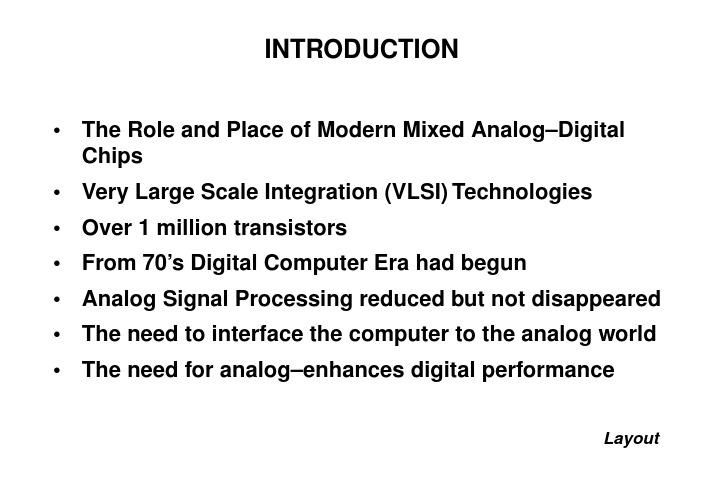
INTRODUCTION•The Role and Place of Modern Mixed Analog–Digital Chips•Very Large Scale Integration (VLSI) Technologies •Over 1 million transistors•From 70’s Digital Computer Era had begun•Analog Signal Processing reduced but not disappeared •The need to interface the computer to the analog world •The need for analog–enhances digital performanceLayoutTHE NEED TO INTERFACE THE COMPUTER TOTHE ANALOG WORLD•Computers work in the real word•Automobile•Radio, computerized engine control, safety, navigation aids, etc.•Cellular telephony•Transmission and reception of both analog and digital signals•A/D and D/A convertersLayoutTHE NEED TO INTERFACE THE COMPUTER TOTHE ANALOG WORLD•Pre–Post Conversion signal condition•Amplification, filtering for antialiasing or smoothing, sampling, holding, multiplexing etc.•Direct signal processing without A/D conversion •Medium SNR systems, high speed, low power •Interface with sensors•Receiving antennas, transmission lines,•Drive for attuators•Transmitting antennas, transmission linesLayoutTHE NEED TO INTERFACE THE COMPUTER TOTHE ANALOG WORLD•MAD circuits have been realized in metal–oxide semiconductor (MOS) technology•Precision ratio capacitor arrays•Internally compensated MOS operational amplifiers •High performances A/D converters•High performances Switched–Capacitor filters •Continuous time filters•PCM encoders–decodersLayoutTHE NEED FOR ANALOG-ENHANCED DIGITALPERFORMANCE•Analog circuits make possible the high performance of digital systems•Hard disk drive•Digital communication links•High speed digital circuits are analog in nature•Clock recovery circuits•PLL•Charge pumpsLayoutADVANTAGE OF MIXING ANALOG AND DIGITAL CIRCUITS ON THE SAME CHIP•The size of the system is reduced•The speed of the operation can be increased•The power dissipation is decreased•The design flexibility is increased –> high # of channels •The reliability is increased•The system cost is reducedLayoutAPPLICATIONS OF MAD CHIPS•Telecommunications•Consumer electronics•Computer and related equipment•Multimedia•Automotive systems•Biomedical instrumentation•RoboticsLayoutPROBLEMS IN THE DESIGN OF MAD CIRCUITS•Analog circuits are critical to design•Analog voltages are small signals (µV) near digital circuits (V)•On chip interferences•Analog circuits are not amenable to standardization •For analog circuits design automation is not possible •Testing•Mixed circuit designers are not easy to findLayoutMECHANISM AND EFFECT OF NOISE COUPLING •VLSI MAD chips consist of several subsystems whichmust be kept from interfering with each other •Sharing of common substrate•Sharing of common connections to the external word •Parasitic coupling from inductance and resistance of power supply and ground wires•Coupling from substrate•Coupling from protection diodes•Coupling from parasitic cap. of adjacent elementsLayoutMECHANISM AND EFFECT OF NOISE COUPLING •Voltages and currents switching cause noise•This noise will increase as:•Magnitude of switching events increase•Number of switching events increase•Frequency of switching events increase•Differential ECL•ECL•TTL•CMOSLayoutTECHNIQUES FOR NOISE REDUCTION•Design system solution•Shielding•Packaging•Chip floorplanning•Chip wiringLayoutSYSTEM SOLUTIONSEven pure CMOS logic design are being limited by crosstalk and inductive switching noise problemsAdding any circuitry with less noise margin than CMOS circuitsis very difficult•Separate IC’s mounted in hybrid packages or Multi–Chip Module (MCM)•Correct timing of signals•Comparators and sampling circuits do not compare or sample when large digital driver switch•Use fully differential circuits when possible•Use of special logic circuitsLayoutLAYOUT SOLUTIONS•Stop thinking of power supply lines and grounds as perfect conductors•Avoid common power supply or ground buses •Use of bypass capacitors inside and outside•Pay attention to the resonant frequency•Also analog circuits require different power supply •VDDDR1, VDDDR2, GNDDR1, GNDDR2, (PAD RING)•VDDDC1, VDDDC2, GNDDC1, GNDDC2, (CORE)•VDDA1, VDDA2,.. GNDA1, GNDA2,.. VSUB1, VSUB2,..LayoutLAYOUT SOLUTIONS•Assign bonding pads wisely•The package bonding diagram should be anticipated•Use several pads in parallel for power supply and ground •Make power supply lines and ground wide •Lines as wide as 100µm•Use of less resistive metal layer (Metal2)•Use of star VDDLayoutLayoutSUBSTRATE COUPLING•Consider substrate coupling carefully and guardagainst itSHIELDS•Shield all sensitive circuits, devices and interconnections lines•Use of metal-1 layer as digital inteferences shield •Use of well as substrate shieldLayoutLAYOUT SOLUTIONS•Avoid proximities of circuits, devices or interconnection lines that can interfere with each otherLayoutLayoutLayoutLayoutFLOORPLAN SC CIRCUITSLayoutMICROCHIPLayoutLayoutBONDING 1•Bad performance•Current in digital section •Voltage across the inductance •Resonance frequency LC can equal the clock frequency •Transistor level simulation!!!i C dv dt ------=v L di dt----=BONDING 2•Improved connection•Addition of bypass capacitor to avoid resonance frequencyLayoutBONDING 3•Best solution•CostLayoutFLOORPLANLayoutGUARD RINGSLayoutMAD EXAMPLE 1LayoutMAD EXAMPLE 2Layout。
2--Layout editor

33
Exercise 2
Create a technology library (name: my_tech) Create a design library (name: my_design) Create attachment between the 2 library (design attach to technology )
75
Layer Orientation
一般使用水平,垂直,或90度翻转
77
Create pin
Auto pin 适用于在 path 上打
pin,pin 和 path 是同一个 layer; Create pin from label 适用于已 打过 label 的场合。
78
Auto pin
84
以master中的mux2的layout为例
mux2
Level 0
nand
M1_POLY1
M2_M1
Inv
Level 1
Pcell-p
Pcell-n
Ptran
Ntran
Level 2
85
86
有 2 种方法可以控制不同层的显示:
1、shift+f,ctrl+f; 2、设置 display option 中的
65
III. Virtuoso 的操作(1)
Layout Editor 基础操作 缩放,生成,移动,复制,选择等; 打 pin,属性修改和创建 instance 等; Diva DRC 设计规则检查。
66
Pan and Zoom
如图红框为命令
蓝框为命令的快 捷方式,即
bindkey。
Virtuoso中版图合并与最后的验证

drc
lvs
data
rule
图 23 Dracula 目录下有 4 个目录,分别为 drc,lvs,data 和 rule(如果还做 lpe,则有 lpe
目录)。drc,lvs 为分别做 drc,lvs 的运行目录,运行时候会产生很多文件;data 下放版 图文件,网表文件;rule 放 drc,lvs,lpe 的规则文件。做 drc 具体操作如下:
首先把 RISC32.gds 拷贝到 dracula 的 data 目录下; 在 rule 目录里面修改 drc 文件的 PRIMARY 和 INDISK 为所做的单元; 在 drc 目录下, 运行 pdracula /get ../rule/drc.rul ; 获取 drc 规则文件 /f ; 结束 产生 jxrun.com 命令,
图 8 务必选中 Case Sensitivity 为 preserve 和 Retain Reference Library(No Merge)两个 选项,前者是保持大小写不变,不会自动转为大写;后者就是在当前 Library Path 范围内 有 Reference Library 的话,就进行版图的 Merge(同名称的单元的版图导入 RISC32.gds2 中)。回到图 7,点 User-defined Data 选项,如图 9
图 19 注意选中 Case Sensitivity 为 preserve 和去除选中 Retain Reference Library(No Merge) 的选项,这和 Stream in 的时候不太一样,Stream in 的时候是让参考库的版图合并进主设 计库的单元,现在是导出时不再包含参考库,即导出自己独立已经安装完版图的的完整版图。 全都做完了,按图 17 中的 OK,开始导出 gds,一会儿成功,如图 20:
集成电路专业英语

集成电路专业英语一、单词1. Integrated Circuit (IC)- 英语释义:A set of electronic circuits on one small flat piece (chip) of semiconductor material, typically silicon.- 用法:常作为名词短语使用,可在句中作主语、宾语等。
例如:The development of integrated circuits has revolutionized the electronics industry.(集成电路的发展使电子工业发生了革命性的变化。
)2. Semiconductor- 英语释义:A material which has a conductivity between that of an insulator and that of most metals, either due to the addition of an impurity or because of temperature effects.- 用法:作名词,例如:Silicon is a widely used semiconductor in integrated circuit manufacturing.(硅是集成电路制造中广泛使用的半导体。
)3. Transistor- 英语释义:A semiconductor device used to amplify or switch electronic signals and electrical power.- 用法:作名词,如:The transistor is a keyponent in integrated circuits.(晶体管是集成电路中的一个关键元件。
)4. Chip- 英语释义:A small piece of semiconducting material (usually silicon) on which an integrated circuit is fabricated.- 用法:作名词,可指集成电路芯片。
LAYOUT交互和转化
PADS、OrCAD、PowerPCB、Protel选择随心所记 2009-11-19 15:13:30 阅读213 评论0 字号:大中小现在市面上流通的eda软件比较多,而且优劣不一,我们只谈谈用的最多最广的几种吧。
1、protel无疑是最早接触的eda软件了,在大部分大学里都有protel软件的课程,但是不得不承认,protel在eda软件家族中的确是最低端的软件之一,制作单面板,两层板尚能得心应手,但是4层就开始感觉到不好用了,更多层就更不必说了,如果面对高频高速的多层板,能用protel做出高质量的板子的人是相当不错的:)protel在未来的日子会不会被淘汰不好说,现在使用protel的人还是有相当的市场的.学习PROTEL是学习高端PCB软件的基础。
2、pads即powerpcb,我把它称作低端中的无冕之王,它是我认为在所有低端的pcb软件中最优秀的一款,好用,易上手,做出的板子质量不会比wg,allegro等逊色,现在市场上使用范围最广的一款eda软件,适合大多数中小型企业的需求。
3、orcadorcad的pcb比protel还要差,但是orcad的原理图设计部分capture CIS被业界视为最优秀的原理图工具之一,界面好看,易上手,操作方便,仿真等功能强大,如果和dxdesigner相比在使用方面,我觉得是占上风的,只是dx有非常好的管理功能,集成环境,原理图复用等功能。
4、wgmentor公司的产品,最新出了WG2005,基于windows平台,在中高端的几个软件在功能方面没有很大优劣差别的情况下,只有拉线爽的软件才是好软件,而WG2005正是拉线最爽的软件,被誉为拉线之王,它的自动布线功能非常强大,布线规则设计非常专业,expeditionPCB是WG的pcb核心部分,WG2005包含了DX,DC,DV,LIB,EXP等部分部分。
5、en同为mentor公司的产品,最新推出的EN2004,因为是基于unix平台的产品,而且市面上没有中文教材,软件学习难度较大,令很多人望而却步;它的专业程度决定了它不适合中小型企业,特别是小型企业,因为没有这个需要,一碗水就能熄灭的火干吗要爬山走远路去更远的河里去取,对不对,况且这个软件本来就是为大型企业设计的,因此没有这个需要的朋友不必去费心费力的,如果工作需要的话就另当别论了,原理图是epd2004,基本上,它最重要的是集成管理体系。
Layout02

ABABAABABAABABA ABABAABABAABABAABABA AABAAAABAAAABAA AABAAAABAAAABAAAABAA
Note: not all the patterns permit a stacked layout
F. Maloberti - Layout of Analog CMOS IC
1 2 2
A
A
B
B
A
A
B
B
A
B
B
A
A
B
B
A
3
1 A
1
3
B
3
2 IC F. Maloberti - Layout of Analog CMOS
13
Axis of Symmetries
Common axis of symmetry Axis of symmetry of device A Axis of symmetry of device B
Polysilicon gate diffusion
F. Maloberti - Layout of Analog CMOS IC
4
Source and Drain Connections
Ensure good connections
Multiple contacts or one big contact?
W LD
Capacitance diffusion substrate
CSB = C DB = (W + 2ldiff )( LD + 2ldiff )
Resistance of the poly gate
Rgate = Lgate Rsq , poly
pcblayout面试基本试题

PCB--LAYOUT面试基本试题-----------------------作者:-----------------------日期:LAYOUT面试试题1)请简单说明LAYOUT的流程?简要流程:原理图——新建库需求,网表输入其他需求——(倒入网表)设计要求分析——布局,规则导入——布局确认——(OK)PCB布线、验证、优化——布线确认——设计资料输出——最终确认,结束2)哪些因数会影响布线的阻抗及差分阻抗?不同阻抗如何在同一块板子上实现?答:影响因数:线宽,铜厚,介质介电常数叠层结构,同时影响差分阻抗的还有差分对的间距。
不同阻抗通常采用不同线宽或换层来达到要求3)请问您做过哪此方面的板子,做过主机板吗?请对主机板一此主要零件如VGA、LAN、1394layout时需注意事项做简要描述。
VGA:基本走线要求:1. RED、GREEN、BLUE 必须绕在一起,视情况包GND. R.G.B 不要跨切割。
2 HSYNC、VSYNC 必须绕在一起, 视情况包GND.LAN:基本走线要求1. 同一组线,必须绕在一起。
2 Net: RX,TX:必须differential pair 绕线.1394:基本走线要求:1. Differential pair 绕线,同层,平行,不要跨切割.2. 同一组线,必须绕在一起。
3 与高速信号线间距不小于50milUSB:基本走线要求:1 Differential pair 绕线,同层,平行,不要跨切割.2 同一组线,必须绕在一起4) ALLEGRO中零件PAD共分这此层,请分别解释图中regular pad、thermal relief 、anti pad的意思及三者之间的关系。
Top 、bottom、soldermask-top、soldermask-bottom、pastemask_top、pastemask_bottom之间的关系。
5)在高速PCB设计时我们使用的软件都只不过是对设置好的EMC、EMI规则进行检查,而设计者应该从那些方面去考虑EMC、EMI的规则?怎样设置规则?6)电源以及电源转换部分是系统的心脏,请描述TRACE宽度与流过电流大小的关系。
英语作文-揭秘集成电路设计中的设计规则与布局约束
英语作文-揭秘集成电路设计中的设计规则与布局约束Integrated circuit (IC) design is a complex and intricate process that involves a series of design rules and layout constraints to ensure the functionality and performance of the final product. In this article, we will delve into the key aspects of design rules and layout constraints in IC design, shedding light on the crucial considerations that designers must take into account.Design rules in IC design refer to a set of guidelines and specifications that dictate how components and interconnections should be designed and placed on the chip. These rules are essential for ensuring the proper functioning of the IC and preventing issues such as signal interference, crosstalk, and power consumption. Design rules cover various aspects of the design, including the minimum feature size, spacing between components, routing layers, and alignment of components.One of the fundamental design rules in IC design is the minimum feature size, which determines the smallest size of a component or interconnection that can be reliably manufactured. This rule is crucial for ensuring the manufacturability of the IC and preventing issues such as short circuits and manufacturing defects. Designers must carefully adhere to the minimum feature size rule to ensure the functionality and reliability of the IC.Another important design rule in IC design is the spacing between components, which dictates the minimum distance that should be maintained between different components on the chip. This rule is essential for preventing issues such as signal interference and crosstalk, which can degrade the performance of the IC. By following the spacing rules, designers can ensure the proper functioning of the IC and minimize the risk of signal integrity issues.In addition to design rules, layout constraints play a crucial role in IC design by guiding the placement and routing of components on the chip. Layout constraints definethe physical boundaries and requirements for placing components, routing interconnections, and ensuring signal integrity. By adhering to layout constraints, designers can optimize the layout of the IC for performance, power consumption, and manufacturability.One of the key layout constraints in IC design is the routing layers, which specify the number and types of metal layers that can be used for routing interconnections. By carefully planning the routing layers, designers can optimize the layout for signal integrity, power consumption, and manufacturability. Proper use of routing layers is essential for ensuring the performance and reliability of the IC.Alignment of components is another important layout constraint in IC design, which dictates the placement and orientation of components on the chip. By aligning components according to the layout constraints, designers can optimize the layout for signal integrity, power distribution, and thermal management. Proper alignment of components is crucial for ensuring the functionality and reliability of the IC.In conclusion, design rules and layout constraints are essential aspects of IC design that guide the placement, routing, and alignment of components on the chip. By adhering to design rules and layout constraints, designers can optimize the layout for performance, power consumption, and manufacturability. Understanding and applying these rules and constraints is crucial for ensuring the functionality and reliability of the final IC product.。
Mentor所有 Layout 软件翻译名词术语

附录A 术语表这些术语支持Mentor Graphics PCB产品文档在术语表当中,一些是Mentor Graphics PCB产品独有的,另外一些是PCB行业标准。
A flag标记指定的标记。
创建后,靠近符号名称的地方,字母A出现在PACKAGE 元件摘要窗口和符号编辑窗口的标志行里。
字母A代表PACKAGE分配该符号到一个部件编码,并且检查过该分配,不需要再创建该符号。
abrasive trim研磨修整一个混合台术语,使用定向空气研磨剂在电阻器开槽,上调一个薄膜电阻的值。
厚膜混合电路制造工艺可以使用空气研磨剂修整。
absolute coordinate system绝对坐标系一个关于笛卡尔坐标系的热分析术语,用来输入点位置。
在自动热分析里,这些坐标是两条直线之间的距离。
原点和绝对坐标系的方向是固定的,从而为geometry位置、元件插入、编辑操作和其他坐标系的操作充当一个永久的参考点。
参见三角坐标系和极坐标系。
active geometry活动的geometry你可以编辑的geometry。
该活动的几何活动形状是在当前编辑窗口里的geometry。
一个高亮度显示窗框标明该活动编辑窗口。
active trim有源修整一个混合电路工作台术语,通常是通过修整一个电阻值来实现工作电路的功能调整。
有源修整能够补偿半导体参数变化、电阻和电容公差或者一个累积公差的组合物。
active window活动窗口接受你输入的窗口。
活动窗口具有高亮框。
actual shape实际形状一个实际上连接到一个电路的铜色区域。
区域填充输入形状的边界之内存在一个实际的形状。
一实际的形状不是可选择的;所有对填充区域的编辑是以选择的输入形状为基础的。
ambient temperature周围温度一个印刷电路板围绕着流动的温度。
在热分析里,周围温度在PCB 上每一个成分的上面自由流动。
周围温度以对流方式在一个发热面之上流出,比如空气担当一个散热器。
layout 基础知识介绍PPT课件

Y X
(a)
(b)
新加坡Chartered 0.35mCMOS工艺设计规则
1.a
n阱(well)
1.b
1.c
1.d
1.e
2.a
有源区(active)
2.b
3.a
多晶硅(poly)
3.b
3.c
3.d
3.e
4.a
引线孔(contact)
4.b
4.c
4.d
4.e
4.f
5.a
金属1(metal1)
5.b
6.a
沟道长 金属布 (μm) 线层数
多晶 硅布 线层 数
电源 电压
(V)
W/L
阀值电压 (V)
NMOS PMOS
31级环 行振荡 器频率
(MHz)
0.35
3
0.6/0.40 0.54 -0.77
2 3.3
196.17
3.6/0.40 0.58 -0.76
MOSIS为TSMC 0.35mCMOS工艺定义的全部工艺层
Ohm/sq, 133 Ohm/sq) n M1-M5 (78 mOhm/sq) Thick-
top-metal (18 mOhm/sq)
MMeteatla--l44
WW IMD-3
MMetaelt-a-2l2
IMD-2
WW
MMeetatal -l1 WW
A-Si
PSD
VTP PAபைடு நூலகம்T Nwell
IMD-1
MMeetatal-l6
HDP oxide
WW
WW
IMD-5
MeMtaelt-a5l_5
WW
IMD-4 WW
网页制作中的表格与布局(英文版)课件

A table where all columns have a fixed width set in pixels or percentage.
Responsive Table
A table that adjusts its width based on the screen size, making it suitable for mobile devices.
Dynamic Web Pages
As the internet evolved, web pages became more dynamic, allowing for user interaction and dynamically generated content using programming languages like PHP and JavaScript.
Inconsistent Vertical Alignment
Vertical alignment within table cells can be inconsistent, affecting the overall readability of the table.
01
Techniques of Creating Tables
User Experience (UX) Design
An emphasis on creating user-friendly websites with intuitive navigation and design patterns that enhance the overall user experience has become a key aspect of web page creation in recent years.
Layout布局讨论

因此我们在设计的时候,要考虑到匹配性,应尽量避 免对管的m=1,或采用相同W和衬底的MOS做它们的 dummy管。
MOS的放置方向
A,B两个晶体管,只是位置有所变化,宽长比均为 W/L=2/0.5=4 假设在垂直方向有差异-0.05(数据均为 假设,是为计算方便)
A情况 W=2-->1.95 L=0.5-->0.5 W/L=3.9 B情况 W=2-->2 L=0.5-->0.45 W/L=4.444 A/B=0.8775 于是差异就这样产生了。
分开输入,输出线,避免出现回路
屏蔽高频线避免noise的影响 使用规则的图形
采用多层金属布线的时候,如果grounding上 没有多层金属不能很好的起屏蔽作用,类似于 用来隔离的墙太矮,shielding通常用来保护某 一信号线,好比闭路电视信号线外面的一层金 属丝,屏蔽里面的信号,使之不干扰有用信号, 通常占面积较多!
Layout注意要点
采用对称结构,减小管子的mismatch。 注意匀称,比如等高,均匀摆放,特别注意有
源器件工艺一致性的考虑,也是为了减少 mismatch。 晶体管必须是直的,禁止拐弯晶体管不能拐弯 应该是基于迁移率的考虑,不同晶向迁移率不 一样,会影响匹配。
Layout注意要点
还有种比较省面积,大多在工艺很成熟、很准 确的情况下会采用,但我们还是建议用前两种。
Waffle Transistor的布局
正方形放置, 45度布线。
【涨姿势】你分得清Previs(预演)和Layout到底是啥吗?(下)

【涨姿势】你分得清Previs(预演)和Layout到底是啥吗?(下)接上一篇文章。
Tech-vis:Technical Previsualization,这是在在前一阶段Previs确定之后,怎样把Previs阶段确定好的一些镜头实际拍摄出来,当然,主要针对拍摄难度大成本高的镜头与场次,帮助拍摄和后期制作时明确数据标准;(场景尺寸,布置,是否蓝绿布;摄像机用什么,怎么运动,是否要辅助器材,运动速度多少,用什么镜头,焦距多少;灯光位置,强度;哪里需要实拍,哪里用虚拟特效,爆破点位置,区域,强度,时间点;演职员站位等等)。
Tech-vis相较与上面的Previs制作少了很多,但是对于拍摄经验的要求和后期制作经验的要求会很高;让拍摄人员都明确知道拍摄的各方面规划,避免不必要的失误和遗漏。
当然,这还是从制作收集技术数据上来的来说明的。
(火星救援tech-vis图例)这是移动迷宫1开篇时候的一个镜头techvis,这段视频,只有简单的轨迹示意,镜头焦距,蓝幕搭建位置和移动位置,光源位置。
这是从视频当中读取到的大概信息,而真正提交techvis文件的时候,会有其他信息的参考数据表,比如拍摄时间,光照环境,是否辅光,轨道架设位置,摄像机型号,初始位置角度,最终位置角度,摄像机高度,蓝幕尺寸。
下面是泰坦尼克的一个长镜头演示,这个镜头价值150W美元。
(猩球崛起1tech-vis图例)On-set:On-Site Previs,这是在拍摄现场Previs,其实这一职能是与Tech-vis有较为紧密的协同工作,因为很多时候需要他们精确测量置景部分的数据,反馈给团队,团队进行修正Tevh-vis,毕竟拍摄现场以及实景都有一些不可预期的状况存在;若运用了实时虚拟相机技术,On-set的职责还有把拍摄的蓝绿背换成后期实际内容,给导演呈现最终的部分画面效果,判断是否需要补拍,给出建议;On-set,还会根据现有实景,临时实景,测量怎么去搭蓝绿幕,监控拍摄时蓝绿幕是否符合拍摄要求,后期要求;以及色板,跟踪点,HDR,色温,等一些数据采集;某些职能范围跟现场后期是同样的。
- 1、下载文档前请自行甄别文档内容的完整性,平台不提供额外的编辑、内容补充、找答案等附加服务。
- 2、"仅部分预览"的文档,不可在线预览部分如存在完整性等问题,可反馈申请退款(可完整预览的文档不适用该条件!)。
- 3、如文档侵犯您的权益,请联系客服反馈,我们会尽快为您处理(人工客服工作时间:9:00-18:30)。
11
Transistor structure
N-type transistor:
12
Simple Cross Section
SiO2
metal3
metal2
transistor poly n+ p+
metal1
via
n+ substrate substrate
13
Photolithography
28
Metal Migration
Current-carrying capacity of metal wire depends on cross-section Height is fixed, so width determines current limit Metal migration: when current is too high, electron flow pushes around metal grains. Higher resistance increases metal migration, leading to destruction of wire
gate oxide
silicide
source/ drain
poly
19
Fabrication Services
Educational services:
MOSIS (US):
/
EuroPractice (Europe):
Vgs = 2V:
Id
= 0.5k’(W/L)(Vgs-Vt)2= 93 A
Vgs = 5V:
Id
= 1 mA
5
NMOS
When VGS (VIN) is 0, ID= 0 and VOUT = VDD When VGS (VIN) increases, ID increases linearly and VOUT = VDD-ID*R When VGS (VIN) is very large (cutoff), ID=VDD/R (ID=IR) and VOUT close to 0
UMC (United Microelectronics Corp.)
Taiwan, Market Cap.: 12.38B, P/E: 12.89
China, Market Cap.: 2.6B, P/E: NA Singapore, Market Cap.: 2.15B, P/E: 52.88
8
CMOS
9
CMOS
Transfer function:
10
Fabrication Processes
IC built on silicon substrate:
Some structures diffused into substrate Other structures built on top of substrate
29
Metal Migration Problems and Solutions Marginal wires will fail after a small operating period—infant mortality Normal wires must be sized to accommodate maximum current flow:
EIE511 VLSI System Design Lecture 2
Transistors and Layout
1
Introduction
Transistor structures and fabrication Characteristics of transistors and wires Design rules Layout design
Mask patterns are put on wafer using photo-sensitive material:
14
Process Steps
First place tubs to provide properlydoped substrate for n-type, p-type transistors:
27
Circuit Simulation
Circuit simulators like Spice numerically solve device models and Kirchoff’s laws to determine time-domain circuit behavior Numerical solution allows more sophisticated models, non-functional (table-driven) models, etc
Imax
= 1.5 mA/m of metal width
Mainly applies to VDD/VSS lines
30
Diffusion Wire Capacitance
Capacitances formed by p-n junctions:
sidewall capacitances n+ (ND) depletion region
Substrate regions are doped with n-type and p-type impurities (n+ = heavily doped) Wires made of polycrystalline silicon (poly), multiple layers of aluminum (metal) Silicon dioxide (SiO2) is insulator
What are the ICs produced from those companies?
Which companies are their equipment providers?
What are the equipments provided from those companies?
2NMOS Linear region (Vds < Vgs - Vt):
Id
= k’ (W/L)(Vgs - Vt)(Vds - 0.5 Vds2) = 0.5k’ (W/L)(Vgs - Vt) 2
D
Saturation region (Vds >= Vgs - Vt):
Id
G
S
22
Class Discussions 2.1
Customers
Equipment providers
23
Channel Length Modulation Length Parameter
describes small dependence of drain corrent on Vds in saturation Factor is measured empirically New drain current equation:
26
The Modern MOSFET
Features of deep submicron MOSFETs:
Epitaxial layer (a crystalline layer grown on top of the wafer during process) for heavilydoped channel Reduced area source/drain contacts for lower capacitance Lightly-doped drains to reduce hot electron effects Silicided poly, diffusion to reduce resistance
SMI (Semiconductor Manufacturing International Corp.)
CHRT (Chartered Semiconductor Manufacturing Ltd.)
21
Class Discussions 2.1
Which companies are their customers?
A variety of leakage currents draw current away from the main logic path The sub-threshold current (weak inversion current) is one particularly important type of leakage current
poly n+ p-tub n+ p+
poly n-tub p+
17
Process Steps
Start adding metal layers:
metal 1 poly n+ p-tub n+ vias p+
metal 1 poly n-tub p+
18
0.25 micron transistor (Bell Labs)
Id
= 0.5k’ (W/L)(Vgs - Vt) 2(l - Vds)
Equation has a discontinuity between linear and saturation regions---small enough to be ignored
24
Gate Voltage and The Channel
