FEG 450操作指南-培训
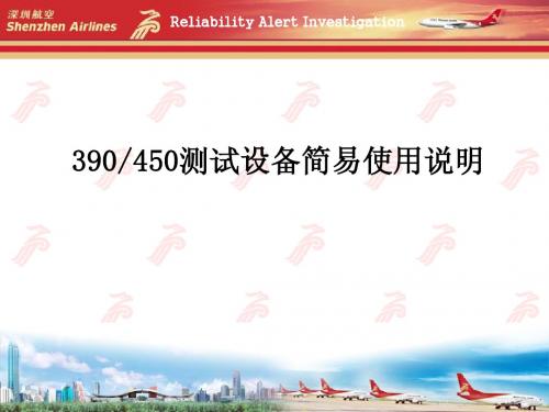
390、450测试设备简易说明
6.调节气路: 首先将CV1、CV2、V1、V2、V3、V4、V6全部关闭。 打开CV2将传感器感受引起压力调节到手册要求的压力值 (观察G3和压力表) 打开CV1将传感器上游压力调节至手册要求的压力值 (观察G1表)
打开手册要求的节流阀门(一共三个)。
Maint. & Engineering Dept.
Reliability Alert Investigation
6.温度调节 温度调节在调解面 板上左侧窗口。 按一下set健之后 数显窗口闪烁,按上下 按钮调节所需温度的上 限。(上限温度手册给 出)之后再次按下set 健。 右侧窗口红色数字 显示加热器温度,绿色 数字显示加热器限制温 度(超出此温度加热器 自动切断且发出警报)
Reliability Alert Investigation
设备使用
1.安装待测航材(390或者450传感器)。 2.连接电源、气源。 3.设备厂商说明:先供气,后加热,防止加热器过热烧毁。 4.打开气源阀门并打开CV3、CV4。 5.打开加热电源
安装待测航材
Maint. & Engineering Dept.
Maint. & Engineering Dept.
Copyright © 2007 中国深圳航空有限责任公司 维修工程部
Reliability Alert Investigation
7.观察现象,当温度调节窗红色数字达到预设值时,等待 并让设备稳定5分钟(此时温度不会再上升),5分钟过后 观察G2压力表,如果航材状态完好,则传感器放气,G2压 力表压力下降,记下压力值,并对比手册要求压降压力值。 符合标准则测试通过,测试值不在标准范围内则航材故障。 压降观察窗
Maint. & Engineering Dept.
Extech EMF450 多场景电磁场测量仪用户指南说明书
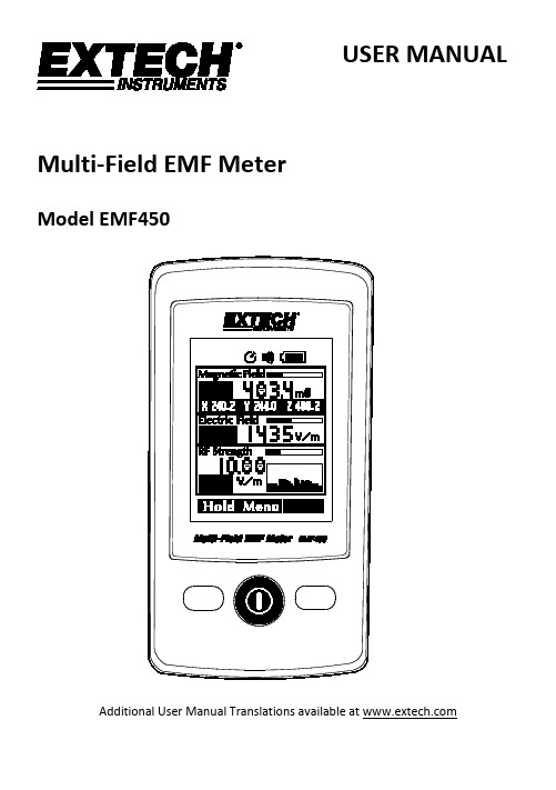
USER MANUALMulti-Field EMF MeterModel EMF450Additional User Manual Translations available at Safety InformationCAUTIONS•Before making a measurement, check if the low battery symbol is shown on the display when the meter is switched on. Replace the battery if the symbol is displayed.•In the case of prolonged storage, remove the battery from the meter to prevent damage.•Do not expose this device to direct sunlight or to extreme temperatures and humidity.•The accuracy and function of the meter may be adversely affected if the specified limits are exceeded or if the meter is handled improperly.•Clean the device with a soft, dry cloth. Moisture can damage the meter.•Electric field measurement precautions: Perform tests according to the indicated directions.WARNINGS•Use caution when working in the vicinity of powerful radiation sources.•Persons with electronic implants (e.g. cardiac pacemakers) should avoid powerful radiation sources. •Observe all relevant safety regulations.•Carefully read the operating instructions for equipment generating or conducting electromagnetic energy that will be measured.•Do not operate near combustible gases or in damp environments.•Be aware that the field strength in the near vicinity of radiators increases proportionally to the inverse cube of the distance. This means that enormous field strengths can result in the immediate vicinity of small radiation sources (e.g. leaks in waveguides or inductive ovens).•Field strength measurement devices can underrate pulsed signals, particularly with radar signals, in which case significant measurement errors can result.•All field strength measuring devices have a limited specified frequency range. Fields with spectral components outside of this frequency range are generally incorrectly evaluated and tend to beunderrated. Before using field strength measuring devices be certain that all field components to bemeasured lie in the specified frequency range of the measuring device.•For indoor use; Pollution level II•Operating altitude below 2000’ (6562’)IntroductionThis meter simultaneously measures and displays Magnetic Field, Electric Field, and RF Strength. The unit of measurement and the measurement types are expressed in units of electrical and magnetic field strength and power density. This meter is ideal for EMF measurements of power lines, electrical appliances, industrial devices, cell phones, base stations, and microwave leakage. This device is shipped fully tested and calibrated and, with proper use, will provide years of reliable service. Please visit our website () to check for the latest version of this User Guide, Product Updates, Product Registration, and Customer Support.Features•Data hold (HOLD)•Overload display “OL”.•Brightness options: low-medium-high•Selectable Auto Power off (APO) Time: 1; 3; 5; 10; 15; 30 minutes••Information screen shows software version•Languages: English, Traditional Chinese, Simplified Chinese, Japanese, Spanish •Magnetic units selection:Gauss (mG) or Tesla (μT)•Electric field strength: V/m•RF Strength Units selection: (μW/m² ~mW/m²) (μW/cm²) (m V/m ~V/m) (mA/m) (dBm).••High-frequency EMF Readings•RF Historical Records; up to 20 groups.•Low battery indication: HIGH LOWDefinitions▪Electromagnetic RadiationThis meter is used to indicate radiated electromagnetic fields wherever there is a voltage, current, electric (E) or magnetic (H) field. Examples include the electromagnetic fields from radio broadcasting, TV transmitters and power lines.▪Electric Field StrengthThis is a field vector quantity that represents the force (F) on an infinitesimal unit positive test charge (q) at a point divided by that charge. Electric field strength is expressed in units of volts per meter (V/m). Use the units of electric field strength for measurements in near-field power measurements.▪Magnetic field strength (H)This is a field vector that is equal to the magnetic flux density divided by the permeability of the medium. Magnetic field strength is expressed in units of amperes per meter (A/m).This measurement is for near-field power measurements.▪Power density (S)Power per unit area in the direction of propagation; usually expressed in units of watts per square meter (W/m2) or, for convenience, milli-watts per square centimeter (mW/cm2). ▪The characteristic of electromagnetic fieldsElectromagnetic fields propagate as waves and travel at the speed of light (c).The wavelength is proportional to the frequency.λ (wavelength) = c (speed of light)f (frequency)Near-field is assumed if the distance to the field source is less than three wavelengths. For far-fields, the distance is more than three wavelengths. In the near-field, the ratio ofelectric field strength (E) and magnetic field strength (H) is not constant, so measure each separately. In the far-field, however, it is enough to measure one field quantity, andcompute the other accordingly.Display description1. Data Hold2. Auto power off (APO)3. Audible alert4. Battery status5. Magnetic Field bargraph6. Magnetic Field digital reading7. XYZ axes values8. Electric Field bargraph9. Electrical Field digital reading 10. RF strength bargraph 11. RF strength histogram display 12. Select 13. Menu 14. Hold / Enter15. RF electronic field color alert* 16. RF strength digital reading 17. RF Strength indication area 18. LF Electrical field color alert* 19. Electrical field indication area 20. LF electromagnetic field color alert* 21. Magnetic field indication area*Color Coded Alert Table (for reference purpose only) see items 16, 19, and 21 above.Magnetic Fields Electrical FieldsRF Strength Low 0~10.00mG 0~500V/m 0~0.99mW/m 2 (0~0.59V/m) Medium10.01~100mG501~1000V/m1~9.99 m W/m 2 (0.6~1.9V/m) >1001V/m>10 m W/m 2 (>2V/m)Note: Alarm beeper sounds when readings enter the red region.Conversions1W/m² = 0.1mW/Cm² = 100μW/Cm². 1mW/m² = 0.1μW/Cm²OperationPower ON/OFF1.Press the power button to power the meter. The display will show the mainmeasurement screen. If the meter does not power on, check that the batteries areinstalled correctly and are fresh (see battery installation/replacement section later inthis guide).2.Press and hold the Power button for 3 seconds to power off the meter.Data hold (HOLD)Press the HOLD button to freeze the current readings on the display. The HOLD display icon will appear when this mode is active. To release the data press the HOLD button again.Electric Field MeasurementsThe EM450 measures the electric field (Electrical Power) in the atmosphere of the sensor’ssurroundings. The sensor orientation is printed on the back of the meter.Perform all tests according to the indicated direction of the electric field sensor.Hold the meter at the bottom and at arm’s length, as shown in Figure 3.Figure 3 – Orienting the meter for Electrical Field MeasurementsLow Frequency EMF Readings (Magnetic field)Point the front section of the meter toward the desired electromagnetic field to take ameasurement. The meter simultaneously displays the electromagnetic field readings ofindividual (XYZ) and the aggregated Magnetic field readings.The aggregated calculation equation is expressed as:Due to environment related magnetic field factors, this electromagnetic field (EMF) meter may display a reading of under 0.50mG prior to testing. This is caused by the magnetic noise in the environment, rather than meter failure.The Magnetic and Electric field will also display a bar indicator based on the measured value.Important: If the sensor is moved quickly, excessive field strength values will be displayed which do not reflect the actual field conditions. This effect is caused by electrostatic charges.Measurement considerations:1.Hold the meter at arm’s length.2.Point the front face of the meter toward the source of power.3.Hold the meter steady during the measurement.4.Make several measurements at various locations in the work place or other areas ofinterest. This is particularly important if the field conditions are unknown.5.Pay special attention to measuring the neighboring vicinity for possible radiation sources.Apart from active sources, those components connected to a source may also act asradiators.For example, the cables used in diathermy equipment may also radiate electromagneticenergy.Note that metallic objects within the field may locally concentrate or amplify the fieldfrom a distant source.RF strength meter readingsPoint the front face of the meter toward the desired RF field to take a measurement.The RF signal strength will be displayed with the units of measure set from the menu mode.The RF strength portion of the display will also show a RF strength history histogram and a bar indicator based on the measured value.Measurement considerations:1.Hold the meter at arm’s length.2.Point the front face of the meter toward the source of power.3.Hold the meter steady during the measurement.Menu Settings1.Momentarily, press the center MENU key to enter the main menu.2.Press the right SELECT key to cycle through the list.3.Press the left ENTER key to enter the selected option.e the right SELECT key to choose the desired setting.5.Press the left ENTER key to confirm the setting, the meter will exit the menu unless thereare more settings required for the given parameter (as in the SOUND setting); in which case continue using the keys in the same manner as described in this section.6.From the Main Menu screen (Figure 4), the MENU key can be used to exit the Main Menu.Figure 4 – Main Menu Option ScreenBrightness:Low, Middle, HighMagnetic unit:Gauss/mG, Tesla/µT(Used for testing Electrical power (50/60Hz))RF strength unit:µW/m²-mW/m², µW/cm², mV/m-V/m, mA/m, and dBm(Used for testing RF energy from 50MHz to 3.5GHz)Language:English, Traditional Chinese, Simplified Chinese, Japanese, SpanishPower OFF (Auto):NO (OFF), 1, 3, 5, 10, 15, 30 (minutes). Factory default is 5 minutes.Sound:Enable/Disablewhen ‘enable’ is selected, the keys/alarm sound menu will open.Keys: 3 options (1, 2, or 3) represent alternate keystroke sounds.Alarm: 3 options (1, 2, or 3) represent alternate alarm sounds.Information:Displays the software versionBattery Installation and ReplacementBattery InstallationRemove the rear battery cover and insert three (3) 1.5V AAA batteries observing correct polarity.Figure 5 Battery InstallationBattery ReplacementThe battery status icon shows low energy when the battery voltage drops below the operating level. See installation instructions above for battery insertion.Never dispose of used batteries or rechargeable batteries in household waste.As consumers, users are legally required to take used batteries to appropriatecollection sites, the retail store where the batteries were purchased, or whereverbatteries are sold.Disposal: Do not dispose of this instrument in household waste. The user isobligated to take end-of-life devices to a designated collection point for the disposalof electrical and electronic equipment.Other Battery Safety Reminderso Never dispose of batteries in a fire. Batteries may explode or leak.o Never mix battery types. Always install new batteries of the same type.SpecificationsSensor Type: LF - Magnetic FieldsRange: 20mG /200mG /2000mG, 2µT /20µT /200µTDisplay resolution: 0.02/0.1/1Frequency range: 50/60HzAccuracy: ± (15% + 100 digits)Sensor Type: LF- Electric Field SensorRange: 50V/m to 2000V/mDisplay resolution: 1V/mFrequency range: 50/60HzAccuracy: ± (7% + 50 digits)Sensor Type: RF StrengthRange: 0.02µW/m² to 554.6mW/m²0.02µW/cm² to 55.4µW/cm²36.1mV/m to 14.46V/m0.02mA/m to 38.35mA/m-51dB to 16dBmDisplay resolution: 0.02µW/m², 0.2µA/m, 0.2mV/m, 0.002µW/cm², 2dB Frequency range: 50MHz to 3.5GHzAccuracy: ± 2dB at 2.45GHzDisplay: 4 digits Triple color TFT displaySample rate: 6 secondsSensors: Triple axes (XYZ) ELF and RF and Electric field sensor Over range condition:The EM450 is equipped with three individual aerialsensors to measure EMF. Overload indication (OL)applies to all three axes (X, Y, and Z)Battery: Three (3) 1.5V alkaline batteriesBattery Life: Approx. 8 hoursAlarm: Beeps when readings are in the red display region Operating temperature and RH%: 5°C~40°C (41°F ~104°F); < 80%RHStorage temperature and RH%: -10°C to 60°C (14°F ~140°F); < 70%RHWeight: Approx. 120g (4.2 oz.)Dimensions: 115 x 60 x 21mm (4.5 x 2.4 x 0.08”)Copyright © 2015-2017 FLIR Systems, Inc.All rights reserved including the right of reproduction in whole or in part in any form。
HAYWARD RG450 说明书

The ReGenX model RG450 is a high performance swimming pool filter with a maximum flow rating of 2,700 gallons (10.2 KL) per hour. Manufactured from Hayward’s exclusive PermaGlassXL™material, ReGenX is designed to provide years of trouble-free operation.FEATURESPatent pending sunburst grid design ensures a balanced flow of water through your filter.Exclusive piston action regeneration instantly purges the grids of dirt and debris—extending the cleaning cycle of the filter.New glass reinforced, non-corrosive PermaGlassXL™ filter tank will provide years of trouble-free operation.Easy-Lok™ring design allows quick access to all internal components.Unique safety latch prevents unwanted entry into the tank.Self-venting design automatically purges any air present in the system.PUMP SELECTIONTo power your ReGenX filter, select acontinuous duty pump designed forabove-ground pools, such as thePower-Flo™ LX. As a general guide,choose a pump with an average outputrating of at least 40-50 gallons (151-189Liters) per minute. A flow controller isfurnished with each unit to ensure ahydraulic balance which maximizesperformance of the filter system.FILTER LOCATIONThough the filter is designed for outdoor use, it is advisable to protect electrical components from the weather. Select a well-drained area, one that will not flood when it rains.For best pump performance, locate the system below the swimming pool water line. If the system must be located above the pool water line, it can be raised as high as 2 feet (0.61 m) above the pool water line. (NOTE: PRIMING WILL TAKE LONGER AS PUMP IS RAISED HIGHER ABOVE WATER LEVEL.)Set the filter and pump on firm, level ground. Position the tank for easy access to the internals, pressure gauge and piston knob, with at least 24” (61 cm) of top clearance in order to regenerate properly. Position the filter so that it may drain by gravity.PLUMBINGUse 1-1/4” or 1-1/2” I.D. flexible plastic pipe, or hose, joined with insert fittings and stainless steel clamps. If rigid PVC is used, be sure to provide unions for easy servicing.All plumbing connections on the RG450 filter are 1-1/2” N.P.T. When making connections, use plastic male-end adapters. Apply three turns of Teflon tape or plastic pipe sealant to the male threads. Screw the fitting into the threads hand tight; then, using wrench, tighten one more full turn if necessary. Adapters have varying tolerances and overtightening with a wrench may only cause damage to the filter. Refer to the diagrams for suggested valving. Ball-type valves are recommended where needed.Securely hand tighten the union nut between the filter and pump. Connect the pool suction plumbing between the skimmer, pool outlet, and pump.Connect the pool return (inlet) plumbing.A filter drain valve or plug is furnished with each filter and is all that is needed for complete filter draining. A manual air vent valve is furnished to aid in the bleeding of unwanted air when starting or draining the filter.All electrical connections should be made in accordance with local codes.Refer to pump instruction book for pump information.••••••1. 2. 3.3.4.5.6.7.8.9.NOTE: ANSI/NSPI-4 Article V, standard for above-ground and on-ground pools, advises that components such as the filtration system, pumps and heater be positioned so as to prevent their being used as a means of access to the pool by young children.1.*Not furnished with filter.2.ISRG450-98MODEL RG450 SERIES**MODEL RG450P A R T SS E R I E S F I L T E RBEFORE STARTING THE FILTERObtain a supply of operating chemicals, D.E. (or cellulose based substitute), and a pool test kit. Use only the swimming pool grades of D.E. Consult your local dealer for further information and brand choices. In recent years, wood based cellulose products have been used as an alternative filter media to D.E.Superchlorinate the pool water by adding unstabilized granular or liquid chlorine. Stabilized forms of chlorine are recommended for normal use after the initial clean-up of the water. Follow chemical manufacturer’s recommendations for superchlorination and daily use.STARTING THE FILTERBe sure filter drain plug is closed. Open manual air vent valve a few turns and open suction and return valves (when used). Caution: All suction and discharge valves must be open before operating the filter system. Failure to do so could cause severe personal injury and/or property damage. Be sure the ReGenX Easy-Lok™ lid is secure and locked.Prime and start the pump following the manufacturer’s instructions. Air trapped in the system will automatically vent to the pool. When there is a steady flow of water back to the pool, the filter is ready for precoating.Be sure to close the manual vent valve. DO NOT operate the filter for more than one minute without the precoat charge.PRECOATINGScoop 2 lbs. (0.91 kgs) diatomite into the system through the skimmer as fast as the plumbing will take it. Note and record the pressure gauge reading after the diatomaceous earth has been added. This is the “pre-coat pressure.” If using a cellulose filter media use approximately 1-1/4Hayward scoops (5/8 lbs. or 0.28 kgs). For more detailed information,consult the manufacturer’s recommendations. Note and record the pressure gauge reading after the cellulose filter media has been added.This is the “precoat pressure.”FILTERINGFiltration starts as soon as the filter has been precoated. As the filter removes the dirt and debris from the pool, the accumulated dirt causes a resistance to flow. As a result, the gauge pressure will rise and the flow will decrease. When the pressure rises 7-10 PSI (.49-.70 Bar) above the precoat pressure, regenerate the filter.REGENERATION (EXTENDING THE CLEANING CYCLE)Stop the pump. Unlock the piston knob. Move the piston up and down rapidly 6-10 times. When finished, lock the piston knob back in the lower position. Restart the pump and filtration will resume at or near the original flow pressure. You have just “regenerized” your D.E. and extended the cleaning cycle of your filter without backwashing, draining, or cleaning, saving your chemically-treated water, D.E. and time.After each regeneration, and until the filter is cleaned, there may be a slight increase in the starting pressure. This is the result of dirt accumulating within the filter and is completely normal.CLEANING/REMOVING GRID ELEMENTRecommended when the gauge pressure rises more than 10 PSI (0.70Bar) in less than a 24 hour period.Shut off the pump.If filter is located below water level, close valves or block off discharge line to prevent back flow of water from the pool that may end up on your feet or unnecessarily lower your pool water level!Unlock the piston knob and repeat regeneration process as described in REGENERATION.Open the filter drain and the vent valve located at the top of the filter. This will accelerate the draining process.Allow water and dirt to empty completely.The filter should not have any water in it. Depress safety latch,unscrew and remove Easy-Lok lid (counterclockwise direction).Carefully lift off lid and piston assembly, straight up, to gain access to the grid element.Lift out grid element and clean as in the PREVENTATIVE MAINTENANCE section below.PREVENTATIVE MAINTENANCEPressure wash cartridge inside and out with Hayward’s Jet-Action Cleaning Wand (EC2024) or a garden hose.Allow to dry and brush pleated surface areas.To remove algae, suntan oil and body oils, soak for one hour in a solution of filter element cleaner.(See your local pool dealer).To remove calcium or mineral deposits, soak in muriatic acid solution.*Caution: use a plastic container and take extreme care—harmful to eyes, skin and clothing.After cleaning, flush with water.REINSTALLING GRID ELEMENTClean any collected debris from the bottom of the filter body.Carefully replace gridelement into the filter body ensuring that the element is even on the collector hub in the bottom of the filter body.Place Easy-Lok lid so it is level on filter body,locating the notch under the lock-ring directly overthe drain (See Fig. 1). Then turn clockwise until it engages and is secured by the safety latch.Proceed as in STARTING THE FILTER and PRECOATING.1.2.1.2.3.4.5.6.7.8.1.2.3.4.1.2.3.4.CAUTION: Use a plastic container and take extreme care when handling cleaning agents as they can be harmful to eyes, skin and clothing. After cleaning, flush with water.Muriatic AcidWaterSolutionHawyard grid elements are specially designed and engineered for use in ReGenX filters. For best results, use only genuine Hayward elements in your filter. The Hayward name is your guarantee of quality. VACUUMINGVacuuming can be performed directly into the filter whenever needed. For fastest results, regenerate the filter before and after each vacuuming period. For heavy spring clean-ups, we recommended using a Hayward SP0727 diverter valve to bypass the filter and accelerate the clean-up process. Consult your local Hayward dealer for a detailed explanation. WINTERIZINGIn areas where sub-freezing temperatures can be expected, the filter should be drained and/or removed from its operating location and stored indoors. Clean the grid element at the end of the pool season by using your garden hose with a high pressure nozzle or the Hayward EC2024 Jet-Action™ Cleaning Wand. You will then be prepared to enjoy your pool the next spring.SERVICE AND REPAIRSConsult your local authorized Hayward dealer or service center. No returns may be made directly to the factory without the expressed written authorization of Hayward Pool Products, Inc.ALGAE CONTROLAlgae is a form of plant life which can vary in size from a few thousandths of an inch to the size of a small tree. Of the many forms of algae, those most frequently found in swimming pool water are microscopic in size and green in color.Algae readily grows in sunlight and can, under favorable conditions, quickly overgrow a swimming pool turning it completely green in just a few hours. On the other hand, swimming pool water can be kept unfavorable to algae growth simply by maintaining a chlorine level of at least 1.0 ppm in the water at all times. The chlorine level should be checked at least once a day using a suitable test kit.If an algae condition develops and the pool water “blooms” green, superchlorination of the pool will be necessary to clear it. Add unstabilized granular chlorine, or liquid chlorine. Follow chemical manufacturer’s recommendation for superchlorination. The algae will quickly become inactive and can then be removed by the filter. Live algae on the other hand, multiplies so fast that the filter cannot keep up with its growth rate. In an active algae situation, it may be necessary to regenerate the ReGenX filter as frequently as every 2 to 3 hours. When correctly used, commercial algaecides are effective against algae, though algaecides should be used in conjunction with, and not as a substitute for regular chlorination or superchlorination.Maintaining a chlorine level of at least 1.0 ppm in the pool water at all times is the most effective way to prevent algae growth in swimming pools.POOL CHEMISTRY GUIDELINESACTION REQUIRED TO CORRECT POOL CHEMISTRYTO RAISE TO LOWER SUGGESTED POOL CHEMISTRY LEVELSpHTOTAL ALKALINITY CHLORINE (UNSTABILIZED) CHLORINE (STABILIZED) CHLORINE STABILIZER (Cyanuric Acid)7.2 to 7.6100 to 130 ppm0.3 to 1.0 ppm1.0 to 3.0 ppm40 to 70 ppmAdd Soda AshAdd Sodium BicarbonateAdd Chlorine ChemicalAdd Chlorine ChemicalAdd StabilizerAdd Muriatic Acid or Sodium BisulphateAdd Muriatic AcidNo action - chlorine will naturally dissipateNo action - chlorine will naturally dissipateDilution - partially drain & refill pool with waterthat has not been treated with Cyanuric Acid.©1998 Hayward Printed in U.S.A.Rev. 12/98。
450电直的组装与调试

450电直的组装与调试本贴内容主要为450电动直升机新手准备的,450电直作为一个机电复合系统,本身虽然不是特别复杂,但新手——特别是单打独斗的新手仍然存在一些技术障碍、一些朋友虽然大体了解如何做,但也有许多不太确定的地方。
玩航模除了让我们体验到飞翔的乐趣之外,让一堆零件在我们手中变成一个充满机械美感的作品也是一种非常愉悦的事情。
一部450电直装到能飞起来的层次,大体分几个部分:1.机械部分安装、2.电子部分的安装、3.机电综合调试。
这个帖子先从机械部分安装说起。
(本贴以非耐克斯的fire为例,其他机型可以参照一下)工欲善其事,必先利其器,首先我们准备好如下工具,图中由左向右分别为小十字螺丝刀、大十字螺丝刀、1.5、2.0、2.5内六角螺丝刀、5mm小套筒、尖嘴钳、镊子、游标卡尺(普通尺具也可以)、剪刀、螺距规,这些工具有些是机械部分安装必须的,有些是调机用的,本帖没有把它们分开。
是后续过程使用了,本贴没有把它们分开。
时需要小心日字框内的调整间隙的垫片不要弄丢了。
将平衡翼片旋入平衡杆,为了保证平衡和飞行安全,应把平衡翼杆的螺纹全部旋入平衡翼片内,两片平衡翼旋入的长度要一致。
使用游标卡尺量取两侧平衡翼杆的长度,并精细调节到两端一致。
调整好长度后,稍微顶上日字框上的顶丝,从侧面观察平衡翼片并调整平衡翼片与日字框平行(使平衡翼0攻角)。
调整完毕,顶丝上涂少许螺丝胶并锁紧(为了固定已经调整好的平衡翼,两个顶丝应分别锁紧、不要同时松下来。
当然,由于螺丝胶的固化需要一段时间,也可以先在顶丝上涂螺丝胶,然后做上一步的调整工作,调整完毕后直接锁紧就行了)。
这里要特别提醒两件事情:一、全机所有紧固到金属部件的螺丝(包括金属螺丝帽)都要上螺丝胶,同时注意所使用螺丝胶的强度和用量,螺丝胶太强或者用量太多,可能会给日后的维护工作带来麻烦,(装到非金属材质上的螺丝无需上胶,它们一般具有自锁性)二、450级别的电直所用的螺丝都很小,在紧固时一定注意力度,否则很容易出现滑丝和内六角被拧圆的问题。
Yamaha 450e 链带刹车与刹车挡盖套件说明书

SPARE PARTS LISTCHAIN SAWS450e IIRef Part No Description Remark QTY KIT 15442172-01CLUTCH COVER ASSY1 25045428-01COVER LID11 35370430-01BRAKE BAND ASSY11 45440830-01WEAR PROTECTION11 55038552-01GUIDE BUSHING11 65034659-01BRAKE SPRING11 75440829-01COVER LID11 85038908-02KNEE JOINT ASSY11 95038929-01PIN11 107353108-20E-CLIP11 115373929-01SCREW11 125373472-01GEAR ASSY11 135373926-01HEAT PROTECTOR11 145443575-01LABEL11 155262218-01SCREW CITXPANT101 165253543-01BEARING SLEEVE11 175442505-01WEAR PLATE11 185373478-01KNOB1Ref Part No Description Remark QTY KIT 15440979-01CLUTCH COVER ASSY1 27353108-20E-CLIP11 35372866-01PAWL11 45400633-01CHAIN GUIDE11 55370174-01BEARING SLEEVE11 65038908-02KNEE JOINT ASSY11 75034659-01BRAKE SPRING11 85038552-01GUIDE BUSHING11 95440829-01COVER LID11 105262218-01SCREW CITXPANT71 115440830-01WEAR PROTECTION11 125370430-01BRAKE BAND ASSY11 135038929-01PIN11 145373970-01WORM SCREW11 155370794-02WORM WHEEL11 167404807-02O-RING11 175032300-63WASHER11 185443768-01LABEL11 195032200-01HEXAGON NUT1Ref Part No Description Remark QTY KIT 15371105-03CLUTCH ASSY1 25373591-01CLUTCH SPRING21 35780979-01CLUTCH DRUM ASSY1 45032552-01NEEDLE BEARING13 55039318-01PUMP PINION1 65400579-01PUMP PISTON1 75371548-01PUMP CYLINDER1 85440842-02OIL HOSE1Ref Part No Description Remark QTY KIT 15815306-01CYLINDER COVER SYSTEM1 25227360-01LABEL11 35038947-01SNAP LOCKING3STARTER450e IISTARTER450e II Ref Part No Description Remark QTY KIT 15794253-11STARTER ASSY125054228-02STARTER HOUSING11 35372832-01SLEEVE11,2 45400575-02SPRING CASSETTE ASSY11 55032128-10SCREW CCRPANT21 95032177-16SCREW IHSCT11 105038589-01STARTER ROPE11 115372325-01STARTER HANDLE11 125032173-21SCREW41 135440815-01COOLING AIR CONDUCTER1 145808153-02LABEL1 155866595-03STARTER PULLEY11Ref Part No Description Remark QTY KIT 15802796-01FLYWHEEL ASSY1 25372456-01STARTER PAWL21 35018199-03SCREW21 45032300-42WASHER21 55292711-01SPRING21 65032204-01NUT1 75796388-05IGNITION MODULE1 85101015-01WIRING ASSY1 95032002-20SCREW IHSCFM2Ref Part No Description Remark QTY KIT 15441477-02MUFFLER ASSY1 25797533-01SCREEN11 35797532-01HEAT DEFLECTOR1 45797531-01GASKET17 57255368-55SCREW IHSCM2 67241287-59SCREW CRPANM11 75449720-01GASKET KIT Set of Gaskets1Ref Part No Description Remark QTY KIT 15440823-01PIPE ASSY1 25032002-16SCREW IHSCFM4 35440838-01INTERMEDATE WALL1 45440840-01FLANGE1 55032107-25SCREW IHSCFT2 65440841-01FLANGE1 75441482-01THROTTLE1 85064504-01CARBURETTOR C1M-EL37B1 95055147-01FILTER HOLDER ASSY1 105442314-01SHACKLE19 115039366-01PURGE air purge1 125444019-01HOSE suction hose1 135775351-01RETURN HOSE return hose1 145443599-02CONTROL1 155032107-50SCREW IHSCFT2 165440808-01AIR FILTER80µ1 165440808-02AIR FILTER44µ1 165440808-03AIR FILTER Felt1 175020810-01SHAFT ASSY17 185020811-01SPRING17 195020808-01COLLAR17 205020812-01VALVE17 215034818-01SCREW17 225373852-01CLIP17 235020809-01ROD17 247355830-00WASHER114Ref Part No Description Remark QTY KIT 15441198-03CYLINDER1 25440889-05PISTON ASSY11 35440887-01PISTON RING11,2 45442113-01CIRCLIP11,2 55032563-02NEEDLE BEARING11 65441087-01GASKET111 75441092-01GASKET111 85032005-27SCREW IHSCM4 95032351-11SPARK PLUG1 105400573-01SUPPORT1 115449720-01GASKET KIT Set of Gaskets1CRANKSHAFT450e IICRANKSHAFT450e II Ref Part No Description Remark QTY KIT 15256050-01CRANKSHAFT ASSY125440620-01BEARING21 35440138-01SEALING21 45032563-02NEEDLE BEARING1Ref Part No Description Remark QTY KIT 15374382-01CRANKCASE1 25038758-02STIFFENING PLATE11 35038754-02BAR BOLT11 45373346-01BAR BOLT11 55440364-01BAR BOLT11 65032409-05NEEDLE ROLLER11 75300261-19CHECK VALVE11 85374035-01FILTER11 95440833-01OIL SCREEN11 105443316-01GUIDE PIN31 115038693-01SUPPORT2 125226200-03TANK CAP ASSY1 135892411-01GASKET112 145035789-01HOLDER112 155038863-01PIN1 165032188-76SCREW IHSCT2 175010076-01SUPPORT2 185032151-03SCREW IHSCT1 195440940-01CHAIN GUIDE PLATE1 205032170-10SCREW CCRPANT1 215039059-01SPIKE1 225032175-20SCREW IHSCFT2 235054227-01HAND GUARD1 245038924-01LOCK1 255038930-01SCREW2 265034365-01POSITION SPRING1Ref Part No Description Remark QTY KIT 15258621-04FUEL TANK ASSY1 25032128-10SCREW CCRPANT1 37201825-20PARALLEL PIN1 45440997-01THROTTLE TRIGGER1 55440999-01SPRING1 65440998-01THROTTLE LOCKOUT1 75041222-01HANDLE INSERT1 85040988-01THROTTLE CABLE ASSY1 95441286-01FUEL HOSE1 105034432-01FUEL FILTER1 115775351-01RETURN HOSE1 125226200-03TANK CAP ASSY1 135892411-01GASKET112 145035789-01HOLDER112 155443750-01LABEL1 165010076-01SUPPORT1 175441012-01ANTIVIBRATION ELEMENT21 187211263-39GROOVED PIN11 195011529-01TANK VENT ASSY11Ref Part No Description Remark QTY KIT 15440839-01FRONT HANDLE1 25032188-76SCREW IHSCT3 35032102-70SCREW IHSCT2 45038983-01ANTIVIBRATION ELEMENT1Ref Part No Description Remark QTY KIT 15064504-01CARBURETTOR1 25020782-01COLLAR11 35020783-01COLLAR11 45020784-01SCREW11 55020786-01SPRING11 65020787-01SPRING11 75034790-01SCREW11 85034796-01SCREW11 95034797-01VALVE11 105034800-01PIN RETAINING SCREW11 115034801-01SCREW11 125034805-01SCREW41 135034811-01PIECE11 145034818-01SCREW21 155035356-01PLUG WELCH21 165035357-01STRAINER11 175036659-01LEVER11 185370201-01GASKET11,37 195373831-01DIAPHRAGM PUMP11,37 205020789-01COVER11 215373833-01SCREW11 225373834-01SPRING11 235373837-01COVER11 245442377-01NOZZLE ASSY11 255020790-01DIAPHRAGM11,37 265020791-01LEVER11 275051017-01LEVER11 285020794-01SHAFT ASSY11 295020795-01SHAFT ASSY11 305022477-01VALVE11 315020798-01COLLAR11 325373836-01GASKET11,37 335020817-01LEVER11 345020799-01SCREW11 355020800-01SCREW11 365020801-01VALVE11 375020802-01GASKET KIT B=Set of Gaskets1 385441195-01PLUG11ACCESSORIES450e IIACCESSORIES450e II Ref Part No Description Remark QTY KIT 15016917-01COMBINATION WRENCH1Ref Part No Description Remark QTY KIT 15444645-01WINTER KIT Winter kit1 25032170-16SCREW CCRPANT21Illustrated Parts List - IPL UpdateProduct Name(s)Description of changeComment1. Oil hoseNew version Old version544 08 42-02544 08 42-01Page 1 of 1These changes are fully exchangeable.1. Updated Oil Hose 544 08 42-02 added. Sealing knob removed to simplify assembly.2. Number change due to a durability update on Ignition Module to 579 63 88-05.H450e II2. Ignition ModuleNew version Old versionMarking:Marking:579 63 88-05 579 63 88-03。
猎鹰450说明书

34
35 35 36 37 38 39 40 42 43 43 44 46 48
食 普通飞行模式示意固 食 3D模式下的制飞模式示 意 固 食 安韭示 意 回 食 飞机童装完成示意 圄 食 主旋翼平衡与双桨商直校E 食 动力异常检查 食- 锻保养方法
食 iI!!臭配件示意固
食 配件列表
'喜〉应主剖停止究电
翩翩翩咂肝凹的时源
8 . i:衡 勿拆开平.冤叫且量及附件 . ' 当电池还有很俗'香请勿急于充电
A
但电池使用注意事项
.M止侨卸殴.组电池 1
E
2 彼此短篇电池 1
,.比如源旁使用 1
也 .tt精咆池技人.. '然业将钉子插入电池中
,.让冲击就搜纳 1
溜,你 中戴勇温 1 用铁镶敲打就网"跟 1
通搜飞饥撮但锁巧在掌写初期有"定的艰度
要尽量遮兔擅自
爆作飞行
'在经碰的入士在费捕'才可以"但飞行
m练习咆'自锁椒'是入 n. 像温. ,
x
J\
更民
e 远离运"中军件
当离开饥主.翼与庵篇翼逞'售网切勿触?晨,车运离旧睛'忡的郎 ,拿
坏
元,略是人的头都要离开主 幅画在蜒的簸,李面
以避免造成危险及组
x阕
&l 千
凰"
下
k
-4 且'镜
L' 最 bM
t
i
副
友
副
偏 宿
费
捕'
右 能 向
-
h
· 协
!
n凰'"吁美
YAESUFT450说明书
YAESU FT-450功能与操作一、开机与关机开机和关机都是按压ON/OFF钮1秒。
二、接收信号开机后,旋转DSP/SEL按钮,这是一个三向钮(左、右和下压)。
举例:接收13.107USB,下压一下,看到最前面三位数闪动,用三向钮旋到13.1再按压三向钮一下,再旋末尾两位数到10(由于步进的关系不能直接转到07的),这时就要用大旋钮(细调)调到07的位置。
按带上下箭头的MODE模式钮,调到USB模式。
收到信号了,如需要调整DSP(数字信号处理),按一下DSP钮,屏幕上出现箭头,每按压一下DSP钮,箭头滚动,此时再用DSL/SEL钮(运用该键的三向)逐项调整到最顺耳的听感。
三、本机DSP数字信号处理的含义CONTOUR 周期、等高线。
NOTCH 陷波滤波器。
DNR 动态降噪。
WIDTH 带宽。
—SHIFT+调整DSP总体的中心通频率响应特性等级。
AM SSB FM…..模式不同,以上的条目也会有所不同。
(LSB下边带USB 上边带,SSB是单边带的总称,)四、右上角的接收模块剖图从左到右ANT天线入,ATT-IPO-R.FLT-NB-AGC 一步步的模块信号处理流程,ATT信号衰减、IPO射频前置放大器、NB 杂讯消除器、AGC自动增益控制。
对应ATT/IPO钮、NB钮进行开关,ON为开,OFF为关;R.FLT修平滤波器总是为开状态。
AGC钮可设置快(FAST)慢SLOW,也可以自动(AUTO)选择。
五、大旋钮及旁边的按钮大旋钮起细调之作用,只有在SSB模式下可调,AM和FM模式下不能调。
配合波段BAND上下按钮作粗选,大旋钮作细调,按下快键FAST,大旋钮的速度增大一倍。
调准后可按下LOCK锁定频率。
VFO变频器提供了A和B两个频率,只要按A/B键就可以互相切换了,A=B那个按钮,是令VFO-B的频率与VFO-A一样,相反A与B一致也成立,这些钮主要是为了使用上的方便快捷。
KEYER是电键的按钮;CLAR为精调按钮,按下,屏幕显示0,00,旋大旋钮起作用,它提供了上下9.9k的精调,再次按下,回复原来的频点。
FEKO入门操作练习

FEKO培训系列教程培系列教程FEKO 入门EMSS CHINAThe FEKO program model总揽•CADFEKO GUI 完成模型的全部建模及设置•主要功能:–定义变量–参数几何定义–面网格及体网格剖分–输入/输出接口Parasolid, dxf,stl, other CADFEKO *.cfxfiles and *.fek files etc.模型检查及后处理•POSTFEKO 用于后处理•主要功能:–分类式用户界面–2D、3D 结果显示e–可同时显示多模型–自动更新结果FEKO计算流程•CADFEKO中建立新模型.•CADFEKO 生成CFX 文件.•网格剖分完成后, CADFEKO 生成CFM 和PRE 文件.•PRE 文件仅需高级控制时修改(使用EDITFEKO)•CFM 文件保存有网格信息用于求解.•FEK 文件在求解时生成•需要修改模型及求解设置在CADFEKO中更改RUNFEKOPRE FileCFM FileCFX FileFEK FileFEKO 计算流程续.1.使用CADFEKO建立模型,网格剖分以及求解设置.2.FEKO 求解运行.33.查看输出及警告/错误等.4.在CADFEKO 中修改并恢复计算•Note: 模型可以在POSTFEKO中检查OUT FileFEK FileBOF File RUNFEKOFEKO 计算流程续.•FEKO的计算结果文件储存在BOF 和OUT 文件中.•OUT 文件是文本文件,存有详.细求解信息.•POSTFEKO 读取二进制BOF 文件显示计算结果.OUT FileBOF FilePOSTFEKOFEKO各模块总结建模检查模型运行FEKO求解POSTFEKO绘制结果The FEKO program modelA demonstration of FEKO in actionFEKO 使用演示: 平面螺旋天线•学习FEKO工作流程•从演示中学习–FEKO工作流程•演示中一些概念,在后面培训中会详细介绍问题描述•距离尺寸的单位:cm•螺旋线的特性:–Growth ratio : 1.1459–Ground plane : 35x35Ground plane:35x35–Begin radius: 1–End radius: 22.5–Slot width: 1.8–馈电位于中间,两个螺旋比中间–电流分布–300 MHz使用CADFEKOHow to zoom, translate, rotate and snap in CADFEKO在CADFEKO中:缩放, 移动, 旋转,捕获关键点•点击创建立方体cuboid,点击Create and Close•缩放: 鼠标中间滚动•视图移动: 点钟CTRL,并摁住鼠标左键,移动鼠标左键移动鼠标•旋转: 选中鼠标左键,移动鼠标•捕获关键点:•大概网格视图移动鼠标,左键选择捕获点案例1金属六面体散射问题说明•互动练习•演示FEKO使用规则•RCS 散射分析频率:300 MHz•300MHz•右边是期望的计算结果创建立方体1.打开CADFEKO2.点击菜单Geometry→Solid→Cuboid, 或者选择几何模型创建按钮3.输入base corner 坐标(-0.25,-0.05,-0.5)4.输入Width as 0.55.输入Depth as 0.16.输入Height as 1求解参数设置[1]1.设置frequency –在树管理中右键“Frequency”2.输入300e63.设置激励“Excitations”4.如右图所示Preview of step 4求解参数设置[2]1.设置远场:“Calculation” 并选择“Request far fields”–选择在入射方向计算远场–Click create and close创建网格1.点击Mesh→Create mesh2.设置edge length to 0.1(约λ/10)3.点击Create4.4右键Cuboid1Mesh→Info可以查看网格统计•可以选择关闭几何视图,以便更好显示网格视图计算求解1.保存工程为cuboid12.选择Run→FEKO.•在新窗口中显示出计算信息•程序先自动运行PREFEKO 生成.fek文件•接下来FEKO solver 运行(automatically)•PREFEKO can also be run separately byselecting Run→PREFEKO (to view modelin POSTFEKO)查看结果1.选中运行Run→POSTFEKO *2.在Home tab 中选择Cartesian创建2D笛卡尔图3.在Home tab 中选择Far field,在下拉菜单中选择FarField14.在右侧结果中选择点击dB修改曲线1.在Display tab 中:–点击Legend并选择None–点击Chart text, uncheck Auto 并输入title:“RCS of Cube”2.在Display tab 中点击Axis Settingsand do the following:–Go to the Vertical tab–Uncheck all 3 check boxes–Change the Minimum value to -43.在Trace tab 中:–首先确认曲线被选中–修改颜色Line colour为红色–修改Marker Style 为实线–修改Marker colour为红色修改曲线1.在Format tab 中:–点击图片title–修改字体为18–同样修改纵坐标和横坐标•修改颜色等信息介质体RCS分析增加电复杂性问题说明•基于第一个例子•设置立方体为介质材料•观察曲线变化设置介质区域1.关掉POSTFEKO2.In CADFEKO Choose File→Saveas cuboid_diel3.显示几何,隐藏网格4.在管理树种点击Media•也可双击Media:wood–Label: wood7.选择cuboid1设置介质区域1.选中cuboid ,打开regions,菜单2.右键properties3.设置该区域为‘wood’.•这个区域的颜色将改变4.重新mesh,覆盖以前的网格运行FEKO并对比结果1.运行FEKO2.创建远场结果图3.曲线设置为dB, range -40 to 10 dB4.在Home tab Add model4tab点击Add model–导入*.fek file5.选择–点击FarField,部分重叠的立方体增加几何结构复杂度问题说明•在案例2中,增加新的立方体•第二个立方体同样大小,但是位置改变,使得与第一个部分重叠•立方体2的材料不同•计算新的RCS创建立方体21.不用关闭POSTFEKO,直接返回CADFEKO2.选择cuboid1 删除网格,3.创建新立方体:base corner:(-0.05,0,0)with dimensions W=0.1, D=0.5,H=14. 剖分网格:edge length = 0.1•显示网格•错误网格修改重叠部分1.删除所有网格2.选择被减掉的立方体2,点击–选择Cuboid1 点击OK View ofcompleted step 2 3.在几何树中,点击Cuboid2,点击右键选择Copy及copiedUnionView ofcompleted step 4查看结果1.设置所有的区域为‘wood’2.创建网格3.运行FEKO,不覆盖前次结果回到4.返回到POSTFEKO金属体前的偶极子天线问题说明•在前面例子中增加偶极子天线•激励源从平面波,改为线电压源•结构查看从RCS,变化为方向图•立方体材料为金属添加偶极子天线1.将工程修改为cuboids_and_dipole2.将立方体区域设置为free space2f•Note: 立方体表面仍为金属3.创建线. 坐标为:1.(0.5,0.5,-0.25)2.(0.5,0.5,0.25)设置端口和激励1.选择创建port Create port →Wire port–点击3D视图中的线–选择Middle and Create•Port1 将出现在管理树中3.删除PlaneWave 激励4.右键Excitations ,选择Voltage Sourceand Create设置频率及远场计算1.设置频率22.设置要计算的远场:–Calculate fields as specified–Enter the field values as shown–OK•在试图中一个示意图出现剖分网格1.点击mesh → Create mesh–点击Wire segment length clickSuggest.–在Wire segment radius 输入0.0010001•在Ports 管理树中,将出现port的网格图标•查看网格节点:2.保存3.运行FEKO求解查看结果1.运行POSTFEKO•查看结果。
Bryton Rider 450 手冊说明书
使用手冊目錄開始使用 (4)Rider 450 介紹 ............................ 4配件 ................................................ 5狀態圖示 ........................................ 5步驟 1: 充電您的 Rider 450 ....... 6步驟 2: 打開 Rider 450 .............. 6步驟 3: 初次設定 ........................... 6步驟 4: 接受衛星訊號 ................... 7步驟 5: 使用 Rider 450 開始您的騎乘 .................................................7重新啟動 Rider 450 .................... 7分享您的運動紀錄 ........................ 8自動上傳紀錄至Bryton Active Appp ................... 9與Bryton Active App資料同步...................................... 10下載 Bryton Update Tool . (12)檢視歷史紀錄 (15)訓練 (13)訓練計劃...................................... 13訓練課程...................................... 14Bryton測試 (14)設定 (20)碼錶資訊 ..................................... 20智慧計圈 ..................................... 22設定運動提醒 ............................. 23智慧暫停 ..................................... 23資料記錄 . (24)GPS 系統選擇 ............................ 25變更系統設定.............................. 26藍牙 ............................................. 29自動切換 ..................................... 30啟動存檔管理 ............................ 30紀錄提示 ..................................... 31檢視記憶體容量 ......................... 31回到出廠模式 ............................ 32檢視韌體版本 ............................. 32ANT+ / BLE 周邊設備 .............. 33高度 ............................................. 35個人化使用者資訊 ..................... 36個人化單車資訊 ......................... 37無線網路 . (39)Bryton Active App進階設定 (40)碼錶資訊 .................................... 40高度校正 ..................................... 41智慧通知 . (42)附錄 (43)規格 ............................................ 43電池資訊 ..................................... 44安裝 Rider 450 ......................... 46安裝 速度/踏頻/ 2合1踏頻器(選配) .......................................... 47安裝「心跳帶」(選配) ............. 48輪徑尺寸及圓周.......................... 49Rider 450 基本維護.................. 50Rider 450 螢幕起霧排除.......... 50螢幕顯示用語說明 (51)檢視運動/訓練紀錄 (15)路線導航 (18)警告開始進行或修改任何訓練計畫前,請務必諮詢醫師。
WJQ450系列光纤直放站培训资料(V2[1].0)
![WJQ450系列光纤直放站培训资料(V2[1].0)](https://img.taocdn.com/s3/m/d4e2602a31126edb6e1a1007.png)
2.1近端机
2.1.1近端机主设备及安装配件:一套
2.1.2近端机AC220V交流电源线一条或DC-48V电源线一条
2.1.3远供电源:一套(可选项)
2.1.4定向耦合器:一个
2.1.5光分路器:一副(可选项)
2.1.6尾纤和射频电缆:根据实际工程配置数量和长度
2.1.7电话MODEM:一个(可选项)
型号
WJQ450/GJ近端机
WJQ450/GY远端机
备注
频率范围
异频
上行:457~459MHz;下行:467~469MHz
同频
上行:457~459MHz;下行:457~459MHz
光路参数
光波长
1.31μm/1.55μm
发射光功率
≥0dBm
光纤
G652单模光纤
光纤连接器
FC/PC
光接收灵敏度
≤-18dBm
下行
(-)23dBm
0光衰时
输出功率
上行
≥-10dBm(耦合型)
……
下行
……
37dBm
在27~37dBm连续可调
互调衰减与杂散发射
≤-36dBm/9KHz~1GHz
≤-30dBm/1~12.75GHz
三阶互调
≤-50dBc@-10dBm
≤-40dBc@37dBm
其他电气指标
驻波比
≤1.4
通道打开时延
1.1光收发模块
光收发模块分为光发和光收两部分,其中光发部分是实现电光转换,将RF信号调制在光信号上;而光收部分是实现光电转换,将原来的RF信号从光信号上解调出来并经过一定处理。该模块可分为单纤传输(工作光波长为1.31μm和1.55μm)和双纤传输两种(工作光波长为1.31μm)。它具有宽工作频带、低底噪、高光输出功率以及射频线性度高等特点。另外,模块带有射频增益控制,便于工程的实际开通。
A4400交换机用户操作培训资料

ALCATELA4400用户操作及培训资料目录目录1. 4400交换机机架简介 (3)2. 4400交换机功能板简介 (4)3. 4400交换机系统命令 (6)4. 开关机方法及注意事项 (7)5. 4400交换机系统数据管理 (8)6. mgr 管理工具 (9)7. 分机管理 (10)8. 组管理 (13)9. 中继管理 (15)10. 号码编译 (20)11. 类别管理 (23)1.4400交换机机架简介左图为4400机架ACT 是用于插交换机功能板的分架。
ACT编号从0开始(如:ACT0、ACT1)。
4400有两种ACT,ACT14和ACT28。
ACT14有14个槽口,可插14块功能板(如左图的ACT1);ACT28有28个槽口,可插28块功能板(左图中的ACT2)。
系统有固定的设备号(即物理地址),设备号由ACT号、槽口号和功能板上的电路号组成(如:ACT0上的第5槽口的eUA32板上的第一个端口的设备号为0-5-0,ACT1上的第11槽口的eUA32板上的最后一个设备号为1-11-31)2.4400交换机功能板简介CUP-3、CUP-6→主控板(板上有CPU、硬盘、内存条等主控设备)eZ32、Z24→模拟用户板(板上有32个或24个模拟用户端口,通过交换机后板电缆经配线架接普通电话机)UA16、eUA32→数字用户板(板上有16个或32个数字用户端口, 通过交换机后板电缆接ALCATEL的数字设备,如:4004话机、4010话机、4020话机、4029话机、4039话务台及其他数字设备)NDDI→模拟中继板(板上有8个模拟中继端口, 通过交换机后板电缆接电信中继)PRA2→ T2数字中继板式(板上有30个T2数字中继通道, 通过交换机后板电缆或同轴电缆接电信中继)VG→语音板(板上可插闪存卡,提供系统的语音提示及保留音乐)SUVG→ SU语音板(板上可插闪存卡,提供系统的语音提示及保留音乐,并提供双音频接收功能)MMSFD→软驱板(板上有1.44M软驱,通过软驱可对系统进行数据备份)INTOF→ ACT分架接口板(各ACT分架通过此板与主ACT-CPU分架进行联接)GPA2 →功能辅助板(提供29方会议功能,并可插闪存卡,提供系统的语音提示及保留音乐或双音频接收)VPS35→语音信箱板(提供系统内置语音信箱服务功能)DECT4→内部移动电话板(提供内部移动电话功能)BRA2→ T0/S0接口板(板上有8个T0/S0端口,通过后板电缆接2B+D中继和用户)PCM2→ PCM数字中继板(板上有30个PCM数字中继通道, 通过同轴电缆接电信的中国一号中继)EMTL→ Tie-Line中继板(提供Tie-Line组网功能)LIOE→ IP接口板(提供系统IP电话接口及其它IP接口)LIOB→ DDN接口板(提供 64K/128K DDN中继接口)IO2→输入输出板(提供系统额外的辅助接口)RT2→远端ACT分架接口板(远端ACT分架通过此板与主ACT分架进行联接)3. 4400交换机系统命令登录系统命令和密码退出系统命令a4400a> exit系统复位命令a4400a> shutdown –r now◆慎用,系统将停机后重新启动。
FT-450机器简单操作
FT-450 机器的简洁操作一、接收1.请在后面板连接天线。
2.连接电源。
3.按住[POWER(ON/OFF)]按键一秒钟开启放射机的电源。
4.旋转[SQL/RF GAIN]旋钮,顺时针旋转调整接收的静噪。
5.旋转[AF GAIN]旋钮,调整音量适宜的位置,顺时针旋转增加音量。
6.按[BAND▼/BAND▲]按键选择操作的频段。
7.按[MODE▼]/[MODE▲]按键选择操作模式。
8.旋转[MAIN DIAL]旋钮选择需要的频率。
二、放射1.在前面板上连接标配手咪到MIC 插口。
2.按下手咪上的PTT 进展放射,使用一般语速对着手咪话筒讲话就可以了。
3.松开PTT,就返回到接收模式。
三、步进的选择1.按[MODE▼]/[MODE▲]按键选择操作模式。
2.按住[F]按键一秒钟进入菜单模式,“MENU”图标将消灭在屏幕上。
3.旋转[DSP/SEL]旋钮选择“DIALSTP”。
4.按一下[DSP/SEL]旋钮进入调整工程,“MENU”图标将闪耀不止5.旋转[DSP/SEL]旋钮选择需要的步进数值(你也可以按[HOME/RCL] 按键恢复出厂默认步进数值设置)。
6.按一下[DSP/SEL]旋钮,“MENU”图标连续闪耀显示。
7.按住[F]按键一秒钟将保存设置,并返回常规操作模式。
四、数字式录音功能●预备录音1.按住[F]按键一秒钟进入菜单模式,“MENU”图标将消灭在屏幕上。
2.旋转[DSP/SEL]旋钮选择“PNL-C.S”。
3.按一下[DSP/SEL]旋钮进入调整工程,“MENU”图标将闪耀不止。
4.旋转[DSP/SEL]旋钮选择需要“P/B”,来指定[VOICE/C.S]为重放功能按键。
5.按一下[DSP/SEL]旋钮,“MENU”图标连续闪耀显示。
6.按住[F]按键一秒钟将保存设置,并返回常规操作模式。
●开头录音1.按住[VOICE/C.S]按键一秒钟开头录音。
“P.BACK”将消灭在屏幕上,以确认录音开头。
msg450磨齿机使用说明书

MSG-450型磨齿机操作说明书荆州机械研究所目录一、技术参数二、关于砂轮三、研磨前准备事项四、研磨锯片五、机头V型皮带调整方法六、砂轮厚度选择表七、附图1、机器简图及主要部件图附图2、润滑点图附图3、电气原理图八、装箱单九、零件图表感谢您购买本公司产品,为了让您操作机器更方便,得到更完美的产品,请在操作机器前,仔细阅读操作说明。
起动机器之前,最重要的是要确认安装、调整及润滑,只有这样才能节省时间,并避免伤害。
一、技术参数1、研磨锯片外径:50-450mm2、锯片最大齿距:25mm3、锯片最大齿深:8mm4、锯片最大厚度:8mm5、砂轮转速:4200 RPM6、主电机:AEEFA 2-4/2 380V7、机器外形(长x宽x高):700x700x13008、机器重量:约200kg二、关于砂轮1、砂轮的规格及材质本机所使用的砂轮规格直径为150mm孔径为25mm,厚度则依据锯片的齿型和齿距来选择。
砂轮质料是依锯片材质来选择,据经验其颗粒系介于60到100之间,硬度介于K和N之间,主要是采用瓷质烧结法的砂轮,其他如树脂和橡胶粘结法的砂轮仅用于精细和特别小的齿距。
2、大小夹紧盖和中间保护片的使用方法新机出厂时都附有一组大型的砂轮夹紧盖和中间保护片,此外我们也附有一组小型的砂轮夹紧盖和中间保护片,当砂轮外径磨损变小时,小型可用来替代大型的。
中间保护片是用一种中间带有布纱且坚固和有弹性的黑胶制造而成,其作用是在砂轮和夹紧盖之间作有弹性的连接,以避免砂轮爆裂。
如果没有使用中间保护片,砂轮很容易爆裂,这是非常危险的。
中间保护片在没有使用时,要存放于阴凉处。
使用三年后不得继续使用。
更换夹紧盖时要特别注意清洁,避免让夹紧盖上的灰尘、研磨屑、杂质等进入砂轮心轴的轴承。
3、砂轮的测试和安装装砂轮之前,要先做检查。
拿一只小圆铁棒轻敲砂轮,在正常情况,没有受损的瓷质熔结剂砂轮和矿物熔结剂砂轮会发出清脆的声音。
砂轮上不可以有纸凸缘,必要时使用铜丝刷或热水清洗,以便将砂轮孔口打开,以增加安全性。
FastMig Pulse 350 450 产品说明书

Work Pack
15 welding programs
Aluminium Pack Steel Pack
12 welding programs 12 welding programs
Stainless Steel Pack Work Pack + WiseFusion Aluminium Pack + WiseFusion
12 welding programs 15 welding programs 12 welding programs
Steel Pack + WiseFusion Stainless Steel Pack + WiseFusion
12 welding programs 12 welding programs
Project Pack offers the ultimate flexibility, suiting customers with very specific project requirements. With Project Pack you can select your own welding software profile from the DataStore, which is Kemppi’s online webstore.
For full package details and software options visit Kemppi DataStore at
Vertex Standard VX-450 工业级无线电手册说明书

T op VX-459VX-454VX-451Specifications are subject to change without notice or obligation.VERTEX STANDARD is registered in the US Patent & Trademark Office. All other product or service names are the property of their respective owners. © Vertex Standard Co. Ltd. 2010 NSS_450_10/2010Additional Features• Nine programmable keys (VX-459) • Seven programmable keys (VX-454) • Three programmable keys (VX-451)• 8-Character alphanumeric display (VX-454/459) • Voice inversion encryption• Manual on/off encryption activation • RX/TX Battery power save • DTMF ANI• DTMF Speed dial • DTMF Paging• CTCSS / DCS Encode and Decode • Stun/kill/revive (5-tone) • Compander • Clear voice • Whisper• Minimum volume control • Manual squelch adjustment• BCLO, BTLO and TOT Functions • Programmable LED color alert • Priority scan • Dual Watch scan • Follow-me scan • Talk Around scan• Radio-to-radio cloningAccessories• MH-360S: Compact speaker microphone• MH-37A4B: Earpiece microphone • MH-450S: Speaker microphone• MH-45B4B: Noise cancelling speaker microphone • MH-81A4B: Over-the-head light duty VOX headset • VH-110S: Over-the-head heavy duty dual-muff headset • VH-115S: Behind-the-head headset w/boom mic • VH-215S: Over-the-head single-muff headset • VH-120S: Earpiece mic w/palm PTT switch • VH-130S: Earpiece w/palm mic and PTT switch • FNB-V113LI: 2400 mAh Li-Ion battery • FNB-V112LI: 1170 mAh Li-Ion battery • Desktop chargers availableOption Boards• DVS-8: Digital voice storage unit• DVS-9: Man down alert with digital voice storage。
大疆 F450用户手册

FlameWheel450用户手册V 2.02013.02.26 修订免责声明任何用户在使用FlameWheel450多旋翼飞行器之前,请仔细阅读本声明,一旦使用本产品,即被视为对本声明全部内容的认可和接受。
FlameWheel450是一款优秀的多旋翼飞行器,在安装有自动驾驶系统情况下,她甚至能够在低高度、狭小空间内提供卓越的飞行特性。
尽管自动驾使系统已经尽量使控制器在上电时工作在最安全的状态,我们仍然强烈建议您在校准和设置参数时取下桨翼,使用非动力电源为主控供电,并使儿童远离。
因使用本产品而造成的直接或间接损失与伤害,大疆创新概不负责。
DJI和FlameWheel为大疆创新所有的注册商标。
本文出现的产品名称、品牌等,均为其所属公司的商标或注册商标。
本产品及手册为大疆创新版权所有。
未经许可,不得以任何形式复制翻印。
使用本产品及手册不会追究专利责任。
F450 简介DJI FlameWheel450 (F450)是为航模爱好者们开发的一款多旋翼飞行器。
配合DJI的WKM自动驾驶系统,可完成悬停、巡航、甚至滚转等飞行动作,广泛应用于休闲娱乐、航拍以及FPV等航模运动中。
目录免责声明 (2)F450 简介 (2)目录 (3)产品使用注意事项 (3)盒内物品清单 (4)安装辅助工具和材料 (5)电调焊接布线 (5)组装 (6)电调提示音描述 (7)产品规格 (7)产品使用注意事项FlameWheel450在飞行时具有一定的速度,高速旋转的螺旋桨会给人和物带来不同程度的伤害和破坏,因此,您在体验飞行的快乐时,请时刻铭记安全意识于心。
1. 飞行时请远离不安全因素,如障碍物、人群、高压线;2. 切勿贴近或接触旋转中的电机或螺旋桨,避免被旋转中的螺旋桨割伤;3. 务必在安全起飞重量下飞行,以免发生危险;4. 飞行前请检查螺旋桨和电机是否安装正确和稳固;5. 请确认正旋和反旋螺旋桨安装位置正确;6. 飞行前请务必检查各零部件是否完好,如有部件老化或损坏,请不要飞行;7. 请尽量使用DJI提供的零配件。
- 1、下载文档前请自行甄别文档内容的完整性,平台不提供额外的编辑、内容补充、找答案等附加服务。
- 2、"仅部分预览"的文档,不可在线预览部分如存在完整性等问题,可反馈申请退款(可完整预览的文档不适用该条件!)。
- 3、如文档侵犯您的权益,请联系客服反馈,我们会尽快为您处理(人工客服工作时间:9:00-18:30)。
Quanta FEG450场发射扫描电镜操作指南
1 样品准备
1)样品确保无磁性,无腐蚀性和放射性,且干净无污染等,物理和化学性质稳定。
2)粉末样品分散均匀,分散到导电胶或样品托上后先用手轻磕,并用空气吹干净未粘牢的
粉末,然后用热吹风吹干。
3)不导电样品需要提前导电处理,如样品表面喷金。
2 样品放入
4)破真空:点击Vent (右图),待右下角真空状态条的绿色标记由绿色——
橙色——灰色(本步骤需大约等待几分钟)打开仓门时动作要轻缓,如遇打
不开时不能强行打开,及时和管理老师联系。
5)放置样品:将样品按顺序放置并记录放置位置(样品台上有数字提示),样品放置不
能超出样品台范围,样品的最高面高度需保持一致,否则需分批测试。
6)抽真空:确认样品与极靴之间的距离大于10mm后轻轻关上样品室仓门,并用手轻扶
仓门,并点击Pump按钮抽真空。
7)调整工作距离:激活CCD窗口(选中CCD窗口,即可以观察样品的相机窗口),在
CCD窗口中摁住鼠标的滚轮,向上拖动样品台到最佳工作距离10mm(样品最高面与极靴的距离),升样品台之前确认样品台是正中位置,升样品台确保所有试样与极靴之间的距离不能超过黄色警戒线10mm。
3 样品的观察
1)开启加速电压:首先确保气压(左图Chamber Pressure)已经低于5e-3Pa ,然后点击Beam On(右图)
2)选择样品:激活导航窗口(CCD窗口左边),双击放置样品的位置,选中试样,然后激活SE窗口(CCD窗口上方),进行位置调整。
此时需要加高压则逐渐加高压。
双击鼠标左键移动样品位置。
3)调整亮度对比度:点击,用键盘“+”“-”进行倍数的调整,或在界面输入需要的放大倍数。
4)聚焦:点击工具栏正方形框Reduced Area进行选区聚焦和消象散,鼠标右键左右拖动进
行聚焦调节,Shift+鼠标右键进行消象散调节,先x方向消象散,后y方向消象散,后再聚焦,可重复多次,直至像清晰为止
5)拍照:点击工具栏正方形选区框Reduced Area去框,选择合适的扫描速度10us进行图像扫描,图像清晰后按下暂停键||,图像扫描结束后点击工具栏file选择save as,选择D盘SEM data文件夹保存图片,再次按下暂停键||解锁窗口,重新选择新的区域拍照。
4 结束观察
1)软件设置重置:将放大倍数调整最小,逐渐降低电压至500v,点击Beam on 关闭束流,听到噗的一声响后点击Vent充气,将样品台回归原位。
2)取回样品并重新抽真空:点击Vent 进行充气,待右下角真空状态条的绿色
标记由绿色——橙色——灰色。
将样品室轻轻打开,将样品取出后,轻推样品室关上,并点击Pump 进行抽真空,样品观察测试结束。
(除非后续试验人员要求顺便放入样品,否则必须抽真空)
3)清理样品台:用酒精清洗样品托,整理制样台,打扫实验室卫生,关闭实验室灯光,关好门窗。
如遇特殊情况,请联系仪器管理老师,切勿自行处理。
