Fidelity of Quantum Teleportation through Noisy Channels
量子计算机杂谈
美国洛克希德•马丁公司对 量子计算机研究的态度2014年03月21日11:27
中国新闻网
中新网3月21日电 据中国国防科技信息网报道,作为世界上最大的国防承包商,美国洛克希 德•马丁公司正在不断加大对量子计算研究的投入力度,尽管这一技术离军事应用可能还有数 十年的差距。 洛克希德公司最近宣布将与马里兰大学合作,共同在该校位于华盛顿特区附近的大学园校区 设立量子工程中心。量子计算机是利用量子比特而不是二进制数字来存储信息,因此在理论 上可以更快地解决复杂计算问题。 洛克希德公司高级副总裁兼首席技术官(CTO)雷•约翰逊在一场新闻发布会上透露,“经典 计算只能将我们带到这里,在未来,关键系统都将变得十分复杂,即使利用最强大的超级计 算机去处理也难以奏效,要么耗时太长,要么花费太高。我们相信,下一次计算革命将源自 应用量子科学,这是一门连接物理、信息科学和工程的学科。”
ENIAC Electronic Numerical Integrator And Computer
1947年,1958年
1947年,贝尔实验室的肖克利、布拉顿、 巴丁发明了世界上第一只晶体管
威廉·肖克利 William Shockley 沃尔特·布拉顿 John Bardeen 约翰·巴丁 Walter Brattain
图灵机模型、状态转换、计算案例
现代计算机的体系结构
冯•诺伊曼1945年提出将程序指令和数据存储器合二为一的计算机设计概念 奠定了现代计算机的体系结构。 (von Neumann architecture)
约翰•冯•诺伊曼(1903-1957),是出生于匈牙利的美国籍犹太人数学家,现代计算机创始人 之一。他在计算机科学、经济、物理学中的量子力学及几乎所有数学领域都作过重大贡献。 1994年被授予美国国家基础科学奖。(数学,量子力学,计算机科学,经济学) 大事记: 1926年,冯•诺伊曼以22岁的年龄获得了布达佩斯大学数学博士学位,相继在柏林大学和汉堡 大学担任数学讲师。 1930年,冯•诺伊曼接受了普林斯顿大学客座教授的职位。 1931年,冯•诺伊曼成为该校终身教授。 1933年转入普林斯顿高等研究院,与爱因斯坦等人成为该院最初的四位教授之一。这一年, 他部分解决了希尔伯特第5个问题,证明了局部欧几里得紧群是李群。 1937年成为美国公民。 1938年获颁博修奖。 1943年,冯·诺伊曼应美国国防部之邀,以顾问身份参与研制原子弹的“曼哈顿计划”。 1944年冯·诺伊曼与莫根施特恩(Morgensten)合著的经典著作《对策论与经济行为》出版, 他被称为「博弈论之父」。博弈论被认为是20世纪经济学最伟大的成果之一,后来有两个奖 项以冯·诺伊曼为名:INFORMS的冯·诺伊曼理论奖及IEEE的IEEE冯·诺伊曼奖。 1944年8月转行到莫尔学院,亲自参与“ENIAC”电子计算机的研制工作。 1945年6月,冯·诺伊曼與戈德斯坦、勃克斯等人联名发表了一篇长达101页的报告,即计算机 史上的里程碑式的文献「101頁报告」,又称为“EDVAC方案”(离散变量电子计算机),明 确建议了现代电子计算机的逻辑结构应当包含的基本组件,专业人士称这个“冯·诺伊曼结 构”,是研制现代电子计算机的基础;二战结束后,美国海军部拨经费给冯·诺依曼,资助他 去设计一台能够准确预报天气的计算机。 1948年,美国国防部与空军联合成立了一个智库——“兰德公司”,宗旨为“思考那些不可思 议的问题”,冯·诺伊曼出任“兰德公司”的顾问。当年关注的焦点是核子战争发生的可能性, 以及应对策略;冯·诺伊曼曾向美国政治、军事与经济领域的高层人士提供了许多建议。
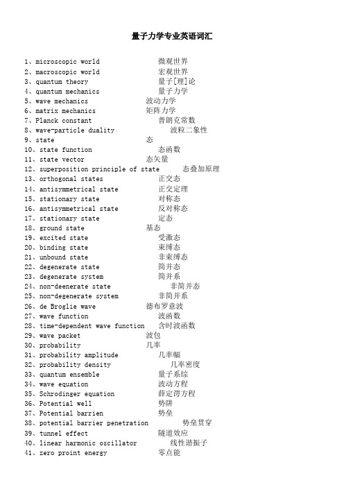
量子力学英语词汇

1、microscopic world 微观世界2、macroscopic world 宏观世界3、quantum theory 量子[理]论4、quantum mechanics 量子力学5、wave mechanics 波动力学6、matrix mechanics 矩阵力学7、Planck constant 普朗克常数8、wave-particle duality 波粒二象性9、state 态10、state function 态函数11、state vector 态矢量12、superposition principle of state 态叠加原理13、orthogonal states 正交态14、antisymmetrical state 正交定理15、stationary state 对称态16、antisymmetrical state 反对称态17、stationary state 定态18、ground state 基态19、excited state 受激态20、binding state 束缚态21、unbound state 非束缚态22、degenerate state 简并态23、degenerate system 简并系24、non-deenerate state 非简并态25、non-degenerate system 非简并系26、de Broglie wave 德布罗意波27、wave function 波函数28、time-dependent wave function 含时波函数29、wave packet 波包30、probability 几率31、probability amplitude 几率幅32、probability density 几率密度33、quantum ensemble 量子系综34、wave equation 波动方程35、Schrodinger equation 薛定谔方程36、Potential well 势阱37、Potential barrien 势垒38、potential barrier penetration 势垒贯穿39、tunnel effect 隧道效应40、linear harmonic oscillator 线性谐振子41、zero proint energy 零点能42、central field 辏力场43、Coulomb field 库仑场44、δ-function δ-函数45、operator 算符46、commuting operators 对易算符47、anticommuting operators 反对易算符48、complex conjugate operator 复共轭算符49、Hermitian conjugate operator 厄米共轭算符50、Hermitian operator 厄米算符51、momentum operator 动量算符52、energy operator 能量算符53、Hamiltonian operator 哈密顿算符54、angular momentum operator 角动量算符55、spin operator 自旋算符56、eigen value 本征值57、secular equation 久期方程58、observable 可观察量59、orthogonality 正交性60、completeness 完全性61、closure property 封闭性62、normalization 归一化63、orthonormalized functions 正交归一化函数64、quantum number 量子数65、principal quantum number 主量子数66、radial quantum number 径向量子数67、angular quantum number 角量子数68、magnetic quantum number 磁量子数69、uncertainty relation 测不准关系70、principle of complementarity 并协原理71、quantum Poisson bracket 量子泊松括号72、representation 表象73、coordinate representation 坐标表象74、momentum representation 动量表象75、energy representation 能量表象76、Schrodinger representation 薛定谔表象77、Heisenberg representation 海森伯表象78、interaction representation 相互作用表象79、occupation number representation 粒子数表象80、Dirac symbol 狄拉克符号81、ket vector 右矢量82、bra vector 左矢量83、basis vector 基矢量84、basis ket 基右矢85、basis bra 基左矢86、orthogonal kets 正交右矢87、orthogonal bras 正交左矢88、symmetrical kets 对称右矢89、antisymmetrical kets 反对称右矢90、Hilbert space 希耳伯空间91、perturbation theory 微扰理论92、stationary perturbation theory 定态微扰论93、time-dependent perturbation theory 含时微扰论94、Wentzel-Kramers-Brillouin method W. K. B.近似法95、elastic scattering 弹性散射96、inelastic scattering 非弹性散射97、scattering cross-section 散射截面98、partial wave method 分波法99、Born approximation 玻恩近似法100、centre-of-mass coordinates 质心坐标系101、laboratory coordinates 实验室坐标系102、transition 跃迁103、dipole transition 偶极子跃迁104、selection rule 选择定则105、spin 自旋106、electron spin 电子自旋107、spin quantum number 自旋量子数108、spin wave function 自旋波函数109、coupling 耦合110、vector-coupling coefficient 矢量耦合系数111、many-particle system 多子体系112、exchange forece 交换力113、exchange energy 交换能114、Heitler-London approximation 海特勒-伦敦近似法115、Hartree-Fock equation 哈特里-福克方程116、self-consistent field 自洽场117、Thomas-Fermi equation 托马斯-费米方程118、second quantization 二次量子化119、identical particles 全同粒子120、Pauli matrices 泡利矩阵121、Pauli equation 泡利方程122、Pauli’s exclusion principle泡利不相容原理123、Relativistic wave equation 相对论性波动方程124、Klein-Gordon equation 克莱因-戈登方程125、Dirac equation 狄拉克方程126、Dirac hole theory 狄拉克空穴理论127、negative energy state 负能态128、negative probability 负几率129、microscopic causality 微观因果性本征矢量eigenvector本征态eigenstate本征值eigenvalue本征值方程eigenvalue equation本征子空间eigensubspace (可以理解为本征矢空间)变分法variatinial method标量scalar算符operator表象representation表象变换transformation of representation表象理论theory of representation波函数wave function波恩近似Born approximation玻色子boson费米子fermion不确定关系uncertainty relation狄拉克方程Dirac equation狄拉克记号Dirac symbol定态stationary state定态微扰法time-independent perturbation定态薛定谔方程time-independent Schro(此处上面有两点)dinger equation 动量表象momentum representation角动量表象angular mommentum representation占有数表象occupation number representation坐标(位置)表象position representation角动量算符angular mommentum operator角动量耦合coupling of angular mommentum对称性symmetry对易关系commutator厄米算符hermitian operator厄米多项式Hermite polynomial分量component光的发射emission of light光的吸收absorption of light受激发射excited emission自发发射spontaneous emission轨道角动量orbital angular momentum自旋角动量spin angular momentum轨道磁矩orbital magnetic moment归一化normalization哈密顿hamiltonion黑体辐射black body radiation康普顿散射Compton scattering基矢basis vector基态ground state基右矢basis ket ‘右矢’ket基左矢basis bra简并度degenerancy精细结构fine structure径向方程radial equation久期方程secular equation量子化quantization矩阵matrix模module模方square of module内积inner product逆算符inverse operator欧拉角Eular angles泡利矩阵Pauli matrix平均值expectation value (期望值)泡利不相容原理Pauli exclusion principle氢原子hydrogen atom球鞋函数spherical harmonics全同粒子identical particles塞曼效应Zeeman effect上升下降算符raising and lowering operator 消灭算符destruction operator产生算符creation operator矢量空间vector space守恒定律conservation law守恒量conservation quantity投影projection投影算符projection operator微扰法pertubation method希尔伯特空间Hilbert space线性算符linear operator线性无关linear independence谐振子harmonic oscillator选择定则selection rule幺正变换unitary transformation幺正算符unitary operator宇称parity跃迁transition运动方程equation of motion正交归一性orthonormalization正交性orthogonality转动rotation自旋磁矩spin magnetic monent(以上是量子力学中的主要英语词汇,有些未涉及到的可以自由组合。
quantum transportation
量子通信应用
量子密钥分发:将量子通信原理仅用于用于发送密匙而不用于数据传 输。
Quantum Teleportation
In the quantum formalism, the result of a spin measurement on one of the particles is a collapse into a state in which each particle has a definite spin (either up or down) along the axis of measurement. The outcome is taken to be random, with each possibility having a probability of 50%. However, if both spins are measured along the same axis, they are found to be anti-correlated.
量子通信
Quantum Teleportation
量子通信
量子通信是指利用量子纠缠效应进行信息传递的一种新型的通讯方式, 是近二十年发展起来的新型交叉学科,是量子论和信息论相结合的新 的研究领域。
Quantum teleportation is a process by which quantum information (e.g. the exact state of an atom or photon) can be transmitted (exactly, in principle) from one location to another, with the help of classical communication and previously shared quantum entanglement between the sending and receiving location.
量子计算机常见术语简介(1)
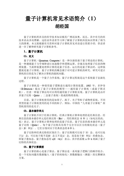
量子计算机常见术语简介(1)胡经国量子计算机所涉及的科学技术知识极其广博而深奥。
而且,其中有关的科技术语众多而费解。
这给业外读者学习和了解量子计算机科技知识带来了相当大的困难。
本文拟根据有关资料对量子计算机常见术语进行简要介绍,供读者进一步了解和研究量子计算机参考。
1、量子计算机⑴、定义量子计算机(Quantum Computer)是一种全新的基于量子理论的计算机,是一种遵循量子力学规律进行高速数学和逻辑运算、存储及处理量子信息的物理装置。
当某种装置处理和计算的是量子信息、运行的是量子算法时,这种装置就是量子计算机。
量子计算机的概念源于对可逆计算机的研究。
研究可逆计算机的目的是为了解决计算机的能耗问题。
量子计算机是一个量子力学系统;量子计算过程就是这个系统量子态演化过程。
量子计算机是一种使用量子逻辑进行通用计算的装置。
1985年,多伊奇(D.Deutsch)提出了量子计算机的模型——通用量子计算机(或量子图灵机)。
任意一种量子算法均可以利用通用量子计算机实现。
量子计算机是由许多量子比特(Qubit ,二态量子系统)组成的物理系统。
目前,量子计算机使用的是如原子、离子、光子等粒子或物理系统。
不同类型的量子计算机使用的是不同的粒子。
例如,中国的“九章量子计算机”原型机使用的是光子。
⑵、基本储存单元量子计算机不同于经典计算机。
经典计算机计算和处理的是经典信息。
经典信息的基本储存单元是经典比特(Bit),用经典状态0和1(如电压的高、低)表示。
量子计算机计算和处理的是量子信息。
量子信息的基本储存单元是量子比特(Qubit)。
每个量子比特具有两个完全可以区分的极化状态(量子态)|0〉和|1〉。
它们分别对应于经典状态的0和1。
量子比特和经典比特的区别在于:量子比特既可以处于|0〉态,也可以处于|1〉态;可以处于既不是|0〉态又不是|1〉态,而是处于|0〉和|1〉的叠加态,即量子叠加态。
量子叠加态用a|0〉+b|1〉表示;其中的系数a和b刻画了量子比特的具体状态。
滤波器的英文介绍
The basic principle of spread spectrum communicationSo-called spread spectrum communication, but simply indicates as follows: The "wide frequency communication is one intelligence transmission mode, its signal cabin holds the bandwidth far is bigger than passes on the information essentially the minimum bandwidth ; The frequency band expansion is completes through an independent code sequence, implements with the code and the modulation method, with passes on the information data to have nothing to do with; Uses the similar code in the receiving end to carry on the correlation synchronization receive, demodulation and recover passes on information data ".The wide frequency communication essential feature, is transmits the minimum bandwidth which the signal cabin takes (W) far to be bigger than (B) which primary information itself actual needs, its ratio is called the processing gain (Gp): In brief, we use the spread spectrum the wide band signal to transmit the information, is for enhance the communication the antijamming ability, namely under strong interferes the condition guaranteed the reliable security communicates. This is the spread spectrum communication basic thought and the theory basis.First, the main merit of wide frequency communications system* It’s easy to duplicate the frequency of use, raise the wireless frequency spectrum use factor* Strong anti-jamming, the error rate is low. Wide frequency communication when spatial transmission holds the bandwidth relative is wider, but the receiving end uses the correlation detection the means to solve expands, makes the useful wide band information signal to recover the narrow band signal, but non- needs the signal to expand the wide band signal, then extracts the useful signal through the narrow band filtering technology. This auspicious, regarding each kind of unwanted signal, because it in receives the end the non- relevance, after demodulation in the narrow band signal only has the very weak ingredient, the signal to noise ratio very high, therefore the anti-jamming is strong.* Good Privacy, is very small to each kind of narrow band communications system disturbance. Because the wide frequency signal expanded in the relative wider frequency band, in unit frequency band power very small, the signal is neglected in the noise, generally not easily was detected, but wants further to examine the signal the parameter (for example pseudo-random code sequence) difficultly, therefore said its privacy is good.* May implement a code minute site. The wide frequency communication enhanced the resistance to interference, the price takes the band width. But if many usersaltogether use this wideband, then may enhance the frequency band the use factor. Because has the wide frequency code sequence in the wide frequency communication the wide frequency modulation, fully uses between each kind of different code wide frequency code sequence the fine autocorrelation identity and the mutual correlation identity, carries on the solution in the receiving end using the correlation detection technology to expand, then in allocate may differentiate the different user for the different user code situation in the signal, extracts the useful signal. Like this many pair of users may simultaneously converse on the telephone in this frequency band but mutually does not disturb.* Anti- multi- diameters disturbance. In the wireless communication, since long ago, the multi- diameters disturbance throughout is one of questions which solves with difficulty. Uses the wide frequency code in the wide frequency communication the autocorrelation identity, extracts and separates the strongest useful signal in the receiving end from the multi- diameters signal, or the identical code sequence profile which comes many paths adds together the synthesis, all may the anti- multi- diameters disturbance function.Be different according to the spread spectrum mode, the existing wide frequency communications system may divide into following several kinds:* Direct sequence spread spectrum. The direct sequence spread spectrum (Direct Sequence Spread Spectrum) the work mode, is called straight expands (DSSS) the mode. The so-called direct sequence spread spectrum, is directly use the high rate wide frequency code sequence to expand the signal in the start the frequency spectrum. But in the receiving end, carries on the solution with the same wide frequency code sequence to expand, returns to original state the primitive information the stretch wide frequency signal.* Frequency-hopping (Frequency Hopping). Moreover one expansion signal frequency spectrum mode is called the frequency-hopping (FH - Frequency Hopping). The so-called frequency-hopping, compared with the accurate meaning is: Carries on the selection with the certain code sequence the multi- frequencies frequency-shift keying. In other words, carries on the frequency-shift keying modulation with the wide frequency code sequence, causes the carrier frequency unceasingly to jump, therefore is called the frequency-hopping.* Jumps when (Time Hopping). Is similar, jumps when (TH – Time Hopping) with the frequency-hopping is causes the transmitting message to jump in the time axis. First divides into the time axis many o'clock pieces. In does an in which time piece transmitting message carry on the check by the wide frequency code sequence. May jumps when the understanding be: Carries on selection with the certain code sequence many when pieces when moves the key modulation. Because used has very been narrow the very many time piece to transmit the signal, relatively mentioned, thesignal frequency spectrum also stretched.* Wide band linear frequency modulation (Chirp Modulation). The wide band linear frequency modulation work mode, is called the Chirp mode. If emanates radio frequency pulse signal in a cycle, its carrier spectrum frequency do change, then is called the linear frequency modulation.Second, direct sequence spread spectrum systemCompares with the general simulation or the digital communication system, the direct sequence spread spectrum in the information recognition and the demodulation, the radio frequency on frequency conversion and under the frequency conversion situation basic is same. Straight expands the communications system the main characteristic to lie in straight expands the signal the production, namely the wide frequency modulation and straight expands the signal the receive, namely the related solution expands.The wide frequency modulation is carries on the modulation with high rate PN code pulse sequence thus the expansion signal frequency spectrum. Usually uses the modulation mode is BPSK, the input signal and the PN code modulates in the balanced modulator outputs the stretch the wide frequency signal.Straight expands the system to carry on the modulation in the start with the PN code to expand the signal frequency spectrum. Is receiving the end generally to use the correlation detection or the matched filtering method solves expands. The so-called correlation detection, a simple metaphor is compares with the picture looks for the person. If wants to search the person in group of people which some is not acquainted with one another, the simplest valid method is in the hand has a Zhang person's picture, then with the picture one by one contrast, gets down like this, naturally can find some person. Same principle, when you want to examine the useful signal which needs, the valid method is in local produces a same signal, then with it with the signal contrast which receives, as desired similarity. In other words, is with the same signal which local produces with the signal which receives carries on the correlation operation, correlation function is biggest on the useful signal which most possibly is wants.The connected demodulation to be no doubt very good in the performance, but it needs to have the local PN code in the receiving end. This point sometimes brings many is not convenient. For example, the solution local signal and the receive signal synchronized question very is troublesome, but also cannot achieve real-time examines the useful signal. Because the matched filtering and the correlationdetection function in essentially is same, we may use the matched filter to demodulate t the straight -expand signal.The so-called matched filter, is a filter which matches with the signal, it can examines in the many kinds of signals or the disturbance with it match signal. This similarly is one kind of "looks for person" with the photograph the method. As for the video frequency rectangle pulse sequence that, the passive matched filter is on the tap delay line adds on the adder-accumulator.Third, frequency-hopping systemWe usually contact the wireless communications system all is the carrier frequency fixed communications system, like mobile phone and so on, therefore also is called as decides the frequency communication. This kind decides the frequency communications system, once will receive the disturbance on to cause the communication drop in quality, will be serious when will even cause the communication interrupt.Moreover in the enemy I in the duplex communication resistance, the enemy side attempt detects our communication frequency, in order to transmits to the interception the information content, or detected our telegraph is at position. Decides the frequency communications system to be easy to expose the goal also easy to intercept, by now, used the frequency-hopping communications quite to be covert with difficulty is also intercepted.Therefore, the frequency-hopping communications has the antijamming, the anti- interception ability, and can do frequency spectrum resource sharing. Therefore the frequency-hopping communications has displayed the huge superiority in the current modernized electronic warfare. Moreover, the frequency-hopping communications also applies in the civil communication by between the anti- decline, the anti- multi- diameters, the anti- network disturbs and raises the frequency spectrum use factor.In order to does not let the enemy side know we communicate the use frequency, needs frequently to change the carrier frequency, namely carries on the jump to the carrier frequency, in the frequency-hopping communications the carrier frequency change rule, is called the frequency-hopping design.The frequency-hopping signal receive, its process with decides the frequency to be similar. In order to after guarantee the mixing obtains the intermediate frequency signal, the requirement frequency synthesizer output frequency must outdo an intermediate frequency compared to the external signal. Because the external signal-carrier frequency is the jump, then requires the frequency which the local frequency synthesizer outputs also along with the external signal jump rule to jump, like this can obtain a fixed center quite signal through the mixing.The frequency-hopping is the frequency-hopping system key component, but frequency-hopping synchronization is the frequency-hopping system core technology. Frequency-hopping system synchronization including following several contents:* Receives the frequency-hopping design which the end and the start produces to be same, namely has the same frequency-hopping rule.* Receives, the start jump frequency should guarantee produces the fixed intermediate frequency signal in the receiving end, namely the jump carrier frequency with receives this locality which the end produces to jump the frequency to differ an intermediate frequency.* Frequency jump beginning and end time in time synchronization, namely synchronized jump, or phase coincidence.* When transmission numerical information, but also should achieve the frame synchronization and position synchronization.Fourth, PN codeThe PN code also calls the pseudo-random sequence. It has the approximate random sequence (noise) nature, but also can (cycle) produce according to the certain rule with the copying sequence. Because the random sequence is only can produce but cannot copy, therefore called it is the "pseudo" random sequence. The commonly used pseudo-random sequence has the m sequence, the M sequence and R –the S sequence.The msequencer from the belt feedback m level shift register framing,feeds back from certain levels after mold two Canada to the first level. It produces the sequence greatest length (cycle) is the 2n – 1 bit, altogether has 2m to plant the different state, one kind is entire "0" state. Only has when the feedback logic satisfies some kind of condition, the shift register outputs the sequence length is the 2n - 1 bit, achieves the greatest length. Otherwise produces the sequence could not achieve 2n - 1 bit of such is long. Therefore also is called the m sequence the greatest length linearity shift register sequence. Also is called the biggest shift register sequence.If in the feedback logic operation includes the multiplication operation or other logic operations, then is called as the nonlinear feedback logic. The sequencer frame which by the nonlinear feedback logic and the shift register can have the greatest length sequence, is called the greatest length non-linearity shift register sequence, or is called the M sequence, the M sequence greatest length is 2n.。
量子力学英语词汇

1、microscopic world 微观世界2、macroscopic world 宏观世界3、quantum theory 量子[理]论4、quantum mechanics 量子力学5、wave mechanics 波动力学6、matrix mechanics 矩阵力学7、Planck constant 普朗克常数8、wave-particle duality 波粒二象性9、state 态10、state function 态函数11、state vector 态矢量12、superposition principle of state 态叠加原理13、orthogonal states 正交态14、antisymmetrical state 正交定理15、stationary state 对称态16、antisymmetrical state 反对称态17、stationary state 定态18、ground state 基态19、excited state 受激态20、binding state 束缚态21、unbound state 非束缚态22、degenerate state 简并态23、degenerate system 简并系24、non-deenerate state 非简并态25、non-degenerate system 非简并系26、de Broglie wave 德布罗意波27、wave function 波函数28、time-dependent wave function 含时波函数29、wave packet 波包30、probability 几率31、probability amplitude 几率幅32、probability density 几率密度33、quantum ensemble 量子系综34、wave equation 波动方程35、Schrodinger equation 薛定谔方程36、Potential well 势阱37、Potential barrien 势垒38、potential barrier penetration 势垒贯穿39、tunnel effect 隧道效应40、linear harmonic oscillator线性谐振子41、zero proint energy 零点能42、central field 辏力场43、Coulomb field 库仑场44、δ-function δ-函数45、operator 算符46、commuting operators 对易算符47、anticommuting operators 反对易算符48、complex conjugate operator 复共轭算符49、Hermitian conjugate operator 厄米共轭算符50、Hermitian operator 厄米算符51、momentum operator 动量算符52、energy operator 能量算符53、Hamiltonian operator 哈密顿算符54、angular momentum operator 角动量算符55、spin operator 自旋算符56、eigen value 本征值57、secular equation 久期方程58、observable 可观察量59、orthogonality 正交性60、completeness 完全性61、closure property 封闭性62、normalization 归一化63、orthonormalized functions 正交归一化函数64、quantum number 量子数65、principal quantum number 主量子数66、radial quantum number 径向量子数67、angular quantum number 角量子数68、magnetic quantum number 磁量子数69、uncertainty relation 测不准关系70、principle of complementarity 并协原理71、quantum Poisson bracket 量子泊松括号72、representation 表象73、coordinate representation 坐标表象74、momentum representation 动量表象75、energy representation 能量表象76、Schrodinger representation 薛定谔表象77、Heisenberg representation 海森伯表象78、interaction representation 相互作用表象79、occupation number representation 粒子数表象80、Dirac symbol 狄拉克符号81、ket vector 右矢量82、bra vector 左矢量83、basis vector 基矢量84、basis ket 基右矢85、basis bra 基左矢86、orthogonal kets 正交右矢87、orthogonal bras 正交左矢88、symmetrical kets 对称右矢89、antisymmetrical kets 反对称右矢90、Hilbert space 希耳伯空间91、perturbation theory 微扰理论92、stationary perturbation theory 定态微扰论93、time-dependent perturbation theory 含时微扰论94、Wentzel-Kramers-Brillouin method W. K. B.近似法95、elastic scattering 弹性散射96、inelastic scattering 非弹性散射97、scattering cross-section 散射截面98、partial wave method 分波法99、Born approximation 玻恩近似法100、centre-of-mass coordinates 质心坐标系101、laboratory coordinates 实验室坐标系102、transition 跃迁103、dipole transition 偶极子跃迁104、selection rule 选择定则105、spin 自旋106、electron spin 电子自旋107、spin quantum number 自旋量子数108、spin wave function 自旋波函数109、coupling 耦合110、vector-coupling coefficient 矢量耦合系数111、many-partic le system 多子体系112、exchange forece 交换力113、exchange energy 交换能114、Heitler-London approximation 海特勒-伦敦近似法115、Hartree-Fock equation 哈特里-福克方程116、self-consistent field 自洽场117、Thomas-Fermi equation 托马斯-费米方程118、second quantization 二次量子化119、identical particles全同粒子120、Pauli matrices 泡利矩阵121、Pauli equation 泡利方程122、Pauli’s exclusion principle泡利不相容原理123、Relativistic wave equation 相对论性波动方程124、Klein-Gordon equation 克莱因-戈登方程125、Dirac equation 狄拉克方程126、Dirac hole theory 狄拉克空穴理论127、negative energy state 负能态128、negative probability 负几率129、microscopic causality 微观因果性本征矢量eigenvector本征态eigenstate本征值eigenvalue本征值方程eigenvalue equation本征子空间eigensubspace (可以理解为本征矢空间)变分法variatinial method标量scalar算符operator表象representation表象变换transformation of representation表象理论theory of representation波函数wave function波恩近似Born approximation玻色子boson费米子fermion不确定关系uncertainty relation狄拉克方程Dirac equation狄拉克记号Dirac symbol定态stationary state定态微扰法time-independent perturbation定态薛定谔方程time-independent Schro(此处上面有两点)dinger equation 动量表象momentum representation角动量表象angular mommentum representation占有数表象occupation number representation坐标(位置)表象position representation角动量算符angular mommentum operator角动量耦合coupling of angular mommentum对称性symmetry对易关系commutator厄米算符hermitian operator厄米多项式Hermite polynomial分量component光的发射emission of light光的吸收absorption of light受激发射excited emission自发发射spontaneous emission轨道角动量orbital angular momentum自旋角动量spin angular momentum轨道磁矩orbital magnetic moment归一化normalization哈密顿hamiltonion黑体辐射black body radiation康普顿散射Compton scattering基矢basis vector基态ground state基右矢basis ket ‘右矢’ket基左矢basis bra简并度degenerancy精细结构fine structure径向方程radial equation久期方程secular equation量子化quantization矩阵matrix模module模方square of module内积inner product逆算符inverse operator欧拉角Eular angles泡利矩阵Pauli matrix平均值expectation value (期望值)泡利不相容原理Pauli exclusion principle氢原子hydrogen atom球鞋函数spherical harmonics全同粒子identical partic les塞曼效应Zeeman effect上升下降算符raising and lowering operator 消灭算符destruction operator产生算符creation operator矢量空间vector space守恒定律conservation law守恒量conservation quantity投影projection投影算符projection operator微扰法pertubation method希尔伯特空间Hilbert space线性算符linear operator线性无关linear independence谐振子harmonic oscillator选择定则selection rule幺正变换unitary transformation幺正算符unitary operator宇称parity跃迁transition运动方程equation of motion正交归一性orthonormalization正交性orthogonality转动rotation自旋磁矩spin magnetic monent(以上是量子力学中的主要英语词汇,有些未涉及到的可以自由组合。
Importance of quantum interference in molecular-scale devices
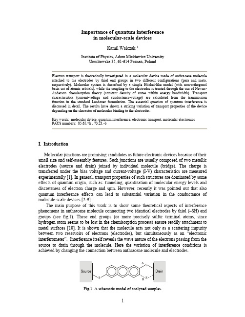
Importance of quantum interferencein molecular-scale devicesKamil Walczak 1Institute of Physics, Adam Mickiewicz UniversityUmultowska 85, 61-614 Poznań, PolandElectron transport is theoretically investigated in a molecular device made of anthracene molecule attached to the electrodes by thiol end groups in two different configurations (para and meta, respectively). Molecular system is described by a simple Hückel-like model (with non-orthogonal basis set of atomic orbitals), while the coupling to the electrodes is treated through the use of Newns-Anderson chemisorption theory (constant density of states within energy bandwidth). Transport characteristics (current-voltage and conductance-voltage) are calculated from the transmission function in the standard Landauer formulation. The essential question of quantum interference is discussed in detail. The results have shown a striking variation of transport properties of the device depending on the character of molecular binding to the electrodes.Key words: molecular device, quantum interference, electronic transport, molecular electronicsPACS numbers: 85.65.+h , 73.23.-bI. IntroductionMolecular junctions are promising candidates as future electronic devices because of their small size and self-assembly features. Such junctions are usually composed of two metallic electrodes (source and drain) joined by individual molecule (bridge). The charge is transferred under the bias voltage and current-voltage (I-V) characteristics are measured experimentally [1]. In general, transport properties of such structures are dominated by some effects of quantum origin, such as: tunneling, quantization of molecular energy levels and discreteness of electron charge and spin. However, recently it was pointed out that also quantum interference effects can lead to substantial variation in the conductance of molecule-scale devices [2-9].The main purpose of this work is to show some theoretical aspects of interference phenomena in anthracene molecule connecting two identical electrodes by thiol (–SH) end groups (see fig.1). These end groups (or more precisely sulfur terminal atoms, since hydrogen atom seems to be lost in the chemisorption process) ensure readily attachment to metal surfaces [10]. It is shown that the molecule acts not only as a scattering impurity between two reservoirs of electrons (electrodes), but simultaneously as an “electronic interferometer”. Interference itself reveals the wave nature of the electrons passing from the source to drain through the molecule. Here the variation of interference conditions is achieved by changing the connection between anthracene molecule and electrodes.Fig.1 A schematic model of analyzed samples.II. Theoretical treatmentMolecular device is defined as anthracene molecule joined to two metallic surfaces with the help of thiol end groups in two different configurations – para (A) and meta (B), respectively. In both cases we have different interference conditions and so we expect to observe changes in transport characteristics. Problem of electronic conduction between two continuum reservoirs of states via a molecular bridge with discrete energy levels can be solved within transfer matrix technique of scattering theory [11,12]. The current flowing through the device is obtained from the transmission function T through the integration procedure [12]: []dE )E (f )E (f )E (T h e 2)V (I D S m m ---=ò+¥¥-, (1)where: f denotes Fermi distribution function for room temperature (293 K) with chemical potentials 2/eV E F D /S ±=m referred to the source and drain, respectively. In this type of non-self-consistent calculations, one must postulate voltage distribution along the molecular bridge. For the sake of simplicity we assume that voltage drop is limited to the electrodes only [13], shifting their Fermi level located in the middle of the HOMO-LUMO gap [14]. However, other choices of the voltage distribution have only a small effect on our final results and general conclusions. The differential conductance is then calculated as the derivative of the current with respect to the voltage [15]:[])(T )(T G G D S 021m m +=, (2) where 5.77h /e 2G 20»= [μS] is the quantum of conductance.Formula for the transmission probability can be expressed in the convenient matrix form[12]:[]+++--=G )(G )(tr )E (T D D S S S S S S , (3)where D /S S and are self-energy terms of the source/drain electrode and the Green ’s function of the molecule is expressed as follows:1D S ]H ES [G ----=S S . (4)Here S denotes overlapping matrix (where the overlap between the nearest-neighbor sites is assumed to be equal to 0.25). Since only delocalized π-electrons dictate the transport properties of organic molecules, the electronic structure of the molecule is described by a simple H ückel Hamiltonian H with one π-orbital per site (atom) [16], where overlapping is explicitly included (using non-orthogonal basis set of atomic orbitals). Throughout this work we take the standard energy parameters for organic conjugated systems: on-site energy is 6.6-=a eV and nearest-neighbor hopping integral is 7.2-=b eV. In the H ückel π-bond picture, all carbon and sulfur atoms are treated equivalently (because of their electronegativity). In our simplified model, the coupling to the electrodes is treated through the use of Newns-Anderson chemisorption theory [11], where ideal electrodes are described by constant density of states within energy bandwidth [17-20]. So self-energy matrices (S ) take the diagonal form with elements equal to i 05.0- [eV].Fig.2 Transmission as a function of electron energy (with respect to Fermi energy level)for devices in configuration A (solid curve) and B (broken curve), respectively.Fig.3 Comparison of conductance spectra for devices in configurationA (solid curve) andB (broken curve), respectively. III. Results and discussionNow we proceed to analyze our results from the point of view of quantum interference effects. The geometry of the molecule is taken to be that of anthracene with sulfur atoms on either end of the molecule, binding it to the electrodes in two different configurations – para(A) and meta (B), respectively. For isolated anthracene the HOMO is at 614.7- eV and the LUMO is at 352.5- eV. Because of our simplification that Fermi level is arbitrarily chosen to be located in the middle of the HOMO-LUMO gap, 483.6E F -= eV. The HOMO-LUMO gap for molecular system in para configuration is reduced from 262.2 eV for anthracene to the value of 667.0 eV, but for molecular system in meta configuration it is reduced to zero.Figure 2 shows the transmission dependence on the electron energy for anthracene in para (A) and meta (B) connections with identical electrodes. For transparency we plot it in the logarithmic scale. Asymmetry of the transmission function (with respect to the Fermi energy level) is due to non-orthogonality of atomic orbitals used to describe molecular system. The existence of resonances in the transmission probability is associated with resonant tunneling through molecular eigenstates. Such resonance peaks are shifted and broadened by the fact of the coupling with the electrodes (just like discrete energy levels of the molecule). A change in the configuration of connection between anthracene and two electrodes results in variation of the interference conditions and obvious changes in the transmission function. It manifests itself as shifts in the resonance peaks and in reduction of their height. Well-separated energy levels give rise to distinct peaks in the spectrum, while molecular levels close in energy can overlap and eventually interfere (reduction of resonance peaks is due to destructive interference).Fig.4 Comparison of current-voltage characteristics for devices in configurationA (solid curve) andB (broken curve), respectively.Another remarkable feature of the transmission spectrum is the appearance of antiresonances, which are defined as transmittance zeros and correspond to the physical situation for incident electron being perfectly reflected by a molecule. There are two different mechanisms (well-known in literature) responsible for the origin of antiresonances. One of these is associated with interference between the different molecular orbitals through which the electron propagates [2,21]. The second mechanism is due entirely to the non-orthogonality of atomic orbitals on different atoms [17]. In principle, transport problem in which a non-orthogonal basis set of states is used can be solved by a method proposed recently by Emberly and Kirczenow [5], where condition for antiresonances was analytically demonstrated. However, in this work we perform numerical evaluations of energies at which incoming electron has no chance to leave the source electrode. There are six antiresonances for device in configuration A (F E 821.2E +-=, F E 160.2+-, F E 622.1+-, F E 320.2+,F E 600.3+, F E 907.5+) and only one for device in configuration B (F E E =). Antiresonance is predicted to manifest itself by producing a drop in the differential conductance [5]. Moreover, the fact that it is generated exactly at the Fermi energy of metallic electrodes has important consequences for the conductance spectrum in which antiresonance can be observed (as shown in fig.3). However, in practice this unusual phenomenon can be blurred by some neglected factors which are present in realistic systems, such as: Stark effect, σ states, σ-π hybridization or many-body effects.In figure 4 we plot the current-voltage (I-V) characteristics for both analyzed structures (in para – A and meta – B connections, respectively). The current steps are attributed to the discreteness of molecular energy levels as modified by the coupling with the electrodes [12]. Because this coupling is assumed to be small (bad contacts are suggested by experimental data [1]), the transmission peaks are very narrow and therefore the I-V dependence has a step-like character. In particular, the height of the step in the I-V curve is directly proportional to the area of the corresponding peak in the transmission spectrum. Since quantum interference is important in determining the magnitudes of the resonance peaks, it is also crucial for calculations of the tunneling current. Indeed, the magnitude of the current flowing through the device is very sensitive on the manner of attachment between anthracene molecule and metal surfaces. Large values of the current are predicted for device of configuration A, while reduction of the current by orders of magnitude is expected for device of configuration B (although the shape of the I-V curve is similar in both cases). Such reduction is caused by destructive interference.IV. SummaryIn this paper we have examined the possibility that quantum interference can substantially affect the conductance in molecular-scale devices. The results have shown a striking variation of all the transport characteristics depending on the geometry of the molecular system (its connection with the electrodes). Anyway, the quantum effect of destructive interference may be used within the molecular device to switch its conductivity on and off [8,9]. The existence of interference effects in molecular devices open the question of their control. The phase shift of molecular orbitals could be controlled by a transverse magnetic field or a longitudinal electric field. However, magnetic field seems to be too large to produce significant phase shift (according to our simulations – hundreds of Teslas). AcknowledgmentsAuthor is very grateful to B. Bułka, T. Kostyrko and B. Tobijaszewska for illuminating discussions. Special thanks are addressed to S. Robaszkiewicz for his stimulating suggestions.References1E-mail address: walczak@.pl[1] M. A. Reed, Proc. IEEE 87, 625 (1999) and references therein.[2] P. Sautet, C. Joachim, Chem. Phys. Lett. 153, 511 (1988).[3] V. Marvaud, J. P. Launay, C. Joachim, Chem. Phys. 177, 23 (1993).[4] M. N. Paddon-Row, K. D. Jordan, J. Am. Chem. Soc. 115, 2952 (1993).[5] E. Emberly, G. Kirczenow, J. Phys.: Condens. Matter 11, 6911 (1999).[6] M. Magoga, C. Joachim, Phys. Rev. B 59, 16011 (1999).[7] C. Untiedt, G. Rubio Bollinger, S. Vieira, N. Agraït, Phys. Rev. B 62, 9962 (2000).[8] R. Baer, D. Neuhauser, J. Am. Chem. Soc. 124, 4200 (2002).[9] R. Baer, D. Neuhauser, Chem. Phys. 281, 353 (2002).[10] H. Sellers, A. Ulman, Y. Shnidman, J. E. Eilers, J. Am. Chem. Soc. 115, 9389 (1993).[11] V. Mujica, M. Kemp, M. A. Ratner, J. Chem. Phys. 101, 6849 (1994);ibid. 101, 6856 (1994); ibid. 104, 7296 (1996).[12] S. Datta, Electronic transport in mesoscopic systems, Cambridge University Press,Cambridge 1995.[13] S. Datta, W. Tian, S. Hong, R. Reifenberger, J. I. Henderson, C. P. Kubiak,Phys. Rev. Lett. 79, 2530 (1997).[14] S. N. Yaliraki, A. E. Roitberg, C. Gonzalez, V. Mujica, M. A. Ratner,J. Chem. Phys. 111, 6997 (1999).[15] W. Tian, S. Datta, S. Hong, R. Reifenberger, J. I. Henderson, C. P. Kubiak,J. Chem. Phys. 109, 2874 (1998).[16] E. G. Emberly, G. Kirczenow, Nanotechnology 10, 285 (1999).[17] M. Kemp, A. Roitberg, V. Mujica, T. Wanta, M. A. Ratner,J. Phys. Chem. 100, 8349 (1996).[18] L. E. Hall, J. R. Reimers, N. S. Hush, K. Silverbrook, J. Chem. Phys. 112, 1510 (2000).[19] J. E. Han, V. H. Crespi, Appl. Phys. Lett. 79, 2829 (2001).[20] S. T. Pantelides, M. Di Ventra, N. D. Lang, Physica B 296, 72 (2001).[21] A. Cheong, A. E. Roitberg, V. Mujica, M. A. Ratner,J. Photochem. Photobiol. A 82, 81 (1994).。
霍尔效应及其相关效应

由于一个电 子现在附着了 三个量子磁通, 这就解释了分 数量子霍尔效 应中的 n=1/3. 示意图如上, 穿 过电子的三根 线即为三个量 子磁通.
Quantum Hall Effects
M. O. Goerbig (Submitted on 10 Sep 2009 (v1), last revised 21 Oct 2009 (this version, v2)) These lecture notes yield an introduction to quantum Hall effects both for non-relativistic electrons in conventional 2D electron gases (such as in semiconductor heterostructures) and relativistic electrons in graphene. After a brief historical overview in chapter 1, we discuss in detail the kinetic-energy quantisation of non-relativistic and the relativistic electrons in a strong magnetic field (chapter 2). Chapter 3 is devoted to the transport characteristics of the integer quantum Hall effect, and the basic aspects of the fractional quantum Hall effect are described in chapter 4. In chapter 5, we briefly discuss several multicomponent quantum Hall systems, namely the quantum Hall ferromagnetism, bilayer systems and graphene that may be viewed as a four-component system. Comments: 102 pages; lecture notes for the Singapore session ``Ultracold Gases and Quantum Information'' of Les Houches Summer School, 2009; v2 contains minor corrections and additional references Subjects: Mesoscale and Nanoscale Physics (cond-mat.mes-hall); Strongly Correlated Electrons (cond-mat.str-el) Cite as: arXiv:0909.1998 [cond-mat.mes-hall] (or arXiv:0909.1998v2 [cond-mat.mes-hall] for this version) Submission history From: M. O. Goerbig [view email] [v1] Thu, 10 Sep 2009 17:38:01 GMT (1867kb) [v2] Wed, 21 Oct 2009 09:06:49 GMT (1858kb)
The Unitary Transformation in Quantum Teleportation
a r X i v :q uant-ph/064195v126A pr26The Unitary Transformation in Quantum Teleportation Zheng-Chuan Wang Department of Physics,The Graduate School of the Chinese Academy of Sciences,P.O.Box 4588,Beijing 100049,China.February 1,2008Abstract In the well known treatment of quantum teleportation,the receiver should convert the state of his EPR particle into the replica of the un-known quantum state by one of four possible unitary transformations.However,the importance of these unitary transformations must be em-phasized.We will show in this paper that the receiver can not trans-form the state of his particle into an exact replica of the unknown state which the sender want to transfer if he have not a proper implementation of these unitary transformations.In the procedure of converting state,the inevitable coupling between EPR particle and environment which is needed by the implementation of unitary transformations will reduce the accuracy of the replica.03.67.Hk,03.67.-a,03.65.Ta..In 1993,Bennett et al.[1]proposed a famous treatment to transfer an intact quantum state from one place to another by use of the long-range correlation between EPR pair of particles.In their scheme,an unknown state and one of EPR particles are given to the sender,and the sender then perform a complete measurement on the joint system of the unknown state and her EPR state.After this,the receiver will perform a unitary transformation on the second particle ofthe EPR pair to obtain the replica of the unknown state,certainly,this unitary transformation is determined by the results of measurement told by the sender through a classical channel.The experimental realizations of their treatment were exhibited by Bouwmeester et al.[2]and Boschi et al.[3],respectively,in which an initial photon which carries the polarization is transferred by use of a pair of entangled photons prepared in an EPR state.These approaches to quantum teleportation had inspired many investigations into this field,such as the discussions of continuous variable quantum teleportation[4,5,6],the analysis of quantum fluctuation in the teleportation[7]etc.However,it should be pointed out that the physical implementation of the unitary transformations on the second EPR particle should be noticed,they1are not mere the pure mathematical transformations,we need realize these uni-tary transformations by other physical systems.For convenience,we summarily call these system′environment′.The inevitable interaction between EPR par-ticle in the hands of receiver and the environment will affect the replica of theunknown state.Even worse,if we have not properly chosen the physical real-ization of these unitary transformations,the unknown quantum state will not be teleported enough accurately because of the influence of environment.Suppose a sender,traditionally called′Alice′,who wish to communicate an unknown quantum state|Ψ =a|0 +b|1 of spin-1/2particle(particle1)to a receiver,′Bob′.Two other spin-1/2particles are prepared in an EPR singlet state.According to Bennett et al.′s treatment,one EPR particle(particle2)is given to Alice,the other(particle3)is given to Bob.Alice makes a combined measurement on her EPR particle2and the unknown particle1,then Bob′s particle3will be in one of the following four pure states:-a|0 3−b|1 3,-a|0 3+b|1 3,b|0 3+a|1 3,and-b|0 3+a|1 3.In the ideal case,Bob can convert the state of particle3into an exact replica of the initial state|Ψ =a|0 +b|1 by a unitary transformation which depends on the results of measurement told by Alice via classical channel.However,these unitary transformations must be performed through other physical systems or apparatus,which can be summarily described as′environment′,then the interaction between particle3and the ′environment′occurs,which will couple the quantum state of environment with particle3and violate the accurate replica of the initial quantum state|Ψ .In fact,the above interaction between particle3and environment makes the quantum state of the combined system(particle3-environment)evolves as follows[8]|Φ(t=t0) =|E0 ⊗|Ψ 3(1)−→|Φ(t>t1) =C0a|E0 |0 3+C1b|E1 |1 3.In the above,|E0 ,|E1 are the state vectors of environment,while|Ψ 3de-scribes the quantum state of particle3.As a result of particle3-environment interaction,the correlation between particle and environment has been estab-lished after time t1,the state vectors of particle3and environment have coupled to each other after time t1.Expression(1)clearly demonstrates the violation of pure state|Ψ 3after the practical implementation of unitary transformations. We can also show this violation by its density matrix.The reduced density matrix of particle3isρ3=T r E[|Φ(t>t1) Φ(t>t1)|](2) =(|C0a|2+|C0a|2| E1|E0 |2)|0 0|+(2C0C∗1ab∗ E1|E0 )|0 1| +(2C1C∗0ba∗ E0|E1 )|1 0|+(|C1b|2+|C1b|2| E0|E1 |2)|1 1|. When the state vectors|E0 ,|E1 of environment are orthogonal to each other,2the density matrix can reduce toρ3=|C0a|2|0 0|+|C1b|2|1 1|,(3) which indicates pure state|Ψ 3has become to a mixture state.Generally,the pure state|Ψ 3of Bobs EPR particle will reduce to a mixture state after a practical realization of unitary transformations,in the end Bob can not obtain a pure state of particle3,and can not convert|Ψ 3into the initial pure state |Ψ which Alice sought to teleport.An unknown quantum state can thus not be teleported enough accurately because of the physical implementation of unitary transformations.In the general,there exists deviation between the replica of unknown state in the hands of Bob after practical unitary transformation and the initial quantum state|Ψ 1prepared by Alice.We can evaluate the above deviation by the difference betweenρ3and the density matrixρ1of pure state|Ψ 1,it isδ=√√a|A 0|0 |0 +b|A 1|1 |1 ,where|A i(i=0,1)are the quantum state vectors of apparatus,and the new state vectors|0 and|1 in the outcome are pro-vided by the environment.There are correlation between the unknown state and the state vectors of environment.The general state vectors of environ-ment|A i|i (i=0,1)just correspond to the state vectors C i|E i (i=0,1)of environment in expression(1).So our above analysis is equivalent to quantum non-cloning theorem,it is the environment that leads to the impossibility for an unknown state being cloned accurately,the interaction of particle and envi-ronment will cause the decoherence of pure state of particle to a mixture state. To teleport an unknown quantum state enough accurately will eventually break the quantum non-cloning theorem because of the influence of environment.In summary,we have shown that an unknown quantum state can not be teleported enough accurately from one place to another when we consider the practical physical implementation of unitary transformations except some spe-cial cases.The coupling of environment and particle will reduce the accuracy of converting procedure,it is another manifest of quantum non-cloning theorem.AcknowledgmentsThis work is supported by the NNSF(Grant No.10404037). References[1]C.H.Bennett,G.Brassard,C.Crepeau,R.Jozsa,A.Peres and W.K.Wootters,Phys.Rev.Lett.70,1895(1993).[2]D.Bouwmeester,J.Pan,K.Mattle,M.Eibl,H.Weinfurter and A.Zeilinger,Nature,390,575(1997).[3]D.Boschi,S.Branca,F.De Martini,L.Hardy and S.Popescu,Phys.Rev.Lett.,80,1121(1998).[4]A.Furusawa,J.L.Sorensen,S.L.Braunstein,C.A.Fuchs,H.J.Kimbleand E.S.Polzik,Science,282,706(1998).[5]S.L.Braunstein and H.J.Kimble,Phys.Rev.Lett,80,869(1998).[6]H.Yonezawa,T.Aoki and A.Furusawa,Nature,431,430(2004).[7]R.E.S.Polinghorne and T.C.Ralph,Phys.Rev.Lett.83,2095(1999).[8]W.H.Zurek,Phys.Rev.D26,1862(1982).[9]W.K.Wootters and W.H.Zurek,Nature,299,802(1982).4。
电子信息工程专业英语 课文翻译 Unit 04 译文

Unit 4 通信和信息论Unit 4-1第一部分:远程通信远程通信是远距离通信的信号传输,在现代,通常这个过程需要电子发射机发射电磁波,但是在早期远程通信包括使用烟火信号,鼓或旗语或日光仪。
今天,远程通信很普遍的,助推这一过程的设备如电视,无线电和电话在世界的许多地区都已很普遍。
还有连接这些设备的许多网络,包括计算机网络,公共电话网,无线电网和电视网络。
互联网上的计算机通信是众多通信的一个例子。
通信系统通常由通信工程师设计。
在这个领域中早期的发明家有Alexander Graham Bell, Guglielmo Marconi 和John Logie Baird。
通信在当今的世界经济发展中起着举足轻重的作用,通信产业的税收在世界总产值的比例已接近百分之三。
基本要素每个通信系统包括三个基本要素:采集信息并能将其转换为信号的发射机,传输信号的传输媒介,接收信号并能将其还原为有用信息的接收机。
考虑一个无线电广播的例子。
广播塔是发射机,收音机是接收机,传输媒介是自由空间。
通常通信系统都是双向的,一个设备既做发射机又做接收机,即收发器。
例如,移动手机就是一个收发器。
电话线上的通信称为点对点通信,因为只在一个发射机和一个接收机之间。
通过无线电广播的通信称为广播(一对多)通信,因为通信是在一个大功率的发射机和许多接收机之间。
模拟或数字信号可以是模拟的,也可以是数字的。
在模拟信号中,信号根据信息而连续变化。
在数字信号信息被编码为一组离散值(如,1和0)。
在传输过程中,模拟信号中的信息会因噪声而退化。
相反,只要噪声不超过一定的阈值,数字信号中的信息是不会丢失的。
这是数字信号相对于模拟信号一个关键的优点。
网络网络是由一个相互通信的发射机、接收机或收发机的集合。
数字网络由一个或多个路由器组成,路由器正确地将数据发送给用户。
模拟网路由一个或多个交换器组成,交换器在两个或多个用户间建立连接。
这两种网络都需要中继器,用于远距离传输时的放大或重建信号。
量子纠缠 双缝干涉 英语 范例
量子纠缠双缝干涉英语范例Engaging with the perplexing world of quantum entanglement and the double-slit interference phenomenon in the realm of English provides a fascinating journey into the depths of physics and language. Let's embark on this exploration, delving into these intricate concepts without the crutchesof conventional transition words.Quantum entanglement, a phenomenon Albert Einstein famously referred to as "spooky action at a distance," challengesour conventional understanding of reality. At its core, it entails the entwining of particles in such a way that the state of one particle instantaneously influences the stateof another, regardless of the distance separating them.This peculiar connection, seemingly defying the constraints of space and time, forms the bedrock of quantum mechanics.Moving onto the enigmatic realm of double-slit interference, we encounter another perplexing aspect of quantum physics. Imagine a scenario where particles, such as photons or electrons, are fired one by one towards a barrier with twonarrow slits. Classical intuition would suggest that each particle would pass through one of the slits and create a pattern on the screen behind the barrier corresponding tothe two slits. However, the reality is far more bewildering.When observed, particles behave as discrete entities, creating a pattern on the screen that aligns with the positions of the slits. However, when left unobserved, they exhibit wave-like behavior, producing an interferencepattern consistent with waves passing through both slits simultaneously. This duality of particle and wave behavior perplexed physicists for decades and remains a cornerstoneof quantum mechanics.Now, let's intertwine these concepts with the intricate fabric of the English language. Just as particles become entangled in the quantum realm, words and phrases entwineto convey meaning and evoke understanding. The delicate dance of syntax and semantics mirrors the interconnectedness observed in quantum systems.Consider the act of communication itself. When wearticulate thoughts and ideas, we send linguistic particles into the ether, where they interact with the minds of others, shaping perceptions and influencing understanding. In this linguistic entanglement, the state of one mind can indeed influence the state of another, echoing the eerie connectivity of entangled particles.Furthermore, language, like quantum particles, exhibits a duality of behavior. It can serve as a discrete tool for conveying specific information, much like particles behaving as individual entities when observed. Yet, it also possesses a wave-like quality, capable of conveying nuanced emotions, cultural nuances, and abstract concepts that transcend mere words on a page.Consider the phrase "I love you." In its discrete form, it conveys a specific sentiment, a declaration of affection towards another individual. However, its wave-like nature allows it to resonate with profound emotional depth, evoking a myriad of feelings and memories unique to each recipient.In a similar vein, the act of reading mirrors the double-slit experiment in its ability to collapse linguistic wave functions into discrete meanings. When we read a text, we observe its words and phrases, collapsing the wave of potential interpretations into a singular understanding based on our individual perceptions and experiences.Yet, just as the act of observation alters the behavior of quantum particles, our interpretation of language is inherently subjective, influenced by our cultural background, personal biases, and cognitive predispositions. Thus, the same text can elicit vastly different interpretations from different readers, much like the varied outcomes observed in the double-slit experiment.In conclusion, the parallels between quantum entanglement, double-slit interference, and the intricacies of the English language highlight the profound interconnectedness of the physical and linguistic worlds. Just as physicists grapple with the mysteries of the quantum realm, linguists navigate the complexities of communication, both realmsoffering endless opportunities for exploration and discovery.。
量子力学英语词汇
量子力学专业英语词汇1、microscopic world 微观世界2、macroscopic world 宏观世界3、quantum theory 量子[理]论4、quantum mechanics 量子力学5、wave mechanics 波动力学6、matrix mechanics 矩阵力学7、Planck constant 普朗克常数8、wave-particle duality 波粒二象性9、state 态10、state function 态函数11、state vector 态矢量12、superposition principle of state 态叠加原理13、orthogonal states 正交态14、antisymmetrical state 正交定理15、stationary state 对称态16、antisymmetrical state 反对称态17、stationary state 定态18、ground state 基态19、excited state 受激态20、binding state 束缚态21、unbound state 非束缚态22、degenerate state 简并态23、degenerate system 简并系24、non-deenerate state 非简并态25、non-degenerate system 非简并系26、de Broglie wave 德布罗意波27、wave function 波函数28、time-dependent wave function 含时波函数29、wave packet 波包30、probability 几率31、probability amplitude 几率幅32、probability density 几率密度33、quantum ensemble 量子系综34、wave equation 波动方程35、Schrodinger equation 薛定谔方程36、Potential well 势阱37、Potential barrien 势垒38、potential barrier penetration 势垒贯穿39、tunnel effect 隧道效应40、linear harmonic oscillator 线性谐振子41、zero proint energy 零点能42、central field 辏力场43、Coulomb field 库仑场44、δ-function δ-函数45、operator 算符46、commuting operators 对易算符47、anticommuting operators 反对易算符48、complex conjugate operator 复共轭算符49、Hermitian conjugate operator 厄米共轭算符50、Hermitian operator 厄米算符51、momentum operator 动量算符52、energy operator 能量算符53、Hamiltonian operator 哈密顿算符54、angular momentum operator 角动量算符55、spin operator 自旋算符56、eigen value 本征值57、secular equation 久期方程58、observable 可观察量59、orthogonality 正交性60、completeness 完全性61、closure property 封闭性62、normalization 归一化63、orthonormalized functions 正交归一化函数64、quantum number 量子数65、principal quantum number 主量子数66、radial quantum number 径向量子数67、angular quantum number 角量子数68、magnetic quantum number 磁量子数69、uncertainty relation 测不准关系70、principle of complementarity 并协原理71、quantum Poisson bracket 量子泊松括号72、representation 表象73、coordinate representation 坐标表象74、momentum representation 动量表象75、energy representation 能量表象76、Schrodinger representation 薛定谔表象77、Heisenberg representation 海森伯表象78、interaction representation 相互作用表象79、occupation number representation 粒子数表象80、Dirac symbol 狄拉克符号81、ket vector 右矢量82、bra vector 左矢量83、basis vector 基矢量84、basis ket 基右矢85、basis bra 基左矢86、orthogonal kets 正交右矢87、orthogonal bras 正交左矢88、symmetrical kets 对称右矢89、antisymmetrical kets 反对称右矢90、Hilbert space 希耳伯空间91、perturbation theory 微扰理论92、stationary perturbation theory 定态微扰论93、time-dependent perturbation theory 含时微扰论94、Wentzel-Kramers-Brillouin method W. K. B.近似法95、elastic scattering 弹性散射96、inelastic scattering 非弹性散射97、scattering cross-section 散射截面98、partial wave method 分波法99、Born approximation 玻恩近似法100、centre-of-mass coordinates 质心坐标系101、laboratory coordinates 实验室坐标系102、transition 跃迁103、dipole transition 偶极子跃迁104、selection rule 选择定则105、spin 自旋106、electron spin 电子自旋107、spin quantum number 自旋量子数108、spin wave function 自旋波函数109、coupling 耦合110、vector-coupling coefficient 矢量耦合系数111、many-particle system 多子体系112、exchange forece 交换力113、exchange energy 交换能114、Heitler-London approximation 海特勒-伦敦近似法115、Hartree-Fock equation 哈特里-福克方程116、self-consistent field 自洽场117、Thomas-Fermi equation 托马斯-费米方程118、second quantization 二次量子化119、identical particles 全同粒子120、Pauli matrices 泡利矩阵121、Pauli equation 泡利方程122、Pauli’s exclusion principle泡利不相容原理123、Relativistic wave equation 相对论性波动方程124、Klein-Gordon equation 克莱因-戈登方程125、Dirac equation 狄拉克方程126、Dirac hole theory 狄拉克空穴理论127、negative energy state 负能态128、negative probability 负几率129、microscopic causality 微观因果性。
量子信息——连续变量篇
Quantum information with continuous variablesSamuel L.BraunsteinComputer Science,University of York,York YO105DD,United KingdomPeter van LoockNational Institute of Informatics(NII),Tokyo101-8430,Japan and Institute of TheoreticalPhysics,Institute of Optics,Information and Photonics(Max-Planck Forschungsgruppe),Universität Erlangen-Nürnberg,D-91058Erlangen,Germany͑Published29June2005͒Quantum information is a rapidly advancing area of interdisciplinary research.It may lead to real-world applications for communication and computation unavailable without the exploitation of quantum properties such as nonorthogonality or entanglement.This article reviews the progress in quantum information based on continuous quantum variables,with emphasis on quantum optical implementations in terms of the quadrature amplitudes of the electromagneticfield.CONTENTSI.Introduction513II.Continuous Variables in Quantum Optics516A.The quadratures of the quantizedfield516B.Phase-space representations518C.Gaussian states519D.Linear optics519E.Nonlinear optics520F.Polarization and spin representations522G.Necessity of phase reference523 III.Continuous-Variable Entanglement523A.Bipartite entanglement5251.Pure states5252.Mixed states and inseparability criteria526B.Multipartite entanglement5291.Discrete variables5292.Genuine multipartite entanglement5303.Separability properties of Gaussian states5304.Generating entanglement5315.Measuring entanglement533C.Bound entanglement534D.Nonlocality5341.Traditional EPR-type approach5352.Phase-space approach5363.Pseudospin approach536E.Verifying entanglement experimentally537 IV.Quantum Communication with Continuous Variables538A.Quantum teleportation5401.Teleportation protocol5412.Teleportation criteria5433.Entanglement swapping546B.Dense coding546rmation:A measure5472.Mutual information5473.Classical communication5474.Classical communication via quantum states5475.Dense coding548C.Quantum error correction550D.Quantum cryptography5501.Entanglement-based versus prepare andmeasure5502.Early ideas and recent progress5513.Absolute theoretical security5524.Verifying experimental security5535.Quantum secret sharing553E.Entanglement distillation554F.Quantum memory555V.Quantum Cloning with Continuous Variables555A.Local universal cloning5551.Beyond no-cloning5552.Universal cloners556B.Local cloning of Gaussian states5571.Fidelity bounds for Gaussian cloners5572.An optical cloning circuit for coherentstates558C.Telecloning559 VI.Quantum Computation with Continuous Variables560A.Universal quantum computation560B.Extension of the Gottesman-Knill theorem563 VII.Experiments with Continuous Quantum Variables565A.Generation of squeezed-state EPR entanglement5651.Broadband entanglement via opticalparametric amplification5652.Kerr effect and linear interference567B.Generation of long-lived atomic entanglement568C.Generation of genuine multipartite entanglement569D.Quantum teleportation of coherent states569E.Experimental dense coding570F.Experimental quantum key distribution571G.Demonstration of a quantum memory effect572 VIII.Concluding Remarks572 Acknowledgments573 References573I.INTRODUCTIONQuantum information is a relatively young branch of physics.One of its goals is to interpret the concepts of quantum physics from an information-theoretic point of view.This may lead to a deeper understanding of quan-REVIEWS OF MODERN PHYSICS,VOLUME77,APRIL20050034-6861/2005/77͑2͒/513͑65͒/$50.00©2005The American Physical Society513tum theory.Conversely,information and computation are intrinsically physical concepts,since they rely on physical systems in which information is stored and by means of which information is processed or transmitted. Hence physical concepts,and at a more fundamental level quantum physical concepts,must be incorporated in a theory of information and computation.Further-more,the exploitation of quantum effects may even prove beneficial for various kinds of information pro-cessing and communication.The most prominent ex-amples of this are quantum computation and quantum key distribution.Quantum computation means in par-ticular cases,in principle,computation faster than any known classical computation.Quantum key distribution makes possible,in principle,unconditionally secure communication as opposed to communication based on classical key distribution.From a conceptual point of view,it is illuminating to consider continuous quantum variables in quantum in-formation theory.This includes the extension of quan-tum communication protocols from discrete to continu-ous variables and hence fromfinite to infinite dimensions.For instance,the original discrete-variable quantum teleportation protocol for qubits and other finite-dimensional systems͑Bennett et al.,1993͒was soon after its publication translated into the continuous-variable setting͑Vaidman,1994͒.The main motivation for dealing with continuous variables in quantum infor-mation,however,originated in a more practical observa-tion:efficient implementation of the essential steps in quantum communication protocols,namely,preparing, unitarily manipulating,and measuring͑entangled͒quan-tum states,is achievable in quantum optics utilizing con-tinuous quadrature amplitudes of the quantized electro-magneticfield.For example,the tools for measuring a quadrature with near-unit efficiency or for displacing an optical mode in phase space are provided by homodyne-detection and feedforward techniques,respectively. Continuous-variable entanglement can be efficiently produced using squeezed light͓in which the squeezing of a quadrature’s quantumfluctuations is due to a non-linear optical interaction͑Walls and Milburn,1994͔͒and linear optics.A valuable feature of quantum optical implementa-tions based upon continuous variables,related to their high efficiency,is their unconditionalness.Quantum re-sources such as entangled states emerge from the non-linear optical interaction of a laser with a crystal͑supple-mented if necessary by some linear optics͒in an unconditional fashion,i.e.,every inverse bandwidth time.This unconditionalness is hard to obtain in discrete-variable qubit-based implementations using single-photon states.In that case,the desired prepara-tion due to the nonlinear optical interaction depends on particular͑coincidence͒measurement results ruling out the unwanted͑in particular,vacuum͒contributions in the outgoing state vector.However,the unconditional-ness of the continuous-variable implementations has its price:it is at the expense of the quality of the entangle-ment of the prepared states.This entanglement and hence any entanglement-based quantum protocol is al-ways imperfect,the degree of imperfection depending on the amount of squeezing of the laser light involved. Good quality and performance require large squeezing which is technologically demanding,but to a certain ex-tent͓about10dB͑Wu et al.,1986͔͒already state of the art.Of course,in continuous-variable protocols that do not rely on entanglement,for instance,coherent-state-based quantum key distribution,these imperfections do not occur.To summarize,in the most commonly used optical ap-proaches,the continuous-variable implementations al-ways work pretty well͑and hence efficiently and uncon-ditionally͒,but never perfectly.Their discrete-variable counterparts only work sometimes͑conditioned upon rare successful events͒,but they succeed,in principle, perfectly.A similar tradeoff occurs when optical quan-tum states are sent through noisy channels͑opticalfi-bers͒,for example,in a realistic quantum key distribu-tion scenario.Subject to losses,the continuous-variable states accumulate noise and emerge at the receiver as contaminated versions of the sender’s input states.The discrete-variable quantum information encoded in single-photon states is reliably conveyed for each photon that is not absorbed during transmission.Due to the recent results of Knill,Laflamme,and Mil-burn͑Knill et al.,2001͒,it is now known that efficient quantum information processing is possible,in principle, solely by means of linear optics.Their scheme is formu-lated in a discrete-variable setting in which the quantum information is encoded in single-photon states.Apart from entangled auxiliary photon states,generated off-line without restriction to linear optics,conditional dy-namics͑feedforward͒is the essential ingredient in mak-ing this approach work.Universal quantum gates such as a controlled-NOT gate can,in principle,be built using this scheme without need of any Kerr-type nonlinear op-tical interaction͑corresponding to an interaction Hamil-tonian quartic in the optical modes’annihilation and creation operators͒.This Kerr-type interaction would be hard to obtain on the level of single photons.However, the off-line generation of the complicated auxiliary states needed in the Knill-Laflamme-Milburn scheme seems impractical too.Similarly,in the continuous-variable setting,when it comes to more advanced quantum information proto-cols,such as universal quantum computation or,in a communication scenario,entanglement distillation,it turns out that tools more sophisticated than mere Gaussian operations are needed.In fact,the Gaussian operations are effectively those described by interaction Hamiltonians at most quadratic in the optical modes’annihilation and creation operators,thus leading to lin-ear input-output relations as in beam-splitter or squeez-ing transformations.Gaussian operations,mapping Gaussian states onto Gaussian states,also include ho-modyne detections and phase-space displacements.In contrast,the non-Gaussian operations required for ad-vanced continuous-variable quantum communication͑in particular,long-distance communication based on en-514S.L.Braunstein and P.van Loock:Quantum information with continuous variables Rev.Mod.Phys.,Vol.77,No.2,April2005tanglement distillation and swapping,quantum memory,and teleportation͒are due either to at least cubic non-linear optical interactions or to conditional transforma-tions depending on non-Gaussian measurements such asphoton counting.It seems that,at this very sophisticatedlevel,the difficulties and requirements of the discrete-and continuous-variable implementations are analogous.In this review,our aim is to highlight the strengths ofthe continuous-variable approaches to quantum infor-mation processing.Therefore we focus on those proto-cols that are based on Gaussian states and their feasiblemanipulation through Gaussian operations.This leads tocontinuous-variable proposals for the implementation ofthe simplest quantum communication protocols,such asquantum teleportation and quantum key distribution,and includes the efficient generation and detection ofcontinuous-variable entanglement.Before dealing with quantum communication andcomputation,in Sec.II,wefirst introduce continuousquantum variables within the framework of quantumoptics.The discussions about the quadratures of quan-tized electromagnetic modes,about phase-space repre-sentations,and about Gaussian states include the nota-tions and conventions that we use throughout thisarticle.We conclude Sec.II with a few remarks on linearand nonlinear optics,on alternative polarization andspin representations,and on the necessity of a phasereference in continuous-variable implementations.Thenotion of entanglement,indispensable in many quantumprotocols,is described in Sec.III in the context of con-tinuous variables.We discuss pure and mixed entangledstates,entanglement between two͑bipartite͒and be-tween many͑multipartite͒parties,and so-called bound ͑undistillable͒entanglement.The generation,measure-ment,and verification͑both theoretical and experimen-tal͒of continuous-variable entanglement are here of par-ticular interest.As for the properties of the continuous-variable entangled states related with theirinseparability,we explain how the nonlocal character ofthese states is revealed.This involves,for instance,vio-lations of Bell-type inequalities imposed by local real-ism.Such violations,however,cannot occur when themeasurements considered are exclusively of continuous-variable type.This is due to the strict positivity of theWigner function of the Gaussian continuous-variable en-tangled states,which allows for a hidden-variable de-scription in terms of the quadrature observables.In Sec.IV,we describe the conceptually and practi-cally most important quantum communication protocols formulated in terms of continuous variables and thus utilizing the continuous-variable͑entangled͒states. These schemes include quantum teleportation and en-tanglement swapping͑teleportation of entanglement͒, quantum͑super͒dense coding,quantum error correc-tion,quantum cryptography,and entanglement distilla-tion.Since quantum teleportation based on nonmaxi-mum continuous-variable entanglement,usingfinitely squeezed two-mode squeezed states,is always imperfect, teleportation criteria are needed both for the theoretical and for the experimental verification.As is known from classical communication,light,propagating at high speed and offering a broad range of different frequen-cies,is an ideal carrier for the transmission of informa-tion.This applies to quantum communication as well. However,light is less suited for the storage of informa-tion.In order to store quantum information,for in-stance,at the intermediate stations in a quantum re-peater,atoms are more appropriate media than light. Significantly,as another motivation to deal with continu-ous variables,a feasible light-atom interface can be built via free-space interaction of light with an atomic en-semble based on the alternative polarization and spin-type variables.No strong cavity QED coupling is needed as with single photons.The concepts of this transfer of quantum information from light to atoms and vice versa, as the essential ingredients of a quantum memory,are discussed in Sec.IV.FSection V is devoted to quantum cloning with con-tinuous variables.One of the most fundamental͑and historically one of thefirst͒“laws”of quantum informa-tion theory is the so-called no-cloning theorem͑Dieks, 1982;Wootters and Zurek,1982͒.It forbids the exact copying of arbitrary quantum states.However,arbitrary quantum states can be copied approximately,and the resemblance͑in mathematical terms,the overlap orfi-delity͒between the clones may attain an optimal value independent of the original states.Such optimal cloning can be accomplished locally by sending the original states͑together with some auxiliary system͒through a local unitary quantum circuit.Optimal cloning of Gauss-ian continuous-variable states appears to be more inter-esting than that of general continuous-variable states, because the latter can be mimicked by a simple coin toss.We describe a non-entanglement-based implemen-tation for the optimal local cloning of Gaussian continuous-variable states.In addition,for Gaussian continuous-variable states,an optical implementation exists of optimal cloning at a distance͑telecloning͒.In this case,the optimality requires entanglement.The cor-responding multiparty entanglement is again producible with nonlinear optics͑squeezed light͒and linear optics ͑beam splitters͒.Quantum computation over continuous variables,dis-cussed in Sec.VI,is a more subtle issue than the in some sense straightforward continuous-variable extensions of quantum communication protocols.Atfirst sight,con-tinuous variables do not appear well suited for the pro-cessing of digital information in a computation.On the other hand,a continuous-variable quantum state having an infinite-dimensional spectrum of eigenstates contains a vast amount of quantum information.Hence it might be promising to adjust the continuous-variable states theoretically to the task of computation͑for instance,by discretization͒and yet to exploit their continuous-variable character experimentally in efficient͑optical͒implementations.We explain in Sec.VI why universal quantum computation over continuous variables re-quires Hamiltonians at least cubic in the position and momentum͑quadrature͒operators.Similarly,any quan-tum circuit that consists exclusively of unitary gates from515S.L.Braunstein and P.van Loock:Quantum information with continuous variables Rev.Mod.Phys.,Vol.77,No.2,April2005the continuous-variable Clifford group can be efficientlysimulated by purely classical means.This is acontinuous-variable extension of the discrete-variableGottesman-Knill theorem in which the Clifford groupelements include gates such as the Hadamard͑in thecontinuous-variable case,Fourier͒transform or the con-trolled NOT͑CNOT͒.The theorem applies,for example,to quantum teleportation which is fully describable by CNOT’s and Hadamard͑or Fourier͒transforms of some eigenstates supplemented by measurements in thateigenbasis and spin or phaseflip operations͑or phase-space displacements͒.Before some concluding remarks in Sec.VIII,wepresent some of the experimental approaches to squeez-ing of light and squeezed-state entanglement generationin Sec.VII.A.Both quadratic and quartic optical nonlin-earities are suitable for this,namely,parametric downconversion and the Kerr effect,respectively.Quantumteleportation experiments that have been performed al-ready based on continuous-variable squeezed-state en-tanglement are described in Sec.VII.D.In Sec.VII,wefurther discuss experiments with long-lived atomic en-tanglement,with genuine multipartite entanglement ofoptical modes,experimental dense coding,experimentalquantum key distribution,and the demonstration of aquantum memory effect.II.CONTINUOUS VARIABLES IN QUANTUM OPTICSFor the transition from classical to quantum mechan-ics,the position and momentum observables of the par-ticles turn into noncommuting Hermitian operators inthe Hamiltonian.In quantum optics,the quantized elec-tromagnetic modes correspond to quantum harmonicoscillators.The modes’quadratures play the roles of theoscillators’position and momentum operators obeyingan analogous Heisenberg uncertainty relation.A.The quadratures of the quantizedfieldFrom the Hamiltonian of a quantum harmonic oscil-lator expressed in terms of͑dimensionless͒creation and annihilation operators and representing a single mode k, Hˆk=បk͑aˆk†aˆk+12͒,we obtain the well-known form writ-ten in terms of“position”and“momentum”operators ͑unit mass͒,Hˆk=12͑pˆk2+k2xˆk2͒,͑1͒withaˆk=1ͱ2បk͑k xˆk+ipˆk͒,͑2͒aˆk†=1ͱ2បk͑k xˆk−ipˆk͒,͑3͒or,conversely,xˆk=ͱប2k͑aˆk+aˆk†͒,͑4͒pˆk=−iͱបk2͑aˆk−aˆk†͒.͑5͒Here,we have used the well-known commutation rela-tion for position and momentum,͓xˆk,pˆkЈ͔=iប␦kkЈ,͑6͒which is consistent with the bosonic commutation rela-tions͓aˆk,aˆkЈ†͔=␦kkЈ,͓aˆk,aˆkЈ͔=0.In Eq.͑2͒,we see that up to normalization factors the position and the momentum are the real and imaginary parts of the annihilation op-erator.Let us now define the dimensionless pair of con-jugate variables,Xˆkϵͱk2បxˆk=Re aˆk,Pˆkϵ1ͱ2បk pˆk=Im aˆk.͑7͒Their commutation relation is then͓Xˆk,PˆkЈ͔=i2␦kkЈ.͑8͒In other words,the dimensionless position and momen-tum operators,Xˆk and Pˆk,are defined as if we setប=1/2.These operators represent the quadratures of a single mode k,in classical terms corresponding to the real and imaginary parts of the oscillator’s complex am-plitude.In the following,by using͑Xˆ,Pˆ͒or equivalently ͑xˆ,pˆ͒,we shall always refer to these dimensionless quadratures as playing the roles of position and momen-tum.Hence͑xˆ,pˆ͒will also stand for a conjugate pair of dimensionless quadratures.The Heisenberg uncertainty relation,expressed in terms of the variances of two arbitrary noncommuting observables Aˆand Bˆfor an arbitrary given quantum state,͗͑⌬Aˆ͒2͘ϵŠ͑Aˆ−͗Aˆ͒͘2‹=͗Aˆ2͘−͗Aˆ͘2,͗͑⌬Bˆ͒2͘ϵŠ͑Bˆ−͗Bˆ͒͘2‹=͗Bˆ2͘−͗Bˆ͘2,͑9͒becomes͗͑⌬Aˆ͒2͗͑͘⌬Bˆ͒2͘ജ14͉͓͗Aˆ,Bˆ͔͉͘2.͑10͒Inserting Eq.͑8͒into Eq.͑10͒yields the uncertainty re-lation for a pair of conjugate quadrature observables of a single mode k,xˆk=͑aˆk+aˆk†͒/2,pˆk=͑aˆk−aˆk†͒/2i,͑11͒namely,͗͑⌬xˆk͒2͗͑͘⌬pˆk͒2͘ജ14͉͓͗xˆk,pˆk͔͉͘2=116.͑12͒Thus,in our units,the quadrature variance for a vacuum or coherent state of a single mode is1/4.Let us further516S.L.Braunstein and P.van Loock:Quantum information with continuous variables Rev.Mod.Phys.,Vol.77,No.2,April2005illuminate the meaning of the quadratures by looking at a single frequency mode of the electric field ͑for a single polarization ͒,E ˆk ͑r ,t ͒=E 0͓a ˆk ei ͑k ·r −k t ͒+a ˆk †e −i ͑k ·r −k t ͔͒.͑13͒The constant E 0contains all the dimensional prefactors.By using Eq.͑11͒,we can rewrite the mode asE ˆk ͑r ,t ͒=2E 0͓x ˆk cos ͑k t −k ·r ͒+pˆk sin ͑k t −k ·r ͔͒.͑14͒Clearly,the position and momentum operators xˆk and p ˆk represent the in-phase and out-of-phase components of the electric-field amplitude of the single mode k with respect to a ͑classical ͒reference wave ϰcos ͑k t −k ·r ͒.The choice of the phase of this wave is arbitrary,of course,and a more general reference wave would lead us to the single-mode descriptionE ˆk ͑r ,t ͒=2E 0͓x ˆk ͑⌰͒cos ͑k t −k ·r −⌰͒+pˆk ͑⌰͒sin ͑k t −k ·r −⌰͔͒,͑15͒with the more general quadraturesxˆk ͑⌰͒=͑a ˆk e −i ⌰+a ˆk †e +i ⌰͒/2,͑16͒p ˆk ͑⌰͒=͑a ˆk e −i ⌰−a ˆk †e +i ⌰͒/2i .͑17͒These new quadratures can be obtained from x ˆk and p ˆk via the rotationͩx ˆk ͑⌰͒pˆk ͑⌰͒ͪ=ͩcos ⌰sin ⌰−sin ⌰cos ⌰ͪͩxˆk pˆk ͪ.͑18͒Since this is a unitary transformation,we again end upwith a pair of conjugate observables fulfilling the com-mutation relation ͑8͒.Furthermore,because pˆk ͑⌰͒=x ˆk ͑⌰+/2͒,the whole continuum of quadratures is cov-ered by x ˆk ͑⌰͒with ⌰͓0,͒.This continuum of observ-ables is indeed measurable by relatively simple means.Such a so-called homodyne detection works as follows.A photodetector measuring an electromagnetic mode converts the photons into electrons and hence into an electric current,called the photocurrent i ˆ.It is therefore sensible to assume i ˆϰn ˆ=a ˆ†a ˆor i ˆ=qaˆ†a ˆwhere q is a con-stant ͑Paul,1995͒.In order to detect a quadrature of themode aˆ,the mode must be combined with an intense local oscillator at a 50:50beam splitter.The local oscil-lator is assumed to be in a coherent state with large photon number,͉␣LO ͘.It is therefore reasonable to de-scribe this oscillator by a classical complex amplitude␣LO rather than by an annihilation operator aˆLO .The two output modes of the beam splitter,͑aˆLO +a ˆ͒/ͱ2and ͑a ˆLO −a ˆ͒/ͱ2͑see Sec.II.D ͒,may then be approximated byaˆ1=͑␣LO +a ˆ͒/ͱ2,aˆ2=͑␣LO −a ˆ͒/ͱ2.͑19͒This yields the photocurrentsi ˆ1=qa ˆ1†aˆ1=q ͑␣LO *+a ˆ†͒͑␣LO +a ˆ͒/2,i ˆ2=qa ˆ2†aˆ2=q ͑␣LO *−a ˆ†͒͑␣LO −a ˆ͒/2.͑20͒The actual quantity to be measured will be the differ-ence photocurrent␦i ˆϵi ˆ1−i ˆ2=q ͑␣LO *aˆ+␣LO a ˆ†͒.͑21͒By introducing the phase ⌰of the local oscillator,␣LO=͉␣LO ͉exp ͑i ⌰͒,we recognize that the quadrature observ-able xˆ͑⌰͒from Eq.͑16͒is measured ͑without mode index k ͒.Now adjustment of the local oscillator’s phase ⌰͓0,͔enables us to detect any quadrature from thewhole continuum of quadratures xˆ͑⌰͒.A possible way to realize quantum tomography ͑Leonhardt,1997͒,i.e.,the reconstruction of the mode’s quantum state given by its Wigner function,relies on this measurement method,called ͑balanced ͒homodyne detection .A broadband rather than a single-mode description of homodyne de-tection can be found in the work of Braunstein and Crouch ͑1991͒,who also investigate the influence of a quantized local oscillator.We have now seen that it is not too hard to measure the quadratures of an electromagnetic mode.Unitary transformations such as quadrature displacements ͑phase-space displacements ͒can also be relatively easily performed via the so-called feedforward technique,as opposed to,for example,photon number displacements.This simplicity and the high efficiency when measuring and manipulating continuous quadratures are the main reasons why continuous-variable schemes appear more attractive than those based on discrete variables such as the photon number.In the following,we shall refer mainly to the conju-gate pair of quadratures xˆk and p ˆk ͑position and momen-tum,i.e.,⌰=0and ⌰=/2͒.In terms of these quadra-tures,the number operator becomesn ˆk =a ˆk †a ˆk =x ˆk 2+p ˆk 2−12,͑22͒using Eq.͑8͒.Let us finally review some useful formulas for the single-mode quadrature eigenstates,xˆ͉x ͘=x ͉x ͘,pˆ͉p ͘=p ͉p ͘,͑23͒where we have now dropped the mode index k .They are orthogonal,͗x ͉x Ј͘=␦͑x −x Ј͒,͗p ͉p Ј͘=␦͑p −p Ј͒,͑24͒and complete,͵−ϱϱ͉x ͗͘x ͉dx =1,͵−ϱϱ͉p ͗͘p ͉dp =1.͑25͒Just as for position and momentum eigenstates,the quadrature eigenstates are mutually related to each other by a Fourier transformation,͉x ͘=1ͱ͵−ϱϱe −2ixp ͉p ͘dp ,͑26͒517S.L.Braunstein and P .van Loock:Quantum information with continuous variablesRev.Mod.Phys.,Vol.77,No.2,April 2005͉p͘=1ͱ͵−ϱϱe+2ixp͉x͘dx.͑27͒Despite being unphysical and not square integrable,the quadrature eigenstates can be very useful in calculations involving the wave functions͑x͒=͗x͉͘,etc.,and inidealized quantum communication protocols based on continuous variables.For instance,a vacuum state infi-nitely squeezed in position may be expressed by a zero-position eigenstate͉x=0͘=͉͐p͘dp/ͱ.The physical,fi-nitely squeezed states are characterized by the quadrature probability distributions͉͑x͉͒2,etc.,ofwhich the widths correspond to the quadrature uncer-tainties.B.Phase-space representationsThe Wigner function is particularly suitable as a “quantum phase-space distribution”for describing the effects on the quadrature observables that may arise from quantum theory and classical statistics.It behaves partly as a classical probability distribution,thus en-abling us to calculate measurable quantities such as mean values and variances of the quadratures in a classical-like fashion.On the other hand,in contrast to a classical probability distribution,the Wigner function can become negative.The Wigner function was originally proposed by Wigner in his1932paper“On the quantum correction for thermodynamic equilibrium”͑Wigner,1932͒.There, he gave an expression for the Wigner function in terms of the position basis which reads͑with x and p being a dimensionless pair of quadratures in our units withប=1/2as introduced in the previous section;Wigner, 1932͒W͑x,p͒=2͵dye+4iyp͗x−y͉ˆ͉x+y͘.͑28͒Here and throughout,unless otherwise specified,the in-tegration will be over the entire space of the integration variable͑i.e.,here the integration goes from−ϱtoϱ͒. We gave Wigner’s original formula for only one mode or one particle͓Wigner’s͑1932͒original equation was in N-particle form͔because it simplifies the understanding of the concept behind the Wigner function approach. The extension to N modes is straightforward.Why does W͑x,p͒resemble a classical-like probability distribution?The most important attributes that explain this are the proper normalization,͵W͑␣͒d2␣=1,͑29͒the property of yielding the correct marginal distribu-tions,͵W͑x,p͒dx=͗p͉ˆ͉p͘,͵W͑x,p͒dp=͗x͉ˆ͉x͘,͑30͒and the equivalence to a probability distribution in clas-sical averaging when mean values of a certain class of operators Aˆin a quantum stateˆare to be calculated,͗Aˆ͘=Tr͑ˆAˆ͒=͵W͑␣͒A͑␣͒d2␣,͑31͒with a function A͑␣͒related to the operator Aˆ.The measure of integration is in our case d2␣=d͑Re␣͒d͑Im␣͒=dxdp with W͑␣=x+ip͒ϵW͑x,p͒,and we shall use d2␣and dxdp interchangeably.The opera-tor Aˆrepresents a particular class of functions of aˆand aˆ†or xˆand pˆ.The marginal distribution for p,͗p͉ˆ͉p͘,is obtained by changing the integration variables͑x−y =u,x+y=v͒and using Eq.͑26͒,that for x,͗x͉ˆ͉x͘,by using͐exp͑+4iyp͒dp=͑/2͒␦͑y͒.The normalization of the Wigner function then follows from Tr͑ˆ͒=1.For any symmetrized operator͑Leonhardt,1997͒,the so-called Weyl correspondence͑Weyl,1950͒,Tr͓ˆS͑xˆn pˆm͔͒=͵W͑x,p͒x n p m dxdp,͑32͒provides a rule for calculating quantum-mechanical ex-pectation values in a classical-like fashion according to Eq.͑31͒.Here,S͑xˆn pˆm͒indicates symmetrization.For example,S͑xˆ2pˆ͒=͑xˆ2pˆ+xˆpˆxˆ+pˆxˆ2͒/3corresponds to x2p ͑Leonhardt,1997͒.Such a classical-like formulation of quantum optics in terms of quasiprobability distributions is not unique.In fact,there is a whole family of distributions P͑␣,s͒of which each member corresponds to a particular value of a real parameter s,P͑␣,s͒=12͵͑,s͒exp͑i␣*+i*␣͒d2,͑33͒with the s-parametrized characteristic functions ͑,s͒=Tr͓ˆexp͑−iaˆ†−i*aˆ͔͒exp͑s͉͉2/2͒.͑34͒The mean values of operators normally and antinor-mally ordered in aˆand aˆ†may be calculated via the so-called P function͑s=1͒and Q function͑s=−1͒,re-spectively.The Wigner function͑s=0͒and its character-istic function͑,0͒are perfectly suited to provide ex-pectation values of quantities symmetric in aˆand aˆ†such as the quadratures.Hence the Wigner function,though not always positive definite,appears to be a good com-promise in describing quantum states in terms of quan-tum phase-space variables such as single-mode quadra-tures.We may formulate various quantum states relevant to continuous-variable quantum communica-tion by means of the Wigner representation.These par-ticular quantum states exhibit extremely nonclassical features such as entanglement and nonlocality.Yet their Wigner functions are positive definite,and thus belong to the class of Gaussian states.518S.L.Braunstein and P.van Loock:Quantum information with continuous variables Rev.Mod.Phys.,Vol.77,No.2,April2005。
Unified Quantum Convolutional Coding
1
Uning
Mark M. Wilde and Todd A. Brun
entanglement-assisted quantum communication.1 These rates for quantum communication and entanglement consumption (or generation if E is negative) fall within a two-dimensional capacity region. Suppose that a noisy quantum channel N connects a sender to a receiver. Let [q → q ] denote one qubit of noiseless quantum communication and let [qq ] denote one ebit of entanglement. The following resource inequality is a statement of the capability of the father protocol: N + E [qq ] ≥ Q [q → q ] . (1)
Effect of metal films on the photoluminescence and electroluminescence of conjugated polymers

Effect of metalfilms on the photoluminescence and electroluminescence of conjugated polymersH.Becker,S.E.Burns,and R.H.FriendCavendish Laboratory,Madingley Road,Cambridge CB30HE,United Kingdom͑Received12February1997;revised manuscript received15April1997͒We report the modification of photoluminescence͑PL͒and electroluminescence͑EL͒from conjugatedpolymers due to the proximity of metalfilms.The presence of a metalfilm alters the radiative decay rate of anemitter via interference effects,and also opens up an efficient nonradiative decay channel via energy transferto the metalfilm.We show that these effects lead to substantial changes in the PL and EL quantum efficienciesand the emission spectra of the polymers studied here͓cyano derivatives of poly͑p-phenylenevinylene͒,PPV͔as a function of the distance of the emitting dipoles from the metalfilm.We have measured the PL quantumefficiency directly using an integrating sphere,and found its distance dependence to be in good agreement withearlier theoretical ing the spectral dependence of the emission,we have been able to investigatethe effect of interference on the radiative rate as a function of the wavelength and the distance between theemitter and the mirror.We compare our results with simulations of the radiative power of an oscillating dipolein a similar system.From our results we can determine the orientation of the dipoles in the polymerfilm,andthe branching ratio that gives the fraction of absorbed photons leading to singlet excitons.We propose designrules for light-emitting diodes͑LED’s͒and photovoltaic cells that optimize the effects of the metalfilm.Bymaking optimum use of above effects we have substantially increased the EL quantum efficiencies of PPV/cyano-PPV double-layer LED’s.͓S0163-1829͑97͒09228-X͔I.INTRODUCTIONConjugated polymers have attracted much attention since the discovery that these materials can be used as emissive layers in light emitting diodes͑LED’s͒.1,2Research has been particularly focused on poly͑p-phenylenevinylene͒͑PPV͒and its derivatives because of their high efficiencies.With these materials a wide range of emission colors and elec-troluminescence efficiencies up to4%have been reported.3 The competition between radiative and nonradiative decay processes in conjugated polymers is currently of great inter-est since it governs the efficiency of light emission in conju-gated polymer devices such as LED’s and lasers as well as the quantum yield of photovoltaic devices.1,4–7Most of these devices contain metalsfilms either as electrodes for charge injection in electroluminescent devices or as mirrors in order to manipulate the radiative properties of the emissive species in the polymer.The presence of a metalfilm will always influence the properties of the emitting material.Microcavi-ties have been used to narrow the linewidth and tune the color of emission from conjugated polymers.8–10It has re-cently been shown that the spontaneous emission rate can be greatly enhanced or suppressed in metal mirror microcavity structures containing conjugated polymers,depending on the overlap of the electric-field distribution within the microcav-ity with the emissive layer.11,12It has also been demonstrated that enhancement of the stimulated emission rate leading to lasing can be achieved with conjugated polymers using simi-lar microcavity structures.7More generally,the radiative and nonradiative rates of an excited dipolefluorescing in front of a metalfilm or between two metalfilms have been extensively investigated,both theoretically and experimentally.13–20The luminescence life-timeis related to the rate constants for radiative(k R)and nonradiative(k NR)decay by1ϭk Rϩk NR,͑1͒where the radiative lifetime is1/k R,and the nonradiative lifetime is1/k NR.The quantum efficiency for luminescence q is given byqϭbͩk R k Rϩk NRͪ,͑2͒where the branching ratio b is the fraction of absorbed pho-tons leading to singlet excitons.The balance between the radiative and the nonradiative decay rates therefore deter-mines the luminescence efficiency.Different methods have been used to predict the lifetime and luminescence quantum efficiency for an excited molecule in front of a mirror.The interference method successfully predicts the effects of a re-flective surface on the radiative properties of the dipole.15 However,at short distances nonradiative energy transfer to the metal becomes an effective decay channel for an excited molecule near a metal,thus increasing the nonradiative de-cay rate close to the metal.In the‘‘mechanical model’’14the excited molecule is considered as a harmonic oscillator with thefield reflected by the metalfilm acting as a driving force on the oscillator.By introducing a reflection coefficient smaller than unity and a phase factor into the perfect mirror equations,some of the aspects of nonradiative energy trans-fer could be reproduced.14However,the best agreement be-tween theory and experiment has been achieved with the energyflux method where the total energyflux through infi-nite planes above and below the dipole is calculated.19It gives separate expressions for the effects of interference on the radiative lifetime and of nonradiative energy transfer on the nonradiative lifetime.The nature of the nonradiative en-ergy transfer depends on the distance of the oscillating dipolePHYSICAL REVIEW B15JULY1997-IIVOLUME56,NUMBER4560163-1829/97/56͑4͒/1893͑13͒/$10.001893©1997The American Physical Societyto the metal.The interaction of the dipole with the electron gas of the metal is dominated by scattering by the metal surface at short (Ͻ20nm)distances and scattering in the bulk,e.g.,by phonons or impurities,for longer distances.21,22The decay time of an emitting molecule in front of a metal film has previously been reported.15,19,23In order to deduce the quantum efficiency from those measurements it was nec-essary to make assumptions about the orientation of the di-poles and the free-space efficiency of the emitting molecule.In this paper we present direct measurements of the photo-luminescence ͑PL ͒and electroluminescence ͑EL ͒quantum efficiencies of two cyanoderivatives of poly ͑p -phenylenevinylene ͒,MEH-CN-PPV and DHeO-CN-PPV,the structures of which are shown in Fig.1,and compare our results with the theoretical predictions for the quantum effi-ciency of a dipole in front of a mirror.Measurements of the PL quantum efficiency rather than the luminescence lifetime are of particular relevance for electroluminescent devices.The effect of interference on the radiative properties of an excited molecule is dependent on the emission wavelength.This wavelength dependence is again a function of the dis-tance between the emitting molecule and the mirror.For broad bandwidth emitters such as conjugated polymers,this leads to substantial changes in the shape of the emission spectrum depending on the separation between the emitter and the mirror.We have investigated the changes in the PL emission spectrum of a 15–20-nm-thick MEH-CN-PPV film separated by a SiO 2layer from a 35-nm-thick aluminium fiing a simple model that describes the effects of in-terference on the radiative rates,we have been able to relate the spectral shape of the emission to the radiative power of an oscillating dipole in front of a mirror as a function ofwavelength and distance between the polymer and the metal.We compare our results with earlier 24and recent simulations of the radiative power of an emitting dipole in front of a metal mirror.The internal electroluminescence efficiency of a LED is defined as the number of emitted photons per charge carrier flowing through the circuit.Because the light-emitting spe-cies is thought to be the same in EL and PL,we expect the effects of a metal film on the EL to be the same as measured for the PL.The maximum EL efficiency of a device is ex-pected to be one-fourth of the PL efficiency of the emitting polymer where the factor 4derives from the spin degeneracy of the singlet and triplet excitons,with only the singlet exci-tons decaying radiatively.25So far,the highest EL efficien-cies for polymer LED’s have been achieved with PPV/MEH-CN-PPV and PPV/DHeO-CN-PPV double-layer devices.3,26This has been attributed to various reasons,but it has been unclear what role interference effects and nonradiative en-ergy transfer to the metal electrode play.In these devices it has been proposed that emission occurs from a thin layer at the interface between the polymer layers,although there has been little direct evidence that this is the case.We have systematically changed the position of the interface between the two polymer layers relative to the metal film.We mea-sured the dependence of the EL efficiency of PPV/MEH-CN-PPV double-layer devices on the distance between the polymer-polymer interface and the Al electrode.This allows us to comment on the effect of the Al film on the radiative and nonradiative properties of the emitting species and the increased EL efficiencies in double-layer devices.We com-pare the EL efficiencies with the PL efficiencies measured on thin polymer films separated from a 35-nm Al film by a SiO 2layer.The interface between conjugated polymers and metals has recently been studied in order to obtain information about the chemistry that occurs at the interface and about diffusion of metal atoms into the near-surface region of the polymer.27The effects of these processes on PL and EL are important for device operation.It has also been reported that thin calcium films efficiently quench the PL of thin conju-gated polymer films if deposited on top of them.28In this context it is important to understand the origin and conse-quences of nonradiative energy transfer from the polymer to the metal and of interference effects on the quantum effi-ciency and the emission spectrum.II.METHODA.Experimental proceduresWe have built three device structures as shown schemati-cally in Fig.2.Thin metal films of Al or Au were thermally evaporated onto one-half of a quartz substrate.We used semitransparent Al and Au films of thicknesses around 2–3nm with a transmittance of more than 70%in the visible,and 35-nm-thick nontransparent Al films.Films of MEH-CN-PPV and DHeO-CN-PPV ͑Fig.1͒were prepared by spin coating onto the metal-coated substrates.A series of thick-nesses between 15and 200nm was prepared.On a second set of samples,transparent SiO 2spacer layers ͑Schott glass 8329͒of differing thicknesses were evaporated on top of the metal-film coated substrates using an electron-beamevapo-FIG. 1.Chemical structures of PPV,MEH-CN-PPV,and DHeO-CN-PPV.189456H.BECKER,S.E.BURNS,AND R.H.FRIENDration technique.The refractive index of the glass was taken to be 1.47.A thin polymer layer of 15–20-nm thickness was then spin coated onto the SiO 2layer.In order to investigate the effect of indium-tin oxide ͑ITO ͒on the PL quantum ef-ficiency MEH-CN-PPV films of different thicknesses were spin coated onto commercially-available ITO-coated glass substrates ͑Balzers ITO-coated glass substrates type 257;ITO layer thickness ϳ100nm ͒.The PL efficiency ͑number of photons emitted per number of photons absorbed ͒and the emission spectra of the PL samples ͑structures 1and 2,Fig.1͒were measured using an integrating sphere and a charge-coupled device ͑CCD ͒array spectrometer ͑Oriel Instaspec IV ͒.29,30A 458-nm laser served as the excitation source.The samples were illuminated from the polymer side.The PL efficiency and the PL spectrum were measured on the metal-coated half,and as a reference on the noncoated half of the sample as a function of the thickness of both the polymer film and the SiO 2layer.A series of PPV/MEH-CN-PPV double-layer LED de-vices was built by spin-coating the PPV precursor onto ITO coated substrates.After thermal conversion of the PPV pre-cursor,MEH-CN-PPV was spin coated onto the PPV film.Finally,Al electrodes were thermally evaporated on top of the structure.The PPV layer was 120nm thick.The thick-ness of the MEH-CN-PPV layer varied between 24and 110nm.A schematic diagram of the devices is shown in Fig.1.The electroluminescence in the forward direction was mea-sured using a calibrated photodiode.The batches of MEH-CN-PPV and DHeO-CN-PPV used showed PL quantum efficiencies between 33%and 39%when spin coated onto glass substrates.These are similar to those reported previously.29The samples were kept in a nitrogen-filled atmosphere or in vacuum at all times,and the experiments were performed within a few hours after the preparation of the samples in order to avoid oxidation of the polymer or the metal.B.ModelingSimulations of the radiative power of oscillating dipoles embedded in the top layer of a three-layer structure similar to structure 2shown in Fig.2were carried out using the transfer-matrix method and multilayer stack theory.The model is based entirely on classical electromagnetic theory,and is described in more detail in Ref.24.We simulated the radiative power of dipoles distributed uniformly throughout a 20-nm-thick layer separated from a 35-nm Al film by a trans-parent layer with the same refractive index as the SiO 2that was used to build structure 2.The radiative power of the dipoles was normalized to be 1in free space.By integrating the emitted power over all angles,the changes in radiative rate due to the metal film were calculated as a function of the distance between the emission layer and the metal,the wave-length and the orientation of the dipoles.The refractive index data for the aluminum was taken from Ref.31.The refractive index of MEH-CN-PPV was taken to be 1.7,where any bi-refringence and the dispersion of the refractive index was neglected.The refractive index of MEH-CN-PPV at 633nm has been measured to be 1.695for TM and 1.77for TE modes.32III.RESULTSA.PL spectra and PL efficiencyThe PL emission and absorption spectra of MEH-CN-PPV are shown in Fig.3.Due to the large Stokes’shift typical of this class of materials,the overlap between absorp-tion and emission is very small.For wavelengths above 550nm this allows us to use the spectra measured in the integrat-ing sphere,since reabsorption of the emitted light is low and the shape of the emission spectrum is therefore the same as for the free-space emission.1.Polymer on metal (structure 1)Figure 4shows the PL efficiency of MEH-CN-PPV and DHeO-CN-PPV films in front of different metal films as a function of the film thickness.2-and 3-nm-thick gold and aluminum films were used as well as 35-nm-thick aluminium films.The data were corrected for the absorption of laser light by the metal mirror,which was calculated from the transmission spectra of the metal films,simulations of the absorption of light by the metal,33the transmission spectra of the polymer films,and the absorption by the whole structure measured in the integrating sphere.The 2–3-nm-thick metal films are highly transparent for light in the visible range ͑Ͼ70%transmittance ͒.Hence we expect interferenceeffectsFIG.2.Schematic diagram of the PL ͑1,2͒and EL ͑3͒devicestructures.FIG.3.Normalized emission spectrum ͑solid line ͒and absorp-tion spectrum ͑dotted line ͒of MEH-CN-PPV.561895EFFECT OF METAL FILMS ON THE ...to play a minor role.Figure 5shows the spectra measured in the integrating sphere for MEH-CN-PPV films of different thicknesses on 3nm of Al.We measured the absorption coefficient for the MEH-CN-PPV at 458nm to be ␣ϭ1.24ϫ105cm Ϫ1,so that approxi-mately half of the excitation light is absorbed in the first 56nm.Since the diffusion range for the excitons in these ma-terials is of the order of a few nanometers,we take the spatial distribution of the emission to be identical to the absorption profile.For thick polymer films,where most of the light is emitted in regions far away from the metal,the shape of the emission spectrum is the same as for thin films,where the light is emitted close to the metal.This confirms that inter-ference effects are negligible for 2–3-nm-thick metal films.We see from our measurements that the PL is efficiently quenched for polymer films up to a thickness of 90nm for thin metal films,and up to 60nm for a thick Al film.Within a critical distance of 20nm almost all luminescence is quenched.Figure 4also shows the dependence on the polymer film thickness of the PL quantum efficiency of MEH-CN-PPVfilms deposited on 35nm of Al.The reflectance of the metal film was around 90%.As shown in Fig.6,the shape of the emission spectrum changes with the polymer film thickness due to interference effects.Surprisingly,the PL quantum ef-ficiency rises faster with polymer film thickness than for thin metal films.The difference in the distance dependence of the energy transfer rate to the metal cannot explain this.How-ever,interference effects not only affect the emission prop-erties of a material but also change the absorption in the same fashion.As we will see in Sec.III A 2,the radiative power of dipoles parallel to the mirror plane increases with the distance between the mirror and the dipole for distances comparable to the maximum MEH-CN-PPV film thickness.We therefore expect the absorption of light to increase with distance from the metal.The majority of light is therefore absorbed and emitted further away from the metal than in the case of thin metal films with a low reflectivity.As a conse-quence,the maximum PL efficiency is reached for thinner polymer films.The same experiment was performed with polymer films of differing thicknesses spin-coated on ITO-coated glass sub-strates.ITO,which is commonly used as a hole injector in electroluminescent devices,was not found to quench the PL for polymer films thicker than 20nm.Only for a 20-nm-thick film was a reduction of the PL efficiency of 12%observed.This might be explained in terms of exciton diffusion toward the polymer-ITO interface where the excitons are quenched.Our results are in agreement with reports in the literature.28,34,35Discussion .The suppression of light emission near the polymer metal interface cannot be explained by absorption of emitted light by the metal.Although this effect reduces the measured quantum efficiency,it is independent of the distance between the metal and the emitter,and can therefore not explain the increase in quantum efficiency with polymer film thickness.At long distances the PL efficiency ap-proaches a constant value below the free-space quantum ef-ficiency of our samples.As we will see below this is consis-tent with our assumption that interference effects can be neglected for very thin metal films.Our data agree qualita-tively with a calculation of the quantum yield of an oscillat-ing dipole with a quantum efficiency of unity in front ofaFIG.4.PL quantum efficiency as a function of the polymer film thickness of MEH-CN-PPV on 2nm of gold ͑triangles ͒,MEH-CN-PPV on 3nm of aluminium ͑circles ͒,DHeO-CN-PPV on 2nm of gold ͑filled squares ͒and of MEH-CN-PPV on 35nm of aluminum ͑open squares ͒.The solid lines are guides to theeye.FIG.5.Normalized PL emission spectra of 15–90-nm-thick MEH-CN-PPV films on 3nm of aluminum measured in the inte-gratingsphere.FIG.6.Normalized PL emission spectra of three selected thick-nesses of MEH-CN-PPV films on 35nm of aluminum measured in the integrating sphere.189656H.BECKER,S.E.BURNS,AND R.H.FRIENDmirror.19We conclude that nonradiative energy transfer from the excited state of the polymer to the metal efficiently quenches luminescence in the proximity of a metalfilm,as predicted by the simulations by Chance,Prock,and Silbey.19 However,for three reasons our results are not directly comparable with the calculation of Chance,Prock,and Sil-bey.First,in their model,the quantum efficiency of a single dipole at a given distance is calculated.In our experiments the light is emitted over a broad region in the polymerfilm depending on where it is absorbed.Even for thick polymer films light penetrates far into thefilm,where it is absorbed and subsequently emitted in regions close to the metal where it can be quenched.Because of the penetration of light into the polymerfilm we expect a reduction in the quantum effi-ciency for relatively thick polymerfilms.Second,Chance, Prock,and Silbey,used a model in which the emitter had a quantum yield of unity in free space.It follows that in free space no nonradiative energy decay occurs.Energy transfer to the metal is therefore the only nonradiative decay channel. This means that interference effects do not change the quan-tum efficiency for distances where nonradiative energy trans-fer to the metal is negligible.They do,however,alter the quantum efficiency at short distances where nonradiative en-ergy transfer to the metal is present.In our structures,shown in Figs.4–6,interference effects alter the PL efficiency at all distances when the reflectivity of the metalfilms is high, since our materials have a free-space quantum efficiency around36%,and therefore intrinsic nonradiative decay chan-nels not associated with the metalfilm are present.However, interference is negligible for all distances when the reflectiv-ity of the metalfilms is low.Third,highly transparent metal films show a slightly different distance dependence of the nonradiative energy-transfer rate than thick metalfilms.At short distances very thinfilms quench luminescence more efficiently than thick metalfilms,whereas for longer dis-tances the opposite is true.182.Polymer on spacer on metal(structure2)We also investigated the PL efficiency and the emission spectra of structures where a20-nm-thick polymer layer is separated from the Alfilm by a SiO2space ing spacer layers avoids several problems.The emission zone is confined to a thin layer at a given distance to the metal, which gives better spatial resolution and allows better com-parison with simulations for dipoles in front of metal films.15,19,24It avoids chemical reactions between the poly-mer and the metal that can alter the emission characteristics of the polymer,e.g.,covalent bonding of Al atoms to the polymer.27It also rules out diffusion of the exciton to the metal as a necessary precondition for quenching.Further-more,no diffusion of metal atoms into the polymer layer͓of the order or3–4nm for Al͑Ref.27͔͒occurs.In addition,a comparison of the EL results with the PL quantum efficiency of a polymerfilm at various distances to the metal allows us to draw conclusions about the nature of the recombination zone.The measured quantum efficiencies were corrected for the absorption of laser light by the Alfilm.In Fig.7the PL quantum efficiency of a15–20-nm-thick polymerfilm separated from2–3-nm-thick Au and Alfilms by a transparent SiO2spacer layer is shown as a function of the spacer layer thickness.For a polymerfilm spin coated directly onto the metalfilm or a5-nm-thick spacer layer,the efficiency is reduced from36%in free space to a value be-tween0.06%and3%.We note that contact between the polymerfilm and the metal is not necessary for efficient quenching of the PL.The PL quantum efficiency increases with increasing SiO2layer thickness.For a separation of ap-proximately60nm,the PL quantum efficiency approaches a constant value which is less than the free-space quantum efficiency of36%.The excitation density throughout such a thinfilm is taken to be approximately constant.For our samples we therefore consider60nm as the distance above which nonradiative energy transfer to the metal becomes negligible.The PL spectra obtained from the polymerfilms are shown in Fig.8.As expected,for highly transparent metalfilms the shape of the emission spectrum is almost independent of the distance between the polymer layer and the metalfilm.Figure9shows the results of the same measurement on samples with a35-nm-thick highly reflective Alfilm.The FIG.7.PL quantum efficiency of a15–20-nm-thick MEH-CN-PPVfilm on a SiO2spacer layer on2nm of gold or3nm of aluminum as a function of the SiO2thickness.The solid lines are guides to theeye.FIG.8.Normalized PL emission spectra of15–20-nm-thick MEH-CN-PPVfilms separated by SiO2spacer layers of different thicknesses from2nm of gold and3nm of aluminum measured in the integrating sphere.561897EFFECT OF METAL FILMS ON THE...reflective and quenching properties of such an Al film are identical to that of the bulk.The PL quantum efficiency os-cillates as a function of the SiO 2layer thickness.With no spacer layer present,the PL quantum efficiency is again re-duced to around 3%.With increasing SiO 2layer thickness the quantum efficiency rises to a maximum of 35.5%for a separation of about 75nm between the polymer layer and the metal film.For larger distances,the PL is significantly re-duced,with the quantum efficiency dropping to 5.3%for a SiO 2layer of 210-nm thickness.The PL quantum efficiency peaks again,with the quantum efficiency reaching 32%,a value slightly lower than that for the first peak.We note that the PL quantum efficiencies shown in Fig.9have been cal-culated neglecting the absorption of emitted light by the Al.Correction for absorption of PL by the Al would give a maximum PL quantum efficiency of 37%,and a minimum PL quantum efficiency of 5.6%,as discussed below.The PL spectra from these samples are shown in Fig.10.Interference effects shift the emission peak of a thin MEH-CN-PPV layer on top of a SiO 2spacer and a 35-nm-thick Al film over therange of 580–640nm.The emission from a MEH-CN-PPV film spin coated onto a glass substrate peaks at 595nm.Discussion .In our experiments we can distinguish be-tween two cases.For very thin metal films with low reflec-tivities,interference effects are negligible.This is supported by the lack of any dependence of the shape of the emission spectrum on the thickness of the polymer film or the SiO 2spacer layer.Nonradiative energy transfer to the metal has,however,been identified as an efficient decay channel for an emitter in the proximity of a thin metal film.19,22The samples with thin metal films thus allow us to measure the effect of the metal film on the nonradiative energy transfer only and to neglect the effect of interference on the radiative rate.For thick metal films we expect both interference effects and energy transfer to the metal to influence the radiative as well as the nonradiative properties of the light emitter.14,15,19We can identify two different regimes.For short distances ͑below 60nm ͒we see efficient quenching of the lumines-cence for both highly transparent and highly reflective metal films.We conclude that nonradiative energy transfer to the metal plays an important role in this region.For longer dis-tances the PL efficiency remains constant for polymer films on thin metal layers but oscillates as a function of distance for highly reflective metal films.For thicker metal films we also observe a significant dependence of the shape of the emission spectrum from the distance between the emitter and the metal.We assign these effects to interference between directly emitted waves and waves reflected from the metal layer.The effect of interference on the radiative lifetime of an emitting dipole in front of a metal mirror as a function of wavelength and dipole metal separation has been investi-gated in great depth,15,23and,as we discuss below,can ac-count for our observations here.In order to interpret our results,we have analyzed them in terms of the competition between radiative and nonradiative decay processes.The radiative lifetime of an excited mol-ecule oscillates with increasing distance of the molecule from a reflective surface.However,when the nonradiative energy transfer to the metal is negligible,the radiative decay channels in a material with a quantum efficiency of unity do not compete with any nonradiative decay channels.Changes in the radiative lifetime therefore have no effect on the quan-tum efficiency.We note that this is the case for the simula-tions carried out in Ref.19.If,however,nonradiative decay channels are present,as in our materials,an oscillation in the radiative lifetime due to interference effects will allow the nonradiative decay channels to compete more or less favor-ably,depending on whether the radiative lifetime is in-creased or decreased.This leads to an oscillation in quantum efficiency.For materials where radiative and intrinsic and extrinsic ͑i.e.,due to the metal ͒nonradiative decay channels compete with each other,we therefore expect a combination of both the effects of interference on the radiative lifetime and of energy transfer to the metal on the nonradiative life-time.At long distances we expect the PL efficiency to oscil-late in the same fashion as the radiative lifetime ͑see Fig.9͒.At short distances nonradiative energy transfer will reduce the efficiency ͑see Figs.9and 4͒.This effect will be en-hanced by an increase in the radiative lifetime ͑decrease in the radiative rate ͒due to destructiveinterference.FIG.9.Solid circles:PL quantum efficiency of a 15–20-nm-thick MEH-CN-PPV film on a SiO 2spacer layer on a 35nm of aluminum as a function of the SiO 2thickness.The solid line is a guide to theeye.FIG.10.Normalized PL emission spectra of 15–20-nm-thick MEH-CN-PPV films separated by SiO 2spacer layers of four se-lected thicknesses from 35nm of aluminum measured in the inte-grating sphere.189856H.BECKER,S.E.BURNS,AND R.H.FRIEND。
dfpt算玻恩有效电荷
dfpt算玻恩有效电荷一、引言在固体物理学中,玻恩有效电荷是一个重要的概念,用于描述周期性晶体中原子或分子的极化响应。
该概念对于理解材料的物理性质,如介电常数、光学性质等具有重要意义。
本文将介绍如何使用密度泛函理论(DFT)与第一性原理(ab initio)计算方法,计算玻恩有效电荷。
二、密度泛函理论(DFT)简介密度泛函理论是描述多电子系统电子状态的量子力学方法。
其核心思想是电子密度而非波函数是基本变量,通过求解电子密度在空间中的分布,可以得到原子的电子结构和物理性质。
在第一性原理计算中,DFT方法是常用的工具之一。
三、玻恩有效电荷的计算方法玻恩有效电荷可以通过计算原子极化率来获得。
具体而言,需要计算晶体中原子在静电场中的位移,以及该位移导致的总电偶极矩的变化。
这个变化量即为玻恩有效电荷。
在DFT框架下,可以通过求解Kohn-Sham方程,得到体系的电子密度和极化率。
然后利用VASP等软件包中的相关指令,可以直接计算出玻恩有效电荷。
四、具体计算步骤1. 选择合适的交换-相关泛函:选择合适的交换-相关泛函是DFT计算的关键,常用的有局域密度近似(LDA)、广义梯度近似(GGA)等。
2. 构建模型:根据实验或已知的晶体结构,构建模型并进行几何优化。
3. 计算极化率:利用优化后的模型进行DFT计算,得到体系的电子密度和极化率。
4. 计算玻恩有效电荷:利用VASP等软件包中的相关指令,计算玻恩有效电荷。
五、实例分析以某一具体的晶体为例,通过上述步骤进行DFT计算,得到其电子密度和极化率。
然后利用VASP等软件包中的相关指令,可以直接计算出该晶体的玻恩有效电荷。
具体数值需要根据具体的计算条件和软件包进行确定。
需要注意的是,由于DFT方法本身的近似性,计算得到的玻恩有效电荷可能存在一定的误差。
因此,在进行实际研究时,需要结合实验数据和其他理论方法进行验证和修正。
六、结论本文介绍了如何使用密度泛函理论(DFT)与第一性原理(ab initio)计算方法,计算玻恩有效电荷。
Symphony Enterprise Management和控制系统的Cnet高速数据通信网络说明

Features and Benefits Overview Control ITHarmony RackCommunications Control Network, Cnet, is a high-speed data communicationhighway between nodes in the Symphony™ Enterprise Man-agement and Control System. Cnet provides a data pathamong Harmony control units (HCU), human system inter-faces (HSI), and computers. High system reliability andavailability are key characteristics of this mission-criticalcommunication network. Reliability is bolstered by redun-dant hardware and communication media in a way that thebackup automatically takes over in the event of a fault in theprimary. Extensive use of error checking and messageacknowledgment assures accurate communication of criticalprocess data.Cnet uses exception reporting to increase the effective band-width of the communication network. This method offers theuser the flexibility of managing the flow of process data andultimately the process. Data is transmitted only when it haschanged by an amount which can be user selected, or when apredetermined time-out period is exceeded. The system pro-vides default values for these parameters, but the user cancustomize them to meet the specific needs of the processunder control.TC00895A■Fast plant-wide communication network: Cnet provides fastresponse time to insure timelyinformation exchange.■Efficient data transfer: Message packing and multiple address-ing increase data handlingefficiency and throughput.■Plant-wide time synchronization: Time synchronization of Cnetnodes throughout the entirecontrol process insures accuratedata time-stamping.■Independent node communica-tion: Each Cnet node operatesindependently of other nodes.Requires no traffic directors;each node is its owncommunication manager.■Accurate data exchange: Multi-ple self-check features including positive message acknowledg-ment, cyclic redundancy checks(CRC), and checksums insuredata integrity.■Automatic communications recovery: Rack communicationmodules provide localized start-up/shutdown on power failurewithout operator intervention.Each type of interface supportsredundancy.Harmony Rack CommunicationsOverviewHarmony rack communications encompasses various communication interfaces as shown inFigure1: Cnet-to-Cnet communication, Cnet-to-HCU communication, and Cnet-to-computercommunication.Figure 1. Harmony Rack Communications ArchitectureThe communication interface units transfer exception reports and system data, control, and con-figuration messages over Cnet. Exception reported data appears as dynamic values, alarms, and state changes on displays and in reports generated by human system interfaces and other system nodes. Exception reporting is automatic at the Harmony controller level. Specifically, the control-ler generates an exception report periodically to update data, after a process point reaches adefined alarm limit or changes state, or after a significant change in value occurs.Harmony Rack Communications Control NetworkCnet is a unidirectional, high speed serial data network that operates at a 10-megahertz or two-megahertz communication rate. It supports a central network with up to 250 system node connec-tions. Multiple satellite networks can link to the central network. Each satellite network supports up to 250 system node connections. Interfacing a maximum number of satellite networks gives a system capacity of over 62,000 nodes.On the central network, a node can be a bridge to a satellite network, a Harmony control unit, a human system interface, or a computer, each connected through a Cnet communication interface.On a satellite network, a node can be a bridge to the central network, a Harmony control unit, a human system interface, or a computer.Harmony Control UnitThe Harmony control unit is the fundamental control node of the Symphony system. It connects to Cnet through a Cnet-to-HCU interface. The HCU cabinet contains the Harmony controllers and input/output devices. The actual process control and management takes place at this level. HCU connection to Cnet enables Harmony controllers to:■Communicate field input values and states for process monitoring and control.■Communicate configuration parameters that determine the operation of functions such asalarming, trending, and logging on a human system interface.■Receive control instructions from a human system interface to adjust process field outputs.■Provide feedback to plant personnel of actual output changes.Human System InterfaceA human system interface such as a Signature Series workstation running Maestro or ConductorSeries software provides the ability to monitor and control plant operations from a single point. It connects to Cnet through a Cnet-to-computer interface. The number of workstations in a Sym-phony system varies and depends on the overall control plan and size of a plant. The workstation connection to Cnet gives plant personnel access to dynamic plant-wide process information, and enables monitoring, tuning, and control of an entire plant process from workstation color graphics displays and a pushbutton keyboard.ComputerA computer can access Cnet for data acquisition, system configuration, and process control. It con-nects to Cnet through a Cnet-to-computer interface. The computer connection to Cnet enablesplant personnel, for example, to develop and maintain control configurations, manage the system database, and create HSI displays remotely using Composer™engineering tools. There are addi-tional Composer and Performer series tools and applications that can access plant informationthrough a Cnet-to-computer interface.Cnet-to-Cnet Communication InterfaceThe Cnet-to-Cnet interfaces are the INIIR01 Remote Interface and the INIIL02 Local Interface.Figure2 shows the remote interface and Figure 3 shows the local interface.Harmony Rack CommunicationsFigure 2. Cnet-to-Cnet Remote Interface (INIIR01)Figure 3. Cnet-to-Cnet Local Interface (INIIL02)Harmony Rack Communications INIIR01 Remote InterfaceThe INIIR01 Remote Interface consists of the INNIS01 Network Interface Module and the INIIT12 Remote Transfer Module (Fig.2). This interface is a node on a central network that can communi-cate to an interface node on a remote satellite network. In this arrangement, two interfaces arerequired: one for the central network, and the other for the satellite network. Bidirectional commu-nication from the central network to the remote satellite network is through standard RS-232-Cports.The remote interface supports hardware redundancy. Redundancy requires a full set of duplicate modules (two INNIS01 modules and two INIIT12 modules on each network). The secondaryINIIT12 module continuously monitors the primary over dedicated Controlway. A failover occurs when the secondary module detects a primary module failure. When this happens, the secondary interface takes over and the primary interface is taken offline.INIIL02 Local InterfaceThe INIIL02 Local Interface consists of two INNIS01 Network Interface modules and the INIIT03 Local Transfer Module (Fig.3). This interface acts as a bridge between two local Cnets. One of the INNIS01 modules operates on the central network side and the other operates on the satellite net-work side. Bidirectional communication from the central network to the local satellite network is through cable connection to the NTCL01 termination unit. The maximum distance betweentermination units on the two communication networks is 45.8 meters (150feet).The local interface supports hardware redundancy. Redundancy requires a full set of duplicatemodules (four INNIS01 modules and two INIIT03 modules). The secondary INIIT03 module con-tinuously monitors the primary over dedicated Controlway. A failover occurs when the secondary detects a primary module failure. When this happens, the secondary assumes responsibility and the primary is taken offline.Cnet-to-HCU Communication InterfaceThe Harmony control unit interface consists of the INNIS01 Network Interface Module and the INNPM12 or INNPM11 Network Processing Module (Fig. 4). This interface can be used for a node on the central network or on a satellite network (Fig.1). Through this interface the Harmony con-trol unit has access to Cnet and to Controlway at the same time. Controlway is an internal cabinet communication bus between Harmony rack controllers and the communication interfacemodules.The HCU interface supports hardware redundancy. Redundancy requires a full set of duplicate modules (two INNIS01 modules and two INNPM12 or INNPM11 modules). The secondary net-work processing module (INNPM12 or INNPM11) continuously monitors the primary through a direct ribbon cable connection. A failover occurs when the secondary detects a primary module failure. When this happens, the secondary assumes responsibility and the primary is taken offline. Cnet-to-Computer Communication InterfaceThe Cnet-to-computer interfaces are the INICI03 and INICI12 interfaces. The INICI03 interfaceconsists of the INNIS01 Network Interface Module, the INICT03A Computer Transfer Module,and the IMMPI01 Multifunction Processor Interface Module (Fig. 5). The INICI12 interface con-sists of the INNIS01 Network Interface Module and the INICT12 Computer Transfer Module(Fig6).Harmony Rack CommunicationsFigure 4. Cnet-to-HCU InterfaceFigure 5. Cnet-to-Computer Interface (INICI03)Figure 6. Cnet-to-Computer Interface (INICI12)Harmony Rack CommunicationsA computer interface can be used for a node on the central network or on a satellite network (Fig.1). It gives a host computer access to point data over Cnet. The computer connects through either an RS-232-C serial link at rates up to 19.2 kilobaud or through a SCSI parallel port when using an INICI03 interface. The computer connects through an RS-232-C serial link at rates up to 19.2 kilobaud when using an INICI12 interface. Each interface is command driven through soft-ware on the host computer. It receives a command from the host computer, executes it, then replies to the host computer.Note: A workstation running Conductor VMS software does not use an INICI03 or INICI12 Cnet-to-Computer Interface but instead has its own dedicated version of the Cnet-to-computer interface (IIMCP02 and IIMLM01).Communication ModulesTable 1 lists the available Harmony rack communication modules. These modules, in certain combinations, create the various Cnet communication interfaces.Network Interface ModuleThe INNIS01 Network Interface Module is the front end for all the different Cnet communication interfaces. It is the intelligent link between a node and Cnet. The INNIS01 module works in con-junction with the transfer modules and the network processing module. This allows any node to communicate with any other node within the Symphony system.The INNIS01 module is a single printed circuit board that occupies one slot in the module mount-ing unit (MMU). The circuit board contains microprocessor based communication circuitry that enables it to directly communicate with the transfer modules and network processing module, and to interface to Cnet.The INNIS01 module connects to its Cnet communication network through a cable connected to an NTCL01 termination unit. Communication between nodes is through coaxial or twinaxial cables that connect to the termination units on each node.Cnet-to-Cnet Remote Transfer ModuleThe INIIT12 Remote Transfer Module supports bidirectional communication through twoRS-232-C ports. Port one passes system data only. Port two passes system data or can be used as a diagnostic port. The central network INIIT12 module can use a variety of means to link to the sat-ellite network INIIT12 module such as modems, microwave, and transceivers. The INIIT12Table 1. Harmony Rack Communication Modules ModuleDescription Cnet-to-Cnet Cnet-to-HCU Cnet-to-Computer INIIR01 INIIL02 INICI03INICI12 IMMPI01Multifunction processor interface •INICT03ACnet-to-computer transfer •INICT12Cnet-to-computer transfer •INIIT03Cnet-to-Cnet local transfer •INIIT12Cnet-to-Cnet remote transfer •INNIS01Network interface •••••INNPM11 or INNPM12Network processing•Harmony Rack Communicationsmodule directly communicates with an INNIS01 module. Many of the operating characteristics of the INIIT12 module are determined by function code202 (INIIT12 executive) specifications.The INIIT12 module is a single printed circuit board that occupies one slot in the module mount-ing unit. The circuit board contains microprocessor based communication circuitry that enables it to serially communicate with another INIIT12 module, to directly communicate with its INNIS01 module, and to interface to Controlway.The INIIT12 module connects through a cable to an NTMP01 termination unit. The two RS-232-C ports are located on the termination unit.Cnet-to-Cnet Local Transfer ModuleThe INIIT03 Local Transfer Module serves as the bridge between two local Cnet communication networks. It holds the node database and is responsible for transferring all messages between net-works. Messages include exception reports, configuration data, control data, and system status.This module directly communicates with the INNIS01 module of the central network and of the satellite network simultaneously.The INIIT03 module is a single printed circuit board that occupies one slot in the module mount-ing unit. The circuit board contains microprocessor based communication circuitry that enables it to directly communicate with its two INNIS01 modules and to interface to Controlway.Cnet-to-Computer Transfer ModuleThe INICT03A Computer Transfer Module and INICT12 Computer Transfer Module handle all communication with a host computer. These modules are command driven through software on the host computer. The module receives a command from the host computer, executes it, thenreplies. Its firmware enables the host computer to issue commands for data acquisition, process monitoring, and process control, and to perform system functions such as security, timesynchronization, status monitoring, and module configuration.The INICT03A and INICT12 modules are single printed circuit boards that occupy one slot in the module mounting unit. Their capabilities and computer connection methods differ. The INICT03A module can store up to 30,000 point definitions (depending on point types). The INICT12 module can store up to 10,000 point definitions.For the INICT03A module, the circuit board contains microprocessor based communication cir-cuitry that enables it to directly communicate with its INNIS01 module and to directlycommunicate with an IMMPI01 module. It communicates with the IMMPI01 module through a ribbon cable connection. The IMMPI01 module handles the actual host computer interface andsupports RS-232-C or SCSI serial communication.For the INICT12 module, the circuit board contains microprocessor based communication cir-cuitry that enables it to directly communicate with its INNIS01 module and to directlycommunicate with a host computer using RS-232-C serial communication. The module cable con-nects to an NTMP01 termination unit. Two RS-232-C ports are located on the termination unit. The NTMP01 jumper configuration determines DTE or DCE operation.Multifunction Processor Interface ModuleThe IMMPI01 Multifunction Processor Interface Module handles the I/O interface between thehost computer and the INICT03A Computer Transfer Module. The IMMPI01 module supportseither a SCSI or RS-232-C computer interface. When communicating through the RS-232-C port, the module can act as data communication equipment (DCE) or data terminal equipment (DTE).Harmony Rack Communications The IMMPI01 module is a single printed circuit board that occupies one slot in the module mount-ing unit. The circuit board contains microprocessor based communication circuitry that enables it to communicate with its INICT03A module through a ribbon cable connection.For RS-232-C computer interface, the module cable connects to an NTMP01 termination unit. Two RS-232-C ports are located on the termination unit. The NTMP01 jumper configuration determines DTE or DCE operation. The SCSI port is located at the module faceplate. In this case, notermination unit is required.Network Processing ModuleThe INNPM12 or INNPM11 Network Processing Module acts as a gateway between Cnet andControlway. The module holds the Harmony control unit database and handles the communica-tion between controllers residing on Controlway and the INNIS01 module.The INNPM12 or INNPM11 module is a single printed circuit board that occupies one slot in the module mounting unit. The circuit board contains microprocessor based communication circuitry that enables it to directly communicate with its INNIS01 module and to interface to Controlway.Rack Communications PowerHarmony rack communication modules are powered by 5, 15, and -15VDC logic power. Modular Power System II supplies the logic power. These operating voltages are distributed from thepower system through a system power bus bar mounted in the cabinet. A module mounting unit connects to this bus bar then routes the power to individual modules through backplaneconnectors.Rack Communications Mounting HardwareHarmony rack communication modules and their termination units mount in standard ABB cabi-nets. The option for small cabinet mounting is provided. The number of modules that can bemounted in a single cabinet varies. Modules of an interface are always mounted in adjacent slots.An IEMMU11, IEMMU12, IEMMU21, or IEMMU22 Module Mounting Unit and an NFTP01 Field Termination Panel are used for module and termination unit mounting respectively (Fig. 7). The mounting unit and termination panel both attach to standard 483-millimeter (19-inch) width side rails. Front mount and rear mount MMU versions are available to provide flexibility in cabinetmounting.A module mounting unit is required to mount and provide power to rack mounted modules. Theunit is for mounting Harmony rack controllers, I/O modules, and communication interfacemodules. The MMU backplane connects and routes:■Controlway.■I/O expander bus.■Logic power to rack modules.The Controlway and I/O expander bus are internal cabinet, communication buses. Communica-tion between rack controllers and HCU communication interface modules is over Controlway. The Cnet-to-Cnet interfaces use dedicated Controlway for redundancy communication. This dedicated Controlway is isolated from all other modules.Harmony Rack CommunicationsFigure 7. Rack I/O Mounting HardwareRelated DocumentsNumber Document TitleWBPEEUD250001??Harmony Rack Communications, Data SheetHarmony Rack Communications WBPEEUS250002C111Harmony Rack CommunicationsWBPEEUS250002C1Litho in U.S.A.May 2003Copyright © 2003 by ABB, All Rights Reserved® Registered Trademark of ABB.™ Trademark of ABB.For more information on the Control IT suiteofproducts,***************************.comFor the latest information on ABB visit us on the World Wide Web at /controlAutomation Technology Products Mannheim, Germany www.abb.de/processautomation email:*********************************.com Automation Technology ProductsWickliffe, Ohio, USA/processautomation email:****************************.com Automation Technology Products Västerås, Sweden /processautomation email:************************.com ™Composer, Control IT , and Symphony are trademarks of ABB.。
光波导的应用 英语

光波导的应用英语Optical Waveguide ApplicationsOptical waveguides are a fundamental component in the field of photonics, enabling the efficient transmission and manipulation of light signals. These waveguides, which can be made from a variety of materials, including glass, silicon, and polymers, have become increasingly important in a wide range of applications, from telecommunications to medical diagnostics and beyond.One of the primary applications of optical waveguides is in the field of telecommunications. Optical fiber networks, which rely on waveguides to transmit data, have revolutionized the way we communicate, allowing for the rapid transfer of vast amounts of information over long distances with minimal signal loss and interference. These fiber-optic networks are the backbone of modern global communication, supporting everything from high-speed internet and video streaming to voice communication and data transfer.In addition to telecommunications, optical waveguides have found widespread use in the field of medical diagnostics and imaging.Endoscopes, which are used to examine the interior of the human body, often incorporate optical waveguides to transmit light and images from the tip of the endoscope to the viewing device. This allows doctors to visually inspect hard-to-reach areas of the body, such as the gastrointestinal tract or the respiratory system, without the need for invasive surgery. Furthermore, optical waveguides are used in various medical imaging techniques, such as optical coherence tomography (OCT), which can provide high-resolution, three-dimensional images of internal structures, enabling early detection and diagnosis of various medical conditions.Another important application of optical waveguides is in the field of sensing and monitoring. Waveguide-based sensors can be used to detect a wide range of physical, chemical, and biological parameters, such as temperature, pressure, strain, and the presence of specific molecules or compounds. These sensors can be integrated into a variety of systems, from industrial machinery to environmental monitoring equipment, providing real-time data and enabling the early detection of potential issues or changes in the monitored environment.Optical waveguides also play a crucial role in the development of advanced photonic devices, such as lasers, amplifiers, and switches. These components can be integrated into waveguide-based circuits, known as photonic integrated circuits (PICs), which can perform avariety of functions, including signal processing, wavelength division multiplexing, and optical switching. PICs have a wide range of applications, from high-speed data transmission to optical computing and quantum information processing.Furthermore, optical waveguides have found use in the field of optical sensing and metrology. Interferometric sensors, which rely on the interference of light waves, can be constructed using waveguides to measure a variety of physical parameters, such as displacement, vibration, and refractive index changes. These sensors are highly sensitive and can be used in a range of applications, from structural health monitoring to the detection of small-scale phenomena, such as gravitational waves.In the field of biophotonics, optical waveguides are used to guide light into and out of biological samples, enabling a wide range of applications, such as fluorescence microscopy, optical tweezers, and optogenetics. These techniques allow researchers to study and manipulate biological systems at the cellular and molecular level, leading to advancements in fields like biomedical imaging, tissue engineering, and drug discovery.Finally, optical waveguides are also finding applications in the field of energy and the environment. Waveguide-based solar concentrators, for example, can be used to efficiently collect and transport solarenergy, while waveguide-based sensors can be employed for environmental monitoring and the detection of pollutants or contaminants in water, air, and soil.In conclusion, the applications of optical waveguides span a vast and diverse range of fields, from telecommunications and medical diagnostics to sensing, photonic devices, and energy systems. As the field of photonics continues to evolve, the importance of optical waveguides is likely to grow, driving further advancements and innovations in technology and scientific research.。
不同背景下高超声速飞行器红外可探测性分析
第42卷第5期2018年9月激光技术LASER TECHNOLOGYVol.42,No.5September,2018文章编号:1001-3806(2018)05-0627-06不同背景下高超声速飞行器红外可探测性分析于晓杰1郑永超 '郭崇岭1董士奎2杨霄2(1.北京空间机电研究所先进光学遥感技术北京市重点实验室,北京1〇〇〇94;2.哈尔滨工业大学能源科学与工程学院,哈尔滨150001)摘要:为了选择设计红外预警卫星的最优探测谱段范围,采用一种基于目标与背景对比度确定探测谱段的方法,在 综合考虑目标、背景及探测方向等因素、结合探测器参量的前提下,分别对类HTV-2飞行器在不同工况、不同观测角度和不同波长范围内的辐射强度、多种地球/大气背景辐射及不同情况下的目标背景对比度进行了理论分析和仿真。
结果表明,针对类HTV-2飞行器,正俯视观测时,在30km高度、马赫数Ma =7和50km高度、马赫数Ma = 17两种工况下,任一背景下,目标与背景对比度在2.65^m~ 2.85^m谱段处都较大。
该结果对探测这一类目标时的谱段选取具有重要参考价值。
关键词:物理光学;目标与背景对比度;仿真研究;探测谱段;红外辐射中图分类号:TN215 文献标志码:A doi:10. 7510/jgjs. issn. 1001-3806. 2018. 05. 009Analysis of infrared detectability hypersonic vehicles under different background YU Xiaojie1,ZHENG Yongchao1,GUO Chongling1,DONG Shikui2,YANG Xiao2(1. Key Laboratory for Advanced Optical Remote Sensing Technology of Beijing, Beijing Institute of Space Mechanics & Beijing 100094 , China;2. School of Energy Science and Engineering , Harbin Institute of Technology , Harbin 150001 , China) Abstract :In order to select optimal detection spectrum for infrared warning satellites , a method of determining the detectionspectrum based on the contrast between the target and background was adopted. In comprehensive consideration of the target , background , direction of detection and detector parameters , radiation intensity under different conditions , differ angles and different wavelength ranges,various earth/atmospheric background radiation,the contrast between the target and background w ere analyzed theoretically and simulated under different conditions. The results show that , for HTV-2 likevehicles , at the observation of waist-level viewing , under the two conditions of 30km height ,M a =7 and 50km height , M a = 17 ,the contrast between the target and background is larger in the range of 2. 65 jjim to 2. 85 jjim. The results are of great referencevalue for the selection o f spectrum in the detection of this kind of targets.Key words:physical optics;contrast of target and background;simulation research;detection band;infrared radiation引言临近空间高超声速飞行器一般飞行在20k m〜100k m范围内,飞行速度大于马赫数M a= 5,能够实现 高速飞行、远程打击、快速突防等作战目标,具有重要 的军事价值,其中以第2代猎鹰高超声速飞行器(fa lcon hypersonic technology ve h icle 2, H T V-2) 为代表⑴ 。
量子隐形传态去极化率

量子隐形传态去极化率
量子隐形传态(quantum teleportation)是一种利用量子纠缠实现信息传输的技术。
在量子隐形传态过程中,信息被编码在一个量子比特(qubit)上,通过对这个量子比特及其另一端的纠缠态(entangled state)进行操作,实现信息的传输。
由于量子比特与纠缠态之间的关系具有一定的不确定性,因此传输的信息也具有一定的不确定性,需要进行后续的测量和纠正,才能获得准确的信息。
量子隐形传态的实现需要高度精密的设备和技术,其中一个重要的指标是量子隐形传态的去极化率(fidelity)。
去极化率描述了传输信息的精确度,即传输的信息与原始信息之间的相似程度。
一般来说,去极化率越高,表示传输的信息相对于原始信息的误差越小,传输的精确度越高。
量子隐形传态的去极化率受到多种因素的影响,包括量子比特之间的耦合强度、噪声和干扰等。
为了提高量子隐形传态的去极化率,科学家们开展了大量的研究和探索,提出了许多改进方案和技术。
一种常见的提高量子隐形传态去极化率的方法是采用量子纠错码(quantum
error-correction codes)。
量子纠错码能够通过对原始信息进行冗余编码,在传输过程中检测和纠正出现的错误,从而提高传输的精确度和可靠性。
例如,一个简单的奇偶校验码(parity check code),可以将一个量子比特的信息复制到两个或多个比特中,并用额外的比特来存储奇偶校验信息,从而在传输过程中实现错误检测和纠正。
- 1、下载文档前请自行甄别文档内容的完整性,平台不提供额外的编辑、内容补充、找答案等附加服务。
- 2、"仅部分预览"的文档,不可在线预览部分如存在完整性等问题,可反馈申请退款(可完整预览的文档不适用该条件!)。
- 3、如文档侵犯您的权益,请联系客服反馈,我们会尽快为您处理(人工客服工作时间:9:00-18:30)。
a r X i v :q uant -p h /0206173v 1 25 J u n 2002Fidelity of Quantum Teleportation through Noisy ChannelsSangchul Oh,∗Soonchil Lee,†and Hai-woong Lee ‡Department of Physics,Korea Advanced Institute of Science and Technology,Daejon,305-701,Korea(Dated:February 1,2008)We investigate quantum teleportation through noisy quantum channels by solving analytically and numerically a master equation in the Lindblad form.We calculate the fidelity as a function of decoherence rates and angles of a state to be teleported.It is found that the average fidelity and the range of states to be accurately teleported depend on types of noise acting on quantum channels.If the quantum channels is subject to isotropic noise,the average fidelity decays to 1/2,which is smaller than the best possible value 2/3obtained only by the classical communication.On the other hand,if the noisy quantum channel is modeled by a single Lindblad operator,the average fidelity is always greater than 2/3.PACS numbers:03.67.Hk,03.65.Yz,03.67.Lx,05.40.CaQuantum teleportation [1,2]is a process by which a sender,called Alice,transmits an unknown quantum state to a remote recipient,called Bob,via dual clas-sical and quantum channels.Here a pair of maximally entangled particles,forming a quantum channel,should be used for the perfect quantum teleportation.However,while being distributed and kept by Alice and Bob,an en-tangled state may lose its coherence and become a mixed state due to the interaction with its environment.Bennett et al.[1]noted that the quantum channel which is less entangled reduces the fidelity of telepor-tation,and/or the range of states that can be accurately teleported.Popescu [3]investigated the relations among teleportation,Bell’s inequalities,and nonlocality.It was demonstrated that there are mixed states which do not violate any Bell type inequality,but still can be used for teleportation.Horodecki et al.[4]showed that any mixed two spin-1∗Electronicaddress:scoh@mrm.kaist.ac.kr†Electronic address:sclee@mail.kaist.ac.kr ‡Electronic address:hwlee@laputa.kaist.ac.krobtain the fidelity of quantum teleportation as a function of decoherence time and angles of an unknown state to be teleported.Thus we explicitly demonstrate Bennett et al.’s argument that noisy quantum channels reduce the range of states to be accurately teleported.We also examine the characteristic dependence of the average fi-delity on types of noise acting on qubits at each stage of the teleportation.Let us consider quantum teleportation through noisy channels as illustrated in Fig.1.The top two qubits are taken by Alice and the bottom qubit is kept by Bob.Here measurements are performed at the end of the circuit for computational convenience.Classical conditional opera-tions can be replaced with corresponding quantum con-ditional operations [9].Decoherence of an open quantum system is due to the interaction with its environment.Under the assumption of Markov and Born approxima-tions and after tracing out the environment degrees of freedom,the dynamics of an open quantum system is described by a master equation for the density opera-tor of the quantum system alone,ρ(t )in the Lindblad form [10,11]∂ρ[H S ,ρ]+ i,αL i,αρL †i,α−1κi,α(t )σ(i )αacts onthe i −th qubit and describes decoherence.Throughoutthis paper,σ(i )αdenotes the Pauli spin matrix of the i -th qubit with α=x,y,z .The decoherence time is approx-imately given by 1/κi,α.By switching on and offκi,α(t )we could control noise.We take the Hamiltonian of a qubit system as an ideal model of a quantum computer which is given by [12]H S (t )=−12(σ(i )x ±iσ(i )y ).Insolid state qubits,various types of the coupling between qubit i and j are possible such as the XY coupling given2above,the Heisenberg coupling,and the Ising couplingJ ij σ(i)zσ(j )z in NMR.The various quantum gates in Fig.1could be implemented by a sequence of pulses,i.e.,by turning on and offB (i )(t )and J ij (t ).We develop the simulation code which solves Eq.(1),the set of differ-ential equations for the density matrix ρmn (t ),based on the Runge-Kutta method [13].Eq.(1)shows Tr ρ(t )=1at all times.An unknown state to be teleported can be written as |ψin =α|0 +β|1 with |α|2+|β|2=1.It is convenient to rewrite |ψin as a Bloch vector on a Bloch sphere|ψin =cosθ2 e −iφ/2|1 ,(3)where θand φare the polar and azimuthal angles,re-spectively.The maximally entangled state of two spin-1√4ππdθ2πdφF (θ,φ)sin θ,(7)where 4πis the solid angle.Case A:states to be teleported are mixed.Alice is not able to know or copy the state to be teleported without disturbing it.So it may be pure or mixed.As Bennett et al.[1]noted,the linear property of quantum teleporta-tion enables one to teleport not only a pure state but also a mixed state.The quantum operation E transforms a pure state ρin =|ψin ψin |to a mixed state E (ρin ).The time-evolution of pure states to mixed states is described by Eq.(1).See Ref.9for the connection between two ap-proaches.From Eq.(5),quantum teleportation of mixed states readsE (ρout )=Tr 1,2 U tel E (ρin )⊗ρen U †tel .(8)The decoherence of the state to be teleported,E (ρin )istransfered to the state teleported,E (ρout ).For various types of noise,we obtain both analytic and numerical solutions of Eq.(1),and calculate the fidelity.Suppose a state to be teleport is subject to the noise L 1,z .It is easy to find the analytic solution of Eq.(1)when H S (t )=0.We obtain the mixed state to be tele-ported,E (ρin )as ρ(00)(t )=ρ(00)in (0),ρ(11)(t )=ρ(11)in (0),and ρ(01)(t )=ρ(01)in (0)exp(−2κt ).Then from Eqs.(8)and (6),the fidelity can be calculated asF (θ,φ)=1−12(1+cos2θ).Fig.2(a)is the plotof Eq.(9)for 2κτ=3.0.Let us consider the state |ψin is subject to the noise described by L 1,x .After some calculations,we obtain the fidelityF (θ,φ)=12(1+sin 2θcos 2φ).The plot of Eq.(10)at 2κτ=3.0is shown in Fig.2(b).Substituting Eqs.(10)or (9)into Eq.(7),we get the average fidelityF av (τ)=23e −2κτ.(11)In Fig.3,the solid line (denoted by Case A-1)shows the plot of Eq.(11),the average fidelity as a function of κτfor the noise modeled by L 1x or L 1z .3Now suppose the isotropic noise (L 1x ,L 1y ,and L 1z )is applied to thestate |ψin.The analytic solution of Eq.(1)gives us the fidelity written byF av =F (θ,φ)=12e−4κτ.(12)If 4κτ≪1,F (θ,φ)≃1−2κτ.For 4κτ≫1,we have F (θ,φ)≃12particles may be subject to noise.Thedynamics of an entangled pair subject to quantum noise is described by the quantum operation E acting on the pure entangled state,ρen →E (ρen )or by Eq.(1).From Eq.(5),the quantum teleportation with noisy quantum channels can be written asE (ρout )=Tr 1,2 U tel ρin ⊗E (ρen )U †tel .(13)We find that the quantum teleportation process transfers the decoherence of the entangled pair E (ρen )to that of the output state E (ρout ).It should be noted that the quantum operation acting on the entangled pair E (ρen )is a 4×4matrix but effectively a 2×2matrix.Thus overall features of case B are similar to case A except decoherence rates.Consider the quantum channel subject to the noise acting in one direction,for example,the z direction.This type of noise is modeled by Lindblad operators,L 2,z =√κ3,z σ(3)z ,acting on an entangled pair,qubit 2and qubit 3,respectively.Here we assume the same strength of decoherence rates,κ≡κ2,z =κ3,z .We obtain the fidelity F (θ,φ)with the same form of Eq.(9)except the replacement of 2κτwith 4κτ.That is F (θ,φ)=1−12(1+cos 2θ)in the limit of 4κτ≫1,the range of states to be teleported with fidelity F ≥3/4is determined by 0≤θ≤π/4and 3π/4≤θ≤π.The teleported states with fidelity 2/3are in the region determined by cos θ≥1/√ 3.When L 2,x and L 3,x are applied to the qubits 2and 3,we get F (θ,φ)=1at θ=π/2and φ=0,πfor 4κτ≫1,which shown in Fig.2(b).These angles represent states |ψ =12(|0 +|1 )and |ψ =12(|0 −|1 ),i.e.,eigenstates of σx .The range of states accurately teleported is depicted by contours in Fig.2(a)and (b).When the quantum channel is subject to noise in an one direction,we obtain the average fidelity as depicted in Fig.3(denoted by Case B-1)F av (τ)=23e −4κτ.(14)The average fidelity decays exponentially to the limitingvalue of 2/3.This is the best possible score when Al-ice and Bob communicate each other only through the classical channel [3,5].Consider the case that the quantum channel is affected by isotropic noise,which is described by six Lindblad operators,L 2,αand L 3,αwith α=x,y,z .Then the analytic calculation of the fidelity can be written byF av =F (θ,φ)=12e −8κτ.(15)As depicted in Fig.2(c),the fidelity F (θ,φ)is indepen-dent of angles of input states,θand φfor any value of κτ.For the quantum channel subject to isotropic noise,one could not find the range of states that is accurately teleported.As shown in Fig.3(Case B-2),the average fidelity decay to the value 1/2.The number 1/2can be obtained when Alice and Bob can not communicate at all and Bob merely selects a state at random.It should be noted that except decoherence rates κτ,the overall features of cases A and B are identical.This implies that if a state to be teleported is realized by a single particle not an ensemble,one may not be able to identify whether the state to be teleported is mixed or the quantum channel is noisy.Cases C and D:Noise during Bell’s measurement or the unitary operation.When Alice performs the Bell’s measurement or Bob does the unitary operation on his particle of an entangled pair,noise may take place as depicted by the boxes C or D in Fig.1.In contrast to cases A and B ,it seems to be difficult to find an-alytic solutions of Eq.(1)for cases C and D because of the time-dependence of the qubit Hamiltonian H S (t ).Alice’s Bell measurement on qubits 1and 2could be done by a controlled-not gate (CNOT)on qubits 1and 2,and a Hadamard gate H 1on qubit 1as shown in Fig.1.With a qubit system modeled by Hamiltonian Eq.(2),the CNOT gate acting on qubits 1and 2could be implemented by the pulse sequence [12,13]CNOT =e −iπ/4H 1R 2x (π2)U 122b (π4)H 1.Here R jx (θ)≡e iσ(j )x θ/2is a rotation of qubit j by angle θabout the x axis.A two qubit operation U 122b (θ)on qubits 1and 2is implemented by turning on the coupling J 12for a time t corresponding to θ≡J 12t/ .During each qubit operation,the noise modeled by Lindblad opera-tors is also switched on.Thus it seems to be not simple to obtain an analytic solution and we takes a numerical method to solve the problem.Consider the noise modeled by the Lindblad opera-tors,L 1z and L 2z for case C ,and L 3z for case D .Here the noise is switched on during the time interval τcor-responding to the total operation time which it takes toimplement Bell’s measurement or controlled X and Z op-erations.The time intervalτdepends on the operation times of a single gate or a two qubit gate,proportionalto h/|B(i)|and h/J ij,respectively.Fig.4shows thefi-delity F(θ,φ)as a function of angleθfor various valuesofκτ.In contrast to the previous cases(Case A-1,Case A-2,Case B-1,and Case B-2)whosefidelity is given by Eqs.(9)or(10),in cases C and D the degrees of the de-pendence offidelity F(θ,φ)on anglesθis maximum at a certain value ofκτ.Fig.4(c)shows the differences be-tween the maximum and minimum values of thefidelity, g(κτ)≡max{F(θ,φ)}−min{F(θ,φ)}.It is not clear why g(κτ)has the maximum atκτ≈0.98.As depicted in Fig.5,the averagefidelity falls to the value1/2and is approximatelyfitted byF av(τ)=12e−1.25κτ.(16)One sees that cases A and B entirely differ from casesC and D.Although an analytic solution for case C andD can not be obtained,it can be understood why the averagefidelity decays to1/2despite noise described by the Lindblad operator acting in one direction.Consider a rotation of a qubit about the x axis in the presence of noise modeled by L z.A simple calculation shows that the Bloch vector r of a qubit,which is defined byρ= 18I+1√|ψin |β00 A CB Dd sZFIG.3:Averagefidelity F av as a function ofκτfor cases A and B.The solid line(Case A-1)is the plot of Eq.(11)for the noise described by L1,x(or by L1,z).The dotted line(Case A-2)is based on Eq.(12)corresponding to the isotropic noise. The dashed line(Case B-1)is for Eq.(14),the noise modeled by L2,x and L3,x(or by L2,z and L3,z).The dash-dotted line (Case B-2)is the plot of Eq.(15)for the isotropic noise.The horizontal dotted line with2/3shows the maximumfidelity obtained only by the classical communication.FIG.4:Fidelity F(θ,φ)vs angleθfor various values ofκτ.(a)for case C noise is modeled by L1z and L2z,and(b)for case D by L3z.F(θ,φ)is independent of angleφbecause of the cylindrical symmetry of L iz with i=1,2,3.Differences between the maximum and minimum values of thefidelity F(θ,φ)are plotted as a function ofκτ.。