phase11半导体热阻分析仪
半导体参数分析仪技术参数

半导体参数分析仪技术参数
一、设备名称:半导体参数分析仪
二、采购数量:1台
三、技术参数及配置要求:
1. 半导体参数分析仪主机具有可扩展能力,可用插槽数目:不小于8个;
2. 具有4路SMU模块,可测量IV特性;其中2路中功率SMU模块输出能力:10mA@100V, 10mA@50V, 10mA@30V, 100mA@10V,其中2路高功率SMU模块输出能力:50mA@200V, 100mA@100V, 100mA@40V, 1A@20V, 1A@2V,SMU模块最小测量分辨率为:电流 50fA,电压 0.5uV;
3. 具有1路电容测量模块,电容测试模块测试频率范围:1kHz至5MHz,电容测试精度(1pF,1MHz)±1.2%;电容测量扫描方式:C-V(直流偏置),C-f(测试频率);
4. 提供用于TO,DIP封装器件的测试夹具;
5. 仪表内置Window7操作系统,带触摸式显示屏
6. 提供专用的测试软件对仪表进行控制和提取测试数据,具有曲线追踪功能,便于观察器件击穿和饱和情况;
四、安装、售后及培训:
1、交货期:合同正式生效后45天内到货。
2、质保期:自验收之日起,仪器设备至少免费保修三年。
保修期内维修上门取货送货;
3、包含该设备运输,上楼搬运。
仪器安装、验收:专业工程师提供免费的安装调试,并按照出厂指标验收。
4、培训:免费提供该仪器设备培训;提供本设备全套操作教学视频。
五、注意事项:
招标现场提供相关证据,证明能达到的功能和参数。
1。
四探针半导体粉末电阻率测试仪测试原理
四探针半导体粉末电阻率测试仪测试原理以四探针半导体粉末电阻率测试仪测试原理为标题的文章四探针半导体粉末电阻率测试仪是一种用于测量材料电阻率的仪器。
它采用了四个探针,通过测量材料电阻对电流的响应来计算出材料的电阻率。
下面将详细介绍这种测试仪的原理和工作过程。
我们需要了解什么是电阻率。
电阻率是材料对电流的阻碍程度的度量,通常用符号ρ表示,单位是Ω·m。
电阻率越小,材料的导电性越好。
而电阻则是电阻率与材料长度和横截面积的乘积,可以用来描述材料的电阻大小。
四探针半导体粉末电阻率测试仪通过将四个探针嵌入待测试的材料中,形成一个测量电流的电路。
其中两个探针用于施加电压,另外两个探针用于测量电流。
通过测量电压和电流的关系,就可以计算出材料的电阻率。
具体的测试过程如下:1. 首先,将待测试的材料放置在测试仪的测试台上,并将四个探针插入材料中。
为了确保测量的准确性,探针应该均匀分布在材料表面,并且彼此之间的距离应该足够远。
2. 接下来,通过测试仪的控制面板设置测量参数,包括施加的电压和测量的电流范围。
通常,电压的大小应该适中,既能够产生足够大的电流,又不会损坏材料。
3. 当设置好参数后,开始进行测量。
测试仪会自动施加电压,并通过另外两个探针测量电流。
根据欧姆定律,电流与电压和电阻之间的关系为I = V/R,其中I表示电流,V表示电压,R表示电阻。
通过测量电压和电流的值,可以计算出材料的电阻。
4. 测量完成后,测试仪会自动显示测得的电阻值,并可以将数据保存到计算机中进行后续分析和处理。
同时,测试仪还可以提供其他相关的参数,如电导率、导电型态等,以便更全面地评估材料的导电性能。
通过四探针半导体粉末电阻率测试仪,我们可以准确地测量材料的电阻率,从而了解材料的导电性能。
这种测试仪在材料科学、电子工程等领域有着广泛的应用,可以帮助研究人员评估材料的导电性能,优化材料的设计和制备过程。
总结起来,四探针半导体粉末电阻率测试仪是一种用于测量材料电阻率的仪器,它通过测量材料对电流的阻碍程度来计算出材料的电阻率。
功率MOSFET封装热阻测试及其优化设计
功率MOSFET封装热阻测试及其优化设计刘志红莫亭亭摘要:功率半导体器件是集成电路的重要组成部分,是电力电子技术的基础。
本文对功率MOSFET的热阻进行了测试,得到了SOP8封装的功率MOSFET器件的结壳热阻和结到环境热阻。
使用有限元热仿真分析,分析了影响SOP8热阻的因素,在分析结果基础上改善了SOP8封装的功率MOSFET器件的热阻性能。
为后续芯片封装结构优化提供参考。
关键词:封装热阻;功率器件;有限元仿真;热阻测试;结温Abstract:Power semiconductor device is an important part of integrated circuit,and it is the foundation of power electronic technology.I In this paper,the thermal resistance of power MOSFET is tested,and get the thermal resistance of junction to case and junction to ambient for SOP package.Finite element thermal simulation was used to analyze the factors affecting SOP8 thermal resistance.Based on the analysis,thermal resistance of SOP8packaged MOSFET was improved.It provides a reference for the subsequent optimization of chip packaging structure.KEY WORDS:thermal resistance of package,power device,finite element simulation,thermal resistance test,junction temperature1引言自从进入20世纪以来,人类正式迈入信息时代。
维沙伊 Siliconix S11-2129 自动汽车 P-通道 40 V(D-S) 175 °C

SQS401EN-T1-GE3SQS401ENVishay SiliconixAutomotive P-Channel 40 V (D-S) 175 °C MOSFETFEATURES•Halogen-free According to IEC 61249-2-21Definition•TrenchFET ® Power MOSFET •AEC-Q101 Qualified d•100 % R g and UIS Tested•Compliant to RoHS Directive 2002/95/ECNotesa.Package limited.b.Pulse test; pulse width ≤ 300 μs, duty cycle ≤ 2 %.c.When mounted on 1" square PCB (FR4 material).d.Parametric verification ongoing.e.See solder profile (/doc?73257). The PowerPAK 1212-8 is a leadless package. The end of the lead terminal is exposed copper (not plated) as a result of the singulation process in manufacturing. A solder fillet at the exposed copper tip cannot be guaranteed and is not required to ensure adequate bottom side solder interconnection.f.Rework conditions: manual soldering with a soldering iron is not recommended for leadless components.PRODUCT SUMMARYV DS (V)- 40R DS(on) (Ω) at V GS = - 10 V 0.029R DS(on) (Ω) at V GS = - 4.5 V 0.047I D (A)- 16ConfigurationSingleORDERING INFORMATIONPackagePowerPAK 1212-8Lead (Pb)-free and Halogen-freeSQS401EN-T1-GE3ABSOLUTE MAXIMUM RATINGS (T C = 25 °C, unless otherwise noted)PARAMETER SYMBOL LIMIT UNIT Drain-Source Voltage V DS- 40VGate-Source Voltage V GS ± 20Continuous Drain Current aT C = 25 °C I D - 16A T C = 125 °C- 16Continuous Source Current (Diode Conduction)a I S - 16Pulsed Drain Current bI DM - 64Single Pulse Avalanche Current L = 0.1 mH I AS - 26Single Pulse Avalanche Energy E AS 33.8mJ Maximum Power Dissipation bT C = 25 °C P D 62.5W T C = 125 °C 20Operating Junction and Storage Temperature Range T J , T stg- 55 to + 175°C Soldering Recommendations (Peak Temperature)e, f260THERMAL RESISTANCE RATINGSPARAMETER SYMBOL LIMIT UNIT Junction-to-Ambient PCB Mount cR thJA 81°C/WJunction-to-Case (Drain)R thJC2.4SQS401ENVishay SiliconixNotesa.Pulse test; pulse width ≤ 300 μs, duty cycle ≤ 2 %.b.Guaranteed by design, not subject to production testing.c.Independent of operating temperature.Stresses beyond those listed under “Absolute Maximum Ratings” may cause permanent damage to the device. These are stress ratings only, and functional operation of the device at these or any other conditions beyond those indicated in the operational sections of the specifications is not implied. Exposure to absolute maximum rating conditions for extended periods may affect device reliability.SPECIFICATIONS (T C = 25 °C, unless otherwise noted)PARAMETER SYMBOL TEST CONDITIONS MIN.TYP.MAX.UNITStaticDrain-Source Breakdown Voltage V DS V GS = 0, I D = - 250 μA - 40--V Gate-Source Threshold Voltage V GS(th)V DS = V GS , I D = - 250 μA - 1.5- 2.0- 2.5Gate-Source LeakageI GSS V DS = 0 V, V GS = ± 20 V--± 100nAZero Gate Voltage Drain Current I DSS V GS = 0 V V DS = - 40 V --- 1μA V GS = 0 V V DS = - 40 V, T J = 125 °C --- 50V GS = 0 V V DS = - 40 V, T J = 175 °C--- 150On-State Drain Current aI D(on)V GS = - 10 V V DS ≥ 5 V - 20--A Drain-Source On-State Resistance aR DS(on)V GS = - 10 VI D = - 12 A -0.0200.029ΩV GS = - 10 V I D = - 12 A, T J = 125 °C -0.0300.043V GS = - 10 V I D = - 12 A, T J = 175 °C-0.0400.051V GS = - 4.5 VI D = - 9 A-0.0350.047Forward Transconductance b g fsV DS = - 15 V, I D = - 7 A-12-S Dynamic bInput Capacitance C issV GS = 0 V V DS = - 20 V, f = 1 MHz -15651875pFOutput CapacitanceC oss -245295Reverse Transfer Capacitance C rss -170205Total Gate Charge c Q gV GS = - 4.5 V V DS = - 20 V, I D = - 9.3 A -17.721.2nC Gate-Source Charge c Q gs - 5.6 6.6Gate-Drain Charge c Q gd -8.19.7Gate Resistance R g f = 1 MHz1.1 1.952.8ΩTurn-On Delay Time c t d(on) V DD = - 20 V, R L = 14.2 ΩI D ≅ - 1.4 A, V GEN = - 10 V, R g = 1 Ω-1114ns Rise Time ct r-1013Turn-Off Delay Time c t d(off) -36.544Fall Time c t f -10.213Source-Drain Diode Ratings and Characteristics bPulsed Current a I SM --- 64A Forward VoltageV SDI F = - 8.8 A, V GS = 0-- 0.8- 1.1VSQS401EN Vishay SiliconixOutput CharacteristicsTransconductanceCapacitanceOn-Resistance vs. Drain CurrentGate ChargeSQS401ENVishay SiliconixTYPICAL CHARACTERISTICS (T A = 25 °C, unless otherwise noted)On-Resistance vs. Gate-to-Source VoltageSource Drain Diode Forward VoltageThreshold VoltageDrain Source Breakdown vs. Junction TemperatureSQS401EN Vishay SiliconixTHERMAL RATINGS(T A = 25 °C, unless otherwise noted)Safe Operating AreaNormalized Thermal Transient Impedance, Junction-to-AmbientSQS401EN Vishay SiliconixTHERMAL RATINGS(T A = 25 °C, unless otherwise noted)Normalized Thermal Transient Impedance, Junction-to-CaseNote•The characteristics shown in the two graphs- Normalized Transient Thermal Impedance Junction-to-Ambient (25 °C)- Normalized Transient Thermal Impedance Junction-to-Case (25 °C)are given for general guidelines only to enable the user to get a “ball park” indication of part capabilities. The data are extracted from single pulse transient thermal impedance characteristics which are developed from empirical measurements. The latter is valid for the part mounted on printed circuit board - FR4, size 1" x 1" x 0.062", double sided with 2 oz. copper, 100 % on both sides. The part capabilities can widely vary depending on actual application parameters and operating conditions.Vishay Silico nix maintains wo rldwide manufacturing capability. Pro ducts may be manufactured at o ne o f several qualified lo catio ns. Reliability data fo r Silico n Technology and Package Reliability represent a composite of all qualified locations. For related documents such as package/tape drawings, part marking, and reliability data, see /ppg?65529.Ordering Information Vishay SiliconixPowerPAK® 1212-8 and PowerPAK 1212-8WOrdering codes for the SQ rugged series power MOSFETs in the PowerPAK 1212-8 and PowerPAK 1212-8W packages:DATASHEET PART NUMBER OLD ORDERING CODE a NEW ORDERING CODE SQ7414AEN SQ7414AEN-T1-GE3SQ7414AEN-T1_GE3SQ7414AENW-SQ7414AENW-T1_GE3SQ7415AEN SQ7415AEN-T1-GE3SQ7415AEN-T1_GE3SQ7415AENW-SQ7415AENW-T1_GE3SQS401EN SQS401EN-T1-GE3SQS401EN-T1_GE3SQS401ENW-SQS401ENW-T1_GE3SQS405EN SQS405EN-T1-GE3SQS405EN-T1_GE3SQS405ENW-SQS405ENW-T1_GE3SQS420EN SQS420EN-T1-GE3SQS420EN-T1_GE3SQS423EN SQS423EN-T1-GE3SQS423EN-T1_GE3SQS460EN SQS460EN-T1-GE3SQS460EN-T1_GE3SQS462EN SQS462EN-T1-GE3SQS462EN-T1_GE3SQS482EN SQS482EN-T1-GE3SQS482EN-T1_GE3SQS484EN SQS484EN-T1-GE3SQS484EN-T1_GE3SQS490EN SQS490EN-T1-GE3SQS490EN-T1_GE3SQS840EN SQS840EN-T1-GE3SQS840EN-T1_GE3SQS850EN SQS850EN-T1-GE3SQS850EN-T1_GE3Notea.Old ordering code is obsolete and no longer valid for new ordersVishay SiliconixAN822PowerPAK ® 1212 Mounting and Thermal ConsiderationsJohnson ZhaoMOSFETs for switching applications are now available with die on resistances around 1 m Ω and with the capability to handle 85 A. While these die capabilities represent a major advance over what was available just a few years ago, it is important for power MOSFET packaging technology to keep pace. It should be obvi-ous that degradation of a high performance die by the package is undesirable. PowerPAK is a new package technology that addresses these issues. The PowerPAK 1212-8 provides ultra-low thermal impedance in a small package that is ideal for space-constrained applications. In this application note, the PowerPAK 1212-8’s construction is described. Following this,mounting information is presented. Finally, thermal and electrical performance is discussed.THE PowerPAK PACKAGEThe PowerPAK 1212-8 package (Figure 1) is a deriva-tive of PowerPAK SO-8. It utilizes the same packaging technology, maximizing the die area. The bottom of the die attach pad is exposed to provide a direct, low resis-tance thermal path to the substrate the device is mounted on. The PowerPAK 1212-8 thus translates the benefits of the PowerPAK SO-8 into a smaller package, with the same level of thermal performance.(Please refer to application note “PowerPAK SO-8Mounting and Thermal Considerations.”)The PowerPAK 1212-8 has a footprint area compara-ble to TSOP-6. It is over 40 % smaller than standard TSSOP-8. Its die capacity is more than twice the size of the standard TSOP-6’s. It has thermal performance an order of magnitude better than the SO-8, and 20times better than TSSOP-8. Its thermal performance is better than all current SMT packages in the market. It will take the advantage of any PC board heat sink capability. Bringing the junction temperature down also increases the die efficiency by around 20 % compared with TSSOP-8. For applications where bigger pack-ages are typically required solely for thermal consider-ation, the PowerPAK 1212-8 is a good option.Both the single and dual PowerPAK 1212-8 utilize the same pin-outs as the single and dual PowerPAK SO-8.The low 1.05 mm PowerPAK height profile makes both versions an excellent choice for applications with space constraints.PowerPAK 1212 SINGLE MOUNTINGTo take the advantage of the single PowerPAK 1212-8’s thermal performance see Application Note 826,Recommended Minimum Pad Patterns With Outline Drawing Access for Vishay Siliconix MOSFETs. Click on the PowerPAK 1212-8 single in the index of this document.In this figure, the drain land pattern is given to make full contact to the drain pad on the PowerPAK package.This land pattern can be extended to the left, right, and top of the drawn pattern. This extension will serve to increase the heat dissipation by decreasing the ther-mal resistance from the foot of the PowerPAK to the PC board and therefore to the ambient. Note that increasing the drain land area beyond a certain point will yield little decrease in foot-to-board and foot-to-ambient thermal resistance. Under specific conditions of board configuration, copper weight, and layer stack,experiments have found that adding copper beyond an area of about 0.3 to 0.5 in 2 of will yield little improve-ment in thermal performance.Figure 1.PowerPAK 1212 Devices Document Number 71681Vishay SiliconixAN822PowerPAK 1212 DUALTo take the advantage of the dual PowerPAK 1212-8’s thermal performance, the minimum recommended land pattern can be found in Application Note 826,Recommended Minimum Pad Patterns With Outline Drawing Access for Vishay Siliconix MOSFETs . Click on the PowerPAK 1212-8 dual in the index of this doc-ument.The gap between the two drain pads is 10 mils. This matches the spacing of the two drain pads on the Pow-erPAK 1212-8 dual package.This land pattern can be extended to the left, right, and top of the drawn pattern. This extension will serve to increase the heat dissipation by decreasing the ther-mal resistance from the foot of the PowerPAK to the PC board and therefore to the ambient. Note that increasing the drain land area beyond a certain point will yield little decrease in foot-to-board and foot-to-ambient thermal resistance. Under specific conditions of board configuration, copper weight, and layer stack,experiments have found that adding copper beyond an area of about 0.3 to 0.5 in 2 of will yield little improve-ment in thermal performance.REFLOW SOLDERINGVishay Siliconix surface-mount packages meet solder reflow reliability requirements. Devices are subjected to solder reflow as a preconditioning test and are then reliability-tested using temperature cycle, bias humid-ity, HAST, or pressure pot. The solder reflow tempera-ture profile used, and the temperatures and time duration, are shown in Figures 2 and 3. For the lead (Pb)-free solder profile, see /doc?73257.Ramp-Up Rate+ 6°C /Second Maximum Temperature at 155 ± 15 °C 120 Seconds Maximum Temperature Above 180 °C 70 - 180 Seconds Maximum T emperature240 + 5/- 0 °CTime at Maximum T emperature 20 - 40 Seconds Ramp-Down Rate+ 6 °C/Second MaximumFigure 2. Solder Reflow Temperature ProfileFigure 3.Solder Reflow Temperatures and Time DurationsVishay SiliconixAN822Document Number THERMAL PERFORMANCE IntroductionA basic measure of a device’s thermal performance is the junction-to-case thermal resistance, R θjc, or the junction to- foot thermal resistance, R θjf. This parameter is measured for the device mounted to an infinite heat sink and is therefore a characterization of the device only, in other words, independent of the properties of the object to which the device is mounted. Table 1 shows a comparison of the PowerPAK 1212-8, PowerPAK SO-8,standard TSSOP-8 and SO-8 equivalent steady state performance.By minimizing the junction-to-foot thermal resistance, the MOSFET die temperature is very close to the tempera-ture of the PC board. Consider four devices mounted on a PC board with a board temperature of 45 °C (Figure 4). Suppose each device is dissipating 2 W. Using the junc-tion-to-foot thermal resistance characteristics of the PowerPAK 1212-8 and the other SMT packages, die temperatures are determined to be 49.8 °C for the Pow-erPAK 1212-8, 85 °C for the standard SO-8, 149 °C for standard TSSOP-8, and 125 °C for TSOP-6. This is a 4.8 °C rise above the board temperature for the Power-PAK 1212-8, and over 40 °C for other SMT packages. A 4.8 °C rise has minimal effect on r DS(ON) whereas a rise of over 40 °C will cause an increase in r DS(ON) as high as 20 %.Spreading CopperDesigners add additional copper, spreading copper, to the drain pad to aid in conducting heat from a device. It is helpful to have some information about the thermal performance for a given area of spreading copper.Figure 5 and Figure 6 show the thermal resistance of a PowerPAK 1212-8 single and dual devices mounted on a 2-in. x 2-in., four-layer FR-4 PC boards. The two inter-nal layers and the backside layer are solid copper. The internal layers were chosen as solid copper to model the large power and ground planes common in many appli-cations. The top layer was cut back to a smaller area and at each step junction-to-ambient thermal resistance measurements were taken. The results indicate that an area above 0.2 to 0.3 square inches of spreading copper gives no additional thermal performance improvement.A subsequent experiment was run where the copper on the back-side was reduced, first to 50 % in stripes to mimic circuit traces, and then totally removed. No signif-icant effect was observed.TABLE 1: EQIVALENT STEADY STATE PERFORMANCEPackage SO-8TSSOP-8TSOP-8PPAK 1212PPAK SO-8ConfigurationSingleDual Single Dual Single Dual Single Dual Single Dual Thermal Resiatance R thJC (C/W)2040528340902.45.51.85.5Figure 4. Temperature of Devices on a PC Board Document Number 71681Vishay SiliconixAN822CONCLUSIONSAs a derivative of the PowerPAK SO-8, the PowerPAK 1212-8 uses the same packaging technology and has been shown to have the same level of thermal perfor-mance while having a footprint that is more than 40 %smaller than the standard TSSOP-8.Recommended PowerPAK 1212-8 land patterns are provided to aid in PC board layout for designs using this new package.The PowerPAK 1212-8 combines small size with attrac-tive thermal characteristics. By minimizing the thermal rise above the board temperature, PowerPAK simplifies thermal design considerations, allows the device to run cooler, keeps r DS(ON) low, and permits the device to handle more current than a same- or larger-size MOS-FET die in the standard TSSOP-8 or SO-8 packages.Figure 5. Spreading Copper - Si7401DNFigure 6. Spreading Copper - Junction-to-Ambient PerformanceApplication Note 826Vishay SiliconixA P P L I C A T I O N N O T ERECOMMENDED MINIMUM PADS FOR PowerPAK ® 1212-8 SingleLegal Disclaimer Notice VishayDisclaimerALL PRODU CT, PRODU CT SPECIFICATIONS AND DATA ARE SU BJECT TO CHANGE WITHOU T NOTICE TO IMPROVE RELIABILITY, FUNCTION OR DESIGN OR OTHERWISE.Vishay Intertechnology, Inc., its affiliates, agents, and employees, and all persons acting on its or their behalf (collectively,“Vishay”), disclaim any and all liability for any errors, inaccuracies or incompleteness contained in any datasheet or in any other disclosure relating to any product.Vishay makes no warranty, representation or guarantee regarding the suitability of the products for any particular purpose or the continuing production of any product. To the maximum extent permitted by applicable law, Vishay disclaims (i) any and all liability arising out of the application or use of any product, (ii) any and all liability, including without limitation special, consequential or incidental damages, and (iii) any and all implied warranties, including warranties of fitness for particular purpose, non-infringement and merchantability.Statements regarding the suitability of products for certain types of applications are based on Vishay’s knowledge of typical requirements that are often placed on Vishay products in generic applications. Such statements are not binding statements about the suitability of products for a particular application. It is the customer’s responsibility to validate that a particular product with the properties described in the product specification is suitable for use in a particular application. Parameters provided in datasheets and/or specifications may vary in different applications and performance may vary over time. All operating parameters, including typical parameters, must be validated for each customer application by the customer’s technical experts. Product specifications do not expand or otherwise modify Vishay’s terms and conditions of purchase, including but not limited to the warranty expressed therein.Except as expressly indicated in writing, Vishay products are not designed for use in medical, life-saving, or life-sustaining applications or for any other application in which the failure of the Vishay product could result in personal injury or death. Customers using or selling Vishay products not expressly indicated for use in such applications do so at their own risk. Please contact authorized Vishay personnel to obtain written terms and conditions regarding products designed for such applications. No license, express or implied, by estoppel or otherwise, to any intellectual property rights is granted by this document or by any conduct of Vishay. Product names and markings noted herein may be trademarks of their respective owners.Material Category PolicyVishay Intertechnology, Inc. hereby certifies that all its products that are identified as RoHS-Compliant fulfill the definitions and restrictions defined under Directive 2011/65/EU of The European Parliament and of the Council of June 8, 2011 on the restriction of the use of certain hazardous substances in electrical and electronic equipment (EEE) - recast, unless otherwise specified as non-compliant.Please note that some Vishay documentation may still make reference to RoHS Directive 2002/95/EC. We confirm that all the products identified as being compliant to Directive 2002/95/EC conform to Directive 2011/65/EU.Vishay Intertechnology, Inc. hereby certifies that all its products that are identified as Halogen-Free follow Halogen-Free requirements as per JEDEC JS709A standards. Please note that some Vishay documentation may still make reference to the IEC 61249-2-21 definition. We confirm that all the products identified as being compliant to IEC 61249-2-21 conform to JEDEC JS709A standards.Revision: 02-Oct-121Document Number: 91000SQS401EN-T1-GE3。
Phase 11 操作说明
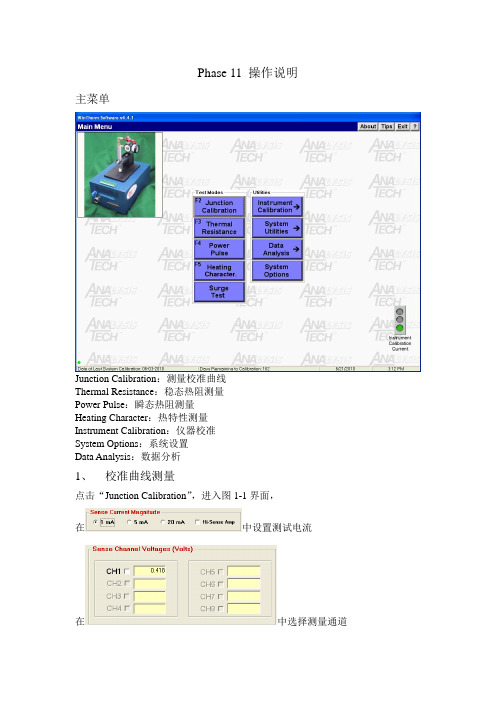
Phase 11 操作说明主菜单Junction Calibration:测量校准曲线Thermal Resistance:稳态热阻测量Power Pulse:瞬态热阻测量Heating Character:热特性测量Instrument Calibration:仪器校准System Options:系统设置Data Analysis:数据分析1、校准曲线测量点击“Junction Calibration”,进入图1-1界面,在中设置测试电流在中选择测量通道在中输入文件名称在中选择测量环境,一般默认油浴设置完后,点击,然后按下加热平台左侧红色按钮,然后仪器就会自动测量校准曲线,如图1-2,整个过程大概需要3个小时。
仪器在测量校准曲线过程中,会自动升温到125℃(可根据需要设定),然后降温,从125℃开始,每下降5℃测量一次,直至室温。
图1-1当温度降至室温后(约30℃),点击,然后点击,即可修正所测量的数据,再点击,即可得到校准曲线,如图1-3所示。
图1-2图1-32、稳态热阻测量点击Thermal Resistance进入图2-1所示界面Setup File Name:选择校准曲线Device Type:器件类型Device Calibration:选择通道(一般都为1)Data Storage Options:设置测量数据保存方式和内容图2-1点击Continue进入图2-2所示界面Heating Power Control:加热功率控制方式(默认为Manual)Active Sense Channels:敏感电流通道(一般为1)图2-2点击Continue进入图2-3界面点击Recal会在Offset Temperature中显示温度补偿,然后点击几次Repeat Recal,若没有问题,则在下面空白框中没有提示;若有提示,说明存在问题,通常为测试电路有问题或者校准曲线与测试电路不相符图2-3点击Begin Test进入测量界面,如图2-4所示,通过调节manual转轴来调节对器件所施加的功率,点击Graph可观察结温变化等曲线,如图2-5所示图2-4图2-53、瞬态热阻测量点击Power Pulse进入图3-1界面Setup File Name:选择校准曲线Device Type:器件类型Device Calibration:选择通道(一般都为1)Test Conditions:设置加热脉冲时间和加热电流Data Storage Options:设置测量数据保存方式和内容图3-1点击Continue进入图3-2界面在中设置测量内容(温升、热阻或结压变化)和测量通道在中设置测量次数和测量周期图3-2点击Continue进入图3-3界面点击Begin Test开始测量,第一次为试验,之后点击Verify为正式测量,测量完成后,点击Stop Test结束测量图3-34、热特性测量点击Heating Character进入图4-1界面Setup File Name:选择校准曲线Device Type:器件类型Device Calibration:选择通道(一般都为1)Test Conditions:设置加热功率Data Storage Options:设置测量数据保存方式和内容图4-1点击Continue进入图4-2界面点击Recal会在Offset Temperature中显示温度补偿,然后点击几次Repeat Recal,若没有问题,则在下面空白框中没有提示;若有提示,说明存在问题,通常为测试电路有问题或者校准曲线与测试电路不相符图4-2图4-3当所有变为时,测试会自动结束,如图4-4所示,点击Graphs可观察热特性曲线,如图4-5所示,双击任意曲线可使其放大,再双击返回。
功率MOSFET器件稳态热阻测试原理及影响因素

功率MOSFET器件稳态热阻测试原理及影响因素摘要:热阻值是评判功率MOSFET器件热性能优劣的重要参数,因此热阻测试至关重要。
通过对红外线扫描、液晶示温法、标准电学法3种热阻测试方法比较其优缺点,总结出标准电学法测试比较适合MOSFET热阻测试。
在此基础上依据热阻测试系统Phase11,阐述功率MOSFET热阻测试原理,并着重通过实例对标准电学法测试热阻的影响因素测试电流I m、校准系数K、参考结温T j以及测试夹具进行了具体分析,总结出减少热阻测试误差的方法,为热阻的精确测试以及器件测试标准的制定提供依据。
关键词:热阻测试原理;测试电流;校准系数;参考结温;测试夹具1热阻测试原理热阻是热平衡条件下沿器件热流通道上的温度差与产生温差的耗散功率之比,其单位为℃·W-1或K·W-1,公式为[10]:式中,T j表示结温,T c表示管壳温度,T a表示环境温度,P是耗散功率。
功率MOSFET是利用源-漏间续流二极管作为温敏元件进行测量的,如图1所示。
图1MOSFE结构图和电路符号整个热阻测试过程分成两部分,第一部分是将器件放在一个常温环境中并不断改变环境温度,同时保持器件和环境温度一致,在此过程中持续给续流二极管通过小电流,使半导体PN结结温变化T j与正向结电压变化V f呈良好的线性关系,用温度校准系数K来表示,满足关系式T j=K V f+T0,从而获得K系数值。
第二部分是在第一部分结束后,将被测器件放置到常温环境,给MOSFET整个器件施加功率PH,等待器件达到热平衡。
施加的功率引起结温变化,利用关系式T j=K V f+T0,其中T0为施加功率前的初始结温,K系数在第一部分已经获得,因此可以计算出达到热平衡之后的节温T j。
同时在加热功率结束时,可以通过热偶直接测得管壳的温度(环境温度),利用热阻的计算公式(1),可得器件稳态热阻值。
2热阻测试影响因素热阻的测试过程中需要确定好7个测试条件,之后才可以进行测试,这7个测试条件分别是:①测试电流I m;②温度校准系数K;③参考结温T j;④壳温T c(环境温度T a)的控制;⑤选取测试延迟时间T d;⑥功率加热时间T p;⑦脉冲方波信号选取。
ANALYSIS TECH 半导体微电子热阻导热系数测试仪

Analysis tech Phase 11 半导体热阻分析仪一、Analysis Tech Phase11 Phase10概述ANALYSISTECH半导体热分析仪Semiconductor Thermal Analyzer热阻测试仪中国MICOFORCE米力光CO供应,由美国Analysis Tech Inc公司的PHASE10 PHASE11 热阻测试仪电子封装器件,符合美军标和JEDEC标准. Analysis Tech Inc.成立于1983年,坐落于波士顿北部,是电子封装器件可靠性测试的国际设计,制造公司。
他的创始人是John W.Sofia,美国麻省理工的博士,并且是提出焊点可靠性,热阻分析和热导率理论的专家. 发表了很多关于焊点可靠性,热阻分析和热导率论文. Analysis Tech Inc.在美国有独的实验室提供技术支持.。
热阻分析仪Phase 11主要用于二极管、三极管、线性调压器、可控硅、LED、MOSFET、MESFET、IGBT、IC等分立功率器件的热阻测试和分析。
二、Analysis Tech Phase 11 Phase10工作原理及测试过程Phase 11采用油浴法测定热敏参数校正曲线。
在通以感应电流结还没有明显产生热量时,如果给定足够的时间,结温和壳温将达到热平衡,壳温非常接近结温。
将热电偶直接连接到器件表面采集数据时,油浴将充分保证器件的温度稳定并且使热电偶采集的温度等于感应结温。
在这个环节中,感应电流大小的选择是很重要的。
感应电流过大,会导致结温明显变化;感应电流过小,会导致正向压降值测量误差较大。
Phase 11 感应电流的可选范围是0.1mA~50mA,完全符合JEDEC标准。
在加热器件的过程中,Phase 11 采用了脉冲加热方式,如下图所示:加热电流和感应电流通过电子开关切换的方式轮流工作。
每加热15秒,测量1次热敏参数,即获得1个结温值,测量完之后继续加热,加热15秒,再次测量结温值,如此反复工作。
Thermal_TMA

该模式中,样品能在静态力、线性变化力或动态振荡力的作用下,并且在设定的温度程 序和气氛下进行测量。样品变形(应变)用膨胀或穿透实验记录,通过样品变形的特点来分 析材料的内在性质;动态实验用于测量粘弹性参数(DTMA)、检测热效应和分离重叠转变 (MTMATM)。
三点弯曲
在该弯曲形变中,样品被放置在两个石英刀口支架上,固定的静态力通过锲形的石英探 头垂直施加在样品的中部。材料的性质通过力和测量探头偏移来测定。因为没有夹具效 应,所以该模式是“纯”形变方式。它主要用来测定硬材料(如复合材料)在温度变化条件 下的弯曲性质。该夹具对Q400EM动态测量(DTMA)同样适用,这时用一个专门的低摩擦金属 支架代替石英刀口支架。
111
Strain
Strain (Force)
标准模式
T
Force Strain
Temperature (Time) 标准模式
F
T
Force (Time)
应力/应变模式(Q400EM)
在恒定的温度下,施加线性变化的应力或应变,测量对应的 应变或应力, 从而得到应力/应变图谱及相关的模量信息。另 外所计算出的模量作为应力、应变、温度或时间的函数来显示。
107
炉体 样品室
线性差动位移传感器
Q400 TMA样品测量系统的核心是精确的线性差
动位移传感器(LVDT)。它可根据位移变化产生
一个准确的与样品尺寸变化成比例的输出信号,
在很宽温度范围内(-150~1000℃)具有精确快速
的响应,十分有利于提高TMA测试数据结果的
重现性。LVDT位于炉子的下方,避免了温度效
拉伸
三点弯曲 110
TMA原理 / 操作模式
TMA是在设定的力、气氛、时间和温度的条件下测量材料的形变。施加力可采用压缩、弯曲或拉伸的形变方式(参见P109-110页)。 TMA测量材料固有的性质(如热膨胀系数、玻璃化转变温度、杨氏模量)等,以及工艺/产品性能参数(如软化点)。这些参数均具有 广泛的应用价值,它们既可通过Q400也可通过Q400EM获得。
《半导体物理》实验指导书(2022年版)
《半导体物理》实验指导书(2022年版)半导体物理实验指导书信息工程学院电子科学与技术教研室2022目录实验一:霍尔效应1实验二:四探针法测量半导体电阻率及薄层电阻6实验三:椭偏法测薄膜厚度和折射率9附录A:《RTS-8型双电测四探针测试仪用户手册》11附录B:《WJZ/WJZ-Ⅱ型多功能激光椭圆偏振仪使用手册》30I实验一霍尔效应一、实验目的1.了解霍尔器材对材料要求的知识;2.学习用“对称测量法”消除副效应的影响,测量试样的VH~IS曲线;3.学会确定试样的导电类型,载流子浓度以及电导率。
二、仪器设备QS-H型霍尔效应实验组合仪三、实验原理1.导体材料霍尔系数的确定由霍尔电压VH与磁感应强度B的关系,VHB和d,可计算出霍尔系数RHISB知,只要测出VH以及知道IS、dRHVHd(1)ISB2.导体材料导电类型的确定若实验中能测出IS、B的方向,就可判断VH的正负,决定霍尔系数的正负,从而判断出半导体的导电类型。
当RH0时,样品属N型(载流子为电子),反之则为P型(载流子为空穴)。
3.导体材料载流子浓度的确定由霍尔系数RH如果知道VH、IS、B,就可确定该材料的载流子浓度。
根据电导率与载流子浓度n以及迁移率之间的关系ne知,通过实验测出值即可求出1VHd,可得neISBIBnS(2)VHdeRH(3)4.霍尔组件对材料的要求根据上述可知,要得到大的霍尔电压,关键是要选择霍尔系数大(即迁移率高、电阻率亦较高)的材料。
因RH,就金属导体而言,和均很低,而不良导体虽高,但极小,因而上述两种材料的霍尔系数都很小,不能用来制造霍尔组件。
半导体高,适中,是制造霍尔元件较理想的材料,由于电子的迁移率比空穴的迁移率大,所以霍尔元件都采用N型材料,其次霍尔电压的大小与材料的厚度成反比,因此薄膜型的霍尔组件的输出电压较片状要高得多。
5.实验中的副效应及其消除方法在产生霍尔效应的同时,还存在一些与温度、电极与半导体接触处的接触电阻有关的效应,这些效应也会在霍尔元件的上下侧面产生电位差。
是德科技 B1500A半导体器件分析仪 使用说明书
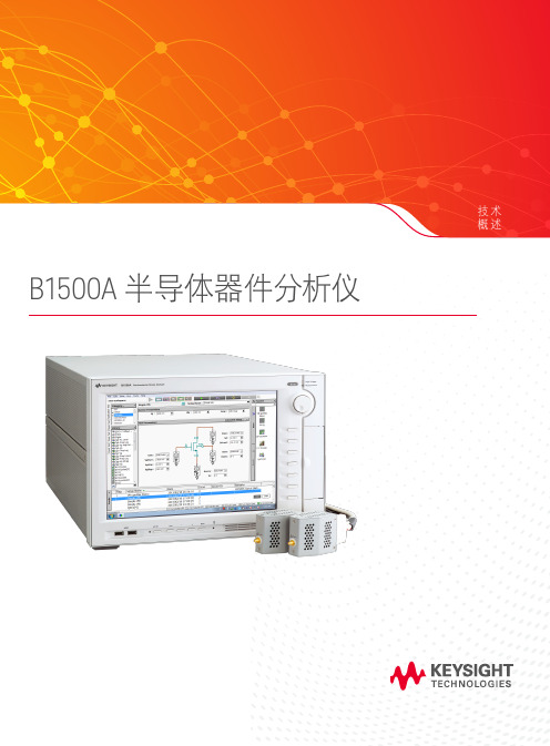
技术概述B1500A 半导体器件分析仪加快基本的电流-电压(IV )和电容-电压(CV )测量 以及业界领先的超快速 IV 器件表征脉冲 IV 测量B1500A 半导体器件分析仪将多种测量和分析功能整合到一台仪器中,可精确快速地进行器件表征。
它是目前唯一能够提供广泛的器件表征功能以及最出色测量可靠性和可重复性的多功能参数分析仪。
它能够执行从基本的电流-电压(IV )和电容-电压(CV )表征到快速、精准的脉冲 IV 测试的全方位测量。
此外,B1500A 的 10 槽模块化体系结构使您可以添加或升级测量模块,适应不断变化的测量需求。
综合解决方案满足您的 所有器件表征需求Keysight EasyEXPERT group+ 软件是 B1500A 自带的 GUI 界面软件,可在 B1500A 的嵌入式 Windows 10 平台上运行,支持高效和可重复的器件表征。
B1500A 拥有几百种即时可用的测量(应用测试),为测试执行和分析提供了直观和功能强大的操作环境。
它可以帮助工程师对器件、材料、半导体、有源/无源元器件或几乎任何其他类型的电子器件进行精确和快速的电子表征和 测试。
关键特性优势精密电压和电流测量(0.5 µV 和 0.1 fA 分辨率)–低电压和小电流的精确表征。
用于多频率(1 kHz 至 5 MHz )电容测量(CV 、C-f 和 C-t )与电流/电压(IV )测量 切换的高精度和低成本解决方案。
–无需重新连接电缆即可在 CV 和 IV 测量之间进行切换– 保持出色的小电流测量分辨率(使用 SCUU 时最小为 1 fA ,使用 ASU 时最小为 0.1 fA )– 为被测器件提供完整的 CV 补偿输出超快速 IV 测量,100 ns 脉冲和 5 ns 采样率–捕获传统测试仪器无法精确测量的超快速瞬态现象超过 300 种应用测试即时可用–缩短从学习仪器使用、进行测量到熟练操作仪器所需的时间包含示波器视图的曲线追踪仪模式–交互式地开发测试,并即时查看器件特征–无需使用任何其他设备便可对电流和电压脉冲进行验证(MCSMU 提供示波器视图)功能强大的数据分析和稳定可靠的数据管理–自动分析测量数据,无需使用外部 PC– 自动存储测量数据和测试条件,日后快速调用此信息让所有人都变成器件表征专家EasyEXPERT group+ 使器件 表征变得像 1、2、3 计算一样简单B1500A 的 EasyEXPERT group+ 软件包括 300 多种可以即时使用的应用测试,您只需简单的 3 步便可进行测量。
一种半导体热电性能测试仪[实用新型专利]
![一种半导体热电性能测试仪[实用新型专利]](https://img.taocdn.com/s3/m/df298f036294dd88d1d26be7.png)
专利名称:一种半导体热电性能测试仪专利类型:实用新型专利
发明人:蔡克峰,张爱霞,严冲,贺香荣申请号:CN200720067899.4
申请日:20070316
公开号:CN201016950Y
公开日:
20080206
专利内容由知识产权出版社提供
摘要:本实用新型涉及一种半导体热电性能测试仪,其特征在于包含提供中温环境的加热设备、氧化铝样品台、微热源、紫铜样品夹具、测试导线和热电偶与夹具及样品连接后与波发生器、数据采集仪及计算机连接。
本实用新型装置的优点在于:可测电导率、Seebeck系数及ZT值,装置简单实用、成本低、测温范围为室温至600℃,操作方便,测试功能多,测试精度高,重复性好。
申请人:同济大学
地址:200092 上海市杨浦区四平路1239号
国籍:CN
代理机构:上海光华专利事务所
代理人:余明伟
更多信息请下载全文后查看。
半绝缘砷化镓电阻率、霍尔系数和迁移率测试方法

半绝缘砷化镓电阻率、霍尔系数和迁移率测试方法半绝缘砷化镓(GaAs)晶体是一种非常重要的半导体材料,在电子器件和光电器件中得到广泛的应用。
为了实现高性能和可靠性,对半绝缘砷化镓晶体的电学性质需要进行精确的测试和分析。
其中,电阻率、霍尔系数和迁移率是三个重要的参数。
本篇文章就为大家详细介绍半绝缘砷化镓电阻率、霍尔系数和迁移率测试方法,其中包含相关参考内容。
一、半绝缘砷化镓电阻率测试方法半绝缘砷化镓电阻率测试方法一般采用四探针法,其原理是利用四根电极在半导体表面形成一个封闭区域,然后通过对两个相对的探针施加恒定电压,利用剩余两个探针测量电流。
然后根据欧姆定律计算半导体材料的电阻率。
以下是半绝缘砷化镓电阻率测试方法的参考内容:1. 测试仪器:(1)四探针测试仪(2)恒流源(3)数字万用表2. 测试步骤:(1)将半绝缘砷化镓样品放入测试夹具中,并夹紧。
(2)将四根探针依次插入样品表面,形成一个封闭区域。
(3)调节恒流源,使得两个相对的探针电压保持恒定。
(4)利用数字万用表测量另外两个探针的电流,并记录下来。
(5)根据欧姆定律计算半导体材料的电阻率。
二、半绝缘砷化镓霍尔系数测试方法半绝缘砷化镓霍尔系数测试方法是利用霍尔效应来测量半导体材料的电学性质。
该方法一般也采用四探针技术,但是在形成封闭区域的过程中,会施加一个垂直于半导体表面的磁场,因此电流在磁场作用下会发生偏转,并产生横向电场。
测量该横向电场与所施加磁场之间的关系,就可以计算出半导体材料的霍尔系数。
以下是半绝缘砷化镓霍尔系数测试方法的参考内容:1. 测试仪器:(1)霍尔效应测试仪(2)恒流源(3)数字电压表(4)强磁场制备设备2. 测试步骤:(1)将半绝缘砷化镓样品放入测试夹具中,并夹紧。
(2)将四根探针依次插入样品表面,并施加恒定电流。
(3)在样品表面施加一个垂直于表面的强磁场,调节强度。
(4)利用数字电压表测量两个相对的探针之间的横向电场大小。
半绝缘砷化镓电阻率、霍尔系数和迁移率测试方法

半绝缘砷化镓电阻率、霍尔系数和迁移率测试方法
半绝缘砷化镓是一种重要的半导体材料,其电学性能需要通过多种测试指标来评估。
以下是半绝缘砷化镓电阻率、霍尔系数和迁移率测试方法的相关参考内容。
1. 电阻率测试方法
半绝缘砷化镓的电阻率可以通过四探针法来测量。
具体步骤如下:
(1)将待测样品与四个导电探针接触,并将它们紧密压在一起,以确保低接触电阻。
(2)通过使用一个恒流源和一台毫伏表来测量电位差和电流。
将恒流源连接到两个探针,将毫伏表连接到另外两个探针。
(3)改变电流的大小,并记录电位差。
将电阻率计算为电位
差和电流的比值。
2. 霍尔系数测试方法
半绝缘砷化镓的霍尔系数可以采用霍尔效应来测量。
具体步骤如下:
(1)在待测样品上施加一个外部磁场,利用霍尔效应激发感
应电场。
(2)在感应电场的作用下,样品上出现电压信号。
将电压信号与外部磁场之间的关系称为霍尔系数。
(3)通过改变外部磁场的大小和方向来测量不同条件下的霍尔系数。
3. 迁移率测试方法
半绝缘砷化镓的迁移率可以通过霍尔系数和电导率来计算。
具体步骤如下:
(1)通过霍尔系数测试方法测量待测样品的霍尔系数。
(2)利用霍尔系数和电导率的关系,计算出样品的载流子浓度。
该计算是基于样品在电场下移动的动力学模型。
(3)通过电导率测量方法测量样品的电导率。
(4)将样品的载流子浓度和电导率代入迁移率计算公式中,即可得到迁移率的值。
以上就是半绝缘砷化镓电阻率、霍尔系数和迁移率测试方法的相关参考内容,希望对您有所帮助。
美国迈克罗斯公司 MPS11 分析熔点仪说明书
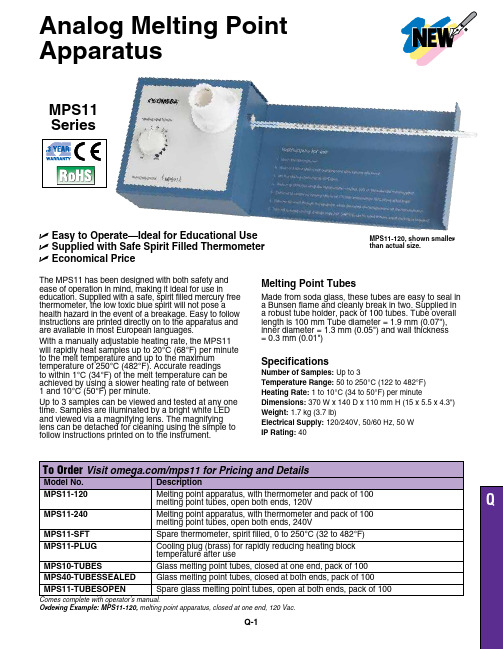
Analog Melting Point ApparatusQ-1Ordering Example: MPS11-120, melting point apparatus, closed at one end, 120 Vac.MPS11 SeriesU E asy to Operate—Ideal for Educational UseU S upplied with Safe Spirit Filled Thermometer U E conomical PriceThe MPS11 has been designed with both safety and ease of operation in mind, making it ideal for use in education. Supplied with a safe, spirit filled mercury free thermometer, the low toxic blue spirit will not pose a health hazard in the event of a breakage. Easy to follow instructions are printed directly on to the apparatus and are available in most European languages.With a manually adjustable heating rate, the MPS11 will rapidly heat samples up to 20°C (68°F) per minute to the melt temperature and up to the maximum temperature of 250°C (482°F). Accurate readings to within 1°C (34°F) of the melt temperature can be achieved by using a slower heating rate of between 1 and 10°C (50°F) per minute.Up to 3 samples can be viewed and tested at any one time. Samples are illuminated by a bright white LED and viewed via a magnifying lens. The magnifying lens can be detached for cleaning using the simple to follow instructions printed on to the instrument.Melting Point Tubes Made from soda glass, these tubes are easy to seal in a Bunsen flame and cleanly break in two. Supplied in a robust tube holder, pack of 100 tubes. Tube overall length is 100 mm Tube diameter = 1.9 mm (0.07"), inner diameter = 1.3 mm (0.05") and wall thickness = 0.3 mm (0.01")Specifications Number of Samples: Up to 3Temperature Range: 50 to 250°C (122 to 482°F)Heating Rate: 1 to 10°C (34 to 50°F) per minuteDimensions: 370 W x 140 D x 110 mm H (15 x 5.5 x 4.3")Weight: 1.7 kg (3.7 lb)Electrical Supply: 120/240V, 50/60 Hz, 50 W IP Rating: 40MPS11-120, shown smallerthan actual size.。
- 1、下载文档前请自行甄别文档内容的完整性,平台不提供额外的编辑、内容补充、找答案等附加服务。
- 2、"仅部分预览"的文档,不可在线预览部分如存在完整性等问题,可反馈申请退款(可完整预览的文档不适用该条件!)。
- 3、如文档侵犯您的权益,请联系客服反馈,我们会尽快为您处理(人工客服工作时间:9:00-18:30)。
Phase 11 Phase10半导体热阻分析仪米力光 MICOFORCE一、Analysis Tech Phase11 Phase10概述半导体热分析仪Semiconductor Thermal Analyzer热阻测试仪,由美国Analysis Tech Inc公司的PHASE10 PHASE11 热阻测试仪电子封装器件,符合美军标和JEDEC标准. Analysis Tech Inc.成立于1983年,坐落于波士顿北部,是电子封装器件可靠性测试的国际设计,制造公司。
他的创始人是John W.Sofia,美国麻省理工的博士,并且是提出焊点可靠性,热阻分析和热导率理论的专家. 发表了很多关于焊点可靠性,热阻分析和热导率论文. Analysis Tech Inc.在美国有独的实验室提供技术支持.。
热阻分析仪Phase 11主要用于二极管、三极管、线性调压器、可控硅、LED、MOSFET、MESFET、IGBT、IC等分立功率器件的热阻测试和分析。
二、Analysis Tech Phase 11 Phase10工作原理及测试过程Phase 11采用油浴法测定热敏参数校正曲线。
在通以感应电流结还没有明显产生热量时,如果给定足够的时间,结温和壳温将达到热平衡,壳温非常接近结温。
将热电偶直接连接到器件表面采集数据时,油浴将充分保证器件的温度稳定并且使热电偶采集的温度等于感应结温。
在这个环节中,感应电流大小的选择是很重要的。
感应电流过大,会导致结温明显变化;感应电流过小,会导致正向压降值测量误差较大。
Phase 11 感应电流的可选范围是0.1mA~50mA,完全符合JEDEC标准。
在加热器件的过程中,Phase 11 采用了脉冲加热方式,如下图所示:加热电流和感应电流通过电子开关切换的方式轮流工作。
每加热15秒,测量1次热敏参数,即获得1个结温值,测量完之后继续加热,加热15秒,再次测量结温值,如此反复工作。
在这个过程中,系统将每次测量到的结温值和前面7个结温值进行比较,如果连续8个结温值相同,系统会判定器件达到热平衡,并计算出稳态热阻值。
如果用户需要得到热阻热容曲线,只需要将电子开关锁定在测量端即可。
此时,因为没有了加热电流,器件开始降温,通过监测器件电压可以得到一条温度下降的曲线,进而通过一系列数学变换得到热阻热容曲线以及瞬态热阻抗曲线。
三、Analysis Tech Phase 11Phase10 技术指标Ø加热电流测量精度(低电流测量:0.2A,1A和2A测量)2A系统:±1mA,10A系统:±5mA,20A系统:±10mAØ加热电流测量精度(高电流测量:2A,10A和20A测量)2A系统:±4mA,10A系统:±20mA,20A系统:±40mAØ加热电压测量精度:±0.2%读数±0.025%量程Ø热电偶测量精度(T型):典型±0.1℃,最大±0.3℃Ø结温测量精度:典型±0.1℃Ø结温测量延迟时间:1usØ设备工作电压:220VAC,3A,50/60HzØ器件的最大供电电压:5V(选配Power Booster可以扩展到100V)Ø器件的最大供电电流:2A,10A,20A(选配Power Booster可以扩展到1000A)Ø结温的感应电流:1mA,5mA,10mA,20mA,50mA,0.1~50mA可设定四、附件介绍1、Nuova校准浴锅用来得到节电压和结温的函数关系即K值。
产品特点:1)由集成在热阻分析仪中的模块直接进行温度控制2)使用有陶瓷镀层的磁力搅拌器3)带有冷却风扇的坚固底盘能够控制升温速率并保证安全性4)有盖的四升不锈钢水浴锅5)悬挂结构支持部件被校准6)四升绝缘良好的导热矿物油,对环境无害并能重复使用2、EVN-12静止空气测试箱EVN-12是用于在标准化的静止空气环境中测试元件。
自然对流条件下的热阻测量会对实验室里的不期望的空气流动非常敏感。
这套静止空气测试箱可以排除这种潜在的产生测试错误的因素。
3、风洞相对于静止空气测试箱,伺服控制风洞提供了一个强制对流、均匀一致的测试环境。
在测试对气流比较敏感的器件时,我们能够更加准确地测量出器件在不同风速下的热阻。
4、Rjc测试夹具(风冷型)风冷型Rjc测试夹具是一个高性能的风冷型热沉,可以很方便地固定被测器件,是测量JEDEC标准定义Rjc的理想夹具。
Rjc测试夹具采用了一种特殊的装置可以准确的测量壳温。
5、Rjc测试夹具(水冷型)水冷型Rjc测试夹具需要配合循环冷水机使用,具有散热迅速的特点,通常用来测试IGBT和MOSFET等功率较大的器件。
6、Rjb测试夹具完全按照JEDEC JESD51-8的要求设计,用来测试结到电路板的热阻。
7、LED高压放大器当被测LED的正向压降高于5V,可以选择LED高压放大器,提供28V的测试电压。
8、功率放大器提供高达200A,400A和1000A的加热电流。
9、热阻分析仪校准仪溯源到NIST,可以用于热阻分析仪的故障诊断,建议每半年对热阻分析仪做一次校准。
10、热电偶校准仪溯源到NIST,用于对热电偶接口进行校准。
五、Analysis Tech Phase 11主要特色Ø所有测试数据、图像全屏显示Ø高速数据采集和分析,能对各种类型器件进行测试Ø能够输出常规的数据和文件类型,能将设置参数和数据存储在硬盘上Ø能对操作人员的错误和测试数据的有效性进行连续监测Ø四线制测试方法排除测试导线电阻的影响Ø兼容IEEE488和RS-232C通讯方式,测试方法遵循MIL&JEDEC标准Ø根据电流、功率或ΔTj对器件的功率进行自动控制,用户选择热平衡的监测方法Ø对附属设备进行自动控制,对集成电路和多芯片模块有多结探测能力Ø三个内部参考热电偶,能通过红外线对器件表面的温度进行测试Ø有标准和常规的测试夹具,设备校准方便Analysis Tech Thermal Analyzers measure semiconductor junction temperatures using the electric method of junction temperature measurement for testing all types of semiconductor devices. This capability is the foundation of numerous test methods including: thermal resistance, transient thermal impedance, die attach screening and functional power cycling. The convenient flexibility of the analyzer also facilitates interconnected control of other laboratory test equipment.Semiconductor Thermal Analyzers perform thermal measurements on all types of packaged semiconductor devices including diodes, LEDs, bipolar transistors, MOSFETs, functional analog/digital integrated circuits, ACSICS, IGBTs, SCRs, TRIACs, and thermal-test-dies. All products offered conform to applicable JEDEC and MIL Standards.Using the electrical method of junction temperature measurement, Analysis Tech Thermal Analyzers accurately measure component thermal parameters - essential for design and implementation of thermally reliable electronics. In addition to equipment sales, Analysis Tech offers Component Test Services for thermal characterization of semiconductor devices at our factory test-laboratory.This type of test equipment is alternately known as: semiconductor thermal resistance testers, semiconductor thermal impedance testers, component thermal resistance testers, component thermal impedance testers, die attach testers, die attachment testers.The Analysis Tech Thermal Analyzer Phase 11 provides comprehensive automated control of semiconductor thermal measurements for production and development testing with powerful features such as:All Test Modes:▪Test capabilities for all device-types: diodes, LEDs, bipolars, MOSFETs, IGBTs, functional ICs, thryistors, thermal test dies▪Automated high speed data collection, reduction, and analysis▪Compatible with all 750E Mil Stds and JEDEC 51 Series methods▪Data plots for all test parameters in all tests modes▪Simple, automated "in-lab" instrument-calibration procedures ▪Various text and graphics file formats for convenient exporting ▪Continuous intelligent monitoring for errors and data validity▪Kelvin (4-wire) connections to eliminate test cable resistances effects▪Compatibility with USB, IEEE 488, and RS-232C communications▪10/100 Ethernet NIC interface▪Test methods compatible with MIL & JEDEC test standards▪Selection of automatic power-control by current, wattage, and ΔTj▪Standard and custom test fixturing available ▪Windows XP Pro operating systemSteady State Thermal Resistance Mode:▪Multi-junction temperature sensing capability for ICs & multi-die devices▪User-selectable thermal equilibrium criteria▪Batch-mode for determining power level and air flow effects▪Control of accessory laboratory equipment for integrated testing ▪Infrared case temperature measurement capability▪Capability for automatically switching the device under testDie Attach or Power Pulse Mode:▪Pass/Fail or bin sorting based on die-attach quality▪Serialized part testing▪Data plots of all parameters including die-attach histogram▪Extended-life testing with interspersed die-attach testing▪Interface for mechanized device handlers▪Batch mode die-attachment production testing multi-chip modulesHeating Characterization / Transient Thermal Impedance Mode:▪Heating and cooling curve time-resolution: 1 microsecond▪Heating and cooling curve span: 1 microsecond - 10,000 seconds▪Heating and cooling curve points-per-decade plotted: 15▪Utilizes time-constant-spectrum and structure function analyses ▪Optimized compact dynamic RC models with 2-8 discrete stagesMultiple Sense-Junction ChannelsUp to eight junction temperatures can be simultaneously sensed for testing devices with multiple junctionsand for characterizing multi-chip packages or modules. In multiple-die packages, the die-to-die heating (thermal cross-coupling) must be measured to accurately characterize these type of packages. For testing functional integrated circuits (ICs), multiple sense junctions offer validation of the junction temperature (Tj) readings in instances where some of the Tj sense connections are subject to the spurious electrical effectsof other portions of the IC circuitry. When testing hybrids and large-die ICs, multiple sense junctions canreveal temperature distributions that occur when substantial temperature variations exist within the test device. Multiple sense channel applications include:▪Multi-die devices where multiple heat sources may exist▪Thermal cross-coupling associated with multi-chip devices▪Larger devices which may exhibit substantial temperaturegradients during normal powered operationMultiple sense channels also permit the calibration of up to 8 sense junctions simultaneously for faster calibration through-put.Batch Mode and Bin Sorting for Power Pulse TestingAccurate and rapid screening of device thermal characteristics can dramatically enhance production-device reliability. Die Attachment testing provides an excellent gauge of the chip attachment-quality in terms of the device impedance. The Phase 11 Thermal Analyzer provides programmable relay drivers for controlling external devices during Power Pulse Testing. These drivers offer the following capabilities:▪switching between test points in hybrid circuit test fixtures for multiple sequenced tests▪manual or automatic handler controls bin sorting based on die attachment test resultsThe test switching capability of the Thermal Analyzer allows one test fixture to carry all the test connections or test-point probes for a batch of tests required for testing complex hybrids. Thus all significant die attachments on a hybrid can be tested with one insertion and one test initiation.Bin sorting is utilized in die attach testing to rapidly sort devices based on die-attachment quality. The bin sorting control can be used with manual insertion testing or with automatic component transfer systemswhich would insert devices to be tested into test fixtures and subsequently eject the tested device into oneof up to eight bins. (see Die Attach Testing in Production Environments)Accessory Equipment Control PortsFrequently, device thermal performance must be evaluated over a range of external conditions. Such conditions might include cooling air flow, ambient operating temperature, coolant flow rate, or the heating supply voltage. The Thermal analyzer can control accessory test equipment via USB, IEEE, or serial communication toachieve integrated batch testing under a wide range of external conditions. The Analysis Tech accessoryBatch Switching Module provides a convenient means to switch the device-under-test so that many devices can be tested sequentially in batch mode.The simple setup and control procedures of the Thermal Analyzers allow the test engineer to initiate up to 200 tests in batch mode. Tests are successively executed automatically: as a test reaches completion,the external condition is incremented and the test cycle repeated until the batch of tests is completed.Once these batch tests have begun, data reporting and accessory equipment control are automatically coordinated.The Analysis Tech Phase 11 Thermal Analyzer performs a variety of semiconductor thermal tests controlled from a powerful Windows based operating program and continuous-display front panel meters.The convenient user-interface facilitates complete thermal characterization for any type of semiconductor device or package type according to Mil Std 750E and JEDEC 51 Series methods..The Phase 11 Thermal Analyzer can be easily configured to perform tests on a wide range of device types including digital or analog functional integrated circuits, thermal test dice, bipolar transistors, diodes, MOSFETS, IGBTS, thyristors, and ASICs. During testing, comprehensive graphic data-displays offer superb detail on all test data, thus promoting confidence and understanding of the test results.All semiconductor junction temperatures are accurately measured using the electrical method.Parts can be tested by simply selecting the part-specific Setup File which includes all of the necessarytest parameters for the desired test method. Test data is stored on the PC hard disk including final numerical data such as thermal resistance, power levels, reference temperatures, as well as data plots, and pass/fail evaluations. Text and graphic files can be stored in various file formats as needed forexport to other Windows applications. A network connection (NIC) is provided so that test data canbe archived to your LAN.The Analysis Tech Phase 11 Thermal Analyzer provides manual or automatic heating power control.Three thermocouples reference temperatures ports are provided for measurement of external package temperatures such case, lead, etc. Thermal equilibrium is automatically detected based on a varietyof user-selectable criteria. Real-time data plots and tabular displays are readily accessible as testing proceeds. Batch Mode testing offers automatic sequencing of tests with alternate power levels,different test-devices, or varied environmental conditions such as ambient air flow speed or temperature.The Phase 10/11 Calibrator offers a powerful and convenient method for annual or biannual instrument calibration without the expense and "down-time" associated with typical "cal-lab" procedures. Thermocouple calibration is comprehensive and automated with the Phase 10/11 Tc Calibrator.Die attachment bin-sorting offers an efficient means to sort devices according to the thermal quality of the die attachment. Power Pulse Batch Mode performs a rapid sequence of die-attachment tests on up toeight separate devices. With this capability, multiple active devices on a multi-chip module can be tested for die-attachment with one insertion of the device-under-test.The Analysis Tech Phase 11 Thermal Analyzer uses an external DC supply for the heating power source, coupled to the Thermal Analyzer via a rear-panel connection. In all test modes, the external supply is controlled by the Thermal Analyzer to provide the desired heating-power level. The external power supply is not included with the Thermal Analyzer but can be purchased as part of the Discount Accessory Package or separately.The maximum power handling capacity of the Analysis Tech Phase 11 Thermal Analyzer is 100W, 500W, and 1000W for the 2A, 10A, and 20 A analyzers, respectively. The Power Booster accessory offers heating currents up to 1000 amps and heating power levels up to 6000 watts.All Thermal Analyzer sales include free training at our factory-based test lab facilities.。
