field guide to interferometric optical testing
光纤传感白光干涉
光纤白光干涉摘要光纤干涉型传感器是光纤传感器中的一个重要分支,而白光干涉测量技术是一种被广泛应用的光学干涉测量技术。
白光干涉测量技术应用于光纤干涉型传感器,能够测量光纤干涉仪的绝对光程差,且动态测量范围大,测量分辨率高。
本论文分别阐述了扫描白光干涉测量技术和光谱域光纤白光干涉测量技术的原理与研究现状,分析和总结了不同的光纤白光干涉测量的结构和特点。
关键词:光纤传感器;光纤干涉仪;白光干涉测量术;AbstractFiber optic interferometric sensor is an important branch of the fiber optic sensor. White-light interferometry is a widely used technique of the optical interferometry. The white-light interferometry, which is applied to fiber optic interferometric sensor can measure the absolute optical path difference (OPD) and possess the abilities to provide large dynamic measurement range and high measurement resolution.In this dissertation, the principles and research status of scanning white-light interferometry and spectral-domain optical fiber white-light interferometry are described respectively. The structures and characteristics of different optical fiber white-light interferometry are analyzed and summarized.Keywords:Fiber optic sensor;fiber optic interferometer; white-light interferometry;1、绪论光纤传感技术是20世纪70 年代末新兴的一项技术,近年来,光纤传感技术在当代科技领域及实际应用中占有十分重要的地位。
外差双频干涉法

外差双频干涉法詹姆斯·C。
wyant光学科学中心亚利桑那大学亚利桑那州图森85721摘要:双频相移干涉测量对于单频干涉测量来讲,对测量范围的扩展称得上一个强大的技术。
本文论述了三种扩展相移干涉测量的动态范围的方法,且其精确度不小于单个短波长测量。
这些技术起源于对干涉基本原理的运用和不同技术之间的权衡进行的讨论。
简介:干涉测量是一个非常强大的技术,它提供了从埃到百万英里的测量能力。
而干涉的基本原理已经被发现了超过100年,现代电子、计算机以及软件的加入使干涉成为解决众多计量问题的非常有用的技术。
随着相移干涉技术的加入,干涉测量数据可以传送到计算机内存并且实现复杂的数据分析。
光学干涉一个最大的优点也是其一个最大的不足之处。
短波长的光在单频干涉测量的灵敏度非常高,同样,由于光的波长短,测量的动态范围是有限的,除非附加有用信息。
在单频干涉测量光的相位(即干涉图样的相位)中,波长等于距离的二倍。
因此,光程差δ给出了)(δλ+n 的相同干涉测量,其中n 是一个整数。
在距离或高度的测量中确定整数n 的一个好方法是使用白光扫描干涉。
如果干涉仪使用白色光源,则只有当干涉的两个路径是相等时才获得最佳对比度干涉条纹。
因此,如果干涉样品臂的干涉路径的长度是多种多样的,整个样品的距离或高度变化可由条纹对比度是最大的镜子或样品位置确定。
在这种测量中没有高度的含糊之处,并且因为在干涉适当调节时,样品是获得最大的条纹对比度的关键,同样也是在表面微结构测量中的关键。
这种类型的扫描干涉仪测量的主要缺点是,只有一个单一的距离或表面高度同时被测和大量的测量和计算,需要确定一个大范围的距离或表面高度值。
此外,如果仅在扫描位置上寻找最大的条纹对比度决定高度信息,其测量精度则低于由观察干涉条纹的相位获得的高度信息的精度。
第二个解决在波长测量中确定当前整数的优秀的方案为,在距离测量中对多个波长进行测量和比较不同波长的测量结果,以确定实际的距离。
优美斯(Optimax Systems)的相位平移干扰光学测量方法白皮书说明书

The Effect Of Phase Distortion On InterferometricMeasurements Of Thin Film Coated Optical SurfacesJon Watson, Daniel SavageOptimax Systems, 6367 Dean Parkway, Ontario, NY USA*********************©Copyright Optimax Systems, Inc. 2010This paper discusses difficulty in accurately interpreting surface form data from a phase shifting interferometer measurement of a thin film interference coated surfaces.PHASE-SHIFTING INTERFEROMETRYPhase-shifting interferometry is a metrology tool widely used in optical manufacturing to determine form errors of an optical surface. The surface under test generates a reflected wavefront that interferes with the reference wavefront produced by the interferometer 1. A phase-shifting interferometer modulates phase by slightly moving the reference wavefront with respect to the reflected test wavefront 2 . The phase information collected is converted into the height data which comprises the surface under test3.Visibility of fringes in an interferometer is a function of intensity mismatch between the test and reference beams. Most commercially available interferometers are designed to optimize fringe contrast based on a 4% reflected beam intensity. If the surface under test is coated for minimum reflection near or at the test wavelength of the interferometer, the visibility of the fringe pattern can be too low to accurately measure.OPTICAL THIN-FILM INTERFERENCE COATINGSOptical thin-film interference coatings are structures composed of one or more thin layers (typically multiples of a quarter-wave optical thickness) of materials deposited on the surface of an optical substrate.The goal of interference coatings is to create a multilayer film structure where interference effects within the structure achieve a desired percent intensity transmission or reflection over a given wavelength range.The purpose of the coating defines the design of the multilayer structure. Basic design variables include:• Number of layers• Thickness of each layer• Material of each layerThe most common types of multilayer films are high reflector (HR) and anti-reflection (AR) coatings. HR coatings function by constructively interfering reflected light, while AR coatings function by destructively interfering reflected light. These coatings are designed to operate over a specific wavelength range distributed around a particular design wavelength.To produce the desired interference effects, thin-film structures are designed to modulate the phase of the reflected or transmitted wavefront. The nature of the interference effect depends precisely on the thickness of each layer in the coating as well as the refractive index of each layer. If the thickness and index of each layer is uniform across the coated surface, the reflected wavefront will have a constant phase offset across the surface. However, if layer thicknesses or index vary across the coated surface, then the phase of thereflected wavefront will also vary. Depending on the design of the coating and the severity of the thickness or index non-uniformity, the distortion of the phase of the reflected wavefront can be severe. 4Layer thickness non-uniformity is inherent in the coating process and is exaggerated by increasing radius of curvature of the coated surface.5 All industry-standard directed source deposition processes (thermal evaporation, sputtering, etc) result in some degree of layer thickness non-uniformity.5 Even processes developed to minimize layer non-uniformity, such as those used at Optimax, will still result in slight layer non-uniformity (within design tolerance).TESTING COATED OPTICS INTERFEROMETRICALLYPhase-shifting interferometers use phase information to determine the height map of the surface under test. However, surfaces coated with a thin-film interference coating can have severe phase distortion in the reflected wavefront due to slight layer thickness non-uniformities and refractive index inhomogeneity. Therefore, the measured irregularity of a coated surface measured on a phase shifting interferometer at a wavelength other than the design wavelength, may not represent the actual irregularity of the surface. Even using a phase shifting interferometer at the coating design wavelength does not guarantee accurate surface irregularity measurements. If a coating has very low reflectance over any given wavelength range (such as in the case of an AR coating), the phase shift on reflection with wavelength will vary significantly in that range.7 Figure 1 shows an example of how the phase can vary with coating thickness variations.Figure 1In this particular case, if a point at the lens edge has the nominal coating thickness and the coating at lens center is 2% thicker, expect ~38° phase difference in the measurement (~0.1 waves). This will erroneous be seen as height by the interferometer, despite the actual height change in this case being less than 7nm (~0.01 waves). Also, depending on coating design, low fringe visibility may inhibit measurements.There is an extreme method to determine the irregularity of a thin-film interference coated surface by flash coating it with a bare metal mirror coating. A metal mirror coating is not a thin-film interference coating, and the surface of the mirror represents the true surface, This relatively expensive process requires extra time, handling, and potential damage during the metal coating chemical strip process.CONCLUSIONS•There can be practical limitations to getting accurate surface form data on coated optical surfaces due to issues with phase distortion and fringe visibility.•The issues are a function of thin film coating design particulars and the actual deposition processes.1 R.E. Fischer, B. Tadic-Galeb, P. Yoder, Optical System Design, Pg 340, McGraw Hill, New York City, 20082 H.H. Karow, Fabrication Methods For Precision Optics, Pg 656, John Wiley & Sons, New York City, 19933 MetroPro Reference Guide OMP-0347J, Page 7-1, Zygo Corporation, Middlefield, Connecticut, 20044 H.A. Macleod, Thin Film Optical Filters, Chapter 11: Layer uniformity and thickness monitoring, The Institute of Physics Publishing, 2001.5 R.E. Fischer, B. Tadic-Galeb, P. Yoder, Optical System Design, Pg 581, McGraw Hill, New York City, 2008。
光学耦合器的原理
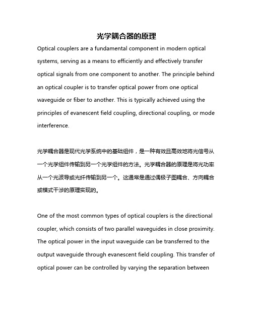
光学耦合器的原理Optical couplers are a fundamental component in modern optical systems, serving as a means to efficiently and effectively transfer optical signals from one component to another. The principle behind an optical coupler is to transfer optical power from one optical waveguide or fiber to another. This is typically achieved using the principles of evanescent field coupling, directional coupling, or mode interference.光学耦合器是现代光学系统中的基础组件,是一种有效且高效地将光信号从一个光学组件传输到另一个光学组件的方法。
光学耦合器的原理是将光功率从一个光波导或光纤传输到另一个。
这通常是通过偶极子图耦合、方向耦合或模式干涉的原理实现的。
One of the most common types of optical couplers is the directional coupler, which consists of two parallel waveguides in close proximity. The optical power in the input waveguide can be transferred to the output waveguide through evanescent field coupling. This transfer of optical power can be controlled by varying the separation betweenthe waveguides and the refractive index of the material, allowing for precise control over the coupling ratio.最常见的光学耦合器之一是定向耦合器,它由两个相距很近的平行波导组成。
光学词汇

absolute optical frequency measurement 绝对光频测量; 绝对光频测absorpting loss in optical thin-film 光学薄膜的吸收损耗console optical-display plotter 控制台光显示绘图仪continuous variable optical attenuator 连续可变光衰减器continuous-wave optical ranging system 连续波光学测距系统convex optical tool 光学玻璃凸面磨coronal optical polarization 日冕光学偏振coupled optical resonators 耦合光谐振腔cross-coupling optical beam 交叉耦合光束crown optical glass 冕牌光学玻璃curved holographic optical element 曲面全息光学元件CW optical maser action 连续激光振荡dielectric optical waveguide 介质光波导diffused optical waveguide 扩散光波导digital optical tracking set 数字光学跟踪装置disappearing-filament optical pyrometer 隐丝光学高温计discrete bit optical memory 打点式光存储器; 逐位式光存储器dislocation of optical range-finder 光学测距机的失调dispersive optical system 色散光学系统double resonant optical parameter oscillator 双共振参量振荡器doubly clad optical fibre 双包层光学纤维duct optical cable 管道光缆elasto-optical coefficient 弹光系数electrical isolation optical memory 电隔离光存储器electrical optical converter 电光变换器electrical to optical converter 电光转换器electro-optical beamsplitter 电光分光镜electro-optical converter 电光变换器electro-optical crystal 电光晶体electro-optical detector 电光检测器electro-optical diffraction modulator 电光衍射调制器electro-optical digital deflector 电光数字式偏转器electro-optical guided bomb 电子光学制导炸弹electro-optical hot gas pyrometer 电光热气高温计electro-optical image tube 光电移像管electro-optical light intensity modulator 电光光密度调制器electro-optical light-detecting apparatus 电光测光器; 电光光探测器electro-optical modulator 电光调制器electro-optical multiframe camera 光电多幅照相机electro-optical property 电光性质electro-optical sensor 电光传感器electro-optical shutter 电光快门electro-optical switch 电光开关electro-optical system 光电系统electro-optical tracker system 光电跟踪系统electro-optical tube 光电管electro-optically tuned laser 电光可调激光器electron optical prism 电子光学棱镜electron-optical aberration 电子光学象差electron-optical image intensifier 电光像增强器electron-optical system 电子光学系统electronic optical comparator 光电比较仪electronically tunable optical filter 电子可调谐光学滤波器equivalent optical thickness of thin film 薄膜等效厚度erasable optical disk 可擦光盘erbium-doped optical fiber amplifier 掺铒光纤放大器etalon optical power 标准光强度external optical density 外光密度fast refractive infrared optical system 快速折射红外光学系统fibre optical device 纤维光学装置fibre optical screen 纤维光学屏幕fibre optically coupled cascaded image intensifier 光纤耦合级联式图像增强器fibre-optical cable 纤维光缆field optical collimator system 场致光学准直仪系统filling material for optical fiber cable 光缆缆芯填充料film optical modulator 薄膜光调制器film optical multiplexer 薄膜光复用器film optical sensing device 胶片光学传感器film optical switch 薄膜光开关film optical waveguide 薄膜光波导flat optical cable 扁平光缆flat optical tool 光学玻璃平面研磨盘flint optical glass 火石光学玻璃fluorozirconate type optical fiber 氟化锆基光纤focusing optical fiber 聚焦光纤; 聚焦光纤Fourier optical imaging system 傅里叶光学成像系统frequency discriminating optical chopper 鉴频光学限制器gallium-arsenide optical filter 砷化镓滤光片gas-discharge optical maser 气体放电光学微波激射; 气体光学脉泽geometric-optical aberration 几何光学像差geometrical-optical approximation 几何光学近似germanium-doped optical fiber 掺锗光学纤维giant optical pulsation 巨光脉动; 巨光脉动giant optical pulse 巨光脉冲; 巨光脉冲glass optical fiber 玻璃光纤graded index optical waveguide 渐变折射率光波导graded-index optical fiber 渐变折射率光学纤维graphical design of optical system 光学系统图解设计ground-based optical receiver 地面光学接收机; 地面光学接收器gyro erected optical navigation 陀螺光学导航heat treatment of optical crystal 光学晶体热处理heteroepitaxial optical waveguide 异质外延光波导high birefringence optical fiber 高双折射光纤high performance optical cable connector 高性能光缆连接器high precision optical plate 高精度光学平板high repetition rate optical pulse 高重复率光脉冲high speed optical switch 高速光学开关high speed-optical switch 高速开关high strength optical fiber 高强度光纤high temperature optical fiber sensor 高温光纤传感器high-resolution optical mask 高分辨率光学掩膜high-resolution optical memory 高分辨率光存储器holographic optical elements (HOE) 全息光学元件homogeneous optical waveguide 均匀光学波导; 均匀光学波导hybrid optical cable connector 混合式光缆连接器hybrid optical fiber sensor 混合式光纤传感器image dividing optical system 光学分像系统image optical reconstruction 图像光学恢复image spliting optical system 影像分光系统image-dividing relay optical system 分像转向光学系统incoherent optical arrangement 非相干光学装置incoherent optical converter 非相干光转换器incoherent optical information processing 非相干光信息处理incoherent optical radar 非相干光学雷达inelastic optical scattering 非弹性光散射infrared optical fiber 红外光纤infrared optical material 红外光学材料infrared optical measuring system 红外光学测量系统inserting optical cable connector 插入光缆连接器inspection of optical crystal 光学晶体检验integrated optical bolometer for radiation 集成光学辐射热测量计integrated optical circuit 集成光路; 集成光学电路integrated optical spectrum analyzer 集成光谱分析器integrated optical switch 集成光学开关integrated optical waveguide coupler 集成光学波导耦合器intercept ground-based optical recorder 监视地面光学记录仪interferometric optical fiber acoustic sensor 干涉型声光纤声传感器internal optical density 内光密度; 内光学密度internal optical parametric oscillation 内光学参量振荡internal optical parametric oscillator 内光学参量振荡器Kerr electro optical law 克尔电光定律lamp bulb for optical pyrometer 光学高温计用灯泡large aperture optical system 大孔径光径系统large optical cavity laser 大光腔激光器large optical reflector 大型反光镜large optical-cavity diode 大光腔二极管large optical-cavity laser diode 大光腔激光二极管laser damage of optical coatings 光学镀层激光损伤laser optical bench 激光器光具座laser optical demonstration instrument 激光光学演示仪leaf optical system 薄片光学系统lens optical length 镜头光学长度; 镜头光学长度light splitting optical system 分束光学系统light-splitting optical system 分光光学系统LiNbO 3 optical parametric oscillator 掺镁铌酸锂光参量振荡器linear electro-optical effect 线性电光效应liquid-core optical fibre 液芯光纤loaded diffused optical waveguide 加载扩散光波导long haul optical link 长距离光线路long wavelength pass optical filter 长波长光通滤波器longitudinal fundamental optical frequency 纵向光学基频率lunar optical altimeter 登月用光学测高计magnet-optical memory system 磁光存储系统magnetic optical disk disk 磁光盘magnetic optical-character reader 磁光字符阅读器magnetid-optical devices 磁光器件magneto optical disk 磁光盘magneto optical disk editor 磁光盘编辑器magneto optical driver 磁光盘驱动器magneto optical semiconductor laser 磁光半导体激光器magneto-optical modulator 磁光调制器magneto-optical phenomenon 磁光现象magneto-optical shutter 磁光开关mass optical memory 大容量光存储器mechanical optical comparator 机械光学比较仪mechanical optical switch 机械光开关mechanically-driven optical reflector 机械传动光反射器medical optical instrument 医疗光学仪器; 医用光学仪器metal-clad optical waveguide 金属包层光学波导meteorological optical range 气象光学视距; 气象能见度military optical instrument 军用光学仪器; 军用光学仪器mirror-optical system 反射镜光学系统mobile optical tracking unit (MOTU) 机动光学跟踪装置mode of optical cavity 光学共振腔模; 共振腔的振荡模modular opticaltest instrument for fiber 模块化光纤光学测试仪monomode optical fiber 单模光纤monomode optical waveguide 单模光波导monopulse optical receiver 单脉冲光接收器multi-fiber optical cable 多芯电缆multi-fiber optical submarine cable 多芯海底光缆multichannel optical analyzer 多通道光学分析器multichannel optical cable stranding machine 多路光缆绞制机multicomponent glass optical fiber 多组分玻璃光纤multifont optical arena 多字体识别器multimode optical cable 多模光缆multimode optical fiber 多模光导纤维; 多模光纤multimode optical fiber hydrophone 多模光纤水听器multireflector optical resonator 多反射镜光学共振器naval gun optical director 舰炮光学指挥仪non-coherent Fourier-optical imaging system 非相干傅里叶光学成像系统non-coherent optical carrier 非相干光学载波non-coherent optical computer 不相干光学计算机non-coherent optical detector 非相干光检测器; 非相干光探测器non-coherent optical processing system 非相干光处理系统non-erasable optical disk 不可擦光盘non-metallic type optical cable 非金属型光缆non-optical propagation 封闭通道传播non-polar optical scattering 非偏振光散射nondestructive readout optical memory 无损读出光存储器nonlinear optical coefficient 非线性光学系数nonlinear optical crystal 非线性光学晶体nonlinear optical effect 非线性光学效应nonlinear optical phenomena 非线性光学现象nonlinear optical processing 非线性光学处理nonlinear optical response 非线性光学响应nonlinear optical susceptibility 非线性光极化率numerical designation of optical glass 光学玻璃标号offset optical square 偏距光学直角头omnidirectional optical scanner 全向光学扫描器on-board optical system 机载光学系统optical 光学的; 旋光; 视力的optical aberration 光学像差; 像差; 象差optical absorption 光的吸收; 光学吸收optical absorption band 光吸收带optical absorption edge 光吸收限; 光学吸收限optical access coupler 光学取数耦合器optical accessory 光学附件optical achromatism 可见光消色差性optical acquisition 光学捕获optical acquisition equipment 激光捕获装置optical active phonon 光激活声子optical active substance 光活性物质optical activity 光学活性; 旋光度; 旋光性optical activity of oil 石油的旋光性optical adaptive technique 光自适应技术; 光学自适应技术optical admittance 光学导纳optical agnosia 视觉性认识不能optical aid 光学辅助工具optical air mass 光学空气质量; 大气光学质量optical alignment 光学调准; 光学装校; 光学准直optical alignment equipment 光学校准设备optical alignment unit 光学校准设备optical altimeter 光学测高计; 光学高度计optical ammeter 光学安培计; 光学电流计optical amplification 光放大optical amplifier 光放大器; 光学放大器optical amplifier bandwidth 光放大器带宽optical amplitude modulator 光调幅器; 光振幅调制器optical analog 光学模拟optical analog device 光学模拟装置optical analog memory 光模拟存储器optical analog transform technique 光学模拟变换技术optical analogue computer 光学模拟计算机optical analyser 光学检偏振器optical analysis 光学分析optical analyzer 光学分析器; 光学检偏镜optical anemometer 光学风速计optical angle gauge 光学测角仪optical angular motion sensor 光学角运动传感器optical anisotropy 光学的各向异性; 光学各向同性; 光学异向性optical anomaly 光反常; 光性异常; 光学反常; 光学性反常optical antenna 光波段天线; 光学天线optical antenna angle 光学天线张角optical antenna aperture 光学天线孔径optical antenna gain 光学天线增益optical antipode 光对映体; 旋光对映体antipode,optical isomer, antimers 对映体optical appearance 光学外观optical approach 用光学仪器接近optical arm 光学臂optical arrangement 光学装置optical arteriovenous oximeter 光学动静脉血氧定量计optical artware 光学工艺品optical aspherical surface 光学非球面optical astrometry 光学天体测量学optical astronomy 光学天文学optical astrophysics 光学天体物理学optical asymmetry 光学不对称optical attenuator 光衰减器; 光学衰减器optical automatic titrimeter 光学自动滴定仪optical avalanche laser 光学雪崩式激光器optical axial figure 光轴图形optical axial plane 光轴平面optical axis 光轴; 视轴optical axis of crystal 晶体光轴optical axis of symmetry 光学对称轴optical baffle 光学隔板optical balance 光学补偿; 光学天平optical band 光波段optical band gap 光禁带optical bandpass filter 光带通滤光器; 光学带通滤光片optical barmonic generation 光学谐波振荡optical beacon 光指向标optical beam deflection 光束偏转optical beam expander 光束扩张器optical beam flying 光束扫描optical beam riding 光波束引导optical beam scanner 光束扫描器optical beam splitter 光束分光镜optical beam-direction control 光束方向控制optical bench 光具座optical bevel protractor 光学量角器; 光学斜度规optical binary 光学双星optical biosensor 光生物传感器optical bistability 光学双稳态optical black 光学黑体optical blacking 光学黑色涂料optical bleaches 荧光增白剂optical boroscope 光学缺陷探测仪optical branch 光频支optical branching device 光分路器optical branching filter 光分路滤波器optical bridge circuit 光桥路optical brightener 光学增亮剂optical brightness 光学亮度optical Brinell hardness tester 光学布氏硬度计optical cable 光导电缆optical cable assembly 光缆组件optical cable connector 光缆连接器optical cable driver 光缆激励器optical calculating machine 光计算机optical calculation 光学计算optical calibration 光学仪器检定optical caliper 光学校准器optical calliper 光学轮尺optical card reader 光学读卡器optical cardan link 光控万向关节optical carrier 光学载波optical cavity 光共振腔optical cavity diode 光腔二极管optical cavity laser interferometer 光谐振激光干涉仪optical cavity mirror sensor 光腔镜式传感器optical cavity mode 光学共振腔模optical cavity modes 光学共振腔模式optical cement 光胶; 光学胶; 光学胶合剂optical center 光心; 光学中心optical center of lens 镜片光心; 镜片光心optical centering and edging 光学定心磨边optical centering device 光学对中器optical ceramics 光学陶瓷optical channel 光波道; 光通道optical channel-dropping filter 光通道衰减滤光器optical character 光学特性optical character reader 光符号阅读器optical character reader (OCR) 光标阅读机; 光符阅读机; 光学字符读出器; 光字符阅读机optical character recognition 光学阅读机optical character recognition (OCR) 光标识别; 光符号识别; 光符识别; 光学符号读出; 光学字符识别optical character recognition common language 光学符号识别通用语言optical character recognition machine 光符号识别机; 光学符号识别机; 光学字符辨识机optical character recognition reader 光学字符阅读器optical character recognition system 光符号识别系统; 光字符识别系统optical character recognition teleprinter 光学字符识别电传打字机optical character scanner 光学字符扫描器optical characteristics 光学特性optical check 光学检验optical choledochoscope 光学胆道镜optical chopper 光断续器; 光斩波器optical cine duplicating machine 光学印片机optical circle 光学度盘optical circular table 光学圆分度台optical circulator 光环行器; 光学循环器optical clinometer 光学测斜仪; 光学倾斜仪optical clouration 光学着色optical coating 光学镀层; 光学镀膜; 光学涂层optical code reader 光学代码阅读器optical code reading wand 光码读数杆optical coincidence index 光重合比孔索引optical collector 聚光器; 聚光器; 集光器optical colorimetry 目视比色法optical colourimeter 光学色度计optical combiner 光组合器optical communication 光学通信optical communication channel 光通信信道optical communication link 光学通信线路optical communication receiver 光通信接收机optical communication system 光通信系统optical communication technique 光通信技术optical commutation circuit 光开关电路optical comparator 光学比较仪optical compensating system 光学补偿系统optical compensation 光学补偿optical compensation camera 光学补偿摄影机optical compensator 光学补偿器optical component 光学部件; 光学子星optical computer 光计算机; 光学计算机optical computing 光学计算optical conduction 光传导optical conductivity 光电导率optical conductor 光导体optical conductor loss 光导体损耗optical connector 光连接器optical constant 光学恒量optical constants 光学常数optical contact 光接触; 光学接触optical continuum 光连续区optical contour grinder 光学轮廓磨床; 光学曲线磨床optical contrast 光学衬比optical contrast ratio 光对比度optical contraster 光学增衬器optical converter 光学变换器optical convolution 光学卷积optical coordinate measuring apparatus 光学坐标测量仪optical corner reflector 光学直角反射器optical correction 光学校正; 光学修正; 视觉改正optical correlation 光学相关optical correlator 光相关器optical counter-rotating wedges 反向旋转光楔optical countermeasures 光学对抗optical counterpart 光学对应体optical coupler 光隔离器; 光耦合器optical coupling 光耦合optical cross section 光学截面optical cross-section 光截面optical crosstalk 光学串扰; 串光optical crown 光学冕玻璃optical crystal 光学晶体optical crystallography 晶体光学optical current metre 光学流速仪optical curve grinding machine 光学曲线磨床optical cycle 光学周期optical damage 光学损伤optical damage threshold 光学损伤阈optical data 光学数据optical data bus (母线) 光数据总线optical data corrector 光学数据校正器optical data digitizer 光学数据数字化器optical data handling 光学数据处理optical data processing 光学数据处理optical data processing system 光学数据处理系统optical data processor 光学数据处理机optical data transmission channel 光数据传输通道optical datatransmission channel 光数据传输信道; 光学数据传输信道optical decoy 光假目标; 光学假目标optical defect 光缺陷; 光学缺陷optical defects of crystals 晶体光学缺陷optical deflection 光偏转; 光学偏移optical deflectometer 光学弯度计optical deflector 光偏转器optical deformation 光学形变optical delay circuit 光学延迟回路; 光延迟电路optical delay line 光延迟线optical demultiplexer 光解多路复用器optical densitometer 光密度计optical densitometric method 光密度法optical densitometry 光密度测量术optical density 光密度optical density (OD) 光学密度optical density colour 光密度色度optical depression 旋光性降低optical depth 光深; 光学深度optical design 光学设计optical design optimization 光学设计最佳化optical design procedure 光学设计程序optical designation 光学标号optical detection 光学探测optical detector 光辐射探测器; 光检测器; 光学探测器optical detector of the trajector 光学弹道测量装置optical detector technology 光探测技术optical device 光学装置optical diameter 光学直径optical dichroism 光学二向色性optical dielectric constant 光介电常数; 光频介电常数optical diffraction image 光衍射图像optical diffractometer 光衍射计optical digital audio player 光学数字音频唱机optical digital computer 光数字计算机; 光学数字计算机optical digital tachometer 光学数字转速表optical dilatometer 光学膨胀计optical dimming 光学模糊optical diode 光二极管optical direct vision finder 光学直视寻像器optical direction and ranging 光学定向和测距optical direction finder 光学定向器optical direction finding 光学测向optical directional coupler 光定向耦合器; 光学定向耦合器optical directional filter 定向滤光器optical disc 光盘; 光学刻度盘optical disk 光盘; 光学视面optical disk cartridge 光盘盒optical disk control card 光盘控制卡optical disk recorder 光盘录像机optical disk system 光盘系统optical dispersion attenuation 光色散衰减optical displacement sensor 光学式位移传感器; 光学位移传感器optical display keyboard 光显示键盘optical display plotter 光显示绘图仪optical display terminal 光显示终端; 光显示终端设备optical distance 光程; 光学距离; 可见距离optical distance meter 光学测距仪optical distortion 光畸变; 光学畸变; 光学扭曲optical disturbance 光扰动optical dividing head 光学分度头optical dividing head with projection readout 光学投影读数分度头optical dividing table 光学分度台optical document reader 光文件阅读机optical Doppler effect 光学多普勒效应optical Doppler radar 多普勒光雷达optical dosimeter 光学辐射剂量计optical double 视双星optical double star 光学双星optical doublet 光学双线optical doublet star 光学双星optical driver 光盘驱动器optical dust instrument 光学测尘仪optical dynameter 光学倍率计optical echo 光学回波optical efficiency 光效率optical electric axial angle encoder 光电轴角编码器optical electron 光学电子optical electronic reproducer 光声头optical electronic transducer 光电换能器optical electronics 光电子学optical element 光学零件; 光学元件optical emission line 光学发射线optical emission spectrograph 发光摄谱仪optical emission spectrography 发光摄谱学; 发射光谱学optical enantiomorph 旋光对映体optical encoder 光编码器; 光学编码器; 光学同步发射机optical endfinish 光学端面光洁度optical endoscope 光内窥镜optical energy 光能optical energy density 光能密度optical engineering 光学工程optical enlargement 光学放大optical EPR Gauss meter 光学电子顺磁共振高斯计optical equipment 光学设备optical equivalence 光学等效optical evaluation facility 光学检验设备optical exaltation 旋光性增强optical excitation 光激发optical excited atom 光激发原子optical excited laser 光激发激光器; 光激励型激光器optical exciting pulse 光激发脉冲optical exitation rate 光激励率optical exposure meter 光学曝光表optical extensometer 光学伸长仪optical eye level finder 光学直视水平瞄准器optical fabrication 光学加工optical Farday rotation isolator 光学法拉第旋转隔离器optical fault locator 光故障定位器optical feedback 光反馈optical feedback image intensifying system 光学反馈图像增强系统optical feeler 光学接触器optical fiber 光导纤维; 光学纤维optical fiber cable 光导纤维电缆; 光缆optical fiber cable for hybrid communication 混合通信光缆optical fiber cable for installation in duct 管道敷设式光缆optical fiber cavity 纤维光腔optical fiber composite connector 复合式光纤连接器optical fiber cystoscope 光导纤维膀胱镜optical fiber interferometer 光导纤维干涉仪optical fiber plate 光导纤维板optical fiber resonator 光学纤维谐振腔optical fiber ribbon cable 带状光缆optical fiber tube 光导纤维管optical fibre 光纤optical fibre abruption tester 光纤断裂测试器optical fibre acoustic sensor 光纤声压传感器optical fibre active connector 光纤有源连接器optical fibre amperemeter 光纤电流计optical fibre amplifier 光纤放大器optical fibre amplifier multiplexer 光纤放大器多路复用器optical fibre biosensor 光纤声压传感器optical fibre bundle 光纤束optical fibre cable stranding machine 光纤成缆机optical fibre chemical sensor 光纤化学传感器optical fibre communication 光纤通信optical fibre communication repeater 光纤通信中继器optical fibre compression sensor 光纤压力传感器optical fibre concentrator 光纤集中器optical fibre connector 光纤连接器optical fibre coupler 光纤耦合器optical fibre current sensor 光纤电流传感器optical fibre demultiplexer 光纤解多路复用器optical fibre dispenser 光纤松放器optical fibre dispersion tester 光纤色散测试仪optical fibre displacement sensor 光纤位移传感器optical fibre electric field strength sensor 光纤电场强度传感器optical fibre flowmeter 光纤流量计optical fibre fusion splicer 光纤熔接器optical fibre gyro 光纤陀螺optical fibre gyroscope 光纤陀螺仪optical fibre helical microbend sensor 光纤螺旋微弯传感器optical fibre hydrophone 光纤水听器optical fibre image sensor 光纤图像传感器optical fibre interferometric sensor 光纤干涉传感器optical fibre ion sensor 光纤离子传感器optical fibre line-tocircle converter 光纤圆直变换器optical fibre magnetic field strength sensor 光纤磁场强度传感器optical fibre magnetostrictive sensor 光纤磁致伸缩传感器optical fibre monitor 光纤监控器optical fibre multiplexer 光纤多路复用器optical fibre pickoff coupler 光纤传感耦合器; 光纤发送耦合器optical fibre polarizer 光纤偏振器optical fibre proof-tester 光纤检验机optical fibre pulse compression 光纤脉冲压缩optical fibre radiation sensor 光纤射线传感器optical fibre resonator 光纤共振腔; 光纤谐振器optical fibre rewinder 光纤复绕机optical fibre ringer 光纤振铃器optical fibre rotator 光纤旋转器optical fibre sensor 光纤传感器optical fibre sound pressure sensor 光纤声压传感器optical fibre strander 光纤绞线器optical fibre temperature sensor 光纤温度传感器optical fibre thermometer on thermal colour effect 光纤热色效应温度计optical fibre transmission 光纤传输optical fibre transmission facilities 光纤传输设备optical fibre ultrasonic sensor 光纤超声传感器optical fibre velocity sensor 光纤速度传感器optical fibre vibration sensor 光纤振动传感器optical fibre voltage sensor 光纤电压传感器optical fibre wavelength division multiplexer 光纤波分复用器optical field 光场optical field effect transistor 光场效应晶体管optical figuring 光学修整optical film-fibre coupler 光薄膜纤维耦合器optical filming 光学镀膜optical filter 滤光片; 滤光器; 滤色镜optical filter box 滤光片组件optical filter gas analyzer 光学滤波式气体分析器optical filter predetection 检波前光学滤光片optical finder 光学取景器; 光学寻像器optical finishing 光学精加工optical fire director 光学射击指挥仪optical firecontrol instrument 光学射击控制仪器optical fixed reticule sight 光学固定环瞄准具optical flame detector 光感器optical flat 光学平板; 光学平度; 光学平面; 光学平行平板玻璃; 平晶optical flat gauge 光学平面规optical flat glass 光学平玻璃optical flat glass filter 光学玻璃滤色镜optical flatness 光学光滑度; 光学平度; 光学平滑度; 光学平直度optical flatness gauge 光学平直仪optical flint glass 火石光学玻璃optical fluid-flow measurement 光学流体流动测量法optical flux 光通量optical foam 光学泡沫optical focus 光焦点optical focus switch 光聚焦开关; 光学聚焦转换开关optical focusing 光聚焦optical focusing device 光学聚焦装置optical fog 光学灰雾optical font 光符识别用字体; 光识别字体; 光学识别字体; 光学字体optical force 矫形力optical foresight 光学瞄准器optical Fourier analysis method 光学傅里叶分析法optical Fourier transform 光学傅里叶变换optical free induction decay 光学无感生衰减optical frequencies 光频段optical frequency 光频optical frequency amplifier 光频放大器optical frequency branch 光频支路optical frequency converter 光频变换器optical frequency division multiplex 光频分复用optical frequency domain reflectometer 光频域反射计optical frequency mixing 光混频optical frequency shift 光频移optical frequency translation 光频变换optical fundus 眼底optical fuse 光引信optical gain 光学增益optical galaxy 光学星系optical gate 光闸optical gauge 光学测量仪器optical generation 光波振荡optical generator 光发生器; 光振荡器optical glass 光学玻璃optical glass blank 光学玻璃毛坯optical glass material 光学玻璃材料optical goniometer 光学测角计; 光学测向器optical grating 光栅optical grating measuring system 光栅测量系统optical grid lines 光学光栅刻线optical grinding 光学研磨optical guidance 光学导航; 光学制导; 光制导optical guidance system 光学制导系统optical guiding system 光制导系统optical gyroscope 光陀螺仪optical harmonic 光谐波; 光学谐波optical harness 光缆捆束optical harness assembly 光缆捆束组件optical haze 大型闪烁optical head (投影器) 光度头optical height finder 光学测高仪optical heterodyne 光学外差optical heterodyne detection 光频外差探测optical heterodyne detection system 光外差探测系统optical heterodyne radar 光频外差雷达optical heterodyne receiver 光频外差接收器; 光外差接收机optical heterodyne repeater 光外差中继器optical heterodyne spectroscopy 光频外差光谱学optical heterodyning 光外差作用optical heterogeneity 光学不均匀性; 光学非均匀性optical holographic interferometry 光学全息干涉测量技术optical holography 光学全息术optical homer 光学寻的头; 光学自动跟踪头optical homing 光学自动跟踪optical homing head 光学自动导引头optical homing head axis 光学导引头瞄准轴optical homodyne 光学零差optical homodyne receiver 光零拍接收机; 光学零拍接收机optical homogeneity 光学均匀性optical horizon sensor 光学地平仪optical hygrometer 光学湿度表optical identification 光学证认optical illusion 光幻觉; 视错觉optical image 光学像; 光学影像optical image combinator 光学合像仪optical image converter 光学图像转换器optical image feedback 光学图像反馈optical image formation 光学图像; 光学图像形成optical image processor 光学图像处理器optical image rejection mixer 光图像抑制混频器optical image stabilized telescope 光学稳像望远镜optical image transmission device 光学图像传输装置optical image unit 光学图像输入器optical imagery 光学图像optical imaging device 光学成像装置optical immersed detector 光浸没式探测器optical immersion 光学浸没optical immersion gain 光学浸没增益optical impedance discontinuity 光阻抗突变optical impression 影像optical inactivity 不旋光性optical index 光学指标; 光学指数optical indicator 光学示功计; 光学指示器; 光指示器optical indicatrix 光折射椭球; 光学特性曲线optical inertial guidance and navigation system 光学惯性制导和导航系统optical information 光学信息optical information handling 光学信息处理optical information processing 光学信息处理optical information storage 光信息存储器; 光学信息储存; 光学信息存储optical information transfer 光学信息传递optical inhomogeneity 光学不均匀性optical injection 光学注入optical injector 光注入器optical input 光输入; 可见输入optical instrument 光学仪器optical instrument design 光学仪器设计optical instrument making 光学仪器制造optical instrument mould and fog auto-detector 光学仪器霉雾自动检测仪optical instrumentation 光学仪器设备optical insulation 光学绝缘optical integrated circuit 集成光路optical integration 光学集成optical integrator 光学积分器optical intensity 光强optical interaction 光学相互作用optical interconnection 光学互接optical interface adapter 光接口适配器optical interference 光波干涉; 光学干涉optical interference coating 光学干涉膜optical interference filter 光干涉滤光片; 光学干涉滤光片optical interference measurement 光学干涉测量法optical interference method 光波干涉法optical interference type gas analyzer 光干涉式气体分析器optical interfernece coating 光波干涉膜optical interferometer 光干涉仪; 光学干涉仪optical interferometry 光学干涉量度法optical interval 光学间距; 光学区间optical invariant 光学不变量optical inversion 光学转向optical inversion system 光学转像系统optical ionization energy 光电离能optical iridectomy 光学虹膜切除术optical isolation 光学隔离optical isolator 光隔离器; 光频隔离器; 光学隔离器optical isomer 光学异构体; 旋光异构体optical isomerism 旋光异构; 光学异构optical isotropy 光学各向同性optical jig boring machine 光学坐标镗床optical Kerr effect 光学克尔效应optical laboratory 光学实验室optical lamp 光学灯optical landing system 光学着陆系统optical lantern 幻灯机optical laying 光学瞄准optical laying equipment 光学瞄准器optical length 光程; 光程长optical length scale 光学刻尺optical lens 光学镜片; 光学透镜; 透镜optical lens face 光学透镜面optical lens polisher 光学透镜磨光器optical lens system 光学透镜系统optical lens wave guide 光学透镜波导optical level 光学水平仪optical lever 光杠杆; 光学比长仪; 光学杠杆optical levitation 光学悬浮optical libration 光学天平动optical light filter 光学滤光器optical line of sight 光学瞄准线optical line-scan 光学行扫描optical linescan device 光行扫描器optical link 光线路optical liquid 光学浸液optical lithography 光学制版optical local oscillator 光学本机振荡器optical lock-on 光学跟踪; 光学锁定; 光学自动跟踪optical log 光学测程器; 光学计程仪optical logic operations 光学逻辑功能optical loss test set 光损耗测试仪optical low-pass filter 光学低通滤波器; 低通滤光器optical magnetic probe 光磁探针optical manufacture 光学加工optical mapping 光学映像optical mark card reader 光符号卡读出器optical mark reader 光学标志阅读器optical mark reader (OMR) 光标阅读机; 光字符阅读机optical maser 光激射器; 光量子放大器optical maser oscillator 激光振荡器optical mask 光学掩模optical matched filter 光学匹配滤波器optical matched-filter imagecorrelator 光学匹配滤波像相关器optical material 光学材料optical means 光学方法; 光学装置optical measurement 光学测量optical measurement of distance 光学测距法optical measuring device 光学测量装置optical measuring head 光学测头optical measuring instrument 光学测量仪器optical measuring machine 光学测量机optical measuring system 光学测量系统optical measuring technique 光学测量技术。
5甲型光学第五章干涉装置(3)
• 这些光是将原入射光的能量(振幅)分为 几部分得到的,被称为分振幅的干涉。
光波在薄膜上的多次反射与折射
薄膜干涉的复杂性
• 仅仅从一个点光源发出的光波,经过薄膜不同表 面的多次反射就可以在各处进行干涉
• 所以,要采用一定的方法或装置,观察某一类光 波的干涉
r t
A3 Atr3t Attr3 Ar3(1 r2 )
A1 ~ A2
t r
r1
An1 Anr2 Anr 2 (n 2)
t
A1 Att A(1 r 2 ) 振幅相差太大
1 2 345 6 A2 A1r2 A(1 r2 )r2 干涉效果不显著
An1 Anr2 Anr 2
等倾干涉
R h R h rj 2Rh
亮条纹的 光程差
L
2h
j
/2
rj
h
h
rj R( j / 2)
第j级条纹(圆环)的直径 Newton Ring 半径
Newton环干涉装置
反射光 rj R( j / 2)
j=0,1,2……
透射光:一列直接透过,另一列在平面和球面间反射后透过, 由于两次反射,无半波损失。
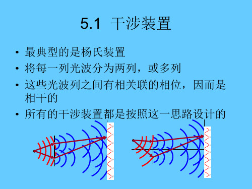
5.1 干涉装置
• 最典型的是杨氏装置 • 将每一列光波分为两列,或多列 • 这些光波列之间有相关联的相位,因而是
相干的 • 所有的干涉装置都是按照这一思路设计的
5.2 分波前的干涉装置
• 一.杨氏干涉 (双孔干涉或双缝干涉) • 每一孔或狭缝都是从光源发出的波场中的
一点,相当于将波前分割,然后相遇、交 叠,进行相干叠加。 • 称为分波前的干涉。 • 关键是设法获得两个或更多个相干的波列。
电信通讯英语精选 (2)

FM Facility Management 设备管理FM Fast Memory 快速存储器FM Fault Management 故障管理FM Feedback Mechanism 反馈机构FM File Management 文件管理FM fine magic 好戏法〖网语〗FM Flash Memory 瞬间存储器,快闪存储器,快擦型存储器(1980年日本东芝公司发明)FM Forms Management 窗体管理FM Frequency Meter 频率计FM Frequency Modulation 调频FM Function Manager 功能管理器fm Micronesia 密克罗尼西亚(域名).fm FileMaker Pro的电子表格文件格式〖后缀〗.fm1 Lotus 1-2-3 release 2.x的电子表格文件格式〖后缀〗.fm3 Harvard Graphics 3.0的设备驱动器文件格式〖后缀〗.fm3 Lotus 1-2-3 release 3.x的电子表格文件格式〖后缀〗FM / FDM Frequency Modulation / Frequency Division Multiplex 调频/ 频率分开多路复用FM / FDMA Frequency Modulation / Frequency Division Multiple Access 调频/ 频率分开多路访问FM / TDMA Frequency Modulation / Time Division Multiple Access 调频/ 时间分开多路访问FMA Failure Mode Analysis 故障模式分析.fmb WordPerfect for Win文件管理器按钮棒形图文件格式〖后缀〗FMC Fixed Message Cycle 固定讯号周期FMC Flexible Manufacture Cell 灵活制造单元FMC Force Majeure Clause 不可抗力条款FMC Full duplex Multiple line Control station 全双工多线路控制站FMCH FirMware CHannel 固件通道FMCW Frequency Modulated Carrier Wave 调频载波FMCW Frequency Modulated Continuous Wave 调频等幅波FMD Function Management Data 功能管理数据FMDEM Frequency Modulation DEModulator 频率调制解调器FMDM Frequency Modulation Deviation Meter 调频测偏计FME Frequency – Measuring Equipment 测频装置,频率计FMEA Fault Modes and Effect Analysis 故障模式与结果分析FMF File Microprogram Flags register 文件微程序标志(寄存器).fmf IBM LinkWay的字体图标文件格式〖后缀〗FMFB Frequency Modulation with Feed Back 反馈调频FMFF Frequency Modulation Feed Forward 调频前馈FMG Frequency Modulation Generator 频率调制发生器FMI Fast Multimedia Inc. 快速多媒体公司(美国,出品视频捕获卡)FMIC Frequency Monitoring and Interference Control 频率监听与干扰控制器FMID Function Modification IDentifier 功能修改标识符FMIS Finance Management Information System 金融管理信息系统.fmk Fortran PowerStation的文件编写格式〖后缀〗FML File Manipulation Language 文件操作语言FML Floating MuLtiply 浮点乘法FMLI Form and Menu Language Interpreter 表单菜单语言解释程序〖UNIX〗FMLP Fuzzy Multilayered Perception 模糊多层感知器FMM Flat Memory Model 平面内存模型FMM Modified Frequency Modulation 改进的频率调制.fmo dBase IV的编译文件格式〖后缀〗FMP Flow Management Protocol 流程管理协议FMPD Frequency – Modulation Predistortion 调频预失真FM-PM Frequency Modulation – Phase Modulation 调频-调相FMPP Flexible MultiPipeline Processor 多流水线软处理器FMR Facility Management Reporting 设施管理报告FMR Frequency Modulated Radar 调频雷达FMR Frequency Modulated Receiver 调频接收机FMS Facsimile Mail System 传真邮件系统FMS Fiber Management System 光纤管理系统FMS File Management System 文件管理系统FMS Financial Management System 财务管理系统FMS Flexible Manufacturing System 柔性制造系统FMS Fly Management System 飞行管理系统FMS FM Screening 散乱抖动〖打印机〗FMS Fortran Monitor System 公式翻译程序监视系统FMS Frequency Measuring Station 测频站FMS Frequency Modulation Synthesis 调频合成〖声卡〗.fmt FOXBASE的屏幕格式文件〖后缀〗.fmt Sprint的样式表文件格式〖后缀〗FMT Frequency Modulated Transmitter 调频发射机FMU File Memory Unit 文件存储单元FMV Full – Motion Video 全动视频,满帧速率电视FMV 富士通微机系列〖品牌〗FMVFT Frequency Modulated Voice Frequency Telegraph 调频音频电报FN Feedback Network 反馈网络FN Frame Number 帧编号FN Function Network 功能网络.fn3 Harvard Graphics 3.0的字体文件格式〖后缀〗FNA Free Network Address 网络空址FNA Fujitsu Network Architecture 富士通网络体系结构FNAE Free Network Address Element 网络空址要素FNB File Name Block 文件名称块FNB Flexible Network Bus 灵活性网络总线FNC Federal Networking Council 联邦网络化委员会(美国)FNI Firefly Networks Inc. “萤火虫”网络公司(美国,协作过滤技术的领导者,出品联机服务系统)FNP Front end Network Processor 前端网络处理器FNPA Foreign Numbering Plan Area 国外编号规划区FNR Fast Network Reconfiguration 快速网络重配置FNS Failure Notification Sheet 故障通知单FNS Federated Naming Service 联合命名服务FNS Feedback Node Set 反馈节点集FNS File Nesting Store 文件嵌套存储FNS Functional Nomenclature Signal 功能命名原则信号FNT FoNT 字体.fnt Bazier(贝氏)类型的字体文件格式〖后缀〗.fnx Exact的不活动字体文件格式〖后缀〗FO Fade Out 淡出,渐逝fo Faroe Island 法罗群岛(域名)FO Fiber Optic 光纤FO Frame Offset 帧偏移量.fo1 Borland Turbo C的字体文件格式〖后缀〗.fo2 Borland Turbo C的字体文件格式〖后缀〗FOA Fiber Optic Amplifier 光纤放大器FOAF Friend Of A Friend 朋友的朋友FOB Fiber Optics Bundle 光纤束FOBS Fiber Optic BoreScope 光纤管道镜FOC Fiber Optic Cable 光缆FOC Fiber Optic Communication 光纤通信FOC Fiber Optic Coupler 光纤耦合器FOCA Font Object Content Architecture 字体对象内容体系结构FOCC Forward Control Channel 前方控制通道FOCH FOrward CHannel 前方通道FOCIS Fiber Optics Communication and Information Society 光纤通信和信息协会FOCIS Financial On – line Customer Information System 金融联机用户信息系统FOCS Fiber Optic Communication System 光纤通讯系统focus 焦点网(首家由美国公司EnReach在中国投资经营的中文网站,1999,9)〖域名〗FOCUS Federation On Computing in the United State 美国计算联盟(国际信息处理联合会属下)FOCUS Fiber Optic Connection Universal System 光纤连接通用系统FOD Fax On Demand 传真求用系统FOD Formulas for Object Definition 对象定义公式FOD Function Operational Design 功能操作设计FODL Fiber Optic Delay Line 光纤延迟线FOG Fiber Optic Gyroscopes 光纤陀螺仪FOG Frequency Offset Generator 频率偏移发生器FOG-M Fiber Optic Guided Missile 光纤制导导弹FOG-V Fiber Optic Guided Vehicle 光纤制导运载工具FOI Fiber Optic Isolator 光纤隔离器FOIA Freedom Of Information Act 信息自由法案FOIL File – Oriented Interpretive Language 面向文件的解释语言,Foil 语言FOIRL Fiber Optic Inter Repeater Link 光纤的转发器间连接,中继器间的光纤链路FOIS Fiber Optic Interferometric Sensor 光纤干涉仪传感器FOL Fiber Optic Laser 光纤激光器.fol 1st Reader的保存信息文件夹格式〖后缀〗FOLAN Fiber Optic Local Area Network 光纤局域网FOM Fiber Optic Modem 光纤调制解调器FOMA Fiber Optic Medium Attachment 光纤媒体附加FOMDI Fiber Optic Medium Dependent Interface 光纤媒体从属接口FON Fiber Optic Net 光纤网.fon 字体文件格式〖后缀〗,电话簿文件格式〖后缀〗.fon Telix的拨号工商名录文件格式〖后缀〗.fon ProComm Plus的呼叫全程记录文件格式〖后缀〗FOOPS Functional Object – Oriented Programming System 面向功能对象的编程系统FOPEN File OPEN 文件打开FOPMA Fiber Optic Physical Medium Attachment 光纤物理媒体附加FOPT Fiber Optic Photo Transfer 光纤照片传送.for FORTRAN语言的源码文件格式〖后缀〗.for WindowBase的表单文件格式〖后缀〗FOREX FOReign EXchange 外汇FORM Fault Occurrence and Repair Models 故障发生和修理模型FORMAC Fiber Optic Ring Media Access Controller 光纤环媒体访问控制器FORMAL Formula manipulation Language 公式处理语言,Formal 语言format DOS外部命令:格式化软硬盘FORMAT FORtran Matrix Abstraction Technique Fortran语言矩阵提取技术FormatC “格式化C盘” :〖Word宏病毒〗FORMS Fiber Optic Reflect Memory System 光纤反射存储系统FORR Fiber Optic Ring Resonator 光纤环形共振器FORTRAN Formula Transformation 公式转换FORTRAN Formula Translation 公式翻译程序FORTRAN Formula Translator 公式翻译程序语言,Fortran 语言(微软于1977年开始发售)FOS File Organization System 文件组织系统FOS Follow – On Support 接续支持FOS FORTRAN Operating System FORTRAN操作系统FOS Function Operational Specification 功能操作说明FOSDIC Film Optical Scanning Device for Input to Computers 用于计算机输入的胶片光学扫描装置FOSI Formatting Output Specification Instance 格式化输出规格实例FOT Fiber Optics cathode ray Tube 光纤阴极射线管FOT Forward Transfer 向前传送FOT Frequency of Optimum Traffic 最佳通信量频率FOT Frequency of Optimum Transmission 最佳传输频率.fot True Type 的字库文件格式〖后缀〗FOTC Fiber Optic Trunk Cable 干线光缆,长途光缆FOTLAN Fiber Optic Tactical Local Area Network 光纤战术局域网FOTM Fiber Optic Test Method 光纤测试方法FOTN Fiber Optic Transmission Network 光纤传输网络FOTP Fiber Optic Test Procedure 光纤测试规程FOTS Fiber Optic Transmission System 光纤传输系统FOTSLH Fiber Optic Transmission System for Long Haul 远程光纤传输系统Founder 方正电脑,北大方正four 11 “411”:因特网的著名寻人网点,1998年并入雅虎〖域名〗Four Phase 四象限公司(美国,1969年推出第一个商用微处理器)FOV Field Of View 视图域.fox FOXBASE的伪编译程序文件〖后缀〗FOX Interactive 福克斯电影公司的多媒体部,专出影视剧软件(世界著名娱乐光盘制造商)FoxWeb “狐网”(数据程序交互使用工具)〖软件名〗FP Fabry – Pero Laser 法布里-泊罗激光器FP File Protect 文件保护FP Floating Point 浮点FP Function Processor 函数处理器FP Functional Programming 函数式编程语言.fp FoxPro的配置文件格式〖后缀〗FPA Failure Probability Analysis 故障概率分析FPA Fixed Point Arithmetic 定点算法FPA Flat Plane Antenna 平面天线FPA Floating-Point Accelerator 浮点加速器FPA Floating Point Arithmetic 浮点算法FPC File Parity Checks 文件奇偶校验FPC Fixed Point Calculation 定点计算FPC Fixed Program Computer 固定程序计算机FPC Forward Propagation Circuit 前推式传播线路FPC Full duplex Point to point Control station 全双工点到点控制站FPC Functional Processor Cluster 发挥作用的处理器簇.fpc FoxPro的目录文件格式〖后缀〗FPD Flat Panel Display 平面显示器FPD Full – Page Display 全页显示FPDS Federal Procurement Data System 联邦政府采购数据系统FPF Facility Parameter Field 设备参数域FPFU Fuji Photo Film USA Inc. 富士胶卷美国公司(出品数字相机)FPGA Field Programmable Gate Array 现场可编程门阵列FPIN Foreign Personal Identification Number 外来个人识别号码FPIS Forward Propagation by Ionospheric Scatter 电离层散射的向前传播FPL Floyd Evans Production Language 弗洛伊德·伊万斯的生成语言FPL Foxbord Programming Language Foxbord的程序设计语言FPL Frequency Phase Lock 频率锁相FPLA Field Programmable Logic Array 现场可编程逻辑阵列FPLMTS Future Public Land Mobile Telecommunication System 未来的公众陆地移动远程通信系统(第三代)FPLS Field – Programmable Logic Sequencer 域可编程逻辑音序器FPM Fast Packets Multiplexing 快速信息包多路传输FPM Fast Page Memory 高速页面存储器FPM Fast Page Mode 快页模式,快速页面模式〖奔腾主板〗FPM Fixed – Program Machine 固定程序计算机FPMA Fixed Preassigned Multiple Access 固定预分配多路存取FPML Financial Product Marker Language 金融产品标记语言FPM RAM Fast Page Mode RAM 快页模式随机存取存储器,快速页面模式随机访问存储器FPN Fixed – Pattern Noise 固定样式噪音FPN Fuzzy Petri Nets 模糊佩特里网FPNW File and Print Services For NetWare 用于“网器”的文件打印服务(微软的)FPO Federal Post Office 联邦邮局(德国)FPO For Position Only 只用于定位FPODA Fixed Priority Oriented Demand Assignment 面向固定优先权的请求分配〖多媒体〗FPOP Floating Point Operations Per Second 每秒浮点运算次数F-port Fiber Port 光纤端口FPP Fixed Path Protocol 固定路径协议FPP Floating Point Package 浮点软件包FPP Floating Point Process(or) 浮点处理(器)FPPA Fiber Patch Panel Assembly 光纤接插板装配FPR Fixed Point Representation 定点表示法FPR Fixed Program Receive 固定节目接受FPR Floating Point Register 浮点寄存器FPS Fast Packet Switching 通信包快速转接,快速数据分组交换FPS File / Print Server 文件/ 打印服务器FPS First Person Shooting Game 第一人称视角游戏〖游戏用语〗FPS Fixed Program Send 固定节目发送FPS Floating Point System, inc. 浮点系统公司(美国)FPS Focus Projection and Scanning (deflection system) 聚焦投影与扫描(偏转系统)FPS Fortran Processing System Fortram语言处理系统FPS Frames Per Second 每秒帧数.fpt FoxPro的备注字段文件格式〖后缀〗FPU Floating Point Unit 浮点单元〖处理器〗.fpw FloorPLAN plus for Windows的绘图文件格式〖后缀〗FQ Fair Queuing 公平排队FQ File Qualifier 文件限定词FQDN Fully Qualified Domain Name 正式域名,完全符合标准的域名FQL File Qualifier Length 文件限定词长度FQL Formal Query Language 正式查询语言FR Facility Request 设备请求FR Failure Rate 故障率FR Failure Record 故障记录FR Family of Requirement 必要条件系列FR Fault Recognition 故障识别FR Fault Report 故障报告FR Fault – Resilient 故障后可恢复原状的FR Fill Rate (像素)充填率〖显卡测试〗FR Forced Release 被迫发布FR Forms Registry 表单注册集FR Frame Relay 帧中继,帆分段传输,图文框接力传送(快速分组交换技术)fr France 法国(域名)FR Frequency Range 频率范围FR Frequency Relay 频率替续器FR Frequency Response 频率响应FR Full Rate 全速率FR Function Reference 函数指南FR Function Register 功能寄存器.fr3 dBase IV的重命名dBASE III+文件格式〖后缀〗FRA Failure Rate Average 平均故障率FRA Federal Radio Act 联邦无线电法案FRA File Relative Address 文件相对地址FRA Fixed Radio Access 固定无线接入FRAC Fixed Reservation Access Control 确定预约存取控制FRAC Fractionators Reflux Analog Computer 分馏回流模拟计算机FRAC Frame Relay Access Concentrator 帧中继接入集中器FRAD Frame Relay Access Device 帧中继访问设备,帧中继接入装置FRAD Frame Relay Assembler / Disassembler 帧中继汇编程序/ 反汇编程序FRAM Ferromagnetic RAM 铁磁随机存储器FRAM Functional Requirements Allocation Matrix 功能性需求分配矩阵FRAP Frame Relay Access Probe 帧中继接入探测器FRBS Federal Reserve Bank System 联邦储备银行系统(美国)FRBS Frame Relay Bearer Service 帧中继运载服务FRC Fault Reporting Center 故障报告中心FRC Federal Radio Commission 联邦无线电委员会(美国)FRC Final Routing Center 终极路由选择中心FRC Forward Read Continuous 连续向前读出FRC Functional Redundancy Checking 功能冗余检查FRCMS Frame Relay Congestion Management Scheme 帧中继拥塞管理方案FRD Failure Rate Data 故障率数据FRD Formulas for Relation Definition 关系定义公式FRD Functional Requirements Document 功能要求文件FRDS Failure Resistant Disk Systems 耐故障磁盘系统FRE Fast Routing Engine 快速路由选择引擎FRE Frame Relay Engine 帧中继引擎FRE Frame Relay Exchange 帧中继交换FRED Figure – Reader Electronic Device 图形阅读器电子器件FRED Figure Reading Electronic Device 电子读数器FREE First Ready First Execute 先就绪先执行Freeserve 免费服务公司(英国的网络公司)FREETECH 富基科技(台湾)FREQ-MULT FREQuency MULTiplier 频率倍增器,倍频器FRESA Frame Relay End – System Address 帧中继端系统地址FRESCAN FREquency SCANning 频率扫描FRESCANNAR FREquency SCANNing radAR 频率扫描雷达FRF Frame Relay Forum 帧中继论坛FRF Frame Repetition Frequency 帧重复频率.frf FontMonger的字体文件格式〖后缀〗FR-FR Frame Relay – to – Frame Relay 从帧中继到帧中继.frg dBase IV的未编译报告文件格式〖后缀〗FRI Finite Impulse Response 有限脉冲应答FRICC Federal Research Internet Coordinating Committee 联邦调研因特网协调委员会FRIF Frame Relay Information Field 帧中继信息域FRIL Fuzzy Relational Inference Language 模糊关系推论语言FRINGE File and Report INformation processing GEnerator 文件与报表信息处理生成器FRICC Federal Research Internet Coordinating Committee 联邦科研因特网协调委员会(美国)FRJ Facility ReJect 设备拒绝FRL Frame Representation Language 帧表示语言FRL Function Reference Listings 函数参照表FRM File Request Management 文件请求管理FRM Film Reading Machine 胶片阅读机FRM FRequency Meter 频率计.frm FOXBASE的报表文件格式〖后缀〗.frm dBase IV、Clipper 5和dBFast的报告文件格式〖后缀〗.frm 命令形式的文本文件格式〖后缀〗FRMR FRaMe Reject 帧拒绝.fro dBase IV的编译报告文件格式〖后缀〗FROM Fusible Read Only Memory 可熔断只读存储器.frp PerForm PRO Plus和FormFlow的表单文件格式〖后缀〗FRPI Flux Reversal Per Inch 磁通反转量/ 每英寸FRR Functional Recovery Routines 功能恢复例程FRS Fast Retrieval Storage 快速检索存储体FRS Forward Ready Signal 前方就绪信号FRS Frame Relay Services 帧中继业务FRS Frame Relay Switch 帧中继转换FRS Frame Relay Switcher 帧中继转换器FRS Fundamental Reference System 基本引用系统.frs WordPerfect的屏幕字体资源文件格式〖后缀〗FRSN Frame Relay Switch Node 帧中继转换节点FRT Failure Rate Test 故障率测试.frt FoxPro的报表文件格式〖后缀〗FRTF Fixed Radio Transmission Facility 固定式无线电播送设备FRU Field-Replaceable Unit 域可替换单元.frx FoxPro的报表文件格式〖后缀〗FS FacSimile 传真FS Factor of Safety 安全系数FS False Signal 错误信号FS Fast Select 快选Fs Femto second 飞秒,毫微微秒FS Field Separator 字段分隔符FS Field Strength 场强FS Figure Switch 数字开关FS File Separator 文件分隔符FS File Services 文件服务功能FS File Structure 文件结构FS Final Selector 最终选择器FS Finity State 有限态FS Fixed Station 固定台FS Fixed Subscriber 固定用户FS Floating Sign 浮点符号,浮标FS Follow Shot 随拍,移动拍摄FS Frame Scan 帧扫描FS Frame Status 帧状态FS Frame Store 帧存储FS Frame Switching 帧交换技术〖网络〗FS Frame Synchro 帧同步FS FreeSpace 《自由空间》〖游戏名〗FS Frequency Shift 频移FS Frequency Standard 频率标准FS Frequency Synthesizer 频率合成器FS Full Shot 全景镜头FS Full Status 完整状态FS Function Selection 功能选择FS Functional Symbol 功能符号FSA Frequency Stability Analyzer 频率稳定性分析仪FSAA Full Scene Anti – Aliasing 全景抗锯齿失真(加速芯片的功能)FSB File Cache Buffers 文件高速缓冲存储器缓冲区FSB Forward Space Block 正向间隔块FSB Front Side Bus 前端总线〖芯片组〗FSC Fault Simulation Comparator 故障模拟比较器FSC Fault Symptom Code 故障征兆代码FSC File Security Control 文件安全控制FSC Fixed Size Character 定长字符FSC Frequency Shift Converter 移频转换器FSC Fujitsu Software Corp. 富士通软件公司(日本,出品网络联组件)FSCB File System Control Block 文件系统控制块FSCS Frequency Shift Communication System 频移通信系统FSCS Fundamental Studies in Computer Science 计算机科学基础研究FSD Federal System Division (IBM) 联邦系统分部(属IBM公司)FSD Fixed Shroud Duplex 固定屏板双工操作FSD Full Scale Deflection 满度偏转,满刻度偏差FSDD Fibers with Slowly Decreasing Dispersion 缓降色散光纤FSDS Fairchild Software Development System 仙童软件开发系统FSDS File – System Descriptor Set 文件系统描述符集FSE Fractionally Spaced Equalizer 微弱间隔均衡器FSEC Federal Software Exchange Center 联邦软件交易中心(美国)FSF Fixed Sequence Format 固定顺序格式FSF Forward Space File 正向间隔文件FSF Free Software Foundation 自由软件基金会FSG Federated Systems Group 联合系统组FSI Fairchild Semiconductor Inc. “仙童”半导体公司(英特尔和AMD的前身)FSI Fault Symptom Index 故障征兆索引FSI Field – Sequential Illumination 场续照明〖投影仪〗FSI Fore Systems Inc. 前部设备系统公司(美国,出品网络适配器)FSI Frequency Subset Indicator 频率子集指示器FSI Funk Software Inc. “臭臭”软件公司(美国,出品网管工具)FSIOP File Server Input / Output Processor 文件服务器输入输出处理器FSIP Federal Security Infrastructure Program 联邦信息安全基础设施计划FSK Frequency – Shift Keying 频移键控FSKNRZ Frequency – Shift Keying, No Return to Zero 频移键控,不归零FSK TP Frequency – Shift Keying TelePrinter 频移键控电传打字机FSL Fast ethernet interSwitch Link 快速以太网互换开关链路FSL Finite State Language 有限状态语言FSL Font Selection Logic 字体选择逻辑FSL Formal Semantic Language 形式语义语言FSL Fujitsu System programming Language 富士通系统程序设计语言(为电子交换系统研制).fsl Paradox for Windows的表单文件格式〖后缀〗FSLT Fiber Optic Subscriber Line Terminal 光纤用户线路终端FSM Fast Screen Machine 快速筛选机FSM Field Strength Meter 场强计FSM Fine Striped Memory 细纹存储器,微带存储器FSM Finite State Machine 有限状态机FSM Folded Sideband Modulation 折叠边带调制FSM Forward Set – up Message 前方安装讯息FSM Frequency Shift Modulation 频移调制.fsm Farandoyle的音乐样本文件格式〖后缀〗FSN File Sequence Number 文件序号FSN Forward Sequence Number 正向序号FSN Frequency Subset Number 频率子集编号〖寻呼机〗FSN Full Services Network 全方位服务网络,综合信息网络〖因特网〗FSN Function Service Network 功能服务网络FSO Frequency Sweep Oscillator 扫频振荡器FSP File Services Processing 文件服务处理FSP File Service Protocol 文件服务协议FSP Fleet Scheduling Program 快速调度程序FSP Frequency Shift Pulse 频移脉冲FSP Full – Screen Processing 全屏处理FSP Functional, Security And Performance 功能安全和性能FSPG Fluorescent Security Photo Graphics 荧光防护照片制图FSR Feedback Shift Register 反馈移位寄存器FSR Forward Space Record 正向间隔记录FSR Frequency Shift Receiver 移频接收机FSS First Floor Software 基础软件FSS Fixed Satellite Services 固定卫星业务FSS Fixed Signal Services 固定信号服务FSS Flying Spot Scanner 飞点扫描仪FSS Fragment Free Switching 不分段切换FSS Frames Services 帧服务FSS Full – Screen Scaling 全屏幕缩放FST Facilities Solution Team 设备疑难解答组FST Field STart 字段开始FST File Status Table 文件状态表FST Frequency Shift Transmission 移频传输FST Full STore 存满,存储器满.fst dBFast的可链接程序文件格式〖后缀〗FSTC Finance Service Technology Committee 金融服务技术委员会FSTS Functional Standard Test Specification 功能标准测试规范FSU Facsimile Switching Unit 传真转接器FSU Final Signal Unit 最终信号单元FSVFT Frequency Shift V oice Frequency Telegraph 移频音频电报FSW Frame synchronization Word 帧同步字.fsx Lotus 1-2-3的数据文件格式〖后缀〗FT Fault Tolerance 容错FT Foreign Transaction 外来事务处理FT Fourier Transform 傅里叶变换FT Fractional T1 部分T1线路(提供T1线路部分带宽的数字电话服务)〖视频会议〗FT Frame Transfer 帧传送FT Frederick Terman 弗雷德里克·特曼(硅谷之父)FT Functional Test 功能测试FTA Fast Turn Around 快速周转FTA Fault Tree Analysis 故障树状分析FTA Floptical Technology Association 软盘技术协会FTAM File Telecommunication Access Method 文件远程通信访问方法FTAM File Transfer Access and management 文件传送存取与管理〖国际标准〗FTAM File Transfer And Access Method 文件传送和存取法〖国际标准〗FTAMS File Transfer Access and management Services 文件传送存取和管理服务FTBF Frequency Tuned Bandpass Filter 频率调谐带通滤波器FTC Fast Time Constant 快速时间常数(电路)FTC Fast Time Control 快速时间控制FTC Fault – Tolerant Computer 容错计算机FTC Fault Tolerant Computer 容错计算机FTC Frequency Time Control 频率时间控制FTC Frontier Technologies Corp. 边疆技术公司(美国,出品网络群件)FTC Fuji Telecasting Company Ltd. 富士电视广播公司(日本)FTC The Federal Trade Committee 联邦贸易委员会(美国)FTDS Failure Tolerant Disk Systems 容错磁盘系统FTE Frequency Translation Equipment 频率转换设备FTE Functional Test Equipment 功能测试设备FTF Fast Transversal Filter 快速横向滤波器FTG FighT Game 格斗游戏FTG File Tag Gate register 文件标记门(寄存器)FTI File Tag In register 文件输入标志(寄存器)FTI Fixed Time Interval 固定时间间隔FTL Fast Transient Loader 快速瞬态装入程序FTL Fiber in The Loop 循环光纤FTLAN Fault Tolerant Local Area Network 容错局域网FTM Fiber Termination Module 光纤端接组件FTM File Transfer Manager 文件传送管理器FTM File Transfer Mode 文件传送模式FTM Frequency Time Modulation 频率时间调制.ftm Micrografx的字体文件格式〖后缀〗FTMC Frequency and Time Measurement Counter 频率时间测量计数器FTO File Tag Out register 文件输出标志寄存器FTOP Frequency TOP 最高频率FTP Field Test Procedures 域测试规程FTP (The basic Internet File Transfer Protocol) 因特网基本文件传送协议(网络主机间传送文件的服务协议),档案传送通讯协定(台湾用语)〖因特网〗FTP Foil Twisted – Pair 箔双绞线.ftp FTP Software PC/TCP的配置文件格式〖后缀〗FTPD File Transfer Protocol Daemon 文件传送协议驻留程序〖因特网〗FTPI Flux Transitions Per Inch 磁通转变次数/ 每英寸FTPSVR File Transfer Protocol for Server 服务器文件传送协议FTR Fast Token Ring 快速令牌环FTR File Transfer Requests 文件传送请求FTR Filestore Transfer Routine 文件存储传送例程FTR Full Text Retrieval 全文检索FTR Functional Test Report 功能测试报告FTR Functional Test Request 功能测试请求FTS Fast Track Selector 快速磁道选择器FTS Federal Telecommunication System 联邦远程通信系统(美国)FTS Field Test Support 域测试支持FTS Forward – Transfer Signal 向前传送的信号FTS Frame Transfer System 帧传送系统FTS Free Time System 自由时间系统FTS FutureTech System Inc. 未来技术系统公司(美国,出品笔记本电脑)FTSC Federal Telecommunications Standards Committee 联邦远程通信标准委员会(美国)FTSP Federal Telecommunications Standards Program 联邦远程通信标准计划FTTB Fiber To The Building 光纤到建筑物FTTC Fiber To The Curb 光纤到路边FTTC Fiber To The Customer 光纤到用户FTTH Fiber To The Home 光纤到家FTTO Fiber To The Office 光纤到办公室FTTS Fiber To The Subscriber 光纤到用户FU Fetch Unit 引入单元FU Field Unit 字段单元,信息组单元FU Flight Unlimited 《无限飞行》〖游戏名〗FU Follow – Up 随动FU Functional Unit 功能部件FUA Follow – Up Amplifier 随动放大器FUA frequently used acronyms 常用缩略语〖网语〗Fujitsu 富士通株士会社〖厂标〗FUM Full User Move 用户整体迁移FUN Frye Utilities for Networks 弗赖伊网络实用工具〖软件名〗FUN FUNction 功能,函数,操作FUNI Frame User – to – Network Interface 帧用户到网络接口FUNI Frame – Based User – to Network Interface 基于帧的用户到网络接口FUR Fast Update Request 快速更新请求FV Formula Visualizer 公式可视表述器FV Future Vision 美国“前景”公司(世界著名娱乐光盘制造商)FVC Forward Voice Channel 前推式语音通道FVC Frequency to V oltage Converter 频率-电压转换器FW Fast Write 快写技术〖显卡〗FW Fire Wire “火线”,即IEEE1394(高速外部总线标准)FW FirmWare 固件FW First Word 首字FW Forward Wave 前向波FW Frame Window 框架窗口〖编程〗FW Full Wave 全波.fw FrameWork的数据库文件格式〖后缀〗.fw2 Framework II的数据库文件格式〖后缀〗.fw3 Framework III的数据库文件格式〖后缀〗FWA File Working Area 文件工作区FWA First Word Address 首字地址FWA Fixed Wireless Access 固定无线访问FWA Forward Wave Amplifier 前向波放大器FWA Full – Wave Amplifier 全波放大器FWAC Four Wire Automatic Converter 四线自动转换器FWBA Full – Wave Balanced Amplifier 全波平衡放大器FWCFA Forward Wave Cross Field Amplifier 前向波交叉场放大器FWD Free World Dialup 全球免费拨通,全球免费呼叫FWH Fire Ware Hub 火器集线器〖主板〗FWH Firm Ware Hub 固件集线器,固件中心〖芯片组〗FWHM Full Width at Half Maximum 一半最大值的充足带宽FWIW for what its worth 为其所值〖网语〗FWL Fixed Word Length 固定字长FWM Four – Wave Mixing 四波混合FWR Full – Wave Rectifier 全波整流器FWSE Frequency – Weighted Squared Error 频率加权平方误差FWT Fast Walsh Transform 快速沃尔什变换FWT Fast Wavelet Transform algorithm 快速子波变换算法FWTS Federal Wireless Telecommunications Services 联邦无线远程通信业务.fx FastLynx的在线线导文件格式〖后缀〗FXBIN decimal to FIXed BINary translation 十进制到固定二进制转换FXC Foreign eXchange Circuit 外来交换机线路,国际交换电路.fxd FAXit的电话号码簿文件格式〖后缀〗FXO Foreign eXchange Office 国际交换局.fxp FoxPro的编译文件格式〖后缀〗FXS Foreign eXchange Service 国际交换业务,外汇兑换业务.fxs WinFax的传真传送图形文件格式〖后缀〗FXT Fixed Time Call 定时呼叫FYA for your amusement 供您消遣〖网语〗FYI for your information 仅供参考〖网语〗FYI 福杨主板〖代号〗。
干涉星敏感器测角精度影响因素的研究

文章编号 2097-1842(2023)06-1433-09干涉星敏感器测角精度影响因素的研究阮宇翔1,2,董 磊1 *(1. 中国科学院 长春光学精密机械与物理研究所, 吉林 长春 130033;2. 中国科学院大学, 北京 100049)摘要:为了提高传统星敏感器的姿态测量精度,可将干涉测角技术与传统星敏感器相结合,即在传统星敏感器质心定位技术的基础上,利用星像点的光强信息进一步进行细分,从而突破了质心定位的精度限制,形成具有大视场高精度的干涉星敏感器。
本文对制约干涉星敏感器测角精度的因素进行深入研究,重点研究干涉条纹的分割误差对测角精度的影响机理。
通过研究分析,得出以下结论:光锲阵列不等分误差不是影响干涉星敏感器测角精度的主要因素;莫尔条纹周期与光楔阵列整体通光尺寸不匹配误差小于1%时,可保证单因素测角误差小于0.01";对于莫尔条纹取向与光楔阵列排布方向不正交误差,条纹旋转角度应当小于0.1°,可保证单因素测角误差小于0.01"。
所以,应在实际加工与装调过程中抑制上述两个主要误差,从而使干涉星敏感器的实际测角精度接近高精度理论值。
关 键 词:干涉星敏感器;干涉测角技术;干涉条纹;相位估计;测角精度中图分类号:O439 文献标志码:A doi :10.37188/CO.2022-0232Influencing factors of angle measurement accuracy ofan interferometer star trackerRUAN Yu-xiang 1,2,DONG Lei 1 *(1. Changchun Institute of Optics , Fine Mechanics and Physics , Chinese Academy of Sciences ,Changchun 130033, China ;2. University of Chinese Academy of Sciences , Beijing 100049, China )* Corresponding author ,E-mail : nodepression@Abstract : In order to improve the traditional attitude measurement accuracy of star sensors, interference angle measuring technology can be combined with a traditional star sensor. Based on the centroid position-ing technology of traditional star sensors, the light intensity information of star image points is subdivided to break through the accuracy limitation of centroid positioning and obtain a highly precise interferometric star sensor with a large field of view. In this paper, the factors that restrict the angle measurement accuracy of in-terferometer sensors are deeply studied with particular interest given to the influence of interference fringe segmentation error on angle measurement accuracy. Through research and analysis, we conclude that the asymmetry error is not the main factor affecting the angle measurement accuracy of interferometric sensors.收稿日期:2022-11-14;修订日期:2022-12-12基金项目:国家自然科学基金(No. 11703024)Supported by National Natural Science Foundation of China (No. 11703024)第 16 卷 第 6 期中国光学(中英文)Vol. 16 No. 62023年11月Chinese OpticsNov. 2023When the mismatch error between the Moire fringe period and the overall optical dimension of the optical wedge array is less than 1%, the single-factor angle measurement error is less than 0.01". For non-orthogonal error between Moire fringe orientation and an optical wedge’s array arrangement direction, the accuracy er-ror of single-factor angle measurement is sure to be less than 0.01" when the fringe rotation angle is less than 0.1°. Therefore, the above two main errors should be suppressed in the production and assembly so that the measurement accuracy of the interferometer sensor is closer to the high-precision theoretical value.Key words: interferometer star tracker;interferometric angle measuring technique;interference fringe;phase estimation;angle measuring accuracy1 引 言星敏感器是一种高精度的姿态敏感测量仪器,在航天器姿态控制系统中起着重要作用,并且在导弹制导系统、激光指向传感器系统和深空激光通信系统等方面也得到了广泛的应用[1-4]。
干涉型光纤传感器偏振衰落动态补偿技术

图 2:混合效率变化图 Fig 2: Mixing efficiency variation graph
零差解调技术较好地消除相位衰落的基础上,利用旋转的半波片可以动态补偿由环境变化引 起的偏振衰落。通过计算模拟证明了理论分析的正确性。该方案具有结构简单,成本低廉的 特点。
二 结构与分析
如图 1 所示,低频振荡的PZT1 用来模拟待测信号,高频振荡的PZT2 结合相位生成载波 零差解调电路用来补偿相位衰落[3]。本装置创新地在参考臂上加入了可旋转控制的半波片, 把干涉信号通过驱动电路反馈给步进电机以控制半波片的旋转,从而达到动态补偿偏振衰落 的目的,以下对其进行理论分析。
干涉型光纤传感器偏振衰落动态补偿技术
吴许强 俞本立 孟军 穆姝慧 孙维亚
安徽大学物理系 230039 摘要:由单模光纤制作的光纤传感器常会因外部环境扰动而引起相位衰落和偏振衰落。目前 相位补偿技术已经比较成熟,而偏振衰落已成为阻碍其实用化的重要因素。本文在相位补偿 的基础上提出了一种动态补偿偏振衰落的方法并对其进行了理论分析。本技术的关键是在干 涉仪的参考臂中引入一个可以旋转控制的半波片。把干涉信号的幅值变化通过驱动电路反馈 给步进电机,步进电机旋转该半波片以调整干涉信号的幅值。据此可实现偏振衰落的动态补 偿,可使偏振衰落造成的信号幅度波动不大于 3dB。 关键词:光纤干涉仪 动态补偿 偏振衰落 半波片
Dynamic Compensation Technique for Polarization Fading in
光电英语词汇(I2)
光电英语词汇(I2)光电英语词汇(I2)光电英语词汇(I2)integrating capaciotor 积分电官integrating circuit 积分电路integrating detector 积分探测器integrating exposure meter 积分曝光计integrating filter 积分滤波器integrating motor 积分电动机integrating photmeter 积分光度计integrating photometer 积分光度计integrating sphere 积分球integrating spheres 积分球integration circuit 积分电路integration constant 积分常数integration filter 积分滤波器integrator (1)积分器(2)积累器intelligence (1)智能(2)情报,信息intenisty of spectral line 谱线强度intense colour 强色intense laser radiation 强激光辐射intense light pulse 强光脉冲intense light source 强光源intense tunable ir source 强可调红外源intensification 增强,强光intensified vidicon 增强视像摄影管intensifier 增强器intensifying foil 箔制增光屏intensity 强度intensity control 强度控制intensity convolution integral 强度卷积积分intensity diffration pattern 强度衍射图样intensity distriubtion 强度分布intensity fluctuation 强度起伏intensity impulse response 强度脉冲响应intensity interferometer 光强干涉仪intensity level 强度级intensity modulation 强度调制intensity of color 色强度intensity of ilumination 照明强度,照度intensity of pressure 压强intensity scale esneitometer 光强感光度计intensity spectrum 强度谱intensity transfer function 强度传递函数intensive reflector 强光反射镜inter-frame redundancy 帧间多余信息inter-image effect 像界效应inter-relation 相互关系interactive 交互作用的interacvity (1)内共振腔,内腔(2)腔内interatomic collisions 原子间碰撞interaxial angle 轴间角interaxial mode beat frequency 轴间模拍频interband transition 带间跃迁intercalibration 相互校准intercept ground-based optical recorder 监听地面光记录仪interchangable lens 可换镜头interchangeability 交换性,互换性interchangeable lens 可互换透镜interchangeable mirror 可换反射镜interconersion 相互转化intercorrelation 相互关intercoupling 寄生耦合intercrystalline 晶粒间的intercrystalline barrier 晶间势垒interdiffusion 相互扩散interelectrode 极间的interelectrode capacitance 极际电容interelectronic 电子间的interface (1)界面(2)相互关系interface energy 分界面能interface scattering 界面散射interfacial angle 晶面角interfacial film 界面膜interference (1)千涉(2)干扰interference absorber 干涉吸收体interference color 干涉色interference colors 干扰色interference condition 干涉条件interference contrast 干涉对比interference contrast microscopy 干涉对比显微术interference drag 干涉曳力,干涉阻力interference figure 干涉图形interference filter 干涉滤光器interference filters 干涉滤光镜interference fit 干涉配合interference fringe 干涉条纹interference function 干涉函数interference grating 干涉光栅interference inverter 干涉反演器interference microscope 干涉显微镜interference microscopy 干涉显微术interference modulation 千涉调制interference of equal inclination 等倾干涉interference of equal thickness 等厚干涉interference of light 光的干涉interference of overlapping of orders 叠级干涉interference order 千涉级interference path difference 干程程差interference pattern 干涉图形interference reflector 干涉反射镜interference ring 干涉环,干涉圈interference spectrometer 干涉光谱计interference spectroscope 干涉分光镜interference spectroscopy 干涉分光光谱学interference spectrum 干涉光谱interference surface micrscope 表面干涉显微镜interference tube 干涉管interference wave 干涉波interference-free (1)无干涉的(2)无干扰的interferences/differential interference contrast microscopes 干涉显微镜,微分干涉对interferend refractometer 干涉折射计interfermetric micrscopy 干涉测量显微术interfermetric radiometer 干涉辐射计interferogram 干涉图interferogram technique 干涉图技术interferography 干涉像术interferometer 干涉仪interferometer modes 干涉仪类型interferometer optics 干涉仪光学interferometer spectroadimeter 干涉分光辐射计interferometric calorimetry 干涉测热术interferometric filter 干涉滤光片interferometric null method 干涉测量零点法interferometry 干涉量度学interferoscope 干涉镜interfringe 条纹间的intergalactic space 星系际空间intergating gyroscope 积分回旋器,积分陀螺interior focusing 内调焦interior screw 内螺旋interior sub-multiple angles 内等分角interiror focusing telescope 内调焦望远镜interlaced scanning 隔行扫描interlayer 界层,隔层interlayer effect 界层效层interleave scanning 隔行扫描interlock (1)联锁,闭锁(2)连接interlocking device 联锁装置intermediary image 中间像intermediate axle 中间轴intermediate fequency 中频intermediate frequency (if)中频intermediate frequency transformer 中频变压器intermediate gear 中速齿轮,二档齿轮intermediate herschek effect 中度赫谢效应intermediate image 中间成像intermediate infrared region 中红外区intermediate level 中间能级intermediate wae 中波intermediate-index layer 中间折射率层intermeshed scannning 隔行扫描intermetallic compound semiconductor 金属间化合物半导体intermittency effect 断续效应intermittent camer 断续式摄影机intermittent exposure 断续曝光intermittent illumination 断续照明intermittent noise 断续噪声intermittent sprocket 断续链轮intermode beats 模间拍intermode spacing frequecny 模间间隔频率intermodulation 互调intermodulation distortion 互调变失真,模间失真intermodulation effect 互调制效应intermodulation interference 互调干扰internal 内部的internal absorptance 内吸收比internal absorption factor 内吸收因数internal adjustment scope 内调式瞄准镜internal calibration 内校准internal caliper gage 内径卡规internal conical refraction 内锥形折射internal conversion 内转换internal defocusing 内散焦internal dial gage 内径千分表internal diamteter 内径internal exposure (1)内曝光(2)内照射internal field 内场internal focusing 内调焦internal focusing telescope 内调焦望远镜internal gating 内选通,内开关作用internal gauge 内径规internal measuring instrument 内径测量仪器internal photoeffect 内部效应internal photoelectric effect 内部光电效应internal photolectric effect 内光电效应internal quanntum efficiency 内量子效率internal reflection 内反射internal reflective cavity 内反射腔internal reflector 内反射镜internal scanned laser 内扫描激光器internal self-defocusing 内自散焦internal self-focusing 内自聚焦internal standard 内标准internal standard line 内标准线internal stress 内胁强,内应力internal surface 内表面internal transmittance 内透射比internal-standard line 内标线internally loss modulated laser 内损耗调制激光器internally modulated gas laser 内调制气体激光器internally phase modulated laser 内相位调制激光器internation standard 国际标准international bureau of weights and measures 国际计量局international coulomb 国际库仑international organization for standardization (iso)国际标准化组织international organization of legal metrology 国际法制计量组织international prototype 国际原型international standard atmosphere 国际标准大气压international standardization association (i.s.a)国际标准化协会international system of units (si system)国际单位制international telecommunication satellite consortium (intelsat)国际通信卫星组织internnational candle 国际烛光interocular distance 瞳孔间距离interocular kistance 眼珠间距interorder distance 干涉带间距interphako interference microscopy 显微剪切干涉术interphase transformer 相间变压器interplanar distance 晶面间距interplanetary 行星际的interplanetary communication 行星际通interplanetary navigtion 行星际导航interplanetary space 太空interplanetrary flight 行星际航行interplay 相互作用interpolating coding area 插值编码区域interpolation 插值法,插值,内插法interpolation error 插值误仪interpolation formula 插值公式interpolation function 插值函数interpole 间极interpretation (1)解释,翻译(2)译码interpreter 直译程式,转译程式interpreter code 伪码interpretoscope 判读机interpupillary adjustment 光瞳间距调节interpupillary distance 瞳间距离interpupillary distance (ipd)光瞳间距调节interpupillometer 光瞳间距仪interrupt 中断,岔断interrupt flip-flop 中断触发器interrupted wae 间歇波interrupter (1)断续器(2)斩波器interrupter disk 斩光盘interruption (1)中断(2)阻挡interscan 中间扫描intersecting axle 交叉轴intersecting line 交叉线intersection (1)交叉(2)交叉intersection point 交点interspace (1)间隙(2)星际interstage 级际的,级间的interstellar absorption lines 星际吸收线interstellar gas 星际气体interstellar line 星际谱线interstellar spectrum 星际谱interstellar vehicle 星际飞船interstital site 填隙座interstitial fibre 隙间光纤intersymobl interference 码间干扰intersystem crossing tansition 系际交叉跃迁interval (1)间隔(2)区间intervalometer 曝光控制器intesifying cscreen 增光屏intraacvity loss modulation 腔内损失制intraband photoconductivity 带内光电导性intrabeam viewing 光束内视intracavity acoustic modulation 腔内声调制intracavity diffraction grating 腔内衍射光栅intracavity electroptic modulator 内腔式电光调解制器intracavity gas laser 内腔式气体激光器intracavity laser modulation 腔内激光调制intracavity prism 内腔式棱镜intracity dye-laser 内腔式染料激光器intracvavity resonantor 内腔式共振器intracvity image converter 内腔式变像管intralens reflection 透镜内反射intramodal distortion 模内畸变intramode 模内intraocular 眼内的intraocular fluid 眼内充填用液体intraocular gas 眼内充填用气体intraocular lens 人工水晶体intraocular lens guide 人工水晶体导引器intraocular pressure measuring device 眼内压测试装置intraretional 视网膜内的intravity phase modulation 腔内相调制intrinsic 本徵的,固有的,内禀的intrinsic brighness 固有亮度intrinsic carrier 本徵载流子intrinsic crystal 本徵晶体intrinsic defect 内在缺陕intrinsic detector 本微探测器intrinsic error 固有误差intrinsic flux density 本质通量密度intrinsic germanjum photodiode 本徵锗光电二极管intrinsic impedance 固有阻抗intrinsic linewidth 本徵线宽intrinsic loss 本徵损失intrinsic photoconductior 本徵光电导体intrinsic photoconductivity 内禀光电导性intrinsic photoemission 内禀光电发射intrinsic scattering 本徵散射intrinsic semiconductor 本徵半导体intrinsic transistor 本征晶体管introscope 内窥镜,内视镜intrusion detector 插入式探测器invar 殷钢invar tape 殷钢带invariance (1)不变性(2)不变式invariance of liner systemm 线性系统不变性invariant 不变量invariant scalar 不变标量inverse 倒逆,反向,倒置inverse bremsstrahlung 逆轫致辐射inverse compton effect 倒康普顿效应inverse correlation 逆相关inverse feedback 贫反馈inverse fllter 逆滤波器inverse fourier transform 傅里叶逆变换inverse matrix 逆矩阵inverse peak voltage 逆向峰值电压inverse piezoelectric effect 光电逆效应inverse problem 可逆问题,倒问题inverse proportion 反比例inverse raman effect 倒喇曼效应inverse raman scattering 反转喇曼散射inverse ratio 反比inverse relaxation 反弛豫inverse square law 平方反比率inverse stark effect 倒斯塔克效应inverse transform 逆变换inverse trigonometrical function 反三角函数inverse voltage 反转电压inverse zeeman effect 侧塞曼效应inverse-frequency spectrum 反转频谱inversion level 反转能级inversion mechanism 反转机制inversion prism 倒像棱镜inversion pump rate 反转抽运速率inversion symmetry (1)反向对称(2)镜面对称invert unit 倒相器inverted image 倒像棱镜inverted lamb dip 倒兰姆凹陷inverted microscope 倒显微镜inverted population density 反转粒子数密度inverted spectral term 倒光谱项inverted t-slot 倒丁字槽inverted telectphoto objective 倒远摄物镜inverted telphoto lens 倒远距照相镜inverter (1)变换器(2)倒相器(3)转换开关invertibility 可逆性invertible matrix 可泄矩阵inverting eyepiece 倒像目镜inverting parametric device 倒反参变装置inverting prism 倒像棱镜inverting range finder 倒像测距仪invesrsion spectrum 反转谱invisible chromatogram 不可见色谱图invisible light filter 不可见光滤波器invisible light filters 不可见的光滤器invisible line (1)隐线,虚线(2)不可见谱线invisible radiation 不可见辐射invisible ray 不可见射线invisible spectrum 不可见辐射谱involute 渐开线,渐伸线involute curfe 渐开线齿轮involute gear 渐开线齿条involute rack 渐开线齿条involute tester 渐开线检查仪involute worm 渐开线蜗杆involution (1)乘方(2)对立inwall 内壁inward curving field 向内弯曲场iodide 碘化物iodine (i)碘iodine cycle 碘循环iodine laser 碘激光器iodine photodissociation laser 碘光解激光器iodine stabilized laser 碘稳频激光器iodine tungste filament lamp 碘钨灯ion 离子ion activity electrode 离子活性电极ion avalanche 离子雪崩ion beam 离子束ion bombardment 离子虫击ion chamber 离子室ion choncentration 离子浓度ion contamination 离子污染ion emission 离子发射ion exchange 离子交换ion exchange chromatorgraphy 离子交换色谱法ion exchange resion 离子交换脂ion exchange technique 离子交换技术ion focujsing 离子聚焦ion gas laser 离子气体激光器ion grid theory 离子栅极说ion image 离子像ion implantation 离子注入ion implantation equipment 离子植入机ion laser 离子激光器ion microprobe mass spectrometer 离子探针质谱仪ion microscope 离子显微镜ion mobility 离子迁移率ion pair 离子对ion polishing 离子抛光ion tarnsition 离子跃迁ion-acoustic fluctuation 离子声起伏ion-acoustic turblence 离子声湍流ion-diple bond 离子偶极键ion-exchange electrolyte cell 离子交换电解电池ion-heated cathode 离子加热阴极ionic birefringence 离子双折射ionic bonding force 离子链合力ionic crystal 离子晶体ionic focusing 离子聚焦ionic link 离子键ionic polarizaton 离子极化ionium (io)锾ionization 电离,离子化ionization chamber 电离室,游离室ionization energy 电离能ionization gauge 电离规ionization potential 电离电位ionization spectrometer 游离分光计ionization time 电离时间ionization vacuum gauge 游离真空计ionization voltage 电离电压ionized acceptor 离子化受主ionized argon laser 氩离子激光器ionized gas 电离气体,离子化气体ionized laser plasma 电离激光等离子体ionized layer 电离层ionized stratum 电离层ionizing radiation 致电离辐射ionogam 电离圆ionography 离子摄影ionosphere 电离层ionospheric storm 电离层风暴ionospheric wave 电离层波iontegration (1)积分法(2)集成iosotope mixture 同位素混合物ir airglow 红外大气光辉光ir camouflage-dectection camera 假目标红外探测相机ir detector 红外探测器ir diode laser 红外二极管激光器ir filter 红外滤光片ir fringe computer 红外条纹计算机ir guided warhead 红外制导弹头ir horizon sensor 红外地平传感器ir imaging senor 红外热像仪ir laser tracker ranger 红外激跟踪测距仪ir modulated ellipsometry 红外调制椭圆测量术ir optical component 红外光学部件ir phosphor 红外磷光体ir picture 红外图像ir recording equipment 红外记录仪ir response 红外响应ir scanning camera 红外扫描照相机ir seeker 红外寻的器,红外搜索器ir senor 红外传感器ir window 红外窗ir-aimed lidar 红外瞄准激光雷达ir-radiometer 红外辐射计ir-transmission glass 透红外玻璃iraser (1)红外激射(2)红外激射器irdome 红外整流罩iridescence 虹彩iridescent color 彩虹色iridium (ir)铱irirs change mechmaism 可变光阑变化机制iris (1)虹膜(2)可变光阑iris aperture 可变光阑孔径iris blade 可变光阑片iris diaphragm 可变光阑iris diaphrams (stops),apertures 虹膜光阑,孔径iris mount 可变光阑套iris photometer 可变光阑光度计iris ring 可变光阑环iron (fe)铁iron arc 铁电弧iron oxidfe 氧化铁iron sulfide film 硫化铁膜irradiance 辐照度irradiant (1)光照的(2)光亮的irradiated gas 受辐照气体irradiated surface 受辐照表面irradiation (1)发光(2)辐照(3)光渗irradiation bomb 照明弹irradiator 辐照器irradome 红外整流罩irrationa dispesion 无理色散,不规则色散irrational (1)无理数(2)无理的irreducible matricx 不可约阵irreflexive 漫反射的irregar array irrelevant image 不相关像irreqularity 不规则性irreueible componet 不可射成分irreversibility 不可逆性irreversible circulation 不可逆循环irreversible laser damage 不可逆激光损伤irreversible reaction 不可逆反应irrgular movement 不规则运动irrgular reflection 不规则反射irrgular refraction 不规院折射irrgular spiking 不规则尖峰irrgularity of inter-ference fringe 干涉条纹不规则性irrotational (1)无旋的,非旋转的(2)非旋光的irrotational vector 无旋矢量irtran-i 艾尔特兰-i irtran-ii 艾尔特兰-ii irtron 红外光雷管ischromtic stimuli 等色剌激iscolinic 等倾线isentropic (1)等熵线(2)等熵的isis wave-beam device 可变光阑波束装置islometer (1)同分异构体(2)同质累能素iso code 国际标准码iso speed standard 国际感光度标准isobar (1)等压线(2)同量异位素isobric line 等压线isocandela diagram 等烛光图isocandla diagram 等烛光图isochromatic 等色的isochromatic (orthochromatic)等色的isochromatic line 等色线isochromatic lines 等色线isochromatics 等色性isochromatics-isopachices patern 等色-等厚线图样isochronis, 等时性isochronous scanning 同步扫描isocmetric projection 等角投影isodiffusion surface 等漫射面isodivs 等布图isoelastic 等弹性的isoelcectronic transition 等电子跃迁isoelectronic sequence 等电子数序isogonic mapping 等角测绘isogonic tranformation 等角变换isogyre 同消色线isohedral 等面的isolation (1)绝绿(2)隔离isolation mounting 隔离装置isolator (1)绝缘体(2)隔离器isoline 等值器isomeride 同分异构体isomerism 同质异能性isometric (1)等轴的,立方的(2)等量的isometric system 立方晶系isometrics 等体积线,等容线isometropia 同等视觉isomrorphis 同晶性,同构性isomrphic substance 同晶型物质isopach 等厚线isopache measurment 等厚测量isopanchromatic film 等全色胶片isophase 等相线isophlanatic image formation 等晕成像isophote 等照度线isophotometer 等光度计isoplanatic 等平面的isoplanatic condition 等晕条件isoplanatic patch 等晕面元isoplanatic region 等晕区isoplanatism 等晕现象isopreference curves 等如曲线isorotation 等旋光度isorphous crystal 同形晶体isospace 同空间isosrbs 等吸收isostaic ajdusment 均衡调整isotemperature line 等温线isotherm 等温线isothermal solid region 等温固态区isotojpic abundance 同位素丰度isotope 同位素isotope enrichment 同位素浓缩isotope excitation 同位素激发isotope lamp 同位素灯isotope separation 同位素分离isotope shift 同位素移动isotrocpic material 各向同性材料isotropic 各自同性的isotropic crystal 各向同性晶体isotropic material 各向同性材料isotropic medium 各向同性媒质isotropic radiator 各自同性辐射体isotropic resolution 各向同性分解isotropic scatterning 各向同性散射isotropism 各向同性现像isotropy 各向同性itensified image 增强像iteration correction 迭代校正iterative method 迭代法itercnnection 互连iterfermetry 干涉量度学itermolecvular 分子间的itersatllite communication 卫星间通信itnersection height 交点高度ito glass substrate 导电膜玻璃基板itracavity modulation 腔内调制itv 工业电视iversion density 反转密度ivory 象牙色光电英语词汇(I2) 相关内容:。
稳定的高功率激光系统在高级引力波探测器中的应用

Stabilized high-power laser system forthe gravitational wave detector advancedLIGOP.Kwee,1,∗C.Bogan,2K.Danzmann,1,2M.Frede,4H.Kim,1P.King,5J.P¨o ld,1O.Puncken,3R.L.Savage,5F.Seifert,5P.Wessels,3L.Winkelmann,3and B.Willke21Max-Planck-Institut f¨u r Gravitationsphysik(Albert-Einstein-Institut),Hannover,Germany2Leibniz Universit¨a t Hannover,Hannover,Germany3Laser Zentrum Hannover e.V.,Hannover,Germany4neoLASE GmbH,Hannover,Germany5LIGO Laboratory,California Institute of Technology,Pasadena,California,USA*patrick.kwee@aei.mpg.deAbstract:An ultra-stable,high-power cw Nd:Y AG laser system,devel-oped for the ground-based gravitational wave detector Advanced LIGO(Laser Interferometer Gravitational-Wave Observatory),was comprehen-sively ser power,frequency,beam pointing and beamquality were simultaneously stabilized using different active and passiveschemes.The output beam,the performance of the stabilization,and thecross-coupling between different stabilization feedback control loops werecharacterized and found to fulfill most design requirements.The employedstabilization schemes and the achieved performance are of relevance tomany high-precision optical experiments.©2012Optical Society of AmericaOCIS codes:(140.3425)Laser stabilization;(120.3180)Interferometry.References and links1.S.Rowan and J.Hough,“Gravitational wave detection by interferometry(ground and space),”Living Rev.Rel-ativity3,1–3(2000).2.P.R.Saulson,Fundamentals of Interferometric Gravitational Wave Detectors(World Scientific,1994).3.G.M.Harry,“Advanced LIGO:the next generation of gravitational wave detectors,”Class.Quantum Grav.27,084006(2010).4. B.Willke,“Stabilized lasers for advanced gravitational wave detectors,”Laser Photon.Rev.4,780–794(2010).5.P.Kwee,“Laser characterization and stabilization for precision interferometry,”Ph.D.thesis,Universit¨a t Han-nover(2010).6.K.Somiya,Y.Chen,S.Kawamura,and N.Mio,“Frequency noise and intensity noise of next-generationgravitational-wave detectors with RF/DC readout schemes,”Phys.Rev.D73,122005(2006).7. B.Willke,P.King,R.Savage,and P.Fritschel,“Pre-stabilized laser design requirements,”internal technicalreport T050036-v4,LIGO Scientific Collaboration(2009).8.L.Winkelmann,O.Puncken,R.Kluzik,C.Veltkamp,P.Kwee,J.Poeld,C.Bogan,B.Willke,M.Frede,J.Neu-mann,P.Wessels,and D.Kracht,“Injection-locked single-frequency laser with an output power of220W,”Appl.Phys.B102,529–538(2011).9.T.J.Kane and R.L.Byer,“Monolithic,unidirectional single-mode Nd:Y AG ring laser,”Opt.Lett.10,65–67(1985).10.I.Freitag,A.T¨u nnermann,and H.Welling,“Power scaling of diode-pumped monolithic Nd:Y AG lasers to outputpowers of several watts,”mun.115,511–515(1995).11.M.Frede,B.Schulz,R.Wilhelm,P.Kwee,F.Seifert,B.Willke,and D.Kracht,“Fundamental mode,single-frequency laser amplifier for gravitational wave detectors,”Opt.Express15,459–465(2007).#161737 - $15.00 USD Received 18 Jan 2012; revised 27 Feb 2012; accepted 4 Mar 2012; published 24 Apr 2012 (C) 2012 OSA7 May 2012 / Vol. 20, No. 10 / OPTICS EXPRESS 1061712. A.D.Farinas,E.K.Gustafson,and R.L.Byer,“Frequency and intensity noise in an injection-locked,solid-statelaser,”J.Opt.Soc.Am.B12,328–334(1995).13.R.Bork,M.Aronsson,D.Barker,J.Batch,J.Heefner,A.Ivanov,R.McCarthy,V.Sandberg,and K.Thorne,“New control and data acquisition system in the Advanced LIGO project,”Proc.of Industrial Control And Large Experimental Physics Control System(ICALEPSC)conference(2011).14.“Experimental physics and industrial control system,”/epics/.15.P.Kwee and B.Willke,“Automatic laser beam characterization of monolithic Nd:Y AG nonplanar ring lasers,”Appl.Opt.47,6022–6032(2008).16.P.Kwee,F.Seifert,B.Willke,and K.Danzmann,“Laser beam quality and pointing measurement with an opticalresonator,”Rev.Sci.Instrum.78,073103(2007).17. A.R¨u diger,R.Schilling,L.Schnupp,W.Winkler,H.Billing,and K.Maischberger,“A mode selector to suppressfluctuations in laser beam geometry,”Opt.Acta28,641–658(1981).18. B.Willke,N.Uehara,E.K.Gustafson,R.L.Byer,P.J.King,S.U.Seel,and R.L.Savage,“Spatial and temporalfiltering of a10-W Nd:Y AG laser with a Fabry-Perot ring-cavity premode cleaner,”Opt.Lett.23,1704–1706 (1998).19.J.H.P¨o ld,“Stabilization of the Advanced LIGO200W laser,”Diploma thesis,Leibniz Universit¨a t Hannover(2009).20. E.D.Black,“An introduction to Pound-Drever-Hall laser frequency stabilization,”Am.J.Phys.69,79–87(2001).21.R.W.P.Drever,J.L.Hall,F.V.Kowalski,J.Hough,G.M.Ford,A.J.Munley,and H.Ward,“Laser phase andfrequency stabilization using an optical resonator,”Appl.Phys.B31,97–105(1983).22. A.Bullington,ntz,M.Fejer,and R.Byer,“Modal frequency degeneracy in thermally loaded optical res-onators,”Appl.Opt.47,2840–2851(2008).23.G.Mueller,“Beam jitter coupling in Advanced LIGO,”Opt.Express13,7118–7132(2005).24.V.Delaubert,N.Treps,ssen,C.C.Harb,C.Fabre,m,and H.-A.Bachor,“TEM10homodynedetection as an optimal small-displacement and tilt-measurement scheme,”Phys.Rev.A74,053823(2006). 25.P.Kwee,B.Willke,and K.Danzmann,“Laser power noise detection at the quantum-noise limit of32A pho-tocurrent,”Opt.Lett.36,3563–3565(2011).26. A.Araya,N.Mio,K.Tsubono,K.Suehiro,S.Telada,M.Ohashi,and M.Fujimoto,“Optical mode cleaner withsuspended mirrors,”Appl.Opt.36,1446–1453(1997).27.P.Kwee,B.Willke,and K.Danzmann,“Shot-noise-limited laser power stabilization with a high-power photodi-ode array,”Opt.Lett.34,2912–2914(2009).28. ntz,P.Fritschel,H.Rong,E.Daw,and G.Gonz´a lez,“Quantum-limited optical phase detection at the10−10rad level,”J.Opt.Soc.Am.A19,91–100(2002).1.IntroductionInterferometric gravitational wave detectors[1,2]perform one of the most precise differential length measurements ever.Their goal is to directly detect the faint signals of gravitational waves emitted by astrophysical sources.The Advanced LIGO(Laser Interferometer Gravitational-Wave Observatory)[3]project is currently installing three second-generation,ground-based detectors at two observatory sites in the USA.The4kilometer-long baseline Michelson inter-ferometers have an anticipated tenfold better sensitivity than theirfirst-generation counterparts (Inital LIGO)and will presumably reach a strain sensitivity between10−24and10−23Hz−1/2.One key technology necessary to reach this extreme sensitivity are ultra-stable high-power laser systems[4,5].A high laser output power is required to reach a high signal-to-quantum-noise ratio,since the effect of quantum noise at high frequencies in the gravitational wave readout is reduced with increasing circulating laser power in the interferometer.In addition to quantum noise,technical laser noise coupling to the gravitational wave channel is a major noise source[6].Thus it is important to reduce the coupling of laser noise,e.g.by optical design or by exploiting symmetries,and to reduce laser noise itself by various active and passive stabilization schemes.In this article,we report on the pre-stabilized laser(PSL)of the Advanced LIGO detector. The PSL is based on a high-power solid-state laser that is comprehensively stabilized.One laser system was set up at the Albert-Einstein-Institute(AEI)in Hannover,Germany,the so called PSL reference system.Another identical PSL has already been installed at one Advanced LIGO site,the one near Livingston,LA,USA,and two more PSLs will be installed at the second #161737 - $15.00 USD Received 18 Jan 2012; revised 27 Feb 2012; accepted 4 Mar 2012; published 24 Apr 2012 (C) 2012 OSA7 May 2012 / Vol. 20, No. 10 / OPTICS EXPRESS 10618site at Hanford,WA,USA.We have characterized the reference PSL and thefirst observatory PSL.For this we measured various beam parameters and noise levels of the output beam in the gravitational wave detection frequency band from about10Hz to10kHz,measured the performance of the active and passive stabilization schemes,and determined upper bounds for the cross coupling between different control loops.At the time of writing the PSL reference system has been operated continuously for more than18months,and continues to operate reliably.The reference system delivered a continuous-wave,single-frequency laser beam at1064nm wavelength with a maximum power of150W with99.5%in the TEM00mode.The active and passive stabilization schemes efficiently re-duced the technical laser noise by several orders of magnitude such that most design require-ments[5,7]were fulfilled.In the gravitational wave detection frequency band the relative power noise was as low as2×10−8Hz−1/2,relative beam pointingfluctuations were as low as1×10−7Hz−1/2,and an in-loop measurement of the frequency noise was consistent with the maximum acceptable frequency noise of about0.1HzHz−1/2.The cross couplings between the control loops were,in general,rather small or at the expected levels.Thus we were able to optimize each loop individually and observed no instabilities due to cross couplings.This stabilized laser system is an indispensable part of Advanced LIGO and fulfilled nearly all design goals concerning the maximum acceptable noise levels of the different beam pa-rameters right after installation.Furthermore all or a subset of the implemented stabilization schemes might be of interest for many other high-precision optical experiments that are limited by laser noise.Besides gravitational wave detectors,stabilized laser systems are used e.g.in the field of optical frequency standards,macroscopic quantum objects,precision spectroscopy and optical traps.In the following section the laser system,the stabilization scheme and the characterization methods are described(Section2).Then,the results of the characterization(Section3)and the conclusions(Section4)are presented.ser system and stabilizationThe PSL consists of the laser,developed and fabricated by Laser Zentrum Hannover e.V.(LZH) and neoLASE,and the stabilization,developed and integrated by AEI.The optical components of the PSL are on a commercial optical table,occupying a space of about1.5×3.5m2,in a clean,dust-free environment.At the observatory sites the optical table is located in an acoustically isolated cleanroom.Most of the required electronics,the laser diodes for pumping the laser,and water chillers for cooling components on the optical table are placed outside of this cleanroom.The laser itself consists of three stages(Fig.1).An almostfinal version of the laser,the so-called engineering prototype,is described in detail in[8].The primary focus of this article is the stabilization and characterization of the PSL.Thus only a rough overview of the laser and the minor modifications implemented between engineering prototype and reference system are given in the following.Thefirst stage,the master laser,is a commercial non-planar ring-oscillator[9,10](NPRO) manufactured by InnoLight GmbH in Hannover,Germany.This solid-state laser uses a Nd:Y AG crystal as the laser medium and resonator at the same time.The NPRO is pumped by laser diodes at808nm and delivers an output power of2W.An internal power stabilization,called the noise eater,suppresses the relaxation oscillation at around1MHz.Due to its monolithic res-onator,the laser has exceptional intrinsic frequency stability.The two subsequent laser stages, used for power scaling,inherit the frequency stability of the master laser.The second stage(medium-power amplifier)is a single-pass amplifier[11]with an output power of35W.The seed laser beam from the NPRO stage passes through four Nd:YVO4crys-#161737 - $15.00 USD Received 18 Jan 2012; revised 27 Feb 2012; accepted 4 Mar 2012; published 24 Apr 2012 (C) 2012 OSA7 May 2012 / Vol. 20, No. 10 / OPTICS EXPRESS 10619power stabilizationFig.1.Pre-stabilized laser system of Advanced LIGO.The three-staged laser(NPRO,medium power amplifier,high power oscillator)and the stabilization scheme(pre-mode-cleaner,power and frequency stabilization)are shown.The input-mode-cleaner is not partof the PSL but closely related.NPRO,non-planar ring oscillator;EOM,electro-optic mod-ulator;FI,Faraday isolator;AOM,acousto-optic modulator.tals which are longitudinally pumped byfiber-coupled laser diodes at808nm.The third stage is an injection-locked ring oscillator[8]with an output power of about220W, called the high-power oscillator(HPO).Four Nd:Y AG crystals are used as the active media. Each is longitudinally pumped by sevenfiber-coupled laser diodes at808nm.The oscillator is injection-locked[12]to the previous laser stage using a feedback control loop.A broadband EOM(electro-optic modulator)placed between the NPRO and the medium-power amplifier is used to generate the required phase modulation sidebands at35.5MHz.Thus the high output power and good beam quality of this last stage is combined with the good frequency stability of the previous stages.The reference system features some minor modifications compared to the engineering proto-type[8]concerning the optics:The external halo aperture was integrated into the laser system permanently improving the beam quality.Additionally,a few minor designflaws related to the mechanical structure and the optical layout were engineered out.This did not degrade the output performance,nor the characteristics of the locked laser.In general the PSL is designed to be operated in two different power modes.In high-power mode all three laser stages are engaged with a power of about160W at the PSL output.In low-power mode the high-power oscillator is turned off and a shutter inside the laser resonator is closed.The beam of the medium-power stage is reflected at the output coupler of the high power stage leaving a residual power of about13W at the PSL output.This low-power mode will be used in the early commissioning phase and in the low-frequency-optimized operation mode of Advanced LIGO and is not discussed further in this article.The stabilization has three sections(Fig.1:PMC,PD2,reference cavity):A passive resonator, the so called pre-mode-cleaner(PMC),is used tofilter the laser beam spatially and temporally (see subsection2.1).Two pick-off beams at the PMC are used for the active power stabilization (see subsection2.2)and the active frequency pre-stabilization,respectively(see subsection2.3).In general most stabilization feedback control loops of the PSL are implemented using analog electronics.A real-time computer system(Control and Data Acquisition Systems,CDS,[13]) which is common to many other subsystems of Advanced LIGO,is utilized to control and mon-itor important parameters of the analog electronics.The lock acquisition of various loops,a few #161737 - $15.00 USD Received 18 Jan 2012; revised 27 Feb 2012; accepted 4 Mar 2012; published 24 Apr 2012 (C) 2012 OSA7 May 2012 / Vol. 20, No. 10 / OPTICS EXPRESS 10620slow digital control loops,and the data acquisition are implemented using this computer sys-tem.Many signals are recorded at different sampling rates ranging from16Hz to33kHz for diagnostics,monitoring and vetoing of gravitational wave signals.In total four real-time pro-cesses are used to control different aspects of the laser system.The Experimental Physics and Industrial Control System(EPICS)[14]and its associated user tools are used to communicate with the real-time software modules.The PSL contains a permanent,dedicated diagnostic instrument,the so called diagnostic breadboard(DBB,not shown in Fig.1)[15].This instrument is used to analyze two different beams,pick-off beams of the medium power stage and of the HPO.Two shutters are used to multiplex these to the DBB.We are able to measurefluctuations in power,frequency and beam pointing in an automated way with this instrument.In addition the beam quality quantified by the higher order mode content of the beam was measured using a modescan technique[16].The DBB is controlled by one real-time process of the CDS.In contrast to most of the other control loops in the PSL,all DBB control loops were implemented digitally.We used this instrument during the characterization of the laser system to measure the mentioned laser beam parameters of the HPO.In addition we temporarily placed an identical copy of the DBB downstream of the PMC to characterize the output beam of the PSL reference system.2.1.Pre-mode-cleanerA key component of the stabilization scheme is the passive ring resonator,called the pre-mode-cleaner(PMC)[17,18].It functions to suppress higher-order transverse modes,to improve the beam quality and the pointing stability of the laser beam,and tofilter powerfluctuations at radio frequencies.The beam transmitted through this resonator is the output beam of the PSL, and it is delivered to the subsequent subsystems of the gravitational wave detector.We developed and used a computer program[19]to model thefilter effects of the PMC as a function of various resonator parameters in order to aid its design.This led to a resonator with a bow-tie configuration consisting of four low-loss mirrors glued to an aluminum spacer. The optical round-trip length is2m with a free spectral range(FSR)of150MHz.The inci-dence angle of the horizontally polarized laser beam is6◦.Theflat input and output coupling mirrors have a power transmission of2.4%and the two concave high reflectivity mirrors(3m radius of curvature)have a transmission of68ppm.The measured bandwidth was,as expected, 560kHz which corresponds to afinesse of133and a power build-up factor of42.The Gaussian input/output beam had a waist radius of about568µm and the measured acquired round-trip Gouy phase was about1.7rad which is equivalent to0.27FSR.One TEM00resonance frequency of the PMC is stabilized to the laser frequency.The Pound-Drever-Hall(PDH)[20,21]sensing scheme is used to generate error signals,reusing the phase modulation sidebands at35.5MHz created between NPRO and medium power amplifier for the injection locking.The signal of the photodetector PD1,placed in reflection of the PMC, is demodulated at35.5MHz.This photodetector consists of a1mm InGaAs photodiode and a transimpedance amplifier.A piezo-electric element(PZT)between one of the curved mirrors and the spacer is used as a fast actuator to control the round-trip length and thereby the reso-nance frequencies of the PMC.With a maximum voltage of382V we were able to change the round-trip length by about2.4µm.An analog feedback control loop with a bandwidth of about 7kHz is used to stabilize the PMC resonance frequency to the laser frequency.In addition,the electronics is able to automatically bring the PMC into resonance with the laser(lock acquisition).For this process a125ms period ramp signal with an amplitude cor-responding to about one FSR is applied to the PZT of the PMC.The average power on pho-todetector PD1is monitored and as soon as the power drops below a given threshold the logic considers the PMC as resonant and closes the analog control loop.This lock acquisition proce-#161737 - $15.00 USD Received 18 Jan 2012; revised 27 Feb 2012; accepted 4 Mar 2012; published 24 Apr 2012 (C) 2012 OSA7 May 2012 / Vol. 20, No. 10 / OPTICS EXPRESS 10621dure took an average of about65ms and is automatically repeated as soon as the PMC goes off resonance.One real-time process of CDS is dedicated to control the PMC electronics.This includes parameters such as the proportional gain of the loop or lock acquisition parameters.In addition to the PZT actuator,two heating foils,delivering a maximum total heating power of14W,are attached to the aluminum spacer to control its temperature and thereby the roundtrip length on timescales longer than3s.We measured a heating and cooling1/e time constant of about2h with a range of4.5K which corresponds to about197FSR.During maintenance periods we heat the spacer with7W to reach a spacer temperature of about2.3K above room temperature in order to optimize the dynamic range of this actuator.A digital control loop uses this heater as an actuator to off-load the PZT actuator allowing compensation for slow room temperature and laser frequency drifts.The PMC is placed inside a pressure-tight tank at atmospheric pressure for acoustic shield-ing,to avoid contamination of the resonator mirrors and to minimize optical path length changes induced by atmospheric pressure variations.We used only low-outgassing materials and fabri-cated the PMC in a cleanroom in order to keep the initial mirror contamination to a minimum and to sustain a high long-term throughput.The PMCfilters the laser beam and improves the beam quality of the laser by suppress-ing higher order transverse modes[17].The acquired round-trip Gouy phase of the PMC was chosen in such a way that the resonance frequencies of higher order TEM modes are clearly separated from the TEM00resonance frequency.Thus these modes are not resonant and are mainly reflected by the PMC,whereas the TEM00mode is transmitted.However,during the design phase we underestimated the thermal effects in the PMC such that at nominal circu-lating power the round-trip Gouy-phase is close to0.25FSR and the resonance of the TEM40 mode is close to that of the TEM00mode.To characterize the mode-cleaning performance we measured the beam quality upstream and downstream of the PMC with the two independent DBBs.At150W in the transmitted beam,the circulating power in the PMC is about6.4kW and the intensity at the mirror surface can be as high as1.8×1010W m−2.At these power levels even small absorptions in the mirror coatings cause thermal effects which slightly change the mirror curvature[22].To estimate these thermal effects we analyzed the transmitted beam as a function of the circulating power using the DBB.In particular we measured the mode content of the LG10and TEM40mode.Changes of the PMC eigenmode waist size showed up as variations of the LG10mode content.A power dependence of the round-trip Gouy phase caused a variation of the power within the TEM40mode since its resonance frequency is close to a TEM00mode resonance and thus the suppression of this mode depends strongly on the Gouy phase.We adjusted the input power to the PMC such that the transmitted power ranged from100W to 150W corresponding to a circulating power between4.2kW and6.4kW.We used our PMC computer simulation to deduce the power dependence of the eigenmode waist size and the round-trip Gouy phase.The results are given in section3.1.At all circulating power levels,however,the TEM10and TEM01modes are strongly sup-pressed by the PMC and thus beam pointingfluctuations are reduced.Pointingfluctuations can be expressed tofirst order as powerfluctuations of the TEM10and TEM01modes[23,24].The PMC reduces thefield amplitude of these modes and thus the pointingfluctuations by a factor of about61according to the measuredfinesse and round-trip Gouy phase.To keep beam point-ingfluctuations small is important since they couple to the gravitational wave channel by small differential misalignments of the interferometer optics.Thus stringent design requirements,at the10−6Hz−1/2level for relative pointing,were set.To verify the pointing suppression effect of the PMC we used DBBs to measure the beam pointingfluctuations upstream and downstream #161737 - $15.00 USD Received 18 Jan 2012; revised 27 Feb 2012; accepted 4 Mar 2012; published 24 Apr 2012 (C) 2012 OSA7 May 2012 / Vol. 20, No. 10 / OPTICS EXPRESS 10622Fig.2.Detailed schematic of the power noise sensor setup for thefirst power stabilizationloop.This setup corresponds to PD2in the overview in Fig.1.λ/2,waveplate;PBS,polar-izing beam splitter;BD,glassfilters used as beam dump;PD,single element photodetector;QPD,quadrant photodetector.of the PMC.The resonator design has an even number of nearly normal-incidence reflections.Thus the resonance frequencies of horizontal and vertical polarized light are almost identical and the PMC does not act as polarizer.Therefore we use a thin-film polarizer upstream of the PMC to reach the required purity of larger than100:1in horizontal polarization.Finally the PMC reduces technical powerfluctuations at radio frequencies(RF).A good power stability between9MHz and100MHz is necessary as the phase modulated light in-jected into the interferometer is used to sense several degrees of freedom of the interferometer that need to be controlled.Power noise around these phase modulation sidebands would be a noise source for the respective stabilization loop.The PMC has a bandwidth(HWHM)of about 560kHz and acts tofirst order as a low-passfilter for powerfluctuations with a-3dB corner frequency at this frequency.To verify that the suppression of RF powerfluctuations is suffi-cient to fulfill the design requirements,we measured the relative power noise up to100MHz downstream of the PMC with a dedicated experiment involving the optical ac coupling tech-nique[25].In addition the PMC serves the very important purpose of defining the spatial laser mode for the downstream subsystem,namely the input optics(IO)subsystem.The IO subsystem is responsible,among other things,to further stabilize the laser beam with the suspended input mode cleaner[26]before the beam will be injected into the interferometer.Modifications of beam alignment or beam size of the laser system,which were and might be unavoidable,e.g., due to maintenance,do not propagate downstream of the PMC tofirst order due to its mode-cleaning effect.Furthermore we benefit from a similar isolating effect for the active power and frequency stabilization by using the beams transmitted through the curved high-reflectivity mirrors of the PMC.2.2.Power stabilizationThe passivefiltering effect of the PMC reduces powerfluctuations significantly only above the PMC bandwidth.In the detection band from about10Hz to10kHz good power stability is required sincefluctuations couple via the radiation pressure imbalance and the dark-fringe offset to the gravitational wave channel.Thus two cascaded active control loops,thefirst and second power stabilization loop,are used to reduce powerfluctuations which are mainly caused by the HPO stage.Thefirst loop uses a low-noise photodetector(PD2,see Figs.1and2)at one pick-off port #161737 - $15.00 USD Received 18 Jan 2012; revised 27 Feb 2012; accepted 4 Mar 2012; published 24 Apr 2012 (C) 2012 OSA7 May 2012 / Vol. 20, No. 10 / OPTICS EXPRESS 10623of the PMC to measure the powerfluctuations downstream of the PMC.An analog electronics feedback control loop and an AOM(acousto-optic modulator)as actuator,located upstream of the PMC,are used to stabilize the power.Scattered light turned out to be a critical noise source for thisfirst loop.Thus we placed all required optical and opto-electronic components into a box to shield from scattered light(see Fig.2).The beam transmitted by the curved PMC mirror has a power of about360mW.This beam isfirst attenuated in the box using aλ/2waveplate and a thin-film polarizer,such that we are able to adjust the power on the photodetectors to the optimal operation point.Afterwards the beam is split by a50:50beam splitter.The beams are directed to two identical photode-tectors,one for the control loop(PD2a,in-loop detector)and one for independent out-of-loop measurements to verify the achieved power stability(PD2b,out-of-loop detector).These pho-todetectors consist of a2mm InGaAs photodiode(PerkinElmer C30642GH),a transimpedance amplifier and an integrated signal-conditioningfilter.At the chosen operation point a power of about4mW illuminates each photodetector generating a photocurrent of about3mA.Thus the shot noise is at a relative power noise of10−8Hz−1/2.The signal conditioningfilter has a gain of0.2at very low frequencies(<70mHz)and amplifies the photodetector signal in the im-portant frequency range between3.3Hz and120Hz by about52dB.This signal conditioning filter reduces the electronics noise requirements on all subsequent stages,but has the drawback that the range between3.3Hz and120Hz is limited to maximum peak-to-peak relative power fluctuations of5×10−3.Thus the signal-conditioned channel is in its designed operation range only when the power stabilization loop is closed and therefore it is not possible to measure the free running power noise using this channel due to saturation.The uncoated glass windows of the photodiodes were removed and the laser beam hits the photodiodes at an incidence angle of45◦.The residual reflection from the photodiode surface is dumped into a glassfilter(Schott BG39)at the Brewster angle.Beam positionfluctuations in combination with spatial inhomogeneities in the photodiode responsivity is another noise source for the power stabilization.We placed a silicon quadrant photodetector(QPD)in the box to measure the beam positionfluctuations of a low-power beam picked off the main beam in the box.The beam parameters,in particular the Gouy phase,at the QPD are the same as on the power sensing detectors.Thus the beam positionfluctuations measured with the QPD are the same as the ones on the power sensing photodetectors,assuming that the positionfluctuations are caused upstream of the QPD pick-off point.We used the QPD to measure beam positionfluctuations only for diagnostic and noise projection purposes.In a slightly modified experiment,we replaced one turning mirror in the path to the power sta-bilization box by a mirror attached to a tip/tilt PZT element.We measured the typical coupling between beam positionfluctuations generated by the PZT and the residual relative photocurrent fluctuations measured with the out-of-the-loop photodetector.This coupling was between1m−1 and10m−1which is a typical value observed in different power stabilization experiments as well.We measured this coupling factor to be able to calculate the noise contribution in the out-of-the-loop photodetector signal due to beam positionfluctuations(see Subsection3.3).Since this tip/tilt actuator was only temporarily in the setup,we are not able to measure the coupling on a regular basis.Both power sensing photodetectors are connected to analog feedback control electronics.A low-pass(100mHz corner frequency)filtered reference value is subtracted from one signal which is subsequently passed through several control loopfilter stages.With power stabilization activated,we are able to control the power on the photodetectors and thereby the PSL output power via the reference level on time scales longer than10s.The reference level and other important parameters of these electronics are controlled by one dedicated real-time process of the CDS.The actuation or control signal of the electronics is passed to an AOM driver #161737 - $15.00 USD Received 18 Jan 2012; revised 27 Feb 2012; accepted 4 Mar 2012; published 24 Apr 2012 (C) 2012 OSA7 May 2012 / Vol. 20, No. 10 / OPTICS EXPRESS 10624。
干涉型光纤振动传感器定位精度及解调算法研究

太原理工大学博士研究生学位论文干涉型光纤振动传感器定位精度及解调算法研究摘要分布式光纤传感具有本征安全、抗电磁干扰、耐腐蚀、可大范围连续监测等优势,近年来得到了国内外的广泛关注。
振动传感作为分布式光纤传感领域中主要的研究方向之一,在民用设施周界安防、油气管道安全监测、桥梁结构健康监测、军事基地入侵预警等领域具有广阔的应用前景。
干涉型光纤振动传感技术包括前向传输光干涉型和后向散射光干涉型两类。
基于前向传输光干涉型光纤振动传感器,如萨格纳克(Sagnac)干涉仪和马赫泽德(Mach-Zehnder)干涉仪,是将被测的振动信号转换为光纤中前向传输光的相位变化,再通过干涉将相位变化转换成光强变化。
它结构相对简单、响应速度快,但振动定位精度较低。
而后向散射光干涉型光纤振动传感器,如相位敏感光时域反射仪(phase-sensitive optical time domain reflectometer,Φ-OTDR),是利用高相干光脉冲在光纤中传输时产生的后向瑞利散射光的干涉效应,通过建立后向散射光信号与时间的关系获得振动位置信息,其定位精度高,但存在振动信号解调复杂以及实时性不高等问题。
本文围绕干涉型光纤振动传感器的定位精度及解调算法开展研究,主要内容包括:(1)研究了基于混沌光源的Sagnac高精度振动定位系统,利用外腔反馈半导体混沌激光器作为系统光源,再结合振动频谱中的高阶零频点进行定位。
实验了在12.101 km长的传感光纤上22 m的振动定位误差。
太原理工大学博士研究生学位论文(2)研究了基于计数脉冲方法的Mach-Zehnder高精度振动定位系统,将调制后的周期性脉冲序列后注入到干涉结构中,通过分析干涉脉冲序列包络特征定位振动发生的位置。
实验结果表明,当脉冲宽度为20 ns时,在总长940 m的传感光纤长度上,振动定位误差为9 m。
(3)研究了基于包络正交解调算法的Φ-OTDR振动相对振幅表征方法。
Optical Communications

Optical CommunicationsOptical communications refer to the transmission of information using light as the signal. It is a crucial technology that has revolutionized the way we communicate, particularly in the field of telecommunications. Optical communications have become the backbone of modern communication systems, and they have enabled the transmission of vast amounts of data over long distances. One of the primary requirements of optical communications is high bandwidth. The demand for high-speed data transmission has increased significantly in recent years due to the rise of cloud computing, big data, and the Internet of Things (IoT). Optical communications provide the necessary bandwidth to support these technologies, enabling data to be transmitted at high speeds over long distances. Another requirement of optical communications is low attenuation. Attenuation refers to the loss of signal strength as it travels through a medium. Optical fibers, which are used in optical communications, have low attenuation, which means that they can transmit signals over long distances without significant signal loss. This is essential for long-distance communication, such as transoceanic communication. Optical communications also require low noise. Noise refers to any unwanted signal that interferes with the desired signal. In optical communications, noise can come from various sources, including environmental factors, such as temperature changes and vibrations. To ensure high-quality signal transmission, optical communication systems must be designed to minimize noise. Another critical requirement of optical communications is reliability. Optical communication systems must be designed to operate reliably in harsh environments, such as extreme temperatures, high humidity, and electromagnetic interference. Reliability is particularly important in critical applications, such as inaviation and defense. Finally, optical communications require security. With the increasing amount of sensitive data being transmitted over optical communication systems, security has become a significant concern. Optical communication systems must be designed to prevent unauthorized access and ensure the confidentiality and integrity of transmitted data. In conclusion, optical communications are acrucial technology that has revolutionized the way we communicate. They provide high bandwidth, low attenuation, low noise, reliability, and security, making themideal for transmitting vast amounts of data over long distances. As the demand for high-speed data transmission continues to grow, optical communications will continue to play a critical role in modern communication systems.。
一种基于集成光学芯片的微小型光纤陀螺
第28卷第5期 中国惯性技术学报 V ol.28 No.5 2020年10月 Journal of Chinese Inertial Technology Oct. 2020 收稿日期:2020-07-28;修回日期:2020-10-15基金项目:国家重点研发计划(2017YFC0601702);航天科工集团重大自主创新课题(C041gjdx )作者简介:尚克军(1977—),男,博士研究生,从事惯性导航、视觉导航、数据融合技术研究。
E-mail :***************联 系 人:雷明(1983—),男,高级工程师,从事光纤陀螺技术研究。
E-mail :152****************文章编号:1005-6734(2020)05-0650-04 doi.10.13695/ki.12-1222/o3.2020.05.013一种基于集成光学芯片的微小型光纤陀螺尚克军1,2,雷 明2,向 强2,杨 怿2,冯 喆2,张丽哲2(1. 北京理工大学自动化学院,北京100081;2. 北京自动化控制设备研究所,北京100074) 摘要:针对海陆空天领域对微小型光纤导航元件的需求,提出了一种基于集成光学芯片的微小型光纤陀螺。
首先,给出了兼具光源、探测器、耦合器的集成光学芯片设计方案,根据光子噪声计算出陀螺的精度极限;随后,基于集成光学芯片、微型化环圈和小型化检测电路,搭建成功微小型光纤陀螺样机,陀螺整机尺寸仅为35 mm×35 mm×35 mm ;最后,对陀螺样机进行了性能测试,陀螺测试零偏不稳定性达到了0.072 ︒/h 。
虽然与基于分立光学器件的传统光纤陀螺相比,精度上还存在一定差距,但是通过集成光学芯片性能的进一步优化,未来有望满足微小型光纤陀螺的应用需求。
关 键 词:微小型光纤陀螺;集成光学芯片;超细径光纤;零偏不稳定性中图分类号:V241.5 文献标志码:AAn integrated optical chip based miniature fiber optic gyroscopeSHANG Kejun 1,2, LEI Ming 2, XIANG Qiang 2, YANG Yi 2, FENG Zhe 2, ZHANG Lizhe 2(1. School of Automation, Beijing Institute of Technology, Beijing 100081, China; 2. Beijing Institute of AutomaticControl and Equipment , Beijing 100074, China)Abstract: In order to meet the demand of micro fiber elements in the field of sea, land, air and sky, an miniature fiber optical gyroscope (M-FOG) based on integrated optical chip is proposed. Firstly, an integrated optical chip with a light source, a photo-diode and a 3-dB coupler is designed, and the precision limit of M-FOG is calculated. Secondly, based on the integrated optical chip, miniature fiber coil and detection circuit, M-FOG prototype is built successfully with the size of the 35 mm ×35 mm ×35 mm. Finally, the performance of the M-FOG is tested and the bias instability is 0.072︒/h. Although there is still a certain gap in precision compared with the traditional FOG based on discrete optical components, further optimization of the performance of integrated optical chip is expected to satisfy the requirement of miniature FOG in the future.Key words: miniature fiber optic gyro; integrated optical chip; ultra-fine fiber; bias instability光纤陀螺(Fiber Optical Gyroscope, FOG )经过40余年的发展,其精度范围覆盖0.0001 ︒/h~10 ︒/h [1-3],已广泛应用于海、陆、空、天各领域。
光纤F-P传感器偏振切换调制相位解调技术研究
分类号TN253 学号******** U D C 密级公开工学硕士学位论文光纤F-P传感器偏振切换调制相位解调技术研究硕士生姓名夏霁学科专业光学工程研究方向光纤传感技术指导教师熊水东教授协助指导教师罗洪副研究员国防科学技术大学研究生院二〇一六年十一月Research on the Demodulation System for F-P Sensors Based on Polarization-switched Phase Modulation TechnologyCandidate:Xia JiAdvisor:Professor Xiong ShuidongAssociate professor Luo HongA dissertationSubmitted in partial fulfillment of the requirements for the degree of Master of Engineeringin Optical EngineeringGraduate School of National University of DefenseTechnologyChangsha,Hunan,P. R. China(November,2016)目录摘要 (i)ABSTRACT ........................................................................................................ i ii 第一章绪论 (1)1.1 光纤F-P腔传感器的动态测量研究背景 (1)1.2 光纤F-P传感器解调方法的研究现状 (3)1.2.1 强度解调法 (4)1.2.2 波长解调法 (9)1.2.3 相位解调法 (9)1.3 课题研究意义及内容 (11)第二章F-P传感原理和解调算法研究 (14)2.1 F-P基本原理 (14)2.1.1 多光束干涉原理 (14)2.1.2 低精细度F-P腔干涉原理 (15)2.1.3 光纤F-P传感器腔长测量与制作 (17)2.2 基于偏振切换的EFPI传感器相位解调原理 (17)2.2.1 双波长正交解调原理 (18)2.2.2 基于椭圆拟合的参数估计方法 (20)2.2.3 EF-DCM解调算法仿真分析 (24)2.3 本章小结 (25)第三章偏振切换相位调制解调系统设计与原理性实验 (27)3.1 偏振切换光路的基本思想 (27)3.2 偏振切换基本原理 (28)3.2.1 偏振调制器件 (28)3.2.2 偏振切换原理 (29)3.2.3 偏振调制特性测试 (31)3.3 偏振切换系统的设计 (33)3.3.1 解调系统结构设计 (33)3.3.2 偏振切换结构输出测试 (36)3.4 偏振切换系统相位解调实验 (38)3.4.1 数据同步采集 (38)3.4.2 椭圆拟合处理 (38)3.4.3 振动响应特性测试 (39)3.4.4 系统存在的主要问题 (42)3.5 本章小结 (42)第四章基于偏振控制的偏振切换相位调制解调系统优化 (44)4.1 偏振调制器工作点特性分析 (44)4.1.1 偏振切换工作点漂移测试 (44)4.1.2 温度对偏振调制器工作点漂移的影响 (45)4.2 偏振调制器工作点控制方案 (47)4.2.1 工作点控制原理 (47)4.2.2 工作点控制实验结果 (50)4.3 加入反馈控制的偏振切换解调系统 (52)4.3.1 信号同步 (53)4.3.2 最大光强监测的工作点控制 (54)4.3.3 加入偏振控制的解调系统的实验结果 (54)4.4 本章小结 (58)第五章解调系统噪声特性研究 (59)5.1 系统噪声测试 (59)5.1.1 光源的噪声 (59)5.1.2 解调系统的相位噪声 (60)5.2 偏振切换串扰对解调系统的影响 (61)5.2.1 准单色光干涉理论 (61)5.2.2 线偏光串扰对解调系统的影响 (63)5.2.3 加入强度噪声的线偏光串扰对解调系统的影响 (65)5.3 传感单元对解调系统的影响 (69)5.3.1 EFPI传感器参数对解调系统的影响 (69)5.3.2 信号光强度对解调系统的影响 (70)5.4 本章小结 (71)第六章总结与展望 (73)致谢 (75)参考文献 (77)作者在学期间取得的学术成果 (83)表目录表1. 1 各类光纤F-P传感器动态参数解调方法汇总 (11)表2. 1 信号解调仿真误差计算结果(频率f=500Hz) (25)表4. 1 不同波长下折射率n o和n e与温度的关系 (45)表4. 2 Sellmeier方程各参数与温度的关系 (46)表4. 3 各系数a i,b i,c i,d i,e i,f i,g i,h i的值 (46)图目录图1. 1 光纤F-P传感器强度解调原理 (4)图1. 2 双波长解调系统示意图(a)双波长正交法;(b)双波长解调系统 (5)图1. 3 基于载波技术的光纤F-P传感器双波长解调系统 (6)图1. 4 双腔长解调系统示意图 (8)图1. 5 三波长解调法原理 (8)图1. 6 条纹计数法解调系统原理图(a)单F-P腔法;(b)双F-P腔法 (10)图1. 7 白光干涉的路径匹配差分干涉解调系统 (10)图2. 1 F-P干涉仪的原理 (14)图2. 2 精细度与反射率的关系曲线 (15)图2. 3 光纤EFPI传感器结构示意图 (16)图2. 4 F-P反射光强曲线与(a)腔长;(b)波长的变化关系 (16)图2. 5 光纤F-P腔腔长测试实验装置 (17)图2. 6 两路信号的输出(a)两路信号光变化;(b)正交信号的李萨如图形 (19)图2. 7 非正交状态下的信号解调 (19)图2. 8 仿真的两路干涉信号变化 (24)图2. 9 仿真(a)椭圆拟合结果;(b)两种算法解调结果 (24)图3. 1 偏振切换信号时序图 (28)图3. 2 偏振调制器实物图 (28)图3. 3 LiNbO3晶体横向调制示意图 (29)图3. 4 偏振切换技术原理示意图 (31)图3. 5 偏振调制器工作点测量实验 (32)图3. 6 偏振调制器工作点扫描的输出光强 (32)图3. 7 施加方波调制电压后的光强输出变化 (33)图3. 8 基于偏振切换原理设计的实验系统 (33)图3. 9 经PM-FBG反射后的光谱曲线 (34)图3. 10 基于偏振切换相位调制解调的EFPI干涉信号解调系统 (35)图3. 11 EFPI传感器与振动台的固定方式 (35)图3. 12 不同工作点电压下偏振切换结构输出的光信号测试 (36)图3. 13 直流电平V1=1.2V时,偏振切换结构输出光谱曲线 (36)图3. 14 直流电平V2=-5.4V时,偏振切换结构输出光谱曲线 (37)图3. 15 工作点下两束线偏光的偏振态测试 (37)图3. 16 信号同步采集数据点 (38)图3. 17 测量的两路干涉信号 (39)图3. 18 两路信号的椭圆拟合结果 (39)图3. 19 解调出的相位信号 (40)图3. 20 三种不同腔长的传感器的解调结果 (41)图3. 21 进行30次解调信号的稳定性测试结果 (41)图4. 1 半波电压及工作点电压测试 (44)图4. 2 偏振输出光强的长期探测结果 (45)图4. 3 偏振调制器反馈控制系统 (47)图4. 4 工作点反馈控制流程图 (47)图4. 5 初始化输出光强(a)半波电压和光强值;(b)扫描初始化光强 (48)图4. 6 工作点电压V1和V2调整流程图 (49)图4. 7 工作点电平调节范围控制 (50)图4. 8 信号同步采集后监测的光强曲线(a)最大光强;(b)最小光强 (51)图4. 9 外界扰动对最大值的影响 (51)图4. 10 自身工作点调节的最大光强控制曲线 (52)图4. 11 最小光强控制曲线 (52)图4. 12 加入偏振控制的偏振切换解调系统 (53)图4. 13 反馈控制单元的信号同步 (54)图4. 14 偏振控制输出曲线与干涉输出信号 (55)图4. 15 两路干涉信号 (56)图4. 16 相位信号解调结果(a)相位信号时域图;(b)相位信号的功率谱 (56)图4. 17 40次的稳定性测试结果(a)干涉信号幅值;(b)相位信号功率谱峰值 (56)图4. 18 不同测试频率解调结果 (58)图5. 1 光源光谱测试结果 (59)图5. 2 光源的RIN谱 (60)图5. 3 系统相位噪声测试 (60)图5. 4 不同高斯分布的光谱模型 (63)图5. 5 理想状况下叠加的不等强度双线光源仿真结果 (64)图5. 6 加入噪声后叠加的不等强度双线光源仿真结果 (66)图5. 7 信号光FWHM值对解调结果的影响 (67)图5. 8 信号光主次峰功率比对解调结果的影响 (68)图5. 9 不同EFPI传感器腔长对解调结果的影响 (69)图5. 10 EFPI传感器条纹可见度对解调结果的影响 (70)图5. 11 输入光强对解调结果的影响 (71)摘要光纤EFPI传感器由于其自身诸多的优点,可以根据不同的传感机理实现物理、化学、生物参数测量,该传感器对动态信号的稳定解调技术主要分为波长解调法和强度解调法。
光学仪器测量方法:镜面间距检测系统说明书
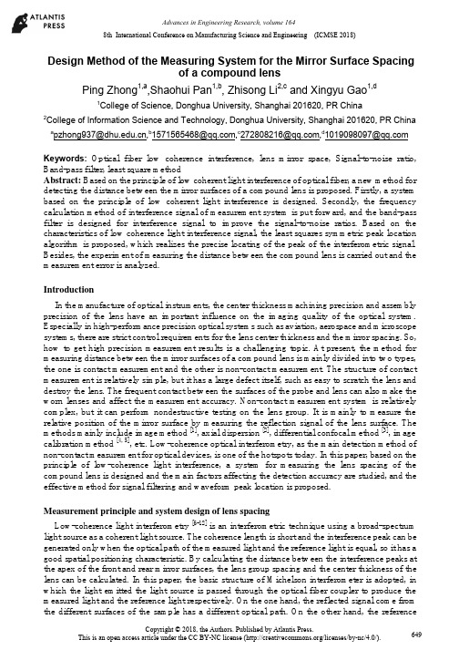
8th International Conference on Manufacturing Science and Engineering (ICMSE 2018)Design Method of the Measuring System for the Mirror Surface Spacingof a compound lensPing Zhong1,a,Shaohui Pan1,b, Zhisong Li2,c and Xingyu Gao1,d1College of Science, Donghua University, Shanghai 201620, PR China2College of Information Science and Technology, Donghua University, Shanghai 201620, PR China a b*****************,c****************,d*****************Keywords:Optical fiber low coherence interference, lens mirror space, Signal-to-noise ratio, Band-pass filter, least square methodAbstract:Based on the principle of low coherent light interference of optical fiber, a new method for detecting the distance between the mirror surfaces of a compound lens is proposed. Firstly, a system based on the principle of low coherent light interference is designed. Secondly, the frequency calculation method of interference signal of measurement system is put forward, and the band-pass filter is designed for interference signal to improve the signal-to-noise ratios. Based on the characteristics of low coherence light interference signal, the least squares symmetric peak location algorithm is proposed, which realizes the precise locating of the peak of the interferometric signal. Besides, the experiment of measuring the distance between the compound lens is carried out and the measurement error is analyzed.IntroductionIn the manufacture of optical instruments, the center thickness machining precision and assembly precision of the lens have an important influence on the imaging quality of the optical system. Especially in high-performance precision optical systems such as aviation, aerospace and microscope systems, there are strict control requirements for the lens center thickness and the mirror spacing. So, how to get high precision measurement results is a challenging topic. At present, the method for measuring distance between the mirror surfaces of a compound lens is mainly divided into two types, the one is contact measurement and the other is non-contact measurement. The structure of contact measurement is relatively simple, but it has a large defect itself, such as easy to scratch the lens and destroy the lens. The frequent contact between the surfaces of the probe and lens can also make the worn lenses and affect the measurement accuracy. Non-contact measurement system is relatively complex, but it can perform nondestructive testing on the lens group. It is mainly to measure the relative position of the mirror surface by measuring the reflection signal of the lens surface. The methods mainly include image method [1], axial dispersion [2], differential confocal method [3], image calibration method [4, 5], etc. Low-coherence optical interferometry, as the main detection method of non-contact measurement for optical devices, is one of the hotspots today. In this paper, based on the principle of low-coherence light interference, a system for measuring the lens spacing of the compound lens is designed and the main factors affecting the detection accuracy are studied, and the effective method for signal filtering and waveform peak location is proposed.Measurement principle and system design of lens spacingLow-coherence light interferometry [6-12] is an interferometric technique using a broad-spectrum light source as a coherent light source. The coherence length is short and the interference peak can be generated only when the optical path of the measured light and the reference light is equal, so it has a good spatial positioning characteristic. By calculating the distance between the interference peaks at the apex of the front and rear mirror surfaces, the lens group spacing and the center thickness of the lens can be calculated. In this paper, the basic structure of Michelson interferometer is adopted, in which the light emitted the light source is passed through the optical fiber coupler to produce the measured light and the reference light respectively. On the one hand, the reflected signal come from the different surfaces of the sample has a different optical path. On the other hand, the referenceCopyright © 2018, the Authors. Published by Atlantis Press.This is an open access article under the CC BY-NC license (/licenses/by-nc/4.0/). 649optical path will change with the position of the reference mirror. Only the reflected signal from a specific location of the sample can be coherent with the reference light, where the location of the maximum intensity of coherent signal corresponds to the equal optical path position. The structure of the lens spacing measurement system is designed as shown in Fig.1.Fig.1. Lens group spacing detection system diagramThe light emitted from the wide-spectrum light source SLD (center wavelength 1310 nm, half-wave width 85 nm) is split by the fiber coupler and then enters the circulator 1 and the circulator 2, and forms measurement light and reference light, respectively. In order to facilitate the installation and debug the detection system, the visible light with the wavelength of 660nm and the measured light are mixed in the wavelength division multiplexer, and then, they are projected onto the front and back surfaces of the lens group by the collimator and reflected by the front and back surfaces of the lenses in the compound lens. Finally, the reflected light is shot into the ring through the collimator and the wavelength division multiplexer and recoupled into the optical fiber system from the port 3. In the same way, the reference light is reflected by a movable plane reflector. The returned reference light is ejected through port 3 of the ring and interferes with the measured light in the optical fiber coupler. The returned reference light is ejected through port 3 of the ring and interferes with the measured light in the optical fiber coupler. The path of the reference light can be changed by driving a plane reflector to move uniformly in a straight line. When the optical path of the measured light is equal to that of the reference light, that is, when the optical path difference is zero, the interference signal is strongest, at this time the maximum wave peak signal can be detected by the computer.Since the measuring beam contains many light rays reflected from the front and rear surfaces of multiple lenses, there will be multiple sets of maximum wave peaks in the process of moving plane reflector. According to the relative position of two zero light path difference, the measurement of lens spacing of compound lens can be completed. In the process of measurement, the information of the plane reflector is recorded in real time by a high resolution grating scale displacement sensor. In order to suppress the common-mode noise of the system and improve the signal-to-noise ratio of the system as much as possible, the system proposed in this paper uses a balanced detector for the photoelectric conversion of the interference signal. Then the data acquisition card is controlled by the computer, and the signal is processed by the computer. In order to further suppress the noise, a signal filter is designed.Signal filtering and waveform peak locationDesign of band-pass filterIn the detection system, the intensity of reflected light of the plane mirror is higher than the intensity of the tested lens. When the intensity ratio of the incident light passing through the reference light and detection light is 50:50, the interference signal is very weak. Fig.2(a) shows the waveform of the interference signals. In this case, the peaks of interference signals are difficult to extract. Through experiments, we can set the intensity ratio of the incident light passing through the reference light and detection light as 80: 20, and the output interference signals are very obvious as shown inFig.2(b).650Fig.2. The comparison of interference signal intensity.(a) the waveform of the interference signals while theintensity ratio is 50:50; (b) the waveform of the interference signals while the intensity ratio is 80:20It can be seen from Fig.2 (b) that, although the strong contrast interference signal can be obtained by setting the light intensity ratio between the reference light and detection light, the interference signal are often mixed with noise, which directly affects the location of peak signal. In this paper, a band-pass filter is designed to suppress the noise signal and improve the signal-to-noise ratio [13,14].The center wavelength of the designed filter can be calculated. Assuming that the moving speed of the plane mirror on a guide rail is mm/s during detection process and the center wavelength of the broadband light source is λ nm, then the center wavelength ( f ) of the filter can be calculated by the Eq.(1):=(2 ∕ )×10 . (1)For the system designed in this paper, v is 3.78mm/s , the wavelength rang of the broadband light source is 1290∼1330 nm, λ is 1310nm , thus the f =5.77×10 kHz and the frequency range of a band-pass filter is from 4.77kHz to 6.77kHz , and the center frequency can be selected as 5.77kHz .Method for locating the peak of interference signalIn this paper, the location of the peak of interference signal is the key to detection of lens spacing and can be determined by extracting the signal envelope. According` to the principle of low coherence interference, the wave peak of interference signal represents the interference generation between the reference light and detection light at zero optical paths. For measuring system, as long as the optical path difference between the two peaks of the interferometric signal from the lens group is obtained, the distance between the lenses of compound lens can be obtained. A simple method is to use the peak signal to determine the location of the zero optical path difference. However, because the adjacent extreme signals are so close to each other, the noise introduced in the detection process can easily cause location error which will lead to poor repeatability accuracy of the measurement system. The Gauss fitting algorithm has the advantage of locating peaks, but it requires that the interference signal has good symmetry. So it cannot meet the requirements of the system designed in this paper. In this paper, a symmetric peak location algorithm based on the least square method is proposed.First, the acquired interference signals are preprocess. Fig.3(a) shows the primary signals collected. The position of the mean value of the intensity is set to the abscissa axis. Fig.3(b) shows the sum of the absolute values for the same position signals. The envelope image of the signals is represented by a dotted line shown in Fig.3(b).According to the theory of partial coherence, when the value of function of the location points in envelope curve is greater than 1/e of the maximum value, these points are directly related to the coherence length of the light source. So the signals whose value is greater than 1/e of the maximum value point are selected as an effective processing signal, and then the location of peak signal can bedetermined by the a symmetric peak location algorithm based on least square. 651Fig.3. The method of locating signal peak.(a) The primary signals collected; (b) Envelope image of signal The method can be described as follows: i) Firstly, all points whose values are greater than 1/e of the maximum are selected, and then these points are plotted as a curve which called the original curve, it can be seen in Fig.4(a). After that, a symmetry axis which is parallel to the vertical axis and passes through the maximum value point of the original curve is drawn, then, the original curve revolves around the symmetry axis and forms another curve which is called revolved curve. ii) The revolved curve is moved left or right along the horizontal axis. Meanwhile, the mean square error between the original curve and the revolved curve is calculated. When the mean square error obtained is the smallest, the best translational position to the revolved curve is determined. iii) The revolved curve was moved according to the translation amount, as shown in Fig.4(b). Finally, the symmetrical position of the two curves is used as the zero-path difference position. The method utilizes the least squares method can equalize the errors brought by the interference signals and the measurement error and the system error can be effectively reduced.Fig.4. The method of locating wave crests.(a) Flip chart; (b) Flipping the curve after translationSpecular distance measurement experiment and error analysisAccording to the design principle of lens spacing detection system, a measurement system is set up as shown in Fig.5. Among them, the center wavelength of the detection system is 1310nm, and the half wavelength width of the SLD wide spectrum light source is 85nm, and its optical power is 10.8mW.Fig.5 Measurement test system for detecting the distance between the mirror surfaces of a compound lens (1) a wave division multiplexer, (2) Circulator 1, (3) 80/20 fiber couplers, (4) Circulator 2, (5) 50/50 opticalcouplers, (6) the single mode fiber , (7) balance detector652In order to test the measurement accuracy of the system designed in this article, an achromatic composite lens group is selected to perform experiment for detecting distance between the mirror surfaces. Among them, the compound lens includes 7 groups of lenses, and the structure of the combined lens is shown in Fig.6.Fig.6 The structure of the lens group to be measuredAccording to the experimental system and the detection algorithm, the measurement of the lens spacing of the compound lens is carried out. The interference signal improvement is very obvious, and the output interference signal waveform was shown in Fig.7(a), and Fig.7(b) is the waveform of the interference signal after filtered.Fig.7 Measurement of the waveforms of the interferometric signal in the lens group, (a) the waveforms of theinterfering signal before filtering,(b) the waveforms of the interfering signal after filteringIn order to evaluate the accuracy and stability of the test system, the lens group has been measured for many times. Table.1 lists the design values of the measured lenses, the average values of the ten measurements and the standard deviation calculated.Table.1 Measurement data of spacing thickness of lens groupSampleDesign thickness or spacing[mm] The mean value of measuring thickness or spacing [mm] Standard deviation[nm] Lens 15 .00 5.0327 59 Air gap 1-26.00 6.0155 101 Lens 25.00 4.9879 127 Air gap 2-35.00 5.0214 167 Lens 36.00 5.9897 201 Air gap 3-45.90 5.8591 221 Lens 46.00 6.0319 260 Air gap 4-58.00 7.9981 239 Lens 55.00 4.9794 327 Air gap 5-618.00 17.8951 389 Lens 65.00 5.0124 372 Air gap 6-77.00 6.9978 408 Lens 77.00 7.0214425 653According to the results of the measurement data, it can be seen that the relative intensity of the reflected light on the lens surface at the rear end of the lens group is weak and the standard deviation of measurement is relatively large due to the influence of the number of lenses contained a compound lens and the reflection loss of the lens surface. With the increase of the number of lens to be measured, the interference signal gradually get weakened and the precise of the positioning accuracy of the zero optical path difference position be reduced,which will lead to an increase in the measurement standard deviation in measuring the lens spacing of the compound lens.ConclusionIn this paper, based on the low coherent light interference method, a system for measuring the lens spacing of the compound lens is designed. A calculation method of interference signal frequency in measurement system is put forward, and a bandpass filter is designed, which can effectively improve the signal-to-noise ratio of the interferometric signal. The fitting method of the interference signal envelope is proposed. Based on the characteristics of the low-coherence interference signal, we used a least-squares correction information positioning method, which effectively improves the repeatability of the measurement. Finally, by testing the lens spacing of the combined lens, the effectiveness of the proposed design method is proved. The detection system not only is convenient, fast, and has no damage to optical devices, but also has high precision and strong stability. It has a good application prospect in optical processing and optical detection.AcknowledgementsThis work is supported by the National Natural Science Foundation of China (Grant No.51575099)References[1] A.V. Goncharov, L.L. Bailon and N.M. Devaney. Spie:Vol.7389(2009),p.738912.[2] M. Kunkel, J. Schulze. Glass Science and Technology: Vol.78(2005),p.245.[3] L.B. Shi, L.R. Qiu and Y. Wang. Chinese Journal of Scientific Instrument :Vol. 33(2012),p. 683.[4] H.W. Gao, H. Wang, Y.Y. Liu and Y. Yu. Journal of Electronic Measurement and Instrument:Vol.31(2017),p.820.[5] J.H. Zhang, Q Liu and R.H. Nie.Spie:Vol.36(2016),p.174.[6] P. Langehanenberg,A. Ruprecht. Spie:Vol.8844(2013),p.88444F.[7] J. Benitez, J. Mora.IEEE Photonics Technology Letters:Vol.29(2017),p.1735.[8] S. Merlo, P. Poma and E. Crisa. Sensors:Vol.17(2017).[9] O. Martinez-Matos, C. Rickenstorff and S. Zamora. Optics Express:Vol.25(2017),p.3222.[10] R. Abuter, M. Accardo and A .Amorim. Astronomy & Astrophysics:Vol.602(2017).[11] R.W Kunze, R. Schmitt. Tm-Technisches Messen:Vol.84(2017),p.575.[12] K.Li, M. Jiang, Z.Z. Zhao and Z.M.Wang. Optics Communications:Vol.389(2017),p.234.[13] J.M.Tang, H.W. Liu, Q.F. Zhang, B.P. Ren and Y.H. Liu. IEEE Transactions on AppliedSuperconductivity:Vol.28(2018).[14] H Lu, Z.Q. Yue and J.L. Zhao. Optics Communications:Vol.414(2018).654。
非球面光学元件面型检测技术研究进展与最新应用

非球面光学元件面型检测技术研究进展与最新应用梁子健 杨甬英 赵宏洋 刘圣安Advances in research and applications of optical aspheric surface metrologyLIANG Zi-jian, YANG Yong-ying, ZHAO Hong-yang, LIU Sheng-an引用本文:梁子健,杨甬英,赵宏洋,刘圣安. 非球面光学元件面型检测技术研究进展与最新应用[J]. 中国光学, 2022, 15(2): 161-186. doi: 10.37188/CO.2021-0143LIANG Zi-jian, YANG Yong-ying, ZHAO Hong-yang, LIU Sheng-an. Advances in research and applications of optical aspheric surface metrology[J]. Chinese Optics, 2022, 15(2): 161-186. doi: 10.37188/CO.2021-0143在线阅读 View online: https:///10.37188/CO.2021-0143您可能感兴趣的其他文章Articles you may be interested in非零位凸非球面子孔径拼接检测技术研究Research on non-null convex aspherical sub-aperture stitching detection technology中国光学. 2018, 11(5): 798 https:///10.3788/CO.20181105.0798光学自由曲面面形检测技术Optical free-form surfaces testing technologies中国光学. 2017, 10(3): 283 https:///10.3788/CO.20171003.0283大偏离度非球面检测畸变校正方法Distortion correcting method when testing large-departure asphere中国光学. 2017, 10(3): 383 https:///10.3788/CO.20171003.0383一种针对超大口径凸非球面的面形检测方法Surface testing method for ultra-large convex aspheric surfaces中国光学. 2019, 12(5): 1147 https:///10.3788/CO.20191205.1147易测量非球面定义及应用Definition and application of easily measurable aspheric surfaces中国光学. 2017, 10(2): 256 https:///10.3788/CO.20171002.0256点衍射干涉检测技术Point diffraction in terference detection technology中国光学. 2017, 10(4): 391 https:///10.3788/CO.20171004.0391第 15 卷 第 2 期中国光学Vol. 15 No. 2 2022年3月Chinese Optics Mar. 2022文章编号 2095-1531(2022)02-0161-26非球面光学元件面型检测技术研究进展与最新应用梁子健,杨甬英*,赵宏洋,刘圣安(浙江大学 现代光学仪器国家重点实验室,浙江 杭州 310027)摘要:非球面光学元件,特别是其中的自由曲面元件,在设计自由度上相比于球面具有很大的优势,基于非球面构建的光学系统能够以简单的光机结构实现复杂的设计目的。
Sirius眼前节分析系统与A型超声测厚仪对中央角膜厚度测量结果的对照分析

Sirius眼前节分析系统与A型超声测厚仪对中央角膜厚度测量结果的对照分析邱乐梅;王顺清;张小兰;孙成淑;邓应平【摘要】目的对照分析Sirius眼前节分析系统和A型超声测厚仪对中央角膜厚度(CCT)测量结果的差异,研究Sirius系统的准确性和可靠性.方法随机抽取屈光手术前175例(175只眼),分别应用Sirius(意大利科以康)和A超(DGH500)进行CCT测量,用SPSS13.0进行配对t检验.结果 Sirius系统测量的CCT平均值为(534.75±33.757)μm,A超所测CCT平均值为(550.70±35.037) μm.A超比Sirius 测量的CCT厚15.95 μm,有统计学差异(P<0.01),相关分析显示两种方法呈正相关(r =0.954,P=0.00).因Sirius测量不受操作者影响且样本量较大,便以Sirius所测CCT分3组(1组CCT <500 μm,2组CCT500~550 μm,3组CCT >550μm),3组结果均为A超比Sirus测量的CCT厚,但都有很好的相关性.1组Sirius系统和A 超的CCT分别为(478.96±13.408)μm和(496.70±20.003)μm,r1=0.823,P=0.000;2组分别为(524.49±14.031) μm和(540.08±16.981)μm,r2 =0.794,P=0.000;3组分别为(571.08±15.769)μm和(586.90±18.952)μm,r3 =0.839,P=0.000.结论用Sirius三维地形图、眼前节分析系统进行屈光手术术前CCT测量,其结果可靠性好、影响因素少且操作简单、无创,具有很好的临床应用价值.%Objective To compare the difference of central comeal thickness(CCT) between Sinus anterior system with A ultrasonic pachymetry and disuss the precision and reliability of Sirius anterior system. Methods The CCT was measured by Sirius (Italia COS) and A ultrasonic pacbymetry (DGH550) in random sample composed of 175 eyes before refraction surgery. SPSS 13.0 and EXCEL were used for paired-samples T test. Results The mean CCT values were [534.75 ±33.757) μm measured by Sirius anterior system and (550.70 ±35.037 ) urn measured by A ultrasonic pacbymetry. Compared with Sirius anterior system, A ultrasonic pachymetry overestimated the CCT by a mean of 15.95 μm. There was aignificant difference ( P <0.01). Results from the two apparatuses were in linear correlation ( r =0.954 , P =0. 00). Because the CCT values obtruded with Sirius anterior system do not affected by operactars influence, we divided these values into three group ( groupl CCT <500 μm:group2 500 -550μm:group3 CCT >550 μm). The results tested by A ultrasonic pachymetry in all three group showed higher values than that obtained with Sirius anterion system and showed high correlation. IN groupl, the CCT values tested by Sirius anterior system and A ultrasonic pachymetry are (478.96 ±13.408) μm and (496.70±20.003)μm , rl =0.823,P =0.000: In group2, the valuse are (524.49 ±14.031 )μm and (540.08 ±16.981 )μm,r2 =0.794, P =0.000: In group3,tbe values are (571.08 ±15.769)μm and (586.90 ±18.952)μm, r3 =0.839, P =0.000. Conclusion CCT measured by Sirius anterior system before refraction surgery was reliable and easily applied with no tissue damage that showed great clinical value.【期刊名称】《临床眼科杂志》【年(卷),期】2012(020)003【总页数】3页(P202-204)【关键词】Sirius系统;A超测厚仪;中央角膜厚度【作者】邱乐梅;王顺清;张小兰;孙成淑;邓应平【作者单位】610041成都,四川大学华西医院眼科;610041成都,四川大学华西医院眼科;610041成都,四川大学华西医院眼科;610041成都,四川大学华西医院眼科;610041成都,四川大学华西医院眼科【正文语种】中文屈光手术中以准分子激光手术开展最为普遍,而中央角膜厚度在术前手术方式选择、术后安全的预测以及并发症的预防具有重要意义。
- 1、下载文档前请自行甄别文档内容的完整性,平台不提供额外的编辑、内容补充、找答案等附加服务。
- 2、"仅部分预览"的文档,不可在线预览部分如存在完整性等问题,可反馈申请退款(可完整预览的文档不适用该条件!)。
- 3、如文档侵犯您的权益,请联系客服反馈,我们会尽快为您处理(人工客服工作时间:9:00-18:30)。
field guide to interferometric optical testing
摘要:
I.引言
- 光学测试的重要性
- 干涉测量技术的背景
II.干涉测量技术的基本原理
- 波的叠加原理
- 相干光源与干涉仪
- 干涉图样的形成
III.干涉测量技术的应用领域
- 表面检测与测量
- 光学元件的检测与校准
- 光纤通信与光网络
- 生物医学成像
IV.干涉测量技术的最新发展
- 数字干涉测量技术
- 频率域干涉测量技术
- 空间域干涉测量技术
V.干涉测量技术的挑战与展望
- 技术挑战与发展趋势
- 应用领域的拓展
- 我国在干涉测量技术的研究现状与展望
正文:
干涉测量技术是一种基于光的波动性质进行测量的方法,广泛应用于光学、光电子学、光纤通信等领域。
它具有高精度、高灵敏度、非接触测量等优点,对于提高产品质量、推动科技进步具有重要意义。
本文将介绍干涉测量技术的基本原理、应用领域、最新发展及挑战与展望。
首先,我们来了解干涉测量技术的基本原理。
干涉测量是基于波的叠加原理,通过将同一光源发出的两束光波相互叠加,形成干涉图样。
干涉图样包含了光学系统各元件的物理特性信息,通过对其进行分析,可以获得系统的相关参数。
而干涉仪则是实现干涉测量的核心装置,它可以分为相干光源、分光镜、反射镜、观察屏等部分。
在干涉测量过程中,相干光源发出的光束经过分光镜分为两束,一束光照射到待测物体,另一束光照射到参考镜。
两束光在反射后重新汇合,并在观察屏上形成干涉图样。
干涉测量技术在许多领域都有广泛的应用。
在表面检测与测量领域,干涉测量技术可以实现对表面粗糙度、膜层厚度等参数的高精度测量。
在光学元件的检测与校准领域,干涉测量技术可以用于检测光学元件的表面质量、光学系统像差等,从而保证光学系统的性能。
此外,在光纤通信与光网络、生物医学成像等领域,干涉测量技术也发挥着重要作用。
近年来,干涉测量技术不断取得突破性进展。
数字干涉测量技术利用数字信号处理技术对干涉图样进行处理,提高了测量精度和速度。
频率域干涉测量技术通过测量光的频率变化来获取干涉信息,提高了干涉测量的灵敏度。
空间域干涉测量技术则通过在多个空间位置同时进行干涉测量,实现了对光学系统
空间特性的检测。
尽管干涉测量技术取得了显著进展,但仍面临着一些挑战。
例如,提高测量精度和灵敏度、拓展应用领域、减小仪器体积等。
在未来,干涉测量技术将继续朝着更精确、更灵敏、更智能的方向发展。
同时,随着科技的不断进步,干涉测量技术在各个领域的应用也将得到进一步拓展。