海卓CV-100自动切换说明书中文版
MiCOM P12y使用说明书

在可翻开的下盖板的下面,有一个电池舱,可使用½AA 型电池。该电池可作
为后备电源,保存保护装置存储器中的事件记录,故障记录和故障录波(仅对
P126 和 P127)。盖板下还有一个 9 针的母 D 型前部通讯端口。它的作用是通过
RS232 串行数据连接(SK1 口),在本地实现 PC 机和保护装置的通讯(最长距离
且跳闸原因也被复位后,指示灯熄
灭。
警告指示灯(L3:桔黄色 LED 指示灯,标注为 Warning):
灯亮表示 MiCOM P12y 保护装置有内部警告。当检测到一个“非严重”的内部 警告时,该指示灯将持续闪烁。只有当导致内部警告的原因不存在了(修理模块,故 障消失等),指示灯才会熄灭。
辅助电源(L4:绿色 LED 指示灯,标注为 Aux. Supply):
灯亮表示 MiCOM P12y 保护装置工作正常,装置电源的辅助电源存在。
可自由编程的指示灯(L5 to L8:标签自由标注):
这些 LED 指示灯可以由用户以提供的门槛(瞬动和延时信号)信息为基础自由 编程。用户选择他想用指示灯看到的信号,通过菜单将它们分配到每一个 LED 指示 灯上(用逻辑 OR)。当相关信号启动时,对应的指示灯亮。当相应的报警被确认了 之后,指示灯熄灭。
第 3 页/共 24 页 使用说明书
21 21 21 21 21 22 22 23 23 23 24 24 24
上海阿海珐电力自动化有限公司 MiCOMP12y 系列
第 4 页/共 24 页 使用说明书
1. 装置介绍
MiCOM P125、P126、P127 系列保护装置是法国 AREVA 公司继 K 系列、 MODN 系列以及 MX3 系列产品获得成功后新研制的换代产品。所设计的 MiCOM P125、 P126、P127 保护装置具有保护、控制和监视等多重功能,适用于工业, 配电网络和变电站中,可作为变压器和发电机变压器保护方案的一部分以及为高压 和超高压输电系统提供后备保护等。
海卓公司 CS-110 系列自动切换系统操作维护手册说明书

CS-110CS-110 Rev. 4/22/15这份海卓公司文件以英文版Instruction pages(CS-110)为准。
本翻译版本仅是为用户提供方便所有海卓公司的产品说明书都能在海卓公司的网站www.instruments.com找到翻译免责声明操作维护手册自 动 切 换 系 统104、主屏幕布局......... (3)I. (3)II. (5)III. (7)IV............................................................................................................................................................................................................ 4 .. (6)............................................................................ 8 .. (9)海卓公司CS-110系列自动切换系统目录安全信息概述1、内容2、一般规格3、功能概述安装说明1、电气连接2、概述1、按键操作2、LED显示说明3、基本操作4、Modbus通讯操作说明维护图示1、典型的系统安装图2、CS-110内部接线图3、CS-110显示屏流程图显示屏将会显示日期、时间、每组氯瓶的工作时间(电动球阀的开启时间)及(可选的)将显示系统的操作情况。
2个4-20mA输入通道可接收电子秤的信号,此功能是可选功能。
控制器接收两个压力开关信号,并提供控制信号对电动球阀进行操作。
LED和LCD指示灯功能介绍:外形尺寸:板和电源的任何部分。
电气:电路板和电路线都可能引起电击或电路,在确认电源已经断开之前,请不要触摸电路总述:在操作此设备之前,确保遵循所有的安全警示。
海洋矩阵OMX-07HMHM0004 HDMI 4x1 切换器说明书
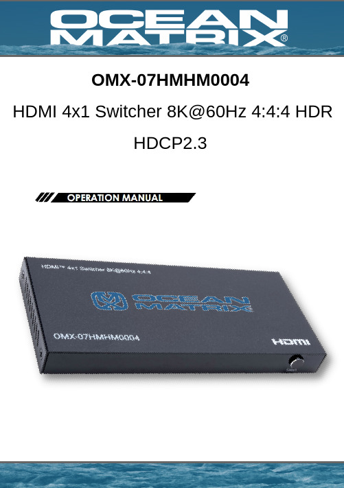
OMX-07HMHM0004HDMI 4x1 Switcher 8K@60Hz 4:4:4 HDRHDCP2.3Description:The Ocean Matrix OMX-07HMHM0004 is an HDMI 4x1 switcher that lets you share four HDMI-enabled video sources with a single display or projector. The switcher features four independent inputs that each support 8K resolutions and 7.1 surround sound audio. The switcher is backward compatible with Ultra HD 4K and HD 1080p, so users can be assured that their digital signage will look great in all situations.Features:Supports Resolutions up to 8K@60Hz 4:4:4, 4K@120Hz, and 1080p@240Hz1200MHz/12Gbps per Channel Bandwidth (48Gbps All Channels)Supports 12bit per Channel (36bit All Channels) Deep ColorHDCP 2.3, HDCP2.2 and HDCP1.4 CompliantSupport High Dynamic Range (HDR) Video Pass-through, such asHDR10/HDR10+/Dolby vision etc.VRR (Variable Refresh Rate), ALLM (Auto Low-latency Mode), and QFT (Quick Frame Transport) FunctionalityBuilt-in Equalizer, Retiming, and DriverAutomatic, Manual, and Remote Control Switching SupportedSupports Uncompressed Audio; LPCMSupports Compressed Audio: DTS, Dolby Digital (DTS-HD Master Audio™ andDolby TrueHD)Specifications:Input Ports: HDMI x 4Output Ports: HDMI x 1Vertical Frequency Range: 50/60/100/120/240HzVideo Amplifier Bandwidth: 12Gbps/1200MHz per Channel (48Gbps All Channels) Interlaced (50 & 60Hz): 480i,576i,1080iProgressive (50 & 60Hz): 480p,576p,720p,1080p,4K@24/30Hz,4K@50/60/120Hz, 8K@24/30/50/60HzOperating Temperature: 32°F – 158°F (0°C-70°C)Storage Humidity: 5% to 90% TH Non-condensationPower Consumption (Max): 5WSwitcher Unit & Power Supply Certifications: FCC, CE, RoHSDimensions (LxWxH): 5.35 x 2.41 x 0.56in (136.3 x 61.5 x 14.5mm)Operation Controls and Functions:245789Power LED IndicatorInput Ports 1-4 LED Indicators - Blue LED indicates an active signal path while noLED indicates no input signalAuto Mode LED Indicator - LED on indicates the unit is in automatic switchingmode while off indicates it's in manual switching modeIR Mode LED Indicator - LED on indicates the unit is in the normal IR receivermode while off indicates it's not in IR function modeIR Signal Receiver PortSwitch - Press to change the input channel, automatic / manual switching mode,and IR receiver modeDC/5V - DC 5V input via micro-USBHDMI Output Port1.2.3.4.5.6.7.8.316Item Includes:Remote Control:Power Button1-4 - Press the number to select the input source accordinglyIR - Press to turn on/off the IR receiver functionUSB Power Cable1. a.b.c.2.Connection DiagramThe unit should be serviced by qualified service personnel if: (a) The DC power supply cord or AC adaptor has been damaged (b) Objects or liquids have gotten into the unit (c) The unit has been exposed to rain (d) The unit does not operate normally or exhibits a marked change in performance; The unit has been dropped or the cabinet is damaged. (2) Servicing Personnel: Do not attempt to service the unit beyond that described in these operating instructions. Refer all other servicing to authorized servicing personnel. (3) Replacement parts: When parts need replacing ensure the servicer uses parts specified by the manufacturer. Unauthorized substitutes may result in fire, electric shock, or other hazards. (4) Safety check: After repairs or service, ask the servicer to perform safety checks to confirm that the unit is in proper working condition.Damage requiring service:PRODUCT SERVICEAlways follow basic safety precautions to reduce the risk of fire, electrical shock and injury to persons.To prevent fire or shock hazard, do not expose the unit to rain, moisture or install this product near water.Never spill liquid of any kind on or into this product.Never push an object of any kind into this product through any openings or empty slots in the unit, as you may damage parts inside the unit.Do not attach the power supply cabling to building surfaces.Use only the supplied power supply unit (PSU). Do not use the PSU if it is damaged.Do not allow anything to rest on the power cabling or allow any weight to be placed upon it or any person walk on it.To protect the unit from overheating, do not block any vents or openings in the unit housing that provide ventilation and allow for sufficient space for air to circulate around the unitPlease read all instructions before attempting to unpack, install or operate this equipment and before connecting the power supply.Please keep the following in mind as you unpack and install the unit:SAFETY PRECAUTIONSWARRANTY1 Year。
ZS-100自动枕式包装机操作说明书(中文版)
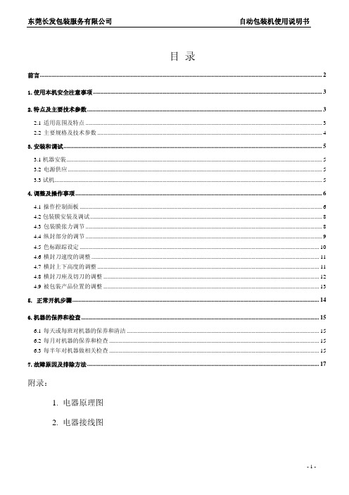
目 录前言 (2)1.使用本机安全注意事项 (3)2.特点及主要技术参数 (3)2.1适用范围及特点 (3)2.2主要规格及技术参数 (4)3.安装和调试 (5)3.1机器安装 (5)3.2电源供应 (5)3.3试机 (5)4.调整及操作事项 (6)4.1操作控制面板 (6)4.2包装膜安装及调试 (8)4.3包装膜张力调节 (8)4.4纵封部分的调节 (9)4.5色标跟踪设定 (10)4.6横封刀速度的调整 (11)4.7横封上下高度的调整 (11)4.8横封刀座及切刀的调整 (12)4.9被包装产品位置的调整 (13)5. 正常开机步骤 (14)6.机器的保养和检查 (15)6.1每天或每班对机器的保养和清洁 (15)6.2每月对机器的保养和检查 (15)6.3每半年对机器做相关检查 (15)7.故障原因及排除方法 (17)附录:1. 电器原理图2. 电器接线图前言感谢您选用欧华包装设备有限公司设计制造的高速枕式自动包装机,产品具有结构合理、性能优越、外形美观、坚固耐用和安全可靠等优点,它的使用,将为您的工作提供最大的便利。
在安装、使用包装机之前,请务必熟悉本《使用说明书》的各项内容,它将帮助您了解包装机的基本性能、结构、操作及维护方法,帮助您如何正确使用机器,使它发挥最佳性能,减少故障,延长使用寿命。
试机期间,操作人员应在本公司职员的指导下操作,尽快掌握本机器的使用。
注:由于我公司的包装机不断改进,有关信息恕不另行通知,敬请谅解!1.使用本机安全注意事项1.1 每次开机前,要检查工作台面、输送带、横封刀座上一定不能有工具或任何杂物,观察机器周围有无异常;1.2 每次开机前,防护装置应处于功能位置!1.3 机器在运转当中,严禁身体任何部位靠近或接触运转部件!1.4 机器在运转当中,严禁将手和工具伸进横封刀座内!1.5 机器在正常工作时,严禁频繁切换操作按钮,严禁随意频繁更改参数设定值;1.6 严禁超高速长时间运行;1.7 禁止二人以上同时操作机器的各类开关按钮和机构;维修和保养时应切断电源;多人同时调试、维修机器时,要注意相互沟通和协调,防止因不协调而造成事故;1.8 检查、维修电气控制电路时,严禁带电工作!一定要切断电源!要由电气专业人士来完成;1.9 操作人员因饮酒或疲劳不能保持清醒时,严禁进行操作、调试或维修工作;其他未经培训或不具备资格的人员不得操作机器;1.10 在未征得本公司同意之前严禁私自改动机器,不要在指定环境之外的条件下使用机器;1.11 本机在出厂时的绝缘电阻和接地电阻都符合国家安全标准,但第一次开机时或长期未使用,应开启加热器进行低温加热20分钟左右,以防止机器加热部分受潮。
CV-X100_IM_12803C_CN_1044-1
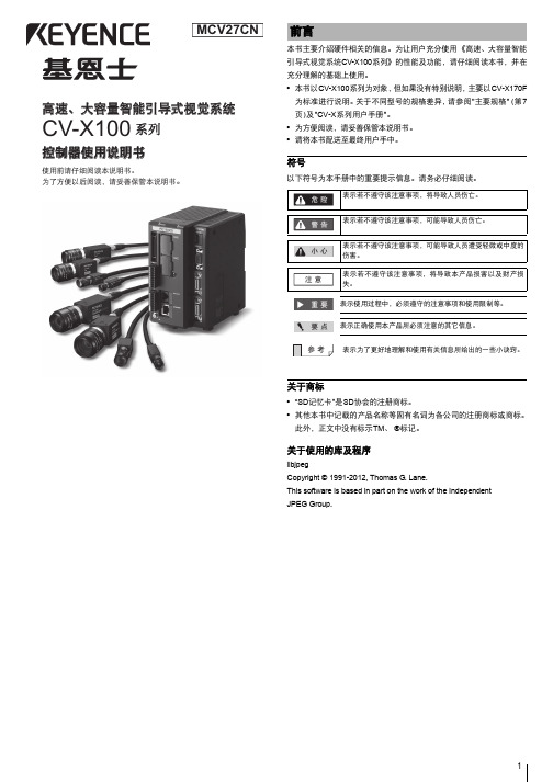
高速、大容量智能引导式视觉系统
CV-X100 系列
控制器使用说明书
使用前请仔细阅读本说明书。
为了方便以后阅读,请妥善保管本说明书。
前言
本书主要介绍硬件相关的信息。为让用户充分使用 《高速、大容量智能 引导式视觉系统CV-X100系列》的性能及功能,请仔细阅读本书,并在 充分理解的基础上使用。 • 本书以CV-X100系列为对象,但如果没有特别说明,主要以CV-X170F
4
1 将去除约7mm被膜的导线与7号端子 (24V DC)和8号端子 (0V)
连接后,把I/O端子台完全插入I/O连接器。
2 将接地线与接地端子连接。
连接接地线
注意
• 请与其他设备分别接地。 • 接地施工中请使用D型接地。 • 接地电阻请控制在100Ω以下。 • 请尽量缩短接地线。 • 无法分别接地时,请共用接地。但是,此时需使用相
关于本体的使用
注意
• 请勿用湿抹布、挥发油、稀释剂、酒精等擦拭。 • 请用抹布蘸取稀释的中性清洁剂,并在拧干后擦拭污垢,
再用柔软的干布擦拭干净。
规定及规格相关的注意事项
关于CE标识
本公司根据以下条件,确认本产品满足EC指令的必要事项。在EU各国 使用本产品时,请注意以下事项。
EMC指令(2004/108/EC) • 适用标准 EMI:EN61326-1, Class A
为标准进行说明。关于不同型号的规格差异,请参阅"主要规格" (第7 页)及"CV-X系列用户手册"。 • 为方便阅读,请妥善保管本说明书。 • 请将本书配送至最终用户手中。
符号
以下符号为本手册中的重要提示信息。请务必仔细阅读。
危 险 表示若不遵守该注意事项,将导致人员伤亡。
海利普变频器说明书C100

危险。 ● 请防止儿童或无关人员接近变频器。
1.2 送电中 危险
● 送电中绝不可插拔变频器上的任何连接器(操作面板除外),以 避免变频器损坏并造成人员伤亡。
1.3 运转中 注意
HLP-C10001D543
1.5 1.5 0.84
3×440-480V50/60HZ 5.1 3.4
3×380-440V50/60HZ 8.5 5.3
HLP-C10002D243
2.2 2.2 0.84
3×440-480V50/60HZ 7.3 4.8
2.3 产品技术规格
项目
规格
电压 输入 电源 频率
请用户严格遵照本说明书中的规定进行接线和操作,由于用户 没有仔细阅读说明书、 或未按照说明书的要求操作所引起的任何 直接或间接伤害及损失,海利普不承担任何责任,由错误操作方自 行承担。
HLP-C100系列使用说明书
系列
第2章 产品标准规格 2.1 产品铭牌说明
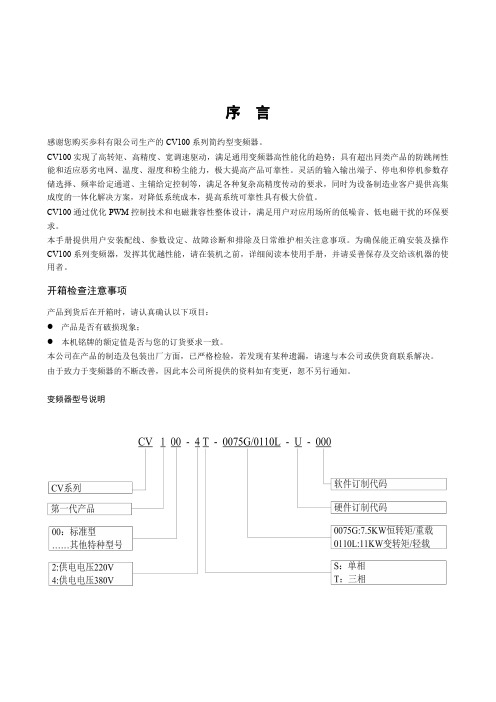
类型代码各位的意义如下:
1-8 9-12 13-14
2013-01版
HLP-C100系列
使用说明书
系列
前言
感谢选用HLP-C100系列高品质、高可靠性迷你型变频器。 在使用变频器前请详细阅读本使用说明书,以便正确安装和使用 变频器,充分发挥其功能,并确保安全。请妥善保存此说明书,以便日 后保养、维护、检修时使用。 变频器属于电力电子产品,为了您的安全,请务必由专业的电机工 程人员安装、调试。本手册中有 (注意)和 (危险) 等符号提 醒您在搬运、安装、运转、检查变频器时的安全防范事项,请您配合, 使变频器使用更加安全。若有疑虑,请与本公司或本公司各地的代理商 进行咨询,我们的专业人员乐于为您服务。 由于本公司产品升级,本说明书如有变动,恕不另行通知。
X100说明书
感谢您购买本公司记录仪,本机采用高性能低照度“cmos wxga hd ”高清感光芯片,有独特的超便携式设计,使它可以应用在各个领域,为您带来方便,安全,丰富多彩的日常生活。
主用于车载摄像,是行车中安全事故取证的最佳帮手。
在使用本产品之前,请详细阅读此用户手册,并请保管好此手册。
我们希望本产品,能满足您的需求并长期服务于您!本使用手册在编写和印刷中,可能存在一定文字错误,请谅解。
使用手册印刷过程中,机器因外观和软件的修复过程导致了同该使用手册的部分操作的非一致性,本公司保持最终解释权。
安装记录仪1.关闭引擎,将锁匙从点火器上取出。
2.将tf卡插入记录仪卡槽中。
3.将记录仪用支架垫黏贴安装在汽车的挡风玻璃上或驾驶仪表台上。
4.用电源线将记录仪的usb终端和汽车点烟器连接起来。
5.调整摄像位置,以便获取最佳的拍摄范围。
6.发动引擎,检查机器是否已安装正确。
【注意】(1)请在光线充足、全安的地方安装记录仪。
(2)当机器安装正确,其系统状态led会变成蓝色及显示屏会显示。
使用简介一.使用自动录像功能1.安装完毕后,启动汽车引擎,记录仪将会自动开启并开启自动录像功能。
2.关闭汽车引擎,在6秒后,记录仪保存档并将会关闭。
【注意】记录仪摄像镜头正/反相切换方法,长按【mic键】并保持3秒钟进行切换反相摄像。
长按【录像键】并保持3秒钟进行切换正相摄像,切换正或反相后,关机会自动保存其操作设置。
二.使用手动录像功能1.长按记录仪上的【开启/关闭键】并保持3秒钟。
2.当记录仪启动后,自动开启录像功能。
3.记录仪摄像镜头正/反相切换方法,长按【mic键】并保持3秒钟进行切换反相摄像。
长按【录像键】并保持3秒钟进行切换正相摄像。
(切换正或反相后,关机会自动保存设置)。
4.当再次点擎【录像键】,记录仪将会停止录像功能。
三.使用拍照功能1.长按记录仪上的【开启/关闭键】并保持3秒钟。
2.当记录仪启动后,在自动开启录像功能的状态下。
RAIS100操作手册中文版V1.0

操作手册 系统介绍
1.2.3 三面舵角指示单元 HLD-TRU100
三面舵角指示单元 HLD-TRU100 如图 4 所示。 三面舵角指示单元安装在驾驶室的天花板上,在互成 90 度的三个方向上均有 舵角指示,方便操作人员从不同方位观察舵角,其可视距离达到 5m 以上。 HLD-TRU100 本身提供旋钮调光功能,也可接受连接分配单元的控制实现统一调光 功能,同时可以与调光单元连接实现远程调光。
舵角指示系统涉及到的功能性能要求主要是指示精度、指针阻尼时间、刻度范 围几方面,IMO 对此有明确要求。
HLD-RAIS100 是一种全新设计的全数字化的舵角指示系统,它将舵角信息全部 转换为标准的 IEC61162-1(或 IEC61162-2)语句并在模块间进行传输,具有配置灵 活、指示精度高、反应快、照明效果好、调光灵活、外形小巧美观及安装维护简 单快捷等特点,并且全面符合 IMO 相关规范。
这个符号提示潜在的危险情况,如 果不能避免,可能会导致轻度或中度的 伤害以及财物损失。
这个符号提示不安全的操作,如果 不能避免,可能会导致财物损失或设备 故障。
必须严格遵守所有相关的安全规则和 标准!
维护和维修工作必须由经过专门培训、 熟悉电气设备的工程人员实施。
YAMAHA REV100 中文说明书

?
?秔 ??
75 短混响镶边 房间到镶边 短混响加入镶边及大音调变化效果 76 管风琴室 1 平面到镶边 镶边效果适合于管风琴音色 77 管风琴室 2 大厅到谐音 同上 79 谐音混响 2 人声加谐音 同上 81 镶边房间 2 平面加镶边 同上 83 滚动镶边 2 平面加镶边 同上
H 綜艧岾 ? ?现 1= 矻?
+?杄 縉
1、按下 STORE(储存)键不放,打开电源; 2、按上下箭头键选择所需初单个程序,若需全 部程序初始化,按上下箭头键直一显示块显示“——”即可; 3、再按一下 STORE(储存)键, 则 完 成 初 始 化 。
\F ? 梈 d 砳 o T& 謥姩鴹 ?
;
6
届 jD[v
混响/调制效果
J
z8 棂 ?~?
71 软镶边 1 大厅加镶边 将镶边与小音调变化,混响效果组合适合于垫类合成音色
靎 7 訵咽 % ?
峖 J; 鬨睶
73 环境镶边 1 房间到镶边 镶边效果加入短混响 74 环境镶边 2 房间到镶边 同上
j 涟 鱆妞
<"}od?7 柢
仦
嚛 偸玪 B
3、输出接口 QUTPUT:为 1/4in 拾音接口,可输出本机处理的音频信号,如果使用单声时, 只需接入一个该接口即可。
a 実蒢 q Q 蟹 d Q?嗬 俟 e 7
4、输入接口 INPUT:为 1/4in 拾音接口,可用来接入音频信号进行效果处理。单声时,只需 接入左 L-MONO 接口信号即可。
烾 E 矍[ 嬥 ? 題 +m ??
1、按上下箭头键使所需的程序号显示于块上;
&Q0??A 疅
2、选择一个编辑控制器,如 DELAY 延迟转动控制钮; 时,这个控制旁的显示灯亮; 4、听一个所编辑的效果。
EMX CHIME-100 电子铃声提示器说明书

CHIME-100™Auditory Alert SystemInstruction ManualThe CHIME-100 is an accessory device that produces a very loud audible notification when activated. Its maximum volume can exceed 100dBA at 5ft, which is easily heard even in environments with highbackground noise. It includes six selectable melodies, an easily adjustable volume, passthrough power outputs to run other peripherals, such as sensors or visual alert devices, an output relay, and an input which only requires a set of dry contacts for activation. Intended for indoor use only.Maximum volume in close proximities may exceed 100dBA, which can result in permanent hearing damage.When drilling, ensure no damage can be caused in desired mounting location, e.g. hidden wires, waterlines, etc.CHIME-100Auditory Alert AccessoryIncludes: CHIME-100, PG11 cable gland, and 9V Power Supply1.Power Jack2.Power LED3.Chime Select Button4.Volume Adjustment Knob5.Cable GripUnscrew the lid of the housing and carefully remove the lid.CAUTION: The lid and base are attached by the speaker’s wires.Excess force could damage the unit3.Mount the cable-grip in the large hole in the bottom of the housing by inserting it from the outside,then screwing on and tightening the nut from the inside.Presence LEDConfigure the CHIME-100 to play the desired melody by pressing the pushbutton on the side of the unit. Adjust the volume to a comfortable level. See section “Chime Adjustment”for more information.Reattach the lid to the base and screw down firmly. Test the setup again to ensure the correct chime plays at a comfortable listening level.VolumeTo adjust the volume of the CHIME-100, use the “Volume Adjustment Knob” sticking out of the housing’s side. See the table below.Volume AdjustmentChimeThe melody that is played when the input is activated can be changed by pressing the “Chime Select Button” on the side of the unit. Each time the button is pressed, the next melody is selected and played. There is a total of six different melody options. The selected melody will be remembered through power-down.InputsINPUT 1 & 2The CHIME-100 will activate when terminal INPUT 1 is shorted with terminal INPUT 2. The device used to short these terminals together can be anything that closes a circuit (e.g. relay contacts, transistor, light switch, pushbutton, etc).OutputsVOUTThe CHIME-100 comes with a 9VDC power adapter that plugs into the unit via barrel jack, and is powered through a wall outlet. This power supply can be used to power additional peripherals through the VOUT terminals. If using the included power adapter, the additional peripherals should draw no more than 400mA of current.RELAYA set of form C relay contacts (normally open, common, and normally closed), which can handle 2A, and 250VAC or 220VDC. This relay will switch states when INPUT1/INPUT2 activates the CHIME-100.NPNAn open collector transistor output will pull down to ground when activated. This output can handle160mA, and 100VDC. This transistor will switch states when INPUT1/INPUT2 activates the CHIME-100.WarrantyEMX Industries, Inc. products have a warranty against defects in materials and workmanship for a period of two years from date of sale to our customer.。
口袋卷边机 MB2001B 使用说明书

口袋卷边机Pocket Hemming Machine(MB2001B)使用说明书Instruction Manual常州智谷机电科技有限公司CHANGZHOU WISDOM &VALLEY ELECTRICAL TECHNOLOGY CO.,LTD在使用本设备之前请先阅读本使用说明书.Please read the operation manual of the touch screen interface before using the device 请将本使用说明书放在便于查阅的地方保管Please keep this operation manual of touch screen interface in convenient placeforreference2022.04.03版本信息/Version感谢购买IMB工业用缝纫机。
在使用此机器之前,请仔细阅读以下的说明,这样可以更好地帮到您了解此机器的相关操作。
这些说明是根据现行的条例明确阐述了正确的工作方法。
Thank you for purchasing this industrial sewing machine from IMBBefore using this automatic unit,please read the following instructions,which will help you tounderstand how the machine operates.These instructions illustrate the correct working methods to comply with current regulations.在没有得到IMB授权许可的前提下,此说明书的任何部分是不可以被复制或者转录的。
说明书的内容可能被修改,而不需预先通知。
No part of this manual may be copied or transcribed without requesting prior authorization from IMBThe contents of this manual may be subject to change without advance notification.我们将欣然接受各位提出的改进此说明书的任何建议和指示We are happy to receive suggestions and/or indications on ways we could improve this manual.本机介绍说明分为三部分,具体请参照《MB2001B-使用说明书》、《MB2001B-零件手册》、《MB2001B-触摸屏界面操作说明》。
YAMAHA REV100使用说明书

YAMAHA REV100使用说明书操作一、正确安装和连接YAMAHA--- REV100。
二、改变效果程序:YAMAHA—REV100共有99种效果程序,用上下光标键选择。
混响程序名类型说明01 Vocal rev1 人声适用于人声混响02 Vocal rev2 大厅 3号程序的前期延长,混响时间短 03 Vocal rev3 人声04 Room ambience1 盘子这些效果适用于鼓和打击乐音色,可作用于整个鼓组或某个鼓音色05 Room ambience206 Room ambience307 Wood booth1 人声08 Wood booth209 Acoustic piano plate 用于钢琴的混响 10 Club piano 大厅11 Booming kick1 用于底鼓的混响,强调低频12 Booming kick2 房间13 Loud snare 用于军鼓的混响14 Acoustec steel guitar1 盘子钢弦原声吉它的混响 15 Acoustec steel guitar2 16 String plate 弦乐的混响17 Acoustec gut guitar1 人声尼龙弦原声吉它混响 18 Acoustec gut guitar219 Btass room1 房间铜管乐器的混响20 Btass room立体声混响程序名类型说明21 Large hall1 大厅 Stage比hall的混响更明亮 22 Large hall223 Stage124 Stage225 Chamger1 人声模拟大房间,高顶的混响 26 Chamger2 大厅27 Church1 房间28 Church2 大厅29 Old gunnel 大厅模拟长通道中的混响,old暗、new明亮 30 New tunnel 人声31 Large room1 房间房间混响,32比31低频更多 32 Large room233 Slide reverb 混响的声像在右34 Huge room1 比房间混响更有力的混响 35 Huge room236 Bathroom 盘子短立体声的混响 37 String ensemble 用于弦乐的大混响38 Rude reverb1 粗混响39 Rude reverb240 Comcert grand piano 用于原钢琴的混响门混响程序名类型说明41 Small ambience1 大厅小房间反射混响,42比41的低频少42 Small ambience2 43 Tight poom1 房间比上面两种效果更小的混响 44 Tight poom 大厅45 Gate reverb1 盘子各种门混响 46 Gate reverb2 人声47 Gate reverb3 大厅48 Gate reverb449 Stone room 房间石头房间混响 50 Big curve 人声最长的门混响延迟程序名说明51 Analog delay1 软延迟52 Ping pong delay 声像左右变化的延迟 53 Eighth note triplet 像8分三连音符的延迟 54 Karaoke 用于卡拉OK的回声效果 55 Short delay doubler 一次短的延迟 56 Stereo long delay 左右声道同长的立体声延迟 57 Sgereo medium delay 左右声道不等长的立体声延迟 58 Stereo long delay 左右声道同长的短延迟 59 Mono long delay 单声道输出的重复延迟 60 Mono short delay 延迟/混响程序名类型说明61 Electric piano 延迟+大厅常用于钢琴 62 String pad 延迟大厅常用于背景音乐 63 Synth 延迟人声用于弦乐背景 64 Vocal1 64、65是用短延迟的长混响,适用于人声66是强调延迟的短混响65 Vocal2 延迟大厅66 Vocal3 延迟房间67 Btinght vocal 延迟盘子有小延迟的亮混响 68 Chorus 延迟+盘子一半混响,一半延迟 69 Drum kit1 延迟+ 房间用于鼓和打击乐的混响 70 Drum kit2 延迟盘子混响/调制程序名类型说明71 Soft flange1 大厅+飘忽此效果结合了混响和小音高变化的飘忽,常用于合成音色背景音乐72 Soft flange2 大厅+飘忽73 Amgience flange1 房间飘忽短混响加飘忽74 Amgience flange2 房间飘忽75 Soft reverb flange 房间飘忽短混响加音高变化更大的飘忽 76 Organ cabinet1 盘子飘忽用于风琴的飘忽效果77 Organ cabinet2 房间交响78 Symphonic reverb1 大厅+交响以混响为主的精致效果 79 Symphonic reverb2 人声+交响80 Flange room1 房间+飘忽为鼓和打击乐加特效81 Flange room2 房间+飘忽82 Rolling flange1 盘子+飘忽为鼓和打击乐加特效83 Rolling flange284 Big flange 人声飘忽喷气机效果85 Chorus rererb1 大厅+合唱 85,86是普通的混响+合唱,用途很广如用于钢琴 86 Chorus reverb2 盘子+合唱87 Chorus reverb3 大厅+和唱88 Chorus reverb4 人声+合唱89 Tremolo reverb1 大厅+震音震音+混响的各种变化效果 90 Tremolo reverb2 大厅震音91 Tremolo reverb3 盘子+震音92 Tremolo reverb4 人声+震音93 Tremolo reverb594 Tremolo reverb6 大厅+震音95 Tremolo reverb796 Ambient slow pan1 左右声像变化和短混响97 Ambient slow pan2 房间+震音98 Sequence pan1 根据乐曲速度而定的声像变化效果99 Sequence pan2编辑模式(Edit Mode)REV100的每个效果都具有多个参数,3个主要参数可通过面板上的旋钮控制。
Marshall VS-TKC-100 PTZ Controller 用户手册说明书

Marshall ElectronicsVS‐TKC‐100PTZ ControllerUser ManualCopyright © December 2011, Marshall Electronics, Inc.All Rights Reserved. This document may not be copied.TrademarksOther trademarks used in this document are registered trademarks or manufacturer or vendor trademarks associated with the products.DisclaimerProduct options and specifications can be changed without notice. The information in this manual is furnished for informational use only and should not be construed as a commitment by Marshall Electronics, Inc. Marshall Electronics, Inc. assumes no responsibility or liability for any errors or inaccuracies that may appear in this publication.TABLE OF CONTENTS___________________________________________________________________________1 – Introduction (4)2 – Installation Process (7)3 – Installing the Marshall Video Management Software (8)4 – Wire the PTZ Camera(s) (10)5 – Set Up VMS for Soft On-Screen PTZ Control (11)6 – Connecting TKC-100 and Installing the Driver (18)7 – Verifying the COM Port TKC-100 (22)8 – Set Up the Seriel Protocol in VMS (23)9 – Set Up “PTZ SETUP” on the TKC-100 (25)10 – Test TKC-100 with VMS Software (26)About the TKC-100The Marshall PTZ Controller, TKC-100 is designed as a Hardware Pan, Tilt, Zoom and Focus Controller to work with Marshall Cameras under Marshall Video Management Software Control.It operates under either Battery Power (9V) or AC with the include Marshall AC Adapter (12V).The TKC-100 is designed to connect to the Computer that hosts the Marshall Video Management Software by USB, both V1.1 and V2.0 are supported.The Marshall Video Management Software is available in a number of versions the only difference between them being how many Cameras can be controlled and viewed at the same time at the Console.VMS-16 Supports 16 Camera on Screen at one timeVMS-32 Supports 32 Camera on Screen at one timeVMS-64 Supports 64 Camera on Screen at one timeVMS-128 Supports 128 Camera on Screen at one timeThe VMS Software is used to select which Camera is controlled by the TKC-100.The VMS Software offers not only the ability to Monitor the Cameras but also to Record them either by schedule, event or manually. We use a proprietary recording format, which allows us to record all the Streams to one File together with an individual audio track per camera. There is a stand-alone viewer available (VMS Client) without any control features to View an Audio/Video Live Stream or playback a Recording on another Computer.The TKC-100 is designed to work exclusively with the Marshall Video Management Software and does not work with the Live View in Internet Explorer. So even if you are using just one Camera you must have the VMS Software Installed.The choice of the Host Computer and its performance is determined by two factors, the resolution of the Cameras being displayed and how many will displayed at the same time. An installation with 4 Cameras at 720P will need less Computer horsepower than 16 Camera at 1080P.We will describe the basic features of the Marshall Video Management Software VMS-16, as it is an intrinsic part of using the TKC-100, however, to enjoy all the advanced features of the VMS Software we encourage you to read the VMS User Guide.So this manual will go over an Installation that has one Marshall PTZ Camera, a Computer and a Marshall TKC-100 PTZ Controller. If the Installation had a number of PTZ Cameras and / or Fixed Cameras you only need to add an IP Switch between the Cameras and Computer to accommodate this.RJ45USB2 – Installation ProcessThe Installation process is broken down into a number of steps. You may of course omit any of these steps if they have already been done:2-1 Install the Marshall Video Management Software – VMS-16.2-2 Wire a Marshall PTZ Camera with a RJ45 Cable to the Host Computer.2-3 Set-up the Camera to work with the Software using the Soft On-Screen PTZ Control.2-4 Connect the Marshall TKC-100 PTZ Controller with the supplied USB Cable to the Computer and Install the FTDI CDM Drivers.2-5 Check what COM Port the TKC-100 has been assigned.2-6 Set-up the Serial Protocol within the Marshall Video Management Software to match the TKC-100 chosen settings.2-7 Set-up the “PTZ Setup” on the TKC-100.2-8 Test the TKC-100 for Pan, Tilt, Zoom and Focus.To do this installation you will need the following:-Marshall Video Management Software – VMS-16-Marshall TKC-100 FIDI Driver-Marshall PTZ Camera-Windows Computer XP Professional SP2 or above-Marshall TKC-100 PTZ Controller with USB Cable- RJ45 CableOnce the Installation and test are complete it is very easy to add or subtract cameras in the future.The Marshall Video Management Software is installed on a Windows Computer, which meets the following minimum specifications:∙ Windows XP Professional SP2 or above, Vista Business, Server 2003, Server 2008 orWindows 7 Professional.∙ CPU Intel Pentium 4, 2.4GHz or higher. ∙ RAM: 1GB or larger.∙ Network: Ethernet 100Mbps or higher. ∙ Graphics:- Graphics memory: 128MB or larger - DirectX9.0c installed- Screen resolution: 1024x768 or largerThe Marshall Video Management Software is available in two versions:- VMS Server Software – known as VMS Software - VMS Client SoftwareTo use the TKC-100 you will need to install the VMS Software.3-1 Find the file folder on the TKC-100 Installation Disk called: “VMS Software”. 3-2 Double left click on the file “VMS1_06_5111.exe”.3-3 The Welcome to the InstallShield Wizard for VMS window will appear, Click “Next”.3-4 When localization window appears, select language of your choice, Click “Next”.3-5 Choose destination location; typically use the default setting “C\ProgramFiles\VMS\”. Click “Next”.3-6 After the install program pane appears, Click “Install” and the install will begin automatically.3-7 When the installation is complete, a window will appear stating “Installation Complete”. Do not select “Launch VMS” box as shown below. Click “Finish”.3-8 You should find an icon on the desktop that looks like this:4 – Wire the PTZ Camera(s)4-1 Connect up one or more Marshall PTZ Cameras to the Host Computer withCat5e/RJ45 Cable. If you have one Camera you may direct connect it to the Host Computer. For more than one PTZ Camera you will need to insert a Switch between the Cameras and the Host Computer as shown below.Host Computer with VMSThe first thing to do is set-up the Host Computer for a Fixed IP Address.Here’s an example using Windows XP Professional:5-1 Go to Control Panel and open Network Connections.5-2When you connect the Switch or Camera, you’re computer find the acquired the device. The computer in this example has a Dual NIC (Network Interface Card) so it can support both a Static and DHCP Network at the same time.5-3Right mouse click the Local Area Network Connection, highlight the Internet Protocol (TCP/IP) and click on Properties.5-4 The Internet Protocol Properties Page will appear to set up for DHCP. 5-5 Select “Use the following IP address”.5-6 Enter IP Address 192.168.1.99 and the subnet mask will populate automatically.Click OK, and OK again to close.5-7 Make sure your PTZ Camera(s) are powered on and connected.5-8 Launch the VMS Software by double left clicking the VMS Icon on the desktop.5-9 You will see the Video Management System Login Screen as shown below.The Default Login Credentials are:User ID: adminPassword: 1234If you choose to check the box Automatic Login you will not be asked for a password on launch, but you will need the password to exit VMS.5-10 The VMS Home Page appears with a superimposed notice over it “VMS recording failure”. The VMS Application as well as monitoring “Live Streams” from up to 16 sources with audio (VMS-16 Version) can also record them in a Muxed File (also known as Multiplexing) and can play them back in a multi-viewer presentation. The notice means that no hard drive has been allocated to record the streams. We don’t need this feature to set-up and test our PTZ Controller so we will simple click “OK”and close the notice. If interested in using the Record Feature, set up details can be found in the VMS Manual.5-11 Click ”Setup” on the menu at the top left of the screen and click “Camera”.5-12 On the Setup Screen, just below the table of cameras which is currently unpopulated, click on the button marked “Discovery”.5-13 Another window will open with camera(s) IP, Mac Address, Base Port, HTTP Port and IP Address. New cameras will default to the factory IP address of “192.168.10.100”. Because of this common IP address, all new cameras should be connected one at a time to change IP address to a unique address.5-14 First select the Camera or Encoder you wish to change by highlighting in the table.Next click “IP Change” and change to a unique IP address.Example: Change the IP Address to 192.168.1.150 and change the Gateway to 192.168.1.1. To complete, click “Change”.5-15 Now back at the “Setup” page, click “Discovery” again, highlight the Camera or Encoder and click “Select”.5-16 Now the “Add Camera” window appears. Fill in the following fields; see example with answers in italics. Many fields will auto populate. When finished, click “OK”.Name: Main GateGroup: 1Type: TCAM/TCS (Default)Address: Fills in AutomaticallyLogin: admin (Default)Password: 1234 (Default)Channel: 1Port: 2222Additional Information: Both “Use PTZ” and “Use audio channel” should be checked.5-17 Now you should be back at the Setup Window and your camera should be in the list.Click “OK”.5-18 On the Home Page of the VMS Application, the “Main Gate” Camera will auto populate on the Control Pane.5-19 Using the mouse, hold the left button and drag the Main Gate Camera from the control pane to one of the video windows in the multi-viewer. You will see a number of options at the bottom left: “Storage”, “PTZ”, “Audio” and “Video”. Select “PTZ”.5-20 The Soft PTZ Control allows for Pan and Tilt together with Zoom and Focus. You should have control of the camera now. Dragging the small button inside the circular plate moves the camera to the desired location and the distance from the center sets the speed. Zoom and focus are triggered by pressing (-) or (+) button.Focus provides auto-focus functionality by the button with car sign inside. Thespeed of zoom and focus operation is controlled by setting the Speed slider.Drag the buttonWe will now connect the TKC-100, PTZ Hardware Controller and Install the Serial Control Drivers. You should close all programs including the VMS Software when doing this.6-1 Disconnect the Host Computer from the Internet.6-2 Copy the TKC-100 folder and contents to your system hard drive, typically “C”.6-3 Connect the AC Adapter to the TKC-100. Make sure it’s switched off. If not, press the red “ESC/PWR” button with no data on the display. Connect the supplied USB cable to the TKC-100 and the other end to a free USB port on the host computer.6-4 Switch on the TKC-100.6-5 “Found New Hardware” Balloon appears on the task bar.6-6 The “Found New Hardware Wizard Opens” to install the “FT232R USB UART”.6-7 Select “Install from a list or specific location (Advanced)”.6-8 Check the boxes as shown and browse to the TKC-100 drivers folder that was put on the “C” drive earlier.6-9 The “Completing the Found New Hardware Wizard” Window appears. Click “Finish”.6-10 Now the “Found New Hardware Wizard Opens” to Install the “USB Serial Port”.6-11 As before, select “Install from a list or specific location (Advanced).”6 – Connecting TKC-100 and Installing the Drivers6-12 Check the boxes as shown and browse the TKC-100 drivers folder on the “C” Drive.6-13 The “Completing the Found New Hardware Wizard” window appears. Click “Finish”.6-14 The Drivers have now been installed time to check that they have installed correctly.7 – Verifying the COM Port TKC-1007-1 Open “Device Manager” in Windows XP. Right click “My Computer”. Left Click “Properties”. Left click “Hardware”. Left click “Device Manager”. Expand the treefor both “Universal Serial bus controllers” and “Ports (COM *LPT). You should seeas “USB Serial Controller” and “USB Serial Port” (as seen below).7-2 The TKC-100 has been assigned COM Port 2.8-1 The TKC-100 must match the Serial Protocol of the VMS Software. Launch the VMS software. Click ”Setup” from the menu items on the top left of the screen and click “Serial”.8-2 The following changes need to be made:Port = COM2 (Change)Bitrate = 2400 bps (Change)Data bit = 8 (Default)Parity = None (Default)Stop Bit = 1 (Default)Set Send (PC to camera) to “To all cameras” (Change).Set Received (Camera to PC) to “From selected camera only” (Change).Set the Camera “Main Gate” (in our case) to RS-422/485 (Change).When all the Changes have been made, Click “Apply” and then “OK”8-3 Changes have been implemented.9 – Set Up “PTZ SETUP” on the TKC-1009-1 Set up the TKC-100 Protocol.9-2 Go to “PTZ Setup Mode” on TKC-100. Select 1 + “SET” and hold for 2 - 3 seconds.9-3 Use the Joy Stick to make changes. UP/DOWN Scrolls through Menu, LEFT/RIGHT makes Entry Change. You only need to check and maybe change the Baudrate.NOTE: The PTZ Controller must not be in the “DVR WKEY” mode. Push themouse button to change.Default Password is “0000”Address Change (1~255) - Leave at Default 001Model Change – Leave at Default - WDSProtocol Change – Leave at Default - PEL-DB Baudrate Change (2.4 kbps - 57.6 kbps)Set for 2.4kParity Change (None/Even/Odd)Leave at Default – NoneProp (ON/OFF) - Proportional Speed ControlLeave at Default - ONSAVE SETUP DATA – Right Joy Stick to SAVEEXIT SETUP - Right Joy Stick to EXIT10 – Test TKC-100 with VMS Software10-1 Launch the VMS application, select a Camera from the Control Pane, and test Pan,Tilt, Zoom and Focus.10-2 Most features of the TKC-100 are accessible through the Joy Stick, however thereare two blue active buttons; top button for manual focus and the lower for zoom asan alternative to twisting the joy stick.___________________________________________________________________________Marshall Electronics, Inc.1910 East Maple Ave.El Segundo, CA 90245Tel: (800) 800-6608 / (310) 333-0606 ∙ Fax (310) 333-0688 ∙******************。
Omega PSW-100系列高压切换开关说明书

1 to 34.5 bar
2 to 8 psi
2500 psi 15 A SPDT
—
PSW-115
149
15 to 500 psi
1 to 34.5 bar
5 to 12 psi
2500 psi
15 A SPDT
Adjustable Deadband
PSW-116 PSW-117
157
15 to 500 psi
0.2 to 6.9 bar
11.3 Typ.
600 psi 10 A DPDT` DPDT Switch
PSW-111
149
3 to 100 psi
0.2 to 6.9 bar
3 to 7 psi
600 psi
15 A SPDT
Adjustable Deadband
PSW-112
123
9 to 300 psi
PSW-133
$177 125 to 3000 psi 8.6 to 206 bar
40 to 250 psi 10000 psi 15 A SPDT
—
* Note: The use of metallic diaphragms where higher pressures, shock or
heavy cycling is expected should be avoided. When choosing a pressure
SPECIFICATIONS
Approval: UL listed, CSA certified Storage Temperature: -55 to 70°C (-67 to 158°F) Process Temperature:
CV100系列变频器使用手册
4.1 主回路端子配线及配置............................................................................................................................... 8 4.1.1 主回路输入输出端子类型................................................................................................................ 8 4.1.2 基本运行配线连接............................................................................................................................ 9
4.2 控制回路配线及配置................................................................................................................................. 9 4.2.1 控制回路端子的接线........................................................................................................................ 9
Episode EA-MR-AW-RVC-100 音量控制器说明书
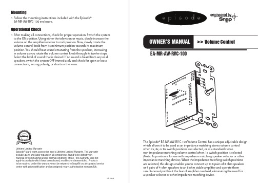
VER 100422EA-MR-AW-RVC-100 Lifetime Limited Warranty Episode ® Multi-room accessories have a Lifetime Limited Warranty. This warranty includes parts and labor repairs on all components found to be defective in material or workmanship under normal conditions of use. This warranty shall not apply to products which have been abused, modified or disassembled. Products to be repaired under this warranty must be returned to SnapAV or a designated servicecenter with prior notification and an assigned return authorization number (RA).The Episode ® EA-MR-AW-RV C-100 Volume Control has a unique adjustable design which allows it to be used as an impedance matching stereo volume control when 2x, 4x, or 8x switch positions are selected, or as a standard stereo non-impedance matching volume control when 1x switch position is selected (Note: 1x position is for use with impedance matching speaker selector or other impedance matching device). When the impedance matching switch positions are selected, this design enables you to connect up to 8 pairs of 8 ohm speakers or 4 pairs of 4-ohm speakers to an 8 ohm stable amplifier and operate them simultaneously without the fear of amplifier overload, eliminating the need for a speaker selector or other impedance matching device.Mounting1. Follow the mounting instructions included with the Episode ® EA-MR-AW-RVC-100 enclosure.Operational Check1. After making all connections, check for proper operation. Switch the system to the ON position. Using either the television or music, slowly increase the volume on the amplifier/receiver to mid-position. Now, slowly rotate the volume control knob from its minimum position towards its maximum position. You should hear sound emanating from the speakers, increasing in volume as you rotate the volume control knob through its twelve steps. Select the level of sound that is desired. If no sound is heard from any or all speakers, switch the system OFF immediately and check for open or looseconnections, wrong polarity, or shorts in the wires.Wiring and Installation1. Determine the minimum operating impedance of the amplifier to be used in the installation. This information should be in the amplifier owner’s manual. Using the speaker chart below, choose the proper position for the impedance matching switch (see Fig. 1) and put the switch in the correct position.2. The EA-MR-AW-RVC-100 has detachable connector blocks to which the amplifier and speaker wires should be connected. When connecting the speaker leads from the amplifier outputs to the volume control’s green input connector block, strip approximately 1/8 inch of insulation from the wire and twist or solder it so that there are no loose strands. Insert the wiresfrom the amplifiers outputs into the volume control connector block inputs.8 ohm Speaker ChartRecommended Switch Position 8 ohm Stable AmplifierConnecting 1 Pair of 8 ohm Speakers 1X PositionConnecting 2 Pairs of 8 ohm Speakers 2X PositionConnecting 3-4 Pairs of 8 ohm Speakers 4X PositionConnecting 5-8 Pairs of 8 ohm Speakers 8X PositionRecommended Switch Position 4 ohm Stable AmplifierConnecting 2 Pairs of 8 ohm Speakers 1X PositionConnecting 3-4 Pairs of 8 ohm Speakers 2X PositionConnecting 5-8 Pairs of 8 ohm Speakers 4X PositionConnecting 9-16 Pairs of 8 ohm Speakers 8X Position 4 ohm Speaker ChartRecommended Switch Position 4 ohm Stable AmplifierConnecting 2 Pairs of 4 ohm Speakers 4X PositionConnecting 3-4 Pairs of 4 ohm Speakers 8X Position Recommended Switch Position 8 ohm Stable AmplifierConnecting 1 Pair of 8 ohm Speakers 1X PositionConnecting 2 Pairs of 8 ohm Speakers 2X PositionConnecting 3-4 Pairs of 8 ohm Speakers 4X PositionConnecting 5-8 Pairs of 8 ohm Speakers 8X Position Note: Wires should stay consistent: right + from the amplifier to right + on the input side of the connecting block. Most speaker wire has some form of identification such as raised ribs or color coding to help determine positive and negative connections. Connect the speakers to the black output connector block following the same format as above. When the wires are connected to the blocks, plug them back into the volume control input and output. Do not apply undue pressure while plugging it into the socket. Make sure the plug is engaged in the socket properly and is not loose.Note: Volume controls need to see a minimum 4 Ohm impedance on the output side of the transformer in order for settings to appropriately protect the amplifier.Caution: Do not reverse the input and output connections, or serious damage may occur to the amplifier.。
OMEGA LVH-100A 单站水平水位传感器说明书

K-96ߜIdeal For Tanks WithInaccessible Tops Or BottomsߜConvenient SideMounting In Small Tanks ߜVery Compact Size ߜSelectable NormallyOpen or Normally ClosedThe OMEGA ®LVH-100A singlestation horizontal level switch is cost effective for level controlapplications in small tanks where it is more convenient to install a level switch through the sidewall of the tank. When the float arm is raised to the switch housing, the switch is activated. As the float drops away from the housing, it is deactivated.The movement of the float brings the imbedded magnet into close proximity to the encapsulated reed switch, causing it to actuate.The contact function may beselected as either normally open or normally closed.When triggering inductive orcapacitive loads, use the LVH-100A with the external solid state relays on page K-91.SPECIFICATIONSAccuracy:Ϯ5 mm in water Repeatability: Ϯ2 mm in water Reed Type: dry contact, SPST Thread NPT:1⁄2"Length, Overall:4"Float Diameter:0.70"Max. Temperature:-40°F to 194°FOrdering Example:LVH-100A single station polypropylene horizontal switch, $21.SINGLE STATION SWITCHES$21Basic UnitCable:2 ft, 2 wire 22 gaugeMax. Pressure Rating:25 psi @ 68°F Min. Sp. Gravity Liquid:0.8Max. Switching Current: 50 VA @ 120 Vac (CE: 30 Vrms and 42.2 Vpeak or 60 Vdc)Signal Output: Dry switch closure,selectable NO or NC states Orientation:HorizontalShown Actual SizeCANADA www.omega.ca Laval(Quebec) 1-800-TC-OMEGA UNITED KINGDOM www. Manchester, England0800-488-488GERMANY www.omega.deDeckenpfronn, Germany************FRANCE www.omega.frGuyancourt, France088-466-342BENELUX www.omega.nl Amstelveen, NL 0800-099-33-44UNITED STATES 1-800-TC-OMEGA Stamford, CT.CZECH REPUBLIC www.omegaeng.cz Karviná, Czech Republic596-311-899TemperatureCalibrators, Connectors, General Test and MeasurementInstruments, Glass Bulb Thermometers, Handheld Instruments for Temperature Measurement, Ice Point References,Indicating Labels, Crayons, Cements and Lacquers, Infrared Temperature Measurement Instruments, Recorders Relative Humidity Measurement Instruments, RTD Probes, Elements and Assemblies, Temperature & Process Meters, Timers and Counters, Temperature and Process Controllers and Power Switching Devices, Thermistor Elements, Probes andAssemblies,Thermocouples Thermowells and Head and Well Assemblies, Transmitters, WirePressure, Strain and ForceDisplacement Transducers, Dynamic Measurement Force Sensors, Instrumentation for Pressure and Strain Measurements, Load Cells, Pressure Gauges, PressureReference Section, Pressure Switches, Pressure Transducers, Proximity Transducers, Regulators,Strain Gages, Torque Transducers, ValvespH and ConductivityConductivity Instrumentation, Dissolved OxygenInstrumentation, Environmental Instrumentation, pH Electrodes and Instruments, Water and Soil Analysis InstrumentationHeatersBand Heaters, Cartridge Heaters, Circulation Heaters, Comfort Heaters, Controllers, Meters and SwitchingDevices, Flexible Heaters, General Test and Measurement Instruments, Heater Hook-up Wire, Heating Cable Systems, Immersion Heaters, Process Air and Duct, Heaters, Radiant Heaters, Strip Heaters, Tubular HeatersFlow and LevelAir Velocity Indicators, Doppler Flowmeters, LevelMeasurement, Magnetic Flowmeters, Mass Flowmeters,Pitot Tubes, Pumps, Rotameters, Turbine and Paddle Wheel Flowmeters, Ultrasonic Flowmeters, Valves, Variable Area Flowmeters, Vortex Shedding FlowmetersData AcquisitionAuto-Dialers and Alarm Monitoring Systems, Communication Products and Converters, Data Acquisition and Analysis Software, Data LoggersPlug-in Cards, Signal Conditioners, USB, RS232, RS485 and Parallel Port Data Acquisition Systems, Wireless Transmitters and Receivers。
Panasonic AV-HLC100 全能IP直播切换器说明书

Live Production CenterAV-HLC100All-in-one IP live switcher withall the functions needed for live productionsVideo, audio and camera control through single LAN cable, achieving easy controls by single operatorThe AV-HLC100 combines a live switcher, remote camera controller and audio mixer in one unit. Live audio production for small live musical performances, lectures and presentations can now be done easily by one*1: A PoE+ hub is required for the power supply. *2: See “Supported Formats” on page 5 for details. *3: NDI I HX compatible models. See our website for the models compatible with our remote camera system ( https:///en/ ). *4: See “Supported Formats” on page 6 for details. *5: Power over Ethernet Plus, IEEE 802.3at2PTZ cameraAV-HLC100InternetHD Integrated Cameras*PCAV-HLC1003User-Friendly operations and compatibility with NDI and NDI I HX standards for smooth live productionsSelect 3Djoystick target• PTZ• PIP(PinP)• TITLESelect transition target• FTB • TITLE • PIP(PinP)• BKGDTransition execution fader lever• CUT • AUTOSelect transition patternSelect source(operation of CLIP/STILL)PGM/PSTBus crosspointREC/STREAM (Start/Stop)Capture a still image LCD menu• Select PTZ camera, source of PinP and Title • PST recall for PTZ• Operation of camera’s OSD menuAudio level adjustment and level meter2Camera lens control• IRIS • ZOOM • FOCUS• Select from Auto and Manual1*1: NDI I HX compatible models. See our website for the models compatible with our remote camera system ( https:///en/ ).4input without using external IP decoder, enabling video and audio transfer, camera control through a single LAN cable.Rear ViewNDI x 1.Support Audio Input/OutputAudio input source are available from Embedded digital Audio, Analog Audio inputs and Microphone input. Those Audio source can be mixed and output to Analog Audio outputs, headphone output and Embedded with Video outputs.<Supported Formats>1080/59.94p, 1080/59.94i, 1080/29.97PsF (over 59.94i), 1080/23.98p, 1080/50p, 1080/50i, 1080/25PsF, 720/59.94p, 720/50p, 720/29.97p, 720/25p•The 1080/59.94p and 1080/50p formats are not supported for HDMI input.Video and Audio Camera control (IP)AFTER5Wide range of transitions through PinP and pattern formatsSupports PinP in one screen. You can also choose from a vast range of over 190 transition patterns, including 3D-DVE, to add effects easily.live streaming.Clip player and still image storeStill image and video data can be inserted as source, along with a variety of file formats Windows® supports (please note that some formats are not supported). Autoplay can also be set to automatically play multiple sources that have been prepared in advance.ClockPVW Audio MixerStreaming/RecordingFile menuExit to WindowWide range of video effects available for quick live productions and RTMP connections suitable for direct live streamingCLIPSTILL6PGM GUIAudio OutputSpecificationsAs of March, 2018*6: See “Supported Formats” on page 6 for details.*7: OSD function is available for Panasonic PTZ camera of SDI and HDMI output. I t is not available for those of NDI |HX output.The terms HDMI and HDMI High-De nition Multimedia Interface, and the HDMI Logo are trademarks or registered trademarks of HDMI Licensing Administrator, Inc. in the United States and other countries. Microsoft®, Windows®, Windows® XP, Windows® 7, Windows® 8, Windows® 8.1, Windows® 10 and Internet Explorer® are either registered trademarks or trademarks of Microsoft Corporation in the United States and other countries. “YouTube” and the “YouTube logo” are registered trademarks of Google Inc. “Facebook” is a registered trademark of Facebook, Inc. Skype, associated trademarks and logos and the "S" symbol are trademarks of Skype Limited.500/201803UP-1 Printed in JapanSP-HLC100PE3* Speci cations are subject to change without notice.Argentina +54 11 4122 7200Australia +61 (0) 2 9491 7400Brazil +55 11 3889 4035Canada +1 905 624 5010China +86 10 6515 8828Hong Kong +852 2313 0888Czech Republic +421 (0) 903 447 757Denmark +45 43 20 08 57Egypt +20 2 23938151Finland, Latvia, Lithuania, Estonia +358 (9) 521 52 53France +33 (0) 1 47 91 64 00Germany, Austria, Switzerland +49 (0) 6103 313887Greece +30 210 96 92 300Hungary +36 (1) 382 60 60India +91 1860 425 1860Indonesia +65 6277 7284Iran (Vida) +98 21 2271463(Panasonic Office) +98 2188791102Italy +39 02 6788 367Jordan +962 6 5859801Kazakhstan +7 727 298 0891Korea +82 2 2106 6641Kuwait +96 522431385Lebanon +96 11665557Malaysia +60 3 7809 7888Mexico +52 55 5488 1000Mongolia +976 70115577Netherlands, Belgium +31 73 640 2729New Zealand +64 9 272 0100Norway +47 67 91 78 00Pakistan +92 21 111 567 111Palestine +972 2 2988750Panama +507 229 2955Philippines +65 6277 7284Poland +48 (22) 338 1100Portugal +351 21 425 77 04Romania, Albania, Bulgaria, Macedonia +40 (0) 729 164 387Russia & CIS +7 495 9804206Saudi Arabia +966 (1) 4790499Singapore +65 6277 7284Slovak Republic, Croatia, Serbia, Bosnia, Montenegro, Slovenia +421 (0) 903 447 757South Africa +27 11 3131622Spain +34 (93) 425 93 00Sweden +46 (8) 680 26 41Taiwan +886 2 2227 6214 Thailand +662 731 8888Turkey +90 216 578 3700U.A.E. (for All Middle East) +971 4 8862142Ukraine +380 44 4903437U.K. +44(0)1344 70 69 13U.S.A. +1 877 803 8492Vietnam +65 6277 7284[Countries and Regions]Factories of AVC Networks Company have receivedISO14001:2004-the Environmental Management System certification. (Except for 3rd party ’s peripherals.)2-15 Matsuba-cho, Kadoma, Osaka 571-8503 Japanhttps:///。
FA-100全自动净水器操作使用说明书

FA-100 型高效全自动净水器设备操作使用说明书烟台博海洁净能源技术有限公司目录第一部分FA-100型高效全自动净水器 ................................. 错误!未定义书签。
第一章概述................................................... 错误!未定义书签。
第二章FA-100全自动净水器主要特点............................. 错误!未定义书签。
第三章规格及技术参数....................................... 错误!未定义书签。
第四章高效全自动净水器操作规程............................. 错误!未定义书签。
第五章高效全自动净水器维护及注意事项....................... 错误!未定义书签。
第六章滤料装填前的准备工作................................. 错误!未定义书签。
第七章填充滤料前注意事项................................... 错误!未定义书签。
第八章滤料填充的顺序(从滤室底部开始)..................... 错误!未定义书签。
第九章高效全自动净水器维修、养护工作....................... 错误!未定义书签。
第二部分高效全自动净水器配套加药装置.............................. 错误!未定义书签。
第一章加药装置的主要组成部份............................... 错误!未定义书签。
第二章投入使用前的准备工作................................. 错误!未定义书签。
第三章药剂的配制........................................... 错误!未定义书签。
- 1、下载文档前请自行甄别文档内容的完整性,平台不提供额外的编辑、内容补充、找答案等附加服务。
- 2、"仅部分预览"的文档,不可在线预览部分如存在完整性等问题,可反馈申请退款(可完整预览的文档不适用该条件!)。
- 3、如文档侵犯您的权益,请联系客服反馈,我们会尽快为您处理(人工客服工作时间:9:00-18:30)。
CV-100 自动切换装置
操
作
维
护
手
册
本手册仅供参考
CV-100 Rev. 11/20/2009
目录
安全提示 (3)
Ⅰ. 总述 (3)
Ⅱ. 安装说明 (4)
Ⅲ. 操作说明 (6)
Ⅳ. 维护 (9)
安全提示
总述:在操作此设备之前,确保遵循所有的安全警示。
电气:电路板和电路线都可能引起电击或短路,在确认电源已经断开之前,请不要触摸电路板和电源的任何部分。
Ⅰ. 总述
1.内容:
此操作手册主要介绍CV-100系列自动切换控制器及其在自动切换系统中的应用。
参看图2(Figure 2)所示的电路板接线图。
2.规格参数
外壳尺寸:295mm×238mm×146mm
电源:230 V±10% 50/60Hz
功率:10W
操作温度:-10℃– 70℃
环境温度:-10℃– 70℃
控制设置:开/关和手动/自动
输入:2个压力开关输入通道
1个远程声报警清除输入开关
2个电子称4-20mA模拟量信号输入通道
输出:2个电动球阀控制信号
2个继电器指示压力开关情况
2个继电器指示阀位(开/关)
显示:2行20个字母LCD显示
LED:6个LED指示灯
蜂鸣器:1个90分贝报警器
3.功能介绍
通过此设备可以手动或自动控制切换系统将在线氯瓶切换到备用氯瓶。
控制器接收两个压力开关信号,并提供控制信号对电动球阀进行操作。
LED和LCD指示灯将显示系统的操作情况。
2个4-20mA输入通道可接收电子称的信号,此功能是
可选功能。
图1(Figure 1)展示了CV-100系列系统的典型布局。
显示屏将会显示日期、时间、每组氯瓶的工作时间(电动球阀的开启时间)及(可选的)氯瓶的重量。
指示灯将会指示哪位氯瓶正在工作,以及一组或两组氯瓶空瓶。
操作的具体细节,请参考第三部分。
Ⅱ. 安装说明
1.电气连接:CV-100控制器的接线图,请参照下图。
2.总述(参考图2、3、4和5)
a. A/C电源连接(230V,50/60Hz)
L1: L2: GND:(接地)
b. 远程确认报警:远程报警消声输入开关(常开)。
如果有报警情况存在,
就会提供一个关闭继电器开关信号到这个输入通道,并消除声报警清除报警情况。
此功能应该连接AI4和V+。
c. 压力开关:压力开关信号输入通道(常开操作)
COM:两个压力开关信号公共端输入
PS1:1#氯瓶压力开关常开信号输入
PS2:2#氯瓶压力开关常开信号输入
压力开关应该接线到控制器的电路板上,如图3(Figure 3)所示。
d. 控制两个电动球阀的外部电缆:两个电动球阀的电源线在出玫前已经与控
制器连接好,并提供插头式连接。
电动球阀固定好后,只需要用提供的插头
式连接器将电动球阀与控制器相连即可。
注意:一定确认哪个阀球被选作V1(阀1),哪个球阀被选作V2(阀2)。
e. 电子称的模拟量(4-20mA)输入:如图1和图2(Figure 1和Figure 2),
有两个通道。
每个通道接收一个电子称的4-20mA信号。
对1#电子称的4-20mA
信号输出+线应该接到AI1,-线应该接到AIC。
同样,2#电子称的4-20mA信
号输出+线应该连接到AI2,-线应该接到AIC。
两个AIC(公共端)是连通的,可以互换使用。
f. 继电器输出指示阀位:1#阀关闭时,1#继电器(NO1和COM)将会关闭;
2#阀关闭时,2#继电器(CO2和COM)关闭。
g. 继电器输出指示压力:1#开关关闭时,5号继电器将会关闭;2#开关关闭
时,7号继电器将会关闭。
这些继电器可被用作“常开”或“常闭”。
Ⅲ. 操作说明
1.按键操作
这些键的使用方法如下。
然而,在Ⅲ-C部分会有更详细的介绍。
自动/手动切换键。
这个键有三个功能。
a.此键用于手动从一组氯瓶切换到另一组氯瓶。
按下此键,将会从一组手动
切换到另一组。
b.在停机状态,如果氯瓶不是空的,这个键可用来进入正常操作模式。
c.在组态模式,按此键可以返回上一个参数(界面)。
组态控制键。
此键用于进入(通过密码)和修改时间选项设置。
按一次
此键将会进入密码输入界面。
用和输入“100”,然后按一次进入
组态菜单。
被选中需要调整的参数将会闪烁。
做好时间调整后,按直到没有参数闪烁。
此键有两个功能。
1)在正常操作模式下,按下此键将会关闭两个电动球阀。
用于同时关闭两组氯瓶,然后显示“off”。
2)在时间设置模式下,此键也用于增加时间参数。
此键有两个功能。
1)在组态模式下,减小选中需要编辑的参数。
2)如果不是在组态模式下,此键用于清除报警和清除空瓶灯。
当有空瓶报警时,第一次按此键关闭声报警,换好氯瓶并打开瓶角阀后,再按此键关闭空瓶指示灯,清除以前的时间记录。
2.显示和LED描述。
LED灯:CV-100系列控制器在面板上包括以下LED灯。
WORK1:1#工作指示灯(绿色)。
WORK2:2#工作指示灯(绿色)。
EMPTY1:1#安瓶指示灯(红色)。
EMPTY2:2#安瓶指示灯(红色)。
RED:存在低压力情况。
GREEN:指示正常操作状态。
DISPLAY:CV-100控制器显示按以下布局。
在图4(Figure 4)中,可变量如下:
V#:阀1或阀2处于工作状态。
HR:此阀处于工作状态的小时数。
MN:此阀处于工作状态的分钟数。
WGT:重量显示(电子称输入的信号)。
DOW:星期几(Mon周一,Tue周二,Wed周三,Thu周四,Fri周五,Sat 周六,Sun周日)
MMM:月份
DD:日
YY:年
HH:当前时间的小时(24小时时间制)
MM:当前时间的分钟
在图5(Figure 5)中情况如下:
阀1处于工作状态,并持续工作2小时35分钟。
这天是周一,时间是15:45,日期是2009年10月5日。
通过阀1的重量是1755kg。
工作时间:CV-100系列控制器将会记录和显示每个阀的工作时间,这个时间从最后一次收到此组的压力开关报警信号开始记录(例如从最后一次空瓶报警开始)。
因此,如果阀1连续工作了10个小时,然后系统手动切换到另一组用阀2投加(没有从第一组压力开关收到任何信号),然后系统又切换到阀1投加,控制器将会从10个小时开始记录。
3.基本操作
a. 开始通电
一通电,CV100系统就会自动跳到阀1打开(处于工作状态)操作模式。
WORK 1 LED灯和GREEN LED应该亮。
b. 时间/日期的调整
显示应该指示正确的日期及时间。
如果没有,这些参数可以调整。
按
键一次进入组态模式(通过密码100)。
分钟参数将会闪烁,此时可以用
和来调整分钟参数。
再次按下,就可以调整小时参数,然后是星期
几、日、月,最后是年。
每个参数都可以根据需要用和来调整。
c. 重量输入设置
在组态模式下,重量输入通道可以开启/关闭、配置和显示。
用和
选择需要调整的参数。
用和来调整被选定的参数。
d.手动切换
从工作状态的阀1切换到阀2,只需要按一次。
当控制器关闭阀1打
开阀2时,WORK1 LED关闭,WORK2 LED亮起。
e.自动切换
正常操作下,一组氯瓶应该处于工作状态直到氯瓶接近空瓶。
当氯瓶接
近空瓶时,压力会急速下降。
当压力下降到用户设定的值(通常
1-5kg/cm2)时,压力开关就会报警。
当工作组接收到压力开关的信号时,
报警器就会响,EMPX LED亮起,控制器将会关闭此组的球阀,并开启
备用的另一组球阀。
以上描述的是自动切换的情况。
自动切换后,工作
人员必须按一次关闭声报警。
空瓶必须换成满瓶并与正压管路连接
好。
换好氯瓶后,需要再按一次,清除EMPX报警。
f.停止
当系统需要两组同时关闭时就会用到此功能。
在正常操作下(例如,不
在时间调整模式下)按一次关闭两组的球阀。
两组球阀关闭,但会
有声报警。
要重新进入正常操作模式(阀1处于工作状态)需要再按一
次。
但是,如果有空瓶报警的情况存在,将不会进入正常的工作状
态。
Ⅳ. 维护
当系统正常工作时,请勿打开控制器的外壳,不要触碰电源和电路板。
如果因为外界的影响而使系统不能正常工作,你可以关闭电源重新设定系统清除故障。
这些操作不会影响已经记录的信息。
