DMC1380硬件使用手册V1.1
ACS1380使用手册
ACS1380多用途数字通路传输系统使用手册北京汇讯高科电子技术有限公司目录第一章: 主控机简介 (3)1-1、概述 (3)1-2、功能特点 (3)1-3、系统连接 (4)1-4、前面板简介 (4)1-5、后面板简介 (6)第二章:功能简介 (9)2-1、检测线路延迟功能 (9)2-2、自动设置为主控功能 (9)2-3、提示和清除设备报警音 (10)第三章:单系统使用指南 (10)3-1、开机及切换显示 (10)3-2、E1链路及系统参数 (11)3-3、查看硬件配置 (12)3-4、时隙分配设置 (13)3-5、音频编码和音频解码的参数设置 (15)3-6、电话接口通道的参数设置 (16)3-7、串口的参数设置 (18)3-8、网桥配置设置 (18)3-9、运行状态显示 (19)第四章:ACS1380D双系统使用说明 (20)4-1、开机主界面及切换显示 (20)附录一:产品的技术性能指标: (21)附录二:常见故障及排除办法 (23)第一章: 主控机简介1-1、概述本设备采用总线结构,可根据需要安装不同数量的X.21/V.35(同步数据)、RS-232/RS-422(异步数据)和10Base-T(以太网,支持TCP/IP)数据通道接口卡。
各通道所需的数据带宽可按64Kbps单位自由分配(总带宽2048Kbps),各通道数据是独立传送的。
1-2、功能特点E1双向传输接口工作模式有主控、从属和独立三种工作方式可设自动识别通道卡类型通道数据速率可设显示各通道当前状态具有遥控功能,可通过计算机控制和监视设备4U 19英寸标准单机结构1-3、系统连接1-4、前面板简介ACS1380传输器的LCD彩屏面板示意图。
1、液晶显示屏幕: 带背光LCD彩屏显示器。
2、键盘:ENT:进入键/结束键;:选择键;:翻页/修改键;ESC:A系统/B系统/放大显示切换键。
3、E1指示灯:主控链路间E1信号连接指示。
绿色,指示E1信号连接正常;黄色,指示E1信号输入不正常;ACS1380ACS1380E1 INE1E1E1 IN音频电话数据音频电话数据灰色,指示主控链路卡未识别或故障。
MOTEC α系列伺服使用手册v1.1
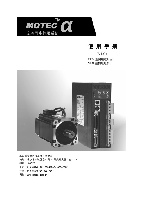
使用手册
(V1.0)
SED 型伺服驱动器 SEM 型伺服电机
北京意美德科技发展有限公司 地址: 北京市东城区东中街 58 号美惠大厦 B 座 703A 邮编: 100027 电话: 010-65542170、65546546、65542692 传真: 010-65546721 65547015 网址:
α系列伺服电机系统使用手册
章 节:
第 1 章. 伺服电机与驱动器型号 第 2 章. 安装和配线 第 3 章. 驱动器 JP2 接口(I/O 控制信号)功能说明 第 4 章. 面板操作操作说明 第 5 章. 性能调整功能说明 第 6 章. 控制模式 第 7 章. 监视项 第 8 章. 伺服驱动器工作时序图 第 9 章.驱动器 JP3/JP4(通信端口)定义、接线及通信协议 附录 1: 驱动器参数列表 附录 2:故障信息、故障原因及处理措施 附录 3:SEM 电机电气参数
1. 伺服电机与驱动器型号 ................................................................. 5 1.1 伺服电机型号定义 ................................................................. 5 1.2 伺服驱动器型号定义 ............................................................... 6 1.3 α系列驱动器与电机组合 ........................................................... 6 1.4 α系列驱动器外形及安装尺寸图 ..................................................... 8
DMC NEMS 设备管理控制台配置使用手册
设备管理控制台DMC配置使用手册1 设备管理控制台〔DMC〕22 特性的优点23 DMC硬件配置33.1主机33.28ASE/16ASE模块43.2.1模块简介43.2.2接口属性43.2.3接口指示灯43.2.4接口连接电缆54 DMC软件配置54.1配置步骤54.2Telnet重定向配置54.2.1TTY编号规那么64.2.2配置异步接口64.2.3启动Telnet重定向功能64.2.4配置监听端口74.2.5配置用户界面其他相关参数74.2.6断开Telnet重定向连接84.3DMC功能模块配置84.3.1用户管理84.3.2DMC模块相关命令84.3.3DMC配置文件94.4DMC模块的Web接口104.4.1登录DMC104.4.2浏览实验设备124.4.3反向Telnet到实验设备124.4.4管理实验设备134.4.5去除设备配置164.4.6重新检测相连设备174.4.7退出登录174.5配置举例174.5.1组网需求174.5.2组网图184.5.3配置步骤184.5.4验证194.6考前须知195 DMC在网络实训室解决方案中的应用196 FAQ191 设备管理控制台〔DMC〕在网络实训室解决方案中,设备管理控制台〔DMC,Device Management Controller〕扮演的主要角色是一个串口效劳器,用来在不同的网络用户间共享一个实验台中的网络设备的Console口,使这些用户可以通过IP网络直接实验设备的Console口,完成设备的配置,进而完成相应的实验。
每个实验台有一个DMC,用来连接本实验台里所有设备的Console口。
用户通过反向Telnet 方式实验设备的Console口。
AR28或AR46路由器在网络实训室解决方案中担当DMC的角色,其功能特性如下:1、实验设备自动识别:自动识别连接的实验设备,如交换机、路由器、防火墙等,不需要手工干预;2、可识别Quidway、H3C、3等多种逻辑;3、Web操作界面:a)浏览实验设备:用户可以直接用Web浏览器查看该控制台连接的设备类型、使用状态等信息;b)实验设备:用户在Web界面上点击实验设备,即可通过反向Telnet登录到实验设备的Console口;c)去除实验设备配置〔一键清〕:管理员用户可以选择去除一个、多个或全部实验设备的配置;d)重新检测相连实验设备:管理员用户可以要求DMC重新检测ASE卡上连接的实验设备信息;e)用户分权管理:支持用户的分权管理,为不同的用户进展不同的授权,提高系统平安性。
长沙锋电器磁碟机指南书说明书

1. Load the tableware.
tate freely.
Only clean tableware that is suitable for dish-
2. Add detergent.
washers. Remove large remnants of food from 3. Switch on the appliance .
1) 1:40 - 2:45 2) 0,850 - 1,450 3) 7,0 - 15,5
1) 3:45 2) 0,923 3) 9,5
1) 1:40 - 1:45 2) 0,750 - 0,800 3) 11,5 - 14,0
1) 1:00 2) 1,200 3) 10,0
1) 2:10 2) 1,350 3) 15,1
Cause and troubleshooting
Supply hose is kinked. ▶ Install the supply hose without kinks.
Water tap is turned off. ▶ Turn on the water tap.
Water tap is jammed or furred up. ▶ Turn on the water tap.
1) 0:15 - 0:15 2) 0,050 - 0,050 3) 4,0 - 4,0
1
3. Close the lid of the dispenser for rinse aid. a The lid clicks into position.
Adding detergent
1. Add the detergent to the dry detergent dispenser.
DMC2210硬件手册v1.2
U
U
第四章 接口引脚定义 ...................................................................... 15
U
U
4.1 接口X1 引脚定义 ..................................................................... 15
U
U
5.8 通用数字输入信号INPUT............................................................... 23
U
U
5.9 通用数字输出信号OUT................................................................. 24
U
U
3.2 板卡插座和跳线开关布局.............................................................. 12
U
U
3.3 板卡跳线设置........................................................................ 13
U
U
6.5 控制卡输出口与中间继电器的连接 ...................................................... 32
U
U
第七章 疑难解决 ........................................................................... 33
U
设备管理控制台(DMC)配置使用手册_08新版_V3.2

设备管理控制台(DMC)配置使用手册Hangzhou H3C Technologies Co., Ltd.杭州华三通信技术有限公司/solutionAll rights reserved版权所有侵权必究声明Copyright © 2008 杭州华三通信技术有限公司及其许可者版权所有,保留一切权利。
非经本公司书面许可,任何单位和个人不得擅自摘抄、复制本书内容的部分或全部,并不得以任何形式传播。
H3C、Aolynk、、IRF、H3Care、、Neocean、、TOP G、SecEngine、SecPath、COMWARE、VVG、V2G、V n G、PSPT、NetPilot、XGbus 均为杭州华三通信技术有限公司的商标。
对于本手册中出现的其它公司的商标、产品标识及商品名称,由各自权利人拥有。
修订记录目录第1章设备管理控制台概述 (8)1.1 设备管理控制台的主要功能 (8)1.2 DMC的优点 (10)1.3 DMC配置举例 (10)1.3.1 组网描述 (10)1.3.2 组网图 (11)1.3.3 配置步骤 (11)1.3.4 验证 (12)1.3.5 注意事项 (12)1.4 DMC在网络实验室解决方案中的应用 (12)第2章 DMC硬件配置 (14)2.1 主机特性 (14)2.1.1 系统规格 (14)2.1.2 主机外观 (15)2.2 8ASE/16ASE模块 (15)2.2.1 模块简介 (15)2.2.2 接口属性 (16)2.2.3 接口指示灯 (16)2.2.4 接口连接电缆 (17)第3章 DMC软件配置 (20)3.1 文件的获取和上传 (20)3.1.1 http.zip文件的获取 (20)3.1.2 http.zip文件的上传 (20)3.2 进入系统视图 (22)3.3 Telnet重定向配置 (22)3.3.1 TTY编号规则 (22)3.3.2 配置异步接口为流模式 (23)3.3.3 启动Telnet重定向功能 (24)3.3.4 配置监听端口 (24)3.3.5 配置用户界面其他相关参数 (25)3.3.6 断开Telnet重定向连接 (25)3.4 DMC功能模块配置 (26)3.4.1 用户管理 (26)3.4.2 DMC模块相关命令 (28)3.4.3 DMC配置文件 (29)3.4.4 正则表达式的使用 (31)3.5 DMC模块的Web接口 (32)3.5.1 登录DMC (32)3.5.2 浏览实验设备 (34)3.5.3 反向Telnet到实验设备 (35)3.5.4 管理实验设备 (35)3.5.5 清除设备配置 (38)3.5.6 重新检测相连设备 (39)3.5.7 退出登录 (39)3.5.8 Telnet到控制台 (39)3.5.9 关于我们 (40)第4章 FAQ (41)第5章附录 (43)插图目录图1-1 设备管理控制台在实验台中的位置 (8)图1-2 网络实验室组网示意图 (9)图1-3 DMC典型配置举例 (11)图1-4 网络实验室组网示意图 (13)图2-1 H3C AR 28-11前面板图 (15)图2-2 H3C AR 28-11后面板图 (15)图2-3 8ASE模块面板 (16)图2-4 16ASE模块面板 (17)图2-5 备份口电缆示意图 (17)图2-6 配置口电缆示意图 (18)图2-7 连接电缆线序 (18)图2-8 以太网电缆示意图 (18)图3-1 TFTP Server应用程序界面示意图 (21)图3-2 DMC用户登录页面 (33)图3-3 DMC浏览实验设备 (34)图3-4 DMC实验设备配置 (35)图3-5 DMC管理实验设备 (36)图3-6 DMC管理员登录页面 (37)图3-7 DMC管理员登录失败页面 (38)图3-8 DMC清除实验设备配置 (39)图3-9 Telnet到设备管理控制台(DMC) (40)图4-1 Web浏览器Telnet客户端配置页面 (41)表格目录表 2-1 H3C AR 28-10/28-11路由器系统说明表 (14)表 2-2 8ASE/16ASE模块接口属性 (16)表 3-1 配置步骤列表 (20)表 3-2 用TFTP下载文件 (21)表 3-3 进入系统视图 (22)表 3-4 配置异步接口为流模式 (23)表 3-5 建立Telnet重定向连接 (24)表 3-6 配置用户界面的相关选项 (24)表 3-7 配置用户界面的相关选项 (25)表 3-8 配置断开Telnet重定向连接 (25)表 3-9 配置登录用户界面的认证方式 (26)表 3-10 DMC模块相关操作命名 (28)表 3-11 dmc device-type show命令显示信息描述表 (28)表 3-12 正则表达式的元字符描述 (31)设备管理控制台配置使用手册关键词:DMC;网络实验室摘要:本文档详细描述了H3C网络实验室的实验设备管理控制台(DMC)设备的使用方法。
台达电子PCI-DMC軸卡使用手册说明书

PCI-DMC 軸卡使用手冊台達電子工業股份有限公司機電事業群33068 桃園市桃園區興隆路18號TEL: 886-3-3626301FAX: 886-3-3716301*本使用手冊內容若有變更,恕不另行通知V1.0序言感謝您使用本產品,本使用手冊提供PCI-DMC運動控制軸卡的相關資訊。
本手冊內容包含⏹硬體規格⏹電器安全須知⏹軸卡PCB配置與接腳定義⏹接線範例⏹產品安裝與配件⏹硬體與軟體安裝⏹EzDMC說明PCI-DMC運動控制軸卡產品特色PCI-DMC運動控制軸卡提供了高機能多軸擴充功能,可在1 ms內同時操控12軸的DMCNET伺服驅動器,並支援多樣化的運動控制模組(直線補間、圓弧補間、螺旋補間、連續補間)。
完整的運動控制架構,將可滿足業界更多樣化的需求。
本產品為多軸同動控制的最佳整合平台,不僅在裝配上更容易、穩定性更佳、擴充性更具彈性、是產業再升級與產品加值的不二選擇。
如何使用本操作手冊您可視本手冊為學習使用PCI-DMC運動控制軸卡之參考資訊,手冊將告訴您如何安裝、設定、使用及維護本產品。
台達電子技術服務如果您在使用上仍有問題,歡迎洽詢經銷商或本公司客服中心。
(此頁有意留為空白)目錄PCI-DMC介紹1.1 環境的建構 ····································································································· 1-21.2 硬體規格 ········································································································ 1-31.3 電氣安全須知 ·································································································· 1-41.4 PCB配置 ······································································································· 1-51.5 連結器腳位介紹 ····························································································· 1-101.5.1 PCI-DMC-A02 ························································································· 1-101.5.2 PCI-DMC-B01 ························································································· 1-141.5.3 PCI-DMC-B02 ························································································· 1-191.5.4 PCI-DMC-F01 ························································································· 1-221.5.5 PCI-DMC-F02 ························································································· 1-251.6 接線範例 ······································································································ 1-291.6.1 PCI-DMC-A02/F02/B01/B02輸入點連結外部裝置接線 ····································· 1-291.6.2 PCI-DMC- A02/F02/B01/B02輸出點連結外部裝置接線 ····································· 1-301.6.3 PCI-DMC-B01/B02高速計數器接線 ····························································· 1-311.6.4 3.3 V Compare Output接線(CN9/CN10) ······················································· 1-321.7 軸卡相容性 ··································································································· 1-33安裝介紹2.1 產品包裝與配件 ······························································································· 2-22.2 硬體安裝 ········································································································ 2-22.3 驅動程序軟體安裝前置作業················································································· 2-32.4 驅動程序軟體安裝 ···························································································· 2-72.4.1 軟體安裝程序 ···························································································· 2-72.4.2 軟體安裝程序(Windows 7 64-bit) ·································································· 2-102.5 檢視軟體包安裝結果 ························································································· 2-142.5.1 檢視軟體安裝成功 ···················································································· 2-142.5.2 檢視軟體安裝失敗 ···················································································· 2-152.6 軟體安裝失敗的處置 ······················································································· 2-162.7 將軸卡安裝在其它PCI插槽 ·············································································· 2-182.8 手動安裝驅動程序 ·························································································· 2-222.9 BCB範例使用說明·························································································· 2-29EzDMC操作說明3.1 EzDMC功能簡介 ····························································································· 3-2 3.2 EzDMC通訊連結程序 ······················································································· 3-3 3.3 搜尋PCI-DMC軸卡 ·························································································· 3-3 3.4 尋找連結的擴充模組裝置···················································································· 3-4 3.5 EzDMC的狀態列顯示 ······················································································· 3-5 3.6 串列式Motion單軸操作介面 ··············································································· 3-6 3.8 Master Security 操作介面 ················································································ 3-10 3.9 軸卡重置 ······································································································ 3-13 3.10 參數儲存功能說明 ·························································································· 3-14PCI-DMC介紹在使用PCI-DMC之前,本章節簡介PCI-DMC環境建構、硬體規格、安全須知、PCB配置、PCI_DMC腳位連接與接線範例作說明。
DMC2000硬件手册
DMC2000硬件手册深圳雷赛DMC2000硬件手册.版本1.2第一章概述1.1 产品简介DMC2000系列是基于PCI总线的高性能运动控制卡,可控制多达4个步进或伺服电机。
此系列具有即插即用、最高2.4MHZ脉冲频率、S曲线减振功能、编码器反馈、Z信号精密找零、随时变速等高级功能。
位置指令可用单路脉冲(脉冲+方向)或双路脉冲(CW脉冲+CCW脉冲)方式输出,可以是差分式,也可以是单端式。
如用于伺服控制时,每轴提供了报警(ALM),定位完成(INP),误差清除(OUT3,4,5,6),伺服开启(OUT1,2,7,8)和已准备(INPUT)等五个信号,使用户的接口和编程工作大大简化。
DMC2200可控制1至2个电机作独立或插补运动,DMC2400可控制多达4个电机。
DMC2000系列比ISA总线的DMC200功能更加强大,硬件接口上有一定的相似性,软件指令方面有一定程度的兼容性。
本产品配有WIN95/98/NT/2000下的动态链接库,方便客户编写自己的应用软件,同时提供MOTION2000调试示范软件,可演示此卡功能,方便客户测试控制卡以及电机驱动系统。
1.2 产品特点32位PCI总线,即插即用两轴圆弧和直线插补功能,3轴或4轴直线插补最大输出脉冲频率2.4MPPS 加/减速时间可任意编程脉冲输出模式:脉冲/方向、正向/反向可选T/S型速度曲线可选,非对称加减速最多4轴脉冲和方向输出,控制步进和伺服电机用于增量编码器反馈的28位上/下计数器多轴连续起动/停止可编程中断源全部I/O光隔离,耐2500VRMS电压运动中可改变速度每轴提供原点、索引信号、正负限位开关专用接口手动脉冲输入接口最多支持一个系统12块卡同时工作 Microsoft Windows 应用开发软件, MOTION2000 调试软件每轴具编码器计数和反馈功能DMC2000库和实用程序及Windows 95/98/ NT /2000 DLL1.3 技术指标性能:□控制轴数: 2轴 (DMC2200), 4轴 (DMC2400)□内部参考时钟: 9.8304MHZ□最大脉冲输出频率: 2.4MHZ线性、梯形或S曲线速度驱动方式□位置脉冲设置范围: 0--268,435,455 个脉冲(28位)□斜坡下降设置范围:0--16,777,215□加/减速设置范围: 1--65535(16位)□上/下计数器计数范围:0--268,435,455(28位)或-134217728--+134217727□脉冲速率设置: 0--2.4MPPSI/O信号:□DMC2400的通用I/O口一般是4进4出,软件设置后最多可达12进8出(8个SD输入,4个INPUT输入);DMC2200的通用I/O口一般是2进6出,软件设置后最多可达6进6出(4个SD输入,2个INPUT输入,6个通用OUT输出)。
Eaton FT1380e电子紧贴机升级包说明说明书

Eaton’s electronic FT1380e crimp machine featuresan industrial grade, built-in touchscreen with a sleek, modern display and a friendly interface that makes operation not only easy, but more accurate and efficient. The FT1380e is designed with Eaton’s crimp specsand color assembly photos already loaded to maximize assembly speed while eliminating the guesswork of hose and fitting identification.The FT1380e offers advantages that increase operator safety while saving time and money:• The ability to save unlimited favorites• Color assembly photos displayed for easy validation and accuracy• Variable retract position that cuts down on assembly time and speeds up production runs• Easy setup, calibration, and offsets• Updated lighting for better visibility• Integrated help feature with manual,tutorial, and icon quick reference guideAll of this will make a remarkableimpact on your bottom line:• Reduction in operator training time• Reduced assembly time• Reduced operator error and waste• Safe and reliable hose assemblies• Delighted customers Upgrade Kits:Standard FT1380 crimpers can now be upgraded to the new FT1380e electronic platform. All standard FT1380 units are eligible for an upgrade. The following steps will help guide you through the process of upgrading your crimper:5 Steps to next level crimping1. Contact Lomar at 1-888-AT-LOMAR (1-888-285-6627)for an initial crimp machine assessment.2. Purchase an Upgrade Kit from Eaton.Part Numbers: FT1380e-115-UPFT1380e-115-UPCSAFT1380e-230-UPFT1380e-230-UPCSA3. Ship the machine to Lomar using prepaid freight.4. Lomar upgrades the machine and implements anyadditional repairs that have been approved.5. Lomar returns the upgraded machine to the shippingaddress provided via the specified carrier.Enjoy the benefits of your new FT1380e!• Safe and reliable hose assemblies• Reduced operator error and waste• Reduced assembly timesT ake your crimper t level. Five simple steps to upgrade your crimperTurn yourold crimperinto this! See Reverse side for additional details© 2021 EatonAll Rights Reserved Printed in USADocument No.: E-EQCR-BB004-E May 2021EatonHydraulics Group USA 14615 Lone Oak Road Eden Prairie, MN 55344USATel: 952-937-9800Fax: 952-294-7722/hydraulicsEvaluationWe recommend contacting Lomar prior to sending your crimper in for an upgrade and/or issuing a Purchase Order (PO) for your upgrade.• Lomar Technical Support & Service: 1-888-AT -LOMAR (1-888-285-6627) or 1-517-563-8800• A Lomar technician will review the condition of your crimper with you. It will be helpful if Lomar can speak with someone familiar with the specific machine planned for the upgrade and ideally someone who can be near the machine while on the phone.• The purpose of the call is to provide an initial assessment as to whether your crimper may require additional repairs to complete the upgrade. The Lomar technician will evaluate and give their opinion based on information provided. Lomar will not provide a firm quotation based on the phone evaluation. Following the call, the owner of the crimper will have abetter understanding of any additional costs that may be required above and beyond the cost of the Upgrade Kit.Purchase Order(s)• The Upgrade Kit purchased from Eaton includes all parts and labor required to upgrade a machine from a fully functioning FT1380 to an upgraded FT1380e. The price includes a new skid and box for return shipment as well as all accessories that come with a new FT1380e. Please work with your Eaton account representative on pricing foran Upgrade Kit.• A purchase order for the Upgrade Kit will need to be placed with Eaton (Lomar is not authorized to sell the Upgrade Kit directly). There are four part numbers available for purchase.Upgrade Kit Part Numbers• FT1380e-115-UP : Standard 115v FT1380 Crimp Machine• FT1380e-115-UPCSA: CSA Certified 115v FT1380 Crimp Machine • FT1380e-230-UP : Standard 230v FT1380 Crimp Machine• FT1380e-230-UPCSA : CSA Certified 230v FT1380 Crimp MachineAdditional repairs may be required to bring the crimper to fully functioning operation. If additional repairs or spare parts are required or desired, these will be quoted separately by Lomar upon receipt of the crimp machine at our facility. A PO should be placed directly with Lomar for any additional repairs or parts quoted that are outside of the items included with the Upgrade Kit.Shipment of Machine• Lomar will need the crimp machine at our facility to finalize the evaluation of its condition and perform the upgrade. Please send your crimp machine to Lomar at the following address using prepaid freight: Lomar Machine & T ool Co.T ech Support Department | Plant 2 7595 Moscow Rd. Horton, MI 49246• Please include contact information with the machine so that we can reach out to you directly once the machine is received.• Please secure the machine to a skid and package with adequate protection to avoid shipping damage.Upgrade • Lomar will perform the upgrade to your crimp machine upon receipt of PO(s). Lomar will implement any other repairsor upgrades needed at the time of the Upgrade Kit installation.Return Shipment • Lomar will return your upgraded FT1380 Crimp Machine to you via the LTL carrier, account number, and ship-to address provided on your purchase order for the Upgrade Kit. Please ensure this information is included on your PO to Eaton forthe Upgrade Kit.Learn more about the FT1380e crimper:Click here to watch the video or download the sell sheet .Order your upgrade kit now and start taking advantage of these benefits today!。
MG550(1380)说明书(12.6.24更新版)

MG550/1380 型系列采煤机
6、压力表....................................................................................................52 7、电磁阀....................................................................................................52 8、两位三通换向阀、泵-马达和转阀......................................................52 9、文丘里管组件........................................................................................53 10、冷却器..................................................................................................53 11、液压制动器..........................................................................................54 12、其它附件..............................................................................................55 ★ 调高系统故障分析........................................................................................55 1、摇臂不能调高........................................................................................55 2、摇臂调高速度下降................................................................................56 3、摇臂锁不住,有下沉现象....................................................................56 第六章 辅助装置........................................................................................................67 ★ 中间框架........................................................................................................67 ★ 液压螺母........................................................................................................67 1、操作步骤................................................................................................67 2、注意事项................................................................................................68 ★ 滑靴组件........................................................................................................68 ★ 拖缆装置........................................................................................................69 ★ 喷雾冷却系统................................................................................................69 ★ 挡煤顶护板(选配)....................................................................................71 ★ 集中注油系统(选配)................................................................................71 第七章 运输、操作与检修........................................................................................79 ★ 运输................................................................................................................79 1、一般说明................................................................................................79 2、运输单元................................................................................................80 ★ 井上检查与试运转........................................................................................80 1、检查的主要内容....................................................................................80 2、试运转....................................................................................................81 ★ 解体下井运输................................................................................................81 ★ 采煤机的操作................................................................................................81 ★ 采煤机的注油................................................................................................82 ★ 采煤机的维护与检修....................................................................................84 1、维护与检修说明 ...................................................................................84 2、维护和检修内容....................................................................................86
迈信电气刀架伺服使用说明书
DMC2410软件手册v1_1
东芝C V 1 8 0系 统 调 整 步 骤
东芝C V 1 8 0系统调整步骤,使用说明书C V 1 8 0系统调整步骤使用说明书99年5月株式会社东芝© TOSHIBA Corporation ,1999.All Rights Reserved.希望l 在使用前,请详细阅读此使用说明书,完全理解其中内容后,再操作制品。
l 阅读后,请妥善保管说明书,以便随时可以使用。
l 在移置或转卖该制品时,必须将说明书与制品一起移交。
前言本使用说明书,就在进行标准型电梯(CV180) 控制装置的安装·保养·调整作业所必要的处理方法上进行了说明。
本说明书的内容的适用对象为具有控制系统基本知识的技术以及管理人员。
在实施各种作业时,必须事先熟读该说明书,根据上面记载的指示进行操作。
禁止进行说明书上记载内容以外的行为·操作。
请妥善保管好该说明书,谨请彻底管理。
使用说明书体系图控制系统操作时的注意事项系统调整程序: 6E6MA000试运转程序: 6E6M001高速运转程序: 6E6MA002乘感调整程序书: 6E6MA003故障判断: 6E6MA004调整保养指示书: 6E6MA005安全上的注意事项为了防止对管理和使用者及他人造成危害和财产的损害与未然,安全正确地使用商品。
在装置的本体以及其使用说明书上,记载有重要的内容。
请将以下内容(表示·图记号)充分理解后,再阅读本文,并遵守其记载事项。
[表示的说明]表示表示的意思! 危险表示"如果进行误操作的话,有时可能造成人员死亡或受重伤"! 注意表示“如果进行误操作的话,有时可能导致人员受伤或仅仅发生物体的损伤”[图记号的说明]图记号图记号的意思表示危险。
具体的危险内容,在图记号里及旁边的画,文章中指示出来。
表示注意。
具体的注意内容在图记号里及旁边的画,文章中指示出来。
表示禁止(不允许做的事)。
具体的禁止内容在图记号里及旁边的画,文章中指示出来。
● 表示强制(必须做的事)。
PMC-1380-3 通信管理机使用说明书_V3.0_20110907

PMC-1380通信管理机使用说明书(V3.0)目录1.前言 (1)2.系统简介 (1)2.1.硬件介绍 (1)2.2.技术参数 (1)2.3.功能特点 (2)2.4.典型系统结构及应用 (3)2.4.1.单机单网单链路结构 (3)2.4.2.单机双网单链路结构 (4)3.安装与设置 (5)3.1.PMC-1380机架式外观与尺寸 (5)3.1.1.PMC-1380机架式外观 (5)3.1.2.PMC-1380机架式背板端子效果图 (5)3.1.3.PMC-1380机架式安装尺寸 (5)3.2.硬件安装与设置 (6)3.2.1.网络连线 (6)3.2.2.网络设置 (6)3.2.3.串口设置 (7)3.2.4.串口接线 (8)4.人机界面操作说明 (9)4.1.键盘 (9)4.2.液晶显示 (9)4.2.1.默认页面 (9)4.2.2.主菜单页面 (9)4.2.3.数据查询子菜单 (10)4.2.4.参数设置子菜单 (12)4.2.5.装置维护子菜单 (14)4.2.6.装置信息子菜单 (16)5.Web维护管理平台操作说明 (17)5.1.登录管理平台 (17)5.1.1.连接通信管理机 (17)5.1.2.输入通信管理机IP地址 (17)5.1.3.输入用户名和密码 (17)5.1.4.登录管理平台 (18)5.2.通信 (18)5.2.1.网络参数 (18)5.2.2.*对时设置 (19)5.2.3.串口参数 (19)5.2.4.串口状态 (20)5.3.*设备 (21)5.3.1.设备管理 (21)5.3.2.串口复制 (22)5.3.3.串口设备 (22)5.4.*远传库 (24)5.4.1.参数配置 (24)5.4.2.远传库复制 (25)5.4.3.测点导出 (26)5.4.4.远传库数据选择 (28)5.5.系统维护 (29)5.5.1.备份恢复 (29)5.5.2.系统配置 (31)5.5.3.*系统日志 (31)5.5.4.密码修改 (32)5.5.5.*串口调试 (33)5.6.*历史数据 (34)5.6.1.定时记录 (34)5.6.2.故障录波 (35)5.6.3.数据清除 (35)5.7.保存更改 (36)5.8.重启系统 (36)6.应用示例 (36)6.1.与上位机之间的通信 (36)6.2以IEC101通信方式接入PECSTAR (36)6.3以IEC104通信方式接入PECSTAR (38)附录1:手册变更信息 (39)1.前言随着计算机及电子技术的不断进步和发展,目前越来越多的发电、配电及用电用户希望能提高自动化水平,使用高度自动化的智能化管理和控制系统。
DMC2410硬件手册v1.1
PCI总线
PCI总线 控制芯片 同时启停STA、STP 专用运动控制
芯片
外部输入+24V
非隔离
隔离
非隔离
脉冲/方向、 通用输出
PUL/DIR、 OUTPUT
通用输入 机械接口 伺服接口 编码器
INPUT
±EL、 ±SD、 ORG
INP、ALM、ERC、 SEVON、RDY
第七章 疑难解决 ......................................... 33
第八章 抗干扰措施........................................ 35
第九章 DMC2410 规格参数 ................................ 36
z 功能强大的 MOTION2410 测试软件
1.3 主要技术指标
z 每轴最大输出脉冲频率 5MHZ z 任意两轴圆弧插补功能 z 梯形/S 形对称或非对称速度曲线运动 z 运动中可改变目标位置和速度 z 四轴高速位置信息锁存输入 z 数字 IO 口最多可达 32 进 28 出 z 每轴编码器输入脉冲频率最大 4MHZ z 同一计算机系统中最多支持 8 块卡 z 支持手轮和 JOG 功能 z DMC2410 DLL 函 数 库 适 用 于 WINDOWS
雷赛公司引进美国 MOTION ENGINEERING 公司的先进技术,为 DMC2410 设计了一套易 学易用、功能丰富的运动函数库,大大缩短了用户应用软件开发、调试时间。随卡免费提供的 MOTION2410 软件,不但可以演示和测试 DMC2410 的绝大多数控制功能,而且还可方便客户 测试控制卡及电机控制系统硬件。
易维斯 泽尼斯 热升华塑料卡打印机操作手册说明书

FLEXIBILITY• W ith Zenius, you can choose to insert your cards individually or with the automatic feeder.• T he «Expert» version of Zenius features combinable encoding functions: magnetic encoding, contact and contactless chips. It takes just a few minutes to install these modules!EASE OF USE• W ith the Evolis Premium Suite ®software, you can receive notifications and easily control the printer from your computer.• E volis High Trust ® ribbons are easy to install and automatically recognized and set by the printer.SMALL FOOTPRINT• H ardly larger than a standard sheet of paper, Zenius fits perfectly into any environment, be it the office or a customer service counter.• Z enius is an eco-designed printer: very efficient sleep mode and low energy consumption.The Zenius printer is designed for single sided printing and encoding of a very large variety of plastic cards. Zenius generates color or monochrome cards, individually or in small runs, with top quality results. Zenius is a user-friendly, compact and cost-effective solution for delivering your personalized cards.ZENIUSTHE COMPACT AND AGILE CARD PRINTER©2015 Evolis. All rights reserved. Actual product(s) may differ from information stated in this document. All specifications or pictures are subject to change without prior notice. All trademarks mentioned herein belong to their respective owners. Pictures: Olivier Calvez. 07/2015. KB-ZEN1-064-ENG-A4 Rev D0. MK000494EUROPE - MIDDLE-EAST - AFRICAEvolis - 14 avenue de la Fontaine - ZI Angers-Beaucouzé 49070 Beaucouzé - FranceT +33 (0) 241 367 606 - F +33 (0) 241 367 612 - info @AMERICAS - Evolis Inc. - Fort Lauderdale - evolisinc @ ASIA-PACIFIC - Evolis Asia Pte Ltd - Singapore - evolisasia @ CHINA - Evolis China - Shanghai - evolischina @ INDIA - Evolis India - Mumbai - evolisindia @MANUAL OR AUTOMATIC CARD FEEDERGENERAL FEATURES• Direct-to-card dye-sublimation/Resin thermal transfer • Single-sided printing, edge-to-edge • 300 dpi print head (11.8 dots/mm)• 16 million colors• 16 MB memory (RAM)PRINTING PERFORMANCES• C olor (YMCKO): 120 - 150 cards/hour 1• Monochrome: 400 - 500 cards/hourINTERFACES• U SB (1.0, 1.1, 2.0, 3.0), cable supplied • E thernet TCP-IP 10BaseT, 100BaseT (Traffic Led) on the Expert versionCARD MANAGEMENT AND SPECIFICATIONS• A utomatic or manual feeding• Feeder capacity: 50 cards (0.76 mm – 30 mil)• O utput hopper capacity: 20 cards (0.76 mm – 30 mil)• C ard thickness: 0.25 to 0.76 mm (10 to 30 mil), gauge adjustment • C ard types: PVC cards, composite PVC cards, PET cards, ABS cards 1, special varnished cards 1• C ard format: ISO CR80 - ISO 7810 (53.98 mm x 85.60 mm)OPTIONAL FEATURES• C olors available: fire red & grey brown• E xpert version: Ethernet TCP-IP, encoding modules as optionsADDITIONAL ENCODING MODULES•A vailable modules:- Magnetic stripe encoder ISO 7811 HiCo/LoCo, JIS2 - Smart contact station ISO 7816-2- Contact smart card encoder - PC/SC, EMV 2000-1- C ontactless smart card encoder - ISO 14443A, B, ISO15693, MIFARE, DESFire, HID iCLASS - Other specific encoders upon request • I nternal USB or IP ports • O ptions can be combined • F actory-installed or installed on siteSAFETY• S upport for Kensington ® security lock • D ata encryption for magnetic encodingDISPLAY•P rinter LEDs• G raphical notifications from the printer 2: cleaning alerts, empty/low level ribbon and card alerts, etc.EVOLIS HIGH TRUST ® RIBBONSTo maximize the quality and durability of printed cards, the lifespan of the print head and the overall printer reliability, use Evolis High Trust ® ribbons.• A utomatic identification and setting • D elivered in a drop-in cassette for easy handling • R ibbon saver for monochrome printing List of ribbons available on SOFTWARE• D elivered with Evolis Premium Suite ® for Windows ®:- Printer driver - E volis Print Center for administration and settings - Evolis Printer Manager for graphical notification 3 - 24/7 online support - C ompatible with Windows ® (32/64 bits): XP SP3, Vista, W7, W8, W10• D elivered with cardPresso XXS Lite for designing and editing badges:- Internal database up to 50 records- Windows ® (from XP onwards) and Mac OS X • D elivered with a driver for Mac OS X (from 10.5 onwards)• L inux OS upon request • E volis Premium SDK for remote supervision of the printer, while facilitating and speeding up integration into IT systemsECO-FRIENDLY DESIGN, CERTIFICATIONS AND STATEMENT OF COMPLIANCE• S tandby, sleep modes & reduced energy consumption • C E, FCC, IEC, VCCI, CCC, KC, BIS, EAC •R oHSSIZE AND WEIGHT• S ize (H x W x D): 195 x 205 x 315 mm (7.68’’ x 8.07’’ x 12.4’’)• W eight: 3.3 kg (7.3 lbs)WARRANTY• 2-year warranty (printer and print head)4• W arranty extension available as an optionMAIN FEATURES / Full technical specifications on Easy handling, automatic ribbonrecognition and setupW eight: 3.3 kg (3.64 lbs)315 mm (12.4’’)195 mm (7.68’’’)205 mm (8.07’’)1 Under specific conditions /2 Depends on the Windows version /3 Requires the .net 4.0 client profile version4 Warranty subject to observance of specific conditions and use of Evolis High Trust ribbonsALC Technologies Pte LtdBlk 998 Toa Payoh North #07-07/08/09318993 Singapore SingaporeTel : 63541650Fax : 63544595E-mail:*******************Web : 。
艾特钢铁紧固机FT1380与FT1390的用户指南说明书
2EATON FT1380/FT1390 Crimp Machines E-EQCR-TT004-E March 2015FT1380 & FT1390Crimp MachinesFT1380The FT1380 is a benchtop crimp machine that crimps hydraulic hose assemblies up to 1 1/4" (-20) braided and four spiralwire hose. With the launch of Eaton 6S spiral hose fitting the FT1380 is now capable of crimping hydraulic hose assemblies up to 1" (-16). In addition, the FT1380 is capable of swaging thermoplastic hose and hose fittings with the optional swaging adapter kit FF16423. Additional information on the FF16423 FT1380 swaging adapter kit can be obtained from E-MEAD-TT002-E.The FT1390 crimp machine is a stand-alone machine without a base, and will crimp up to 2" (-32) braided, 2” (-32) four spiral, and 2” (-32) six spiral hydraulic hose assemblies. Both machines have programmable electronic keypads with 10 presets. These keypads simplify the hose crimping operation by allowing the machine operator to enter a predetermined setting for a specific hose type and size. The ten most often used crimp settings can be stored for one-touch retrieval. The machine will automatically crimp to the exact crimp diameter required for that hose type and size. The electronic crimp machine settings eliminate the need for spacers or shims in the crimping operation.Features • Electronic programmable keypad • 10 Crimp diameter presets • Individual die cages for each hose size • FF16423 FT1380 swaging adapter kit Benefits • Easy and quick to electronically enter crimp setting • Can pre-program 10 most popular crimp settings • Die cages easily slip in and out of machine • Machine now capable of swaging thermoplastic hoseand hose fittings FT1390Features • Electronic programmable keypad • 10 Crimp diameter presets • 2-Piece master die cage • Durable, lightweight and low cost die inserts for each size Benefits • Easy and quick to electronically enter crimp setting • Can pre-program 10 most popular crimp settings • Die cages easily slip in and out of machine.Machine Type FT1380FT1390Hose Fitting Series Sizes SizesTTC series-04 thru -20 -04 thru -32TTC12-06 thru -20 -06 thru -324S-06 thru -20 -06 thru -206S-16 only -16 thru -321EN/A -12 thru -321ZN/A-16 thru -32Specifications Dimensions 12.75" Wide X 25.75" Deep X 28.5" High29" Wide X 28" Deep X 45" High Weight 238 pounds825 pounds Electrical requirements115 volt standard. 230 volt available 115 volt standard, 230 volt available3EATON FT1380/FT1390 Crimp Machines E-EQCR-TT004-E March 2015FT1380 FT1380 Tooling and Crimp Machine Packages (Qty per package)Package Part NumberFT1380-115-5 FT1380-115-8 TTC Fitting TTC & TTC12 Part Number Description Fittings Tooling & Crimper Tooling & Crimper FT1380-115 Crimp Machine (115V)1 1FT1380-200-M1501 1FT1380-200-M1801FT1380-200-M2101 1FT1380-200-M2401 1FT1381-200-M2801FT1380-200-M3201 1FT1381-200-M3701 1FT1380-200-M420FT1381-200-M4651FT1380-1-2 For Brazil market (230V, 50/60Hz, 1.5hp)FT1380-230 Crimp Machine (230V, 50/60Hz) (optional)Mounting hardware is included.Global TTC Series 4S/6S Die Cage Applications Die Cage Crimp Range Part Number mm inFT1382-200-M320 32,0 to 37,0 1.26 to 1.46FT1382-200-M370 37,0 to 42,0 1.46 to 1.66FT1382-200-M42042,0 to 46,5 1.66 to 1.83FT1382-200-M465 46,5 to 52,0 1.83 to 2.05FT1380 Tooling and Crimp MachinePart Numbers and Packages Crimp Cages for FT1380M-Series Crimp Die Cage Applications Die Cage Crimp Range Part Number mm in FT1380–275–M0707,0 to 9,0 0.28 to 0.35FT1380–275–M0909,0 to 12,0 0.35 to 0.47FT1380–275–M12012,0 to 15,0 0.47 to 0.59FT1380–200–M150*15,0 to 18,0 0.59 to 0.71FT1380–200–M180*18,0 to 21,0 0.71 to 0.83FT1380–200–M210*21,0 to 24,0 0.83 to 0.95FT1380–200–M240*24,0 to 28,0 0.95 to 1.10FT1380–200–M280*28,0 to 32,0 1.10 to 1.26FT1380–200–M320*32,0 to 37,0 1.26 to 1.46FT1380–275–M370*37,0 to 42,0 1.46 to 1.66FT1380–275–M42042,0 to 46,5 1.66 to 1.83FT1381–200–M465* 46,5 to 52,0 1.83 to 2.05Note: Additional dies and die cage assemblies also available. Refer to website or contact Eaton.Barrel Crimp Die Cage ApplicationsDie Cage Part Number Hose Size Hose StyleFT1380-275-R5-04 -04 SAE100R5FT1380-275-R5-05 -05FT1380-275-R5-06 -06FT1380-275-R5-08 -08FT1380-275-R5-10 -10FT1380-275-R5-12 -12FT1380-275-R5-16 -16FT1380-275-R5-20 -20Hose Styles• Smooth Bore PTFE• SAE100R1AT• SAE100R2AT• HI-PAC• SAE100R6• SAE100R8• SAE100R17• Convoluted PTFE • SAE100R1• SAE100R2A • SAE100R4• SAE100R7• SAE100R12• Thermoplastic For crimp specifications on Global Skive type fittings and Global TTC & TTC12 refer to website or contact Eaton for specialty hoses.Thermoplastic Swage Application Part Number Fitting StylesFF16423 All StylesFF91042 Eaton crimper cart for FT1380Die Cage Repair Kit Complete kit, less dies.To Repair Order FT1380–200–size FT1380–2–9FT1380–275–size FT1380–2–9FT1380–201–size FT1380–2–9AFT1390 Tooling andCrimp MachinePart Numbers and PackagesFT1390 FT1390 Tooling and Crimp Machine Packages (Qty per package)Package Part Number FT 1390-115 FT 1390-115-12 FT 1390-23050 FT 1390-23050-12 FT 1390-23060 FT 1390-23060-12Crimper & Crimper & Crimper & Part Number Description Crimper Only Tooling Only Crimper Only Tooling Only Crimper Only Tooling On ly FT1390-2-1 Crimp machine (115V 60Hz 1PH) 1 1FT1390-2-3 Crimp machine (230V 50Hz 1PH) 1 1FT 1390-2-2 Crimp machine (230V 60Hz 1PH) 1 1FT1307-200-M690 Crimp die cage assembly 1 1 1FT 1307-200-M550 Crimp die cage assembly 1 1 1FT1307-200-M520 Crimp die cage assembly 1 1 1FT1307-200-M465 Crimp die cage assembly 1 1 1FT1307-200-M420 Crimp die cage assembly 1 1 1FT1307-200-M370 Crimp die cage assembly 1 1 1FT1307-200-M320 Crimp die cage assembly 1 1 1FT1307-200-M280 Crimp die cage assembly 1 1 1FT1307-200-M240 Crimp die cage assembly 1 1 1FT1307-200-M210 Crimp die cage assembly 1 1 1FT1307-200-M180 Crimp die cage assembly 1 1 1FT 1307-200-M150 Crimp die cage assembly 1 1 1Note: ET1380-2-4 die holders. Consist of 4 plates that attach to the sides of the machineand can hold up to eight die cages. Mounting hardware is included.4EATON FT1380/FT1390 Crimp Machines E-EQCR-TT004-E March 2015FT1390 Tooling andCrimp MachinePart Numbers and PackagesCrimp Cages for FT1390FT1307-200-Size, FT1209-200-Size & FT1390-200-Size die cages can be used in the FT1390 crimp machine.Die Cage Crimp RangePart Number mm inFT1307–200–M070 7,0 to 9,0 0.28 to 0.35FT1307–200–M090 9,0 to 12,0 0.35 to 0.47FT1307–200-M120 12,0 to 15,0 0.47 to 0.59FT1307–200–M150* 15,0 to 18,0 0.59 to 0.71FT1307–200–M180* 18,0 to 21,0 0.71 to 0.83FT1307–200–M210* 21,0 to 24,0 0.83 to 0.95FT1307–200–M240* 24,0 to 28,0 0.95 to 1.10FT1307–200–M280* 28,0 to 32,0 1.10 to 1.26FT1307–200–M320* 32,0 to 37,0 1.26 to 1.46FT1307–200–M370* 37,0 to 42,0 1.46 to 1.66FT1307–200–M420* 42,0 to 46,5 1.66 to 1.83FT1307–200–M465* 46,5 to 52,0 1.83 to 2.05FT1307–200 –M520* 52,0 to 55,0 2.05 to 2.17FT1307–200–M550* 55,0 to 69,0 2.17 to 2.71FT1307–200–M690* 69,0 to 73,0 2.72 to 2.87*FT1390–115–12 kit includes these 12 die cages.Note: Additional dies and die cage assemblies also available. Refer to website or contact Eaton.FT1209-200-Size & FT1390-200-Size are for use with internal skive and Global Spiral TTC fittings (SAE100R11 & SAE100R13 hose styles).FT1390-200-Size dies cages are hinged to allow ease of use when crimping large elbows. All dies are machined from tool steel.Hose Styles• Smooth Bore PTFE • Thermoplastic • SAE100R1• SAE100R2A• SAE100R4• SAE100R7• SAE100R12• Convoluted PTFE • SAE100R1AT • SAE100R2AT • HI-PAC• SAE100R6• SAE100R8• AE100R17For crimp specifications on Global Skive type fittings and Global TTC & TTC12 refer towebsite or contact Eaton for specialty hoses.Die Cage Repair Kit Complete kit, less dies.To Repair OrderFT1307–200–size FT1307–2–9FT1390–200–size FT1390–2–9FT1209–200–size FT1209–2–95 EATON FT1380/FT1390 Crimp Machines E-EQCR-TT004-E March 20156EATON FT1380/FT1390 Crimp Machines E-EQCR-TT004-E March 2015FT1380 and FT1390 Target SettingsGlobal TTC fittings, Global TTC12 fittings, & Global TTC Crimp 4S/6S fittingsEnter the number “300” into the DISPLAY and start the crimping process. If the dies crimp the fitting, measure the crimp diameter and decrease the DISPLAY setting by the same amount that you wish to decrease the crimp diameter. If the dies don’t touch the fitting, lower the DISPLAY setting by 050 to “250” and try to crimp the fitting again. If that still isn’t enough, continue to reduce the DISPLAY setting by 050 increments until the dies make contact with the fitting. Then measure the crimp diameter and decrease the DISPLAY setting by the same amount that you wish to decrease the crimp diameter. *Example:If a display setting of “178”, using GH663 hose with Global TTC fittings produces a crimp diameter of 1.600 inches, subtract the crimp specification (1.590 inches) from the diameter that you need measured (1.600- 1.590=0.010). Then, subtract “010” from the DISPLAY setting (178-010=168) and change the DISPLAY to “168”. Crimp the fitting again and measure the crimp diameter. If the crimp diameter is still too large, repeat this process.Enter the number “500” intothe DISPLAY, and start thecrimping process. If the dies crimp the fitting, measure thecrimp diameter and decreasethe DISPLAY setting by thesame amount that you wish todecrease the crimp diameter. Ifthe dies don’t touch the fitting,lower the DISPLAY setting by050 to “450” and crimp thefitting again. If that still isn’tenough, continue to reducethe DISPLAY setting by 050increments until the dies makecontact with the fitting.Then,measure the crimp diameter and decrease the DISPLAY setting bythe same amount that you wish to decrease the crimp diameter.*Example:If a display setting of “343”– using GH663 with Global TTC–produces a crimp diameter of 1.600 inches, subtract the crimp specification (1.590 inches) from the diameter that you measured (1.600-1.590=0.010). Then, subtract “010” from the DISPLAY setting (343-010=333), and change the DISPLAY to “333” Crimp the fitting again, and measure the crimp diameter. If the crimp diameter is still too large, repeat this process.Note: Record the setting for future reference.Charted target settingsThe charts on the next page provide target settings for common Aeroquip hoses.To determine target settings for hoses not included in these charts refer to procedures above or PowerSource.FT1380 procedure for determining a target setting FT1390 procedure for determining a target settingFT1380 and FT1390Target SettingsGlobal TTC fittings, Global TTC12 fittings, & Global TTC Crimp 4S/6S fittingsHoseDash DieSize Cage FT1380 FT1390 Target Dia.mm (± 0.15) in (± 0.0006) -4 -M150 074 239 15.75 0.620 -6 -M180 046 286 19.94 0.785 -8 -M240 040 205 23.88 0.940 -10 -M240 155 320 26.80 1.055 -12 -M280 172 358 31.75 1.250 -12 -M320 035 200 31.75 1.250 -16 -M370 178 343 40.39 1.590 -24 -M550 - 226 55.40 2.181 -32 -M690 - 194 68.61 2.701HoseDash DieSize Cage FT1380 FT1390 Target Dia.mm (± 0.15) in (± 0.0006) -6 -M210 114 279 22.86 0.900 -8 -M280 17 203 27.94 1.100 -10 -M280 122 308 30.48 1.200 -12 -M320 140 305 35.56 1.400 -16 -M370 313 - 43.18 1.700 -16 -M420 116 281 43.18 1.700 -20 -M465 269 - 53.34 2.100 -20 -M520 - 218 53.34 2.100 -24 -M550 - 245 55.88 2.200 -32 -M690 - 216 68.58 2.700HoseDash DieSize Cage FT1380 FT1390 Target Dia.mm (± 0.15) in (± 0.0006) -12 -M320 - - 36.65 1.443 -16 -M420 - - 43.82 1.725HoseDash DieSize Cage FT1380 FT1390 Target Dia.mm (± 0.15) in (± 0.0006) -16 -M465 - - 48.62 1.914HoseDash DieSize Cage FT1380 FT1390 Target Dia.mm (± 0.15) in (± 0.0006)-6 -M210 33 198 20.70 0.815-8 -M240 75 240 24.77 0.975-10 -M280 37 223 28.32 1.115-12 -M320 30 195 31.62 1.245-16 -M370 153 318 39.75 1.565-20 -M465 114 279 48.26 1.900-24 -M550 - 200 54.74 2.155-32 -M690 - 193 68.58 2.700HoseDash DieSize Cage FT1380 FT1390 Target Dia.mm (± 0.15) in (± 0.0006)-4 M150 134 299 17.27 0.680-6 -M180 171 336 21.21 0.835-6 -M210 53 218 21.21 0.835-8 -M210 208 373 25.15 0.990-8 -M240 90 255 25.15 0.990-10 -M240 226 391 28.59 1.126-10 -M280 48 234 28.59 1.126-12 -M280 202 388 32.51 1.280-12 -M320 65 320 32.51 1.280-16 -M370 218 383 41.40 1.630-20 -M420 351 - 49.78 1.960-20 -M465 174 - 49.78 1.960-24 -M550 - 315 57.66 2.270-32 -M420 351 - 70.87 2.790Caution: These target settings for Eaton crimp machines are provided to aid in establishing actual settings. While the settings on this chart will give crimp diameters close to, or at, the specified value, the machine operator must check to verify the actual diameter. Before using these target settings, the crimp machine must be properly calibrated. Consult your Aeroquip operator’s manual for calibration procedures.GH663 with Global TTC Crimp Fitting Hose Ends GH781 with Global TTC Crimp Fitting Hose EndsGH793 with Global TTC Crimp Fitting Hose EndsGH493 with Global TTC12 Crimp Fitting Hose EndsGH493 with Global TTC Crimp 4S Fitting Hose EndsFC606 with Global TTC Crimp 6S Fitting Hose Ends7EATON FT1380/FT1390 Crimp Machines E-EQCR-TT004-E March 20152015 EatonAll Rights ReservedPrinted in USADocument No. E-EQCR-TT004-E March 2015Assembly EquipmentTechnical Support | Service | Spare Parts (1-888-285-6627)(517-563-8800)EatonHydraulics Business USA 14615 Lone Oak Road Eden Prairie, MN 55344 USATel: 952-937-9800Fax: 952-294-7722 /hydraulics EatonHydraulics Business EuropeRoute de la Longeraie 71110 MorgesSwitzerlandTel: +41 (0) 21 811 4600Fax: +41 (0) 21 811 4601EatonHydraulics Group Asia PacificEaton BuildingNo. 7 Lane 280 Linhong RoadChangning DistrictShanghai 200335ChinaTel: (+86 21) 5200 0099Fax: (+86 21) 2230 7240。
VI-13800 电压指示器使用说明书

ALWAYS READ THESE INSTRUCTIONS BEFORE PROCEEDINGThank you for buying one of our products. For safety and fullunderstanding of its benefi ts please read this manual before use.Technical support is available from 01923 441717 and support@.CONTENTS1 Safety Information 11.1 Meaning of Symbols and Markings 11.2 P recautions 21.3 Safety Advice 42 Introduction 52.1 Inspection 52.2 Description 53 Operation 63.1 Description of LED Indicators 63.2 Use of T est Prod Shrouds 63.3 Operating Duty Ratio 73.4 P roving Check 73.5 Testing for the Presence of Hazardous Live Voltage 93.6 Interference (P hantom) Voltage 94 Maintenance 104.1 P eriodic Testing 104.2 Cleaning 104.3 Repair and Service 104.4 Storage Conditions 115 Warranty 12Specifi cations Array1. SAFETY INFORMATION41.3 Safety AdviceDepending on the internal impedance of the voltage detector there will be a different capability of indicating the presence or absence of operating voltage in case of the presence of interference voltage.A voltage detector of relatively low internal impedance, compared to the reference value of 100 k :, will not indicate all interference voltages having an original voltage value above the ELV level. When in contact with the parts to be tested, the voltage detector may discharge temporarily the interference voltage to a level below the ELV , but it will be back to the original value when the voltage detector is removed.When the indication “voltage present” does not appear, it is highly recommended installing earthing equipment before work.A voltage detector of relatively high internal impedance, compared to the reference value of 100 k :, may not permit to clearly indicate the absence of operating voltage in case of the presence of interference voltage.When the indication “voltage present” appears on a part that is expected to be disconnected from the installation, it is highly recommended confi rming by another means (e.g. use of anadequate voltage detector, visual check of the disconnecting point of the electric circuit, etc.) that there is no operating voltage on the part to be tested and to conclude that the voltage indicated by the voltage detector is an interference voltage.A voltage detector declaring two values of internal impedance has passed a performance test of managing interference voltages and is (within technical limits) able to distinguish operating voltage from interference voltage and has a means to directly or indirectly indicate which type of voltage is present.52. INTRODUCTION2.1 InspectionExamine the shipping carton for any sign of damage. Inspect the unit and any accessories for damage. If there is any damage then consult your distributor immediately.2.2 DescriptionThe Martindale VI-13800 is a development of the VI-13700 which is widely specifi ed to ensure the electrical safety of users when proving dead i.e. not hazardous live. It is constructed in accordance with the latest safety standards.The voltage tester has the following features: T ests for DC and AC Voltage up to 600V Automatic AC/DC detection Bright LED indicationFull voltage indication function without batteries P rotective resistor in probe to limit current in the event of cable damageContrasting colour of inner sheath to highlight cable damage Ergonomic and robust housing Retractable shroudsMeets fully GS38 and BS EN 61243-3:2014 Measurement category CA T IV 600VP thresholdsPolarity indication:When connected to a DC voltage source either the + or – LED will illuminate dependant on polarity. The prods are marked red (positive input) and black (negative input).7For optimum safety, the shrouds should be allowed to spring forward freely whenever the prod tips are removed from a location under test.If desired, and before the unit is connected to any source of voltage, the shrouds can be locked back by pushing and twisting 90°.The prod tips will be exposed by 3 ± 0.5mm. In this position they are GS38 compliant.The probe is sealed and the fuse that was in earlier versions has been replaced by a non-user serviceable resistor to provide protection if the cable is damaged.3.3 Operating Duty RatioThe voltage indicator should be operated (ON) for a maximum period of 30 seconds. This should be followed by a recovery period (OFF) of 4 minutes.The operating duty ratio is 8 to 1, so if the voltage indicator is only ON for 2 seconds then the OFF period need only be 16 seconds.3.4 Proving CheckBefore each use the voltage indicator should be examined fordamage, cracks, cuts or scratches to the housing, cable and prods. The cable has black outer and contrasting inner insulation, to allow damage to the cable to be easily identifi ed. If there is any doubt the voltage indicator should not be used .93.5 Testing for the Presence of Hazardous Live VoltageWarningH old the voltage indicator and test prod behind the fi ngerguards in a manner that will not obscure the voltage indication LED’s. Never touch the exposed metal test prods or any part of the voltage indicator forward of the fi nger guards while applied to hazardous voltages.While taking all required safety precautions connect both test prods to the UUT (Unit or location under test).The polarity and voltage level of any voltage present will be indicated by the illumination of the voltage indicator LED’s.3.6 Interference (Phantom) VoltageIt is possible for wiring that is ‘dead’ to indicate the apparent presence of voltage at power frequency.If wiring that is live is running in close proximity to the ‘dead’ wiring being tested, there can be capacitive or inductive coupling between the two, thereby causing interference (phantom) voltages.R efer to section 1.3 for safety advice relevant to interference voltage.11Before the unit is returned, please ensure that you have checked the unit.4.4 Storage ConditionsThe instrument should be kept in warm dry conditions away from direct sources of heat or sunlight, and in such a manner as topreserve the working life of the unit. It is strongly advised that the unit is not kept in a tool box where other tools may damage it.5. WARRANTY AND LIMITATION OF LIABILITYThis Martindale product is warranted to be free from defects in material and workmanship under normal use and service. The warranty period is 2 years and begins on the date of receipt by the end user. This warranty extends only to the original buyer or end-user customer, and does not apply to fuses, disposable batteries, test leads or to any product which, in Martindale’s opinion, has been misused, altered, neglected, contaminated, or damaged by accident or abnormal conditions of operation, handling or storage.Martindale authorised resellers shall extend this warranty on new and unused products to end-user customers only but have no authority to extend a greater or different warranty on behalf of Martindale.Martindale’s warranty obligation is limited, at Martindale’s option, to refund of the purchase price, free of charge repair, or replacement of a defective product which is returned to Martindale within the warranty period.This warranty is the buyer’s sole and exclusive remedy and is in lieu of all other warranties, expressed or implied, including but not limited to any implied warranty of merchantability or fi tness for a particular purpose. Martindale shall not be liable for any special, indirect,incidental or consequential damages or losses, including loss of data, arising from any cause or theory.Since some jurisdictions do not allow limitation of the term of an implied warranty, or exclusion or limitation of incidental or consequentialdamages, the limitations and exclusions of this warranty may not apply to every buyer. If any part of any provision of this warranty is held invalid or unenforceable by a court or other decision-maker of competent jurisdiction, such holding will not affect the validity or enforceability of any other provision or other part of that provision.Nothing in this statement reduces your statutory rights.12Speci À cationVI-13800 Voltage IndicatorElectricalNominal voltage range: 50 - 600V DC/AC rms Nominal voltage threshold indications: 50, 100, 200, 400 V DC/AC rms Voltage threshold tolerance:Conforms to BS EN 61243-3:2014Internal impedance at ELV a.c.: 214k :Polarity & voltage indication: t 12V DC/AC rms AC/DC voltage detection: automatic Range detection: automatic Response time: < 0.1sFrequency range: DC, 1 - 400HzTest current: < 3.5mA at 600V DC/AC rmsDuty ratio: 30s ON (operated) / 240s OFF (recovery)EnvironmentalTemperature & Humidity (Operating & Storage): -10°C to 55°C d 85% R.H.Altitude: up to 2000mGeneralPower: From circuit under testDimensions: 205(L) x 67(W) x 27(D) mm Weight: 130g approx.Includes: InstructionsSafetyConforms to BS EN 61243-3:2014 CA T IV 600 V Class II, Double Insulation Pollution Degree 2IP rating: IP54EMCConforms to BS EN 61326-1。
- 1、下载文档前请自行甄别文档内容的完整性,平台不提供额外的编辑、内容补充、找答案等附加服务。
- 2、"仅部分预览"的文档,不可在线预览部分如存在完整性等问题,可反馈申请退款(可完整预览的文档不适用该条件!)。
- 3、如文档侵犯您的权益,请联系客服反馈,我们会尽快为您处理(人工客服工作时间:9:00-18:30)。
2
Version 1.1
DMC1380 硬件使用手册
第一章 概 述
1.1 产品简介
DMC1380 运动控制卡是采用雷赛公司自主研发的运动控制专用芯片设计的 PCI 总线脉冲式运动控制卡,可对多个步进电机、伺服电机进行点位运动控制, 位置指令可用单路脉冲(脉冲+方向)或双路脉冲(CW 脉冲+CCW 脉冲)方式 输出,可以是差分式也可以是单端信号;同时还有专用、通用 I/O 控制功能。
技术支持热线:0755-26417593
网址:
1
目
录
DMC1380 硬件使用手册 Version 1.1
第一章 概 述 ............................................................................................................1 1.1 产品简介 ......................................................................................................1 1.2 产品特点 ......................................................................................................2 1.3 技术指标 ......................................................................................................2 1.4 应用领域 ......................................................................................................3 1.5 用户控制系统开发流程 ..............................................................................3 1.6 订货型号说明 ..............................................................................................4
1.4 应用领域
z 电子自动加工、测试设备 z 半导体自动加工、测试设备 z 医疗检测设备 z 专用机械加工设备 z 其它 3 轴专用自动化设备
1.5 用户控制系统开发流程
图 1-2 控制卡开发流程图
技术支持热线:0755-26417593
网址:
3
Version 1.1
DMC1380 PCI 总线三轴运动控制卡
硬件使用手册
Version 1.1
DMC1380 硬件使用手册 Version 1.1
©Copyright 2009 Leadtech Control Technology Co.,Ltd. All Rights Reserved.
版权说明
本手册版权归深圳市雷赛科技有限公司所有,未经雷赛公司书面许可, 任何人不得翻印、翻译和抄袭本手册中的任何内容。
第五章 常见问题解决方法 ....................................................................................16 第六章 抗干扰措施 ................................................................................................18
1.6 订货型号说明
DMC1380 硬件使用手册
货品编码 811-138000-10 812-A37ENC-30 144-372822-00 143-DE4037-03
货品名称 运动控制卡 DMC1380 接线板 ACC37-74ENC V3.0 电缆线 CABLE37-DP-20(37Pin 长 2m DB 连接线 带 DB 插头) 扁平线 CABLE40-IP/DP-03(IDE4037 连接线 长 0.3m(连接线组件))
本产品配有完整的运动控制函数动态链接库,客户可在 Windows98/NT/2000/XP 下方便地编写自己的应用软件;同时提供 Motion1380 调 试示范软件,该软件既可演示此卡功能,也可测试运动控制卡、电机驱动电路、 运动平台的工作情况。
DMC1380 运动控制卡具有编程简易、稳定可靠、价格便宜等特点,可以满 足大多数自动化设备的控制要求。
第四章 步进电机驱动器接线示例 ........................................................................15 4.1 单端输出方式接法 ....................................................................................15 4.2 差分输出方式接法.....................................................................................15
技术支持热线:0755-26417593
网址:
4
Version 1.1
DMC1380 硬件使用手册
第二章 控制卡硬件功能
2.1 内部和外部电源供电方式
DMC1380 卡内部 IC 由电脑的 PCI 总线提供的 3.3V 供电,外部接口需要用 户自己准备 12~24VDC 电源供电。
I/O 信号: z 通用 I/O 口:55 路,其中 24 路输出、31 路输入全部光耦隔离。 z 命令脉冲输出:PUL 和 DIR z 机械限位/开关信号输入:+/-EL,ORG、+/-SD(光电隔离)
通用指标: z 工作温度:0℃~50℃ z 贮存温度:-20℃~80℃ z 湿度:5~85%,非结露 z 电源:
第三章 硬件安装与设置 ........................................................................................13 3.1 硬件安装步骤 ............................................................................................13 3.2 板卡设置 ....................................................................................................13
涉及 DMC1380 控制卡软件的详尽资料以及每个函数的介绍和范例,请 参阅 DMC1380 软件使用手册。
本手册中的信息资料仅供参考。由于改进设计和功能等原因,雷赛公司 保留对本资料的最终解释权!内容如有更改,恕不另行通知!
调试机器要注意安全!用户必须在机器中设计有效的安全保护装置,在软件中 加入出错处理程序。否则所造成的损失,雷赛公司没有义务或责任对此负责。
附录 .......................................................................................................................... 19
技术支持热线:0755-26417593
网址:
第二章 控制卡硬件功能 ..........................................................................................5 2.1 内部和外部电源供电方式 ..........................................................................5 2.2 脉冲输出模式 ..............................................................................................5 2.3 限位和原点 ..................................................................................................7 2.4 原点开关信号 ..............................................................................................8 2.5 限位信号±EL ...............................................................................................8 2.6 减速信号±SD...............................................................................................9 2.7 通用数字输出口信号 ................................................................................10 2.8 通用数字输入口信号 ................................................................................10 2.9 多卡运行 .................................................................................................... 11 2.10 非隔离IO口的应用 ................................................................................12
