罗托克中文说明书(A4打印版)
罗托克(ROTORK)电动执行机构

七、故障诊断
阀位错误-当前阀位错误,需要 重新设定两个限位; 通电时电池不足-需要更换电池, 此时电动操作将被禁止; 就地控制错误-检测到无效的就 地控制信号; 掉相-检测到执行器第三端子的 第三相丢失,需要进行检修。
七、故障诊断
电池电量不足-电池电量不足, 需尽快更换电池; 电池电量用尽-需要更换电池; ESD有效-检测到ESD信号存 在。
检查执行器与阀门连接法兰螺栓有无松动; 检查执行器齿轮箱是否漏油; 检查阀位指示是否正确; 检查开关过程中有无异常声音,必要时需进行维护;
六、日常检查维护
当执行器显示电池图标时,应及时更换电池。 注意:电池更换时最好在主电源接通时进行更换,避免丢 失阀门的设定记录。
七、故障诊断
ROTORK-IQ执行器具有故障自诊断功能,调用故障诊断 菜单的方法是:按设置图所示的操作程序选择到“C r”, 即程序分支点时,按设定器上的“ ”键一次,再按 “ ”键7次,屏幕显示“H1”,即为帮助菜单。然后通过 按“ ”键,逐一查看故障信息。从H1~ H8共8个帮助 信息提示,分故障类型以高亮液晶条显示。
非侵入型现场 控制,旋钮未 穿透壳体,通 过电磁感应获
取命令
三、结构
就地控制面板可以 旋转
四、显示和操作
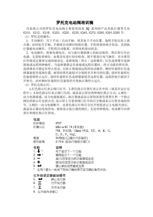
1、红色阀位指示灯-阀门打开 2、黄色阀位指示灯-中间状态 3、绿色阀位指示灯-阀门关闭 4、液晶显示屏 5、红外线传感器 6、红外信号确认灯
四、显示和操作
执控电阀行制池门器系电报报统量警警报低警
四、显示和操作
•手动操作
电动阀门手轮的作用是在电动执行器失电或 者进行检修的情况下手动控制阀门状态。手 轮的操作不受STOP的限制。
手动操作时,推动离合器手柄挂上手动挡, 摇动手轮极客开关阀,顺时钟转动为关阀, 逆时钟转动为开阀。电动操作时不必离合手 柄,手动能自动复位。
罗托克IQ3完整中文调试手册

8.
键
9. 10.
11.
键
导航 要浏览屏幕、菜单和页面,使用 和 键。 按下一个键即会产生一次移动。 按住键将会产生连续多 次移动。菜单、页面和下拉菜单相互环绕。这就意味着可通 过按下顶部的 访问屏幕底部的项目。
简写说明 该手册使用简写说明(示例) : (是指选择、 编辑、设置、保存) ,提示用户所需的按键操作。显示屏也 将在底部左侧指示相关按键。
下面的示例显示了 Setting–Limit–Close Settings, 其中功能 Action 加亮显示:
要进行更改,按下
选择。
功能和其设置选项或范围将会加亮显示:
罗托克调节阀说明书
Valtek 件号:49011 Flowserve 公司,Valtek 控制产品,电话:美国801 489 8611 1-1流体控制部 安装、使用、维修说明书Valtek MK1和MK2控制阀一般资料下面的说明用于按照Valtek ®“MK1”和“MK2”控制阀的要求进行开箱、安装和维修。
产品用户和维修人员在安装、使用和维修阀门之前,应仔细阅读本资料。
外加特性(如特殊调节、膜片执行机构、手轮和伸长阀帽)有单独的安装、使用和维修说明书。
本资料不包括Valtek 阀门定位器的资料。
有关Valtek 阀门定位器的安装、维修、故障查找、校准和使用资料,可参考相应的“安装、使用、维修说明书”。
警告:使用本设备或任何工艺控制产品时,必须遵守标准工业安全规程。
对于本设备来说,作为保修要求,尤其必须使用人身保护和起吊设备。
注:选用合适的紧固件材料是用户的责任。
通常供货商并不知道阀门的使用条件或环境。
Flowserve 公司的阀体螺栓连接的标准材料是B7/2H 。
对于不锈钢或合金材质的阀体,以及温度高于800℉/425℃的场合,可以选用B8(不锈钢)作为紧固件材料。
因此,用户除考虑一般腐蚀外,还应考虑材料的耐应力腐蚀断裂性能。
像任何机械设备一样,需要进行定期检查和维修。
如需有关紧固件材料的更详细资料,请与用户当地的Flowserve 公司代理联系。
开箱1、 阀门开箱时,应对照装箱单检查所收到的设备。
每一运输包装箱内都装有阀门和辅件的清单。
2、 从运输包装箱内起吊阀门时,应通过支架用吊带起吊,防止损坏接管和安装好的辅件。
警告:在用吊带通过支架腿起吊阀门时,必须注意被吊件的重心可能在起吊点以上。
因此,必须加以支撑,以防阀门翻倒。
否则,可能造成严重人身伤害或邻近设备的损坏。
3、如发现运输损坏,应立即与运输公司联系。
4、有任何问题时,可与用户当地的Flowserve公司代理联系。
安装1、安装阀门前,应清除管路中的污垢、焊接碎屑、锈皮或其它杂物。
罗托克AQ系列E570C ROTORK 说明书
电路板
开
关
开关
ON
OFF
1 紧急保护 可使用 不可使用 选择
2 过热保护 旁路 不旁路
旁路
3 优先 1 两个都开为关优先
4 优先 2 两个都关为开优先
这些执行器的电气安装、维护与使 用 应 符 合 1908 年 和 1944 年 版 的 《电气生产厂家特殊条例》的要求, 以 及 第 十 五 版 IEE 接 线 标 准 指 南 。 因此用户应熟悉这些条例以及其它 有关安全使用这些设备的法定条 款。用户还应根据1974年版的《安 全与健康条例》来了解他们的职 责。
解决办法:增大力矩。
iii) 可能的原因:阀门卡塞。
解决办法:检查并打开阀门。
执行器运行,但不驱动阀门 手/自动切换手柄被锁定在手动位 置。
执行器不启动 检查并更换保险丝。
7 备选功能
(参考执行器接线图)
7.1 完整的现场控制器 (见图5)
这一部分由两个旋钮组成,一个是 具有开/关两位控制的选择器;另一 个是可以锁定的、具有现场/停止/远 程三个位置的选择器。 图 5
机械安装应按手册中的介绍,并根 据有关的《英国标准实施规程》来 进行。
如果执行器的铭牌上指示出该执行 器适合安装在危险气体区域,则适 用于如下条例。
这些执行器的电气安装、维护及使 用 应 根 据 1976 年 版 BS5345 的 第 一 部 分 和 1979 年 版 BS5345 的 第 三 部 分来进行。如果不符合这些标准中 提出的要求,则不负责检查和维 修。在无故障的情况下,不应对执 行器进行任何更改或改造,因为这 将使已经获得认证的标准失效。
罗托克电动头中文说明书

IQ10至IQ35
B型非推力底座
卸下底盘的四个螺栓,确保底盘的安全,卸下底盘。
此时可看到驱动轴套和卡簧。
B3和B4型的拆卸:
(参见图7a)
用外卡簧钳涨开卡簧,同时向外拉驱动轴套。驱动轴套将从
执行器中心套筒上脱开,但卡簧仍留在轴套的槽中。
图7a
B3和B4型的重新组装
润滑驱动轴套和卡簧。将卡簧装入驱动轴套的槽中,将驱动轴套送入执行器中心套筒底部,对准键和槽。
提升1
侧面安装
非提升杆式阀门-11
顶部安装
手轮密封11
IQM调节型执行器12
IQML线性推力装置12
IQML线性行程的调整12
6接线14
地线的连接14
端子箱盖的拆卸14
电缆入口14
端子的接线15
端子箱盖的复位15
7设定16
设定程序16
设定器17
进入设定程序18
如果需要进一步有关RotorkIQ系列执行器的资料和指南,我们将根据需要提供。
如果执行器不能立即安装,则应将它保存在一个干燥的地方,直到准备接线。
如果执行器已安装好,但还没有接线,那么建议您将电缆入口的塑料塞换成缠有聚四氟乙烯的密封金属塞。
如无意外,Rotork产品的双密封结构能很好地保护内部的电气元件。
图15上紧止挡圈的定位螺栓
IQ40至IQ95
B型非推力底座
B1型
输出轴的孔和键均符合ISO 5210标准。驱动轴套无需加工。
B3和B4型
此两种驱动轴套可根据顶部带帽的螺栓来鉴别。
B3在提供时已按ISO5210标准预加工。
B4在提供时为实心,需按阀门或齿轮箱的驱动轴进行加工。
RotoRK 型号为IQ或IQM阀门说明书
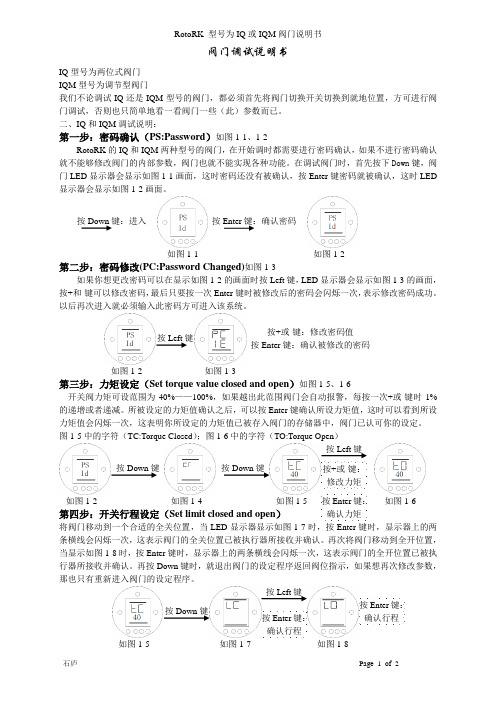
如图1-3按Left 键 按+或-键:修改密码值 按Enter 键:确认被修改的密码按Enter 键:确认密码 按Down 键:进入 按Down 键 按Down 键 按Left 键键:阀门调试说明书IQ 型号为两位式阀门IQM 型号为调节型阀门我们不论调试IQ 还是IQM 型号的阀门,都必须首先将阀门切换开关切换到就地位置,方可进行阀门调试,否则也只简单地看一看阀门一些(此)参数而已。
二、IQ 和IQM 调试说明:第一步:密码确认(PS:Password )如图1-1、1-2RotoRK 的IQ 和IQM 两种型号的阀门,在开始调时都需要进行密码确认,如果不进行密码确认就不能够修改阀门的内部参数,阀门也就不能实现各种功能。
在调试阀门时,首先按下Down 键,阀门LED 显示器会显示如图1-1画面,这时密码还没有被确认,按Enter 键密码就被确认,这时LED 显示器会显示如图1-2画面。
第二步:密码修改(PC:Password Changed)如图1-3如果你想更改密码可以在显示如图1-2的画面时按Left 键,LED 显示器会显示如图1-3的画面,按+和-键可以修改密码,最后只要按一次Enter 键时被修改后的密码会闪烁一次,表示修改密码成功。
以后再次进入就必须输入此密码方可进入该系统。
第三步:力矩设定(Set torque value closed and open )如图1-5、1-6开关阀力矩可设范围为40%——100%,如果越出此范围阀门会自动报警,每按一次+或-键时1%的递增或者递减。
所被设定的力矩值确认之后,可以按Enter 键确认所设力矩值,这时可以看到所设力矩值会闪烁一次,这表明你所设定的力矩值已被存入阀门的存储器中,阀门已认可你的设定。
图1-5中的字符(TC:Torque Closed );图1-6中的字符(TO:Torque Open )第四步:开关行程设定(Set limit closed and open )将阀门移动到一个合适的全关位置,当LED 显示器显示如图1-7时,按Enter 键时,显示器上的两条横线会闪烁一次,这表示阀门的全关位置已被执行器所接收并确认。
IQ3说明书EN

PUB002-039-00 Date of issue 12/12Table of Contents1. Introduction _____________________________31.1 Identifying Actuator Parts (3)1.2 Rotork Setting Tool (4)1.3 Introduction to this manual (5)2. Health and Safety _______________________52.1 ATEX/IECFM Certified Actuators (6)3. Storage _________________________________64. Operating your IQ Actuator ______________74.1 Operating by Hand (7)4.2 Operating Electrically (7)4.3 Display - Local Indication (8)4.4 Display – Home screen selection (9)4.5 Display Status Indication – Travel (10)4.6 Display Status Indication – Control (10)4.7 Display Alarm Indication (10)4.8 Battery Alarm (10)5. Preparing the Drive Bush _______________115.1 IQ base all sizes types A and Z3 (11)5.2 Non-Thrust Base Type B (12)6. Mounting the Actuator ________________136.1 Rising Stem Valves Top Mounted (14)6.2 Valve with Gearbox – Side Mounting (14)6.3 Non-Rising Stem Valves – Top Mounting (14)6.4 Handwheel Sealing (15)6.5 IQM Modulating Actuators (15)6.6 IQL & IQML Linear Drive Unit (15)6.7 IQL & IQML Adjusting Linear Stroke (16)7. Cable Connections _____________________167.1 Terminal Block Layout (16)7.2 Earth/Ground Connections. . . . . . . . . . . . . . . . .177.3 Removing Terminal Cover (17)7.4 Cable Entry (17)7.5 Connecting to Terminals (18)7.6 Replacing Terminal Cover (18)8. Commissioning - Basic Settings _________198.1 Connecting to the Actuator (20)8.2 Security - Password (21)8.3 Basic Settings Menu (22)8.4 Basic Settings – Limits (23)8.5 Close Settings (24)8.6 Open Settings. . . . . . . . . . . . . . . . . . . . . . . . . . .248.7 Torque Switch Bypass (25)9. Maintenance, Monitoring andTroubleshooting _______________________2610. Environmental _________________________2811. Weights and Measures _________________2912. IQ Approvals __________________________3013. Approved Fuses _______________________3214. Vibration, Shock and Noise _____________3215. Conditions of Safe Use _________________3215.1 Thread details for ATEX and IECExApproved actuators (32)15.2 Maximum constructional flamepath gaps forATEX and IECEx Approved actuators.. . . . . . . . .3316. Notes _________________________________34Battery sealing plugMetal (8 mm Allen key required)Plastic (10 mm Allen key required)1. Introduction1.1 Identifying Actuator PartsSide hand wheelRotork Bluetooth ® Setting Tool Pro4.3Display - Local Indication Fig. 4.3.1 Segment Display1. Position displayThis is the main segment display for position and torque; position indication 2. Analogue ScaleScale 0% to 100% is used whenAnalogue torque (% of rated) or3. Infra-red LEDsUsed for older models of setting tooland to initiate a data connection usingBluetooth wireless technology.4. Dual position LEDsConsisting of 2 x Yellow for midposition and 2 x bi-colour (Red / Green)for end of travel indication.5. Bluetooth indication LEDA dual intensity LED for indicating anactive connection using Bluetoothwireless technology.6. Alarm IconThis will be displayed for valve, controland actuator alarms. Alarm indicationis supported by fault description in thetext in the line above the main display.7. Battery Alarm IconThis icon will be displayed whena battery is detected as low ordischarged. "Battery low" or"Discharged" will also be displayed inthe text display above.8. Infra-Red IconThis icon flashes during setting tool9. Percentage Open IconThis icon will be displayed when aninteger open value is displayed e.g.57.3.10. Dot Matrix DisplayA high resolution 168x132 pixeldisplay for displaying setup menus anddatalogger graphs.When a positional display is active,the status and active alarms will bedisplayed.The LCD screen is made up of twolayers; the main segment display andthe dot matrix display. The displaysare dual stacked so that either displaycan be enabled to show differentinformation. This also allows acombination of both displays for addedflexibility.On power the LCD is backlit with awhite light to enable the best viewingcontrast in all lighting conditions. Foradditional positional indication, theLEDs at either side of the LCD are usedfor Closed (green), mid-travel (yellow)and Open (red) as standard. These LEDsare fully configurable in the settingsmenu or on request at time of order.4.4 Display – Home screen selectionThe actuator display can be set to showany one of the following home screens:• Position indication• Position & Digital Torque indication• Position & Analogue Torque indication• Position & Control Demand indicationThe default home screen is Position.Home screens indicate the liveconditions measured by the actuatorwhen mains power is applied. Whenmains power is switched off theactuator battery powers the displayand it will show the position indicationdisplay only.The required home screens can beset by the user either as a permanentdisplay or as a temporary display forvalve or actuator operational analysis.Temporary Home Screen display.Using the setting tool (refer to 8.1)or arrow keys, scroll throughthe available home screens untilthe required one is displayed. ThePermanent Home Screen display.Using the setting tool (refer to 8.1)connect to the actuator.From the Settings menu, selectIndication, Local Display. Fromthe available settings, select HomeScreen. Enter the password ifrequested (refer to section 8.2), selectHome screen and from the dropdownlist, select the required Home screenfor permanent display:Fig. 4.4.1 Home Screen SelectionPosition - Default valve position displayTorque (A) + Pos- Position withanalogue torque indicationOnce selected, the set display will bethe active, permanent home screen.Fig. 4.4.3 Torque (D) + PositionFig. 4.4.4 Torque (A) + PositionFig. 4.4.5 Positioner4.5 Display Status Indication –TravelThe IQ display provides real-time status indication. The top line of the text area is reserved for travel status indication. Fig 4.5.1 shows the travel status example ofCLOSED LIMITFig. 4.5.1 4.6 Display Status Indication –ControlThe bottom line of the text area isreserved for control status indicationand is displayed for approximately 2seconds after the control mode orsignal is applied.Fig 4.6.1 shows the control statusexample Remote Control.Fig. 4.6.14.7 Display Alarm IndicationThe IQ display provides alarm indicationin the form of text and alarm icons.There are 2 alarm icons:General Alarm:Battery Alarm:The general alarm icon will besupported with text in the bottom lineindicating the particular alarm, or ifmore than one is present, each alarmwill be displayed in sequence.Fig 4.7.1 shows the status example:TORQUE TRIP CLOSEDFig. 4.7.14.8Battery AlarmFig. 4.8.1The actuator checks the battery levelat approximately 1 hour intervals. Thebattery alarm icon is displayed whenthe actuator detects its battery asbeing low and the display will indicateBATTERY LOW. If the battery is flator missing the display will indicateBATTERY DISCHARGED.When a low or discharged batteryalarm is displayed the battery shouldbe replaced immediately. It is essentialthat the correct battery type is fitted tomaintain actuator certification. Refer tosection 9 for details.After replacing a battery the alarmicon will continue to be displayeduntil the next check and may takeup to 1 hour. Cycling the powerwill force a battery check and clearthe alarm.5. Preparing the Drive Bush 5.1 IQ base all sizes types A and Z3 Turn actuator onto its side, remove the cap-headed screws holding retaining plate (1) onto the thrust base and pull out the drive bush (2) complete with its bearing assembly (3). Size IQ10 to 35 have 2 screws, size IQ40 to 95—F25 bases have 8 screws, and F30 have 10 screws. Before machining the drive bush the thrust bearing must be removed.IQ10 to 18 actuators have a sealed thrust bearing located on the drive bush and retained by the split collar (4) and snap ring (5).IQ 20 to 95 have a thrust race bearing within a steel bearing housing located on the drive bush and retained by the split collar (4) and snap ring (5). The bearing is sealed within its housing by O-rings located on the drive bush andthe bearing spacer ring (6).from the drive bush prior to machining may result in damage to the bearing.Disassembly of bearing assembly allsizesLocate and remove the snap ring (5)using a suitable tool. Remove thesplit collar (4) See Fig. 5.1.1. Slide thebearing (3) off the drive bush (2).Note Additional spacer (6) and O-ringsto remove on sizes IQ20 to 95.Keep the bearings and drive bushlocating components in a safe cleanplace. The split collar (4) must be keptas a matched pair.Machine the drive bush (2) to suitthe valve stem, allowing a generousclearance on the screw thread for risingsteam threads.Fig. 5.1.11. Retaining Plate2. Drive Bush3. Sealed ThrustBearing5. Snap Ring4. Split CollarThrust BaseHousingFig. 5.1.2 F10 base assembly1. Retaining Plate2. Drive BushO-rings3. Thrust Bearing4. Split Collar6. Bearing SpacerRing5. Snap RingThrust BaseHousingFig. 5.1.3 F14 & F16 base assemblyO-rings 4. Split Collar6. Bearing SpacerRing 1. Retaining Plate2. Drive Bush3. Thrust Bearing5. Snap Ring Thrust Base HousingFig. 5.1.4 F25 & F30 base assemblyO-rings before reassembly could result in damage.Remove all swarf from the drive bush (2) ensuring all O-rings are undamaged, clean and greased (for typical greases refer to Section 11, weights and measures).Slide the bearing assembly (3) onto the drive bush (2) and ensure it is fitted down to the drive bush shoulder. On size IQ20 to IQ95 refit bearing spacer ring (6) into bearing assembly ensuring O-ring is fitted and greased. Grease and refit matched pair split collar (4) and snap ring (5).Grease and refit the drive bush bearing assembly into the thrust base housing on the actuator, ensuring that the slots in the drive bush are located into the drive dogs of the hollow output shaft.Refit the retaining plate (1) and secure with cap headed screws. For IQ40 to IQ95 tighten base retaining screws to the following torque values:F25 / FA25 Base — 8 off / M12 cap head screws: 89 Nm / 65 lbsftF30 / FA30 Base — 10off / M16 cap head screws: 218 Nm / 160 lbsft5.2 Non-Thrust Base Type BAll SizesUndo the hex head bolts securing the base plate to the gearcase and remove the base plate.The drive bush and its retaining clip can now be seen. The plate will vary withthe size of the actuator. See Fig. 5.2.1.Fig. 5.2.1Types B3 and B4 RemovalUsing external circlip pliers, expand the circlip while pulling on the drive bush. The drive bush will detach from the actuator centre column with the circlip retained in its grove. Refer to Fig. 5.2.2.Types B1 RemovalThe procedure for removal and refitting of the B1 drive bush is the same as for B3 and B4, however the circlip is replaced with a custom spring circlip. The spring operates in the same manner as the B3/B4 circlip but isexpanded using long nose-pliers. Referto Fig. 5.2.3.Fig. 5.2.36.Mounting the ActuatorRefer to Section 11 Weights and Ensure the valve is secure before fitting the actuator as the combination may be top heavy and therefore unstable.If it is necessary to lift the actuator using mechanical lifting equipment certified slings should be attached as indicated in Fig. 6.2.1 for vertical shafts and Fig. 6.2.2 for horizontal shafts.At all times trained and experienced personnel should ensure safe liftingparticularly when mounting actuators.WARNING: The actuator should shaft engagement is achieved and the actuator is secured onto the valve flange.A suitable mounting flange confirming to ISO 5210 or USA Standard MSS SP101 must be fitted to the valve.Actuator to valve fixing must confirm to Material specification ISO Class 8.8, yield strength 628 N/mm 2.via the actuator. Always lift the valve/actuator assembly via the valve.Each assembly must be assessed on anindividual basis for lifting.Fig. 6.2.16.1 Rising Stem Valves Top Mounted Fitting the Actuator and Base as a combined unit, all sizes.Fit the machined drive bush into the thrust base as previously described, lower the actuator onto the threaded valve steam, engage HAND operation and wind the hand wheel in the open direction to engage the drive bush onto the stem. Continue winding until the actuator is firmly down onto the valve flange. Wind two further turns, fit securing bolts and tighten fully to the required torque indicated in Table B.Fitting Thrust Base to Valve Actuator Fit the machined drive bush into the thrust base as previously described. Remove the thrust base from the actuator, place it on the threaded valve stem with the slotted end ofthe drive bush uppermost and turn it in the open direction to engage the thread. Continue turning until the base is positioned onto the valve flange. Fit the securing bolts but do not tighten at this stage. Lower the actuator onto the thrust base and rotate the complete actuator until the drive dogs on the actuator output shaft engage into the drive bush. Actuator flange should now be flush with the base.Continue to turn actuator until fixingholes align. Using bolts supplied fixactuator to thrust base and tightendown to required torque, see table A.Open valve by two turns and firmlytighten down onto valve flange to therequired torque, see table B.Fig. 6.1.1Fig. 6.1.2Table AFig. 6.1.3 Table B6.2 Valve with Gearbox – SideMountingCheck that the mounting flange is atright angles to the input shaft, andthat the drive bush fits the shaft andkey with adequate axial engagement.Engage HAND, offer up actuator tothe input shaft and turn handwheelto align keyway and key. Tightenmounting bolts to the required torqueindicated in Table B.6.3 Non-Rising Stem Valves – TopMountingTreat as for side mounting except thatwhen thrust is taken in the actuator,a thrust nut must be fitted above thedrive bush and securely tightened.6.4 Handwheel SealingEnsure that the sealing cap andO-ring is fitted securely to ensure that moisture does not pass down the centre column of the actuator. For valves with rising spindles a spindle or cover tube may be fitted, this will also be sealed with an O-ring and securedwith cap screws.Fig. 6.4.16.5 IQM Modulating Actuators The IQM range of actuators aresuitable for modulating control duty of up to 1,200 starts per hour.IQM have a dynamic breaking facility as standard. If mechanical overrun of the actuator and valve prove to be excessive for accurate control, the brake can be enabled. With dynamic breaking enabled, motor heating effects increase and therefore thenumber of starts may require reducing to prevent motor thermostat missioning of the IQM range is identical to the standard IQ - refer to Section 8.6.6 IQL & IQML Linear Drive Unit Consists of a lead screw assembly arrangement attached to the base of the actuator in order to provide a linear output stroke between 8 mm (3/4 in) minimum and 110 mm (4 1/4 in) maximum.The IQL/IQML actuator can be supplied with or without a yoke mounting adaptor. The adaptor consists of four pillars and a base flange to suit thevalve.Fig. 6.6.1IQML with YokeFig. 6.6.2 IQML without Yoke6.7 IQL & IQML Adjusting LinearStroke With the actuator securely fitted to the valve, but with the linear drive disconnected ensure valve is at its fully closed (down) position.Remove cover tube from actuator handwheel, locate the down stopadjustment on the linear drive unit and with two spanners loosen the lock nut, run the lock nut and tubular down stop anti-clock wise to the end of thethread.Fig. 6.7.1Turn the actuator handwheelclockwise, the linear drive will move down towards the valve spindle andcouple the linear drive to valve spindle. Turn the tubular down stop clockwise into the actuator until it comes to a mechanical stop. If the valve must close into its seat by TORQUE ACTION then back off (anticlockwise) the down stop by one third of one turn (equivalent to 1mm). Run the lock nut down onto the tubular down stop and tighten with two spanners. There is no UP STOP (open) on the linear drive unit, the mechanical stop in the valve will give this position. Refit the cover tube onto the handwheel ensuring the O-ring is fitted.The linear drive unit is pre-packed with extreme pressure multi-purpose grease MULTIS MS2, use this or an equivalent high temperature grease.A grease nipple is situated in the base of the actuator to enable lubrication of the lead screw.Periodically, depending on usage and temperature, apply two pumps of the grease gun.7. Cable Connections7.1Terminal Block LayoutFig. 7.1.1 Terminal numbers refer to connections as shown on the actuator circuit diagramremoving actuator covers.Check that the supply voltage agrees with that stamped on the actuator nameplate.A switch or circuit breaker must be included in the wiring installation or the actuator. The switch or circuit breaker must be mounted as closeto the actuator as possible and shallbe marked to indicate that it is the disconnect device for that particular actuator. The actuator must be protected with overcurrent protection devices rated in accordance with publications PUB002-018 (3-phase actuators) or PUB002-019 (single-phaseactuators).than 600 V must not be used on supply systems such as floating, or earth-phase systems, where phase to earth voltages in excess of 600 VAC could exist.7.2 Earth/Ground ConnectionsA lug with a 6 mm diameter hole iscast adjacent to the conduit entries forattachment of an external protectiveearthing strap by nut and bolt. Aninternal earth connection is alsoprovided however it must not beused alone as the protective EarthConnection.7.3 Removing Terminal CoverUsing a 6 mm Allen key loosen the fourcaptive screws evenly. Do not attemptto lever off the cover with a screwdriver this will damage the O-ring sealand may damage the flamepath on acertified unit.Fig. 7.3.1Actuators containing a RotorkBluetooth Setting Tool Pro fitted insideof the terminal compartment areidentified with a self-adhesive yellowlabel on the outside of the terminalcompartment cover.The wiring code card fixed in the coveris particular to each actuator and mustnot be interchanged with any otheractuator. If in doubt check the serialnumber on the code card with that ofthe actuator.A plastic bag in the terminalcompartment contains:• Terminal screws and washers.• Spare cover O-ring seal.• Wiring diagram.• Instruction book.Fig. 7.3.2 Actuator containing RotorkBluetooth® Setting Tool Pro.7.4 Cable EntryOnly appropriate certified explosionproof cable glands or conduit may beused in hazardous locations. The cableentries in the actuator are tapped M25x 1.5p or M40 x 1.5p.In hazardous locations, only oneappropriate certified Explosion-Proofthread adaptor per entry may be used.Fig. 7.4.1Remove plastic transit plugs. Makecable entries appropriate to the cabletype and size.Ensure that threaded adaptors, cableglands or conduit are tight and fullywaterproof. Seal unused cable entrieswith steel or brass threaded plug.In hazardous areas an appropriatecertified threaded blanking plug mustbe installed at the cable entry withoutthe use of an interposing threadadaptor.7.5 Connecting to TerminalsField wiring connections are by wiretermination ring/spade tags (refer toEx "e" enclosures below for requiredmethod) secured with the supplied4 mm (control and indication) and5 mm (power) pan head screws.that the requisite washers areused as shown in Figure 7.5.1.Failure to do so may result inconnections working loose orscrews not clamping down onwire termination tags. Springwashers must be compressed.Screw tightening torques must notexceed 1.5 Nm (1.1 lbf.ft)4 or5 mmPan HeadSpringwasherPlainwashersWire tagFig. 7.5.1power and control terminals mustbe made using AMP type 160292ring tags, for power and earthterminals and AMP type 34148 ringtabs for control terminals.Refer to the wiring diagram inside theterminal cover to identify functions ofterminals. Check the supply voltageis the same as that marked on theactuator nameplate.Remove power terminal guard.Begin by connecting power cables andreplace guard.When all connections are made ensurewiring diagram is replaced in theterminal compartment.7.6 Replacing Terminal CoverEnsure cover O-ring seal and spigotjoint are in good condition and lightly8. Commissioning - BasicSettingsAll actuator settings, Datalogger and asset management data is accessed using the supplied Rotork Bluetooth®Setting Tool Pro. Status and alarm data in addition to that shown on the home screen can also be accessed.THE CONTROL COVER MUSTNOT BE REMOVED; NO USER CONFIGURABLE SETTINGS ARE AVAILABLE WITHIN THE CONTROL ENCLOSURE. THE CONTROL COVER IS SEALED BY A QUALITY LABEL WHICH IF BROKEN MAY INVALIDATE WARRANTY.This instruction details the basic settings that must be completed before the actuator is put into service. ELECTRICAL OPERATION MUST NOT TAKE PLACE UNTIL THE BASIC SETTINGS HAVE BEEN MADE AND CHECKED.The basic settings affect the correct operation of the valve by the actuator. If the actuator has been supplied with the valve, the valvemaker or suppliermay have already made these settings.function test of the actuated valve. THIS PUBLICATION PROVIDES INSTRUCTION ON MAKING THE BASIC SETTINGS ONLY.For instruction on control and indication settings and for informationon diagnostics refer to PUB002-040.8.1 Connecting to the Actuator The Rotork Setting Tool incorporating Bluetooth wireless technology (Rotork Bluetooth ® Setting Tool Pro – BTST) is shown below. It is identified by the key symbols being clear and a clear seal between the top and bottom casings. The Infra-red only tool has filledyellow keys and a yellow seal betweencasings.The Rotork Bluetooth ® Setting Tool Pro with the relevant navigation andconfiguration keys is shown below.UpDownBackSelect/SaveRight/IncreaseLeft/DecreaseConnecting to the actuator using BluetoothThe default security set in the actuator for Bluetooth connection is by initiation using an infra red command. This means that the user must be in close proximity and in direct line of sight of the actuator.Point the setting tool at the actuator display window within a range 0.25 m (10 in) and Press key.The screen will change to the MainMenu screen.Fig. 8.1.1The Setting Tool will automatically connect using Bluetooth which takes up to 5 seconds and when connected will be indicated by blue lights illuminating on the tool and in the actuator display window. Once connected, the tool can be used without pointing it at the actuator display window.Bluetooth connection will be maintained while setting tool key commands are made. After a period of 6 minutes with no key commands, Bluetooth connection will be turned off and the Setting tool and display blue lights will go out. To manually turn off Bluetooth connection at any time, press the setting tool and keys together.8.2 Security - PasswordThe default security level for connecting to the actuator is by infra-red Bluetooth initiation. This requires that the user is at the actuator within 0.25 metre distance and in direct line of sight of the display. For instruction on connecting to the actuator referto 8.1.All actuator settings can be viewed with the actuator selected to Local, Stop or remote.To change an actuator setting, the actuator must be selected to Local or Stop and a correct password entered. If the actuator is selected to Remote and a setting is selected, the followingwarning will be displayed:Fig. 8.2.1Select OK to return to settings screen.With the actuator selected to Localor Stop and when any function isselected, the Password screen will bedisplayed:Fig. 8.2.2The factory set default passwordROTORK is displayed and the OKkey is highlighted.Press theThe setting screen will again bedisplayed. The example below showsSettings – Limits – Close Settingswith the function Actionhighlighted:Fig. 8.2.3The function and its setting option orrange will then be highlighted:Fig. 8.2.4If the user does not wish to changethe function value, press theback button to escape withoutchanging.8.3 Basic Settings MenuUse the or arrow keys to change the setting to the required value, the example below show a close action of Torquehaving been selected.Fig. 8.2.5Press the The highlight will return to the function name only and its stored setting will bedisplayed:Fig. 8.2.6The password will be requested the first time a function is selected. Once correctly entered, thepassword will not be required to be entered again for the duration of setting tool communication with the actuator. Other functions can be set as required.8.4Basic Settings – Limitsfunction test of the actuated valve. Connect to the actuator as described in Section 8.1. From the Position display home screen press the key. The main menu will be displayed. Navigate to Settings using theFig. 8.4.1The settings menu will be displayed:keysThe setting first selected to bechanged will require a password tobe entered – refer to section 8.2.The limit settings are shown below with their factory default values:1 / 122 / 123 / 124 / 125 / 126 / 127 / 128 / 129 / 1210 / 1211 / 1212 / 12Function Close Direction (1 / 12) is shown highlighted. Use to scroll throughfunctions. Functions will be highlighted in turn.8.5 Close Settings1 / 12. Close DirectionFunction sets the direction required to close the valve. Manually operate the actuator and valve to establish closing direction.to select Close Directionor2 / 12. Close ActionThe actuator can be configured closeon torque for seating valve types orlimit for non-seating valve types.absence of valvemaker instructionrefer to the following table.to select Close Actionor3 / 12. Close TorqueThe value of torque available to closethe valve can be set between 40%and 100% of rated. The actuatorrated torque value is shown on itsnameplate.to select Close Torquefunction. Use key to decrease valueand key to increase value.Instruction:Fig. 8.5.1Move the actuator and valve to theclose position. Allow for overrun bywinding the open by ½ to 1 turn.8.6 Open Settings5 / 12. Open ActionThe actuator can be configured openon torque for seating valve types orlimit for non-seating valve types.absence of valvemaker instructionset open action to “Limit”.to select Open Actionor6 / 12. Open TorqueThe value of torque available to openthe valve can be set between 40%and 100% of rated. The actuatorrated torque value is shown on itsnameplate.to select Open Torquefunction. Use key to decrease valueand key to increase value.。
罗托克电动头中文说明书

本手册提供如下介绍:*手动和电动(就地和远程)操作。
*执行器的准备和安装。
*根据有关阀门正确操作的要求,对执行器进行初级设定。
*根据现场具体控制和指示的要求,对执行器进行二级设定。
*维护-故障排除。
*销售和服务。
RotorkIQ系列执行器-全世界首家推出无需打开电气端盖即可进行调试和查询的阀门执行器。
使用所提供的红外线设定器进入执行器的设定程序,即使在危险区域,也可安全、快捷地对力矩值、限位以及其它所有控制和指示功能进行设定。
IQ的设定和调整在执行器主电源接通和断开时均可完成。
标准诊断功能可对控制系统、阀门和执行器的状态进行诊断,并通过执行器的显示屏上的图标和帮助屏幕来显示。
按一下设定器的按键即可在显示屏上对相应阀位的瞬时力矩进行监视。
内置的数据记录器可获取操作和阀门力矩数据,可提醒PC机的。
目录12保存3IQ3.1 手动操作3.2 电动操作3.33.444.1 IQ7至A和Z 4.2 IQ7至B4.3 IQ40至A和Z 4.4 IQ40至B 181919192021303061636871表如无意外,气元件。
调试IQ何电气箱盖。
箱盖而使执行Rotork每一台Rotork式:1.阀位-2.阀位-阀位指示灯供)器设定值而导断”。
(参见第●●●量等增大)将不显示。
(参见第23页3页)4.7是在执行有效(参见第4.7)都将显示,执行器大约104个螺栓固4.3 I Q40至A和Z 图8,将加,使定位螺栓与底5.1 提顶部安装a)体-执行器图19 转角箱的输入(或长形次的调节控至S450%。
保护跳断。
(详见出版物IQM(请参见第7、8)位置。
驱动器的下止手松开锁定螺(逆时(约等于1mm)。
有“上止档”线性驱动或同等的耐高脂。
线必须使用环型接,分清端子安装前应确保参见第10 P?PC Ir Cr使用距离名称1.*2.*3.4.5.,可看到窗口*5.6.7.8., 7.3按键+阀位。
用键可从(瞬间力矩+第44页第107.5新口令按键显示将变为口令。
ROTORK AWT系列说明书
'AWT' 系列出版物编号 E320C 发行日期 10/02控制与监控设备目 录基本的电相关性能 4转矩限位开关机构 5附加说明 6SyncroSET 说明 7SyncroSET 基本接线图 8SyncroSET 选项和编号 9SyncroPAK 说明 10SyncroPAK 选项 11SyncroPAK 基本配线图 12SyncroPAK 选项和编号 13SyncroPAK 远程控制电路 14在执行机构技术领域居领先地位拥有长达40余年在各种环境下的安装经验,Rotork已经发展出可靠性极强的设计理念。
今天,Rotork的执行机构在工艺领域中阀门操作和使用安全方面居于领先地位。
电动执行机构为集中控制阀门、水闸和风门挡板提供了手段。
作为工艺流程中的一部分或是在紧急情况,在有可能对环境和生命有害或有损害时,确保阀门使用的可靠性是最重要的。
执行机构是阀门、电源和控制装置3个要素的交汇点。
每个要素都有各自独特的设计要求,AWT执行机构以其完善的设计将三者结合在一起。
通过设计、研发和生产,对执行机构的测试已达到最高水平。
设计寿命、环境、振动和电气方面的测试都已实施。
每一个成品都经过一系列检测设备的测试,包括转矩、电力和机械操作以及用户控制指示平台的测试。
ROTORK 执行机构Rotork Controls Ltd, Bath, UKRotork Controls Inc, Rochester, USAAWT能够在两种基本的电形式下使用,即电机控制一体式或分体式:电机控制分体式--AWT SyncroSET电机控制分体式--AWT SyncroSET由3相发动机、减速箱以及包括可分驱动部件、限位及转矩开关和接线箱的阀门附件等部分组成。
SyncroSET执行机构必须在用户安装,连接可反向的接触器的情况下使用。
电机控制一体式--AWT SyncroPAK包括3相电机、可就地或远方控制的内置一体式启动接触器、减速箱、阀门附件--可分驱动部件、限位及转矩开关、分离式接线箱。
罗托克中文说明书

本手册提供如下介绍:
*手动和电动(就地和远程)操作。
*执行器的准备和安装。
*根据有关阀门正确操作的要求,对执行器
进行初级设定。
*根据现场具体控制和指示的要求,对执行
器进行二级设定。*维Fra bibliotek-故障排除。*销售和服务。
RotorkIQ系列执行器 - 全世界首家推出无需打开电气端盖即可进行调试和查询的阀门执行器。
如果执行器符合特殊的危险气体区域认证,则无需对其进行检查和维修。无论在任何情况下,都不应对执行器进行任何改造,因为这将使已经获得的认证失效。
在危险区域内,禁止用导电、导热体接触执行器,除非进行经特殊允许的工作,否则应切断电源,将执行器卸下并移到非危险区域进行维修或保养。
只有经过培训的、有经验的、能够胜任的人员才可被允许安装、维护和修理这些执行器,并应按照手册中的介绍来进行工作。用户和设备操作人员应根据1974年版的健康与安全条例以及与他们工作有关的规定条款来熟悉他们的职责。
提升杆式阀门-11
顶部安装
带齿轮箱的阀门-11
侧面安装
非提升杆式阀门-11
顶部安装
手轮密封11
IQM调节型执行器12
IQML线性推力装置12
IQML线性行程的调整12
6接线14
地线的连接14
端子箱盖的拆卸14
电缆入口14
端子的接线15
端子箱盖的复位15
7设定16
设定程序16
设定器17
进入设定程序18
换算表
本手册是为让用户能够胜任对RotorkIQ系列执行器的安装、操作、调试及检查而出版的。
这些执行器的电气安装、维护及使用应按照本国相关安全性的法律、法规来进行,以适应现场安装。
ROTORK IQ中文说明

Rotork IQ 系列执行器控 制 及 监 视 设 备出版物E120C 2001年11月出版前言Rotork Controls Ltd, Bath, UKRotork Controls Inc, Rochester, USA目录IQ – 控制 3执行器电气特性 4控制性能 7显示、监控及数据记录9现场总线系统11执行器接线图12紧急保护及联锁控制接线 15远程控制接线 16模拟量控制接线182IQ 执行器是对阀门进行就地及远程电动控制的非侵入式自控设备。
包括一个电机、减速齿轮、现场控制反转启动器、带电子逻辑控制的力矩、限位和监视装置。
这些装置均封装在标准为IP68(3米 - 48小时)、NEMA 4和6的双密封防水外壳内。
使用非侵入式、手持、红外线IQ 设定器可对力矩、限位和可组态的指示触点进行设定。
设定器随订单配送。
下面的说明包括标准及备选功能。
备选功能必须在订单中注明。
IQ首家无需打开电气端盖即可进行调整和查询的阀门执行机构红外线IQ设定器及基于PC的IQ-Insight软件,使IQ执行器的调整和分析更加简单、快捷。
IQ设定器用户可使用非侵入式红外线设定器,通过执行器的显示窗口浏览全部功能,每种功能都可被察看并根据需要进行调整。
即使在危险区域,也可设定力矩值、限位以及其它全部控制和指示功能。
设定可以通过用户选定密码进行保护。
设定器是独立于执行器的工具,所以组态和设定可以被控制。
只有被“允许工作”或经授权的技术人员才可进行设定。
设定过程分两级:1. 初级设定设定行程末端限位、力矩作用、力矩保护值、限位等。
2. 二级设定设定控制、指示和备选设备的功能。
所有的IQ执行器的功能在发货前均以Rotork标准设定作为默认设定,除非在订单中有特殊要求,可作相应变更。
只需简单按下设定器的一个键,执行器即可显示瞬时的阀位和力矩指示。
使用设定器,还可获取控制输入、指示输出和执行器状态的实时、分类帮助显示。
设定器的性能防水标准 IP67,防爆标准EEx ia IIC T4认证(本安型)。
天津罗托克仪表DKJ、DKZ系列电动执行器说明书

型号
给定信号
(直联式) (指令)
DKJ-2100Z DKJ-3100Z 给定信号 DKJ-4100Z (指令)
4~20mA 阻 DKJ-5100Z 抗 100Ω
额定负载 额定行程
Nm
(°)
100
在机械允许
250
的范围内,
600
数值大于
45 度均对
1600
应 4-20mA
阀位输出
额定额定 时间 S 25 40 60
二、规格、型号
智能数字式角行程电动执行器(普通型)
型号
给定信号 额定负载 额定行程 额定额定
(普通型) (指令)
Nm
(°)
时间 S
DKJ-2100
100
在机械允
给定信号
DKJ-3100
250
许的范围
(指令)
25
DKJ-4100
600 内,数值大
4~20mA 阻
DKJ-5100
1600 于 45 度均
4.定位误差:0.5~2%设定,正反作用输出,随机设定
5.阻尼特性(制动时间)
数字设定,数值范围 0~20,最小值为 0,初始值 1 为 5ms,终值 20 为 800ms,可
依据输出轴钮矩设定。
6.输入信号(指令)与输出(阀位)电隔离介质耐压 2500V
电话:022-60777808
022-60777809
10.设置角度 45°~110°范围内任意数值对应 4-20mA 11.电器限位设定范围:下限 0~50%,上限 50~100% 12.工作电源:AC220V±10% AC380V±10% 50HZ 13.使用环境:-20℃~80℃ ≤95%RH 14.执行与参照标准 JB/T8219-1999、JB/T8220-1999、JB/T10233-2001、JB/T10387-2002
罗托克电动阀培训讲义
罗托克电动阀培训稿目前我公司的罗托克电动阀主要使用的是IQ系列的产品其执行器型号有IQ10,IQ12,IQ18,IQ20,IQ25,IQ35, IQ40, IQ70, IQ90, IQ91,IQ95等。
(1)罗托克的操作:1.手动操作:压下手动/自动手柄,使其处于手动位置。
旋转手轮以挂上离合器,此时松开手柄,手柄将自动弹回初始位置,手轮将保持啮合状态,直到执行器被电动操作,手轮将自动脱离,回到电机驱动状态。
2.电动操作:检察电源电压,应与执行器铭牌上的标识相符,然后即可开启电源。
无需检查相位。
如果没有进行初步检查,则不要进行电气操作,至少要用红外线设定器来完成初级设定。
选择现场/停止/远程操作:红色选择器可选择现场或远程两种操作。
当选择器锁定在就地或远程位置时,停止功能仍然有效。
选择器也可锁定在停止状态,以防止现场或远程的电动操作。
顺时针旋转红色选择器旋钮至现场位置,相邻的黑色旋钮可分别转至开和关的位置;逆时针旋转红色旋钮则停止运行。
逆时针旋转红色选择器旋钮至远程位置,远程控制只能用于开和关,此时顺时针旋转红色旋钮仍可使执行器停止运行。
(2)罗托克指示灯:1.红色指示灯表示阀门打开,2.黄色指示灯黄灯表示在中间(就是在运行过程中),3.绿色指示灯表示阀门关闭,液晶显示屏有两种阀位指示方式:1.阀位一动力电源接通,动力电源接通后,执行器液晶显示屏的淡黄色背景灯和一个指示阀位的指示灯也将点亮,显示屏上可看到阀门打开的百分数或表示行程末端的符号。
2.阀位一动力电源断开。
由黄色指示灯和百分比开度值表示主电源关闭后,液晶显示器由电池供电,继续显示执行器的阀位。
无论何种情况,电池都不向背景灯和阀位指示灯供电。
2.执行器的设定程序执行器与阀门连接可靠后,接通主电源,并将执行器选择在就地或停止位置。
按键,执行器显示将改变,显示力矩+阀位。
按键,执行器显示将改变,显示保护口令。
执行器的设定功能可以用口令进行保护。
rotork 驱动器手册

工程能力
罗托克齿轮箱拥有在阀门技术领域从业数十年的工 程技术专家。选择罗托克就是选择专业。 我们有着 世界一流的工程团队和最先进的设计方法,使我们 能够致力于为您提供与时俱进的创新工程技术。
概念成型和证明: • 3D快速模型打印机的应用,使3D概念模型的快速生成成
为现实: 通过100micron高分辨率的熔融沉积快速成型3D 打印机可生成高牢靠性ABS树脂部件。 • 快速成型过程中的生产校验程序使得一些不确定性的因素 在设计过程中就被剔除了,这意味着产品灵活性的优化在 早期的研发过程中进行。
蜗杆传动齿轮箱
AB
系列
蜗杆传动齿轮箱
IW
系列
重载型AB系列部分回转齿轮箱,采用铸铁箱体,适用于球 阀、旋塞阀及蝶阀,广泛应用于水厂、天然气、化工工业、 电厂和工业领域。
扭矩达到32000Nm,15个规格,速比从34:1到729:1.
• 铸铁箱体 • 轴向滚针轴承 • 结构坚固,适用于任何工作环境 • IP67密封
灵活的应用工程能力:
• 我们拥有丰富的产品知识,专业的设计和具有强烈质量 意识的员工,以此来为客户提供独一无二的解决方案,因 此,我们能够达到对技术严格要求的客户所期待的服务标 准。
技术精湛和经验丰富的团队:
• 从新产品概念产生到交付客户使用,专业的研究和发展团 队自始至终都在为新产品的设计和发展保驾护航。
内容
简介
2
工程能力
3
测试设备
4
品质保证
5
网点信息 部分回转产品
6
多回转产品
8
阀门安装组件
13
阀门配件
16
罗托克集团信息
17
Rotork 是阀门自动化和流体控制全球市场的领导者。 我们的产品和服务帮助着世界各组织机构提高工作效 率,确保安全和保护环境。
上海罗托克自动化仪表 RDX 系列旋进旋涡流量计 说明书

■上海罗托克自动化仪表有限公司RDXRDX型智能旋进流量计一. 概述:当沿着轴向流动的流体进入流量传感器入口时,旋涡发生体强迫流体进行旋转运动,于是在旋涡发生体中心产生旋涡流,旋涡流在文丘利管中旋进,到达收缩段突然节流使旋涡流加速,当旋涡流进入扩散段,因回流作用强迫进行旋进式二次旋转。
此时旋涡流的旋转频率与介质流速成正比,并为线性。
两个压电传感器检测的微弱电荷信号经前置放大器差动放大、滤波、整形后变成两路频率与流速成正比的脉冲信号,同时处理电路对两路的脉冲信号进行相位比较和判别,剔除干扰信号,而对正常的流量信号进行计数处理。
图图1外观原理图二.特点:●采用独特的双传感器技术和电路处理技术,有效地解决了压力波动和机械振动对该类型流量计的干扰,计量准确可靠。
●集温度、压力、流量传感器和智能流量积算仪于一体,可对被测气体温度、压力和压缩因子自动跟踪修正,直接计量气体的标准体积流量和总量。
●补偿仪对天然气压缩因子的修正模型中,具有AGA NX-19与采用SGERG-88方程的两种方法可选。
●采用微功耗高新技术,凭内外电源均可工作,内电池可连续使用五年以上。
●无机械转动部件,高可靠,稳定性好,维修量少,对介质适应性好。
●大屏幕LCD显示标准体积流量、标准体积总量、温度、压力和电池容量,显示清晰直观,读数方便。
●功能强大,四种补偿方式、四种脉冲信号输出、三种历史数据记录方式、两种标准电流信号输出方式可选。
●可通过RS485接口组成电话通信网络和GPRS无线通信网络,安全可靠,可方便实现自动化管理。
RS485通信协议符合MODBUS协议。
●表头可180°随意旋转,安装方便。
●采用四通阀门设计,便于压力传感器的保护和在线对压力精度进行检定。
三.技术参数3.1主要参数 表 13.2 适用介质天然气、城市煤气、压缩空气、氮气、氧气(流量计须经脱脂工艺处理)、烷类及工业惰性气体等。
3.3 使用条件环境温度:-30℃~+60℃; 介质温度:-20℃~+80℃; 大气压力:70kPa ~106kPa ; 相对湿度:5%~95%。
罗托克TY_3100调试说明书
罗托克TY_3100调试说明书先将手动调至中间位置,在通电前将操作方式改为就地操作。
两部分完成后,我们选择打开电源,然后观察执行机构的方向是否与阀门的方向一致。
如果没有,我们需要将电源线更改为相位。
那我们要限位,把阀门移到坐位,然后万用表蜂鸣器齿轮,然后检查限位有的变成关闭点,只有在近点是正确的,如果不是近点关闭,调整间距直到调整到正确位置。
罗托克电动执行机构调试完位置后,需要调试全开位置的位置。
在调整开限位之前,我们还需要检查开限位的信号是否正确。
调整好后,来回移动阀门数次,观察信号是否正常。
然后我们需要调试反馈。
反馈电流是否正确很重要。
由于反馈电流直接影响给定信号,因此保证反馈电流的准确性很重要。
在调试过程中,先向万用表输入,串入反馈回路,然后关闭执行器。
此时,观察万用表的反馈值。
如果为4mA,则反馈值正确。
如果没有偏差,则需要调试。
将零位电位器的反馈值调试到正确值,然后执行器完全打开。
下一步将操作模式打开到远程操作模式,通过信号发生器输入信号4ma,看阀门改变坐位,然后输入值20ma,看是否全开,然后分别对应给定的检查反馈是否与我们给定的值相同。
如果有错误,则需要重复上述步骤,一直调试到合格为止。
罗托克电动执行机构与阀门的安装情况:1、手动转动阀门,检查无异常情况,并使阀门处于全关位置。
2、将支架固定在阀门上。
3、将联轴器的一端套在阀门芯轴上。
4、用手柄驱动至全关位置(指针正指SHUT、0刻度),将输出轴插入联轴器四方孔内。
5、紧固支架与电动执行机构和阀体间的连接螺栓。
6、用手柄驱动执行机构全程,确认运行平稳、无偏心、无歪斜,检查阀门在执行机构开度指示范围能否实现全关和全开。
注意:用力不可过猛,否则会导致执行机构超程运行而造成损坏。