污水处理英文翻译解析
污水处理的英文文献翻译(1)
Nutrient removal in an A2O-MBR reactor with sludgereductionABSTRACTIn the present study, an advanced sewage treatment process has been developed by incorporating excess sludge reduction and phosphorous recovery in an A2O-MBR process. The A2O-MBR reactor was operated at a flux of 77 LMH over a period of 270 days. The designed flux was increased stepwise over a period of two weeks. The reactor was operated at two different MLSS range. Thermo chemical digestion of sludge was carried out at a fixed pH (11)and temperature (75℃) for 25% COD solubilisation. The released pbospborous was recovered by precipitation process and the organics was sent back to anoxic tank. The sludge digestion did not have any impact on COD and TP removal efficiency of the reactor. During the 270 days of reactor operation, the MBR maintained relatively constant transmembrane pressure. The results based on the study indicated that the proposed process configuration has potential to reduce the excess sludge production as well as it didn't detonated the treated water quality.Keywords: A2O reactor; MBR; Nutrient removal; TMP1. IntroductionExcess sludge reduction and nutrients removal are the two important problems associated with wastewater treatment plant. MBR process has been known as a process with relatively high decay rate and less sludge production due to much longer sludge age in the reactor (Wenet al., 2004). Sludge production in MBR is reduced by 28-68%, depending on the sludge age used (Xia et al.,2008). However, minimizing the sludge production by increasing sludge age is limited due to the potential adverse effect of high MLSS concentrations on membrane (Yoon et al., 2004). This problem can be solved by introducing sludge disintegration technique in MBR (Young et al., 2007). Sludge disintegration techniques have been reported to enhance the biodegradability of excess sludge (Vlyssides and Karlis, 2004). In overall, the basis for sludge reduction processes is effective combination of the methods for sludge disintegration and biodegradation of treated sludge. Advances in sludge disintegration techniques offer a few promising options including ultrasound (Guo et al., 2008), pulse power (Choi et al.,2006), ozone (Weemaes et al., 2000), thermal (Kim et al., 2003), alkaline (Li et al., 2008) acid (Kim et al., 2003) and thermo chemical(Vlyssides and Karlis, 2004). Among the various disintegration techniques, thermo chemical was reported to be simple and cost effective (Weemaes and Verstraete, 1998). In thermal-chemical hydrolysis, alkali sodium hydroxide was found to be the most effective agent in inducing cell lysis (Rocker et al., 1999). Conventionally, the nutrient removal was carried out in an A2O process. It has advantage of achieving, nutrient removal along with organic compound oxidation in a single sludge configuration using linked reactors in series (Tchobanoglous et al., 2003). The phosphoroes removal happens by subjecting phosphorous accumulating organisms (PAO) bacteria under aerobic and anaerobic conditions (Akin and Ugurlu, 2004). These operating procedures enhance predominance PAO, which are able to uptake phosphorous in excess. During the sludge pretreatment processes the bound phosphorous was solubilised and it increases the phosphorousconcentration in the effluent stream (Nishimura, 2001).So, it is necessary to remove the solubilised phosphorus before it enters into main stream. Besides, there is a growing demand for the sustainable phosphorous resources in the industrialized world. In many developed countries, researches are currently underway to recover the phosphoroes bound in the sludge's of enhanced biological phosphorus removal system (EBPR). The released phosphorous can be recovered in usable products using calcium salts precipitation method. Keeping this fact in mind, in the present study, a new advanced wastewater treatment process is developed by integrating three processes, which are: (a) thermo chemical pretreatment in MBR for excess sludge reduction (b) A2O process for biological nutrient removal (c) P recovery through calcium salt precipitation. The experimental data obtained were then used to evaluate the performance of this integrated system.2. Methods2.1. WastewaterThe synthetic domestic wastewater was used as the experimental influent. It was basically composed of a mixed carbon source, macro nutrients (N and P), an alkalinity control (NaHCO3) and a microelement solution. The composition contained (/L) 210 mg glucose, 200 mg NH4C1, 220 mg NaHCO3, 22一34 mg KH2PO4, microelement solution (0.19 mg MnCl2 4H20, 0.0018 mg ZnCl22H2O,0.022 mg CuCl22H2O, 5.6 mg MgSO47H2O, 0.88 mg FeCl36H2O,1.3 mg CaCl2·2H2O). The synthetic wastewater was prepared three times a week with concentrations of 210±1.5 mg/L chemical oxygen demand (COD), 40±1 mg/L total nitrogen (TN) and 5.5 mg/L total phosphorus (TP).2.2. A2O-MBRThe working volume of the A2O-MBR was 83.4 L. A baffle was placed inside the reactor to divide it into anaerobic (8.4 L) anoxic (25 L) and aerobic basin (50 L). The synthetic wastewater was feed into the reactor at a flow rate of 8.4 L/h (Q) using a feed pump. A liquid level sensor, planted in aerobic basin of A2O-MBR controlled the flow of influent. The HRT of anaerobic, anoxic and aerobic basins were 1, 3 and 6 h, respectively. In order to facilitate nutrient removal, the reactor was provided with two internal recycle (1R). IRl (Q= 1)connects anoxic and anaerobic and IR 2 (Q=3) was between aerobic and anoxic. Anaerobic and anoxic basins were provided with low speed mixer to keep the mixed liquid suspended solids (MLSS) in suspension. In the aerobic zone, diffusers were used to generate air bubbles for oxidation of organics and ammonia. Dissolved oxygen (DO) concentration in the aerobic basin was maintained at 3.5 mg/1 and was monitored continuously through online DO meter. The solid liquid separation happens inaerobic basin with the help of five flat sheet membranes having a pore size of 0.23 pm. The area of each membrane was 0.1 m2. They were connected together by a common tube. A peristaltic pumpwas connected in the common tube to generate suction pressure. In the common tube provision was made to accommodate pressure gauge to measure transmembrane pressure (TMP) during suction. The suction pump was operated in sequence of timing, which consists of 10 min switch on, and 2 min switch off.2.3. Thermo chemical digestion of sludgeMixed liquor from aerobic basin of MBR was withdrawn at the ratio of 1.5% of Q/day and subjected to thermo chemical digestion. Thermo chemical digestion was carried out at a fixed pH of 11(NaOH) and temperature of 75℃for 3 h. After thermo chemical digestion the supernatant and sludge were separated. The thermo-chemicallydigested sludge was amenable to further anaerobic bio-degradation (Vlyssides and Karlis, 2004), so it was sent to theanaerobic basin of the MBR2.4. Phosphorus recoveryLime was used as a precipitant to recover the phosphorous in the supernatant. After the recovery of precipitant the content was sent back to anoxic tank as a carbon source and alkalinity supelement for denitrification.2.5. Chemical analysisCOD, MLSS, TP, TN of the raw and treated wastewater were analyzed following methods detailed in (APHA, 2003). The influent and effluent ammonia concentration was measured using an ion-selective electrode (Thereto Orion, Model: 95一12). Nitrate in the sample was analyzed using cadmium reduction method (APHA, 2003).3. Results and discussionFig. 1 presents data of MLSS and yield observed during the operational period of the reactor. One of the advantages of MBR reactor was it can be operated in high MLSS concentration. The reactor was seeded with EBPR sludge from the Kiheung, sewage treatment plant, Korea. The reactor was startup with the MLSS concentration of 5700 mg/L. It starts to increase steadily with increase in period of reactor operation and reached a value of 8100 mg/L on day 38. From then onwards, MLSS concentration was maintained in the range of 7500 mg/L by withdrawing excess sludge produced and called run I. The observed yields (Yobs) for experiments without sludge digestion (run I) and with sludge digestion were calculated and given in Fig. 1. The Yobs for run I was found to be 0.12 gMLSS/g COD. It was comparatively lower than a value of 0.4 gMLSS/g CODreported for the conventional activated sludge processes (Tchoba-noglous et al., 2003). The difference in observed yield of these two systems is attributed to their working MLSS concentration. At high MLSS concentration the yield observed was found to be low (Visva-nathan et al., 2000). As a result of that MBR generated less sludge.The presently used MLSS ranges (7.5一10.5 g/L) are selected on the basis of the recommendation by Rosenberger et al. (2002). In their study, they reported that the general trend of MLSS increase on fouling in municipal applications seems to result in no impact at medium MLSS concentrations (7一12 g/L).It is evident from the data that the COD removal efficiency of A2O system remains unaffected before and after the introduction of sludge digestion practices. A test analysis showed that the differences between the period without sludge digestion (run I) and with sludge digestion (run II and III) are not statistically significant.However, it has been reported that, in wastewater treatment processes including disintegration-induced sludge degradation, the effluent water quality is slightly detonated due to the release of nondegradable substances such as soluble microbial products (Ya-sui and Shibata, 1994; Salcai et al., 1997; Yoon et al., 2004). During the study period, COD concentration in the aerobic basin of MBR was in the range of 18-38 mg/L and corresponding organic concentration in the effluent was varied from 4 to 12 mg/L. From this data it can be concluded that the membrane separation played an important role in providing the excellent and stable effluent quality.Phosphorus is the primary nutrient responsible for algal bloom and it is necessary to reduce the concentration of phosphorus in treated wastewater to prevent the algal bloom. Fortunately its growth can be inhibited at the levels of TP well below 1 mg/L (Mer-vat and Logan, 1996).Fig. 2 depicts TP removal efficiency of the A2O-MBR system during the period of study. It is clearly evident from the figure that the TP removal efficiency of A/O system was remains unaffected after the introduction of sludge reduction. In the present study, the solubilised phosphorous was recovered in the form of calcium phosphate before it enters into main stream. So, the possibility of phosphorus increase in the effluent due to sludge reduction practices has been eliminated. The influent TP concentration was in the range of 5.5 mg/L. During thefirst four weeks of operation the TP removal efficiency of the system was not efficient as the TP concentration in the effluent exceeds over 2.5 mg/L. The lower TP removal efficiency during the initial period was due to the slow growing nature of PAO organisms and other operational factors such as anaerobic condition and internal recycling. After the initial period, the TP removal efficiency in the effluent starts to increase with increase in period of operation. TP removal in A2O process is mainly through PAO organisms. These organisms are slow growing in nature and susceptible to various physicochemical factors (Carlos et al., 2008). During the study period TP removal efficiency of the system remains unaffected and was in the range of 74-82%.。
污水处理-专业词汇中英版本
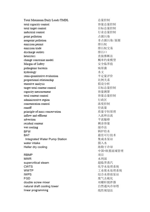
Total Maximum Daily Loads/TMDL 总量控制total capacity control 容量总量控制total target control 目标总量控制industrial control 行业总量控制point pollution 点源污染nonpoint pollution 非点源污染/面源emission permit 排污权emission trade 排污权交易discharge outlets 排污口heuristics 直接推断法change constraint model 概率约束模型Margin of Safety 安全临界值pathogenic bacteria 病原菌hydrology 水文semi-quantitative evaluation 半定量评价proportional relationship 比例关系tentative analysis 假设分析target total content control 目标总量控制capacity measurement 容量测算total content control 容量总量控制administrative region 行政区concentration control 浓度控制runoff 径流量principle of mass conservation 质量守恒原理inflow and effluent 入流和出流advection 平流输移residual content 剩余容量wet cooling 湿冷法BFW 锅炉给水BAT 最佳可行技术Integrated Water Pump Station 集成水泵站water intake 摄入水Heller dry cooling 海勒干冷却RBMP 中国-欧盟流域管理项目MWR 水利部supercritical steam 超临界蒸汽CWTS 化学水处理系统WWTP 工业废水处理系统IWPS 综合水排放泵站FGD 废气去硫化double screw mixer 双螺杆搅拌器natural draft cooling tower 自然通风冷却塔linear programming 线性规划法non-linear programming 非线性规划法integer programming 整数规划法dynamic programming 动态规划法discrete programming 离散规划法grey programming 灰色规划法fuzzy programming 模糊规划法assimilative capacity 纳污能力nominal assimilative capacity 公称纳污能力infiltration 浸渗exfiltratio 露出blow down stream 排空流discharge stream 排放流concentration gradient 浓度梯度Inflow Rate Measured on side 旁测入流量Integrated Pollutant Degradation Coefficient 污染物综合降解系数weighting generalizatio 权重概化法eutrophication 水体富营养化total emission control 污染物总量控制the total emission control of the drainage outlet 排污口总量控制the total emission control of the discharge source of the pollutants 污染物排放源总量控制2D partial differential equations 二维偏微分方程empirical expression 经验表达式linear regression 一元线性回归法CW blow down 化学水排放UF 超滤IX 离子交换RO 反渗透MB regenerate 混床再生SHE institute 苏州热工研究院CT 冷却塔CF 浓缩系数STP(sewage treatment plant)污水处理厂cavitation 穴蚀coal grinder 磨煤机classifier 分类机wet bulb temperature 湿球温度natural draft 自然通风run-off 径流SS(suspended solid)固体悬浮颗粒TKT 托克托MWR 国家水利部assimilative capacity 河流纳污能力BOD 生化需氧量river reach pollution index (RRPI) 河流深水污染指数river basin pollution index (RBPI) 流域污染指数catchment 集水biological contact oxidation 生物接触氧化pH correction/adjustment pH 调节fresh water 清水capacity 容量Geng Qing creek 庚庆沟Maobula creek 毛不拉沟Lama Bay 喇嘛湾ELS(Emission Limited Segments) 排放标准限制河段WQLS (Water Quality Limited Segments) 水质标准限制河段theory of water quality planning 水质规划理论discrete programming 离散规划法pollutant concentration 污染物浓度Integrated Pollutant Degradation Coefficient 污染物综合降解系数Diverting YR to Tianjin 引黄济津Chinese South-to-North Water Diversion Project 中国南水北调项目water balance scheme 水平衡规划ash silo 灰场the National Power Control Allocation Centre 国家电力控制和分配中心YRCC 黄河水利委员会Plate settler 斜板沉淀池EDI 电去离子器target year 水平年current year 现状年flow chart 工艺流程图Heller dry cooling 海勒式干法冷却air fin 散热片state classifier 静态分类机dynamic classifier 动态分类机grinder 碾磨机water intake 取水。
污水处理外文翻译带原文
Study on Disinfection and Anti –microbial Technologies for Drinking WaterZHU Kun, FU Xiao Yong(Dept. of Environmental Engineering, LAN Zhou Railway University, LAN Zhou 730070, China)Abstract: Disinfection by-products produced by the reaction between chlorine and dissolved organic compounds and other chemicals are considered as a worrying problem in the drinking water treatment process since a series of mutagenic carcinogen substances are formed including trihalomethanes (THMs). Among the tested disinfectants(chlorine , ozone , chlorine dioxide , potassium permanganate , chloramines and hydrogen peroxide etc. ) , chlorine dioxide has proved to be the most feasible and effective oxidant for drinking water treatment and removal of pathogens due to its oxidation efficiency , low cost and simple way of utilization. A series of experiments indicate that chlorine dioxide can significantly restrain production of trihalomethanes (THMs) and control bacteria growth particularly for Cryptosporidium oocysts. The experiments verified that both ozone and chlorine dioxide are absolutely vital to ensure thtion of water storage are destroyed. The paper discusses oxidation capacity of chlorine dioxide, especially for removing petroleum compounds, which is affected by reaction time, gas injection way, and pH of treated water.Key words: disinfection; oxidants; water treatment; pathogens; chlorine dioxideCLC number: X523 Document code: A1 IntroductionChemical and filtration processes are two main methods used in China for treating drinking water meanwhile UV radiation has been used successfully for water treatment with relatively low flow rate. On the individual family level, usually chemical treatment is a feasible alternative. The following guidelines exist for the selection of suitablal of contaminants should be done by decomposition, evaporation or precipitation etc, to eliminate or decrease the toxicity, oxidants or reactionby-products should not be harmful to human health, and the purification processes should be practical and economical. The objective of this paper is to evaluate and discuss available disinfectants for drinking water treatment. The different disinfectants are compared regarding purification efficiencies and application approaches.2 Comparison ofO3 > ClO2 > HOCl > OCl - > NHCl2 > NH2ClReferring to Fiessinger′s [2] suggestion, the properties of these disinfectants are compared in Tab. 1. Chlorine is shown to be an excellent disinfectant to prevent waterborne diseases such as typhoid fever over long periods. Chlorine reacts not only within oxidation, but also by electrophilic substitution to produce a variety of chlorinated organic by - products, particularly trihalomethanes (THMs) and other mutagens. Here THMs mainly refer to chloroform, bromoform, dibromochloromathane and bromodichloromathane etc. Since the 1970`s, the usage of Cl2 in drinking water disinfection has been questioned with ozone being substituted as the preferred disinfectant in the water supply plants. But , ozone could not be introduced to the rural farmer community due to its high costs and short half - life (15~20 min. ) . As with other disinfectants, ozonation also leads to formation of organic by - product s such as aldehyde, ketones, and carboxylic acids, and also mutagenicity may be induced if bromic anion exists.Tab. 1 Comparison of various oxidants- no effect ; + little effect ; + + effect ; + + + largest effectMany studies have pointed out that disinfection is absolutely vital to ensure that any microorganisms arising from fecal contamination of water storage are destroyed. The selection of the available disinfectant s must concern to reduce risk from microbial contamination of drinking water and the potential increase in risk from chemical contamination that result from using any of the disinfectant s. The biocidal efficiency of commonly used disinfectants - ozone, chlorine dioxide, chlorine and chloramines are ranked almost with the same order as the oxidizing capacity, but the stability of those are following the order as [3]:Chloramines > Chlorine dioxide > Chlorine > Ozone3 Purification of organic pollutants by chlorine dioxideAccording to WHO guideline for drinking water quality, much consideration should be paid to benzene homologous compounds; therefore, the study on purification effect s of chlorine dioxide is focused on petrochemical pollutants. A series of experiment s were carried out to simulate the oxidation processes of contaminated water. The polluted solutions were prepared in a dark barrel (10L capacity) of seven kinds of benzene homologous compounds-Benzene , toluene , ethyl benzene , p-phenylmethane, o-phenylmethane, m-phenylmethane and styrene. Samples were taken to determine the initial concentration of the compounds prior to the test s. Standard chlorine dioxide solution was produced from sodium chlorite reacted with HCl solution of 10% [4]. The GR - 16A Gas - chromatograph with FID detector Shenyang LZ-2000 was used for measurement of Cl2, ClO2, ClO-2 and ClO-3[5]. Oil concentrations were determined with an UV -120-20 spectrophotometer (Shimadzu) following the procedure described by APHA [4]. Organic compounds in the water samples were measured with a GC-MS (QP-1000A). ClO2and O3were standardized by iodimetric titration at pH7.For the purpose of chemical disinfection for drinking water, chlorine was instantaneously ignored due to the formation of THMs and other mutagenic substances. The results indicated that potassium permanganate and hydrogen peroxide did not have enough oxidation capability to decompose petroleum contaminant s achieving only 46 %, and 5.7% decomposition of styrene, respectively. Ozone could not be selected due to it s high cost, complex operation and short half-life although it is an excellent oxidant for water treatment. Chlorine dioxide was the next most successful alternative for disinfection. The benefit s include-effective oxidation capacity, algicidal effect and negligible formation of halogenated by-products. Based on economic and operational requirement, the mixing gas method is easily used. The results obtained suggest that disinfection of drinking water with ozone and or chlorine dioxide seems to be a suitable alternatives to the use of NaClO for cont rolling the formation of non-volatile mutagens[6].In the laboratory experiments, the oxidants ozone, chlorine dioxide, potassium permanganate and the mixing gas (mainly contained ClO2 and a certain amount of Cl2, O3 and H2O2) were tested for removal of the petroleum compounds, and results are shown in Tab. 2.Tab. 2 Comparison of oxidation capacity for the various oxidantsA study was conducted to elucidate the decay pathway of monochloramine in thepresence and absence of natural organic matter (NOM) [7]. It was found that natural organic matter acted primarily as a reductant rather than catalyst. This conclusion was verified using a redox balance, and much of oxidizing capacity of monochloramine goes towards NOM oxidation. Cleaning agents and disinfectants from house keeping, hospitals, kitchens are sources of absorbable halogenated organic compounds (AOX) in municipal wastewater. The amount of AOX generated strongly depends on the nature and concentrations of dissolved and solid organic compounds, the concentration of active substances, temperature, pH and reaction time [8] When the mixing gases react with water molecules and organic micro-pollutants, hypochlorous acid is formed by chlorine, chlorite and chlorate ions are produced from chlorine dioxide in a series of redox reactions. The principal reactions are summarized as follows:ClO2+ organic →ClO -² + oxidized organic (1)2ClO -² + Cl2 = 2ClO2 + 2Cl - (2)2ClO -²+ HOCl = 2ClO2 + 2Cl - + OH- (3)2ClO2 + HOCl + H2O = 2ClO - ³ + HCl + 2H+ (4)The rate of chlorate yield can be described by Equation (5):d [ClO3]/ d t = 2 k [ClO2] [HOCl] (5)in which k = 1.28 M/ min at 25 ℃ [9].The stoichiometry of the undesirable reactions that form chlorate in low concentration of chlorite or presents of excess chlorine is given as:ClO -² + Cl2 + H2O = ClO - ³ + 2Cl - + 2H+ (6)ClO - ² + HOCl = ClO - ³ + Cl - + H+ (7)At alkaline conditions:ClO -² + HOCl + OH- = ClO - ³ + Cl - + H2O (8)Typically, chlorine dioxide is used in drinking water treatment and the concentrations are ranging from 0.1 to 2.0 mg/L [10]. However, the relevant by - products of chlorine dioxide treatment-chlorite and chlorate have been found to induce methemoglobinemia in the human body when concentrations are more than 100 mg/L [11]. The oxidation results of the organic contaminants were affected byreaction time. The initial concentrations and removal rate at different times are listed in Tab. 3. It is shown that chlorine dioxide has a very strong oxidation capability including the break down of the benzene ring. There are no other commonly used oxidants to do like this except for ozone.Tab. 3 Removal rate of tested organic compounds at different operating time (at pH7)The injecting method for chlorine dioxide gas into the solution also has an apparent influence on the removal rate. With the indirect method, the gas firstly was dissolved in a certain amount of distilled water, and then added to the tested organic solutions, as a result, removal rates appear lower than for the direct blowing method. The main reason for the difference is due to the conversion and decomposition of chlorine dioxide in the dissolving process before the reaction. It is confirmed from Tab. 3 that the removal rate was proportional to operating time. Since chlorine dioxide showed very strong oxidation capability for organic chemicals but was reduced to chlorite anion according to Equation (4), and the removal rate initially appeared quite high. Then, chlorite keeps the oxidation capacity at a level, which allows decomposition of the organic compounds to continue even though the oxidation reaction gradually became weaker with reaction time. The experiment indicated that pH values significantly influenced the removal rate of the organic compounds. The differences of degradation rates in a variety of pH through indirect input way areshown in Tab. 4.Tab. 4 Degradation rate of benzene homologous compounds with indirect method at different pH (after 15 min)There are, however, some disadvantages with ClO2, such as easy loss from solution due to volatilization, and disproportionation above pH 10 into chlorate and chlorite ions that are of certain oxidation capacity, but reported to be harmful to health if the concentration is too high. Chlorine dioxide was unstable in the solution even though it has a stronger oxidation capability than chlorite and chlorate as the two resulted in anions being dominant in the oxidation processes. The actual concentration of chlorine dioxide depended on the existence of chlorine, chlorite and chlorate whose concentrations were determined by pH values of the solution according to Equations (6) and (8) respectively. Consequently, the pH is the critical controlling factor in the concentrations of chlorine dioxide, chlorite and chlorate. The latter two harmful ions can be removed quite quickly by treatment with a reducing agent such as sulfur dioxide - sulfite ion at pH values of 5~7[10 ,12]. Fe (II) can be used to eliminate chlorite from the water , and the redox reaction is kinetically more rapid at pH 5~7 as well[13]. It was evident that the decomposition in acidic conditions was much better than that in alkaline conditions because a disproportional amount of chlorine dioxide was consumed by the reactions under alkaline conditions. For drinking water treatment, it has been suggested that the mixture of chlorine 0.8 mg/L and chlorinedioxide 0.5 mg/L will achieve disinfection and control THMs formation in preference to use of pure chlorine dioxide[14]. According to USEPA drinking water standard, the residue of ClO2 is limited as 0.8 mg/L that tends to the goal of 0.4 mg/L.4 Control of pathogens with disinfectantsHuman pathogens that are transmitted by water including bacteria, viruses and protozoa. Organisms transmitted by water usually grow in the intestinal tract and leave the body in the feces. Thus, they are infections. Fecal pollution of water supplies may then occur, and if the water is not properly treated, the pathogens enter a new host when the water is consumed, therefore, it may be infectious even if it contains only a small number of pathogenic organisms. Most outbreaks of waterborne diseases are due to breakdowns in treatment systems or are a result of post contamination in pipelines.The microorganisms of concern are those which can cause human discomfort, illness or diseases. These microbes are comprised of numerous pathogenic bacteria, viruses, certain algae and protozoa etc. The disinfection efficiency is typically measured as a specific level of cyst inactivation. Protozoan cysts are the most difficult to destroy. Bacteria and viral inactivation are considered adequate if the requirement for cyst inactivation is met. Therefore, water quality standard for the disinfection of water have been set at microorganisms, usually take the protozoan cysts as indicator, so viruses will be adequately controlled under the same operation conditions required for inactivation of protozoan cysts. The widely found drinking water contamination is caused by protozoan that is a significant intestinal pathogens in diary cattle, likely a source of this outbreak.There are two of the most important protozoa - Cryptosporidium and Giardia cysts those are known to outbreak diseases, frequently are found in nature and drinking water storage ponds. Protozoa form protective stages like oocysts that allow them to survive for long periods in water while waiting to be ingested by a host. Protozoa cysts are not effectively removed by storing water because of their small size and density. Cryptosporidium oocysts have a setting velocity of 0.5 um/s. Therefore, if the water tank is 2 m deep, it will take the oocyst 46 days to settle to thebottom. Giardia cysts are much large and have a great settling velocity of 5.5um/s. It was evident that chlorine and chloramines were ineffective against Cryptosporidium oocysts, which was discovered to be amazingly resistant to chlorine, and only ozone and chlorine dioxide may be suitable disinfectants [15]. The investigations have verified that Cryptosporidium is highly resistant to chorine, even up 14 times as resistant as the chlorine resistant Giardia, therefore methods for removing it in past rely on sedimentation and filtration. Watson′s Law to study protozoan disinfection, reads as follows:K = Cηt (9)In the formula:K ——constant for a given microorganism exposed to a disinfectant under a fixed set of pH and temperature conditions;C ——disinfectant concentration (mg/ L);η——empirical coefficient of dilution ;t ——time required to achieve the fixed percentage inactivation.For the preoxidation and reduction of organic pollutants , the recommended dosages are between 0. 5~2. 0 mg/ L with contact time as 15~30 min depending on the pollutants characteristics in the water. In the case of post - disinfection , the safe dosages of ClO2 are 0. 2~0.4 mg/L. At these dosages, the potential by - products chlorite and chlorate do not constitute any health hazard [16]. The relation between disinfectant concentration and contact time can be established by using Ct products based on the experimental data. From this the effectiveness of disinfectants can be evaluated based on temperature, pH value and contact time. Since Cryptosporidium has become a focus of regulatory agencies in the United States and United Kingdom, the prospects of controlling this pathogen show more considerable. The comparison of the Ct values by using ozone , chlorine dioxide , chlorine and chloramines for Giardia and Cryptosporidium cyst s are listed in Tab. 5[17 ,18 ] , and for some microorganisms disinfection are displayed in Tab. 6[19 ] .Tab. 5 Ct values (mg·min/ L.) for disinfection of Giardia and Cryptosporidium cysts by using 4 disinfectantsTab. 6 Comparison of value intervals for the product Ct (mg·min/ L) for the inactivation of various microorganisms by using 4 disinfectantsThe mean Ct value for ClO2 at pH 7 and 5 ℃was 11. 9 mg·min/ L, and dropped to 5.2 at pH 7 and 25 ℃. High temperatures normally enhance the efficiency of disinfectants while lower temperatures have opposite effects requiring additional contact time or extra quantity of disinfectants. The best performance for ClO2 is at pH 9 and 25 ℃, which yields a Ct product of 2.8 mg·min/ L [20]. Chlorine dioxide appears to be more efficient for Cryptosporidium oocysts than either chlorine or monochloramine. Exposure of oocysts to 1.3 mg·min/ L at pH 7 reduces excystation from 87 % to 5 % in a hour at 25 ℃. Based on this result, Ct product of 78 mg·min/ L was calculated. However, the Ct product for ozone to do this work was examined as 5 - 10 mg·min/ L from observation that excystation decreased from 84 % to 0 % after 5 minutes with the ozone concentration of 1 mg/ L [15]. As with other disinfectants, increasing temperature decreased the Ct values and improved the cysticidal action. Increasing temperature unexpectedly reduced the Ct values from a high of 6.35 mg·min/ L at pH5 to a low of 2.91 mg·min/ L at pH 9[20]. It is generally the rule, that for protozoa ozone is the best cysticide, chlorine dioxide is superior to chlorine andiodine, but chlorine, in overall, is much superior to chloramines [21].Although disinfection efficiency of ozone is higher than chlorine dioxide, this difference can be compensated by the contact time. The experiment indicated that chlorine dioxide could reach the same results for disinfection of coliform bacteria as ozone did if time lasted long enough, which can be seen in Fig. 1. The added concentrations of both of ozone and chlorine dioxide were 2 mg/ L.Control of Cryptosporidium oocysts in potable water requires an integrated multiple barrier approach. Coagulation is critical in the effective control of Cryptosporidium by clarification and filtration. Dissolved air floatation can achieve oocysts removal of 3 logs compared to about 1 log by sedimentation. Dissolved air floatation and filtration provide two effective barriers to Cryptosporidium oocysts with cumulative log removal of 4 to 5 compared to log removals of 3 to 4 by sedimentation and filtration [22].Fig. 1 Comparison of disinfection efficiency between ozone and chlorine dioxide on coliform bacteria5 Tendency of disinfection for drinking waterIn the future, the burden of producing water with low pathogen level and low tastes and odor will be allocated to a combination of steps, including source water protection, coagulation - flocculation - sedimentation, filtration, floatation, membrane processes and adsorption. Some form of terminal treatment with chlorine, chlorine dioxide, ozone, UV, or other agents will also be required. No single step can or should be expected to shoulder the entire burden to controlling a given contaminant. With the development of techniques, new chemical and physical agents will meet tests of practicability for use in water treatment and will reduce pathogens. These may include electromagnetic fields and other forms of treatment with light or sonic energy [23].In light of availability, efficacy, operability and costs, the priority should be given to ultraviolet method among all of the currently utilized disinfection technologies, particularly in developing countries. The medium and low - pressure UV extends tremendous potential promise for adaptation into various scale water supply plants. The researches have validated that extremely low dosage of UV can behighly effective for inactivate oocysts [24]. Furthermore, comparison of medium and low - pressure lamps demonstrated no significant differences. By using low - pressure UV at the dosage of 3 , 6 and 9 mJ/ cm2 , oocyst inactivation levels were yielded between 3.4 and 3.7 log. In the trials of UV in water with turbidity of more than 1 NTU, the ability of medium –pressure was not affected, and high level of oocysts inactivation could still be achieved.6 ConclusionsTo purify drinking water, chlorine dioxide can be chosen instead of chlorine, ozone and other disinfectants because of it s advantages of high efficiency of disinfection, competent stability, low cost and simple utilizing way etc. Both ozone and ClO2 are absolutely vital to ensure that any microorganisms arising from fecal contamination of water storage are destroyed. The utilization of chlorine dioxide has been found to efficiently restrict protozoa growth, to disinfect from bacteria and viruses. Taking the protozoan cysts as indicator in which Cryptosporidium oocysts were solidly resistant to chlorine, but chlorine dioxide may be suitable disinfectants to mutilate. Thus, viruses will be adequately controlled by chlorine dioxide under the same operation conditions required for inactivation of protozoan cysts. The experiment indicated that chlorine dioxide could reach the same results for disinfection of coliform bacteria as ozone did if time lasted long enough although disinfection efficiency of ozone is higher than chlorine dioxide.It is an obvious preference for chlorine dioxide to pragmatically remove oil and benzene homologous compounds in water treatment meanwhile the formation of mutagenic and toxic substances is limited. The degradation rate was proportional to input amount of oxidants and increase of operating time. The dosage input , in overall , is suggested to range between 0. 5~2.0 mg/ L. The effective pH at which reactions occur is in the slightly acid range of 5 to 7 at which formation of chlorite and chlorate is minimized. The chlorine dioxide gas should be injected directly into the treated water body, so that high concentrations of ClO2 can be kept in the solution. Under these conditions, the elimination rate for organic pollutants will be much higher. For the storage system, input dosage of chlorine dioxide concentration should be higherthan that in laboratory studies due to complex pollutants in treated water. References:[1 ] Katz J . Ozone and chlorine dioxide technology for disinfection of drinking water [M]. Noyes New Jersey: Data Corporation, 1980.[2] Fiessinger F. Organic micropollutants in drinking water and health [M] . Publisher, N. Y., U. S. A: Elsevier Sci., 1985.[3 ] Hoff J C , Geldreich E E. Comparison of the biocidal efficiency of alternative disinfectants [C] . In Proceedings AWWA seminar, Atlanta, Georgia, 1980.[4 ] APHA , American Public Health Association. American Water Works Association and Water Pollution Control Federation. Standard Methods for the Examination of Water and Wastewater. (16th Edition) [M]. Washington D. C., 1989.[5] Dietrich A M. Determination of chlorite and chlorate in chlorinated and chloraminated drinking water by flow injection analysis and ion chromatography[J ] .A nal. Chem., 1992, 64:496 - 502.[6] Monarca S. Mutagenicity of extracts of lake drinking water treated with different disinfectants in bacterial and plant tests[J ] . Water Res, 1998, (32):2 689 - 2 695.[7] Vikesland P , Ozekin K, Valentine R L. Effect of natural organic matter on monochloramine decomposition : pathway elucidation through the use of mass and redox balance[J ] . Envi ron. Sci. Tech., 1998, 32 (10):1 409 - 1 416.[8] Schulz S , Hahn H H. Generation of halogenated organic compounds in municipal wastewater [M] . Proc. 2nd Int. Assoc. Water Qual. Int. Conf. Sewer Phys. Chem. Bio. Reactor, Aalborg, Denmark, 1998.[9 ] Aieta E M. A review of chlorine dioxide in drinking water treatment [J]. J. A WWA, 1986, 78 (6): 62 - 72.[10 ] Gordon G Minimizing chlorine ion and chlorate ion in water treatment with chlorine dioxide[J ] . J. A WWA, 1990, 82 (4):160 - 165.[11] Kmorita J D , Snoeyink V L. Monochloramine removal from water by activated carbon[J ] . J. A WWA, 1985, (1):62 - 64.[12] Gordon G, Adam I , Bubnis B. Minimizing chlorate information[J ] . J. AWWA, 1995, 87, (6): 97 - 106.[13] Iatrou A. Removing chlorite by the addition of ferrous iron[J ] . J. A WWA, 1992, 84 (11): 63 - 68.[14 ] Schalekamp Maarten. Pre - and intermediate oxidation of drinking water with ozone, chlorine and chlorine dioxide [J]. J. Ozone Science and Engineering, 1986, 8: 151 - 186[15 ] Korich D G, Mead J R , Madore M S , et al . Effects of ozone, chlorine dioxide, chlorine and monochramine on Cryptosporidium parvum oosyst viability [J]. Applied and Environmental Microbiology, 1990, 56: 1 423 - 1 428.[16 ] AWWA Research Foundation. Chlorine dioxide; drinking water issues, 2nd International Symposium [R]. Houston, TX, 1992.[17] Lykins B W, Griese H G. Using chlorine dioxide for trihalomethane control[J ] . J, A WWA, 1986, 71 (6): 88 - 93.[18] Regli S. Chlorine dioxide , drinking water issues , 2nd International Symposium [ R ] . Houston, TX, AWWA Research Foundation, 1992.[19] Hoff J C. Inactivation of microbial agents by chemical disinfectants[J] . US EPA, 1986.[ 20 ] Rubin A , Evers D , Eyman C , et al . Interaction of gerbil - cultured Giardia lamblia cysts by free chlorine dioxide [J]. Applied and Envi ronmental Microbiology, 1989, 55: 2 592 - 2 594.[ 21 ] Rusell A D , Hugo WB , Ayliffe GA J . Principes and Practice of Disinfection [M]. Preservation and Sterilization. Blackwell Scientific Publications, Oxford, U K, 1992.[22 ] Edzwald J K, Kelley M B. Control of Cryptosporidium from reservoirs to clarifiers to filters [C] . Proc. 1st IAWQ –IWSA Joint Specialist Conf. Reservoir Manage. Water Supply, Prague, Czech, 1998.[23] Haas Charles N. Disinfection in the Twenty - first century[J ] . J. A WWA, 2000, 92 (2): 72 - 73.[24 ] Clancy L , Jenneifer , Bukhari Z , et al , Using UV to Inactivate Gryptosporidium[J ] . J. A WWA, 2000, 92: 97 - 104.饮用水的消毒及杀菌技术研究朱琨伏小勇(兰州铁道学院环境工程系, 甘肃兰州730070)摘要:饮用水处理消毒过程中可产生一系列致癌物质,主要是氯与水中的有机物和其它化学成分反应的结果,其中典型产物有三氯甲烷. 通过对常用消毒剂液氯,臭氧,二氧化氯,高锰酸钾,氯胺及过氧化氢的实验对比,证明二氧化氯是高效,方便,廉价的消毒剂. 它不仅对一般病原菌类有明显的抑制和杀菌作用,对清除难以灭杀的潜原性病毒也有理想的效果. 在净化水中石油类有机物时,二氧化氯的效果受到反应时间,注入方式和pH 值的影响.关键词:消毒;氧化剂;水处理;病原菌;二氧化氯中图分类号:X523 文献标识码:A中文译文:饮用水消毒和杀菌技术的研究朱琨伏小勇(兰州铁道学院环境工程系,甘肃兰州,730070 中国)在饮用水处理过程中,通过氯与溶解性有机物和其他化合物的反应所产生的消毒副产物被看作一个令人担忧的问题,因为一系列诱变致癌的物质组成包括总卤甲烷。
(整理)污水处理英语词汇

污水处理英语词汇 AA/A/O 法anaerobic-anoxic-oxicprocess(厌氧-缺氧-好氧法)A-A-O 生物脱氮除磷工艺 A-A-O biological nitrogen andphosphorus removal process A-O 脱氮工艺 A-Onitrogen removal process A-O 除磷工艺 A-Ophosphorus removal process AB 法 Adsorption Biodegradation process(吸附生物降解法)总a 放射线 Total a radioactivity氨氮 ammonia-nitrogen 氨基酸 amino acid氨化反应 Nitragen铵盐 ammonium saltA/O 法(厌氧-好氧法)anaerobic-oxic process奥贝尔(Orbal)型氧化沟Orbal oxidation ditchB巴登福脱氮除磷工艺Bardenpho nitrogen and phosphorus removal process白水(漂洗废水) whitewater(bleaching water) 板框压滤 plate pressure filtration离心机 centrifugal machine半渗透膜semi-permeable membrane棒状杆菌属corynebacterium薄膜式淋水填料 filmpacking饱和常数(Ks) saturationconstant 暴雨公式 storm flowformula 暴雨径流 storm runoff溢流井 overflow well苯 benzene苯胺 aniline总B 放射性 Total Bradioactivity泵型叶轮暴气器 paddleimpeller aerator泵站 pumping stationBMTS 型一体化氧化沟BMTS intrachannel clarifieroxidation ditch 闭路循环 closed loop表面冲洗 surfacewashing表面负荷 surface load表面过滤 surfacefiltration 表面活性剂 surfactant表面活性物质 surface active additive agent表面曝气 surface aeration表面曝气器 surface aerator表面淹灌 surface flood irrigation表面冲洗装置 surface washing facility丙烯酸 acrylic acid 丙烯腈 acrylonitrile病毒 virus病原菌(致病菌) pathogen 病原微生物 pathogen microorganismBOD-污泥负荷BOD-sludge load补充水 make-up water 布朗运动 Brownian movement C财务评价 financial evaluation配水系统 distribution system侧渠型一体化氧化沟 integrated oxidation ditchwith side ditch产氢气乙酸菌 Rydrogenes and acetic aidgenes产甲烷细菌methanogenes产率系数 yield coefficient常规给水处理工艺 conventional water treatmentprocesses敞开式循环冷却水系统 opened recirculating coolingwater system超高纯水ultra-high-purify water超过滤 ultrafiltration超过滤膜法ultrafiltration membrane process沉淀 precipitation, sedimentation沉淀池 sedimentationtank沉砂池 grit chamber城市废水 municipalwastewater城市废水处理 municipal wastewater treatment澄清 clalification可持续发展 sustainable development充满度 degree of fullness重现期 exceedion interval, period of recurrence抽风式机械通风冷却塔 induced draft mechanical cooling tower臭氧发生器 ozone generator臭氧法 ozonation process臭氧消毒 ozonedisinfection 初次(级)沉淀池 primary clarifier, primarysedimentation tank除水器 drift eliminator除铁除锰 iron and manganese removal 除盐水(脱盐水) desalted water,demineralized water 除渣 desilication, silica removal除藻 algal removal 除氟 algal fluorine穿透曲线 penetration curve活性污泥法 activatedsludge process 生物脱氮工艺 biological nitrogen remo process船型一体化氧化沟 BoatType in intrachannelclarifier oxidation ditc纯(富)氧曝气法pure-oxygen aeration pro磁凝结 magnetic coagulation磁盘法 magnetic diskprocess 磁过滤法 magneticfierration process萃取 extraction萃取剂 extractant D 达西定律 Darcy ’s law大肠菌群Coliform-group bacteria大气泡曝气装置 large bubble aerator代谢 metabolism带式过滤 belt press filtration]单级传统消化池 single-stage conventional digester单螺旋式曝气装置single spiral aerator 氮 nitrogen氮循环 nitrogen cycle 蛋白质 protein倒虹管 inverted siphon 低放射性废物 low-level radio active waste 制浆废水 kraft mill wastewater敌百虫 dipterex敌敌畏 dichlorvos 涤纶纤维 polyester fiber地表漫流系统 overland flow system(OF)地表水 surface water地面(表)水环境质量标准 environmental quality standard for surface water地下滤场 underground filtration field地下渗漏 underground percolation地下渗滤系统 subsurface infiltrationsystem地下水 groundwater人工湿地系统artificial(constructed)wetland再生水回流地下水质标准water quality standard forrecharging parifiedwastewater water into groundwateraquifer地下水位 underground water level淀粉生产废水 starch producing wastewater点滴-薄膜式淋水填料splash-film packing点滴式淋水填料 splash packing 点污染源 pointpollufion source 电动电位electromotance potential电镀废水electroplating wastewater电极 electrode电解法 electrolyticalprocess电流密度 eletronic density电渗析 electrodialysis 电渗析器electrodialyzer电晕放电 brush discharge动态年成本 dynamic annual cost动植物油 oil and grease 对硫磷 parathion 多层床 multibed 多环芳烃 polycyclichydracarban 多氯联苯polychlorinated biphenyls(PCBs) E二次(级)沉淀池secondary clarifier, secondary sedimentation 二级处理 secondarytratament F 乏燃料 spent fuel 反冲洗 black washing反渗透(逆渗透)reverse osmosis 反渗透法 reverseosmosis process反渗透膜 reverse osmosis membrane反硝化,脱氮denitrification防止腐蚀 corrosion prevention纺丝 spining 纺织废水 textile wastewater放射性半衰期radioactive half-life放射性废水处理 radioactive wastewatertreatment放射性排出物radioactive effluent非点源污染(面源污染)non-point source pollution非离子氨 non-ionic ammonia废水处理 wastewater treatment废水中和neutralization of wastewaters分离 separation分流制 separate system分流排水系统separated sewer system酚 phenol焚烧 incineration 风吹损失 windageloss风筒式冷却塔chimmey cooling tower封闭循环系统 closedrecirculation system氟化物 fluoride辐射流沉淀池 radial flow sedimentation tank浮盖式消化池floating-cover digester气浮 flotation 福斯特利帕除磷工艺 Phostrip phosphorus removal process福列德克斯脱氮除磷工艺 Phoredox nitrogen and phosphorus removal process 腐蚀 corrosion富营养化eutrophication富营养化湖泊、水库 eutrophic lake,eutrophicreservoirGr 射线 gamma rays 甘蔗废水 sugarcanewastewater 干化 drying干化床 drying bed冷却塔 cooling tower钢铁工业废水 iron and steel mill wastewater高纯水 ultrapure water 高放废物 high-level radio active wastes高份子电解质polymolecular electrolye高份子絮凝剂polymolecular floc高负荷活性污泥法 high-loading activatedsludge method高负荷生物滤池 high loading biological filte高炉煤气洗涤水wastewater produced fromscrubbing blast furnacegas高锰酸盐指数 potassium permanganate index高速消化池 high-rate digester高梯度磁分离器(HGMS) high grade magnegic separator高浊度水 high turbiditywater 格栅 bar screen 隔板反应池 bafflereaction tank隔板式混合槽 baffle mixer隔油池 oil separator 镉 cadmium铬 chromium给水泵站 water pumping station给水处理 water treatment给水网管系统 water supply system工业水处理与循环系统industrial water treatment and recirculation system工业废水 industrial wastewater汞 mercury鼓风曝气 blast aeration 鼓风式机械通风冷却塔 forced draft mechanicalcooling tower固定螺旋式曝气装置fixed spiral aerator景观、娱乐水体landscape and recreation waterbody管道接口 conduit joint 给水配水系统 watersupply piping distribution system网管平差 balancingnetwok 罐头生产废水 Cannerywastewater硅藻土 cilicious mar H海水淡化demineralization of sea water含酚废水 phenol contained wastewater含水量 moisture content含盐量 saline capacity 含油废水 oily wastewater旱流污水量(DWF)dry-weather flow 好氧生物处理 aerobicbiological treatment 好氧塘 aerobic pond 好氧稳定 aerobic stabilization合成洗涤剂 synthetic detergent合成纤维 synthetic fiber合成纤维废水 synthetic fiber wastewater 合成橡胶 synthetic rubber合流城市废水 combinedmunicipal wastewater合流制排水系统combined sewer system水体功能分类 waterbodyfunction classification核能工厂 nuclear power station核燃料循环 nuclear fuel cycle核素 nuclide冶金工业废水metallurgical industrywastewater黑液 black liquor 黑液除硅sillica-elimination fromblack liquid虹吸滤池 siphon filter 化学处理 chemicaltreatment化学工业 chemicalindustry化学吸附 chemicaladsorption 化学纤维 chemical fiber化学需氧量 chemicaloxygen demand (COD)环状管网系统 grid pipe network system缓蚀 corrosion inhibition缓蚀剂 corrosion inhibitor磺化煤 sulfonated coal 挥发酚 volatile phenol 回流比 recycle ratio 回流污泥率 return sludge ratio汇水面积 catchment area, collection area混合 mixing混合床 miced bed 混合液挥发性悬浮固体mixed liquor volatile suspended solids(MLVSS) 混合液悬浮固体 mixed liquor suspended solids(MLSS)混凝 coagulation 混凝沉淀coagulation-sedimentation 混凝剂 coagulant 浑浊度 tubidity活化产物 activation products硅酸钠 sodium silicate 活性剂 activator活性染料 active dye 活性炭 activated carbon活性炭的再生re-generation of activated carbon活性炭吸附 activecarbon adsorption活性污泥 activated sludge 活性污泥法 activatedsludge process 活性污泥负荷 activatedsludge loading活性污泥驯化acclimation of activatedsludge J机械反应池 mechanicalreactor机械剪切曝气装置mechanical shearing aerator机械搅拌 mechanicalmixing机械搅拌澄清池accelerator机械曝气 mechanicalaeration机械通风冷却塔mechanical draft cooling tower 机械脱水 mechanicaldewatering极化现象 polarization级配 granularcomposition集水池 collection well集中处理(合并处理)joint treatment计算机 computer 计算机辅助设计computer aid design加速过滤器accelo-filter加压气化 pressure-gasification甲基对硫磷 parathion methyl甲醛 formaldehyde甲烷 methane甲烷发酵 methane fermentation 甲烷气体 methane gas间歇式活性污泥系统sequencing batch reactoractivated sludge system(蒹性塘 facultative pond检查井 manhole 减压薄膜蒸发法decreasing pressure andthin-film evaporation process碱法制浆 soda pulping process浆粕 pulp降雨历时 duration of rainfall降雨量,降水precipitation浇洒道路用水 street flushing water焦化废水 coking wastewater交替工作式氧化沟alternative operating oxidation ditch交替运行的生物滤池alternative operating trickling filter胶体 colloid阶段曝气 step aeration 接触池 contact chamber 接触氧化法 contactoxidation process 结垢 scale节水 water saving 锦纶纤维 polyamide fiber腈纶纤维 acrylic fiber 精制塘(深度处理塘) polishing pond经济效益 economic benefit径流系数 runoff coefficent静态年成本 static annuity cost景观娱乐用水水质标准 water quality standard forlandscape and recreation area酒精工业 alcoholdistilery就地处理系统(小型处理)on-site treatment systems(small scale facilities)聚丙烯酰胺polyacrylamide聚丙烯酰胺水解体polyacrylamide hydrolysis product聚合 polymerize聚合度 polymerizingdegree聚合氯化铝polyaluminum chloride均衡池(塘) equalizaliontank(basin,lagoon)K卡罗塞式氧化沟Corrousel oxidation ditchK 型叶轮曝气机 K type impeller aerator凯式氮 kjeldahlnitrogen空气驱动式生物转盘aero biological disks孔隙率 porosity快滤池 rapid filter快速渗滤系统 rapid infiltration system(RI) 矿井 shaft(mine)矿区 mining area 矿区环境 mining area environment 矿山废水 minery wasterwater矿山酸性废水 acid minewastewater 扩散板 diffusion plate扩散管 diffusion tube扩散盘(罩) diffusion disc(cover) L乐果 dimethoate冷凝 condensation 冷凝水 condensate water 冷却 cooling冷却池 cooling pond 冷却塔 cooling tower 冷却塔配水系统 coolingtower distribution system 冷却循环水 circulated cooling water冷轧 cold steel -rolling离心泵 centrifugal pump 离心 centrifugation force离心机 centrifugal machine离心脱水 centrifugal dewatering离心作用centrifugation离子交换 ion exchange离子交换剂 ion exchanger离子交换膜 ion exchangemembrane离子交换树脂 ion exchange resin粒径 grain size砾石承托层 gravel support炼钢厂废水steel-making process wastewater炼铁 iron-smelting 炼铁(高炉)废水 blast furnace wastewater炼油厂废水 refineryprocessing waserwater淋滤 leaching淋水密度 waterdrenching density淋水面积 waterdrenching aera淋水填料 packing磷 phosphorus 磷酸盐 phosphate生物流化床 Biologicalfluidized bed硫化物 sulphide硫化物沉淀法 precipitation with sulphide硫酸铵 ammonium sulfate硫酸钙 Calcium sulfate 硫酸铝 aluminum sulfate 硫酸镁 magnesiumsulfate硫酸铁 ferric sulfate 硫酸亚铁 ferrous sulfate硫酸盐 sulfate 硫循环 sulphur cycle 铝酸钠 sodium aluminate 滤层 filter layer滤池冲洗水量 filter washing water consumptio滤池配水系统 filterunderdrain system滤池运行周期 filtercycle time滤床 filter bed 滤料 filtering medium滤速 filtration rate 滤液 filtrate 氯 chlorine氯-氨法chlorine-ammonia process氯化,加氯处理 chlorination氯化物 Chlorides螺旋桨式快速搅拌机 propeller-type high speeagitatorM马拉硫磷 malathion脉冲澄清池 pulsator慢滤池 slowfilter慢速渗滤系统 slow rate infiltration system (SR) 煤气 coal gas 煤气厂 gas work煤气发生器 coal gas generator煤气发生站 gasgeneration station 煤气净化 coal gas purification煤炭 coal 锰 manganse米门公式 Michaelis - Menten equation莫诺德公式 Monod equation密闭式循环冷却水系统closed recirculating cooling water system密集多喷嘴曝气装置compact multinozzle aerator 面污染源 non-point pollution source敏感性分析 sensitivity analysis膜分离装置 membrane seperator膜选择性 membrane selectivity膜污染 membrane foulting膜中毒 membrane poisoningN难生物降解有机物nonbiodegradable organies 尼龙 nylon逆流漂洗counter-current washing 逆流式冷却塔counterflow cooling tower逆流再生counter-current regeneration粘胶 rayon酿酒废水 winery wastewater酿造与发酵工业废水 brewery and fermentation industrial wastewater凝结 coagulation凝结剂 coagulant牛奶生产废水 dairywastewater 浓缩 concentration浓缩倍数 cycle of concentration浓缩池 thickening tank浓缩污泥 concentrated sludge农田灌溉水质标准 standards for irrigationwater quality农用污泥中污染物控制标准 contaminants controlstandard for sludge farm农药 pesticide 农药厂废水 pesticideplant wastewaterP排泥系统 sludge - discharge system排水量 discharge排水管 drain pipe排水口 outlet排水系统 sewer system排污 blowdown泡沫分离 foam phaseseparation配水网管 distributionsystem ,pipe system 喷灌 spray irrigation喷水池 spray pond 皮革 leather 啤酒废水 brewery wastewater啤酒废水处理 brewery wastewater treatment漂白 bleaching平板式膜 plate membrane平板式叶轮曝气器 plate impellar aerator平衡吸附容量equilibrium adsorption capacity平流式沉砂池 horizontal flow grlt removal tank平流式沉淀池horizontal flow sedimentation tank 普通生物滤池biological filter,trickling filter曝气 aeration曝气沉砂池 aerationgrit chamber曝气池 aeration tank曝气栅 aeration boom曝气设备 aerationequipment曝气时间 aeration time曝气装置,曝气机aerator居民生活垃圾 HouseholdWaste庫底平整線 bottom flattingline of the site庫區填埋邊線 landfill sideline of the site庫容 Storage capacity垃圾 Waste ,Solid Waste 垃圾壩 waste dam 垃圾殘渣 residue垃圾槽 waste chute 垃圾層 waste layer 垃圾產量 Waste output垃圾堆肥場 waste compostingfield 垃圾堆體 waste pile 垃圾副壩 secondary waste dam 垃圾揀選場 Waste Sorting Site垃圾氣化 waste gasification垃圾采集車 waste collector垃圾桶 garbage ,rubbishbarrel垃圾箱 garbage container 垃圾壓實系統 wastecompactor system垃圾衍生燃料 Refuse-derivedfuel (RDF)垃圾衍生燃料 waste derivedfuel垃圾轉運車 waste transfer truck垃圾轉運站 waste transferstation垃圾裝卸坡 waste loadingramp離心脫水機 centrifugaldewaterer鈉基膨潤土 sodium bentonite農業廢棄物 AgriculturalWaste 濃縮池 thickening tank 排放 discharge排泥閥 sludge valve排水口 Drain Outlet 膨潤土 bentonite熱解 Pyrolysis 溶解氧測定儀(DO 計) dissolved oxygen meter (DO meter ) 砂水分離機 grit-water splitter 商業垃圾 Commercial Waste 上橫沖填埋場 ShanghengchongLandfill Site上清液 supernatant liquor設備選型 Type selection of equipment 滲濾液(垃圾滲濾液) leachate 滲濾液處理 leachatetreatment滲濾液處理站 Leachate Treatment Station滲濾液采集及導排氣系統平面圖 Plan of Leachate Collection and Guiding a Exhaust System 滲濾液采集盲溝 blind drain for leachate collection精品文档精品文档 生活垃圾 Domestic waste 生活垃圾焚燒污染控制標准 Standard for Pollution Control on the Municipal Solid Waste Incineration 剩余污泥 excess sludge 剩余污泥泵 excess sludge pump 輸渣機 clinker conveyer 豎向石籠 vertical stone cage雙層防滲結構 double-linersystem水位 water level提升泵站 lift pumpingstation填埋(垃圾) Landfill填埋場 Landfill site填埋場封場 seal of landfillsite填埋場總體布置圖 GeneralLayout of Landfill Site填埋場縱斷面示意圖 SketchMap of Landfill Site VerticalSection填埋庫區 Landfill Area填埋庫區平面布置圖 PlaneLayout of Landfill Area1:1000填埋氣 Landfill gas砼 concrete圖例 legend土工合成材料黏土墊層Geosynthetics Clay Liner(GCL)土工膜 geomembrane脫水機 dewaterer脫水機房 dewatering house衛生填埋 sanitary landfill渦流沉砂池(旋流沉砂池)vortex grit tank污泥泵房 sludge pumping room污泥處理 sludge treatment污泥處理流程示意圖 FlowChart of Sewage TreatmentProcess污泥管線 sludge pipeline 污泥濃度計(MLSS 計) sludge concentration meter (MLSS meter ) 污泥濃縮及脫水機房 Sludge Thickening & Dewatering House污泥脫水車間 sludge dewatering workshop 污水泵 sewage pump 污水處理 sewage treatment 污水處理厂 Wastewater Treatment Plant 污水處理流程示意圖 Sewage Treatment Process Sketch Map 污水管線 sewage pipeline 污水水面 wastewater surface 無線傳輸 wireless transmission 吸水井 suction well 消毒池 disinfecting tank 新聯村熊家窯 Xiongjiayao, Xinliancun 序批式活性污泥法(SBR 法) Sequence Batch Reactor 選型 Type selection 壓縮式垃圾車 waste compactors 厭氧、缺氧、好氧 Anaerobic, Anoxic, Aerobic Underwater Blender 厭氧堆肥 anaerobic composting 厭氧發酵 methane fermentation; anaerobic fermentation 厭氧流化床反應器 anaerobic fluidized bed 厭氧流化床反應器 anaerobic fluidized bed 氧化溝 oxidation ditch 氧化溝 oxidation ditch 葉輪曝氣機 impeller aerator 一級發酵(初級發酵) primary fermentation醫院垃圾 Hospital Waste 營養土層 nutritious soil layer預留垃圾綜合利用生產用地Reserved Waste Comprehensive Utility and Production L再生 reclamation 柵渣 sediment 黏土層 clay layer 支盲溝 blind sub-drain 至垃圾填埋場 to the waste landfill site 終期覆土 terminal earth covering 主盲溝 main blind drain 自控系統 autonomous system 自然土層 natural soil layer。
污水处理工艺中常用的名词术语及它们的英文缩写
污水处理工艺中常用的名词术语及它们的英文缩写污水处理工艺中常用的名词术语及它们的英文缩写给排水常用名词中英文对照1、给水工程 water supply engineering 原水的取集和处理以及成品水输配的工程.2、排水工程 sewerage ,wastewater engineering 收集、输送、处理和处置废水的工程.3、给水系统 water supply system 给水的取水、输水、水质处理和配水等设施以一定方式组合成的总体.4、排水系统sewerage system 排水的收集、输送、水质处理和排放等设施以一定方式组合成的总体.5、给水水源 water source 给水工程所取用的原水水体.6、原水raw water 由水源地取来的原料水.7、地表水surface water 存在于地壳表面,暴露于大气的水.8、地下水ground water 存在于地壳岩石裂缝或工壤空隙中的水.9、苦咸水(碱性水) brackish water ,alkaline water 碱度大于硬度的水,并含大量中性盐,PH值大于7.10、淡水fresh water 含盐量小于500mg/L的水.11、冷却水cooling water 用以降低被冷却对象温度的水.12、废水wastewater 居民活动过程中排出的水及径流雨水的总称.它包括生活污水、工业废水和初雨径流以及流入排水管渠的其它水.13、污水sewage ,wastewater 受一定污染的来自生活和生产的排出水.14、用水量 water consumption 用水对象实际使用的水量.15、污水量 wastewater flow ,sewage flow 排水对象排入污水系统的水量.16、用水定额 water flow norm 对不同的排水对象,在一定时期内制订相对合理的单位排水量的数值.17、排水定额 wastewater flow norm 对不同的排水对象,在一定时期内制订相对合理的单位排水量的数值.18、水质water quality 在给水排水工程中,水的物理、化学、生物学等方面的性质.19、渠道 channel ,conduit 天然、人工开凿、整治或砌筑的输水通道.20、泵站pumping house 设置水泵机组、电气设备和管道、闸阀等的房屋.21、泵站 pumping station 泵房及其配套设施的总称.22、给水处理 water treatment 对不符合用不对象水质要求的水.进行水质改善的过程.23、污水处理 sewage treatment ,wastewater treatment 为使污水达到排水某一水体或再次使用的水质要求,对其进行净化的过程.24、废水处理 wastewater disposal 对废水的最终安排.一般将废水排入地表水体、排放土地和再次使用等.25、格栅 bar screen 一种栅条形的隔污设备,用以拦截水中较大尺寸的漂浮物或其他杂物.26、曝气aeration 水与气体接触,进行溶氧或散除水中溶解性气体和挥发性物质的过程.27、沉淀 sedimentation 利用重力沉降作用去除水中杂物的过程.28、澄清clarification 通过与高浓度沉渣层的接触而去除水中杂物的过程.29、过滤filtration 借助粒状材料或多孔介质截除水中质物的过程.30、离子交换法ion exchange 采用离子交换剂去除水中某些盐类离子的过程.31、氯化chlorination 在水中投氯或含氯氧化物方法消灭病原体的过程.32、余氯residual chlorine 水中投氯,经一定时间接触后,在水中余留的游离性氯和结合性氯的总和.33、游离性余氯 free residual chlorine 水中以次氯酸和次氯酸盐形态存在的余氯.34、结合性余氯 combinative residual chlorine 水中以二氯胺和一氯胺形态存在的余氯.35、污泥sludge 在水处理过程中产生的,以及排水管渠中沉积的固体与水的混合物或胶体物.36、污泥处理sludge treatment 对污泥的最终安排.一般将污泥作农肥、制作建筑材料、填埋和投弃等.37、水头损失head loss 水流通过管渠、设备和构筑物等所引起的能量消耗.给水工程中系统和水量方面的术语1、直流水系统 once through system 水经过一次使用后即行排放或处理后排放的给水系统.2、复用水系统 water reuse system 水经重复利用后再行排放或处理后排放的给水系统.3、循环水系统 recirculation system 水经使用后不予排放而循环利用或处理后循环利用的给水系统.4、生活用水 domestic water 人类日常生活所需用的水.5、生产用水 process water 生产过程所需用的水.6、消防用水 fire demand 扑灭火灾所需用的水.7、浇洒道路用水 street flushing demand ,road watering 对城镇道路进行保养、清洗、降温和消尘等所需用水.8、绿化用水 green belt sprinkling ,green plot sprinkling 对市政绿地等所需用的水.给水工程取水构筑物的术语1、管井 deep well ,drilled well 井管从地面打到含水层,抽取地下水的井.2、管井滤水管 deep well screen 设置在管井动水位以下,用以从含水层中集水的有缝隙或孔隙的管段.3、管井沉淀管 grit compartment 位于管井最下部,用以容纳进入井内的沙粒和从水中析出的沉淀物的管段.4、大口井 dug well ,open well 由人工开挖或沉井法施工,设置井筒,以截取浅层地下水的构筑物.5、井群 batter of wells 数个井组成的群体.6、渗渠 infiltration gallery 壁上开孔,以集取浅层地下水的水平管渠.7、地下水取水构筑物反滤层 inverted layer 在大口井或渗渠进水处铺设的粒径沿水流方向由细到粗的级配砾层(简称反滤层)8、泉室 spring chamber 集取泉水的构筑物.9、进水间 intake chamber 连接取水管与吸水井、内设格栅或格网的构筑物.10、格网 screen 一种网状的用以拦截水中较大尺寸的漂浮物、水生动物或其他污染物的拦污设备.其网眼尺寸较格栅为小.11、吸水井 suction well 为水泵吸水管专门设置的构筑物.给水工程中净水构筑物的术语1、净水构筑物purification structure 以去除水中悬浮固体和胶体杂质等为主要目的的构筑物的总称.2、投药 chemical dosing 为进行水处理而向水中加一定剂量的化学药剂的过程.3、混合mixing 使投入的药剂迅速均匀地扩散于被处理水中以创造良好的凝聚反应条件的过程.4、凝聚 coagulation 为了消除胶体颗粒间的排斥力或破坏其亲水性,使颗粒易于相互接触而吸附的过程.5、絮凝flocculation A、完成凝聚的胶体在一定的外力扰动下相互碰撞、聚集以形成较大絮状颗粒的过程.曾用名反应. B、高分子絮凝剂在悬浮固体和胶体杂质之间吸附架桥的过程.6、自然沉淀 plain sedimentation 不加注任何凝聚剂的沉淀过程.7、凝聚沉淀coagulation sedimentation 加注凝聚剂的沉淀过程.8、凝聚剂 coagulant 在凝聚过程中所投加的药剂的统称.9、助凝剂 coagulant aid 在水的沉淀、澄清过程中,为改善絮凝效果,另设加的辅助药剂.10、药剂固定储备量standby reserve 为考虑非正常原因导致药剂供应中断,而在药剂仓库内设置的在一般情况下不准动用的储备量.简称固定储备量.11、药剂周转储备量 current reserve 考虑药剂消耗与供应时间之间差异所需的储备量.简称周转储备量.12、沉沙池(沉砂池)desilting basin ,grit chamber 去除水中自重很大、能自然沉降的较大粒径沙粒或杂粒的水池.13、预沉池pre-sedimentation tank 原水中泥沙颗粒较大或浓度较高时,在进行凝聚沉淀处理前设置的沉淀池.14、平流沉淀池 horizontal flow sedimentation tank 水沿水平方向流动的沉淀池.15、异向流斜管 (或斜板)沉淀池 tube(plate)settler 池内设置斜管(或斜板),水自下而上经斜管(或斜板)进行沉淀,沉泥沿斜管(或斜板)向下滑动的沉淀的池.16、同向流斜板沉淀池lamella 池内设置斜板,沉淀过程在斜板内进行,水流与沉泥均沿斜板向下流动的沉淀池.17、机械搅拌澄清池accelerator 利用机械使水提升和搅拌,促使泥渣循环,并使原水中固体杂质与己形成的泥渣接触絮凝而分离沉淀的水池.18、水力循环澄清池circulator clarifier 利用水力使水提升,促使泥渣循环,并使原水中固体杂质与己形成的泥渣接触絮凝而分离沉淀的水池.19、脉冲澄清池 pulsator 悬浮层不断产生固周期性的压缩和膨胀,促使原水中固体杂质与己形成的泥渣进行接触凝聚页分离沉淀的水池.20、悬浮澄清池 sludge blanket clarifier 加药后的原水由上通过处于悬浮状态的泥渣层,使水中杂质与泥渣悬浮层的颗粒碰撞凝聚而分离沉淀的水池.21、液面负荷 surface load 在沉淀池、澄清池等沉淀构筑物的净化部分中,单位液(水)面积所负担的出水流量.其计量单位通常以m3/(m2.h)表示.22、气浮池 floatation tank 运用絮凝和浮选原理使液体中的杂质分离上浮而去除的池子.23、气浮溶气罐dissolved air vessel 在气浮工艺中,水与空气在有压条件下相互溶合的密闭容器.简称溶气罐.24、清水池 clear-water reservoir 为贮存水厂中净化后的清水,以调节水厂制水量与供水量之间的差额,并为满足加氯接触时间而设置的水池.给水工程中输配水管网的术语1、配水管网 distribution system ,pipe system 将水送到分配管网以至用户的管系.2、环状管网pipe network 配水管网的一种置形式,管道纵横相互接通,形成环状.3、枝状管网branch system 配水管网的一种布置形式,干管和支管分明,形成树枝状.4、水管支墩 buttress ,anchorage 为防止由管内水压引起的水管配件接头移位而造成漏水,需在水管干线适当部位砌筑的墩座.简称支墩.排水工程中排水制度和管渠附属构筑物的术语及其涵义1、排水制度 sewer system 在一个地区内收集和输送废水的方式.它有合流制和分流制两种基本方式.2、合流制 combined system 用同一种管渠分别收集和输送废水的排水的方式.3、分流制 separate system 用不同管渠分别收集和输送各种污水、雨水和生产废水的排水的方式.4、检查井manhole 排水管渠上连接其他管渠以及供养护工人检查、清通和出入管渠的构筑物.5、跌水井 drop manhole 上下游管底跌差较大的检查井.6、事故排出口 emergency outlet 在排水系统发生故障时,把废水临时排放到天然水体或其它地点去的设施.7、曝雨溢流井 (截留井)storm overflow well ,intercepting well 合流制排水系统中,用来截留、控制合流水量的构筑物排水工程中水和水处理的术语及其涵义1、生活污水 domestic sewage ,domestic wastewater 居民中日常生活中排出的废水.2、工业废水 industrial wastewater 生产过程中排出的水.它包括生产废水和生产污水.3、生产污水polluted industrial wastewater 被污染的工业废水.还包括水温过高,排入后造成热污染的工业废水.4、生产废水 non-polluted industrial wastewater 未受污染或受轻微污染以及水温稍有升高的工业废水.5、城市污水 municipal sewage ,municipal wastewater 排入城镇污水系统的污水的统称.在合流制排水系统中,还包括生产废水和截留的雨水.6、旱流污水dry weather flow 合流制排水系统在晴天时输送的污水.7、水体自净 self-purification of water bodies 河流等水体在自然条件的生化作用下,有机物降解,溶解氧回升和水体生物群逐渐恢复正常的过程.8、一级处理 primary treatment 去除污水中的漂浮物和悬浮物的净化过程,主要为沉淀.9、二级处理secondary treatment 污水经一级处理后,用生物处理方法继续除去污水不胶体和溶解性有机物的净化过程.10、生物处理 biological treatment 利用微生物的作用,使污水中不稳定有机物降解和稳定的过程.11、活性污泥法 activated sludge process 污水生物处理的一种方法.该法是在人工充氧条件下,对污水和各微生物群体进行连续混和培养,形成活性污泥.利用活性污泥的生物凝聚、吸附和氧化作用,以分解去除污水中的有机污染物.然后使污泥与水分离,大部分污泥再回流到曝气池,多余部分则排出活性污泥系统.12、生物膜法 biomembrance process 污水生物处理的一种方法.该法采用各种不同载体,通过污水与载体的不断接触,在载体上繁殖生物膜,利用膜的生物吸附和氧化作用,以降解去除污水中的有机污染物,脱落下来的生物膜与水进行分离.13、双层沉淀池(隐化池) Imhoff tank 由上层沉淀槽和下层污泥消化室组成.14、初次沉淀池primary sedimentation tank 污水处理中第一次沉淀的构筑物,主要用以降低污水中的悬浮固体浓度.15、二次沉淀池secondary sedimentation tank 污水生物处理出水的沉淀构筑物,用以分离其中的污泥.16、生物滤池 biological filter ,trickling filter 由碎石或塑料制品填料构成的生物处理构筑物.污水与填料表面上生长的微生物膜间歇接触,使污水得到净化.17、生物接触氧化bio-contact oxidation 由浸没在污水中的填料和人工曝气系统构成的生物处理工艺.在有氧的条件下,污水与填表面的生物膜反复接触,使污水获得净化.18、曝气池aeration tank 利用活性污泥法进行污水生物处理的构筑物.池内提供一定污水停留时间,满足好氧微生物所需的氧量以及污水与活性污泥充分接触的混合条件.排水工程中污泥和污泥处理的术语及其涵义1、原污泥 raw sludge 未经污泥处理的初沉污泥、二沉剩余污或两者的混合污泥.2、初沉污泥 primary sludge 从初次沉淀池排出的沉淀物.3、二沉污泥 secondary sludge 从二次沉淀池排出的沉淀物.4、活性污泥activated sludge 曝气池中繁殖的含有各种好氧微生物群体的絮状体.5、消化污泥digested sludge 经过好氧消化或厌氧消化的污泥,所含有机物质浓度有一定程度的降低,并趋于稳定.6、回流污泥 returned sludge 由于次沉淀池(或沉淀区)分离出来,回流到曝气池的活性污泥.7、剩余污泥 excess activated sludge 活性污泥系统中从二次沉淀池(或沉淀区)排出系统外的活性污泥.8、污泥气 sludge gas 在污泥厌氧消化时,有机物分解所产生的气体.主要成分为甲烷和二氧化碳,并有少量的氢、氮和硫化氢.俗称沼气.9、污泥消化sludge digestion 在有氧或无氧条件下,利用微生物的作用,使污泥中有机物转化为较稳定物质的过程.10、好氧消化aerobic digestion 污泥经过较长时间的曝气,其中一部分有机物由好氧微生物进一步降解和稳定的过程.11、厌氧消化 anaerobic digestion 在无氧条件下,污泥中的有机物由厌氧微生物进行降解和稳定的过程.12、中温消化mesophilic digestion 污泥在温度为33℃-35℃时进行的厌氧消化工艺.13、高温消化thermophilic digestion 污泥在温度为53℃-55℃时进行的厌氧消化工艺.14、污泥浓缩sludge thickening 采用重力或气浮法降低污泥含水量,使污泥稠化的过程.15、污泥淘洗 elutriation of sludge 改善污泥脱水能的一种污泥预处理方法.用清水或废水淘洗污泥,降低水化污泥碱度,节省污泥处理投药量,提高污滤脱水效率.16、污泥脱水 sludge dewatering 对浓缩污泥进一步去除一部分含水量的过程,一般指机械脱水.17、污泥真空过滤 sludge vacuum filtration 利用真空使过滤介质一侧减压,介质的污泥脱水方法.18、污泥压滤 sludge pressure filtration 采用正压过滤,使污泥水强制滤过介质的污泥脱水方法.19、污泥干化 sludge drying 通过渗滤或蒸发等作用,从污泥中去除大部分含水量的过程,一般指采用污泥干化场(床)等自然蒸发设施.20、污泥焚烧sludge incineration 污泥处理的一种工艺.它利用焚烧炉将脱水污泥加温干燥,再用高温氧化污泥中的有机物,使污泥成为少量灰烬.排水工程中物理量的术语及其涵义1、生化需氧量 biochmical oxygen demand 水样在一定条件下,于一定期间内(一般采用5日、20℃)进行需氧化所消耗的溶解氧量.英文简称BOD.2、化学需氧量 chemical oxygen demand 水样中可氧化物从氧化剂重铬酸钾中所吸收的氧量.英文简称COD.3、耗氧量oxygen consumption 水样中氧化物从氧化剂高锰酸钾所吸收的氧量.英文简称OC或CODMn .4、悬浮固体suspended solid 水中呈悬浮状态的固体,一般指用滤纸过滤水样,将滤后截留物在105℃温度中干燥恒重后的固体重量.英文简称SS。
中英文 污水处理和垃圾填埋词汇

中英文污水处理和垃圾填埋词汇HDPE穿孔管HDPE perforated pipe表面排水沟surface drain表曝机surface aerator厂区factory area;plant area(污水处理厂厂区)场区道路plant road车位truck space沉降Settlement陈家冲填埋场Chenjiachong Landfill Sitexxbearing capacity城市固体废弃物municipal solid waste城市生活固体废物,城市生活垃圾Municipal Solid Waste (MSW)城市生活垃圾卫生填埋技术规范TechnicalCodeforSanitaryLandfillofMunicipalSolidWaste出水水质effluent quality挡土墙retaing wall地磅房及传达室Weighbridge Room andReception Room调节xxadjusting tank动态发酵dynamic fermentation二沉池secondary sedimentation tank二次沉淀池secondary sedimentation tank二级发酵(次级发酵)secondary fermentation防渗材料impervious materials防渗层liner废塑料、废纸、废织物、草木树叶和厨余waste plastics、waste paper, waste fabric, plant,kitchen residue and sweeping焚烧Incineration焚烧炉incinerator腐熟度putrescibility基膨润土calcium bentonite高密度聚乙烯HDPE工程量清单Bill of Quanties工业固体废物,工业垃圾Industrial Solid Waste工艺流程图process flowchart固体废物Solid Waste固体废物的管理,垃圾管理Solid Waste Management, SWM刮泥机sludge scraper管理区Management Area横向导气软管transverse gas tube灰渣ash residue回流污泥returned sludge回流污泥泵return sludge pump混凝土穿孔管concrete perforated pipe混凝土路面concrete road混凝土心墙concrete wall加油站Gas Station家庭垃圾household garbage家庭垃圾的分拣;家庭垃圾的分类sorting of household waste 建筑垃圾Construction Waste浆砌块石stone blocks with cement mortar搅拌器blender截洪沟flood intercepting trench截污坝pollutant intercepting dam进场道路Access road进水泵房inflowpumping room进水水质inflow water quality静态发酵static fermentation居民生活垃圾Household Waste库底平整线bottom flatting line of the site库区填埋边线landfill side line of the site库容Storage capacity垃圾Waste,Solid Waste垃圾坝waste dam垃圾残渣residue垃圾槽waste chute垃圾层waste layer垃圾产量Waste output垃圾堆体waste pile垃圾副坝secondary waste dam垃圾拣选场Waste Sorting Site垃圾气化waste gasification垃圾收集车waste collector垃圾桶garbage,rubbish barrel垃圾箱garbage container垃圾衍生燃料Refuse-derived fuel (RDF) 垃圾衍生燃料waste derived fuel垃圾转运车waste transfer truck垃圾转运站waste transfer station垃圾装卸坡waste loading ramp离心脱水机centrifugal dewater钠基膨润土sodium bentonite农业废弃物Agricultural Waste浓缩xxthickening tank排放discharge排泥阀sludge valve排水口Drain Outlet膨润土bentonite热解Pyrolysis溶解氧测定仪(DO计)dissolved oxygen meter(DO meter)砂水分离机grit-water splitter商业垃圾Commercial Waste上横冲填埋场ShanghengchongLandfill Site上清液supernatant liquor设备选型Type selection of equipment渗滤液(垃圾渗滤液)leachate渗滤液处理leachate treatment渗滤液处理站Leachate Treatment Station渗滤液收集及导排气系统平面图PlanofLeachateCollectionandGuidingandExhaustSystem渗滤液收集盲沟Blind drain for leachate collection生活垃圾Domestic waste生活垃圾焚烧污染控制标准Standard for Pollution Control on the Municipal Solid WasteIncineration剩余污泥excess sludge剩余污泥泵excess sludge pump输渣机clinker conveyer竖向石笼vertical stone cage双层防渗结构double-liner system水位water level提升泵站lift pumping station填埋(垃圾)Landfill填埋场Landfill site填埋场封场seal of landfill site填埋场总体布置图General Layout of Landfill Site填埋场纵断面示意图Sketch Map of Landfill Site Vertical Section填埋库区Landfill Area填埋库区平面布置图Plane Layout of Landfill Area 1:1000填埋气Landfill gas砼concrete图例legend土工合成材料粘土垫层Geosynthetics Clay Liner (GCL)土工膜geomembrane脱水机dewater脱水机房dewatering house卫生填埋sanitary landfill涡流沉砂池(旋流沉砂池)vortex grit tank污泥泵房sludge pumping room污泥处理sludge treatment污泥处理流程示意图Flow Chart of Sewage Treatment Process污泥管线sludge pipeline污泥浓度计(MLSS计)sludge concentration meter(MLSS meter)污泥浓缩及脱水机房Sludge Thickening & Dewatering House污泥脱水车间sludge dewatering workshop污水泵sewage pump污水处理sewage treatment污水处理厂Wastewater Treatment Plant污水处理流程示意图Sewage Treatment Process Sketch Map污水管线sewage pipeline污水水面wastewater surface无线传输wireless transmission吸水井suction well消毒池disinfecting tank新联村熊家窑Xiongjiayao, Xinliancun序批式活性污泥法(SBR法)Sequence Batch Reactor选型Type selection厌氧发酵methane fermentation; anaerobic fermentation厌氧流化床反应器anaerobic fluidized bed厌氧流化床反应器anaerobic fluidized bed氧化沟oxidation ditch氧化沟oxidation ditch叶轮曝气机impeller aerator一级发酵(初级发酵)primary fermentation医院垃圾Hospital Waste营养土层nutritious soil layer预留垃圾综合利用生产用地ReservedWasteComprehensiveUtilityandProductionLand再生reclamation栅渣sediment粘土层clay layer支盲沟blind sub-drain至垃圾填埋场to the waste landfill site终期覆土terminal earth covering主盲沟main blind drain自控系统autonomous system自然土层natural soil layer。
水处理常用名词中英文对照
水处理常用名词中英文对照1、给水工程water supply engineering原水的取集和处理以及成品水输配的工程。
2、排水工程sewerage ,wastewater engineering收集、输送、处理和处置废水的工程。
3、给水系统water supply system给水的取水、输水、水质处理和配水等设施以一定方式组合成的总体。
4、排水系统sewerage system排水的收集、输送、水质处理和排放等设施以一定方式组合成的总体。
5、给水水源water source给水工程所取用的原水水体。
6、原水raw water由水源地取来的原料水。
7、地表水surface water 存在于地壳表面,暴露于大气的水。
8、地下水ground water存在于地壳岩石裂缝或工壤空隙中的水.9、苦咸水(碱性水)brackish water ,alkaline water碱度大于硬度的水,并含大量中性盐,PH值大于7。
10、淡水fresh water含盐量小于500mg/L的水。
11、冷却水cooling water用以降低被冷却对象温度的水。
12、废水wastewater居民活动过程中排出的水及径流雨水的总称.它包括生活污水、工业废水和初雨径流以及流入排水管渠的其它水。
13、污水sewage ,wastewater受一定污染的来自生活和生产的排出水。
14、用水量water consumption 用水对象实际使用的水量.-15、污水量wastewater flow ,sewage flow排水对象排入污水系统的水量。
16、用水定额water flow norm对不同的排水对象,在一定时期内制订相对合理的单位排水量的数值。
17、排水定额wastewater flow norm对不同的排水对象,在一定时期内制订相对合理的单位排水量的数值.18、水质water quality在给水排水工程中,水的物理、化学、生物学等方面的性质。
废水零排放英文术语

废水零排放英文术语一、Zero Liquid Discharge (ZLD)零液体排放是指将生产过程中产生的所有废水、废液全部或按需求进行回收再利用,或者通过适当的处理措施,使其最终以固体形式排出,而不会产生任何外排的废水处理方式。
这一概念在减少环境污染和提高水资源的可持续利用方面具有重要的意义。
二、Wastewater treatment废水处理是指利用物理、化学和生物方法去除废水中的各种有害物质,以达到排放标准或回收利用的目的。
废水处理的方法有很多种,包括沉淀、过滤、吸附、生物处理等。
三、Membrane technology膜技术是一种分离技术,通过膜过滤实现固液分离、气体分离、有机物和无机物的分离等。
在废水处理领域,膜技术常用于超滤、纳滤和反渗透等方面,能够高效去除废水中的杂质和有害物质。
四、Evaporation and crystallization蒸发结晶是指通过加热或真空蒸发的方式使废水中的水分以蒸汽形式逸出,而盐类和其他溶解物质则以结晶形式析出。
这一技术适用于处理高盐度的废水,能够有效回收有用物质,减少废物产生。
五、Recycling and reuse回收再利用是指将废水经过适当处理后再次用于生产过程中,以达到节约水资源的目的。
废水回收再利用可以减少新鲜水的使用量,降低生产成本,同时减少废水的排放量。
六、Solids handling and disposal固体废弃物的处理是指对废水处理过程中产生的污泥和其他固体废物进行处置的过程。
处理方法包括脱水、焚烧、填埋等,应根据废物的性质和数量选择合适的处理方式。
七、Environmental regulations and standards环境法规和标准是指为保护环境而制定的法律、行政法规、部门规章、地方法规和地方政府规章等规范性文件,以及环境质量标准和污染物排放标准等。
这些法规和标准对废水处理和排放提出了明确的要求和限制,是实现废水零排放的重要保障。
污水处理英汉翻译资料

1) oilfield wastewater采油废水1.By samples experiment of different batches of microbiological preparations to verifying the effect of the removal rate of CODCr and petroleum hydrocarbon degradation of oilfield wastewater treatment, a method using Victory Blue B1 for detecting the quality of the microbiological preparations of oilfield wastewater treatment was proposed.通过不同批次制剂样品对采油废水的CODCr去除率和石油烃降解效果的检测实验,提出了以维多利亚蓝BI来检测油田废水微生物制剂质量的检测方法。
2.The photoelectrocatalytic degradation of oilfield wastewater containing high content of chlorine was studied in TiO_2 aqueous suspensions.以高压汞灯为光源,考察了在光催化、电氧化、光电催化及光电催化/H2O2体系中降解实际油田采油废水的效率。
3.A catalytic advanced oxidation process based on copper charging activated carbon and DO in wastewater has been studied for polishing oilfield wastewater treated by coagulation sedimentation of which COD could not meet the discharge standard.采用载铜活性炭和废水中溶解氧体系,用催化氧化法深度去除采油废水中的COD。
污水处理外文文献
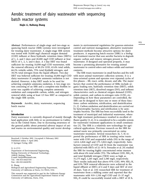
Aerobic treatment of dairy wastewater with sequencing batch reactor systemsXiujin Li,Ruihong ZhangAbstract Performances of single-stage and two-stage se-quencing batch reactor(SBR)systems were investigated for treating dairy wastewater.A single-stage SBR system was tested with10,000mg/l chemical oxygen demand (COD)influent at three hydraulic retention times(HRTs) of1,2,and3days and20,000mg/l COD influent at four HRTs of1,2,3,and4days.A1-day HRT was foundsufficient for treating10,000-mg/l COD wastewater,with the removal efficiency of80.2%COD,63.4%total solids, 66.2%volatile solids,75%total Kjeldahl nitrogen,and 38.3%total nitrogen from the liquid effluent.Two-day HRT was believed sufficient for treating20,000-mg/l COD dairy wastewater if complete ammonia oxidation is not desired.However,4-day HRT needs to be used for achieving complete ammonia oxidation.A two-stage sys-tem consisting of an SBR and a complete-mix biofilm re-actor was capable of achieving complete ammonia oxidation and comparable carbon,solids,and nitrogen removal while using at least1/3less HRT as compared to the single SBR system.Keywords Aerobic,dairy,wastewater,sequencing batch reactor1IntroductionDairy wastewater is currently disposed of mainly through land application with little or no pretreatment in Califor-nia in the United States.Due to increasing awareness of the general public about potential adverse impact of ani-mal wastes on environmental quality and recent develop-ments in environmental regulations for gaseous-emission control and nutrient management,alternative wastewater treatment methods become attractive options for dairy producers.A sequencing batch reactor(SBR)is a biolog-ical treatment reactor that uses aerobic bacteria to degrade organic carbon and remove nitrogen present in the wastewater.If designed and operated properly,it maybecome a promising alternative for treating animal wastewater to control odors and reduce solids and nutrient contents.The SBR treats wastewater in small batches andfits wellwith most animal wastewater collection systems.It is atime-oriented system and operates over repeated cycles offive phases–fill,react,settle,decant,and idle.The major factors that control the performance of SBRs include or-ganic loading rate,hydraulic retention time(HRT),solids retention time(SRT),dissolved oxygen(DO),and influent characteristics such as chemical oxygen demand(COD),solids content,and carbon-to-nitrogen ratio(C/N),etc. Depending on how these parameters are controlled,theSBR can be designed to have one or more of these func-tions:carbon oxidation,nitrification,and denitrification[1,2].Carbon oxidation and denitrification are carried outby heterotrophic bacteria and nitrification is by auto-trophic bacteria.The SBR has been successfully used in the treatment of municipal and industrial wastewater,wherethe high treatment performance resulted in excellent ef-fluent quality[3,4].It is considered to be a suitable systemfor wastewater treatment applications in small communi-ties[5].The SBR is a relatively new technology for agri-cultural applications.Previous research on the SBR foranimal waste was primarily concentrated on swine wastewater treatment.Several researchers[6,7,8]re-ported the performance of SBR in treating swine waste-water with COD and suspended solids(SS)in the range of1,614–2,826mg/l and175–3,824mg/l,respectively.Satis-factory removal of COD and SS from the wastewater was achieved with HRTs of22–30h.Fernades et al.[9]studiedthe SBR for treating highly concentrated swine manurewith about4%total solids(TS).The influent COD,NH3-N,and total Kjeldahl nitrogen(TKN)were as high as31,175mg/l,1,265mg/l,and2,580mg/l,respectively.Their results indicated that above97%COD,99%NH3-N,and93%TKN removal efficiencies were achieved in theliquid effluent at HRTs of6and9days and SRT of over20days.Tam et al.[10]researched SBR for treatment of wastewater from a milking center and reported that the wastewater with919–1,330mg/l COD and15–37mg/lNH3-N could be successfully treated with a HRT of20h. Bioprocess Biosyst Eng25(2002)103–109DOI10.1007/s00449-002-0286-9103Received:2October2001/Accepted:6February2002 Published online:5April2002ÓSpringer-Verlag2002X.Li(&)Department of Environmental Engineering,Beijing University of Chemical Technology,100029,Beijing,ChinaE-mail:lxiujin@Tel.:+86-010-********Fax:+86-010-********R.ZhangBiological and Agricultural Engineering Department, University of California at Davis,CA95616,USAThis research was supported in part by the California Energy Commission and the Agricultural Experiment Station of the University of California,Davis,USA.Studies on the SBR for treating dairy manure are not well documented in the literature.Previous researchfindings about the SBR for treatment of swine manure and other types of wastewater provide valuable references for the treatment of dairy wastewater.However,due to the dif-ferences in the characteristics of dairy wastewater from other types of wastewater,research is needed to develop design and operational guidelines for the SBR in treating dairy wastewater of various characteristics.The objectives of this study are to investigate the effects of wastewater characteristics,HRT,SRT,and organic loading rate on the performance of the SBR system in treating dairy wastewater for carbon and solids removal and nitrogen conversion,and develop design and opera-tional guidelines for the SBR system in single-and mul-tiple-stage configurations.2Materials and methods2.1Dairy manure collection and preparationDairy manure was collected on the Dairy Research Farm of the University of California at Davis.Due to runoff of urine on the feedlot,the collected manure was mainly feces and contained a relatively low content of ammonia nitro-gen.The manure was slurried with addition of water and then screened twice with two sieves with openings of4·4 and2·2mm,respectively,to remove large particles.The screened manure was transported immediately to the laboratory and stored in a freezer at–20°C until use.The TS and COD of the screened manure were30,000–40,000mg/l and35,000–50,000mg/l,respectively.When needed,the stored manure was thawed and then diluted with tap water to obtain a desired COD concentration.Due to relatively low ammonia content of the raw manure as compared to typical levels in the manure collected on dairy farms,urea was added to increase the NH3-N in the prepared manure from100–125mg/l to500–550mg/l.The prepared manure was then put into a50-l feeding tank housed in a refrigerator at4°C for daily use.The feeding tank had an agitator to mix the wastewater during the feeding of the reactors.2.2Experimental setup and operationBoth single-stage and two-stage treatment systems were tested.The single-stage SBR system consisted of an SBR and a solids-settling tank in series.The wastewater wasfirst fed into the SBR for treatment and the effluent of the SBR, including both sludge and liquid,was then discharged into a settling tank,where liquid was separated from sludge by gravity settling and characterized as liquid effluent of the system.The two-stage system consisted of an SBR(first-stage reactor),a solids-settling tank,and a complete-mix biofilm reactor(CMBR)(second-stage reactor)connected in series.The liquid effluent obtained from the solids-set-tling tank was used as influent of CMBR and further treated in the CMBR for achieving complete nitrification.The two-stage SBR-CMBR system is shown in Fig.1.Each system was fed and decanted twice a day for12h in each treatment cycle.All the peristaltic pumps used for feeding and decanting were operated automatically with a digital time controller.The time sequence for different operations during each treatment cycle of the SBR was1–3minfill,11h and4–8min react,40min settle,1–3min decant,and10min idle.The CMBR was operated as a complete-mix reactor and had long SRT provided by the attached growth on the polyethylene pellets placed in the reactor.The plastic pellets had light density(920kg/ m3)and were keptfluidized with the airflow.Each pellet was10mm in diameter and10mm in height,with a cross inside the cylinder and longitudinalfins on the outside, providing a large surface area for bacterial attachment. Thefilling volume of the pellets in total occupied ap-proximately18%of liquid volume(3l)in the reactor.The SBR and CMBR reactors were made from trans-parent acrylic and had a total volume of6l each,with51cm height and12cm diameter.During testing,the liquid vol-ume of each reactor was3l.Each reactor was aerated using pressurized air at a controlledflow rate.In order to mini-mize the water evaporation in the reactor,the air was hu-midified by traveling through water contained in a15-l jar prior to entering the reactor.The air was evenly distributed into the wastewater through four air stone diffusers in-stalled near the bottom of the reactor.All the reactors were initially seeded with the activated sludge obtained from the UC Davis Wastewater Treatment Plant and allowed to ac-climate for about2months before formal experiments were started.It normally took about4weeks for each SBR re-actor to reach a steady state when a new operating condi-tion was introduced.The steady state was defined to be a state when the weekly variations of effluent COD,TS,NH3-N,and pH were less than5%.These parameters were monitored twice a week.The CMBR had been fully accli-mated with dilute dairy wastewater for about6months and had nitrification bacteria well established before being connected with the SBR.The mixed liquor suspended solids (MLSS)in the CMBR was about10,000mg/l,which was calculated from both suspended growth and attached growth solids.In order to determine the ammonia emission from SBR due to aeration,ammonia in the exiting air of SBR was collected by absorbing it in0.3N boric acid solution for 24h under each testing condition.2.3Experimental plan and system performance evaluation The experiment was carried out in two phases.Thefirst phase was for studying the effects of influent characteris-tics,HRT,and corresponding SRT and loading rate on the performance of the single-stage SBR system.The second phase was to evaluate the performance of a two-stage SBR-CMBR system.The two systems were then compared in terms of carbon and solids removal and nitrogen conver-sion efficiencies.With the single-stage SBR system,three HRTs(1,2and 3days)were tested for wastewater of10,000mg/l COD and four HRTs(1,2,3and4days)for wastewater of20,000mg/l COD.For the wastewater of10,000mg/l COD, the corresponding loading rate and SRT for the three HRTs were10,5,and3.3g COD/l/day and8,12,andBioprocess Biosyst Eng25(2002) 10415days,respectively.For the wastewater of 20,000mg/l COD,the corresponding loading rate and SRT for the four HRTs were 20,10,6.7,and 5g COD/l/day and 1.5,3,4,and 6days,respectively.With the two-stage SBR system,2days was used first as the system HRT,with 1day for the first-stage and 1day for the second-stage for both in flu-ents,and then 2.5days was used with 2days for the first stage and 0.5days for the second stage.An air flow rate of 4l/min was applied for all runs,which was able to main-tain dissolved oxygen (DO)in the SBR and CMBR above 3mg/l.The performance of the treatment systems was evalu-ated in terms of carbon and solids removal and nitrogen conversion ef ficiencies.The parameters analyzed included TS,volatile solids (VS),COD,SCOD (soluble COD),TKN,NH 3-N,NO 2-N,and NO 3-N.Two kinds of removal/con-version ef ficiencies were used to interpret the results for carbon and solids removal and nitrogen oxidation.One ef ficiency,E t ,is based on the removal from total ef fluent (including both sludge and liquid ef fluent generated),re-flecting the removal ef ficiency through biological process alone.The other ef ficiency,E l ,was based on the removal from liquid ef fluent,i.e.,supernatant,representing the removal ef ficiency through both biological process and sludge separation.For the single-stage SBR system,the total ef fluent was the ef fluent from the SBR and the liquid ef fluent was the supernatant decanted from the solids settling tank.For the two-stage SBR-CMBR system,the total ef fluent was the combination of sludge from the settling tank and the final ef fluent from CMBR,and the liquid ef fluent was the liquid ef fluent of CMBR.Most of previous research only reports removal ef ficiency from liquid ef fluent (E l ).Actually,E l does not re flect the real capability of a system for removing various constituents from wastewater,because part of these constituents are contained in the sludge that is separated from the liquid ef fluent and discharged as a separate sludge stream.Therefore,E t needs to be used in order to assess the real capability of a system for removing various constituents from wastewater.2.4Sampling and analytical methodsAfter each reactor reached steady state under testing conditions,samples were taken from the in fluent,mixed liquor,total ef fluent,and liquid ef fluent of the reactor three times a week (every other day)for analyses of COD,SCOD,TS,VS,NH 3-N,NO 2-N,NO 3-N,and TKN.The re-moval ef ficiencies,E l and E t ,were calculated based on the data from in fluent,liquid ef fluent,and total ef fluent of the systems.The separation of sludge and liquid in the total ef fluent of the SBR was performed by settling the ef fluent in a 1-l graduated cylinder for 2h and then decanting the liquid fraction above the sludge-liquid interface line.The COD,SCOD,TS,VS,and TKN were measured according to APHA standard methods [11].The COD measured in this study was COD Cr .The pH was measured with an Accumet pH meter (Fisher Scienti fic,Pittsburgh,Pa.).The NH 3-N was measured with a gas-sensing elec-trode and the pH meter.The DO in the reactors wasmonitored on a daily basis with a DO meter (YSI Mode158,Fisher Scienti fic,Pittsburgh,Pa.).The NO 2-N was analyzed with the HACH method,using a DR/2000spectropho-tometer [12].The NO 3-N was measured with a diffusion –conductivity analyzer [13].3Results and discussion3.1Performance of the single-stage SBR system3.1.1Removal of carbon and solidsThe performance data of the SBR for 10,000mg/l COD in fluent COD of 10,000are shown in Table 1.With the increase of HRT from 1to 3days,the COD,SCOD,TS,and VS in the liquid ef fluent became lower,yielding better ef fluent quality due to increased biological conversion and improved sludge settleability,as indicated by the increased removal ef ficiencies (E l and E t ).However,there wasnoboratory setup for a two-stage SBR-CMBR system for dairy wastewater treatmentX.Li,R.Zhang:Aerobic treatment of dairy wastewater with sequencing batch reactor systems105signi ficant difference in terms of carbon and solids rem-ovals and liquid ef fluent quality for the three HRTs.For example,the increase of COD and TS removal ef ficiency E l was 5.1%and 0.3%,and E t was 5.7%and 2.0%,respec-tively,when HRT increased from 1to 3days.Therefore,1-day HRT was believed to be suf ficient for treating the dairy wastewater with 10,000mg/l COD for its satisfactory removal ef ficiency and relatively short HRT.At 1-day HRT,the removal ef ficiency from the liquid ef fluent (E l )was 80.2%for COD,63.4%for TS,and 66.2%for VS.These removals were due to both biological conversion in the SBR and sludge separation in the solids-settling tank.The removal due to biological conversion alone in the SBR,as measured by E t ,was 45.0%for COD,21.4%for TS,and 34.2%for VS.E t was signi ficantly greater than E l ,sug-gesting that the sludge separation after SBR treatment is necessary for achieving signi ficant carbon and solids re-moval from the dairy wastewater.It was found that aerobic treatment greatly enhanced the flocculation and settlea-bility of the solids in the wastewater.Good settleability of sludge was important for achieving high carbon and solids removal ef ficiency.The performance data of the SBR for 20,000mg/l COD in fluent are shown in Table 2.The 1-day HRT was tested first.It was found that it was impossible to control the SRT at a desired level due to fast solids buildup in the reactor and poor solids settleability.When the HRT was increased to 2days,there was signi ficant improvement in the ef fluent quality and increase of removal ef ficiencies.However,when the HRT was further increased to 3days,the changes in the ef fluent quality,COD,and solids removals were not signif-icant.Therefore,2-day HRT was considered enough for COD and solids removal for 20,000mg/l COD in fluent due to its relatively short retention time and high removal ef fi-ciency.At 2-day HRT,the removal ef ficiency E l of COD,SCOD,TS,and VS was 85.7%,67.1%,71.0%,and 70.6%,respectively,and E t was 35.9%,67.1%,22.8%,and 25.6%,respectively.The 4-day HRT was tested for achieving com-plete ammonia conversion.Since ammonia was not com-pletely converted at 2-day and 3-day HRT,longer HRT was needed when complete nitri fication was desired.This will be further discussed in the following nitrogen removal section.The sludge separated from the ef fluent of the SBR contained 4.1–5.9%TS.The lower in fluent COD(10,000mg/l)resulted in better sludge settleability than the higher in fluent COD (20,000mg/l).The sludge volume as the fraction of total ef fluent volume was 5–6%and 13–16%for the lower and higher levels of in fluent COD,respectively.The sludge was composed of not-degraded solids in the wastewater and newly formed bacterial cells.It can be further processed into organic soil amendment through dewatering and composting.Table 1.Ef fluent quality and treatment ef ficiencies of SBR for 10,000mg/l COD in fluentParametersIn fluent (mg/l)1-day HRT 2-day HRT3-day HRT Liquid ef fluent Total ef fluent E l (%)E t (%)Liquid ef fluent Total ef fluent E l (%)E t (%)Liquid ef fluent Total ef fluent E l (%)E t (%)(mg/l)(mg/l)(mg/l)(mg/l)(mg/l)(mg/l)COD 10,0001,9806,50080.245.01,5805,13084.248.71,4704,93085.350.7SCOD 2,9141,4571,45750.050.01,4511,45150.250.21,4281,42851.051.0TS 6,6562,4365,23263.421.42,4765,07962.823.72,4165,09863.723.4VS 5,1081,7243,36166.234.21,5323,24970.036.41,4003,16772.638.0TKN 7801953657553.218535476.354.616533878.856.7TN 78048160738.322.248059838.523.447459639.223.6NH 3-N 51012012076.576.510510579.479.4707086.386.3NO 3-N 0375545NO 2-N 024*******pH8.16.86.76.7Table 2.Ef fluent quality and treatment ef ficiencies of SBR for 20,000mg/l COD in fluentPara-meters In fluent (mg/l)1-day HRT 2-day HRT 3-day HRT 4-day HRTLiquid ef fluent Total ef fluent E l (%)E t (%)Liquid ef fluent Total ef fluent E l (%)E t (%)Liquid ef fluent Total ef fluent E l (%)E t (%)Liquid ef fluent Total ef fluent E l (%)E t (%)(mg/l)(mg/l)(mg/l)(mg/l)(mg/l)(mg/l)(mg/l)(mg/l)COD 20,0004,30013,92078.530.42,87012,82085.735.92,66012,32086.738.4167010,90091.743.3SCOD 6,6603,1973,19752.052.02,1902,19067.167.12,0052,00569.969.912151,21581.881.8TS 12,4424,36710,11564.918.73,6129,60571.022.83,4989,58071.923.033509,19573.124.3VS 10,1043,1427,92268.921.62,9727,51770.625.62,8097,33672.227.424607,05375.729.5TKN 1,14054089952.621.118063884.244.017060085.147.48550092.552.3TN 1,14057393349.718.248491857.519.548891857.219.538888863.020.5NH 3-N 54031031042.642.6828284.884.8808085.285.200100100NO 3-N 020*********NO 2-N 01314013010pH8.08.77.97.87.6Bioprocess Biosyst Eng 25(2002)1063.1.2Nitrogen conversionWith the influent of10,000mg/l COD and1-to3-day HRT,22.2–23.6%of total nitrogen(TN)was lost in the treatment process as indicated by the E t.The losses of TN for the three HRTs were not significantly different.The ammonia collection results showed that the amount of NH3-N volatilized accounted for only2–3%of TN,indi-cating that the ammonia loss through volatilization was small under these operating conditions.The rest of TN loss (approximately20%)might be due to the emission of other nitrogenous gases,such as nitrous oxides(NO and NO2)formed in the nitrification process,and nitrogen gas (N2)formed in the denitrification process.The TKN removal was53.2–56.7%from the total effluent and75–78.8%from the liquid effluent,respectively.The TKN removal mainly resulted from ammonia oxidation.With the influent of20,000mg/l COD and1-to4-day HRTs,the loss of TN was18.2–20.5%.For the1-day HRT, the ammonia collection results showed that ammonia volatilization accounted for16%of TN,indicating that most of TN loss was due to ammonia volatilization.This occurred with the low nitrification rate in the SBR.But ammonia volatilization was insignificant at2-to4-day HRTs,at which the SBR had high nitrification activities. These results might imply that ammonia volatilization could be related to nitrification activity.Little nitrification occurrence at1-day HRT was due to the short SRT of 1.5days.This agrees with thefindings of Prakasam and Loehr[14],who stated that2-day SRT was the minimum for nitrification of poultry wastes.Therefore,HRT was increased to2days and3days,and corresponding SRT were3days and4days.It was found that nitrification was able to sustain in the SBR at both HRTs.At2-day and3-day HRT,the TN and TKN removals were19.5%and44.0–47.4%from the total effluent,and57.5–57.2%and84.2–85.1%from the liquid effluent,respectively.Significant NH3-N was removed,as indicated by removal efficiency of 84.8%for2-day HRT and85.2%for3-day HRT,although there was still80–82mg/l residual NH3-N present in the effluent.It can be seen that there was no significant dif-ference between two HRTs in terms of TN,TKN,and NH3-N removal.Therefore,if complete ammonia oxidation is not required,2-day HRT would be considered efficient for treating20,000mg/l COD influent in terms of both nitrogen removal discussed here and COD and solids removal as mentioned in Sect.3.1.1.Certain amounts of residual ammonia were present in the effluent from20,000mg/l COD influent at2-day and 3-day HRT.This indicates that the nitrification process might have been inhibited in both operation conditions. Nitrification inhibition might be due to possible inhibitions of nitrification bacteria by free ammonia(FA)and free nitrous acids(FNA)and suppression of nitrification bac-teria by more competitive heterotrophic bacteria[15].NH3 was undesirable because of its odor and toxicity to aquatic lives;thus,it needed to be removed from the wastewater. Shammas[16]studied the interaction of temperature,pH, and biomass on the nitrification process and concluded that high nitrification efficiency can only be obtained with either very long detention time or a combination of highsolids concentration and elevated temperature.Therefore,HRT was further increased to4days in order to obtain complete ammonia conversion.It was found that4-dayHRT,corresponding6-day SRT,was enough for complete ammonia conversion,as indicated by zero ammonia pre-sent in the effluent(see Table2).Therefore,it could be concluded that if complete ammonia conversion is desired,4-day HRT would be needed for treating20,000mg/l COD wastewater with540mg/l NH3-N.A track study was conducted in order to further un-derstand the nitrification process in the SBR.The varia-tions of NH3-N,NO2-N,and NO3-N in the SBR during a12-h operating cycle in treating the wastewater of10,000mg/l COD at2-day HRT are shown in Fig.2.Am-monia oxidation mostly occurred in thefirst5h,as indi-cated by the increase of NO2-N and decrease of NH3-N.Since a large amount of ammonia was oxidized in the earlystage of one cycle with high nitrification,the amount of ammonia volatilization may be decreased in contrast tothe condition when nitrification is small as mentionedabove.The relationship between ammonia volatilizationand nitrification activity needs to be further investigated infuture study.The pH could be another factor related to ammonia volatilization.Since higher medium pH in-creased the gas fraction of total ammonia dissolved in the medium,ammonia volatilization could have been highwhen there was little nitrification and pH maintained rel-atively high(approximately8.0),but small when there wasgood nitrification and the pH was decreased(Fig.2).TheNO2-N increased to the peak value about5h later after feeding and then started to decrease,while NO3-N startedto increase slightly.Generally speaking,the variations ofNH3-N,NO2-N,NO3-N,and pH in the SBR during the operating cycle depends on the bioconversion dynamics inthe reactor,initial ammonia concentration,and alkalinityin the wastewater.3.2Performance of the two-stage SBR-CMBR systemAs stated above,a4-day HRT is needed for achieving complete oxidation of ammonia in the dairy wastewaterin107the single-stage SBR.It appears that increasing HRT to achieve complete nitri fication is not cost effective.This led us to explore a two-stage treatment system.Research showed that nitrifying in a separate second-stage aeration system would increase nitri fication rate,due to the more suitable environment provided by a two-stage system than a single-stage system [17].In aerobic treatment,carbon oxidation is carried out by heterotrophic bacteria,while nitri fication is carried out by autotrophic bacteria.The two groups of bacteria are signi ficantly different in physiology,substrate requirement,metabolic characteristics,and growth kinetics.In a single-stage system,both carbon oxidation and nitri fication proceed in one reactor.This forces two groups of bacteria to coexist within the same physical and chemical environment,which is not optimal for either autotrophic or heterotrophic bacteria and makes it dif ficult to achieve optimum carbon and ammonia ually,longer HRT is applied in a single-stage system to balance the slow-growing autotrophic bacteria responsible for nitri fication and fast-growing he-terotrophic bacteria for carbon oxidation.But this is not economical,as mentioned above.A two-stage system could separate carbon oxidation and the nitri fication process and make each process proceed in a separate re-actor.The first-stage reactor is intended mainly for carbon oxidation and enhancement of solids settleability,and the second-stage reactor for providing suitable conditions fornitri fication.Since carbon could be oxidized quickly by fast-growing heterotrophic bacteria,the first-stage reactorcould use a relatively shorter HRT.After the first-stage SBR treatment,the solids settleability is improved as well,the sludge generated is separated and the liquid ef fluent is used as in fluent for the second-stage reactor.Sludge sep-aration would signi ficantly increase the system removal ef ficiency and reduce concentrations of constituents such as COD,TS,and NH 3-N in the in fluent,making it possible to use a shorter HRT,while maintaining a longer SRT for nitri fication in the second-stage reactor.With the opti-mization of environmental conditions and substratecharacteristics for heterotrophic and autotrophic bacteria in separate stages as mentioned above,the overall per-formance of the two-stage system can be improved and overall HRT reduced,as indicated from the performance data presented below.The two-stage system consisted of one SBR as the first stage and one CMBR as the second stage.The CMBR was selected to be the second-stage reactor,because the at-tached bacteria growth supported by the polyethylene pellets were believed to be favorable for nitri fication bac-teria by providing a long SRT.The CMBR was used to treat the liquid ef fluent from the SBR.Both SBR and CMBR were first operated at 1-day HRT,with the system HRT being 2days for treating 10,000mg COD/l and 20,000mg COD/l in fluent,respectively.The 1-day HRT in the CMBR was determined to be the appropriate level,based on preliminary test results.The performance data of the two-stage system are shown in Tables 3and 4.It can be seen that the liquid ef fluent quality and removal ef ficiencies of carbon,solids,and nitrogen from the two-stage system at 2-day HRT were comparable to those from the single-stage SBR at 3-day HRT for both in fluents.This suggests that,based on the HRT,the two-stage system would require 1/3less reactor volume than the single-stage system and therefore appears to have more favorable economics.In addition,the two-stage system allows complete ammonia oxidation in the wastewater as indicated by zero NH 3-N present in the two-stage system ef fluent at 2-day HRT as compared to 70mg/l NH 3-N in the one-stage ef fluent at 3-day HRT.Because with the in fluent of 20,000mg/l COD ammonia volatilization was high in the first-stage SBR at 1-day HRT,Table 3.Performance of two-stage SBR-CMBR system for 10,000mg/l COD in fluent In fluent (mg/l)Stage I:SBR(1-day HRT)Stage II:CMBR (1-day HRT)E l (%)E t (%)Liquid ef fluent Liquid ef fluent (mg/l)(mg/l)COD 10,0001,9801,37486.351.1SCOD 2,9141,4571,01465.265.2TS 6,6562,4362,07668.824.8VS 5,1081,7241,47271.239.1TKN 7801956092.358.0TN 78048143544.224.7NH 3-N 510120 2.599.599.5NO 3-N 037195NO 2-N 0249180pH 8.16.87.9Table 4.Performance of the two-stage SBR-CMBR system for 20,000mg/l COD in fluentIn fluent (mg/l)stage I:SBR (1-day HRT)stage II:CMBR (1-day HRT)E l (%)E t (%)stage I:SBR (2-day HRT)stage II:CMBR (0.5-day HRT)E l (%)E t (%)Liquid ef fluent Liquid ef fluent Liquid ef fluent Liquid ef fluent (mg/l)(mg/l)(mg/l)(mg/l)COD 20,0004,3002,67686.637.028********.543.8SCOD 6,6603,1972,02069.769.7219089086.686.6TS 12,4424,3673,43272.421.83612267078.526.4VS 10,1043,1422,15278.727.029********.532.5TKN 1,14054018084.246.11804096.556.2TN 1,14057350455.823.248443062.321.5NH 3-N 540310 3.099.499.4820100100NO 3-N 020*********NO 2-N 0131341400pH 8.08.77.87.97.4Bioprocess Biosyst Eng 25(2002)108。
污水处理站英语_污水处理英语
污水处理站英语_污水处理英语污水sewage污水处理 sewage treatment一级处理 primary treatment二级处理 secondary treatment生物处理 biological treatment活性污泥法 activated sludge process曝气池 aeration tank曝气 aeration充氧oxygenation好氧消化 aerobic digestion厌氧消化 anaerobic digestion溶解氧dissolved oxygen沉淀 sedimentation搅拌agitation氯化 chlorination余氯 residual chlorine污泥 sludge泥龄sludge age回流污泥 returned sludge剩余污泥 surplus sludge消化污泥 digested sludge活性污泥 activated sludge污泥浓缩 sludge thickening污泥脱水 sludge dehydrating絮凝 flocculation水头Flood peak水头损失 head loss液面负荷 surface load、工艺参数类设计流量 Design flow泵流量pump flow栅前水深 water depth of ahead grille过栅流速Crosses the grille speed of flow 栅条间隙Grille gap过栅水头损失head loss of crosses the grille 格栅倾角Grille inclination angle过栅流量 flow of grille齿耙运行速度 rake speed有效水深Effective water depth水力停留时间HRT hydraulic residence time 水力表面负荷Hydraulic load surface污泥浓度sludge concentration污泥回流比sludge reflux ratio机械设备类粗格栅 coarse screen回转格栅除污机grille decontaminating equipment 无轴螺旋输送机shaftless screw conveyor 无轴螺旋压榨机shaftless screw compressor 潜污泵submersible sewagepump细格栅fine screen旋流沉砂器rotational sand processor砂水分离器 grit-water separator潜水搅拌器submersible agitator潜水推流器 submersible water impeller可调堰门adjustable weir曝气转刷aeration pushes吸刮泥机aspiration sludge scraper离心脱水机Decanter Centrifuge切碎机Macerator转鼓浓缩机Drum thickener絮凝剂投配单元polymer make-up & dosing unit 圆形闸门Circular gate蝶阀 butterfly valve闸阀 gate valve球阀 Ball valve止回阀 Check Valve放空阀 Emptying valve微阻缓闭止回阀 Tiny Drag Slow Shut Check Valves 电磁阀 Mgnetic valve电动阀 Mortor operated valve法兰 Flange主轴承main bearing减速机gearbox超声波流量计supersonic flow meter电磁流量计electromagnetic flow meter。
污水处理的英文文献翻译(1)
Nutrient removal in an A2O-MBR reactor with sludgereductionABSTRACTIn the present study, an advanced sewage treatment process has been developed by incorporating excess sludge reduction and phosphorous recovery in an A2O-MBR process. The A2O-MBR reactor was operated at a flux of 77 LMH over a period of 270 days. The designed flux was increased stepwise over a period of two weeks. The reactor was operated at two different MLSS range. Thermo chemical digestion of sludge was carried out at a fixed pH (11)and temperature (75℃) for 25% COD solubilisation. The released pbospborous was recovered by precipitation process and the organics was sent back to anoxic tank. The sludge digestion did not have any impact on COD and TP removal efficiency of the reactor. During the 270 days of reactor operation, the MBR maintained relatively constant transmembrane pressure. The results based on the study indicated that the proposed process configuration has potential to reduce the excess sludge production as well as it didn't detonated the treated water quality.Keywords: A2O reactor; MBR; Nutrient removal; TMP1. IntroductionExcess sludge reduction and nutrients removal are the two important problems associated with wastewater treatment plant. MBR process has been known as a process with relatively high decay rate and less sludge production due to much longer sludge age in the reactor (Wenet al., 2004). Sludge production in MBR is reduced by 28-68%, depending on the sludge age used (Xia et al.,2008). However, minimizing the sludge production by increasing sludge age is limited due to the potential adverse effect of high MLSS concentrations on membrane (Yoon et al., 2004). This problem can be solved by introducing sludge disintegration technique in MBR (Young et al., 2007). Sludge disintegration techniques have been reported to enhance the biodegradability of excess sludge (Vlyssides and Karlis, 2004). In overall, the basis for sludge reduction processes is effective combination of the methods for sludge disintegration and biodegradation of treated sludge. Advances in sludge disintegration techniques offer a few promising options including ultrasound (Guo et al., 2008), pulse power (Choi et al.,2006), ozone (Weemaes et al., 2000), thermal (Kim et al., 2003), alkaline (Li et al., 2008) acid (Kim et al., 2003) and thermo chemical(Vlyssides and Karlis, 2004). Among the various disintegration techniques, thermo chemical was reported to be simple and cost effective (Weemaes and Verstraete, 1998). In thermal-chemical hydrolysis, alkali sodium hydroxide was found to be the most effective agent in inducing cell lysis (Rocker et al., 1999). Conventionally, the nutrient removal was carried out in an A2O process. It has advantage of achieving, nutrient removal along with organic compound oxidation in a single sludge configuration using linked reactors in series (Tchobanoglous et al., 2003). The phosphoroes removal happens by subjecting phosphorous accumulating organisms (PAO) bacteria under aerobic and anaerobic conditions (Akin and Ugurlu, 2004). These operating procedures enhance predominance PAO, which are able to uptake phosphorous in excess. During the sludge pretreatment processes the bound phosphorous was solubilised and it increases the phosphorousconcentration in the effluent stream (Nishimura, 2001).So, it is necessary to remove the solubilised phosphorus before it enters into main stream. Besides, there is a growing demand for the sustainable phosphorous resources in the industrialized world. In many developed countries, researches are currently underway to recover the phosphoroes bound in the sludge's of enhanced biological phosphorus removal system (EBPR). The released phosphorous can be recovered in usable products using calcium salts precipitation method. Keeping this fact in mind, in the present study, a new advanced wastewater treatment process is developed by integrating three processes, which are: (a) thermo chemical pretreatment in MBR for excess sludge reduction (b) A2O process for biological nutrient removal (c) P recovery through calcium salt precipitation. The experimental data obtained were then used to evaluate the performance of this integrated system.2. Methods2.1. WastewaterThe synthetic domestic wastewater was used as the experimental influent. It was basically composed of a mixed carbon source, macro nutrients (N and P), an alkalinity control (NaHCO3) and a microelement solution. The composition contained (/L) 210 mg glucose, 200 mg NH4C1, 220 mg NaHCO3, 22一34 mg KH2PO4, microelement solution (0.19 mg MnCl2 4H20, 0.0018 mg ZnCl22H2O,0.022 mg CuCl22H2O, 5.6 mg MgSO47H2O, 0.88 mg FeCl36H2O,1.3 mg CaCl2·2H2O). The synthetic wastewater was prepared three times a week with concentrations of 210±1.5 mg/L chemical oxygen demand (COD), 40±1 mg/L total nitrogen (TN) and 5.5 mg/L total phosphorus (TP).2.2. A2O-MBRThe working volume of the A2O-MBR was 83.4 L. A baffle was placed inside the reactor to divide it into anaerobic (8.4 L) anoxic (25 L) and aerobic basin (50 L). The synthetic wastewater was feed into the reactor at a flow rate of 8.4 L/h (Q) using a feed pump. A liquid level sensor, planted in aerobic basin of A2O-MBR controlled the flow of influent. The HRT of anaerobic, anoxic and aerobic basins were 1, 3 and 6 h, respectively. In order to facilitate nutrient removal, the reactor was provided with two internal recycle (1R). IRl (Q= 1)connects anoxic and anaerobic and IR 2 (Q=3) was between aerobic and anoxic. Anaerobic and anoxic basins were provided with low speed mixer to keep the mixed liquid suspended solids (MLSS) in suspension. In the aerobic zone, diffusers were used to generate air bubbles for oxidation of organics and ammonia. Dissolved oxygen (DO) concentration in the aerobic basin was maintained at 3.5 mg/1 and was monitored continuously through online DO meter. The solid liquid separation happens inaerobic basin with the help of five flat sheet membranes having a pore size of 0.23 pm. The area of each membrane was 0.1 m2. They were connected together by a common tube. A peristaltic pumpwas connected in the common tube to generate suction pressure. In the common tube provision was made to accommodate pressure gauge to measure transmembrane pressure (TMP) during suction. The suction pump was operated in sequence of timing, which consists of 10 min switch on, and 2 min switch off.2.3. Thermo chemical digestion of sludgeMixed liquor from aerobic basin of MBR was withdrawn at the ratio of 1.5% of Q/day and subjected to thermo chemical digestion. Thermo chemical digestion was carried out at a fixed pH of 11(NaOH) and temperature of 75℃for 3 h. After thermo chemical digestion the supernatant and sludge were separated. The thermo-chemicallydigested sludge was amenable to further anaerobic bio-degradation (Vlyssides and Karlis, 2004), so it was sent to theanaerobic basin of the MBR2.4. Phosphorus recoveryLime was used as a precipitant to recover the phosphorous in the supernatant. After the recovery of precipitant the content was sent back to anoxic tank as a carbon source and alkalinity supelement for denitrification.2.5. Chemical analysisCOD, MLSS, TP, TN of the raw and treated wastewater were analyzed following methods detailed in (APHA, 2003). The influent and effluent ammonia concentration was measured using an ion-selective electrode (Thereto Orion, Model: 95一12). Nitrate in the sample was analyzed using cadmium reduction method (APHA, 2003).3. Results and discussionFig. 1 presents data of MLSS and yield observed during the operational period of the reactor. One of the advantages of MBR reactor was it can be operated in high MLSS concentration. The reactor was seeded with EBPR sludge from the Kiheung, sewage treatment plant, Korea. The reactor was startup with the MLSS concentration of 5700 mg/L. It starts to increase steadily with increase in period of reactor operation and reached a value of 8100 mg/L on day 38. From then onwards, MLSS concentration was maintained in the range of 7500 mg/L by withdrawing excess sludge produced and called run I. The observed yields (Yobs) for experiments without sludge digestion (run I) and with sludge digestion were calculated and given in Fig. 1. The Yobs for run I was found to be 0.12 gMLSS/g COD. It was comparatively lower than a value of 0.4 gMLSS/g CODreported for the conventional activated sludge processes (Tchoba-noglous et al., 2003). The difference in observed yield of these two systems is attributed to their working MLSS concentration. At high MLSS concentration the yield observed was found to be low (Visva-nathan et al., 2000). As a result of that MBR generated less sludge.The presently used MLSS ranges (7.5一10.5 g/L) are selected on the basis of the recommendation by Rosenberger et al. (2002). In their study, they reported that the general trend of MLSS increase on fouling in municipal applications seems to result in no impact at medium MLSS concentrations (7一12 g/L).It is evident from the data that the COD removal efficiency of A2O system remains unaffected before and after the introduction of sludge digestion practices. A test analysis showed that the differences between the period without sludge digestion (run I) and with sludge digestion (run II and III) are not statistically significant.However, it has been reported that, in wastewater treatment processes including disintegration-induced sludge degradation, the effluent water quality is slightly detonated due to the release of nondegradable substances such as soluble microbial products (Ya-sui and Shibata, 1994; Salcai et al., 1997; Yoon et al., 2004). During the study period, COD concentration in the aerobic basin of MBR was in the range of 18-38 mg/L and corresponding organic concentration in the effluent was varied from 4 to 12 mg/L. From this data it can be concluded that the membrane separation played an important role in providing the excellent and stable effluent quality.Phosphorus is the primary nutrient responsible for algal bloom and it is necessary to reduce the concentration of phosphorus in treated wastewater to prevent the algal bloom. Fortunately its growth can be inhibited at the levels of TP well below 1 mg/L (Mer-vat and Logan, 1996).Fig. 2 depicts TP removal efficiency of the A2O-MBR system during the period of study. It is clearly evident from the figure that the TP removal efficiency of A/O system was remains unaffected after the introduction of sludge reduction. In the present study, the solubilised phosphorous was recovered in the form of calcium phosphate before it enters into main stream. So, the possibility of phosphorus increase in the effluent due to sludge reduction practices has been eliminated. The influent TP concentration was in the range of 5.5 mg/L. During thefirst four weeks of operation the TP removal efficiency of the system was not efficient as the TP concentration in the effluent exceeds over 2.5 mg/L. The lower TP removal efficiency during the initial period was due to the slow growing nature of PAO organisms and other operational factors such as anaerobic condition and internal recycling. After the initial period, the TP removal efficiency in the effluent starts to increase with increase in period of operation. TP removal in A2O process is mainly through PAO organisms. These organisms are slow growing in nature and susceptible to various physicochemical factors (Carlos et al., 2008). During the study period TP removal efficiency of the system remains unaffected and was in the range of 74-82%.。
污水处理名词常用40个英语翻译汇总
污水处理名词常用40个英语翻译汇总下面是40个水处理领域内常用的名词对应的英文翻译写法,很是便利大家日后查阅英文文献时的便捷性和专业性,或许你现在用不到,但是谁知道啥时候就能用到了呢?所以水处理专业的小伙伴们赶快保藏吧!财务评价 financial evaluation配水系统 distribution system侧渠型一体化氧化沟 integrated oxidation ditch with side ditch产氢气乙酸菌 Rydrogenes and acetic aid genes产甲烷细菌 methanogenes产率系数 yield coefficient常规给水处理工艺 conventional water treatment processes放开式循环冷却水系统 opened recirculating cooling water system超高纯水 ultra-high-purify water超过滤 ultrafiltration超过滤膜法 ultrafiltration membrane process沉淀 precipitation, sedimentation沉淀池 sedimentation tank沉砂池 grit chamber城市废水 municipal wastewater城市废水处理 municipal wastewater treatment澄清 clalification可持续进展 sustainable development布满度 degree of fullness重现期 exceedion interval, period of recurrence抽风式机械通风冷却塔 induced draft mechanical cooling tower 臭氧发生器 ozone generator臭氧法 ozonation process臭氧消毒 ozone disinfection初次(级)沉淀池 primary clarifier, primary sedimentation tank除水器 drift eliminator除铁除锰 iron and manganese removal除盐水(脱盐水) desalted water,demineralized water除渣 desilication, silica removal除藻 algal removal除氟 algal fluorine穿透曲线 penetration curve活性污泥法 activated sludge process生物脱氮工艺 biological nitrogen removal process船型一体化氧化沟Boat Type in intrachannel clarifier oxidation ditch纯(富)氧曝气法 pure-oxygen aeration process磁分散 magnetic coagulation磁盘法 magnetic disk process磁过滤法 magnetic fierration process萃取 extraction萃取剂 extractant下面是40个水处理领域内常用的名词对应的英文翻译写法,很是便利大家日后查阅英文文献时的便捷性和专业性,或许你现在用不到,但是谁知道啥时候就能用到了呢?所以水处理专业的小伙伴们赶快保藏吧!财务评价 financial evaluation配水系统 distribution system侧渠型一体化氧化沟 integrated oxidation ditch with side ditch产氢气乙酸菌 Rydrogenes and acetic aid genes产甲烷细菌 methanogenes产率系数 yield coefficient常规给水处理工艺 conventional water treatment processes放开式循环冷却水系统 opened recirculating cooling water system超高纯水 ultra-high-purify water超过滤 ultrafiltration超过滤膜法 ultrafiltration membrane process沉淀 precipitation, sedimentation沉淀池 sedimentation tank沉砂池 grit chamber城市废水 municipal wastewater城市废水处理 municipal wastewater treatment澄清 clalification可持续进展 sustainable development布满度 degree of fullness重现期 exceedion interval, period of recurrence抽风式机械通风冷却塔 induced draft mechanical cooling tower 臭氧发生器 ozone generator臭氧法 ozonation process臭氧消毒 ozone disinfection初次(级)沉淀池 primary clarifier, primary sedimentation tank除水器 drift eliminator除铁除锰 iron and manganese removal除盐水(脱盐水) desalted water,demineralized water除渣 desilication, silica removal除藻 algal removal除氟 algal fluorine穿透曲线 penetration curve活性污泥法 activated sludge process生物脱氮工艺 biological nitrogen removal process船型一体化氧化沟Boat Type in intrachannel clarifier oxidation ditch纯(富)氧曝气法 pure-oxygen aeration process磁分散 magnetic coagulation磁盘法 magnetic disk process磁过滤法 magnetic fierration process萃取 extraction萃取剂 extractant。
污水处理专用术语翻译
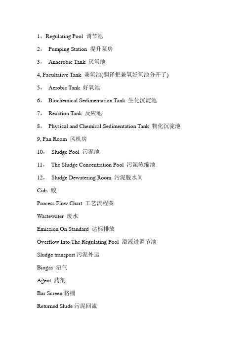
1,Regulating Pool 调节池2,Pumping Station 提升泵房3,Anaerobic Tank 厌氧池4, Facultative Tank 兼氧池(翻译把兼氧好氧池分开了)5,Aerobic Tank 好氧池6,Biochemical Sedimentation Tank 生化沉淀池7,Reaction Tank 反应池8,Physical and Chemical Sedimentation Tank 物化沉淀池9, Fan Room 风机房10,Sludge Pool 污泥池11,The Sludge Concentration Pool 污泥浓缩池12,Sludge Dewatering Room 污泥脱水间Cids 酸Process Flow Chart 工艺流程图Wastewater 废水Emission On Standard 达标排放Overflow Into The Regulating Pool 溢液进调节池Sludge transport污泥外运Biogas 沼气Agent 药剂Bar Screen格栅Returned Slude污泥回流Boiler Room 锅炉房Switching Room 配电室Add The Pharmacy 配药间Office Lab 办公化验室Legend 图例Filter Press 板框压滤机Temperature(温度)pH(pH值)BOD5 at 20°C(五日生化需氧量)Total nitrogen (as N)(总氮)COD (mg O2 /l)(化学需氧量)Total phosphorus (as P)(总磷) Suspended solids (悬浮物SS)Total ammonia (as N)(总氨氮)Oils,fats &grease (动植物油类) Phenols (酚类)Mercury (as Hg)(汞)Nickel (as Ni)(镍)Cobalt (as Co)(钴)Lead (as Pb)(铅)Antimony (as Sb)(锑)Tin (as Sn)(锡)Chromium (as Cr VI)(六价铬)Chromium (as total Cr) (总铬)Arsenic (as As)(砷)Cadmium (as Cd)(镉)Zinc (as Zn)(锌)Copper (as Cu)(铜)”Mineral oils (Interceptors)(物理处理出水矿物油)" "Benzene,toluene & xylene (combined)(苯、甲苯、二甲苯总量)”Mineral oils (Biological Treatment)(生物处理出水矿物油)””Or ganochlorine pesticides (as Cl)(有机氯农药)””Mothproofing agents (as Cl)(防蛀剂)"”Org anophosphorus pesticides (as P)(有机磷农药)”Adsorbable organic halogen compounds (AOX)(可吸附有机卤化物Sulphide(asS)(硫化物)Color (dilution ratio)(色度稀释倍数)Particulate matter(粉尘)V olatile organic carbons (as C)(excluding formaldehyde)(挥发性有机碳,不包含甲醛)Formaldehyde(甲醛)Isocyanates (as NCO)(异氰酸酯)Cyanide(氰化物)Silver总银Manganese总锰Selenium总硒Benzopyrene苯并芘Aniline苯胺类Nitrocompound总硝基化合物Malathion马拉硫磷Dimethoate乐果Parathion对硫磷Parathion—methyl甲基对硫磷Pentachlorophenol五氯酚Trichloromethane三氯甲烷Tetrachloromethane四氯甲烷Trichloro ethylene三氯乙烯Tetrachloroethylene四氯乙烯Close Xylene邻–二甲苯Face Xylene对–二甲苯Space Xylene间–二甲苯Ethylbenzene乙苯Chlorobenzene氯苯1,4—Dichlorobenzene1,4–二氯苯P-nitrchlorobenzene对硝基氯苯”2,4—Dinitrochlorobenzene2,4–二硝基氯苯”Phenol苯酚Space Cresol间–甲酚2,4—Dichlorophen2,4–二氯酚”2,4,6—Trichlorophenol2,4,6–三氯酚""Phthalic acid Dibutyl ester邻苯二甲酸二丁酯””Phthalic acid Dioctyl phthalate邻苯二甲酸二辛酯”Acrylonitrile丙烯晴给排水常用名词中英文对照1、给水工程water supply engineering 原水的取集和处理以及成品水输配的工程。
关于污水治理的高中英语语法
关于污水治理的高中英语语法
英语语法:高中英语语法-sewage treatment 污水治理
sewage treatment 污水治理
今后五年,中国投入环保领域的资金总额将到达约1.4万亿元人民币,投资将主要集中在水污染、大气环境、固体废物等领域。
请看《中国日报》相关报道:
China plans to invest 1.4 trillion yuan (US$175 billion)in environmental protection between xx and xx. At a cost of 180 billion yuan,sewage treatment facilities with a bined daily capacity of 40 million tons will be built in 10 river valleys to dispose of wastewater discharged by cities.
城市的污水处理常用sewage treatment来表达,sewage指污水。
由此,生活污水可用domestic sewage来形容,而工业污水那么是industrial sewage. Sewage做污水更侧重指下水道、排水沟排出的固体、液体废物,所以,与生活息息相关的化粪池可表示为sewage tank.
看下面一个例句:Sewage treatment methods vary.(污水处理的方法多种多样。
)。
水处理常用名词中英文对照

水处理常用名词中英文对照1、给水工程water supply engineering原水的取集和处理以及成品水输配的工程。
2、排水工程sewerage ,wastewater engineering收集、输送、处理和处置废水的工程.3、给水系统water supply system给水的取水、输水、水质处理和配水等设施以一定方式组合成的总体。
4、排水系统sewerage system排水的收集、输送、水质处理和排放等设施以一定方式组合成的总体。
5、给水水源water source给水工程所取用的原水水体。
6、原水raw water由水源地取来的原料水。
7、地表水surface water 存在于地壳表面,暴露于大气的水。
8、地下水ground water存在于地壳岩石裂缝或工壤空隙中的水。
9、苦咸水(碱性水) brackish water ,alkaline water碱度大于硬度的水,并含大量中性盐,PH值大于7。
10、淡水fresh water含盐量小于500mg/L的水。
11、冷却水cooling water用以降低被冷却对象温度的水。
12、废水wastewater居民活动过程中排出的水及径流雨水的总称.它包括生活污水、工业废水和初雨径流以及流入排水管渠的其它水。
13、污水sewage ,wastewater受一定污染的来自生活和生产的排出水.14、用水量water consumption 用水对象实际使用的水量。
-15、污水量wastewater flow ,sewage flow排水对象排入污水系统的水量。
16、用水定额water flow norm对不同的排水对象,在一定时期内制订相对合理的单位排水量的数值。
17、排水定额wastewater flow norm对不同的排水对象,在一定时期内制订相对合理的单位排水量的数值.18、水质water quality在给水排水工程中,水的物理、化学、生物学等方面的性质.19、渠道channel ,conduit天然、人工开凿、整治或砌筑的输水通道.20、泵站pumping house设置水泵机组、电气设备和管道、闸阀等的房屋。
- 1、下载文档前请自行甄别文档内容的完整性,平台不提供额外的编辑、内容补充、找答案等附加服务。
- 2、"仅部分预览"的文档,不可在线预览部分如存在完整性等问题,可反馈申请退款(可完整预览的文档不适用该条件!)。
- 3、如文档侵犯您的权益,请联系客服反馈,我们会尽快为您处理(人工客服工作时间:9:00-18:30)。
污水处理英文翻译解析河流污水处理的相关论述1 前言随着工业化和城市化的发展,水环境污染、水资源紧缺日益严重,水污染控制、水环境保护已刻不容缓。
我国现在新建城市或城区采用雨污分流制,但老城市或老城区大多仍然是雨污合流的排水体制。
许多合流污水是直接排放到水体。
而将旧合流制改为分流制,受现状条件限制大许多。
老城区建成年代较长,地下管线基本成型,地面建筑拥挤,路面狭窄,旧合流制改分流制难度较大。
合流污水的一大特点是旱季和雨季的水质、水量变化大,雨季污水 BOD 浓度低,不利于生化处理。
国家提出 2010 的我国城市污水处理率要求达到 40%, 因此研究有效的合流污水处理方法对加快城市污水处理步伐具有重要的意义。
本文针对合流污水处理的有关情况,谈一些个人看法。
2 污水处理工艺要求我国目前不少城市,新城区与老城区并存,合流制与分流制并存。
因此,新建或扩建的污水处理厂,在满足城市总体规划和排水规划需要的同时,还应能达到如下要求:1. 具备接纳旧城区合流污水的能力,具有较强的适应冲击负荷的能力。
污水处理厂污水来源包括两部分,一是新城区分流污水,二是老城区合流污水。
与合流污水相比,分流污水水质、水量变化幅度小得多,对污水处理厂调节缓冲的要求小得多。
对于合流污水,降雨前期因雨水冲刷街区,合流污水较脏,但水量相对较小,降雨后期水量较大,但污水中有机物浓度相对较小。
因此,降雨前期合流污水,可考虑与分流污水一起经预处理后进入污水处理构筑物。
降雨后期合流污水,除一部分与分流污水一起经污水预处理构筑物进入污水处理构筑物外,另一部分可考虑通过雨污溢流构筑物进入雨污溢流沉定池后排入附近水体。
为了对进入污水处理构筑物的合流污水高峰流量、水质波动进行缓冲调节,污水处理构筑物前端可设缓冲调节池以均衡水质、储存水量。
2. 具有可靠的 BOD、 COD、 SS 去除功能及氮磷去除功能,保证最终出水水质稳定。
通常情况下,城市污水中难降解有机物较少, BOD、 COD 去除比较容易实现,而氮磷去除则较复杂。
我国现行的污水排放标准对污水处理厂出水氮磷指标有严格的要求,故城市污水处理都必须达到氮磷的有效去除。
在现行城市污水脱氮除磷工艺中, A2/0 采用较为广泛。
针对 A2/0 工艺存在的问题目前出现了许多改进工艺,每种工艺又都存在各自的特点和局限。
由于合流污水引起的水质、水量波动较大,对污水厂各处理单元产生冲击,为了适应受纳水体的要求,为使 BOD、COD 等指标进一步降低,进一步去除污水中的细菌及氮、磷等植物性营养物质,在污水厂与受纳水体之间可设氧化塘。
3. 具有灵活多变的运行方式,可根据收集的污水量、进水水质以及季节变化调整运行方式。
常规 A2/0 工艺,很难做到灵活方便地调整运行方式。
但A2/0工艺从构成原理上讲,是在曝气段前加厌氧段和缺氧段。
这一原理用于氧化沟技术,便可形成各种适应不同水质、水量、季节变化的运行方式。
污水厂可根据实际情况设两个以上的氧化沟,每个沟设一定数量的水力推进器,池底均匀分布微孔爆气器。
通过调整氧化沟污水进水管阀门、曝气器的开及关的区域、内回流比大小、污泥回流比大小及水力推进器运行个数,便可形成串联、并联等若干种运行方式。
每种运行方式具有各自区域大小不同的厌氧段、缺氮段、曝气段。
当旱季污水量小则采用串联运行方式,雨季污水量大,则采用并联运行方式。
夏季温度高,硝化反应速度快,则采用具有较小曝气区域、较小硝化段的运行方式,相应反硝化区域增加、功能加强,冬季情况则正好相反。
如进水碳源浓度较低,则采取串联的、使后续反硝化段的碳源能得到补充的运行方式。
3 工艺流程选择和特点说明根据污水合流制与分流制并存的特点及处理后污水排放水体的要求: 来自新城区的分流污水,经格栅处理后进入后续污水处理构筑物; 来自老城区的合流污水平时直接进入污水处理系统。
降雨时,前期的较脏、水量较小的合流污水,与分流污水一起经格栅后进入后续污水处理构筑物。
降雨后期的合流污水水量较大主要含泥砂,一部分经雨污溢流构筑物,在沉淀池作短暂停留,去除部分泥砂后直接排放水体,另一部分则与分流污水一起经格栅后进入后续处理构筑物。
格栅用以去除污水中的大块悬浮物、漂浮物等污物,以消除大块污物对后续处理系统的不良影响。
曝气沉砂池用以去除较大砂粒及其他无机污染物颗粒,以提高污泥活性有机组分含量、减轻对管道设备的磨损、减轻后续沉淀池负荷、改善系统运行条件。
初沉池主要用以去除SS,在初沉池中,根据进水水质情况,可适时外加碳源和氨氮,以保证有足够量和适当比例的 C、 N、 P 来源,为后续生化反应正常运行创造条件。
缓冲池主要作用是在合流污水高峰流量时均衡水质、储存水量。
氧化沟是一种简易、高效、经济的城市污水处理工艺近几十年发展迅速。
在流态上,它既是完全混合式,又具有推流式特征。
由于沟渠溶解氧浓度的递减变化规律,通过适当安排进水口、出水口、回流污泥入口位置,氧化沟可形成一个倒置 A2/0 工艺。
根据硝化、反硝化、生物除磷及好氧活性污泥微生物的代谢特在缺氧段,主要功能是脱氮,回流污泥中反硝化菌以原水中有机物为碳源,以来自好氧段的硝化液中的硝酸盐为电子受体,将硝态氮 NO-3-N 还原为气态氮 N2。
在厌氧段,主要功能是释磷,回流污泥中聚磷菌分解释放体内聚磷酸盐,同时摄入污水中的有机物,以 PHB 及糖原等形式储存于细胞内。
对于缺氧段与厌氧段的过渡过区域,既非严格的厌氧状态,而溶解氧浓度又低于缺氧段,脱氮与释磷过程都将存在,但都不易取得竞争优势。
在好氧段,功能有三: 1、好氧活性污泥中微生物,使污水中有机物得到降解、去除,好氧微生物本身得以增殖,活性污泥得以增长;2、在亚硝化菌和硝化菌作用下,将污水中氨氮 NH+4-N 氧化成硝态氮,主要为NO-3-N; 3、聚磷菌体内 PHB 氧化产生大量能量一部分用于从污水中过量吸收磷酸盐,并以聚磷的形式贮存于体内,一部分供给细菌合成和维持生命。
与 A2/0工艺相比,前置缺氧段不仅可优先从污水中获得碳源,强化反硝化过程。
同时,因先经历反硝化过程,消除了硝酸盐的大量存在对聚磷菌厌氧释磷过程的不利影响。
通过对曝气器的控制,沟渠内可形成区域大小适宜的缺氧段、厌氧段、曝气段,在去除BOD 的同时进行生物脱氮除磷,能取得较好的氮磷去除效果。
特别是能够通过对曝气区域大小和进出水管阀门的控制,形成灵活多变的运行方式,适应污水水量、水质、季节性的变化,具有广阔的发展应用前景。
当水质波动幅度不大时,通过前述的预处理、生物处理后的污水,一般能排放水体,但由于各种不确定偶发因素的影响,这样考虑处理水排放存在不小风险。
当水质、水量大幅波动时这种情况更为突出。
由于水污染、生态破坏的严峻形势,城市污水处理厂必须从技术上严格把关,从工艺上确保处理水安全排放水体。
若在生物处理工艺之后设置熟化塘,不仅可在污水处理厂和受纳水体之间起缓冲作用,还能通过藻类-动物性浮游生物-鱼类等食物链和生态系统,使 BOD、 COD指标、细菌及氮磷等植物性营养物浓度进一步降低,具有良好稳定的处理效果。
特别是在熟化塘系统中,通过塘内生态系中多条食物链的物质迁移、转化和能量逐级传递、转化,在去除污染的同时,以水产资源形式达到物质、能量的回收,将污水处理与利用相结合,实现污水资源化。
4 结语1. 合流制污水水质、水量波动幅度大, 技术工艺必须满足缓和冲击负荷的要求,设置缓冲池均衡水质、储存水量比较适宜。
2. 通过多个氧化沟构成若干个串、并联运行方式,在适应进水水质、水量、季节性变化方面能够发挥重要作用。
3. 通过安排适当的进出水口位置、回流污泥入口位置,氧化沟可形式一个倒置A2/0 工艺,在去除 BOD 的同时,能取得较好的氮磷去除效果4. 熟化塘的应用,为处理水安全排放水体,能够提供可靠的技术保证。
熟化塘投资省、运行费用低、管理维护方面、污水处理与利用相结合,在防治水污染、保护水环境及生态环境综合治理方面具有明显优势。
如果美化熟化塘表观,设置喷泉等设施,形成供人们休闲、游乐的人工景点,协调城市建设中土地资源的合理配置,那么熟化塘占地面积较大这一不足就不会成为突出的问题。
Combined sewage treatment related discussion1 PrefaceWith the industrialization and urbanization development, water pollution, worsening water shortage, water pollution control, environmental protection has urgent need of water. China is now adopting a new city or urban stormwater sewage diversion system, but the old city or the old city is still mostly combined sewage stormwater drainage system, a number of combined sewage is directly discharged into the water body. The confluence of the old system to a triage system, the status quo conditions, and many of the old city built during the long, underground pipeline basic shape, the ground construction crowded,narrow roads, the old Combined triage system more difficult to change. Combined sewage is a major feature of the water quality of the dry and wet seasons, water changes, low BOD effluent concentration during the rainy season is not conducive to biochemical treatment. Countries, 2010 China's urban sewage treatment rate of 40 percent required, and therefore the study of the convergence of effective methods of sewage treatment, sewage treatment to accelerate the pace of the city is of great significance. In this paper, the convergence of the sewage treatment situation, some personal views.2 Requirements of the sewage treatment processMany cities in China, the new city with the coexistence of the old city, Combined with the streaming system co-exist. Therefore, new or expanded sewage treatment plant to meet the overall urban planning and drainage planning requirements should be able to meet the following requirements:(1) Have to accept merging the old city sewage capabilities, astrong ability to adapt to the impact load. Source of the sewage treatment plant effluent is composed of two parts: First, the new urban sewage diversion; Second, merging the old city sewage. Compared with the combinedsewage, sewage diversion of water quality, water, a much smaller range of sewage treatment plants require much less adjustment buffer. The confluence of sewage and rain red rain due to pre-rinse blocks, merging more dirty water, but water is relatively small; rain water, thelarger the latter, but the concentration of organic compounds in water is relatively small. Therefore, pre-confluence rain water,could be considered together with the diversion of sewage by pre-treated sewage into the structure. Combined sewage late rainfall, with the exception of part of the sewage, together with the diversion of sewage by pre-treatment structures into the sewage treatment structures, and the other part to consider the adoption of stormwater pollution entering the storm sewage overflow structures Shen overflow pool set into the nearby water body after. In order to enter the structure of the combined sewage effluent peak flow, water quality buffer fluctuations conditioning, sewage treatment structures regulating the front-end buffer pool can be installed in order to balance water quality, storage of water.(2) Reliable BOD, COD, SS removal of nitrogen and phosphorus removal function and features to ensure the stability of the final effluent quality. Under normal circumstances, urban sewage in less refractory organic matter, BOD, COD removal is easier to achieve, rather than the complexity of nitrogen and phosphorus removal. The current effluent standards for sewage treatment plant effluent nitrogen and phosphorus indicators have strict requirements, it must be of urban sewage treatment to achieve the effective removal of nitrogen and phosphorus. Under the existing urban sewage nitrogen and phosphorus removal process, A2 / 0 used more widely. For the A2 / 0 process problems, the present situation of a number of improvements in technology, technology also exists for each of the characteristics and limitations of each. As aresult of merging the water quality caused by sewage, water, volatile, wastewater treatment plant on the impact of the processing units, in order to adapt to the receiving water requirements, in order to BOD, COD and other indicators of a further drop low, further removal of sewage bacteria and nitrogen, phosphorus and other plant nutrients in the wastewater treatment plant and receiving water can be established between the oxidation pond.(3) With flexible operation mode, according to the quantity ofsewage collection, water quality and seasonal variation of the adjustment operation. Conventional A2 / 0 process, it is difficult to do adjust the flexible operation mode. However, A2 / 0 process from the principle constitutes a sense, before the paragraph in the aeration and anoxic plus anaerobic paragraph. This principle for the oxidation ditch technology can be adapted to the formation of a variety of different water quality, quantity, seasonal changes in the operating mode. Wastewater treatment plant can be established according to the actual situation of the oxidation ditch more than two, each for a certain amount of ditch water propeller,bottom uniform microporous gas explosion device.3 Selection and characteristics of that processOxidation ditch is a simple, efficient and economical municipal wastewater treatment technology, has developed rapidly in recent decades. In the flow pattern, it is completely mixed, but also has push-flow characteristics. As a result of the decreasing concentration ofdissolved oxygen ditches changes and appropriate arrangements through the inlet, outlet, back to the entrance of the location of the sludge, oxidation ditch can be inverted to form a A2 / 0 process: Combined sewage system in accordance with the characteristics ofboth a triage system, and treated water discharge requirements.Grille to remove the effluent suspended solids in the large,floating debris such as dirt, to remove large pieces of dirt on the follow-up to the adverse effects of treatment systems. Aerated grit chamber to remove large sand particles and other inorganic pollutants in order to improve Active organic component content in the sludge, reducing wear and tear on the plumbing, the follow-up sedimentation tanks to reduce load and improve the system operating conditions. Primary sedimentation tank for removal of the main SS, Shen pool in the beginning, according to the influent water quality can be a timely addition to carbon and nitrogen in order to ensure adequate and proper proportion of C, N, P sources, in order to follow-up biological and chemical response to create theconditions for normal operation. The main role of a buffer pool of sewage in the combined balance of the water quality peak flow, storage of water.And A2 / 0 process, the pre-hypoxic paragraph priority not only to obtain carbon from the wastewater, and strengthen the process of denitrification. At the same time, by first going through the process ofdenitrification, nitrate eliminated the existence of a large number of PAOs anaerobic phosphorus release the adverse effects of the process.City of diversion from new sewage treatment by the grating into the sewage treatment follow-up structures; from the merging of the old city sewage, usually directly into the sewage treatment system. Rainfall, the pre-than dirt, water, the merging of smaller sewage, together with the diversion of sewage into the follow-up by the grating structures sewage treatment; the merging of the late rains the sewage water, largely with silt, some through stormwater pollution overflow structures, in the sedimentation tank for a short stay, after the removal of some sediment, direct discharge of water bodies, the other part, together with the diversion of sewage into the follow-up by the grating structures to deal with.In accordance with nitrification, denitrification, biological phosphorus removal activated sludge and aerobic metabolism of microorganisms in the anoxic paragraph, the main function is to denitrification, sludge return to denitrifying bacteria as a carbon source oforganic matter in raw water, from the aerobic paragraphnitrification of nitrate solution for the electron acceptor, the nitrate (NO-3-N) back into gaseous nitrogen (N2). Anaerobic paragraph, the main function is to address the phosphorus, the return sludge in the decomposition of phosphate accumulating bacteria in vivo release of polyphosphate, while intake of organic matter in wastewater to the formof PHB and glycogen stored in the cells. Hypoxic anaerobic paragraph for paragraph and the transition over the region, neither strictly anaerobic state,And the concentration of dissolved oxygen above and below the anoxic, denitrification and phosphorus release process will exist, but are not easy to gain a competitive edge. In aerobic, functions There are three: first, Aerobic activated sludge micro-organisms, so that has been the degradation of organic matter in wastewater, removed themselves to the proliferation of aerobic micro-organisms, activated sludge to growth; Second, Nitrosation nitrification bacteria and fungi Under the effect of ammonia nitrogen in the wastewater (NH +4- N) oxidized to nitrate (mainly NO-3-N); III PAOs PHB in vivo oxidation of a large amount of energy, part of the sewage from excessive absorption of phosphorus salts, and the form of poly-P stored in the body, part of the supply and maintenance of bacterial synthesis4 ConclusionBy Aerator control ditches can be suitable for the formation of the size of the hypoxic region paragraph, paragraph anaerobic, aeration paragraph, at the same time in the BOD removal of biological nitrogenand phosphorus removal to obtain a better removal of nitrogen and phosphorus effect. In particular to Aeration through the pipes into and out of the region and the size of the control valve to form a flexible operation mode, to adapt to water, sewage, water quality, seasonal changes, there are broad prospects for development of applications.古今名言敏而好学,不耻下问——孔子业精于勤,荒于嬉;行成于思,毁于随——韩愈兴于《诗》,立于礼,成于乐——孔子己所不欲,勿施于人——孔子读书破万卷,下笔如有神——杜甫读书有三到,谓心到,眼到,口到——朱熹立身以立学为先,立学以读书为本——欧阳修读万卷书,行万里路——刘彝黑发不知勤学早,白首方悔读书迟——颜真卿书卷多情似故人,晨昏忧乐每相亲——于谦书犹药也,善读之可以医愚——刘向莫等闲,白了少年头,空悲切——岳飞发奋识遍天下字,立志读尽人间书——苏轼鸟欲高飞先振翅,人求上进先读书——李苦禅立志宜思真品格,读书须尽苦功夫——阮元非淡泊无以明志,非宁静无以致远——诸葛亮熟读唐诗三百首,不会作诗也会吟——孙洙《唐诗三百首序》书到用时方恨少,事非经过不知难——陆游问渠那得清如许,为有源头活水来——朱熹旧书不厌百回读,熟读精思子自知——苏轼书痴者文必工,艺痴者技必良——蒲松龄声明访问者可将本资料提供的内容用于个人学习、研究或欣赏,以及其他非商业性或非盈利性用途,但同时应遵守著作权法及其他相关法律的规定,不得侵犯本文档及相关权利人的合法权利。