三轴点胶机说明书模板
QZ-NC0903点胶机说明书

QZ-NC0903(手持版)说明书三轴智能点胶机控制系统目录1.产品介绍 (3)产品概述 (3)功能简介 (3)功能特性 (3)产品列表 (4)2.接线说明图 (5)控制器接线引脚定义 (5)控制器接线说明....... . (6)系统连接示意图 (7)转接板接线说明 (8)转接板接线示意图............................................................................................ . (9)安装尺寸.......................................................................................................... (10)3.按键说明 (11)手持盒按键图 (11)手持盒按键说明 (11)4.手持盒操作说明 (13)开机画面介绍 (13)主菜单功能介绍 (15)新增功能操作 (19)插入指令操作 (28)删除指令操作 (28)复制指令操作 (28)阵列复制操作 (29)偏移操作 (29)批量修改 (30)自动圆角 (30)类型批量修改 (30)系统 (31)执行方式操作 (33)复位方式操作 (33)产量设定 (34)默认参数 (34)拉丝工艺 (35)停机位置 (35)空移速度 (36)定滴功能 (36)对针操作 (36)M A R K点对针操作 (36)拨码开关说明 (37)5.注意事项 (37)装机事项 (37)常见问题说明与故障排除 (37)1.产品介绍产品概述QZ-NC0903是由本公司专业数控团队为点胶机行业量身定做的低成本、高浓缩、高集成度的智能点胶机控制系统。
功能简介1、手持盒采用320*240高分辨率彩屏、全中文操作界面,易学易用。
2、具有画点、直线、多段线、三维圆弧(空间圆弧)、圆、跑道、矩形、涂布、自动圆角、不规则三维样条曲线等图形元素;丰富的手工教导功能及图形预览功能。
三轴点胶机控制器-手持版操作说明书 V6.0

三轴点胶机控制系统OYT – 450GJM(手持盒版)OYT- 450GJM是由欧雅拓专业数控团队专为点胶行业量身定做的低成本、高浓缩、高集成度的智能点胶机控制系统;适用于所有通讯类电子产品点胶加工如手机、平板、显示器;小型医疗器械如血压仪;汽车产品如导航仪、车载记录仪;智能穿戴设备如手环、照相机等任何需要点胶加工的电子产品。
1、具有画点、直线、多段线、三维圆弧(空间圆弧)、圆、跑道、距形、涂布、自动圆角、不规则三维样条曲线等图形元素;丰富的手工教导功能及图形预览功能。
2、支持PLT格式文件导入,实现直接导入文件的路径数据,省去繁锁的手工教导,方便准确。
对于广告行业的图形LOGO 和文字涂胶非常方便。
3、具有区域阵列复制,平移运算,批量编辑,单步运行,I/O输入输出等功能。
4、系统具有自动执行功能、自动复位、产量设定、加工时间计时器等功能。
5、具有四种不同的拉丝工艺选择,可解决拉丝等工艺难题。
6、动作参数编辑完毕,通过串口将动作参数下载到控制器中,即可脱机独立运行。
也可将动作参数保存到手持盒的SD卡中,方便调用;并能进行设备间的图形拷贝及保存。
7、手持盒配备2G的SD卡,可存储数千个加工文件,每个文件可支持8000条指令,使用时调出即可。
8、硬件上具备4个枪通道控制、4路通用输出、8路输入、12路高速脉冲输出;控制点胶时间精度1ms。
9、每条动作指令都有独立的开胶延时、关胶延时、退枪高度、独立的提前关胶功能,灵活的批量修改功能可以提高编辑效率,也可解决堆胶问题。
10显示方式320*240 2.8寸高分辨率彩屏、全中文操作界面,易学易用工作电压210~220V AC 350W 加工范围300/400/500 mm脉冲频率100K 接口方式DB44接口工作温度5~70℃工作湿度20%-90%最大负重5~10kg 移动速度XY0.1~800/Z350/s重复精度+/-0.01mm/Axis 传动方式PMI精密导轨同步带。
三轴点胶机说明书(完整资料).doc
【最新整理,下载后即可编辑】目录第一章概述 (4)1.1 硬件 (4)1.2 软件 (5)1.3 配件 .......................................................................... 错误!未定义书签。
1.4 主板尺寸(单位:mm)................................... 错误!未定义书签。
1.5 手持编程器尺寸(单位:mm)..................... 错误!未定义书签。
第二章主界面及按键说明 (6)2.1 主界面说明 (6)2.2 手持编程器按键说明 (8)2.3 程序选择及对针按键说明................................. 错误!未定义书签。
第三章编程的基本方法说明 .. (11)3.1 单位符号解释 (11)3.2 点胶程序结束的约定 (12)3.3 点胶程序运行方式 (12)3.4 点胶的基本路径组成 (12)第四章菜单1 (15)4.1 第1页1.文件名编辑 (16)4.2 第1页2.生成默认点胶参数 (16)4.3 第1页3.编辑多个编程点 (17)4.4 第1页4.设置标号 (21)4.5 第1页5.阵列点胶 (21)4.6 第1页6.阵列展开操作 (22)4.7 第1页7.调用子程序 (22)4.8 第1页8.调用文件 (23)4.9 第1页9.程序跳转 (23)4.10 第2页1.有限次数循环 (24)4.11 第2页2.程序结束或返回 (24)4.12 第2页3.延时 (24)4.13 第2页4.暂停 (25)4.14 第2页5.输入信号编程 (25)4.15 第2页6.输出信号编程 (25)4.16 第2页7.方形涂胶 (25)4.17 第2页8.圆形涂胶 (26)4.18 第2页9.点胶信号开/关 (26)4.19 第3页1.工件计数器 (26)4.20 第3页2.回空闲停留位置 (26)4.21 第3页3.回原点 (27)第五章菜单2 (27)5.1 第1页1.对针点设置 (27)5.2 第1页2.校准对针点 (27)5.3 第1页3.胶枪下移限制值设置 (28)5.4 第1页4.空闲停留点坐标设置 (28)5.5 第1页5.胶枪提起高度设置 (28)5.6 第1页6.空移速度设置 (28)5.7 第1页7.提前出胶时间设置 (29)5.8 第1页8.线段点胶速度设置 (29)5.9 第1页9.线段点胶拉丝参数设置 (29)5.10 第2页1.线段点胶时间参数设置 (30)5.11 第2页2.单点点胶参数设置 (31)5.12 第2页3.急停时输出信号设置 (31)5.13 第2页4.输出信号初始化设置 (31)5.14 第2页5.空闲滴胶时间设置 (31)5.15 第2页6.匀速调试速度设置 (32)5.16 第2页7.工件计数器设置 (32)第六章菜单3 (32)6.1 第1页1.针头移动到指定坐标 (32)6.2 第1页2.文件复制 (33)6.3 第1页3.DXF文件转换 (34)6.4 第1页4.对当前文件锁定/解锁 (34)6.5 第1页5.对机器高级锁定/解锁 (34)6.6 第1页6.当前文件锁定密码设置 (34)6.7 第1页7.机器高级锁定密码设置 (34)6.8 第1页8.输入口名称编程 (34)6.9 第1页9.输出口名称编程 (35)6.10 第2页1.按键声音设置 (35)6.11 第2页2.速度优先等级设置 (35)6.12 第2页3.小键盘锁定/解锁 ............................ 错误!未定义书签。
三轴点胶机控制系统-锦宏科技

默 认(坐 标 微 调 键 盘 输 入)
第 6 页 共 37 页
彭先生
东莞锦宏科技有限公司
手机 15992921570
2.3 系统连接示意图
系统接线头示意图
30 43 8
电源+24 V 电源 GND
第 2 页 共 37 页
彭先生
东莞锦宏科技有限公司
手机 15992921570
1.产品介绍
1.1 产品概述
公司专业数控团队为点胶机行业量身定做的低成本、 高浓缩、 高集成度的智能点胶 机控制系统。
1.2 功能简介
1、手持盒采用 320*240 高分辨率彩屏、全中文操作界面,易学易用。 2、具有画点、直线、多段线、三维圆弧(空间圆弧)、圆、跑道、距形、涂布、自动圆角、不规则三维样条 曲线等图形元素;丰富的手工教导功能及图形预览功能。 3、具有条件跳转功能,和双 MARK 点旋转对针功能。 4、具有断点执行功能,可以从指定点开始执行。 5、具有区域阵列复制,偏移操作,批量编辑,单步运行,I/O 输入输出等功能。 6、具有自动执行、自动复位、产量设定、加工时间计时器等功能。 7、具有四种不同的拉丝工艺选择,可解决拉丝等工艺难题。 8、支持 DXF 和 PLT 文件导入,自动路径优化功能。 9、动作参数编辑完毕,通过串口将动作参数下载至控制器中,即可脱机独立运行。也可将动作参数保存 到手持盒的 SD 卡中,方便调用;并能进行设备间的图形拷贝及保存。 10、手持盒配备 2G 的 SD 卡,可存储数千个加工文件,每个文件可支持 8000 条指令,使用时调出即可。 11、硬件上具备 4 个枪通道控制、4 路通用输出、8 路输入、12 路高速脉冲输出;控制点胶时间精度 1ms。 12、每条动作指令都有独立的开胶延时、关胶延时、退枪高度、独立的提前关胶功能,灵活的批量修改功 能可以提高编辑效率,也可解决堆胶问题。 13、支持按类型分类批量修改参数。
点胶机使用说明

一、点胶机手持编程器说1.4 坐标轴控制区二、各程序代码所示含义:在手持编程器的功能键区(如图1.3所示),存在5个键,各个键所代表的含义为:MODE:模式转换键CH:选择频道键OBJ:命令选择键EDIT:编辑键AUX:辅助参数设置键三、编程过程:1、选择工作模式:自动点胶机操作使用说明需要编写程序时,首先打开点胶机的电源,然后利用点胶机手持编程器进行1.1 手持编程器 1.2 手持编程器按键控制区 在手持编程器的功能键区,利用MODE键进行模式的转换,每次按下MODE后,就会使现在的模式状态进行转变,转变为下一个模式。
在按下MODE键不同次数时,在编程屏幕显示区可以得到下面图片所示的几个功能模式:1.3 功能键区编程屏幕显示区2、选择所需编写的新程序的存储位置(即频道的选择):当我们想要进行新的程序编写的时候,我们应该连续按下手持编程器的功能按键区的“MODE”键,使手持编程器的编程屏幕显示区出现如图3.4的界面。
此时,机器处于编程模式,再按下手持编程器功能按键区的“CH”键,将会出现如下图3.5所示的界面:图3.4所示的工作模式,在此工作模式下,可以将点胶动作通过手持编程器进行写入,所以,当我们开始一个新的程序编写的时候,应该连续按下功能键MODE,使编程屏幕显示区内显示如图3.4所示界面,在此界面下继续进行下一步。
3.1 测试模式:此模式下,编辑好的程序通过手持编程器上的按键可以单步运行。
3.2 自动模式:此模式下,编辑好的程序通过手持编程器按键可自动运行3.3 外部模式:此模式下,即可通过外部按键和手持控制器上的按键进行操作。
3.4 编程模式:在此模式下,可以将点胶动作通过手持编程器进行写入程序。
3、程序的编辑:在命令选择键“OBJ”目录下各命令的含义如下:3.5 编程模式界面按下CH键后出现的界面 3.6 利用手持编程器数字键键入55后 在图3.5所示界面下,我们可以输入要编写的新程序的存储地址即程序存储的频道。
三轴点胶机说明指导书

三轴点胶机说明指导书目录第一章概述 (4)硬件 (4)软件 (6)配件.................................................... 错误!未定义书签。
主板尺寸(单位:mm) .................................... 错误!未定义书签。
手持编程器尺寸(单位:mm)............................... 错误!未定义书签。
第二章主界面及按键说明 (7)主界面说明 (7)手持编程器按键说明 (9)程序选择及对针按键说明 .................................. 错误!未定义书签。
第三章编程的基本方法说明. (13)单位符号解释 (13)点胶程序结束的约定 (14)点胶程序运行方式 (14)点胶的基本路径组成 (15)第四章菜单1 (18) (18) (18) (19) (23) (23) (25) (25) (26) (26) (27) (27) (28) (28) (29) (29) (29) (30) (30) (30) (30)第五章菜单2 (31) (31) (31) (32) (32) (32) (33) (33) (34) (34) (35) (35) (36) (36) (36) (36) (37)第六章菜单3 (37) (37) (38) (39) (39) (40) (40) (40) (40) (40) (40)........................................................ 错误!未定义书签。
........................................................ 错误!未定义书签。
第一章概述概述……ARM,DSP,FPGA,彩屏1.1硬件2.电机轴输出:5轴输出,分别为XYZ三维坐标轴,A轴旋转轴,实现双Y轴功能的Y2扩展轴,可实现带旋转轴的双Y轴点胶机台控制。
三轴自动点胶说明书
10)常用图形 ............................................................................................. 4-6
4.1.11
11)类型查找 ............................................................................................. 4-9
4.1.12
12)局部调整 ........................................................................................... 4-10
4.1.13
13)多重阵列 ........................................................................................... 4-10
2.8 第八步:选择/新建加工文件 ...................................................................................................... 2-11
2.9 第九步:设置文件参数 ................................................................................................................ 2-13
2 第二章 操作指南 .......................................................................................................................................... 2-2
三轴点胶机控制器(差分)~手持版使用说明书V8.2
三轴智能点胶机控制系统QZ-NC03(手持版)V8.2说明书东莞全职数控科技有限公司目录1.产品介绍 (3)1.1产品概述 (3)1.2功能简介 (3)1.3功能特性 (3)1.4产品列表 (4)2.接线说明图 (5)2.1 系统连接示意图 (5)2.2 安装尺寸.......................................................................................................... (6)3.按键说明 (7)3.1手持盒按键图 (7)3.2手持盒按键说明 (8)4.手持盒操作说明 (9)4.1开机画面介绍 (9)4.2主菜单功能介绍 (12)4.3新增功能操作 (15)4.4插入指令操作 (24)4.5删除指令操作 (24)4.6复制指令操作 (24)4.7阵列复制操作 (25)4.8偏移操作 (25)4.9批量修改 (26)4.10自动圆角 (26)4.11类型批量修改 (26)4.12系统 (26)4.13执行方式操作 (28)4.14复位方式操作 (29)4.15产量设定 (29)4.16默认参数 (30)4.17拉丝工艺 (30)4.18停机位置 (31)4.19空移速度 (31)4.20定滴功能 (32)4.21对针操作 (32)4.22 MARK点对针操作 (32)5.注意事项 (33)5.1装机事项 (33)5.2常见问题说明与故障排除 (33)1.产品介绍1.1产品概述QZ-NC03是由本公司专业数控团队为点胶机行业量身定做的低成本、高浓缩、高集成度的智能点胶机控制系统。
1.2功能简介1、手持盒采用320*240高分辨率彩屏、全中文操作界面,易学易用。
2、具有画点、直线、多段线、三维圆弧(空间圆弧)、圆、跑道、矩形、涂布、自动圆角、不规则三维样条曲线等图形元素;丰富的手工教导功能及图形预览功能。
三轴点胶机说明书模板
目录第一章概述 (3)1.1硬件 (3)1.2 软件 (4)1.3 配件.................................................. 错误!未定义书签。
1.4 主板尺寸(单位:mm).................................. 错误!未定义书签。
1.5 手持编程器尺寸(单位:mm)............................ 错误!未定义书签。
第二章主界面及按键说明.. (5)2.1 主界面说明 (5)2.2 手持编程器按键说明 (6)2.3 程序选择及对针按键说明................................ 错误!未定义书签。
第三章编程的基本方法说明 (9)3.1 单位符号解释 (9)3.2 点胶程序结束的约定 (9)3.3 点胶程序运行方式 (9)3.4 点胶的基本路径组成 (10)第四章菜单1 (12)4.1 第1页1.文件名编辑 (12)4.2 第1页2.生成默认点胶参数 (12)4.3 第1页3.编辑多个编程点 (13)4.4 第1页4.设置标号 (16)4.5 第1页5.阵列点胶 (17)4.6 第1页6.阵列展开操作 (18)4.7 第1页7.调用子程序 (18)4.8 第1页8.调用文件 (19)4.9 第1页9.程序跳转 (19)4.10 第2页1.有限次数循环 (19)4.11 第2页2.程序结束或返回 (20)4.12 第2页3.延时 (20)4.13 第2页4.暂停 (20)4.14 第2页5.输入信号编程 (20)4.15 第2页6.输出信号编程 (21)4.16 第2页7.方形涂胶 (21)4.17 第2页8.圆形涂胶 (21)4.18 第2页9.点胶信号开/关 (22)4.19 第3页1.工件计数器 (22)4.20 第3页2.回空闲停留位置 (22)4.21 第3页3.回原点 (22)第五章菜单2 (22)5.1 第1页1.对针点设置 (22)5.2 第1页2.校准对针点 (22)5.3 第1页3.胶枪下移限制值设置 (23)5.4 第1页4.空闲停留点坐标设置 (23)5.5 第1页5.胶枪提起高度设置 (23)5.6 第1页6.空移速度设置 (23)5.7 第1页7.提前出胶时间设置 (23)5.8 第1页8.线段点胶速度设置 (24)5.9 第1页9.线段点胶拉丝参数设置 (24)5.10 第2页1.线段点胶时间参数设置 (24)5.11 第2页2.单点点胶参数设置 (25)5.12 第2页3.急停时输出信号设置 (25)5.13 第2页4.输出信号初始化设置 (25)5.14 第2页5.空闲滴胶时间设置 (25)5.15 第2页6.匀速调试速度设置 (25)5.16 第2页7.工件计数器设置 (25)第六章菜单3 (26)6.1 第1页1.针头移动到指定坐标 (26)6.2 第1页2.文件复制 (26)6.3 第1页3.DXF文件转换 (27)6.4 第1页4.对当前文件锁定/解锁 (27)6.5 第1页5.对机器高级锁定/解锁 (27)6.6 第1页6.当前文件锁定密码设置 (27)6.7 第1页7.机器高级锁定密码设置 (27)6.8 第1页8.输入口名称编程 (27)6.9 第1页9.输出口名称编程 (28)6.10 第2页1.按键声音设置 (28)6.11 第2页2.速度优先等级设置 (28)6.12 第2页3.小键盘锁定/解锁............................. 错误!未定义书签。
三轴点胶机说明书

三轴点胶机说明书第一章概述概述……ARM,DSP,FPGA,彩屏1.1硬件2.电机轴输出:5轴输出,分别为XYZ三维坐标轴,A轴旋转轴,实现双Y轴功能的Y2扩展轴,可实现带旋转轴的双Y轴点胶机台控制。
3.加减速特性:S型曲线加减速模式,加减速加速度独立设置;10K的速度刷新频率,让机械响应性能更好,噪音更小。
4.脉冲输出频率:4MHz的直线插补,2MHz的圆弧插补(包括三轴空间圆弧插补),以电机每转20000个脉冲为例,可达到 6000转/分,足以满足现有的高速伺服电机 5000转/分的要求。
5.原点、限位输入:每个电机轴带独立专用的原点输入、正负限位输入,无需占用可编程通用输入的硬件资源。
6.可编程输入输出:各12路独立专用的可编程输入输出,均采用光耦隔离,每路输出电流最大可达500mA。
7.支持3位拨码盘或3位数码管接口,两种方式任选(菜单设置),可快速选择切换0-999的1000个点胶文件。
8.对针用小键盘,在无手持编程器时也可以方便实现因换针头引起的误差进行校正。
9.功能键:有‘运行/暂停’、‘停止’、‘回原点’、‘出胶测试’、‘单步测试’五个功能按键,并有相应的指示灯控制输出;具有‘紧急停止’按钮输入。
10.具有CAN总线、RS-232、网口,可给有特殊需要的客户定制专用程序。
11.U盘读写功能:使用FAT32文件系统,不再受大于2G容量的U盘无法格式化成FAT格式的限制。
12.存储空间:主板256MB,可存储1000个点胶文件,每个文件4000个编程点;手持编程器16MB,可存储开机画面,点胶文件,在多台机器互相拷贝点胶文件尤其有用。
13.手持编程器屏幕:采用480 X 272像素、1600万色真彩色4.3寸液晶显示屏,让操作菜单界面及开机画面的内容更加丰富。
14.工作电压:DC 24V15.工作环境:温度0℃--45℃,湿度%40--80%16.存储环境:温度-40℃--60℃,湿度0%--95%1.2 软件1.三维空间直线插补、三维空间圆弧插补。
三轴点胶机控制器 差分 手持版说明书V

三轴智能点胶机控制系统QZ-NC03(手持版)V8.2说明书东莞全职数控科技有限公司目录1.产品介绍 (3)1.1产品概述 (3)1.2功能简介 (3)1.3功能特性 (3)1.4产品列表 (4)2.接线说明图 (5)2.1 系统连接示意图 (5)2.2 安装尺寸.......................................................................................................... (6)3.按键说明 (7)3.1手持盒按键图 (7)3.2手持盒按键说明 (8)4.手持盒操作说明 (9)4.1开机画面介绍 (9)4.2主菜单功能介绍 (12)4.3新增功能操作 (15)4.4插入指令操作 (24)4.5删除指令操作 (24)4.6复制指令操作 (24)4.7阵列复制操作 (25)4.8偏移操作 (25)4.9批量修改 (26)4.10自动圆角 (26)4.11类型批量修改 (26)4.12系统 (26)4.13执行方式操作 (28)4.14复位方式操作 (29)4.15产量设定 (29)4.16默认参数 (30)4.17拉丝工艺 (30)4.18停机位置 (31)4.19空移速度 (31)4.20定滴功能 (32)4.21对针操作 (32)4.22 MARK点对针操作 (32)5.注意事项 (33)5.1装机事项 (33)5.2常见问题说明与故障排除 (33)1.产品介绍1.1产品概述QZ-NC03是由本公司专业数控团队为点胶机行业量身定做的低成本、高浓缩、高集成度的智能点胶机控制系统。
1.2功能简介1、手持盒采用320*240高分辨率彩屏、全中文操作界面,易学易用。
2、具有画点、直线、多段线、三维圆弧(空间圆弧)、圆、跑道、矩形、涂布、自动圆角、不规则三维样条曲线等图形元素;丰富的手工教导功能及图形预览功能。
新点胶机说明
新点胶机说明Company Document number:WUUT-WUUY-WBBGB-BWYTT-1982GT三维点胶示教控制器(版本)操作说明书目录第一章按键使用说明示教盒按键图―――――――――――――――――――――――――――3按键说明―――――――――――――――――――――――――――――4第二章功能层次图主界面介绍―――――――――――――――――――――――――――――5文件选择功能层次图―――――――――――――――――――――――――6示教编辑功能层次图―――――――――――――――――――――――――6参数设置功能层次图―――――――――――――――――――――――――6文件传输功能层次图―――――――――――――――――――――――――7第三章示教编程实例直线例程―――――――――――――――――――――――――――――8折线例程―――――――――――――――――――――――――――――10圆弧例程―――――――――――――――――――――――――――――11园例程――――――――――――――――――――――――――――――11椭圆和半椭圆例程――――――――――――――――――――――――13孤立点例程―――――――――――――――――――――――――――――14矩形例程―――――――――――――――――――――――――――――15跑道例程―――――――――――――――――――――――――――――16编程规范―――――――――――――――――――――――――――――16第四章点胶相关说明系统参数说明―――――――――――――――――――――――――――17文件参数说明―――――――――――――――――――――――――――17文件传输操作说明-――――――――――――――――――――――――19点胶操作说明―――――――――――――――――――――――――――20故障处理方法―――――――――――――――――――――――――――22第五章附录常见问题解答第一章按键使用说明示教盒按键图第二章功能层次图主界面介绍上电后示教盒(UI02)自动跳转至主界面如下图所示:其功能层次如下图所示:1.NO 为操作号2.X,Y,Z为坐标3.时间S为点胶延时时间4.模式为当前动作的图形(0为点,1为直线,2为圆,3为圆弧。
点胶机操作说明范文
点胶机操作说明范文一、点胶机简介点胶机是一种常见的工业设备,用于在制造过程中对产品进行精确的涂胶、上色或涂覆材料等操作。
点胶机可以用于多种材料,包括胶水、油漆、蜡、树脂等。
二、点胶机的组成1.控制系统:点胶机的核心部分,用于控制整个机器的操作。
2.运动系统:包括运动轴、驱动器和传感器等。
用于控制点胶头的运动。
3.点胶头:用于传送胶水或其他涂料的设备。
4.供胶系统:用于提供胶水或其他涂料的设备,包括胶桶、泵、过滤器等。
5.清洗系统:用于清洗点胶头和供胶系统,以保持设备的清洁和正常运行。
三、点胶机的操作步骤1.确保点胶机的供电和电源接地正常,检查所有电气连接是否牢固。
2.打开控制系统电源,启动软件,确保系统正常工作。
3.选择适当的点胶头和供胶系统,根据需要调整点胶头的位置。
4.预热点胶机,将胶水或其他涂料加热至适宜温度,以确保涂胶的质量和粘度。
5.将需要进行点胶的产品放置在工作台上,并确定点胶的位置和模式。
6.调整点胶机的参数,包括胶水的流速、点胶时间和点胶压力等。
7.检查清洗系统是否正常工作,并在点胶过程中定期清洗点胶头,以防止胶水固化。
8.启动点胶机,开始点胶操作。
在操作过程中,要密切关注点胶头的运动轨迹和胶水的涂覆情况。
9.点胶完成后,关闭点胶机,清洗点胶头和供胶系统。
10.关闭点胶机的电源,将设备整理好,清理工作台和周围环境。
四、点胶机的注意事项1.在操作点胶机之前,必须具备相关的培训和技术知识,了解点胶机的原理和操作要点。
2.操作时必须佩戴适当的个人防护装备,包括手套、护目镜和口罩等。
3.点胶机的工作环境必须保持整洁和干燥,以防止灰尘和湿气对设备的影响。
4.在更换胶水或其他涂料时,必须按照操作手册的指示进行,以确保操作的准确性和安全性。
5.在操作结束后,必须及时清理点胶机和工作台,以保持设备的良好状态。
总结:点胶机是一种重要的工业设备,广泛应用于制造业中。
操作点胶机需要掌握相关技术知识,并严格按照操作手册的要求进行操作。
三轴点胶机控制系统说明书
三轴点胶机控制系统说明书三轴智能控制系统(手持盒版)说明书目录1.产品介绍 (3)1.1产品概述 (3)1.2功能简介 (3)1.3功能特性 (3)1.4产品列表 (4)2.接线说明图 (5)2.1控制器接线引脚定义 (5)2.2控制器接线说明 (6)2.3系统连接示意图 (7)2.4转接板接线说明 (8)2.5转接板接线示意图 (9)2.6安装尺寸 (10)3.按键说明 (11)3.1手持盒按键图 (11)3.2手持盒按键说明 (11)4.手持盒操作说明 (13)4.1开机画面介绍 (13)4.2主菜单功能介绍 (15)4.3新增功能操作 (19)4.4插入指令操作 (28)4.5删除指令操作 (28)4.6复制指令操作 (28)4.7阵列复制操作 (29)4.8偏移操作 (29)4.9批量修改 (30)4.10自动圆角 (30)4.11类型批量修改 (30)4.12系统 (31)4.13执行方式操作 (33)4.14复位方式操作 (33)4.15产量设定 (34)4.16默认参数 (34)4.17拉丝工艺 (35)4.18停机位置 (35)4.19空移速度 (36)4.20定滴功能 (36)4.21对针操作 (36)4.22MARK点对针操作 (36)5.注意事项 (37)5.1装机事项 (37)5.2常见问题说明与故障排除 (37)1.产品介绍1.1产品概述本产品是由本公司专业数控团队为点胶机行业量身定做的低成本、高浓缩、高集成度的智能点胶机控制系统。
1.2功能简介1、手持盒采用320*240高分辨率彩屏、全中文操作界面,易学易用。
2、具有画点、直线、多段线、三维圆弧(空间圆弧)、圆、跑道、矩形、涂布、自动圆角、不规则三维样条曲线等图形元素;丰富的手工教导功能及图形预览功能。
3、具有条件跳转功能,和双MARK点旋转对针功能。
4、具有跳选功能,能同时选中不连续的多条指令。
5、具有指令移动功能,能将已编辑的指令移到目标位置。
三轴点胶机控制器-手持版说明书V7.3

三轴智能点胶机控制系统QZ-NC0903(手持版)V7.3说明书东莞全职数控科技有限公司目录1.产品介绍 (3)1.1产品概述 (3)1.2功能简介 (3)1.3功能特性 (3)1.4产品列表 (4)2.接线说明图 (5)2.1 控制器接线引脚定义 (5)2.2 控制器接线说明....... . (6)2.3 系统连接示意图 (7)2.4 转接板接线说明 (8)2.5 转接板接线示意图............................................................................................ . (9)2.6 安装尺寸.......................................................................................................... (10)3.按键说明 (11)3.1手持盒按键图 (11)3.2手持盒按键说明 (11)4.手持盒操作说明 (13)4.1开机画面介绍 (13)4.2主菜单功能介绍 (15)4.3新增功能操作 (19)4.4插入指令操作 (28)4.5删除指令操作 (28)4.6复制指令操作 (28)4.7阵列复制操作 (29)4.8偏移操作 (29)4.9批量修改 (30)4.10自动圆角 (30)4.11类型批量修改 (30)4.12系统 (31)4.13执行方式操作 (33)4.14复位方式操作 (33)4.15产量设定 (34)4.16默认参数 (34)4.17拉丝工艺 (35)4.18停机位置 (35)4.19空移速度 (36)4.20定滴功能 (36)4.21对针操作 (36)4.22 MARK点对针操作 (36)4.23 拨码开关说明 (37)5.注意事项 (37)5.1装机事项 (37)5.2常见问题说明与故障排除 (37)1.产品介绍1.1产品概述QZ-NC0903是由本公司专业数控团队为点胶机行业量身定做的低成本、高浓缩、高集成度的智能点胶机控制系统。
三轴台式点胶机设备特性说明书
三轴台式点胶机设备特性说明设备特性;1.中文手持式液晶屏操作,编程方便,易学易懂;2.具有画点,线,面,弧,圆.不规则曲线连续补间等功能,实现任何3D非平面轨迹路径3.胶量大小粗细、涂胶速度、点胶时间、停胶时间皆可参数设定4.配合专用点胶控制器,出胶量稳定,断胶干净,不漏滴胶5.可在产品内部、外壁、垂直面、缝隙内、球形曲面进行快速打点、画线、画圆作业。
6.依客户需要,可加装治具、各种胶枪、各种点胶控制器、加热控温装置等等。
7.可选1-4头点胶装置,多把胶枪同时点胶成倍提高工作效率。
8.软件具有区域阵列,平移旋转运算等功能。
9.采用梯形加减速、速度前瞻、微线段插补等技术。
10,高精度定位控制,重复定位精度可达+/-0.5个脉冲;11,超大容量2G高速MiniSD文件存储器,可存储1000个文件,每个文件8000步。
12,高速数据传输总线,采用230kb/s速率的工业RS485总线和480Mb/s的USB2.0总线;, 13,卓越的示教功能。
支持阵列展开、图形化浏览、旋转、三维椭圆、常用图形库插入、群组编辑等高级功能;14,全面的点胶工艺解决方案,包括提前关胶、滞后开胶、斜拉上抬、运动中变速、封闭图形圈数设置等功能;15,强大的PC兼容性,可以导入主流设计软件(如精雕、AutoCAD、CoralDraw等)生成的各种文件格式(如.NC、AI、DXF、.JPG、.BMP、扫描仪等);16,实现了图形化的所见即所得编程方式,以及实现与PC联机调试等功能。
17,配置高速、低噪音日本步进电机定位精确反应迅速性能稳定寿命长。
应用范围:汽车电子、太阳能、PCB板、消费类电子、手机按键、印花、开关、连接器、电脑、数码产品、数码相机、MP4、电子玩具、喇叭、蜂鸣器、电子元器件、集成电路、电路板、LCD液晶屏、继电器、扬声器、晶振元件、LED灯、机壳粘接、光学镜头、机械部件密封、半导体封装、PCB电子零件固定及保护、电池盒点胶封合、液体填充涂布、五金零件涂布接著、光碟机、PC板、LED、DVD、医疗器材、印表机、墨水夹、等等。
TSR2000系列3轴点胶机器人硬件说明书
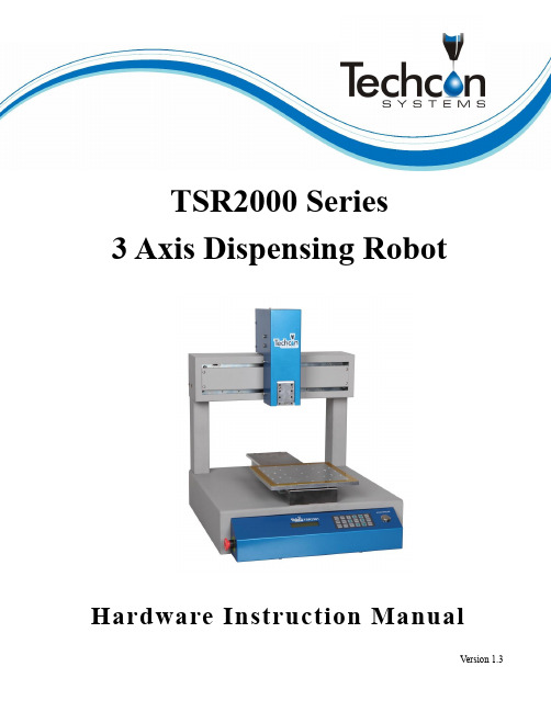
TSR2000 Series3 Axis Dispensing RobotHardware Instruction ManualCongratulations on the purchase of a Techcon Systems Automated Dispensing Robot. If you have not done so, see the installation guide provided with your system for installation instructions.Now that your dispensing system is ready to use, take a few moments to get to know the parts of your dispensing system and software. This manual is designed to help you use the robot as quickly as possible. We, here at Techcon Systems, hope you find this product beneficial. If you have any questions, please contact us at the details listed below:For Sales and Support:Techcon Systems Corporate Headquarters,10800 Valley View Street, Cypress, California, 90630, USA.Tel: 1-714-230-2398, Fax: 1-714-828-2001E-mail: *****************************Techcon Systems European Corporate Office,Eagle Close, Chandler’s Ford Industrial Estate,Eastleigh, Hampshire, SO53 4NF, UK.Tel: +44 2380 489 100, Fax: +44 2380 489 109E-mail: *********************************Or visit This manual is designed to provide information about Techcon Systems robot hardware. Every effort has been made to make this manual as complete and accurate as possible. There is no implied or expressed warranty as to the purpose, suitability or fitness of the information. The information is provided on as as-is basis. Techcon Systems reserves the right to improve and revise its products. This manual specifies and describes the product as it existed at the time of publication. As with any new programming software, a basic understanding of the vocabulary is necessary.Table of Contents1. Safety Instruction……………………………………………………………………..…….2. Summary………………………………………………………………………………..….. 2.1 Features……………………………………………………………………………… 2.2 Specifications………………………………………………………………………… 2.3 Unpacking and Inspection…………………………………………………………………………. 2.4 Instructions about the Keypad………………………………………………….……. 2.5 Course of the File Processing…………………………………………………….………3. Setup and Connection……………………………………………………………………… 3.1 Setup………………………………………………………………………………… 3.1.1 How to Connect a Syringe Dispenser with Interface Cable……………………. 3.1.2 How to Connect a Valve Controller with Interface Cable…………………… 3.1.3 How to Connect a Jet Valve Controller with Interface Cable ……..………………… 3.1.4 Testing the Interface Connections …………………………..……………….. 3.2 I/O Socket Instruction………………………………………………………………… 3.2.1 Circuit Diagram of I/O Socket………………………………………………… 3.2.2 Four Pin Socket “Pin Out”……………………………….………………….… 3.2.3 Five Pin Socket “Pin Out”……………………………………………………. 3.2.4 Seven Pin Socket “Pin Out”……………………….………………………….. 3.3 Instructions For DB37 Socket………………………………………………………… 3.3.1 Pin Instruction of DB37………………………………………………………. 3.3.2 Circuit Diagram of DB37……………………………………………………… 3.4 Instruction of Input & Output………….……………………………………………. 3.4.1 IO Function Definition………………………………………………….……… 3.4.2 IO Function Instruction…………………………………………………………. 3.5 Operation For First Time……………………………………………………………….. 4. Off-Line Operation Interface………………………………………………………….……. 4.1 Off-Line Initialization………………………………………………………………… 4.2 Off- Line File Processing Interface…………………………………………….…….. 4.2.1 Select Processing File…………………………………………………………… 4.2.2 File Process……………………………………………………………….…….. 4.2.3 Stop the File Processing……………………………………………………… 4.2.4 File Processing Count & State………………………………………………….. 4.3 Off-Line Origin Calibration Interface…………………………………………….….. 4.4 Off-Line Loop-Work Parameter Setting Interface………………………………….... 4.5 Off-Line Testing Interface…………………………………………………….……….. 4.6 Times of Nozzle Interface………………………………………………………………5. Mounting and Bracketry………………………………………………………………...….…. 5.1 Tool Plate - Valve Mounting Bracket……………………………………….………….. 5.2 Base Plate - Product Mounting Plate……………………………………………………. 5.3 Syringe Mounting Bracket - Attachment.........………………………………………6. Trouble Shooting…………………………………………………………………….…….7. Warranty……………………………………………………………………………………..8. Manufacturer’s Declaration of Incorporation………………………………………...……………9. Manufacturer’s Declaration of Conformity…………………………………………..………….4 5-95 678 9 9-209 10 10 10 11 12-1312 13 13 13 14-1614 15-16 16-2017-18 18-20 20 21-2321 21 21 22 22 2222 23 23 23 2424 24 25 26 26 27 281.SAFETY INSTRUCTIONCaution about the main unit●Only use this robot with correct rated voltage and frequency (refer to the markings on the back of equipment).●Do not move the XY moving plate and the top head, by hand. This will protect them from damage.●During processing, do not touch the moving parts.●Before use, check the heating controller and pressure reduction valve have been fastened reliably (if fitted).●Keep the unit dry. Do not use or disconnect the equipment with wet hands.●If an emergency event occurs, press the emergency switch (red) immediately. The main unit will cut off thepower and stop processing the dispensing file.Caution about the power cord●This machine is equipped with a 3-wire grounding plug and must be plugged into a 3-terminal grounded socket.Do not modify the plug or use an ungrounded power socket. If an extension cord is necessary, use only a 3-wire extension cord that provides grounding.●Do not turn on the power of the machine if any parts are damaged, especially if the power cord is damaged.Caution about the teaching pendant●Do not connect the teaching pendant during a profile. When disconnecting the teaching pendant, loosen andremove the fixing screws and then pull out it, once the profile has finished.●For protecting the teaching pendant, from damage, do not drop it on the floor or shake it intensively.Caution about the air supply●Ensure the air flow is dry and clean. Select a suitable air pressure according the application. Suggested airpressure is no more than 100 psi (6.9bar).●During use, do not over bend or over rotate the air tubes.2. SUMMARYThis desktop robot is designed for the automated operation for dispensing fluid. It is a fully automatic and features a high-resolution control system with 3 axis. This unit provides the operator with easy programming instructions, increased parameters, a larger memory space and a higher speed, which highly improves productivity.Note: the illustration may have some differences with each application. The dispensing equipment, such as a dispensing valve, syringe, cartridge, etc. are optional.2.1 Features● Comprehensive 3-dimensional drawing support, such as 3-dimensional linear interpolation, capabilities ofteaching 3D graphics and user-defined 3D array. ● Capability to save mass files.● User-defined array function: easy solution for mould deviation. Supports user-defined 3D array. Smoothingfunctions of changing speed and hi-speed trajectory whilst moving. User-definable speed parameters. ● Group function: this function allows operators to copy, delete, modify, array, and pan multi-points.● Advanced teaching pendant that supports functions, such as array, group edit, sub-procedure, condition-callprocedure etc.● Unique merge function: easy resolution to process complex multi-layers, irregular array and non-array graphics. ● Multiple processing modes, such as single-step operation, overall processing and automatic loop processing.Communication Interface: Connect with teaching pendent2.2 Specifications* The specifications are subject to change without notice.2.3Unpacking and Inspection2.4 Instructions about the Keypad - the keypad, on the robot face, can be used when the teaching pendant isdisconnected.For Further functions and detailed use of the buttons refer to the chapter 4 “off-line operation instruction”.2.5Course of the File ProcessingTo complete a process file there needs to be three steps: program-adjust-process. For detailed operation refer to the “operation manual of the teaching pendant”.Program:The method of teaching a program.Adjust:Adjusting the programming file, such as origin calibration, slant array, height adjusts, file parameters a djust (including speed, acceleration, delay time, distance etc.)Process:Download the program file to the system, from the teaching pendant.The program is now complete and can be initiated.3.SETUP AND CONNECTION3.1 SetupConnecting air tubing: directly insert the air tube into the air connector, on the back of the controller. Removing air tube: press down the connector head and then pull out the air tube, from the controller.3.1.1 How to Connect a (TS250 or TS350) Syringe Dispenser with Interface CableTake the supplied TSR-VCABLE and connect the round female connector to the male “OUTPUT” connector on the rear of the robot. Take the opposite end and connect the female 9 pin connector to the DB9 connector on the rear of the TS250 or TS350 Series controllers.3.1.2 How to Connect a (TS500R) Valve Controller with Interface CableTake the supplied TSR-VCABLE and connect the round female connector to the male “OUTPUT” connector on the rear of the robot. Take the opposite end and connect the female 9 pin connector to the DB9 connector on the rear of the TS500R controller.3.1.3 How to Connect a (TS920) Jet Valve Controller with Interface CableTake the optional TSR-DJETCABLE and connect the round female connector to the male “OUTPUT” connector on the rear of the robot. Take the opposite end and connect the male 26 pin connector to the rear of the TS920, jet valve controller, marked I/O.4443.1.4 Testing the Interface ConnectionsTS250, TS350, TS500R and TS920 with TSR-VCABLE and TSR-DJETCABLE – 1 Dispense Head in UseTS250, TS350 and TS500R with TSR-VCABLE – Multiple Dispense Heads in UseThe TSR2000 Series robot is capable of operating up to 4 dispensers/controllers during a program. An optional cable is made available for this function. Please contact Techcon if this specialty cable is required. Follow the instructions, below, to test the other available outputs.Press 4 Press By pressing button 1, the controller will activate. If the system is complete and under pressure, fluid will exit out of the dispense outlet. Press 1 to turn off output. To go back to main screen, press multiple times. to main Legend:Output not activated Output activated3.2I/O Socket Instruction3.2.1 Circuit Diagram of I/O SocketInsideInside3.2.2 Four Pin Socket “Pin Out” - the following list describes the pin function of the four-pin socket.Note: *If a special function is required, the input and output signal can be set again.3.2.3 Five Pin Socket “Pin Out”- the following list describes the pin function of the five-pin socket. The socketcan connect with a photo-electricity switch etc.Note: *If a special function is required, the input and output signal can be set again.3.2.4 Seven Pin Socket “Pin Out” - the following list describes the pins function of the seven-pin socket. By thesocket, it can control the external device.Note: *If a special function is required, the input and output signal can be set again.3.3 Instructions For DB37 SocketNote: The DB37 socket is an optional fitting and must be ordered separately if required.3.3.1 Pin Instruction of DB37(socket of DB37)3.3.2 Circuit Diagram of DB373.4 Instruction of Input & Output● The following input interfaces and output interfaces are corresponding to the signal pins which are defined as “Min, Mout, Ein, Eout” at the above socket. It also corresponds to the interface at the “IO Test” display window.● After setting, the function of IO interface can be tested at the “IO Test” display window.● The interfaces, in the following table, can be set at the “Input Config” or “Output Config” of “System Config 2” of teaching pendant. It can define the special function for the following input & output interfaces which are corresponding to the above sockets.Connection of DB37 plug3.4.1IO Function Definition1.In the “Input Config 2” displaying window, it can set the input interface: Min1~Min4 & Ein1-8 & Ein 09~Ein16.2. In the “Output Config 2” display window, the input interface can be set: Mout1~Mout4, Eout09~Eout16.Output Interface Optional FunctionMout1~Mout4 --, Nozzle 1, Nozzle 2, Nozzle 3, Nozzle 4, Working Flag, WorkEnd Flag, Cylinder, Clean OutputEout09~Eout16--, Ready Flag, Alarm Flag, Working Flag, WorkEnd Flag, Cylinder, Clean Output3. In the teaching pendant, “Eout09~Eout16” are corresponding to the “Eout8+ (0~8)” at the “IO Test” and“Output (point)” displaying window.IO TestMout :F132410+324176853247685324768532418+1Eout :F2Eout :F3Min :Ein :3247685Ein :0+8+11Namely, “Eout8+ 1” is the output interface “Eou09”. “Eout8+ 2” is the output interface “Eou10”. “Eout8+ 3” is the output interface “Eou11”, etc.3.4.2 IO Function InstructionFunction of InputFunction Instruction-- N/A.Origin BTN Input the reset signal into the unit by corresponding signal pin, and the unit will run the reset (ORG) operation.Stop BTN Input the stop signal into the unit by corresponding signal pin, and the unit stops the current operation.Start BTN Input the start signal into the unit by corresponding signal pin, and the unit starts to work or pauses the current work.Foot BTN Input the foot switch signal into the unit by corresponding signal pin and the unit runs the foot switch operation and the function is similar with the “Start BTN”.Test input-LInput the signal “breakover ground” into the unit by corresponding signal pin and the unit comes into the testing state (cannot move and can only be programmed).Mout/Eout/Min/Ein is corresponding to the “metal socket” at the back of robot. Can be test before operation .Note:●The function settings of input & output cannot be accessed by the operator. It can only be operated by themanufacturer.●Will not give advanced information if some functions are changed.3.5Operation For First Time UseIf using the unit for the first time, the operator should test the basic functionalities.Step 1: Install and TestBefore using, the operator should properly install and connect the system. The operator should test the basic functionalities of the system with the ‘Test’ function on the teaching pendant. Test should include if there are any problems with the axis movements towards positive or negative directions.Step 2: Parameters SettingCorrectly set the global parameters and other parameters being used in the process.Remark: Failure to properly set the parameters will cause difficulties in using the system.Step 3: Teaching ProgramProgram a profile with teaching pendant. Refer to the instruction manual of the teaching pendant.Step 4: Origin Calibration & Setting the Parameters of the Teaching Pendant1.Origin calibration: The operator should adjust the start point when a teaching file is created for the first time.2.Set file parameters.Step 5: Download & Process1.Download: refer to instruction manual of the teaching pendant “Teaching File Download”.2.Process: refer to instruction manual of the teaching pendant “File Processing”.4. OFF-LINE OPERATION INTERFACE4.1 Off-Line Initialization1. When the system is turned on without connecting to the teaching pendant, the LCD will enter initialization interface automatically (Refer to Fig.4-1).2. After 5 seconds, the initialization is complete and the system enters into the file processing interface.4.2 Off- Line File Processing Interface1. After initialization, the system will enter the “Processing Interface”. This interface is frequently used when notconnected to the teaching pendant. Enter into the other settings interface through the processing interface.2. In the circulating processing interface, the LCD will display information such as “already processed times /setprocessing times”.All information showing on the LCD display are as follows:the Loop-WorkProcessing Times3. 4. 5. 6. will not be saved.7.4.2.1Select Processing File1.2.Fig. 4-1: Initialization Interface4.2.2File Processthe paused processing file and the file state changes to “WORK”.Emergency Switch: S tops file processingand cuts off the power supply of the driver, the LCD displays4.2.4 File Processing Count And State1. the digit to 0.2. At the lower right corner of processing interface, the file processing state is displayed. The processing state ischanging with the processing course. The file processing state shown in the table below:Table 4-1: File Processing State4.3 Off- Line Origin Calibration Interface1. During the file processing, the deviation can be calibrated between the processing file and the real route by theorigin calibration.2.X/Y/Z/R displays the tips current position. “MID” means the current processing speed is in the middle.3. Orientation4.5. Adjust the point’s speed:6. Calibration interface. If press button, save the calibration result, and directly return file processing interface.4.4 Off- Line Loop-Work Parameter Setting Interface1.2.Press the button at the processing interface and then enter into the “loop–work parameter settinginterface”.Fig.4-5: Loop–work Parameter Setting Interface3.4.After completing adjust, press thebutton and return tothe file processinginterface. When the “N=0000” or is displayed, without loop workprocessing and the file only processes one time.Fig. 4-6: Testing Interface4.6 Times of Nozzle Interfacebeen used and maximal limit times. The interface only can be viewed and cannot be set. Setting methods need refer “teaching pendant”. “*****/*****”: The front digits mean the used times, the latter digits mean the maximal limit times. When used times have reached the maximal limit times, the system will alarm and advise to change the nozzle. If the latter digit is “00000”, this means that it does not limit the using times of nozzle.Fig. 4-7 Times of Nozzle InterfaceN : Loop processing times setT : Loop processing interval times set Rn : Reset after loop N times5. MOUNTING AND BRACKTRY5.1 Tool Plate - Valve Mounting Bracket5.2 Base Plate – Product Mounting Plate5.3 Syringe Mounting Bracket – AttachmentFrom the main screen, on the teaching pendant, press 4. Use the jog keys to move the head into a central position and lower head until there is sufficient access to the rear of the bracket. Use SHF button to change movement speed. Follow instructions below.1. Move and lower head using teachingpendant. 2. Remove mounting plate.4. Attach attach top bracket.3. Secondary plate should be exposed 5. Attach bottom bracket from behind. 6. Install syringe and lightly tighten thumb screws.6. TROUBLE SHOOTING1.The System cannot Reset after Booting.Emergency switch errorCheck the Emergency switch is not pressed, by mistake.2.Z axis or X and Y axis cannot be Positioned Accurately in Processing1) Loss of steps will cause inaccurate positioning phenomenon.Overload, excessive speed or acceleration, insufficient power supply, or mismatched motor drive would lead to the loss of steps. Please check the overload and the parameters settings. If the inaccurate positioning phenomenon disappears or remits after reducing the speed or acceleration, we can make sure the phenomenon is caused by the motor loss of steps. If inaccurate positioning phenomenon is very obvious for one axis, reduce the acceleration of the axis.2) Operation Error will cause inaccurate positioning phenomenon.Do not reset when the work doneMake the system reset automatically after each accumulated processing error has been eliminated,)7. WARRANTYManufacturer warrants this product to the original purchaser for a period of one (1) year from date of purchase to be free from defects in material and workmanship, but not against damages by misuse, negligence, accident, faulty installations and instructions. Manufacturer will repair or replace (at factory’s option), free of charge, any component of the equipment thus found to be defective, on return of the component, “PREPAID” to the factory during the warranty period. In no event shall any liability or obligation of the Manufacturer arising from this warranty exceed the purchase price of the equipment. This warranty is only valid if the defective product is returned as a complete assembly without physical damage. The Manufacturer’s liability, as stated herein, cannot be altered or enlarged except by a written statement signed by an officer of the company. In no event shall the Manufacturer be liable for consequential or incidental damages. A return authorization is required from Techcon Systems prior to shipping a defective unit to the factory.Manufacturer reserves the right to make engineering product modifications without notice.All returns must be issued with a Returns Authorization number, prior to return. Send warranty returns to:Techcon Systems Corporate Headquarters,10800 Valley View Street, Cypress, 90630, USA.Tel: 1-714-230-2398, Fax: 1-714-828-2001E-mail: *****************************Techcon Systems European Corporate Office,Eagle Close, Chandler’s Ford Industrial Estate,Eastleigh, Hampshire, SO53 4NF, UK.Tel: +44 2380 489 100, Fax: +44 2380 489 109E-mail: *********************************Jimmy Guo Quality EngineerJimmy Guo Quality Engineer。
点胶机控制系统使用说明

点胶机控制软件(3轴)操作手册长沙市两湖机电设备有限公司1,联机及断开连接运行本软件,首先要进行连接设备操作,连接操作按钮为.当联机成功后就可以进行加工了,在加工完成后,不使用本软件后请先断开与设备的连接,断开连接按钮为.本软件支持dxf,plt,ai,dst,nc 格式的加工文件3.调试当需要对机器设备进行调试的时候,可以打开调试面板,该面板可以查看到各个IO的状态,从而获取到设备的状态。
4.参数设置1)用户参数手动速度,点动速度主要是设置手动控制时的运行速度的,可以设置低速、常速、高速三个速度段开机回零提示,是指在系统启动后,没有进行过回零操作,系统将会提示用户是否回零,取消选择将不会提示。
加工完成后自动回原点,是指加工完成后,设备将自动运行到工件的原点位置。
2)设备参数丝杆导程,指步进电机旋转一周所走的路程,请根据设备的具体情况设置脉冲数,是指步进电机旋转一周所需要的脉冲数,请根据设备的具体情况设置马达方向,是指马达旋转的方向,请根据设备具体情况设置回零方向,是指设备回零的方向,请根据设备的具体情况设置回零速度,是指设备回零时的速度空行速度,是指设备空移时的速度机床尺寸,是指设备运行的最大范围软极限有限,指是否通过软件限制设备运行的范围进给速度,是指运行时线性加工的速度Z的安全高度,指当设备空移时Z轴最低高度3)显示设置设置加工文件的显示样式4)加工配置设置加工控制的IO,加工起始IO状态、加工结束IO状态是设置加工线段前控制IO的控制状态;加工起始前延时是加工线段时IO控制前的延时,加工起始后延时是IO控制后延时,加工结束前延时和加工结束后延时与加工前一样。
5.手动控制手动控制可以分为低速、正常、高速三个速度运行,通过手动控制移动到指定位置,通过置零按钮可以设置当前工件原点所在位置。
6.回零回零是指重新确定设备机械零点的位置,该操作指需进行一次7.运行当加工文件已打开且加工范围在有效范围内,运行按钮就可激活,运行时点击即可。
点胶机说明书
点胶机简易说明书
一、定义:
点胶机是各种流体的精密定量输送、涂胶、灌封等作业的典型应用,由微量泵和控制系统组成。
可选型号:
点胶机:eco-PEN300;eco-PEN450; eco-PEN600
控制器:EC 200-K;EC 200-B
二、点胶机技术特性:
1、节约30%的胶水使用量
2、最小流量可达0.001ml,精度1%
3、具备回吸功能,完全避免介质滴漏、拉丝问题
4、最小2Bar的自密封功能(随介质粘度上升而上升)
5、计量压力可达16—20Bar
6、可配用极小的胶嘴或针嘴进行高精密输胶
7、具有自吸功能(适用于高粘性介质)
8、对可自流的介质不需加装任何压力罐装置
9、容积式输送,流量恒定(不受外界因素变化影响)
10、驱动与泵体部分相互隔离
11、模块化设计,易于安装、使用、清洗、维护。
12、快速插接头设计,易于根据现场需要求行调整
三、点胶机应用范围
各种溶济、粘接剂、油漆、化学材料、固体胶等,包括硅胶、EMI导电胶、UV 胶、AB胶、快干胶、环氧胶、密封胶、热胶、润滑脂、银胶、红胶、锡膏、散热膏、防焊膏、透明漆、螺丝固定剂、木工胶、厌氧胶、亚克力胶、防磨胶、水晶胶、灌注胶、喇叭胶、瞬间胶、橡胶,油漆、搪瓷漆、亮漆、油墨、颜料等
四、点胶机应用领域
手机按键、印花、开关、连接器、电脑、数码产品、数码相机、MP3 、MP4 、电子玩具、喇叭、蜂鸣器、电子元器件、集成电路、电路板、LCD液晶屏、继电器、扬声器、晶振元件、LED灯、机壳粘接、光学镜头、机械部件密封等。
五、推荐品牌Preeflow。
- 1、下载文档前请自行甄别文档内容的完整性,平台不提供额外的编辑、内容补充、找答案等附加服务。
- 2、"仅部分预览"的文档,不可在线预览部分如存在完整性等问题,可反馈申请退款(可完整预览的文档不适用该条件!)。
- 3、如文档侵犯您的权益,请联系客服反馈,我们会尽快为您处理(人工客服工作时间:9:00-18:30)。
目录第一章概述 (3)1.1硬件 (3)1.2 软件 (4)1.3 配件 ............................................................................................. 错误!未定义书签。
1.4 主板尺寸(单位:mm)............................................................. 错误!未定义书签。
1.5 手持编程器尺寸(单位:mm).................................................. 错误!未定义书签。
第二章主界面及按键说明 .. (5)2.1 主界面说明 (5)2.2 手持编程器按键说明 (6)2.3 程序选择及对针按键说明 ............................................................ 错误!未定义书签。
第三章编程的基本方法说明 . (9)3.1 单位符号解释 (9)3.2 点胶程序结束的约定 (9)3.3 点胶程序运行方式 (9)3.4 点胶的基本路径组成 (10)第四章菜单1 (12)4.1 第1页1.文件名编辑 (12)4.2 第1页2.生成默认点胶参数 (13)4.3 第1页3.编辑多个编程点 (13)4.4 第1页4.设置标号 (17)4.5 第1页5.阵列点胶 (17)4.6 第1页6.阵列展开操作 (19)4.7 第1页7.调用子程序 (19)4.8 第1页8.调用文件 (19)4.9 第1页9.程序跳转 (19)4.10 第2页1.有限次数循环 (20)4.11 第2页2.程序结束或返回 (20)4.12 第2页3.延时 (20)4.13 第2页4.暂停 (20)4.14 第2页5.输入信号编程 (21)4.15 第2页6.输出信号编程 (21)4.16 第2页7.方形涂胶 (21)4.17 第2页8.圆形涂胶 (22)4.18 第2页9.点胶信号开/关 (22)4.19 第3页1.工件计数器 (22)4.20 第3页2.回空闲停留位置 (22)4.21 第3页3.回原点 (22)第五章菜单2 (22)5.1 第1页1.对针点设置 (23)5.2 第1页2.校准对针点 (23)5.3 第1页3.胶枪下移限制值设置 (23)5.4 第1页4.空闲停留点坐标设置 (23)5.5 第1页5.胶枪提起高度设置 (23)5.6 第1页6.空移速度设置 (24)5.7 第1页7.提前出胶时间设置 (24)5.8 第1页8.线段点胶速度设置 (24)5.9 第1页9.线段点胶拉丝参数设置 (25)5.10 第2页1.线段点胶时间参数设置 (25)5.11 第2页2.单点点胶参数设置 (25)5.12 第2页3.急停时输出信号设置 (26)5.13 第2页4.输出信号初始化设置 (26)5.14 第2页5.空闲滴胶时间设置 (26)5.15 第2页6.匀速调试速度设置 (26)5.16 第2页7.工件计数器设置 (26)第六章菜单3 (27)6.1 第1页1.针头移动到指定坐标 (27)6.2 第1页2.文件复制 (27)6.3 第1页3.DXF文件转换 (28)6.4 第1页4.对当前文件锁定/解锁 (28)6.5 第1页5.对机器高级锁定/解锁 (28)6.6 第1页6.当前文件锁定密码设置 (28)6.7 第1页7.机器高级锁定密码设置 (28)6.8 第1页8.输入口名称编程 (29)6.9 第1页9.输出口名称编程 (29)6.10 第2页1.按键声音设置 (29)6.11 第2页2.速度优先等级设置 (29)6.12 第2页3.小键盘锁定/解锁 ........................................................ 错误!未定义书签。
6.13 第2页4.浏览文件名 ................................................................. 错误!未定义书签。
第一章概述概述……ARM,DSP,FPGA,彩屏1.1硬件2.电机轴输出:5轴输出,分别为XYZ三维坐标轴,A轴旋转轴,实现双Y轴功能的Y2扩展轴,可实现带旋转轴的双Y轴点胶机台控制。
3.加减速特性:S型曲线加减速模式,加减速加速度独立设置;10K的速度刷新频率,让机械响应性能更好,噪音更小。
4.脉冲输出频率:4MHz的直线插补,2MHz的圆弧插补(包括三轴空间圆弧插补),以电机每转20000个脉冲为例,可达到6000转/分,足以满足现有的高速伺服电机5000转/分的要求。
5.原点、限位输入:每个电机轴带独立专用的原点输入、正负限位输入,无需占用可编程通用输入的硬件资源。
6.可编程输入输出:各12路独立专用的可编程输入输出,均采用光耦隔离,每路输出电流最大可达500mA。
7.支持3位拨码盘或3位数码管接口,两种方式任选(菜单设置),可快速选择切换0-999的1000个点胶文件。
8.对针用小键盘,在无手持编程器时也可以方便实现因换针头引起的误差进行校正。
9.功能键:有‘运行/暂停’、‘停止’、‘回原点’、‘出胶测试’、‘单步测试’五个功能按键,并有相应的指示灯控制输出;具有‘紧急停止’按钮输入。
10.具有CAN总线、RS-232、网口,可给有特殊需要的客户定制专用程序。
11.U盘读写功能:使用FAT32文件系统,不再受大于2G容量的U盘无法格式化成FAT格式的限制。
12.存储空间:主板256MB,可存储1000个点胶文件,每个文件4000个编程点;手持编程器16MB,可存储开机画面,点胶文件,在多台机器互相拷贝点胶文件尤其有用。
13.手持编程器屏幕:采用480 X 272像素、1600万色真彩色4.3寸液晶显示屏,让操作菜单界面及开机画面的内容更加丰富。
14.工作电压:DC 24V15.工作环境:温度0℃--45℃,湿度%40--80%16.存储环境:温度-40℃--60℃,湿度0%--95%1.2 软件1.三维空间直线插补、三维空间圆弧插补。
2.双Y功能,Y轴切换时无需做回原点动作。
3.具有A轴旋转轴,旋转轴可与XY路径切线跟随。
4.拐角处理可以设定速度与路径吻合度的优先级,实现拐的平滑过渡。
5.DXF文件转换功能,可将CAD做好的点胶路径图导出DXF文件转成点胶文件。
6.对编程点的编辑可有30次的“撤销”“重做”,有效防止误操作。
7.点胶参数设置以编程点的方式设置,可实现在同一个点胶加工过程中不同区域有不同的点胶参数设置。
8.在回原点动作时各轴回到原点后XYZ三个轴同时进行原点捕获动作。
9.具有全拼中文输入法。
第二章主界面及按键说明2.1 主界面说明1.主界面内容分布说明。
2.点胶文件序号及文件名,“030”为序号,“点胶程序030”为文件名。
3.点胶文件最新被修改的时间。
4.打开点胶文件图标,可用“切换”按键将光标切换到该图标。
5.“撤销”“重做”状态指示图标,可达到30次的“撤销”“重做”次数,如该图标为灰色则无可操作的“撤销”或“重做”。
6.表示该点胶文件被编辑过,需要做“除错”操作,如该图标为灰色则该文件已“除错”通过。
7.该文件未锁定,该文件已被锁定,器已被锁定。
8.运行模式,分“工作”、“无胶”、“匀速”三种模式;“工作”模式为正常的点胶加工模式;“无胶”模式为机器的运动速度和路径跟“工作”模式一样,但不出胶;“匀速”模式为机器的运行路径跟“工作”模式一样,但按“匀速”模式的速度运行,且不出胶,主要用于路径的测试。
9.动移动速度,分“快、中、慢”速,按“速度”键轮流切换。
10.工件计数器,前面的数值为工件计数值,后面的数值为设定要加工的工件数,如工件计数值达到设定要加工的工件数值则会提示工件计数已满;如无工件计数限制再将要加工的工件数设为“0”。
11.U盘插入,无U盘插入。
12.拼音输入、数字输入、小写字母输入、大写字母输入,在字符输入状态下按“#”键可以切换输入法。
2.2 手持编程器按键说明1.手动第4轴A轴逆时针旋转。
2.手动第4轴A轴顺时针旋转。
3.手动Z轴向上移动。
4.手动Z轴向下移动。
5.手动Y轴向前移动。
6.手动Y轴向后移动。
7.手动X轴向左移动。
8.手动X轴向右移动。
9.手动移动速度“慢、中、快”速切换。
10.退出菜单状态或取消输入对话框的操作。
11.光标在“点胶编程点”区域和“快捷菜单栏”之间切换,在预览时变换平面。
12.执行分析当前点胶文件的点胶编程点是否合符点胶编程要求,如符合点胶编程要求则图标会变成灰色。
13.按下该按键则弹出当前界面状态下的一些帮助信息,按任意键退出信息。
14.预览当前点胶文件XY、XZ、YZ平面的出胶路径图形,按键变换平面,按其它任意键退出信息。
15.对编程点编辑的撤销和重做,可有30次操作,有效防止误操作。
16.在光标选定的编程点前面插入一个空白点胶编程点。
17.主界面下删除光标选定的编程点,或菜单输入状态下做删除键用。
18.快捷进入编程点光标跳转对话框。
19.进入菜单1,菜单1主要为执行点胶动作的编程点,编程点显示为黑色。
20.进入菜单2,菜单2主要为点胶参数设置的编程点,编程点显示为暗红色。
21.进入菜单3,菜单3主要为设备的参数设置以及一些应用操作等。
22.执行回原点动作。
23.执行单步点胶测试动作。
24.点胶加工开始运行或暂停。
25.点胶加工停止。
26.主界面下编程点光标上移一页,菜单界面下菜单上翻一页。
27.主界面下编程点光标下移一页,菜单界面下菜单下翻一页。
28.主界面下编程点光标上移一行,菜单界面下菜单上移一行,输入对话框状态下光标上移一行。
29.主界面下编程点光标下移一行,菜单界面下菜单下移一行,输入对话框状态下光标下移一行。
30.主界面下为线段点胶开始点快捷编程,在输入对话框状态下为字符输入或数字‘1’输入。
31.主界面下为线段点胶中间点快捷编程,在输入对话框状态下为英文字母‘abc’输入或拼音‘abc’输入或数字‘2’输入。
32.主界面下为线段点胶结束点快捷编程,在输入对话框状态下为英文字母‘def’输入或拼音‘def’输入或数字‘3’输入。
33.主界面下为单点点胶快捷编程,在输入对话框状态下为英文字母‘ghi’输入或拼音‘ghi’输入或数字‘4’输入。
34.主界面下为线段点胶圆弧点快捷编程,在输入对话框状态下为英文字母‘jkl’输入或拼音‘jkl’输入或数字‘5’输入。
35.主界面下快捷进入圆形点胶编程,在输入对话框状态下为英文字母‘mno’输入或拼音‘mno’输入或数字‘6’输入。
