SmartPlant Review 使用手册 (中文版)
SPS Smart Manual Profiler 说明书
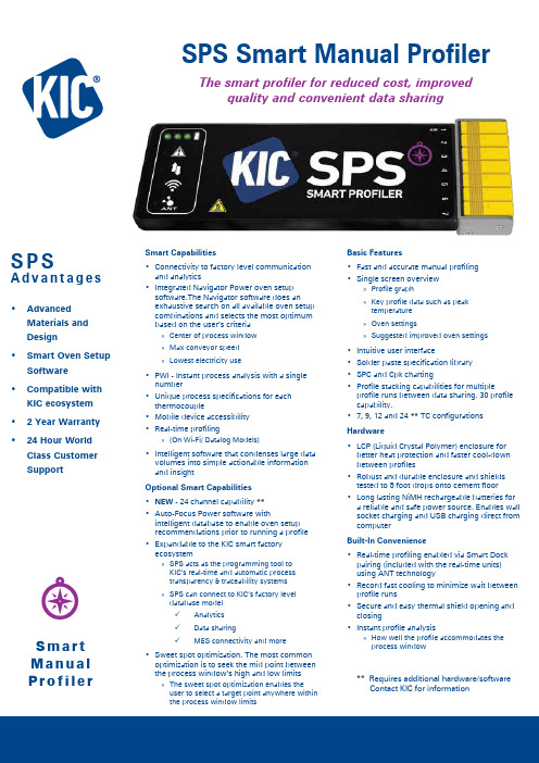
S P SA d v a n t a g e s• AdvancedMaterials and Design• Smart Oven SetupSoftware • Compatible withKIC ecosystem • 2 Year Warranty • 24 Hour WorldClass Customer SupportS m a r t M a n u a l Pr o f i l e rM Ov SmarSPS Smart Manual ProfilerThe smart profiler for reduced cost, improvedquality and convenient data sharingSmart Capabilities• Connectivity to factory level communication and analytics • Integrated Navigator Power oven setup software.The Navigator software does an exhaustive search on all available oven setup combinations and selects the most optimum based on the user’s criteria»Center of process window »Max conveyor speed »Lowest electricity use• PWI - Instant process analysis with a single number • Unique process specifications for each thermocouple • Mobile device accessibility • Real-time profiling»(On Wi-Fi/ Datalog Models)• Intelligent software that condenses large data volumes into simple actionable information and insightOptional Smart Capabilities• NEW - 24 channel capability **• Auto-Focus Power software withintelligent database to enable oven setup recommendations prior to running a profile • Expandable to the KIC smart factory ecosystem»SPS acts as the programming tool to KIC’s real-time and automatic process transparency & traceability systems »SPS can connect to KIC’s factory level database model9Analytics 9Data sharing9MES connectivity and more• Sweet spot optimization. The most common optimization is to seek the mid point between the process window’s high and low limits»The sweet spot optimization enables the user to select a target point anywhere within the process window limitsBasic Features• Fast and accurate manual profiling • Single screen overview»Profile graph»Key profile data such as peak temperature »Oven settings»Suggested improved oven settings• Intuitive user interface• Solder paste specification library • SPC and Cpk charting• Profile stacking capabilities for multipleprofile runs between data sharing. 30 profile capability.• 7, 9, 12 and 24 ** TC configurationsHardware• LCP (Liquid Crystal Polymer) enclosure for better heat protection and faster cool-down between profiles • Robust and durable enclosure and shields tested to 5 foot drops onto cement floor • Long lasting NiMH rechargeable batteries for a reliable and safe power source. Enables wall socket charging and USB charging direct from computerBuilt-In Convenience• Real-time profiling enabled via Smart Dock pairing (included with the real-time units) using ANT technology • Record fast cooling to minimize wait between profile runs • Secure and easy thermal shield opening and closing • Instant profile analysis»How well the profile accommodates the process window** Requires additional hardware/software Contact KIC for informationSPS Smart Profiler Kit Contents Smart Profiler Software on USB Flash Drive Smart Dock (Wi-Fi - ANT)*USB Software Protection DongleUSB Cable (A-Male/Micro-B)Electronic User Manual Thermal Shield*Electronic Hardware Guide Gloves Getting Started Guide Thermocouples*Calibration CertificateScissors Carrying Case Power Supply * These items may vary according to specific models ordered.Accuracy: ...........................±0.5°C Resolution: .........................0.1°C Internal Operating Temp: ..0°C to 85°CSample Rate: ......................0.002 to 50 per secondData Points: ........................72K per channelTemperature Range: ..........-150°C to 1050°C PC Connection: B 2.0 (Std-A/Micro-B)Power: ..............................Internal rechargeable NiMH batteryUSB cable connected to PC or power supply10 minute fast recharge for a single profileWi-Fi: ...................................2.4 GHzANT: ....................................2.4 GHz Thermocouple Compatibility:7, 9, 12 Channel Unit: ..Type K, StandardDimensions (L x W x H mm):7-Channel Unit: ............188.0 x 60.0 x 17.0 9-Channel Unit: ............188.0 x 75.0 x 17.0 12-Channel Unit: ..........188.0 x 98.0 x 17.0Thermal Shields: ................See Temperature Tolerance Table below for specifications.Vacuum compatibility: ......1.12kPa (8.40 torr) up to 45 minutesNote: The SPS Smart Profiler software, Profiling Software 2G, may interface directly with some oven controllers, eliminating the need for manual setpoint data entry. Please consult your oven supplier for availability.Accuracy based on factory calibration.Making Ovens SmarterTC #1TC #2TC #3Profiling Reduced to a Single NumberThe PWI measures the profile’s fit to the process window in a mathematical and objective manner by using a single number. This aids in optimizing the process by comparing and ranking alternative profiles in terms of their fit to the available process window. The lower the PWI, the more efficient and stable the process! (See the PWI data sheet for a detailed explanation)Copyright © KIC. All rights reserved. Patents pending. Specifications subject to change without notice . KIC and KIC Thermal Profiling are divisions of and registered trademarks and tradenames of Embedded Designs Inc. RPI i4.0, SPS, Smart Dock, X 5, KIC Start 2, K 2, KIC Explorer, SlimKIC 2000, KIC 24/7, KIC 24/7 Wave, KIC Vision, KIC Navigator Power, KIC Auto-Focus, KIC Auto-Focus Power, KIC RPM, KIC Carrier, Wave Surfer, KIC MVP, RPI, Process Window Index, PWI, the Lead Free Capable symbol, KIC ON BOARD and the KIC logo are trademarks or registered trademarks of KIC. All other trademarks and tradenames are the property of their respective holders.Corporate Headquarters16120 West Bernardo Drive • San Diego, CA 92127 USA +1(858)673-6050 Phone • +1(858)673-0085 FAX *****************•****************European Regional Office************************•***********************Asian Regional Office**********************•********************* All KIC products are designed to give maximum value and fast payback by streamlining your thermal process. Investment in a KIC product is a step toward total process control and quality management. All KIC products come with a no questions asked, 30-day money back guarantee.Minimum System RequirementsDual Core / 1 GHz Processor PC with 2 GB RAM 2 GB available storageVideo 1024 x 768 resolution / 16-bit1 available USB port (for data download or Smart Dock)1 available USB port (for software protection dongle)Visit our website at /support-download/os-compatibility-chart for product compatibility with Windows operating systems.Rev 2206BDatalogger Model: data are downloaded to the computer through a USB cable after the run.Wi-Fi Model: data are sent via Wi-Fi to the computer in real-timeduring the run. Data are also stored internally for USB download after the run.。
罗克韦尔 PanelView Plus 6 Compact 终端 说明书

未经罗克韦尔自动化公司书面许可,任何单位或个人不得复制本手册之全部或部分内容。
在整本手册中,我们在必要的地方使用了以下注释,来提醒您注意相关的安全事宜。
警告:标识在危险环境下可能导致爆炸,进而导致人员伤亡、物品损坏或经济损失的 操作或情况。
Allen-Bradley、 Rockwell Software、 Rockwell Automation、 PanelView、 FactoryTalk、 RSLinx、 CompactLogix、 ControlLogix、 SLC、 MicroLogix、 PLC-5 和 RSView 是罗克韦尔自动化有限公司的商标。 不属于罗克韦尔自动化的商标是其各自所属公司的财产。
注意:标识可能会导致人员伤亡、财产损坏或经济损失的操作或情况的信息。注意符号 可帮助您确定危险情况,避免发生危险,并了解可能的后果。
重要信息 标识对成功应用和了解产品有重要作用的信息。
标签可能位于设备上或设备内,用于提供特定警示。
电击危险:位于设备 ( 例如,驱动器或电机 ) 表面或内部的标签,提醒人们可能存在危险 电压。
章节 3
访问配置模式 . . . . . . . . . . . . . . . . . . . . . . . . . . . . . . . . . . . . . . . . . . . . . . . . . . 33 终端设置 . . . . . . . . . . . . . . . . . . . . . . . . . . . . . . . . . . . . . . . . . . . . . . . . . . . . . . . 36 加载和运行应用程序 . . . . . . . . . . . . . . . . . . . . . . . . . . . . . . . . . . . . . . . . . . . 38 启动选项 . . . . . . . . . . . . . . . . . . . . . . . . . . . . . . . . . . . . . . . . . . . . . . . . . . . . . . . 39 桌面访问 . . . . . . . . . . . . . . . . . . . . . . . . . . . . . . . . . . . . . . . . . . . . . . . . . . . . . . . 42 通信设置 . . . . . . . . . . . . . . . . . . . . . . . . . . . . . . . . . . . . . . . . . . . . . . . . . . . . . . . 46 以太网连接. . . . . . . . . . . . . . . . . . . . . . . . . . . . . . . . . . . . . . . . . . . . . . . . . . . . . 48 文件管理 . . . . . . . . . . . . . . . . . . . . . . . . . . . . . . . . . . . . . . . . . . . . . . . . . . . . . . . 52 显示屏设置. . . . . . . . . . . . . . . . . . . . . . . . . . . . . . . . . . . . . . . . . . . . . . . . . . . . . 55 输入设备设置 . . . . . . . . . . . . . . . . . . . . . . . . . . . . . . . . . . . . . . . . . . . . . . . . . . 57 配置打印选项 . . . . . . . . . . . . . . . . . . . . . . . . . . . . . . . . . . . . . . . . . . . . . . . . . . 60 检查应用程序文件的完整性 . . . . . . . . . . . . . . . . . . . . . . . . . . . . . . . . . . . 62 配置诊断 . . . . . . . . . . . . . . . . . . . . . . . . . . . . . . . . . . . . . . . . . . . . . . . . . . . . . . . 63 查看和清除系统事件日志 . . . . . . . . . . . . . . . . . . . . . . . . . . . . . . . . . . . . . . 64 系统信息 . . . . . . . . . . . . . . . . . . . . . . . . . . . . . . . . . . . . . . . . . . . . . . . . . . . . . . . 64 启用或禁用报警显示画面 . . . . . . . . . . . . . . . . . . . . . . . . . . . . . . . . . . . . . . 66 时间和日期设置. . . . . . . . . . . . . . . . . . . . . . . . . . . . . . . . . . . . . . . . . . . . . . . . 67 区域设置 . . . . . . . . . . . . . . . . . . . . . . . . . . . . . . . . . . . . . . . . . . . . . . . . . . . . . . . 69 字体链接 . . . . . . . . . . . . . . . . . . . . . . . . . . . . . . . . . . . . . . . . . . . . . . . . . . . . . . . 72
smarty中文手册

Smarty 教 程 Copyright © by ispi of Lincoln, Inc. - 05/05/2007目 录一、模板设计 (1)1.基本语法 (1)Comments [注释] (1)Functions [函数] (1)Attributes [属性] (1)Embedding Vars in Double Quotes [双引号里值的嵌入] (2)Math[数学运算] (2)2.变量 (3)Variables assigned from PHP [从PHP分配的变量] (3)Associative arrays [关联数组] (4)Array indexes[数组下标] (4)Objects[对象] (5)Variables loaded from config files [从配置文件读取的变量] (6){$smarty} reserved variable [{$smarty}保留变量] (7)Request variables[页面请求变量] (7){$smarty.now} (8){$smarty.const} (8){$smarty.capture} (9){$smarty.config} (9){$smarty.section}, {$smarty.foreach} (9){$smarty.template} (9)3.Variable Modifiers [变量调节器] (10)capitalize [所有单词首字符大写] (10)count_characters[字符计数] (11)cat[连接字符串] (12)count_paragraphs[计算段数] (12)count_sentences[计算句数] (13)count_words[计算词数] (13)date_format[格式化日期] (14)default[默认值] (15)escape[编码] (16)indent[缩进] (17)lower [小写] (18)nl2br [换行符替换成<br />] (19)regex_replace [正则替换] (19)replace [替换] (20)spacify [插空] (21)string_format [字符串格式化] (22)strip [去除(多余空格)] (22)strip_tags [去除html标签] (23)truncate [截取] (24)upper [大写] (25)wordwrap [行宽约束] (26)bining Modifiers [组合使用变量调节器] (27)5.Built-in Functions [内建函数] (28)capture [获取页面输出] (28)config_load [配置加载] (29)foreach,foreachelse [循环处理数组] (31)include [包含文件] (36)include_php [包含PHP脚本] (37)insert [插入函数] (38)if,elseif,else (40)ldelim,rdelim [输出分隔符] (42)literal [文本处理] (42)php [嵌入php脚本] (43)section,sectionelse [遍历数组] (43)strip [去处首尾空格和回车] (55)6.Custom Functions[自定义函数] (56)assign [为模板变量赋值] (56)counter [计数] (56)cycle [轮转使用值] (58)debug [调试输出] (59)eval (60)fetch [取文件、HTTP、FTP] (61)html_checkboxes [html 复选框] (62)html_image [html 图片] (64)html_options [html下拉列表] (65)html_radios [html 单选框] (67)html_select_date [html 日期下拉列表] (69)html_select_time [html 时间下拉列表] (74)html_table [html 制表] (79)math [数学运算] (81)mailto (82)popup_init (84)popup [创建javascript弹出窗口] (85)textformat [文本格式化] (91)7.Config Files [配置文件] (95)8.Debugging Console [调试控制台] (97)二、Smarty For Programmers [程序员篇] (98)9.Constants [常量] (98)SMARTY_DIR [Smarty目录] (98)10.Variables [变量] (98)$template_dir [模板目录变量] (98)$compile_dir [编译目录变量] (98)$config_dir [配置目录变量] (99)$plugins_dir [插件目录变量] (99)$debugging [调试变量] (99)$debug_tpl [调试模板变量] (100)$debugging_ctrl [调试控制变量] (100)$global_assign [全局配置变量] (100)$undefined [未定义变量] (100)$autoload_filters [自动加载过滤器变量] (101)$compile_check [编译检查变量] (101)$force_compile [强迫编译变量] (101)$caching [缓存变量] (102)$cache_dir [缓存目录变量] (102)$cache_lifetime [缓存生存时间变量] (102)$cache_handler_func [缓存处理函数变量] (103)$cache_modified_check [缓存修正检查变量] (103)$config_overwrite [配置覆盖变量] (103)$config_booleanize [配置布尔化变量] (103)$config_read_hidden [配置读取隐藏变量] (104)$config_fix_newlines [配置固定换行符变量] (104)$default_template_handle r_func [默认模板处理函数变量] (104)$php_handling [PHP处理变量] (104)$security [安全变量] (105)$secure_dir [安全目录变量] (106)$security_settings [安全配置变量] (106)$trusted_dir [信任目录变量] (107)$left_delimiter [左结束符变量] (107)$right_delimiter [右结束符变量] (107)$compiler_class [编译类变量] (107)$request_vars_order [变量顺序变量] (107)$request_use_auto_globals [自动全局变量] (108)$compile_id [编译ID变量] (108)$use_sub_dirs [子目录变量] (108)$default_modifiers [默认修正器变量] (108)$default_resource_type [默认源类型变量] (109)11.Methods [方法] (109)append [添加] (109)append_by_ref [引用添加] (110)assign [赋值] (111)assign_by_ref [引用赋值] (111)clear_all_assign [清除所有赋值] (112)clear_all_cache [清除所有缓存] (112)clear_assign [清除赋值] (113)clear_cache [清除缓存] (113)clear_compiled_tpl [清除已编译模板] (114)clear_config [清除配置] (114)config_load [加载配置] (115)display [显示] (115)fetch [取得输出的内容] (117)get_config_vars [取配置变量的值] (118)get_registered_object [取得已注册的对象] (119)get_template_vars [取得模板变量的值] (119)load_filter [加载过滤器] (120)register_block [注册一个块] (121)register_compiler_function [注册编译函数] (122)register_function [注册函数] (123)register_modifier [注册修饰器] (123)register_object [注册对象] (124)register_outputfilter [注册输出过滤器] (124)register_postfilter [注册提交过滤器] (125)register_prefilter [注册预过滤器] (125)register_resource [注册资源] (126)trigger_error [触发错误] (127)template_exists [模板是否存在] (127)unregister_block [注销一个块] (127)unregister_compiler_function [注销编译函数] (127)unregister_function [注销函数] (128)unregister_modifier [注销修饰器] (128)unregister_object [注销对象] (128)unregister_outputfilter [注销输出过滤器] (129)unregister_postfilter [注销提交过滤器] (129)unregister_prefilter [注销预过滤器] (129)unregister_resource [注销资源] (129)12.Caching [缓存] (130)Multiple Caches Per Page [每页多个缓存] (133)Cache Groups [缓存集合] (135)Controlling Cacheability of Plugins' Output [控制插件输出的缓冲能力] (136)13.Advanced Features [高级特征] (138)Objects [对象] (138)Prefilters [预过滤器] (140)Postfilters [后过滤器] (141)Output Filters [输出过滤器] (141)Cache Handler Function [缓冲处理函数] (142)Resources [资源] (145)14.Extending Smarty With Plugins [利用插件扩展Smarty] (149)How Plugins Work [插件如何工作] (150)Naming Conventions [命名约定] (151)Writing Plugins [编写插件] (152)Template Functions [模板函数插件] (153)Modifiers [修正器插件] (155)Block Functions [区块函数插件] (156)Compiler Functions [编译函数插件] (158)Prefilters/Postfilters [预滤器/补滤器插件] (159)Output Filters [输出过滤插件] (161)Resources [资源插件] (162)Inserts [嵌入插件] (164)三、Appendixes [附录] (165)15.Troubleshooting [疑难解答] (165)Smarty/PHP errors [错误] (165)16.Tips & Tricks [使用技巧和经验] (167)Blank Variable Handling[空白变量处理] (167)Default Variable Handling[默认变量处理] (167)Passing variable title to header template[传递变量型标题给头模板] (168)Dates[日期] (169)WAP/WML[WAP/WML] (170)Componentized Templates[组合的模板] (171)Obfuscating E-mail Addresses[拒绝电子邮件地址] (173)17.Resources [相关资源] (174)18.BUGS [漏洞] (174)一、模板设计1.基本语法Comments [注释]模板注释被*号包围,例如 {* this is a comment *} 。
SmartPlantReview使用手册(中文)

SmartPlant Review Version 4.0使用手册目录1.序言 (1)1.1 功能简介 (1)1.2 特点 (1)1.3 文件类型 (1)2. 窗口布置 (2)2.1 单窗口布置 (2)2.2 三窗口布置 (2)2.3 四窗口布置 (2)2.4 恢复窗口尺寸 (2)3. 常用工具 (2)3.1 渲染图和框架图的转换 (2)3.2 Fit View to Model (3)3.3 Fit View to Volume (3)3.4 定义视图中心 (3)3.5 视图的放大和缩小 (3)3.6 快速定位控制 (4)3.7 视角控制 (4)4.标注 (5)4.1 放置、编辑和删除标注 (5)4.2 查找标注 (7)4.3 显示标注 (8)5.查找对象 (9)6. 移动定位控制 (13)6.1 移动类型 (13)6.2 鼠标拖放模式 (14)6.3 定位模式 (15)6.4 方位模式 (16)7. 显示组设置 (17)7.1 编辑显示组定义 (18)7.2 显示组的控制 (18)7.3 显示组的位置 (19)7.4 分配材质 (21)7.5 创建、自动定义和删除 (21)7.6 Reverse Dim (22)8. 引入与导出 (22)8.1 引入 (22)8.2 导出 (23)9. 举例 (23)SmartPlant Review 使用手册1. 序言:1.1 功能简介SmartPlant Review 是一种基于 Windows 界面的浏览器,可以打开 PDS(模型和数据) ,MicroStation,AutoCAD 和 .SAT 等格式的图形文件,而不需要进行任何的转换工作。
它提供了一种智能链接,可以实现交互式地浏览大型复杂的 3D 模型。
用此工具,可以深入地浏览和分析工程设计、建筑结构和进行工厂的日常维护。
SmartPlant Review 不仅能够提供清晰而简明的可视化通信,查阅 DesignReview 留下的各种标记,查找模型中符合某些条件的对象,创建各种反馈信息:如标记、标签、意见及注释等相关数据,实现漫游检查和校审功能;而且还可以实现进度浏览和冲突碰撞检查,将检查者的思路和意图反馈给 PDS 设计者。
SmartPlant Review
SmartPlant Review一.简介SmartPlant Review 是一种基于Wintel 平台的简单易用的设计检查工具。
SmartPlant Review 容易使用,易于控制。
用户可以用键盘、鼠标及游戏杆来控制模型文件的显示方式。
由于简单易用,因此它适用从工程设计人员,施工人员到总工,项目负责人等不同类型人员使用。
由于它可被安装到从笔计本计算机到大型图形工作站等不同平台上,因此它可以广泛的被应用从设计院到施工现场等不同场所。
SmartPlant Review 提供一种可视化的工程设计模型检查平台。
用户可以在不需要任何CAD平台的情况下,检查工程设计模型及其相关的工程数据,同时可以对工程模型及数据进行批注。
它全面的支持Intergraph 的工厂设计系统 (PDS)模型、Microstation文件、AutoCAD文件及SAT格式的文件。
为了满足用户对性能的要求,SmartPlant支持多线程、支持OpenGL图形渲染。
同时它用MS Access97及 MS Access 2000存放项目数据。
使用用户的协调、审核、评估、会审意见容易保存及备份。
使用SmartPlant,用户可以使用公制或英制单位对模型进行测量。
结果可以以多种不同的方式表示并可以根据需要永久的保存和显示。
用户还可以以多种不同的方式对模型进行标注,如标签。
并且这些标注数据可以反回到设计者供修改设计时进行参考。
同时用户还可以使用文本和其它数据(使用”拖放”将模型元素和任何的文件相关联)对模型进行标注。
它还可以用ODBC将模型和文件关联,用户甚至可以使用SmartPlant Review 的数据关联功能将其用做一个小型的文件管理系统。
SmartPlant Review 非常适合用于大型的工程模型。
使用SmartPlant Review 显示集的功能,用户可以以不同的方式来显示和移动模型的任意指定部分。
大大的方便大型工程模的查看及批注。
4-2 T56A22-SMART_PLANT_REVIEW训练教材
T H I S D O C U M E N T C O N T A I N S C T C I C O R P O R A T I O N C O N F I D E N T I A L I N F O R M A T I O N O F A P R O P R I E T A R Y N A T U R E . T H I S I N F O R M A T I O N M U S T N O T B E C O P I E D O R D I S C L O S E D I N W H O L E O R I N P A R T T O O U T S I D E P A R T I E S N O R U S E D F O R O T H E R T H A N T H E P U R P O S E F O R W H I C H P R O V I D E D W I T H O U T P E R M I S S I O N O F M A N A G E M E N T .T H I S D O C U M E N T C O N T A I N S C T C I C O R P O R A T I O N C O N F I D E N T I A L I N F O R M A T I O N O F A P R O P R I E T A R Y N A T U R E . T H I S I N F O R M A T I O N M U S T N O T B E C O P I E D O R D I S C L O S E D I N W H O L E O R I N P A R T T O O U T S I D E P A R T I E S N O R U S E D F O R O T H E R T H A N T H E P U R P O S E F O R W H I C H P R O V I D E D W I T H O U T P E R M I S S I O N O F M A N A G E M E N T .T H I S D O C U M E N T C O N T A I N S C T C I C O R P O R A T I O N C O N F I D E N T I A L I N F O R M A T I O N O F A P R O P R I E T A R Y N A T U R E . T H I S I N F O R M A T I O N M U S T N O T B E C O P I E D O R D I S C L O S E D I N W H O L E O R I N P A R T T O O U T S I D E P A R T I E S N O R U S E D F O R O T H E R T H A N T H E P U R P O S E F O R W H I C H P R O V I D E D W I T H O U T P E R M I S S I O N O F M A N A G E M E N T .T H I S D O C U M E N T C O N T A I N S C T C I C O R P O R A T I O N C O N F I D E N T I A L I N F O R M A T I O N O F A P R O P R I E T A R Y N A T U R E . T H I S I N F O R M A T I O N M U S T N O T B E C O P I E D O R D I S C L O S E D I P A R T T O O U T S I D E P A R T I E S N O R U S E D F O R O T H E R T H A N T H E P U R P O S E F O R W H I C H P R O V I D E D W I T H O U T P E R M I S S I O N O F M A N A G E M E N T .T H I S D O C U M E N T C O N T A I N S C T C I C O R P O R A T I O N C O N F I D E N T I A L I N F O R M A T I O N O F A P R O P R I E T A R Y N A T U R E . T H I S I N F O R M A T I O N M U S T N O T B E C O P I E D O R D I S C L O S E D I P A R T T O O U T S I D E P A R T I E S N O R U S E D F O R O T H E R T H A N T H E P U R P O S E F O R W H I C H P R O V I D E D W I T H O U T P E R M I S S I O N O F M A N A G E M E N T .Tag File Name — When a Control File Prefix (above) is keyed in, the systemechoes that file name with the .tag extension to the Tag File Name field.T H I S D O C U M E N T C O N T A I N S C T C I C O R P O R A T I O N C O N F I D E N T I A L I N F O R M A T I O N O F A P R O P R I E T A R Y N A T U R E . T H I S I N F O R M A T I O N M U S T N O T B E C O P I E D O R D I S C L O S E D I P A R T T O O U T S I D E P A R T I E S N O R U S E D F O R O T H E R T H A N T H E P U R P O S E F O R W H I C H P R O V I D E D W I T H O U T P E R M I S S I O N O F M A N A G E M E N T .(5) 當有部份Model 並非由PDS 系統產生時(如設備之平台支撐檔吊車,卡車…),可在Revise Project List 時將非PDS Model 同時選入 Do NOT Add Weld GraphicsSubmit ImmediatelyT H I S D O C U M E N T C O N T A I N S C T C I C O R P O R A T I O N C O N F I D E N T I A L I N F O R M A T I O N O F A P R O P R I E T A R Y N A T U R E . T H I S I N F O R M A T I O N M U S T N O T B E C O P I E D O R D I S C L O S E D I N W H O L E O R I N P A R T T O O U T S I D E P A R T I E S N O R U S E D F O R O T H E R T H A N T H E P U R P O S E F O R W H I C H P R O V I D E D W I T H O U T P E R M I S S I O N O F M A N A G E M E N T .SMART PLANT REVIEWT56A22(4)T H I S D O C U M E N T C O N T A I N S C T C I C O R P O R A T I O N C O N F I D E N T I A L I N F O R M A T I O N O F A P R O P R I E T A R Y N A T U R E . T H I S I N F O R M A T I O N M U S T N O T B E C O P I E D O R D I S C L O S E D I N W H O L E O R I N P A R T T O O U T S I D E P A R T I E S N O R U S E D F O R O T H E R T H A N T H E P U R P O S E F O R W H I C H P R O V I D E D W I T H O U T P E R M I S S I O N O F M A N A G E M E N T .本文件所述及資料及文件皆為中鼎工程股份有限公司(中鼎)版權所有,未徵得中鼎同意不得將其中全部或部份翻印或轉授與第三者。
PowerINSPECT4.0--使用手册(中文)

曲面
23
曲面:综述 ...................................................................................... 23 单击鼠标选择曲面 ....................................................................... 23 突出显示背面曲面 ....................................................................... 24 反转曲面的方向 ........................................................................... 26
显示标注
18
显示标注: 综述 ............................................................................. 18 显示环绕标注 ............................................................................... 18 操作 CAD 查看时查看环绕标注................................................. 20 显示定位标注 ............................................................................... 21
萨寅曼群组产品说明书

CLEAN ROOMSAND REGULATED ENVIRONMENTS2For more than 45 years, Sauermann Group has designed, manufactured and sold products and services dedicated to the industrial and HVACR markets. The Group specifically focuses on the detection, measurement and control of indoor air quality (IAQ).Measurement instruments : Sauermann measurement instruments monitor a broad spectrum of indoor air quality parameters and serve a wide range of applications, from building ventilation (heating and air conditioning) systems, to cold-chain installations and combustion gas analysis. Backed by our testing laboratories and in-house research and development program, Sauermann instruments deliver the accu-racy and reliability that HVACR engineers need.Condensate management solutions : Safe and effective conden-sate management for air quality systems can be a challenge. Sauer-mann pumps are designed to look good, while our patented piston technology delivers whisper-quiet operation and unrivalled reliability.ABOUT USLOW SOUND LEVELLOW FAIL RATE HIGH PERFORMANCEHIGH ACCURACYUNMATCHED RELIABILITY MULTIPLE APPLICATIONSAccredited to NF EN ISO/IEC 17025:2017SCOPE N°2-6860AVAILABLE ON WWW.COFRAC.FRTEMPERATURE SCOPE N°2-6861AVAILABLE ON WWW.COFRAC.FRHUMIDITY3SUMMARYMultifunction . . . . . . . . . . . . . . . 08Pressure . . . . . . . . . . . . . . . . . . . 10Temperature and humidity . . . . . 12Air velocity and air flow . . . . . . 13Monitoring and regulation (06)All parameters . . . . . . . . . . . . . . . 16Data Logging (14)Multifunction . . . . . . . . . . . . . . . . 20Air velocity and air flow . . . . . . 22Commissioning,validation and maintenance ....18Our expertise . . . . . . . . . . . . . . . . 35Products and accessories . . . . . . 24Case study . . . . . . . . . . . . . . . . . . 32Clean rooms . . . . . . . . . . . . . . . . 04About us . . . . . . . . . . . . . . . . . . . 02For more information . . . . . . . . . 36Flawless air quality management,guaranteed . . . . . . . . . . . . . . . . 04A world of standardsand regulations . . . . . . . . . . . . 05DATA LOGGINGClean rooms environmentalmonitoring system . . . . . . . . . . . 32The perfect solution forpharmaceutical sector safety . . . . 34CLEAN ROOMSAt the cutting edge across all sectorsEffective ventilation system mana-gement is essential in any sector where airborne particles such as dust, bacteria, viruses, micro-par-ticles and aerosols can disrupt ope-rations .At Sauermann, we work hand in hand with our partners in industries ranging from advanced electronics and pharmaceuticals to aviation, hospitals and biotechno-logy .Spanning every aspect ofmetrologySauermann harnesses the fullbreadth of its metrology exper-tise to help clean rooms adhere tostringent standards, from constantmonitoring to ad hoc tests andeverything in between: air flowbalancing, certified calibration,and testing and repairing of mea-surement instruments for pressure,humidity, temperature, air velocityand air flow, CO2concentrationand other parameters .The jewelin our crownControlled-environment buildingsdemand the very best monitoringand control instruments – certifiedand setting the gold standard forreliability .Sauermann has its ownmanufacturing facilities, in-houselaboratories accredited to SO17025:2017, and a team of on-site technicians with the requisiteexpertise, all backed by a 45-yeartrack record in metrology .That’swhy our customers rely on us tosupply flawless measurement ins-Flawless air quality management, guaranteedIn clean rooms, avoiding contamination depends on irreproachable indoor air quality mana-gement. That’s why, for 45 years, Sauermann has been putting the best of its R&D expertise to work for these critical environments, which are subject to particularly stringent standards. Our aim, as always, is to manufacture the best products and to deliver an impeccable service to industry professionals.tremely narrow margins, especial-ly when it comes to differential pressure .Each room has to be kept slightly above or below the pres-sure outside in order to prevent the risk of atmospheric contami-nation .Sauermann’s instruments are designed to provide the mea-surement accuracy and resolution that these demanding applications require .relative to the total volume of theroom in question, and is expressedper hour .Mathematically is expressed bythis simple equation:ACH = Q/VACH = number of air changes perhourQ = air flowV = space volumeThe pressure differential betweenadjacent cleanrooms or cleanzones of different cleanliness levelshould lie typically in the range of5 Pa to 20 Pa, to allow doors to beopened and to avoid unintendedcross-flows due to turbulence .Source: ISO 14644-4; Cleanrooms and associatedcontrolled environments Part 4: Design, constructionand start-upMONITORING AND REGULATIONIn clean rooms, air parameters need to be regulated and monitored around the clock .At Sauermann, we put every inch of our expertise to work to develop pre-mium measurement instruments that set the bar high for reliability, accuracy and durability .This type of application requires multifunction trans-mitters, or transmitters specially designed to measure a specific parameter .The constant monitoring system is linked to real-time regulation of the ventilation system via a network of instruments, which themselves are connected to a Supervisory Control and Data Acquisition (SCADA) system .This interconnected architecture, known as Building Automation, forms the core of Building Mana-tralised Technical Management systems (in industrial premises) – automation systems that also optimise the building’s energy use by analysing data collected by our measurement instruments .That’s why Sauermann’s transmitters are open by de-sign, meaning have standard outputs – both analogue and digital .And our transmitters offer the ultimate in flexibility when it comes to Building Management Sys-tem topology, structure and configuration .The aim is to monitor air quality parameters non-stop and around the clock, to achieve flawless indoor air quality management and to support preventive main-tenance of the ventilation system .For measuringtemperature and humidity.SolutionC 310with SVS and SHDI-150 probes 89Mobile application • Wireless pairing • Data visualisation • Free downloaduser-friendliness, they help professionals work more efficiently .What’smore, their modular design and range of attachable probes lets engineersbuild a custom measurement solution – all calibrated in Sauermann’sin-house laboratories, which are accredited by COFRAC to ISO 17025:2017 .Probes:Differential pressure: MPR 500Humidity: SHR 110Temperature: SPK 150Hot wire: SFC 900Vane: SH 10024PRODUCTITEMREF.MEASURED PARAMETERSDESCRIPTION++TransmittersOur most common articles for clean rooms and regulated environmentsPa: Differential pressure; °C/°F: Temperature; % RH: Relative humidity; m/s: Air velocity; m 3/h: Airflow; ppm: Gas concentration25TransmittersOur most common articles for clean rooms and regulated environmentsPRODUCTITEMREF.MEASURED PARAMETERSDESCRIPTIONP r e s s u r eT e m p e r a t u r e a n d h u m i d i t yA i r v e l o c i t y a n d fl o w r a t ePa: Differential pressure; °C/°F: Temperature; % RH: Relative humidity; m/s: Air velocity; m 3/h: Airflow; ppm: Gas concentration26ACCESSORIESITEMREFMEASURED PARAMETERSDESCRIPTIONAccessoriesPa: Differential pressure; °C/°F: Temperature; % RH: Relative humidity; m/s: Air velocity; m 3/h: Airflow; ppm: Gas concentration27ACCESSORIES ITEM REF MEASURED PARAMETERSDESCRIPTIONPa: Differential pressure; °C/°F: Temperature; % RH: Relative humidity; m/s: Air velocity; m 3/h: Airflow; ppm: Gas concentrationCustomised ProductsIf you cannot find the product (instrument, probe, accessory) that suits your specific needs in this list, we can also deliver a large range of products that are available with longer delivery lead times.28PRODUCTITEMREFMEASURED PARAMETERSDESCRIPTIONCustomised ProductsIf you cannot find the product (instrument, probe, accessory) that suits your specific needs in this list, we can also deliver a large range of products that are available with longer delivery lead times.Data loggersOur most common articles for clean rooms and regulated environmentsA l l p a r a m e t e r sPa: Differential pressure; °C/°F: Temperature; % RH: Relative humidity; m/s: Air velocity; m 3/h: Airflow; ppm: Gas concentration29PRODUCTITEMREFMEASURED PARAMETERSDESCRIPTIONPortable instrumentsOur most common articles for clean rooms and regulated environmentsM u l t i f u n c t i o nPa: Differential pressure; °C/°F: Temperature; % RH: Relative humidity; m/s: Air velocity; m 3/h: Airflow; ppm: Gas concentration30ACCESSORIESITEMREFMEASURED PARAMETERSDESCRIPTIONPa: Differential pressure; °C/°F: Temperature; % RH: Relative humidity; m/s: Air velocity; m 3/h: Airflow; ppm: Gas concentrationAccessories31PRODUCTITEMREFMEASURED PARAMETERSDESCRIPTIONACCESSORIES ITEM REF MEASURED PARAMETERSDESCRIPTIONAirflow metersOur most common articles for clean rooms and regulated environmentsPa: Differential pressure; °C/°F: Temperature; % RH: Relative humidity; m/s: Air velocity; m 3/h: Airflow; ppm: Gas concentrationA i r v e l o c i t y a n d a i r fl o w32Clean Room Environmental Monitoring SystemThe installation required continuous and instantaneous information about the maintenance of pressure differential between ISO graded spaces for its packaging production lines. Sauermann responded with the supply of wall mounted Sauer-mann CPE 310-S multifunction panel transmitters combined with a vendor agnostic software and elec-tronic control system. The software continuously polls the units to ex-tract and record differential pres-sure, temperature and humidity.Always connected monitoringThe transmitters conveniently fit into recesses embedded in support columns and walls with high visibility,providing smooth and easy to clean surfaces. Compliance is governed through the application of alarm thresholds set against data received from each Sauermann transmit-ter. On the Packing room floor the software enables the visualisation of operational compliance for pres-sure in real-time through a tricolour indicator system located in each ISO 5 space. Operatives in each space communicate with the sys-tem via wireless web enabled tablet computers. On event, operatives provide acknowledgements and other actions using touch screen responses which are time and date stamped and recorded. At its core is SQL Server and SQL Connect. System security operates within the Microsoft SQL Server security mo-del. The system can be configured to support other critical plant such as generators, UPS systems and HVAC using a variety of industry standardprotocols.In 2021, Sauermann UK delivered comprehensive environmentalmonitoring for one of the world’s leading pharmaceuticalpackaging companiesbased in Yorkshire.33Large format screens in ISO 7 areas deliver acomprehensive view of the operating status of all monitored spaces.The system is customisable, very sca-lable and vendor agnostic the ideal engineering solution for Sauermann UK. The system features a powerful historian designed to satisfy industry regulators and Quality Assurance. Alarm events, change management and system activity information is stored on the system in encrypted log files. Qua-lity Assurance and Operations manage-ment have access to a graphing engine, system reports and an alarm manager, all of which are available on demand to provide event duration information and event history in pre-formatted pdf reports.Easy visualisations and alertsPerformance analysis for pressure deli-very can be derived from single or mul-tiple series graphs comprising groups of sensor values enabling instant ac-cess to correlations. This is particularly useful in the visualisation of pressure cascading as people and product pass through pressurised areas and deter-mining working comfort for operatives in PPE equipment. Graphical data can be shown in tabular form for export to spreadsheets for further analysis orused by HVAC contractors and mainte-nance personnel. The Clean room sys-tems operate continuously.Sauermann casestudy cleanroom monitoring During out of hours periods such as week-ends and public holidays, the company has visibility of the EMS sys-tem remotely via web access, conditio-nally sent emails and SMS messaging. The SMS system is uniquely bi-directio-nal. This means that recipients of such messages can be automatically alerted to the most severe alarm conditions such as a power failure where they cantake ownership and suppress further alerts in providing a remedy.34The Perfect Solution forPharmaceutical Sector SafetyIt is therefore essential to monitor the processing, packaging and sto-rage areas based on strict regula-tions and standards.Various places throughout phar-maceutical facilities will require constant pressure and temperature monitoring. Peoples` health often depends on these drugs being pro-perly stored.This monitoring means tracking the pressure and/or temperature changes, which can significantly im-pact the products' quality and effec-tiveness.The Sauermann Group's Kimo Ins-truments in Italy recently provided Ibsa Farmaceutici in L odi with 70 CP210 BNR and CP211 BNR for use in their facilities, including L aminar Air Flow (LAF) environments.These instruments measure air ve-locity, airflow and pressure and are ideal for use in industrial and phar-maceutical applications.In this case, our sensors are ensuring that syringes and phials in asepsis are being stored properly!The Sauermann Group is a name that is trusted in medtech and thepharmaceutical industry!Within thepharmaceutical sector, it is very important to maintain high quality levels for stored products.70 CP210 BNR and CP211 BNR for use in their facilities,including Laminar Air Flow (LAF) environments.Page 06 -1735Pressure Temperature Humidity Weight Radiometry Tachometry Air velocityAir flowGas analysis Light measurement Electrical current AcousticsOur measurement expertise covers a wide range of fields:07/2022 R C S (24) P ér iFor more information, visit:Case studies, useful information and practical advice。
SPE-SMT编程专家使用说明CN

图 2-1 2.2、点击:文件→载入图像,选择要载入的 PCB 图像 ※扫描图像要求 300DIP -600DIP 之间
图 2-2 2.3、找开图像后进入裁剪图像 2.3.1、输入 PCB 实际的长度、宽度,单位 mm。(此数据一定要正确,关系到取出的坐 标的准确性,确认后不可修改) 2.3.2、水平校正:如果 PCB 在扫描时角度偏了,可用此功能校正,点选“水平校正” 左键点住 PCB 左上角一直拉到 PCB 右上角再放开左键,系统自动计算角度并校正。
图 2-4 2.4、进入取坐标画面。图像可进行放大、缩小、等宽、等高、原大等缩放操作。 2.5、缩略图可实时显示 PCB 当前位置,放大镜可放大当前鼠标位置图像。 2.6、取坐标分两种方式:两点定位(矩形)和单点定位(十字)。
第 5 页,共 22 页
SPE-《SMT/AI 编程专家》使用手册
技术支持:黄若春 E-MAIL: twokf@ TEL:13714703536
图 3-2
第 7 页,共 22 页
SPE-《SMT/AI 编程专家》使用手册
技术支持:黄若春 E-MAIL: twokf@ TEL:13714703536
3.2、选择安装位置所在列,输入间隔符号,点整理 BOM 即可把所有安装位置分解成单 一的,支持单个的间隔符号(任意符号),和连续的间隔符号(如:R1-R5 或 R1-5)。
SPE-《SMT/AI 编程专家》
使用手册
I、目录.........................................................1 II、软件简介....................................................2 一:图像处理器..................................................3 二:PCB 图像取坐标..............................................4 三:BOM 整理....................................................7 四:坐标整理...................................................10 五:BOM 坐标合成...............................................12 六:生成 SMT 程式、SMT 程式转换.................................14 七:重画 PCB 图.................................................18 八:生成 AI 程式、AI 程式转换...................................20 附录★最终用户使用许可协议书...................................22
IntelliFlex TM 智能零件单独解决方案说明书

Introducing the smart parts singulation solution.Powered by Epson® robots, IntelliFlex software and Vision Guide, the IntelliFlex Feeding System offers a smart alternative to part feeders available in the market today. This revolutionary system helps eliminate costly, time-consuming retooling and allows manufacturers to work with a wide variety of parts without purchasing new equipment. Integrated with Epson RC+® Development Software, the IntelliFlex Feeding System offers easy setup and configuration from one environment. Its point-and-click interface helps reduce the typical development time required for advanced applications. Smart auto-tuning automatically adjusts the IntelliFlex Feeding System for new parts, giving you a flexible, cost-efficient, future-proof parts singulation solution.Epson Robot Epson VisionGuideEpsonFlexible FeederIntegrated FlexibleFeeding SolutionHigh-performance parts-feeding solution —powered by Epson robots, IntelliFlex software, and Vision GuideSimple setup and configuration — fully integrated with Epson RC+ Development SoftwarePoint-and-click interface — helps reduce the typical development time required for advanced applicationsFlexible parts handling — four feeder sizes; supports parts from 3 to 15 mm, 5 to 40 mm,15 to 60 mm and 30 to 150 mmQuick parts changeover — feeder offers easy setup to accommodate parts that help reduce the total cost of ownership Compatible with a wide range of parts — supports simple to complex parts, as well as delicate materialsSmart auto-tuning — automatically adjusts the feeder parameters for new parts setupUnique directional vibration capabilities — multi-axis vibration technology for optimized parts control and singulationBacklight options — red, white, blue, green and infrared availableTray configuration options — ESD/anti-static, anti-stick and anti-rolling availableParts feeding made simple.Visit /intelliflex3Engineered to reduce development time vs. typical flexible feedersFully integrated with the Epson RC+ Development Software, the IntelliFlex Feeding System makes setup and configuration easier than ever. Its point-and-click interface helps reduce the typical development time required for advanced applications, often taking it from weeks down to days.Feeder Communications L ow-level protocol usingfeeder command setFeeder Tuning G etting parts tomove properlyVision Setup and Calibration C alibrating visionsystem to robotVision Programming Finding parts reliablySystem Programming R obot + Feeder +Vision coordinationOptimizationF ine-tuning andperformance optimization1.2.3.4.5.6.Vision Programming B uilt-in robot-to-vision calibrationand point & click programmingParts Tuning A utomatic parts tuningwith vision feeder integration Parts Control Adjustment Configuration wizard for defining part separation pickup area and more1.2.3.4Visit /intelliflex5Easy customization to support a wide variety of partsThe IntelliFlex Feeding System works in conjunction with Epson RC+ Development Software to provide a step-by-step approach to system configuration. An easy-to-use wizard makes it simple to set up the feeder to the exact parameters needed for many different part types.Parts are then separated and precisely placed across the full scope of the pallet1and picked by the robot3Visit /intelliflex6Precision parts calibration with smart auto-tuningEpson RC+ Development Software also features an intuitive wizard to guide users through customized calibration. Step-by-step, this wizard automatically determines the exact values needed for optimum tuning and calibration.Part calibration (tuning) wizard reduces tuning timeVisit /intelliflexPowerful software made to meet your needs.Offering multiple options designed to meet the needs of most any automation solution, IntelliFlex can support up to 16 different parts per project. Comprehensive software enables the robot to pick up to 4 active parts per feeder, at any given time. There is even an option, on select models, to pick parts from one feeder using two different robots.1 Robot/Controller, up to 4 FeedersSupported by select robotsFeeders can be the same size or different sizes to accommodate a range of part sizesEpson RC+ updates offer even greater flexibilityThe latest version of our software, features many new tools and enhancements to make implementing automation solutions easier than ever.2 Robots, 1 FeederSupported by select robots8The IntelliFlex Flexible Feeding System supports a wide array of parts and materials, making itideal for many different part types. Plus, it offers easy setup, allowing for quick parts changeover andreduced cost of ownership.Unlike bowl feeders, the IntelliFlex Feeding System can be used for the parts you need today, as wellas those you may use in the future. Supporting simple to complex parts, the IntelliFlex Feeding Systemcan handle parts ranging from 3 to 150 mm in size.Applications: Parts Materials:Mechanical and Electronic Assembly PlasticKitting/Palletizing/Tray Loading RubberMaterial Handling MetalVisit /intelliflex9Options to meet your needs today and in the futureChoose from a variety of options, designed to meet your needs, based on the parts and materials being handled. Multiple backlight options are available to meet the vision lighting requirements for your specific parts. Tray configuration options are also available to accommodate varying part types.>Backlight options — red, white, green, blue and infrared available>Tray configuration options — ESD/anti-static, anti-stick, anti-rolling, medical and black available >Hopper — for easy loading of additional parts>Purge — automatically remove parts for seamless changeovers10Visit /intelliflexFlexible Feeder SpecificationsModel Name IntelliFlex 80IntelliFlex 240IntelliFlex 380IntelliFlex 530 Model Number RIF80RIF240RIF380RIF530Part Size Dimensions 3 - 15 mm 5 - 40 mm15 - 60 mm30 - 150 mm Max Surface Load Per Feeder0.05 kg0.40 kg 1.5 kg 2.0 kg Communication Ethernet (TCP/IP)Power Supply24 V / 6 A24 V / 8 A 24 V / 20 A24 V / 20 A Vibration Platform (Length x Width)65 x 52 mm195 x 150 mm254 x 325 mm427 x 371 mm Footprint (Length x Width x Height)320 x 65 x 140 mm300 x 171 x 132 mm499 x 257 x 307 mm600 x 372 x 320 mmCompatible Robot Series SCARA: G/LS-B/RS/T 6-Axis: C/N/VTVision Integration Vision Guide PV1 and CV2 Software FeaturesMax # Of Feeders SupportedPer Robot Controller (All-in-Ones)2Max # Of Feeders SupportedPer Robot Controller (RC700A & RC90B)4Max # Of Robots Sharing The Same Feeder At TheSame Time (RC700A With Drive Units Only)2Max # Of Robots Sharing The Same Feeder At TheSame Time (RC90B & All-in-Ones)1Max # Of Unique Parts Per Feeder Running At TheSame Time4Max # Of Parts Per Development EnvironmentProject (Epson RC+)16Purge Software Function(IntelliFlex 80 Requires Purge Calibration)Supported OptionsPurge Hardware Optional hardwarerequired Feeder customizationrequiredOptional hardwarerequiredIntegrated Backlight Options White / Red / Infrared / Green / BlueTray Configuration Options ESD (Anti-static) Anti-stick Anti-rollingMedicalBlackHopper Sizes0.16 L 2 L / 3 L 10 L15 L What's In The Box?Flexible Feeder, IntelliFlex Software, Power and Communication CablesSupport Customer Service (562)****************************.com Applications Support(562)*********************************.com Sales Inquiries(562)*************************.comVisit /intelliflex11Intel liFlex 80Part sizes supported: 3 to 15 mmVibration platform: 65 x 52 mmHopper size: 0.16 LIntelliFlex 240Part sizes supported: 5 to 40 mmVibration platform: 195 x 150 mmHopper size: 2 L / 3 L12IntelliFlex 380Part sizes supported: 15 to 60 mmVibration platform: 325 x 254 mmHopper size: 10 LIntelliFlex 530Part sizes supported: 30 to 150 mmVibration platform: 427 x 371 mmHopper size: 15 LVisit /intelliflex13Specifications and terms are subject to change without notice. EPSON and Epson RC+ are registered trademarks, EPSON Exceed Your Vision is a registered logomark and Better Products for a Better Future is a trademark of Seiko Epson Corporation. IntelliFlex is a trademark of Epson America, Inc. All other product and brand names are trademarks and/or registered trademarks of their respective companies. Epson disclaims any and all rights in these marks. Copyright 2020 Epson America, Inc. CPD-56136R1 10/20Epson Business Solutions• World-class customer service and support • Cost-effective, high-quality solutions • A commitment to the environmentDiscover how Epson can help you work toward the future. /forbusinessEpson America, Inc.3131 Katella Ave., Los Alamitos, CA 90720Epson Canada Limited185 Renfrew Drive, Markham, Ontario L3R 6G3 www.epson.caTM。
Smart型号产品使用指南说明书

Smart. Clear. Connected. Manual Cleaning InsightsOnline Dashboard (sample screens)Enlarged section showing a cleaning and disinfection process reportCapture what you’ve been missingIt’s smart. Manual cleaning is vital to your plant’s food safety and quality, but not knowing which parameters to measure or verify can expose your plant to production delays, recalls or worse. It’s clear. Ecolab Manual Cleaning Insights (MCI) digitally tracks and measures manual cleaning activities to provide straightforward insights that ensure controlled, dependable results.You’re connected. You have simple access to data and insights that prove compliance of critical parameters, improve efficiency and verify results. Smart. Clear. Connected.Make sure it’s clean from start to finish. Ecolab MCI gives you 24/7 visibility into the cleaning and sanitizing process, helping you:V erify cleaning and disinfection activitiesS ave money by reducing re-cleaning to promote on-time production startsI mprove efficiency by identifying suboptimal resource usageS ave time by standardizing and verifying proceduresEnsure your hygiene controls and prerequisite program are compliant with regulatory requirements and GFSI audit schemes.How MCI works to verify your cleaning process3SensorsSensors on cleaning stations capture critical data, including water temperature, air and water pressure and chemistry flow.1MCI ControllerMain and remote controllers gather and transmit the sensors’ data.Ecolab Proprietary2Microsoft Azure Cloud Encrypted data is securely transmitted, stored and analyzed to enable MCI to provide you with actionable insights.MCI does not require access to your internal network.Cellular Network MCI Online DashboardData on critical cleaning and sanitation activities is readily available to help you monitor and optimize resource use and activity duration in your cleaning process.Ecolab Proprietary4Better cleaning insights mean better cleaning outcomesFood safety and brand reputation•M aintain food quality and integrity with verifiable cleaning processesthat help prevent microbiological and chemical contamination•E nable correlation of cleaning and disinfection data to food safetyand quality issues to improve product shelf life and reduce recalled orscrapped productProductivity•M onitors and verifies phases in the cleaning process to reducerecleans and increase on-time production starts•I mproves efficiency by providing data that lets you identify trainingopportunities and ensure your team’s timely completion of tasksResource optimization and data capture•M onitors resource usage and compares it to benchmarks to help avoidunder- or over-usage and optimize total cost of operations• A utomatically captures, stores and analyzes data to improve insights,identify root causes and reduce time needed to prepare data for auditsSustainability• Sets limits and exceptions to help reduce water consumption, energycosts, optimize the cleaning process and preserve equipment asset life• Helps reduce food scrapping and waste• Helps minimize burden on effluent by optimizing chemistry usagePartner with Ecolab to solve your toughest manual cleaning challenges. Our completeprogram delivers peace of mind by combining powerful chemistry with smart technology and world-class service. Visit /MCI.©2022 Ecolab Inc. All rights reserved. 57926/0300/1021。
SMARTWELD JET 原版操作说明书的译本

SMARTWELD JET智能预热装置原版操作说明书的译本修订概览发行人:ELEKTRO-THERMIT GMBH & CO. KGA GOLDSCHMIDT COMPANYChemiestr. 24, 06132 Halle (Saale),德国电话 +49 345 7795-600,传真 +49 345 7795-770******************,出版日期:2017.05.19文档版本:2020.06.30照片:Tom Schulze,Ronny Götter FORMAT78 GmbH, actiro Power Blower GmbH,Elektro-Thermit GmbH & Co. KG, Rasmuss Kaessmann已批准:设计Rev. 07/2020-06-30已批准:设计Rev. 07/2020-06-301. 您的信息介绍71.1操作说明书介绍 (7)1.2操作说明书使用 (7)1.3产品识别铭牌 (7)1.4Smartweld Jet智能预热装置介绍 (8)1.5相关文档 (8)1.6责任 (8)1.7版权保护 (8)1.8保修 (8)1.9操作说明书中的符号 (9)2. 您的安全提示102.1按规定使用 (10)2.2可预见性的错误应用 (10)2.3其他规定 (11)2.4一般危险源 (11)2.4.1工作环境中有受伤危险 (11)2.4.2烧伤危险 (11)2.4.3爆炸危险 (12)2.4.4电击可能造成伤害 (13)2.4.5工作噪音可能造成伤害 (13)2.4.6跌倒可能造成伤害 (14)2.4.7抬起重物可能造成伤害 (14)2.5安全标牌 (14)2.6急停开关 (16)2.7防火/灭火器 (16)2.8紧急情况下的应对行为 (16)已批准:设计Rev. 07/2020-06-30第4页,共42页2.9运营商的义务 (16)2.10人员资质 (17)2.10.1概况 (17)2.10.2操作人员(用户) (17)2.11个人防护装备 (18)3. 结构和功能193.1功能说明 (20)3.2Smartweld Jet (20)3.3操作部件 (21)3.4预热程序 (22)3.5Smartweld Jet 夹具Vignol (22)4. 技术数据245. 工作条件266. 运输276.1Smartweld Jet上的支撑装置 (27)6.2人工运输 (27)6.3使用吊车运输 (27)6.4在装载面上运输 (27)7. 调试287.1首次调试 (28)7.2调试之前检查 (28)7.3安装夹具 (29)7.4焊接位置准备 (29)7.5Smartweld Jet调整 (30)已批准:设计Rev. 07/2020-06-307.6建立供电和供气 (30)8. 操作338.1预热轨道和轨道系统 (33)8.2Smartweld Jet通过 SMARTWELD 应用程序使用 (34)8.3Smartweld Jet调换位置 (35)8.4使用急停开关停止 Smartweld Jet (35)8.5在操作急停开关后重新开启Smartweld Jet (36)9. 停用379.1结束焊接位置上的工作 (37)9.2每天停用 (37)10. 故障补救措施3811. 维护4011.1过滤器维护:清洁和更换 (40)11.2清洁过滤器 (40)11.3更换过滤器 (40)12. 清洁/保养4113. 备件和易损件4114. 存放4114.1存放条件 (41)14.2停止较长时间后重新调试 (42)15. 废弃处理/回收利用42已批准:设计Rev. 07/2020-06-30已批准:设计 Rev. 07/2020-06-301. 您的信息介绍1.1 操作说明书介绍本操作说明书中包含了受训人员正确使用 Smartweld Jet (包括110 V 和230 V 变体)时所需的全部信息。
smart中文说明书

1.除去压力调节器的运输包装。
使用前必须除去位于调节器黑色的可拆卸的上盖下面的泡沫塑料。
检查标气及过程气是否连接紧固,安装位置是否准确。
检查运载气的连接及所有用于双量程的所有连接。
检查标气的质量,并在菜单中输入正确的值。
只有在已知标气的气体成分时,才能根据标气中的每个气体成分计算出正确的华白指数。
推荐使用推销商提供的有检定值的气瓶。
打开设备电源,将自动进行点火,这些只有在关门的情况下才可进行。
设备开始运转,预热时间过后(20-30分钟,第一次试运转是从冷状态开始的)将会得到过程气的正确热值。
CW2000内的计算机程序已在工厂中完成预设定(见与设备一起提供的数据清单),测量范围及所有其他特别选项都已考虑进去了。
设备开始运转后,燃气的压力将显示为4mbar,冷空气的压差也将是4mbar。
升温时间过后,仪表将在显示器上显示热值、华白指数及比重。
在图形界面上将开始显示在线测量值的走势趋势。
在工厂中软件的缺省设置为产生这种可视的走势图。
2.软件软件由许多菜单级组成,并可通过薄膜键盘进入。
所有相似的操作可进入一系列菜单中完成。
一个菜单条位于显示器的底部,菜单键相应的功能拟态地显示在屏幕的底边上。
菜单按钮(1)区是用于连接到下一个更高的菜单级。
菜单按钮(5)是无论在任何菜单级都返回到开始菜单。
处理器实现的功能都是辅助的,在通过菜单完成功能时应考虑到这点。
3.显示器布置图图1:显示器1 主菜单键 6 启动/停止键2 历史趋势图键7 输入数据键3 数据显示区8 燃烧器窗口4 信息区9 状态显示灯5 返回主菜单键10 位置键4.标定标定就是输入华白指数和比重。
在标准配置时,该设备含有一个测量范围及一种标气。
对于双量程需要一种或两种标气,应根据两个量程的重叠范围,如果重叠范围较大,一种标气就足够了,这将根据工厂具体的最终标定情况来决定。
标定数据输入华白指数及比重。
如果标气供应商仅提供气体成分的百分数,那么这两个值必须根据标气的成分来计算。
SmartView可视化通信系统安装与操作手册说明书
Installation & Operations ManualMade in the USA800-527-9156/us800-451-1460 RP850001SVVer. 4N56W24720 N. Corporate Circle Sussex, WI 53089Thank you for purchasing the SmartView Visual Communication System. We are the largest Emergency Communication Manufacturer in North America and have been in business for over 35 years.We take great pride in our products, service, and support. Our Emergency Products are of the highest quality. Our experienced customer support teams are available to remotely assist with site preparation, installation, and maintenance. It is our sincere hope that your experience with us has and will continue to surpass your expectations.Table of ContentsPre-Installation Requirements . . . . . . . . . . . . . . . . . . Installation . . . . . . . . . . . . . . . . . . . . . . . . . . . . . . . . . .Operations and Testing . . . . . . . . . . . . . . . . . . . . . . . Recording Retrieval . . . . . . . . . . . . . . . . . . . . . . . . . .Troubleshooting . . . . . . . . . . . . . . . . . . . . . . . . . . . . . Installation with Ethernet Extenders . . . . . . . . . . . . .Connections for SmartView Display and Camera . .Installation with CE Elite PI Displays . . . . . . . . . . . . In-Building Intercom Master Setup . . . . . . . . . . . . . .LAN Setup . . . . . . . . . . . . . . . . . . . . . . . . . . . . . . . . . .Appendix A . . . . . . . . . . . . . . . . . . . . . . . . . . . . . . . . .Appendix B . . . . . . . . . . . . . . . . . . . . . . . . . . . . . . . . .Page 3Page 3Page 3Page 4Page 4Page 4Page 5Page 6Page 6Page 7Page 7Page 8800-527-9156/us800-451-1460 N56W24720 N. Corporate Circle Sussex, WI 530891. Power: 12v or 24v or Power over Ethernet (PoE or PoE+)2. Valid internet connection or wireless data device (cellular modem with data)3. 2100-SVC(B) SmartView Controller, 2100-SVD_ SmartView Display (or supported third party display), 2100-SVCD or 2100-SVCF SmartView Camera4. YES and NO buttons5. Laptop with a network connection1. Mount the SmartView Controller in the elevator using the provided adapter plate or mounting kit.2. Mount the Camera in the panel or ceiling of the elevator using the provided hardware. The Camera must be no more than 15 feet from the Controller.3. Connect the Camera to the Controller using the provided USB cable.4. Mount the SmartView Display in the elevator panel. The Display must be no more than 20 feet from the Controller. Note: Reference Appendix A for Display part numbers and window thickness.5. Connect the Display to the Controller using the provided HDMI cable.6. Connect the Display power output of the Controller to the SmartView Display’s power input using the provided cable. Note: The Controller power output is only compatible with the SmartView Display.Note: If using a CE Elite Pi Display, connect to the RS485/422 connection on the Controller. Power must be provided by a separate source.7. Connect the button designated for “YES” to the Controller terminal labeled “YES”.8. Connect the button designated for “NO” to the Controller terminal labeled “NO”. Note: Use 24 AWG wire minimum and 18 AWG wire maximum.9. Connect a CAT5E or greater cable with a valid internet connection to the RJ45/Ethernet port on the Controller.10. Apply 12v or 24v input power to the Controller on the terminal block labeled “Input Power”.Note: If using a PoE network switch, plug the Ethernet cable into the RJ45 port on the Controller. Note: Make all other connections before applying power.2100-SVC 2100-SVCB 2100-SVD_2100-SVCF2100-SVCD See Diagrams on Pages 4-5 for ConnectionsCompatible Internet Browsers: Google Chrome, Mozilla Firefox, Microsoft Edge, or Safari Note: A laptop or computer with a network connection is required for testing.1. Plug the provided flash drive into your laptop or computer.2. Open the SmartView link located on the flash drive.Note: If you have lost the provided flash drive contact RATH ®.3. Enter one of the IDs associated with your job. Note: A new tab will open automatically.4. In the new tab you will see the camera feed from the ID.5. Send a message to the Display by typing into the dialog box and press Enter . Note: YES and NO responses will be shown adjacent to the dialog box.1. Click on the SmartView shortcut on your desktop.2. Click Retrieve Previous Sessions and a new browser tab will open.3. Search by the SmartView ID.4. A list of recordings and time stamps will be shown.Note: Times are displayed in Central Standard Time (CST).5. Click the play icon to view the recording.Recordings are stored for up to 7 years.Installation with Ethernet Extenders (2100-SVE)SmartViewCameraYES HDMIDisplay PowerAux PowerUSBEthernetTX+TX-COM RX+RX-SmartView Controller (12v, 1A or 24v 0.5A)YES NOTo SmartView CameraTo Network SwitchorEthernet ExtenderTo SmartView Display To SmartView DisplayNOSmartView DisplayWiring Example:For initial setup, the SmartView Head-End will need to be connected to the internet.1. Install the SmartView Controllers before setting up the Head-End (see instructions on page 3).2. Power on the Head-End and wait for the software to load.3. Click the SmartView icon to begin linking the Head-End Controllers.4. On the Configuration Screen, enter each SmartView ID installed at your location.5. Click Submit.Note: If you see an error, re-check that a proper ID was entered.6. The IDs will be displayed on the next page.7. Once successfully linked, you will see a list of the devices with a view icon next to each. Note: Wait at least 2 minutes to allow the SmartView devices to link before testing. Note: To verify operation, click the view icon for one of the devices.1. Follow the previous installation steps, omitting steps involving the SmartView Display.2. Mount the CE Elite PI Display in the elevator.3. Follow the wiring schematic below for connecting the SmartView Controller with a CE Elite PI Display via the RS485/422 connectors.SmartView CameraTo SmartView CameraYES To Network SwitchorEthernet ExtenderCE Elite PI DisplayHDMIDisplay PowerAux PowerUSBEthernetSmartView Controller (12v, 1A or 24v 0.5A)YES NOTX+TX-COM RX+RX-NOTo ensure operation if the external internet is compromised, verify the Head-End and Controllers wire back to the same network switch or series of network switches. See wiring example below.Machine RoomNetwork SwitchElevator 6Elevator 3Elevator 4Elevator 2Elevator 1Head EndNetwork SwitchBuilding RouterFloor 1Floor 2Floor 3Floor 4SmartView Controller Specifications:• Power Requirements: 12v or 24v or PoE or PoE+• Curent Draw: 12v Active = 1A 12v Idle = 0.5A 24v Active = 0.5A 24v Idle = 0.25A• Operating Temperature: 32°F to 158°F (0°C to 70°C)• Dimensions: 4” H x 7” W x 1.2” DSmartView Camera Specifications (Powered by Controller):• Power Requirements: Active = 5v, 0.12A Idle = 0v, 0A• Operating Temperature: 32°F to 140°F (0°C to 60°C)SmartView Display Specifications (Powered by Controller):• Power Requirements: Active = 5v, 0.59A Idle = 0v, 0A• Operating Temperature: -4°F to 158°F (-20°C to 70°C)• Screen Size: 5 inches • Part Numbers:2100-SVD (0.0625” window) 2100-SVDA (0.125” window) 2100-SVDB (0.109” window) 2100-SVDC (0.078” window)Example ID Table:。
SMART指标设计快速指南说明书

Rapid Guide to Designing SMART IndicatorsIndiKit is all about indicators that enable us to measure the change our work has achieved. While IndiKit contains hundreds of indicators across different sectors, your project might require you to come up with other indicators. This mini-guide was written to help you in doing so.In your logframes and M&E systems, you will usually need three main types of indicators:output indicators ▪demonstrate the immediate benefits of your activities,such as increased knowledge, new skills or deliveryof certain services and products% of trained farmers who passed theprovided testoutcome indicators ▪show the short- and medium-term effects of theproject’s outputs, such as adoption of a newbehaviour or improved access to food% of targeted farmers cultivatingvitamin A rich orange fleshed sweetpotatoesimpact indicators ▪show the long-term effects the project achieved orcontributed to, such as reduced prevalence of certainhealth problems% of children aged 24–71 monthsexperiencing night blindness(symptom of vitamin A deficiency)Each indicator should tell how a person can recognize that the intended change happened (i.e. output / outcome / impact was achieved). For example, if an outcome is “Improved access to safe water”, the indicator can be “% of target households living less than 30 minutes walk from the nearest source of drinking water”. While outputs and outcomes can include directions for progress(such as “improved …” or “reduced …”), these should not be included in any indicators. Some donors also require indicators to be phrased in a neutral manner, without including specific targets. The indicators’ baseline and target values are then provided separately (for example: “baseline: 32%, endline: 60%”). When deciding on the target values, consult your M&E Officer or technical advisor on what can realistically be achieved with the resources and strategy you have. Indicators can measure qualitative changes even when they are reported in quantitative terms. For example, the indicator “% of teachers using at least 4 out of 7 promoted teaching methods” measures the teaching quality. Similarly, the indicator “% of women of reproductive age reporting to be satisfied with the quality of services provided by the supported health facilities“ is reported in percentages even though it provides qualitative data. These qualitative insights are an essential part of our M&E and should be included in every project design. When it is difficult to measure the change directly, we often use proxy indicators that measure the change indirectly, through another phenomenon. For example, instead of measuring household income (which is a sensitive and hard to measure topic), we measure the monetary value of household consumption. If you use an indicator consisting of several sub-indicators (i.e. a composite indicator), ensure that they are all measurable. When you develop new indicators, always check whether they are SMART:S pecific ▪From the way the indicator is phrased, is it clear what exactly will be achieved?▪Avoid using words with an unclear meaning, such as “improved”, “effective” or “capacity”(for example, “% of households who improved their agricultural production”)M easurable ▪Are you sure that it is possible to collect data for such an indicator? (for example, “volume of soil lost due to erosion” is close to impossible to measure)▪If the data is prone to seasonal changes, can you collect it at the same time of year?▪Do you have the expertise, time and staff to collect the required data? (for example, measuring the prevalence of undernutrition requires specific expertise + up to 3 weeks of time)A chievable ▪Is it realistic to expect the indicator’s targets to be achieved with the time, HR resources and funding you have? (for example, reduce chronic undernutrition within a two-year project)▪Overly ambitious targets can make even a great project look like a failure if they are not met.T ime-bound ▪Is it clearly specified by when the indicator will be achieved? (e.g. by the end of 2021; this information is often provided for a list of several indicators – not for each individually)> Do you have a suggestion for improving this Rapid Guide’s content? Send it to us please!> Would you like this Rapid Guide to be available in a different language? Get in touch with us!。
Smart Plant Reference_Data-SPRD(中文版)

SP Mat用户手册—SPRD第1页序言SmartPlant Reference Data(以下全文简称SPRD系统)是SP Mat系统的数据核心模块,SP Mat系统中管理的全部材料将在这里定义,是材料管理的数据基础和数据来源。
SPRD系统的主要功能是定义材料,包括将材料分类、定义规则、定义参数、生成编码、建立配管材料等级库、通过SP Mat与三维设计系统的接口,将标准化数据导入到三维设计系统中,设计完成后再将料表在导入SmartPlant Materials(以下全文简称SP Mat)的BOM模块进行下一步的材料控制管理。
可以说,是实现了材料编码从SP Mat系统产生到设计系统再回到SP Mat系统的闭环管理,通过SPRD系统建立公司级编码库,作为材料管理、估算报价的基础,使得SPRD系统是规范材料编码的唯一工作平台,也是以标准材料库为基础生成PDS、PDMS、SP 3D配管材料等级库,以及在项目开始阶段定义请购单模板的重要平台。
SPRD用户手册包括三方面内容:1、材料编码库;2、建立管道等级库;3、SP Mat与PDMS的接口。
本手册是SP Mat用户手册的材料生命周期数据库分册,主要介绍了如何在SP Mat中定义材料、建立配管材料等级库以及通过SP Mat与三维设计系统的接口传输数据。
本分册主要分三部分内容:第一章材料编码库第二章管路等级库第三章SP Mat与三维设计系统的接口本分册是用户角色为SP Mat管理员和材料管理与控制人员。
目录序言 (1)目录 (2)材料编码库 (5)概述 (5)建立材料编码库的流程 (5)建立材料编码库所需数据 (6)建立材料编码库的流程图 (7)建立基础数据以及规则 (8)定义材料编码属性表 (8)定义材料编码规则以及描述规则 (10)定义材料的Commodity Group、Commodity Part (12)定义对象参数(Object Parameter) (13)建立C OMMODITY C ODE (16)建立Commodity code的类型 (16)建立Commodity code的方式 (16)新建Commodity code (16)复制Commodity code (17)修改Commodity code (17)删除Commodity code (18)查询以及修改编码的描述 (19)S.30.01的特殊功能 (19)建立I DENT (21)建立Ident的方式 (21)建立几何表 (21)定义Commodity Code与几何表的关系 (28)建立Ident (29)Ident Layout描述 (31)删除Ident (31)管路等级库 (34)概述 (34)建立管路等级的流程 (34)建立管路等级的流程图 (35)建立S PECIFICATION H EADER I NFORMA TION (36)定义Specification Rule (36)定义Specification Type (36)定义Specification Header (37)建立S PECIFICATION S UPPORTING I NFORMATION (38)1、Specification Limit (39)2、General Note (39)建立S PECIFICATION C OMMODITY D ETAIL C ONTENT (39)S.50.06 Specification Management (39)复制管路等级 (42)删除管路等级 (43)材料编码库概述建立材料编码库包括定义材料的商品码Commodity Code和材料的唯一标识码Ident Code。
- 1、下载文档前请自行甄别文档内容的完整性,平台不提供额外的编辑、内容补充、找答案等附加服务。
- 2、"仅部分预览"的文档,不可在线预览部分如存在完整性等问题,可反馈申请退款(可完整预览的文档不适用该条件!)。
- 3、如文档侵犯您的权益,请联系客服反馈,我们会尽快为您处理(人工客服工作时间:9:00-18:30)。
SmartPlant Review(SPR)使用手册Version 4.0中国石化北京石油化工工程公司PDS开发组二零零零年十一月目 录1.序言………………………………………………………………………………………1 1.1 功能简介………………………………………………………………………………11.2 特点…………………………………………………………………………………11.3 文件类型………………………………………………………………………………12. 窗口布置…………………………………………………………………………………2 2.1 单窗口布置……………………………………………………………………………22.2 三窗口布置……………………………………………………………………………22.3 四窗口布置……………………………………………………………………………22.4 恢复窗口尺寸…………………………………………………………………………23. 常用工具…………………………………………………………………………………2 3.1 渲染图和框架图的转换………………………………………………………………2 3.2 Fit View to Model……………………………………………………………………3 3.3 Fit View to Volume…………………………………………………………………3 3.4 定义视图中心…………………………………………………………………………3 3.5 视图的放大和缩小……………………………………………………………………3 3.6 快速定位控制…………………………………………………………………………4 3.7 视角控制………………………………………………………………………………44.标注………………………………………………………………………………………5 4.1 放置、编辑和删除标注………………………………………………………………54.2 查找标注………………………………………………………………………………74.3 显示标注………………………………………………………………………………85.查找对象…………………………………………………………………………………96. 移动定位控制……………………………………………………………………………13 6.1 移动类型………………………………………………………………………………136.2 鼠标拖放模式…………………………………………………………………………146.3 定位模式………………………………………………………………………………156.4 方位模式……………………………………………………………………………167. 显示组设置………………………………………………………………………………177.1 编辑显示组定义………………………………………………………………………187.2 显示组的控制…………………………………………………………………………187.3 显示组的位置…………………………………………………………………………197.4 分配材质………………………………………………………………………………217.5 创建、自动定义和删除………………………………………………………………217.6 Reverse Dim…………………………………………………………………………228. 引入与导出………………………………………………………………………………228.1引入……………………………………………………………………………………228.2 导出…………………………………………………………………………………239. 举例………………………………………………………………………………………23SmartPlant Review 使用手册1. 序言:1.1功能简介SmartPlant Review是一种基于Windows界面的浏览器,可以打开PDS(模型和数据),MicroStation,AutoCAD和 .SAT等格式的图形文件,而不需要进行任何的转换工作。
它提供了一种智能链接,可以实现交互式地浏览大型复杂的3D模型。
用此工具,可以深入地浏览和分析工程设计、建筑结构和进行工厂的日常维护。
SmartPlant Review不仅能够提供清晰而简明的可视化通信,查阅DesignReview留下的各种标记,查找模型中符合某些条件的对象,创建各种反馈信息:如标记、标签、意见及注释等相关数据,实现漫游检查和校审功能;而且还可以实现进度浏览和冲突碰撞检查,将检查者的思路和意图反馈给PDS设计者。
对提高工作效率,缩短工程时间,增强准确性起到了积极的作用。
1.2 特点SmartPlant Review功能十分强大,可以浏览基于.dgn, .dwg, .dxf和.sat格式的3D图形文件。
利用漫游和审核功能,工厂模型可以存在于整个产品生命周期——从概念化设计阶段到退役阶段。
SmartPlant Review提供了一系列工具用于可视化模拟分析和API完全客户化,如:施工模拟、立体浏览、高质量图象建立、动画、高级着色等等。
1.3 文件类型:针对同一个模型,SmartPlant Review用到的几种文件类型如下:.dgn 进入SmartPlant Review的MicroStation设计文件格式。
.dri 进入SmartPlant Review的主要方式。
label data 和设计文件一一对应,必须用.dri文件指定标签文件和设计文件的对照关系。
tagseed.txt 预先定制的标注模板文件。
.mat 包含材质分配的文本文件格式。
.pal 包含定义材质的调色板文件格式。
.rgb 带有颜色文件格式的Intergraph图象文件格式。
.pvi 由Plant Design创建的文件类型。
.vfa 包含模型视图参数的设计文件格式。
.vue SmartPlant Review所创建的,能快速阅读和控制数据的文件格式。
.dwg AutoCAD设计文件格式。
.dxf AutoCAD设计文件格式。
.sat 可将智能3D对象与相关数据互换的文件格式。
2. 窗口布置SmartPlant Review提供了三种窗口布置模式:单窗口布置、三窗口布置和四窗口布置。
从菜单栏单击Window>Pane Layout,会出现下列子菜单:2.1 单窗口布置在工具条上单击“Single Pane Layout”图标按钮,或从菜单栏单击Window>Pane Layout>Single选项,窗口布置将只显示Main(主视图)窗口。
这种显示方式在全屏浏览时非常有用。
2.2 三窗口布置在工具条上单击“Three Pane Layout”图标按钮,或从菜单栏单击Window>Pane Layout>Three选项,窗口布置不仅显示Main(主视图)窗口,还将显示Plan(平面图)窗口和Elevation(立面图)窗口。
2.3 四窗口布置在工具条上单击“Four Pane Layout”图标按钮,或从菜单栏单击Window>Pane Layout>Four选项,窗口布置不仅显示Main(主视图)窗口、Plan(平面图)窗口和Elevation(立面图)窗口,还将显示Text(文本)窗口。
2.4 恢复窗口尺寸在工具条上单击“Restore Pane Layout”图标按钮,或从菜单栏单击Window>PaneLayout>Restore选项,将恢复系统默认的窗口尺寸。
当选择菜单栏Accessories>Set Windows Size选项时,可根据相应提示重新设置Main、Plan和Elevation窗口的尺寸,一旦改变任一项尺寸值,比如将Main窗口的高度改变,则整个SmartPlantReview的窗体尺寸将会作相应调整。
此时选择Restore选项,窗口设置将恢复到系统默认的原始窗体样式。
3. 常用工具介绍:3.1 渲染图和框架图的转换在工具条上单击“Shaded/Wireframe”图标按钮,或从菜单栏单击View>Display>Wireframe 或Full Shading选项,用于实现模型在Main窗口的显示方式:渲染图(Shaded)和框架图(Wireframe)的转换。
Plan窗口和Elevation窗口的任何图象都不能被渲染。
框架图显示速度快;渲染图显示速度比框架图要慢,但看起来更直观,更形象。
系统默认的显示方式为框架图。
3.2 Fit View to Model在工具条上单击“Fit View to Model”图标按钮,或从菜单栏单击View>Fit> View to Model选项,用于显示整个模型。
该命令可以调整模型在Main窗口中的尺寸,从而显示整个模型。
如同AutoCAD中的Zoom All命令和Microstation中的Fit View命令。
选中此项,Main窗口中的模型将作调整,Plan窗口和Elevation窗口中的视角也作相应改变。
3.3 Fit View to Volume在工具条上单击“Fit View to Volume”图标按钮,或从菜单栏单击View>Fit> View to Volume选项,用于显示所选定范围内的模型。
该命令可以调整模型在Main窗口中的尺寸,从而显示一定范围内的模型。
如同AutoCAD中的Zoom Window命令和Microstation中的Window Area命令。
选中此项,会出现提示信息,要求你输入两点定义选择范围,输入两点后,Main窗口中的模型将作调整,Plan窗口和Elevation窗口中的视角也作相应改变。
3.4 定义视图中心在工具条上单击“Center View”图标按钮,或从菜单栏单击View>Place> View by Center Point选项,用于定义一新的视图中心。
选中此项,会出现提示信息,要求你输入一新中心点,在视图上选择一点后,模型在窗口中的位置将作相应调整。
此选项对于查看模型的局部细节非常有用。
3.5 视图的放大和缩小在工具条上单击“Zoom In By 2”图标按钮,或从菜单栏单击View> Zoom In >2.0选项,视图将放大2倍。
在工具条上单击“Zoom Out By 2”图标按钮,或从菜单栏单击View> Zoom Out >2.0选项,视图将缩小2倍。
在工具条上单击“Zoom In By 1.5”图标按钮,或从菜单栏单击View> Zoom In >1.5选项,视图将放大1.5倍。
在工具条上单击“Zoom Out By 1.5”图标按钮,或从菜单栏单击View> Zoom Out >1.5选项,视图将缩小1.5倍。