HONDA发电机说明书
本田发电机说明书

操作前檢查
燃料汽油量: 1. 檢查 95 無鉛汽油量。 2. 若汽油油位低(油量過少),加入汽油至濾網肩部或上部油位(SK
型)。 * 千萬不要使用混合油或不潔汽油。
交流應用 1. 啟動發動機 2. 打開或關閉風門 3. 關閉使用裝置的開關,將裝置的插頭插入交流插座。 4. 打開裝置開關,開始使用。
~ 正常操作: 輸出指示燈持續點亮。 ~ 過。
停止發電機運轉 1. 關閉連接的裝置開關,拔出插入的插頭。 2. 將發動機開關調至「關閉(OFF)」位置。 3. 關閉燃料閥。
HONDA 發電機 使用說明書
本發電機交流平均輸出 2.8kVA。 最大輸出 3kVA。 油箱容量 13 公升,可使用 20 小時~7.1 小時(依照電力平均輸出) 重量 59 公斤。 限用 95 無鉛汽油。
安全注意事項 勿在室內使用。 勿在雨中使用。 勿連接家庭供電線路, 遠離易燃物。 加油時:
啟動發動機
方法一:電動啟動 將燃料閥調至「打開(ON)」的位置。 1. 將阻氣鈕拉出至「關閉(CLOSED)」位置。發動機暖機時,不得使用
阻氣門。 2. (利用電動起動器起動)將啟動器開關調至「啟動(START)」位置。
1
3. 發動機啟動後,將開關返回原來的位置。
方法二:手動啟動(利用反彈啟動器啟動)。 1. 將發動機開關調至「打開(ON)」位置。 2. 輕輕拉起起動抓手直至感到阻力為止,然後用力拉起。 3. 發動機暖機後,將阻力鈕按回「開啟(OPEN)」位置。
2
4. 讓發電機散熱 5~10 分鐘後,再進行搬運及收藏。
2008 American Honda Motor Co., Inc. 发电机维护指南说明书
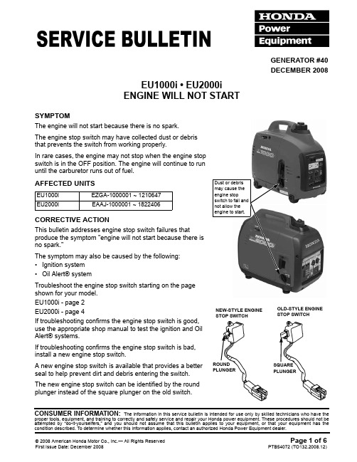
© 2008 American Honda Motor Co., Inc.— All Rights Reserved Page 1 of 6First Issue Date: December 2008PTB54072 (TO132.2008.12)CONSUMER INFORMATION: The information in this service bulletin is intended for use only by skilled technicians who have theproper tools, equipment, and training to correctly and safely service and repair your Honda power equipment. These procedures should not be attempted by “do-it-yourselfers,” and you should not assume that this bulletin applies to your equipment, or that your equipment has thecondition described. To determine whether this information applies, contact an authorized Honda Power Equipment dealer.GENERATOR #40DECEMBER 2008EU1000i • EU2000i ENGINE WILL NOT STARTSYMPTOMThe engine will not start because there is no spark.The engine stop switch may have collected dust or debris that prevents the switch from working properly.In rare cases, the engine may not stop when the engine stop switch is in the OFF position. The engine will continue to run until the carburetor runs out of fuel.AFFECTED UNITSCORRECTIVE ACTIONThis bulletin addresses engine stop switch failures thatproduce the symptom "engine will not start because there is no spark."The symptom may also be caused by the following:•Ignition system •Oil Alert® systemTroubleshoot the engine stop switch starting on the page shown for your model.EU1000i - page 2EU2000i - page 4If troubleshooting confirms the engine stop switch is good, use the appropriate shop manual to test the ignition and Oil Alert® systems.If troubleshooting confirms the engine stop switch is bad, install a new engine stop switch.A new engine stop switch is available that provides a better seal to help prevent dirt and debris entering the switch.The new engine stop switch can be identified by the round plunger instead of the square plunger on the old switch.EU1000i EZGA-1000001 ~ 1210647EU2000iEAAJ-1000001 ~ 1822406NEW-STYLE ENGINE STOP SWITCHDust or debris may cause the engine stopswitch to fail and not allow the engine to start.OLD-STYLE ENGINE STOP SWITCHSQUARE PLUNGERROUND PLUNGERPage 2 of 6© 2008 American Honda Motor Co., Inc.— All Rights ReservedPTB54072 (TO132.2008.12)GENERATOR #40DECEMBER 2008TROUBLESHOOTING PROCEDURE• EU1000i1.Turn the engine stop switch to theON position. With the generator on a level surface, pull the starter grip and check the Oil Alert® indicator.Flashing – add oil to bring the level to the upper limit. If still flashing after adding oil, proceed to step 6.Not flashing – proceed to step 2.2.Remove the maintenance cover.3.Drain the fuel tank and the carburetor float bowl into anapproved container.4.Remove the spark plug and pull the starter grip severaltimes to remove any unburned fuel from the combustion chamber.5.Insert a new spark plug in the spark plug cap andcheck for spark as shown.•Spark – the problem was the spark plug. Proceed to step 20.•No Spark – continue to step 6.6.Remove the two 5 x 20 mm screws.7.Remove the four front cover screws and the frontcover.8.Pull the control panel away from the generator.9.Disconnect the yellow oil level switch wire frombehind the control panel and recheck for spark.•Spark – the problem is the oil level switch. Replace the oil level switch following the shop manual procedure.•No Spark – proceed to step10.UPPER LIMITOIL ALERT ®INDICATOR5 x 20 mm SCREW (2)CONTROL PANELFRONT COVERFRONT COVER SCREW (4)YELLOW OIL LEVEL SWITCH WIRES© 2008 American Honda Motor Co., Inc.— All Rights ReservedPage 3 of 6PTB54072 (TO132.2008.12)GENERATOR #40DECEMBER 200810.Remove the four 5 x 16 mm washer screws and the muffler protector.11.Remove the following:•Fuel cap•Lift the neck seal and remove the 10 mm circlip •Two 6 x 100 mm screws and 6 mm washers •Two 6 x 20 mm screw-washers• 5 x 10 mm screw-washer that secures the recoil guide to the engine12. Lay the unit flat on its right side cover with the right side coverresting on a protective pad.13.Carefully separate the left side cover from the right side cover.14.Remove the fuel tube and diaphragm tube from the fuel pump.15.Disconnect the engine stop switch 2-pin connector and checkfor spark.•Spark – Proceed to step 16.•No Spark – troubleshoot the Ignition System following the shop manual procedure.16.Remove the two 3 x 16 mm self-tapping screws and theengine stop switch. Discard the engine stop switch and the harness band.17.Install the new engine stop switch and harness band. Tightenthe two 3x 16mm self-tapping screws securely. Do not over-torque. Check for spark to verify your repairs.18.Reassemble the generator.19.Add fuel and start the engine. Check for fuel leaks.20.Test the generator by performing the load bank test (see ToolOrdering Information on page 6).Maximum Output: 120V, 1.0 kVA, 8.3 Amps Rated Output: 120V, 0.9 kVA, 7.5 Amps5 x 16 mm WASHER-SCREW (4)MUFFLER PROTECTOR6 x 20 mm SCREW-WASHER (2)10 mm CIRCLIPFUEL CAPNECK SEAL6 x 100 mm SCREW (2)6 mm WASHER (2)ENGINE STOP SWITCH 2-PIN CONNECTORDIAPHRAGM TUBEFUEL TUBERECOIL GUIDE 5 x 10 mm SCREW-WASHERLEFT SIDE COVERRIGHT SIDE COVERENGINE STOP SWITCH3 x 16 mm SELF-TAPPING SCREW (2)HARNESS BANDFUEL TUBE HERE DIAPHRAGM TUBE HEREPage 4 of 6© 2008 American Honda Motor Co., Inc.— All Rights ReservedPTB54072 (TO132.2008.12)GENERATOR #40DECEMBER 2008• EU2000i1.Turn the engine stop switch tothe ON position. With the generator on a level surface, pull the starter grip. Verify the Oil Alert® indicator is not flashing.Flashing – add oil to bring the level to the upper limit. If still flashing after adding oil, troubleshoot the Oil Alert® system following the shop manual procedure.Not flashing – proceed to step 2.2.Remove the maintenance cover.3.Pinch the carburetor inlet fuel line using hosepinching pliers (available through the Honda Power Equipment Tool and Equipment program by calling (888) 424-6857) and drain the carburetor float bowl.4.Remove the spark plug and pull the starter gripseveral times to remove any unburned fuel from the combustion chamber.5.Insert a new spark plug in the spark plug cap andcheck for spark as shown.•Spark – the problem was the spark plug. Proceed to step 13.•No Spark – continue to step6.UPPER LIMITOIL ALERT ®INDICATORHOSE PINCHING PLIERS, SUN-HCP6(Commercially available)© 2008 American Honda Motor Co., Inc.— All Rights ReservedPage 5 of 6PTB54072 (TO132.2008.12)GENERATOR #40DECEMBER 20086.Locate the engine stop switch 2-pin connector(black and green wires) in the lower right side of the maintenance cover opening. Disconnectengine stop switch 2-pin connector and check for spark.•Spark – Proceed to step 7.•No Spark – troubleshoot the Ignition and Oil Alert Systems following the shop manual procedures.7.From the maintenance cover opening,disconnect the following connectors:•2-pin connector from the Eco-Throttle ® switch•8-pin connector from the ignition control module•6-pin connector from the inverter •6-pin engine harness connector8.Remove the four 6 x 15 mm special screws and slide the front cover away from the generator.9.Remove the 3 x 16 mm self-tapping screw, the 3 x 12 mm self-tapping screw, and the engine stopswitch. Discard the engine stop switch and the harness band.10.Install the new engine stop switch and harness band. Tighten the 3x 12mm and the 3x 16mm self-tapping screws securely. Do not over-torque. Check for spark to verify your repairs.11.Reassemble the generator.12.Add fuel and start the engine.13.Test the generator by performing the load bank test (see Tool Ordering Information on page 6).Maximum Output: 120V, 2.0 kVA, 16.6 Amps Rated Output: 120V, 1.6 kVA, 13.3 AmpsENGINE STOP SWITCH 2-PIN CONNECTORECO-THROTTLE 2-PIN CONNECTORIGNITION CONTROL MODULE 8-PIN CONNECTOR INVERTER6-PIN CONNECTOR ENGINE HARNESS 6-PIN CONNECTOR6 x 15 mm SPECIAL SCREW (4)FRONT COVER3 x 16 mm SELF-TAPPING SCREW3 x 12 mm SELF-TAPPING SCREWHARNESS BANDPage 6 of 6© 2008 American Honda Motor Co., Inc.— All Rights ReservedPTB54072 (TO132.2008.12)GENERATOR #40DECEMBER 2008TOOL ORDERING INFORMATIONTwo load bank test sets are available from American Honda:PARTS INFORMATIONOrder the appropriate parts through your normal parts ordering procedures.WARRANTY INFORMATIONDurationIn warrantyThe normal warranty applies.Out of warrantyAny repair performed after warranty expiration may be eligible for goodwill consideration. Contact Techline or your District Service Manager. You must request consideration and receive a decision before starting work.VIN InformationProcessingService Bulletin warranty claim submission requirements apply. After completing the Service Bulletin repair procedure, submit one warranty claim per unit with the following information:Part Number DescriptionSource06610-BCS-2612AHBCS Generator Load Bank SetAvailable through the American Honda Parts System using normal parts ordering procedures.STH-627KIT Sotcher Generator Test SetAvailable through the Honda PowerEquipment Tool and Equipment program by calling (888) 424-6857.DescriptionQty Part Number H/C Engine Stop Switch Assy.135120-ZT3-023*******Harness Band136135-ZA8-8012085512VIN Prefix Affected Serial Number RangeModelEZGA 1000001 ~ 1210647EU1000i EAAJ1000001 ~ 1822406EU2000iN Dealers:•Select Service Bulletin claim type.•Enter VIN information.•From the Service Bulletin drop down menu, select GG040 (Generator Service Bulletin #040) for appropriate model and repair.All others:Defect Code:03001Labor Operation Number:615120Flat Rate Time:0.8Failed Part:35120-ZT3-013。
本田汽油发动机使用说明书
GCV135·GCV160OWNER’S MANUALHonda Motor Co.,Ltd.200112Indicates a strong possibility of severe personal injury or death if instructions are not followed.Indicates a possibility of personal injury or equipment damage if instructions are not followed.Indicates that equipment or property damage can are not followed.The Honda engine is designed to give safe and dependable service if operated according to instructions.Read and understand the Owner’s Manual before operating the engine.Failure to do so could result in personal injury or equipment damage.Thank you for purchasing a Honda engine.This manual covers the operation and maintenance of your engine:All information in this publication is based on the latest product information available at the time of printing.Honda Motor Co.,Ltd.reserves the right to make changes at any time without notice and without incurring any obligation.No part of this publication may be reproduced without written permission.This manual should be considered a permanent part of the engine and should remain with it if it is resold.Pay special attention to statements preceded by the following words:Gives helpful information.If a problem should arise,or if you have any questions about your engine,consult an authorized Honda dealer.GCV135·GCV1603SAFETY INSTRUCTIONSTo ensure safe operation Always make a pre-operation inspection (page )before you start the engine.You may prevent an accident or equipment damage.To prevent fire hazards and to provide adequate ventilation,keep the engine at least 1meter (3feet)away from buildings and other equipment during operation.Do not place flammable objects close to the engine.Children and pets must be kept away from the area of operation due to a possibility of burns from hot engine components or injury from any equipment the engine may be used to operate.Know how to stop the engine quickly,and understand the operation of all controls.Never permit anyone to operate the engine without proper instructions.Do not place flammable objects such as gasoline,matches,etc.,close to the engine while it is running.Refuel in a well-ventilated area with the engine stopped.Gasoline is highly flammable and explosive under certain conditions.Do not overfill the fuel tank.There should be no fuel in the filler neck.Make sure that the filler cap is closed securely.64Safety InstructionSAFETY INDICATION LOCATION If any fuel is spilled,clean it up completely and allow petroleum vapours to dissipate before starting the engine.To ensure safe operation Do not smoke or allow flames or sparks where the engine is refueled or where gasoline is stored.Exhaust gas contains poisonous carbon monoxide.Avoid inhalation of exhaust gases.Never run the engine in a closed garage or confined area.Do not place anything on the engine,as it may create a fire hazard.A spark arrester is available as an optional part for this engine.It is illegal in some areas to operate an engine without a spark arrester.Check local laws and regulations before operating.The muffler becomes very hot during operation and remains hot for a while after stopping the engine.Be careful not to touch the muffler while it is hot.To avoid severe burns or fire hazards,let the engine cool before transporting it or storing it indoors.Place the engine on a stable surface.Do not tilt the engine more than 15°from horizontal.Operating at excessive angles may result in fuel spillage.This indication warns you of potential hazards that can cause serious injury.Read it carefully.5COMPONENT IDENTIFICATIONOIL PLUGSTARTER TANKAIR6PRE-OPERATION CHECKEngine oil levelBe sure to check the engine on a level surface with the engine stopped.Running the engine with insufficient oil can cause serious engine damage.Using nondetergent oil or 2-stroke engine oil could shorten the engine’s service life.1.LIMITFILLER CAP/SAE Viscosity Grades AMBIENT TEMPERATURE If the level is low,add the recommended oil to the upper limit on the dipstick.Remove the oil filler cap and wipe the dipstick clean.Insert the dipstick into the oil filler neck,but do not screw it e Honda 4-stroke,or an equivalent high detergent,premium quality mo-tor oil certified to meet or exceed U.S.automobile manufacturer’s require-ments for service classification SG,SH.Motor oils classified SG,SH will showthis designation on the container.SAE 10W-30is recommended for gen-eral,all temperature use.If single vis-cosity oil is used,select the appropri-ate viscosity for the average tempera-ture in your area.1.2.3.Air cleaner2.Never run the engine without the air cleaner.Rapid engine wear will result.Remove the air cleaner cover and check the cleaner for dirt or obstruction of the element(page19).78FuelGasoline is extremely flammable and is explosive under certain conditions.Refuel in a well-ventilated area with the engine stopped.Do not smoke or allow flames or sparks in the area where the engine is refueled or where gasoline is stored.Do not overfill the fuel tank (there should be no fuel in the filler neck).After refueling,make sure the tank cap is closed properly and securely.Be careful not to spill fuel when refueling.Spilled fuel or fuel vapor may ignite.If any fuel is spilled,make sure the area is dry before starting the engine.Avoid repeated or prolonged contact with skin or breathing of vapor.KEEP OUT OF REACH OF CHILDREN.Fuel tank capacity:3.FILLER Use automotive gasoline (Unleaded or lowleaded is preferred to minimize combustion chamber deposits).FOR NEW SOUTH WALES ONLY:Use unleaded fuel only.Never use an oil/gasoline mixture or dirty gasoline.Avoid getting dirt,dust or water in the fuel tank.1.1(0.29US gal ,0.24Imp gal)0.9(0.24US gal ,0.20Imp gal)GCV135:GCV160:GASOLINES CONTAINING ALCOHOLIf you decide to use a gasoline containing alcohol(gasohol),be sure it’s octane rating is at least as high as that recommended by Honda.There are two types of‘‘gasohol’’:one containing ethanol, and the other containing methanol.Do not use gasohol that contains more than10%ethanol.Do not use gasoline containing methanol(methyl or wood alcohol)that does not also contain cosolvents and corrosion inhibitors for methanol.Never use gasoline containing more than5%methanol,even if it has cosolvents and corrosion inhibitors.Fuel system damage or engine performance problems resulting from the use of fuels that contain alcohol is not covered under the warranty.Honda cannot endorse the use of fuels containing methanol since evidence of their suitability is as yet incomplete. Before buying fuel from an unfamiliar station,try to find out if the fuel contains alcohol,if it does,confirm the type and percentage of alcohol used.If you notice any undesirable operating symptoms while using a gasoline that contains alcohol,or one that you think contains alcohol,switch to a gasoline that you know does not contain alcohol.910STARTING THE ENGINEFUEL LEVERDo not use the choke if the engine is warm or the air temperature is high.Turn the fuel valve to the ON position.Move the control lever to the CHOKE position.1.2.11Do not allow the starter grip to snap back against the engine.Return it gently to prevent damage to the starter.FLYWHEEL Pull the starter grip lightly until resistance is felt,then pull briskly.The engine switch,which is linked with the flywheel brake lever,is turned on when the flywheel brake lever is moved to the RELEASED position.Move the flywheel brake lever to the RELEASED position.3.4.With FLYWHEEL BRAKE LEVER type only:12SLOW FASTWhen engine warms up,move the control lever to FAST or SLOW.5.High altitude operationAt high altitude,the standard carburetor air-fuel mixture will be ex-cessively rich.Performance will decrease,and fuel consumption will increase.High altitude performance can be improved by installing a smaller diameter main fuel jet in the carburetor and readjusting the pilot screw.If you always operate the engine at altitudes higher than 1,830m(6,000feet)above sea level,have your authorized Honda dealer perform these carburetor modifications.Even with suitable carburetor jetting,engine horsepower will decrease approximately3.5%for each305m(1,000feet)increase in altitude.The affect of altitude on horsepower will be greater than this if no carburetor modification is made.Operation of the engine at an altitude lower than the carburetor is jetted for may result in reduced performance,overheating,and serious engine damage caused by an excessively lean air/fuel mixture.1314STOPPING THE ENGINECONTROL LEVERMove the control lever to the SLOW position.The engine switch,which is linked with the flywheel brake lever,is turned off when the flywheel brake lever is moved to the ENGAGED position.Return the flywheel brake lever to the ENGAGED position.1.2.With FLYWHEEL BRAKE LEVER type:15FUEL Turn the fuel valve to the OFF position.Move the control lever to the STOP position.The engine switch,which is linked with the control lever,is turned off when the control lever is moved to the STOP position.3.4.Without FLYWHEEL BRAKE LEVER type:MAINTENANCEShut off the engine before performing any maintenance.To prevent accidental start-up,disconnect the spark plug cap. The engine should be serviced by an authorized Honda dealer unless the owner has proper tools and service data and feels he is mechanically qualified.Use only genuine Honda parts or their equivalent.The use of replacement parts which are not of equivalent quality may damage the engine.Periodic inspection and adjustment of the Honda engine is essential if high level performance is to be maintained.Regular maintenance will also ensure a long service life.The required service intervals and the kind of maintenance to be performed are described on the following table.1617Maintenance ScheduleREGULAR SERVICE PERIOD (4)Every 2years (Replace if necessary)(3)CheckChangeCheckCleanReplaceCheckCheck-AdjustReplaceCleanCheck-AdjustCleanCheck-AdjustCleanCheck Engine oil Air cleaner Flywheel brake pad (applicable types)Spark plug Spark arrester (optional part)Idle speed Fuel tank and filter Valve clearance Combustion chamber Fuel tube Service more frequently when used in dusty areas.Change engine oil every 25hours when used under heavy load or in high ambient temperature.These items should be serviced by an authorized Honda dealer,unless the owner has theproper tools and is mechanically proficient.See the Honda Shop Manual.For commercial use,log hours of operation to determine proper maintenance intervals.ITEMPerform at every indicated month oroperating hours interval,whichevercomes first.(1):(2):(3):(4):Each use First month or 5hrs.Every 3or 25hrs.Every year or Every 6or 50hrs.Every Every or (1)(2)(3)(3)(3)months 100hrs.months 150hrs.2years 250hrs.18Oil changeENGINE OIL CAPACITY:1.OIL Drain the oil while the engine is still warm to assure rapid and complete draining.Please dispose of used motor oil in a manner that is compatible with the environment.We suggest you take it in a sealed container to your local service station for reclamation.Do not throw it in the trash,pour it on the ground,or down a drain.Wash your hands with soap and water after handling used oil.0.55(0.58US qt ,0.48Imp qt)Install the oil filler cap.Refill with the recommended oil and check the oil level (see page ).Remove the oil filler cap and drain the oil into the oil container by inclining the engine toward the oil filler neck.Turn the fuel valve to the OFF position (see page ).1.2.3.4.61519Air cleaner serviceNever run the engine without the air cleaner.Rapid engine wear will result.Never use gasoline or low flash point solvents for cleaning the air cleaner element.A fire or explosion could result.2.A dirty air cleaner will restrict air flow to the carburetor.To prevent carburetor malfunction,service the air cleaner regularly.Service more frequently when operating the engine in extremely dusty areas.Remove the air cleaner cover by unhooking the two upper tabs on the top of the air cleaner cover and the two lower tabs.Remove the element.Carefully check the element for holes or tears and replace if damaged.1.2.20Tap the element lightly several times on a hard surface to remove excess dirt,or blow compressed air through the filter from the inside out.Never try to brush the dirt off;brushing will force dirt into the fibers.Replace the element if it is excessively dirty.Install the element and air cleaner cover.3.4.21Flywheel brake inspection 3.RECOIL STARTERSHOETANKCheck the brake shoe thickness.If it is less than 3mm (0.12in),replace it with new one.Remove the recoil starter by removing the three 6mm nuts.Remove the fuel tank taking care not to disconnect the fuel tube from the fuel tank and fuel valve,and keeping the fuel tank to a level.Install the fuel tank and recoil starter,and tighten the three 6mm nuts securely.1.2.3.4.(applicable types)22Spark plug serviceRecommended spark plug:Never use a spark plug of incorrect heat range.If the engine has been running,the muffler will be very hot.Be careful not to touch the muffler.4.BPR6ES (NGK)To ensure proper engine operation,the spark plug must be properly gapped and free of deposits.Remove the spark plug cap and use a spark plug wrench to remove each spark plug.1.230.700.80mm(0.0280.031in)Visually inspect the spark plug.Discard the spark plug if there is apparent wear,or if the insulator is cracked or chipped.Clean the spark plug with a wire brush if it is to be reused.0.700.80mm (0.0280.031in)Measure the plug gap with a feeler gauge.Correct as necessary by bending the side electrode.The gap should be:2.3.24The spark plug must be securely tightened.An improperly tightened spark plug can become very hot and may damage the engine.Check that the spark plug washer is in good condition and thread the spark plug in by hand to prevent cross-threading.When installing a new spark plug,tighten 1/2turn after the spark plug seats to compress the washer.When reinstalling a used spark plug,tighten 1/81/4turn after the spark plug seats to compress the washer.After the spark plug is seated,tighten with a spark plug wrench to compress the washer.5.4.25Spark arrester maintenance (optional part)If the engine has been running,the muffler will be very hot.Allow it to cool before proceeding.The spark arrester must be serviced every 100hours to maintain its efficiency.5.6Remove the muffler protector by removing the three 6mm bolts.Remove the spark arrester from the muffler by removing the two screws.(Taking care not to damage the wire mesh.)Check for carbon deposits around the exhaust port and the spark arrester,and clean if necessary.1.2.26Be careful not to damage the spark arrester screen.Use a brush to remove carbon deposits from the spark arrester screen.The spark arrester must be free of breaks and holes.Replace,if necessary.Install the spark arrester and the muffler in the reverse order of disassembly.3.4.27TRANSPORTING/STORAGEWhen transporting the engine,turn the fuel valve OFF and keep the engine level to prevent fuel spillage.Fuel vapor or spilled fuel may ignite.Gasoline is extremely flammable and is explosive under certain conditions.Do not smoke or allow flames or sparks in the area.Before storing the unit for an extended period;Be sure the storage area is free of excessive humidity and dust.Drain the fuel tank and carburetor into a suitable gasoline container:Turn the fuel valve to the OFF position.Remove the carburetor drain bolt and drain the carburetor.Turn the fuel valve to the ON position and drain the fuel in the fuel tank into the container.Retighten the carburetor drain bolt so that the float chamber and washer cannot be warped,and turn the fuel valve to the OFF position.1.2.A.B.C.D.28Change the engine oil (page 18).Pull the starter rope slowly until resistance is felt.This closes the valves,and protects them from dust and corrosion.Coat areas that may rust with a light film of oil.Cover the engine and store it on a level surface in a dry,dust free area.5.3.4.29TROUBLESHOOTINGIf any fuel is spilled,make sure the area is dry before testing the spark plug or starting the engine.Fuel vapor or spilled fuel may ignite.When the engine will not start:Is the fuel valve ON?Is there fuel in the fuel tank?Is gasoline reaching the carburetor?To check,loosen the drain bolt with the fuel valve ON.1.2.3.30Remove the spark plug cap.Clean any dirt from around the spark plug base,then remove the spark plug.Install the spark plug in the plug cap.Grounding the side electrode to any engine ground,pull the recoil starter to see if sparks jump across the gap.If there is no spark,replace the plug.If OK,reinstall the spark plug and try to start the engine again according to the isntructions.If the engine still does not start,take the engine to an authorized Honda dealer.Is the control lever positioned properly (page 10)?Is the flywheel brake lever positioned to the RELEASED position (page 11)?(applicable types)Is there a spark at the spark plug?7.4.5.6.d.a.b.c.SPECIFICATIONSSpecifications may vary according to the types,and are subject to change without notice.31Specifications may vary according to the types,and are subject to change without notice.32。
本田汽油发电机说明书

一、安全注意事项1、请勿在室内使用!2、请勿在潮湿的环境使用!3、请勿连接到家庭电路。
4、当水银灯(放电管)及或其它灯熄灭时,待冷却后再打开。
5、请远离易燃物!加油时:关闭发动机!请勿将油溢出!请勿吸烟!二、操作前检查注:每次使用前,请查看发动机周围和底部是否有机油或汽油泄漏迹象。
机油位1、检查机油位。
(建议使用适应于所有气温的机油型号SAE 10W-30)2、如果油位低,请加机油至注入口颈部的低位界线。
燃油位1、检查汽油位。
2、若汽油位低,加汽油至上部油位。
3、千万不要使用混合汽油或不洁汽油。
空气滤清器1.卸下保养罩,再卸下空气滤清器罩。
2.检查空气滤清器滤芯,确认其是清洁的而且处于良好状态。
清洗:清洁滤芯时挤压并吸干水分。
不要扭绞,在机油(4冲程机油)中浸一下,挤压使机油排出,不要扭绞。
3.重新安装空气滤清器滤芯,空气滤清器罩和保养罩。
三、启动发动机1.转动燃油注入口盖通气手柄,顺时针方向完全调至ON位置。
注:当搬运发电机时,应将燃油注入口盖通气手柄调至OFF位置。
2.将发动机开关调至“打开(ON)”位置。
3.轻轻拉起启动抓手直至感到阻力为止,然后用力拉起。
4.把阻风门杆移到打开(OPEN)位置。
5.把阻风门杆移到关闭(CLOSED)位置,发动机暖机时,不得使用阻气门。
机油警告系统机油警告系统用于防止曲轴箱的油量不足所致发动机故障。
若机油警告系统关闭发动机,当操作启动装置时,机油警告指示灯将闪烁,发动机将不运转。
此时,应补充发动机机油。
四、发电机组的使用如下所示,使发电机组在机械和电气方面均保持最佳状态。
为避免因装置故障发生电击,应将发电机组接地。
生态节气门打开生态节气门开关后,通过自动调节发动机的速度来调整到所需的发电机功率。
关闭生态节气门开关后,发动机按照恒定速度运转,保持额定功率。
输出和超载指示灯正常操作情况下,输出指示灯(绿色)保持常亮。
而且,输出指示灯具有简易的计时器功能。
启动发动机时,指示灯根据发电机的累计工作时间如下闪烁:*不闪烁: 0—100小时 *闪烁3次:300—400小时*闪烁1次: 100—200小时 *闪烁4次:400—500小时*闪烁2次: 200—300小时 *闪烁5次:500小时以上如果发电机超载,或如果连接设备发生短路,超载指示灯(红色)将点亮,连接设备的电流将被切断,并且输出指示灯(绿色)将熄灭。
汽油发电机详细说明

汽油发电机详细说明基本结构藤岛发电机通常由定子、转子、端盖及轴承等部件构成。
定子由定子铁芯、线包绕组、机座以及固定这些部分的其他结构件组成。
转子由转子铁芯(或磁极、磁扼)绕组、护环、中心环、滑环、风扇及转轴等部件组成。
由轴承及端盖将藤岛发电机的定子,转子连接组装起来,使转子能在定子中旋转,做切割磁力线的运动,从而产生感应电势,通过接线端子引出,接在回路中,便产生了电流。
工作原理藤岛汽油发电机发动机是将化学能转化为机械能的机器,它的转化过程实际上就是工作循环的过程,简单来说就是是通过燃烧气缸内的燃料,产生动能,驱动发动机气缸内的活塞往复的运动,由此带动连在活塞上的连杆和与连杆相连的曲柄,围绕曲轴中心作往复的圆周运动,而输出动力的。
现在,我们分析一下这个过程:一个工作循环包括有四个活塞行程(所谓活塞行程就是指活塞由上止点到下止点之间的距离的过程):进气行程、压缩行程、膨胀行程(作功行程)和排气行程。
进气行程在这个过程中,发动机的进气门开启,排气门关闭。
随着活塞从上止点向下止点移动,活塞上方的气缸容积增大,从而使气缸内的压力将到大气压力以下,即在气缸内造成真空吸力,这样空气便经由进气管道和进气门被吸入气缸,同时喷油嘴喷出雾化的汽油与空气充分混合。
在进气终了时,气缸内的气体压力约为0.075-0.09MPa。
而此时气缸内的可燃混合气的温度已经升高到370-400K。
压缩行程为使吸入气缸的可燃混合气能迅速燃烧,以产生较大的压力,从而使发动机发出较大功率,必须在燃烧前将可燃混合气压缩,使其容积缩小、密度加大、温度升高,即需要有压缩过程。
在这个过程中,进、排气门全部关闭,曲轴推动活塞由下止点向上止点移动一个行程,即压缩行程。
此时混合气压力会增加到0.6-1.2MPa,温度可达600-700K。
在这个行程中有个很重要的概念,就是压缩比。
所谓压缩比,就是压缩前气缸中气体的最大容积与压缩后的最小容积之比。
一般压缩比越大,在压缩终了时混合气的压力和温度便愈高,燃烧速度也愈快,因而发动机发出的功率愈大,经济性愈好。
本田发动机操作说明书

1 (1) (2) (2) (3)3 (4)4 (4) (4) (5) (6) (6) (6) (6) (7) (7) (7) (8) (8) (8) (8) (9) (9) (9)火花塞 (10)火花避雷器 (10)有用的提示和建议 (11)存储发动机 (11)运送 (12)注意意外问题 (12)技术信息 (13)序列号位置 (13)遥控器连接 (13)高海拔操作时的化油器改装 (13)规格 (14)调整规格 (14)快速参考信息 (14)线路图 (14)安全信息•理解所有控制的操作并学习在紧急情况下如何快速停止发动机。
操作设备前确保操作员接收足够的指示。
•不要让儿童操作发动机。
让儿童和宠物远离操作区域。
•发动机废气包括有毒的一氧化碳。
不要在通风不良时运行发动机,也不要在室内运行发动机。
•发动机和废气在运行时变得很烫。
操作时,使发动机远离建筑物和其他设备至少 1 米远。
远离易燃材料,并且在发动机运行时不要在发动机上放置任何物品。
•此发动机设计用于通用机械。
不要试图用于其他目的,如起动汽车或摩托车。
安全标签位置此标签提醒您可引起严重伤害的潜在危险。
请仔细阅读。
如果标签脱落或无法阅读,请联系 Honda 维修经销商进行更换。
部件和控制位置特性离心离合器(适用类型)当发动机转速增加至约 2,900转/分以上时,离心离合器自动接合并传输电力。
怠速时,离合器分离。
未将发动机安装在配有离心离合器鼓和壳体的设备上时,不要运行发动机,否则离心力会使离合器蹄块碰到并损坏发动机箱。
燃油箱通风口燃油箱盖配有一个通风口旋钮以密封燃油箱。
逆时针转动燃油箱盖通风口旋钮至少 2 或 3 圈打开燃油箱通风口。
操作前检查发动机是否已准备妥当?出于安全考虑,务必遵守环境条例,并尽可能延长设备的使用寿命,操作发动机前花一些时间检查工作条件是很重要的。
务必注意发现的问题,或在操作发动机前请维修经销商进行修理。
开始操作前检查前,确保发动机水平且设备上的发动机开关置于 OFF 位置。
发电机使用说明书(中文)
1.概说1.1 发电机为隐极式同步发电机,由汽轮机驱动。
1.2 发电机采用静止可控硅励磁。
1.3发电机采用封闭循环的通风系统,有空气冷却器。
1.4 发电机旋转方向从汽轮机端看为顺时针。
1.5 发电机的使用环境条件为:海拔不超过1000m ;冷却气体温度不超过+C o 40; 相对湿度不大于75%;不受昆虫,爬虫及腐蚀性气体侵蚀的室内。
1.6 空气冷却器的进水温度不大于+C o 33。
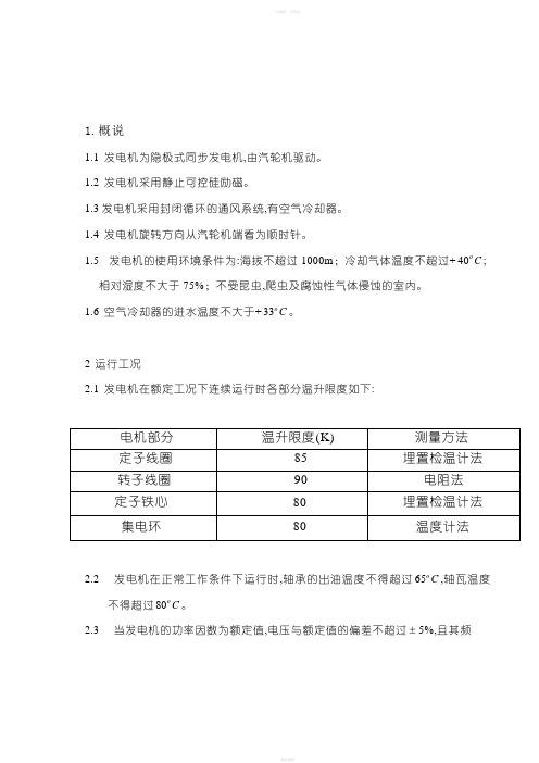
2 运行工况2.1 发电机在额定工况下连续运行时各部分温升限度如下:2.2 发电机在正常工作条件下运行时,轴承的出油温度不得超过C o 65,轴瓦温度不得超过C o 80。
2.3 当发电机的功率因数为额定值,电压与额定值的偏差不超过±5%,且其频率与额定值偏差不超过±2%时,其出力保持不变。
2.4 发电机在每相电流不超过额定值,且负序分量与额定电流之比不超过10%时,允许其在三相不平衡负载下连续运行。
2.5 发电机在一般情况下,不保证过载运转。
3 结构简介3.1 发电机机座由钢板焊成,吊攀位于定子两侧面的中部。
为防止油污及灰尘进入电机内部,在端盖上设有高压气密封装置。
3.2 发电机定子铁心是由经涂漆处理过的0.5mm高硅扇形片套于鸽尾支持筋上叠压而成,全长分成若干段,形成若干径向风道,铁心用压圈压紧。
3.3 发电机定子线圈由双玻扁铜线制成。
采用全粉云母F级绝缘。
直线部分与端部均采用模压,端部作成篮式渐伸线结构。
经三个端箍成一整体,并通过环氧玻璃布板支架固定在机座两端。
定子线圈对半组成,端部连接采用银焊。
定子在引出线端有6根出线铜排。
3.4 发电机转子用整体优质合金钢锻成,冷却方式为空气表面冷却。
在转子大齿上开有通风槽,通风槽楔上留有风孔,以改善转子表面散热效果,护环上开有通风孔以便更有效地冷却转子线圈的端部。
3.5 转子线圈是用裸铜线绕成,其匝间绝缘用绝缘垫条或半叠包以绝缘带。
转子线槽槽楔采用非磁性材料制成,以减少漏磁。
HONDA 发动机EB10000发电机说明书

Honda Power EquipmentEB10000 Generator AC Receptacle SelectionIntroductionThe EB10000 generator has two different model types: AH and AH1.To determine which type of generator you have, locate the frameserial number on your generator, and then refer to the table below.Power Circuits The EB10000 generator is equipped with two powercircuits, A and B. The circuits act like two separate generators, with each circuit supplying up to 41.6 amps to specific receptacles. Neither power circuit can supplypower to the other power circuit’s receptacles.Therefore, it is important to balance the load on both power circuits.Power circuit A can supply up to 41.6 amps at 120 voltsto receptacles 1A, 2A and 4. Power circuit B can supplyup to 41.6 amps at 120 volts to receptacles 1B, 2B, 3and 5.If you need 240 volt power, receptacle 1 (the combination of terminal 1A and terminal 1B) can provide up to 41.6 amps at 240 volts (this receptacle is rated at 50 amps). Receptacle 2 (2A and 2B) can provide up to 30 amps at 240 volts (the receptacle is only rated at 30 amps).You can use any combination of receptacles to power 120 volt and 240 volt loads as long as the current required of each power circuit does not exceed 41.6 amps.Control PanelAH TypeThe control panel has five receptacles:•Receptacle 1 is a 50A-120V/240V locking receptacle thatcan supply up to 41.6 amps at 240V. Half of its current issupplied by power circuit A (terminal 1A) and half issupplied by power circuit B (terminal 1B).•Receptacle 2 is a 30A-120V/240V (NMEA L14-30)receptacle that can supply up to 30 amps at 240V. Half ofits current is supplied by power circuit A (terminal 2A) andhalf is supplied by power circuit B (terminal 2B).•Receptacle 3 is 30A-120V (NMEA L5-30) receptacle that can supply up to 30 amps from power circuit B.•Receptacle 4* has two 20A-120V outlets that can supply up to 20 amps from power circuit A.•Receptacle 5* has two 20A-120V outlets that can supply up to 20 amps from power circuit B.*Each outlet of the receptacle has a maximum output of 20 amps. For example, if you are using 20 amps through the top outlet, the bottom outlet can also supply 20 amps. TypeFrame Serial Number Range AH EBVC-1000001 ~ 1004169AH1EBVC-1004170 ~ subsequent SERIAL NUMBER1A 2A 31B 2B 5RECEPTACLES 421Honda Power EquipmentAH1 TypeThe control panel has five receptacles:•Receptacle 1 is a 50A-120V/240V locking receptacle thatcan supply up to 41.6 amps at 240V. Half of its current issupplied by power circuit A (terminal 1A) and half issupplied by power circuit B (terminal 1B).•Receptacle 2 is a 30A-120V/240V (NMEA L14-30)receptacle that can supply up to 30 amps at 240V. Half ofits current is supplied by power circuit A (terminal 2A) andhalf is supplied by power circuit B (terminal 2B).•Receptacle 3 is 30A-120V (NMEA L5-30) receptacle that can supply up to 30 amps from power circuit B.•Receptacle 4* is a GFCI duplex outlet that can supply up to 20 amps from power circuit A.•Receptacle 5* is a GFCI duplex outlet that can supply up to 20 amps from power circuit B.*Each duplex receptacle has a maximum output of 20 amps. For example, if you are using 12 amps through the top outlet, the bottom outlet can only supply 8 amps.OverloadingThe rated power of this generator is 9.0kVA; maximum power is 10.0kVA. Never exceed the maximum power rating of the generator. Power levels between rated and maximum may be used for no more than 30minutes. For continuous operation, do not exceed the rated power.1A 2A 31B 2B 5RECEPTACLES 421。