宜准L002电波表中英文说明书
FISICA 3B SCIENTIFIC 微伏特表 用户手册说明书
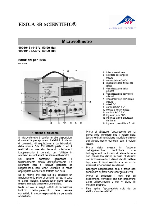
FISICA 3B SCIENTIFIC®11001015 (115 V, 50/60 Hz) 1001016 (230 V, 50/60 Hz)Istruzioni per l'uso09/15 SP1 interruttore di rete2 selettore del range dimisura3 commutatore CA/CC4 regolatore della frequenzalimite5 visualizzazione dellapolarità6 visualizzazione del valoremisurato7 visualizzazione dell’unità dimisura 8 offset CC9 uscita CA/CC 1 V10 messa a terra / massa 11 uscita CA/CC 2 V 12 ingresso jack BNC13 ingresso jack di sicurezzada 4 mm14 ingresso presa DIN a 5 poliIl microvoltmetro è conforme alle disposizioni di sicurezza per apparecchi elettrici di misura, di comando, di regolazione e da laboratorio della norma DIN EN 61010 parte 1 ed è realizzato in base alla classe di protezione I. L’apparecchio è pensato per l’utilizzo in ambienti asciutti adatti per strumenti elettrici. Un utilizzo conforme garantisce il funzionamento sicuro dell’apparecchio. La sicurezza non è tuttavia garantita se l’apparecchio non viene utilizzato in modo appropriato o non viene trattato con cura.Se si ritiene che non sia più possibile un funzionamento privo di pericoli (ad es. in caso di danni visibili), l’apparecchio deve essere messo immediatamente fuori servizio.Nelle scuole e negli istituti di formazione l’utilizzo dell’apparec chio deve essere controllato in modo responsabile da personale addestrato.∙Prima di utilizzare l’apparecchio per la prima volta verificare che il valore della tensione di alimentazione riportato sul retro dell’alloggiamento coincida con il valore locale.∙Prima della messa in funzione dell’apparecchio controllare che l’alloggiamento e il cavo di alimentazione non presentino danni; in caso di disturbi nel funzionamento o danni visibili mettere l’apparecchio fuori servizio e al sicuro da eventuali azionamenti accidentali.∙ Collegare l'apparecchio solo a prese con conduttore di protezione collegato a terra. ∙Prima di collegare i cavi per gli esperimenti, verificare che non presentino danni all’isolamento e non vi siano fili metallici scoperti.∙Fare aprire l’appa recchio solo da un elettricista specializzato.3B Scientific GmbH ▪ Rudorffweg 8 ▪ 21031 Hamburgo ▪ Germania ▪ Con riserva di modifiche tecniche © Copyright 2015 3B Scientific GmbHL'apparecchio consente di misurare e amplificare tensioni continue e alternate estremamente piccole (max. 2 V), come ad es. tensioni a induzione, termiche e ottiche. La misurazione viene indicata su un display a LED. Inoltre è possibile collegare anche un misuratore dimostrativo. Il segnale di misura viene alimentato mediante un jack BNC o un jack di sicurezza da 4 mm. Un commutatore consente di eseguire misurazioni in CA o CC. Nell'ingresso di misura è possibile collegare un filtro per il livellamento del segnale o per la limitazione superiore della frequenza di misura. Si possono impostare 4 frequenze fisse. Il filtro consente di ridurre le tensioni di disturbo durante le misurazioni di tensioni continue e alternate. Una presa DIN supplementare permette di collegare facilmente delle sonde di Hall.L’apparecchio 1001015 è progettato per una tensione di rete di 115 V (±10 %), 1001016 per 230 V (±10 %).Tensione di uscita: 0 – ±2 V Corrente di uscita:max. 1 mAResistenza d'entrata: range CC: 100 k Ω range CA: 900 k ΩVisualizzazione misura: display LED a 3,5 cifre Collegamenti in ingresso: 2 jack di sicurezzada 4 mm ,jack BNC presa DIN a 5 poliCollegamenti in uscita: 3 jack di sicurezza da4 mmTensione di alimentazione: vedere sul retrodell’alloggiamentoFusibile primario: vedere sul retrodell’alloggiamentoDimensioni: 235 × 250 × 180 mm³ Peso: ca. 3,3 kg4.1 Funzionamento come misuratore CC ∙ Applicare la tensione di esercizio. ∙ Impostare il commutatore su CC.∙Impostare il range di misura (200 μV –200 mV).∙ Mettere in cortocircuito l’ingresso e regolare il punto zero con l’offset CC.∙ Rimuovere il cortocircuito e collegare ilcarico all’ingresso.4.2 Funzionamento come misuratore CA ∙ Applicare la tensione di esercizio. ∙ Impostare il commutatore su CA.∙ Impostare il range di misura (200 μV –200 mV).∙Collegare il carico all’ingresso.4.3 Funzionamento come amplificatore dimisura CC∙ Applicare la tensione di esercizio. ∙ Impostare il commutatore su CC.∙ Impostare il range di misura (200 μV –200 mV).∙ Mettere i n cortocircuito l’ingresso e regolare il punto zero con l’offset CC.∙Rimuovere il cortocircuito e collegare il misuratore dimostrativo (visualizzazione analogica, range di misura fino a 2 V) all’uscita.∙Collegare il carico all’ingresso.4.4 Funzionamento come amplificatore dimisura CA∙ Applicare la tensione di esercizio. ∙ Impostare il commutatore su CA.∙ Impostare il range di misura (200 μV –200 mV).∙Collegare il misuratore dimostrativo (visualizzazione analogica, range di misura fino a 2 V) all’uscita.∙Collegare il carico all’ingresso.∙ Smaltire l'imballo presso i centri di raccolta e riciclaggio locali. ∙Non gettare l'apparecchio nei rifiuti domestici. Perlo smaltimento delle appare- cchiature elettriche, rispet- tare le disposizioni vigenti a livello locale.∙Non gettare le batterie esaurite nei rifiuti domestici. Rispettare le disposizioni legali locali (D: BattG; EU: 2006/66/EG).。
常用仪器仪表的使用说明

2、实验台面: 、实验台面: 实验台面上有通用实验底板,实验时根据电路的特点合理选择位置插入元件盒, 实验台面上有通用实验底板,实验时根据电路的特点合理选择位置插入元件盒,元 件盒插入拨出要轻、 大的元件盒需用双手垂直插拨。 件盒插入拨出要轻、慢,大的元件盒需用双手垂直插拨。 3、电路插拼方法 、 选择一个电路图,根据电路的内容,在元件储存板上取出电路图中所需的元件盒, 选择一个电路图,根据电路的内容,在元件储存板上取出电路图中所需的元件盒, 在桌面上应垂直插拨,先插大面积的插座,后插小型插座, 在桌面上应垂直插拨,先插大面积的插座,后插小型插座,再用连接块及连接线连接成 插拼好后校对电路图二次。 图,插拼好后校对电路图二次。 4、实验结束后元件盒及元件储存板应放回原处,以方便下次再用 、实验结束后元件盒及元件储存板应放回原处,
有信号时无须调节器节电平即能获得稳定波形提示23触发指示trigd在触发同步时指示灯亮24水平扫速开关secdiv调节扫描速度25水平微调var连续调节扫描速度顺时针旋足为校正位置26内触发源intsource选择ch1ch2电源或交替触发27触发选择选择内int或ext触发28接地gnd与机壳相联的接地端29外触输入ext外触发输入插座30xy方式开关ch1选择xy工作方式31扫描扩展开关按下时扫速扩展10倍32交替扫描扩展开关按下时屏幕上同时提示扩展后未被和未被扩展的波形33扫描分离tracsep交替扫描扩展时调节扩展和未扩展波形的相对距离34释抑控制holdoff改变扫描休止时间同步多调期复杂波形35外监频输出监视示波器提示某一通道波形的频率36电源插座及保险丝座220v电源插座保险丝05a在后面板下pos900022010控制件名称作用位置控制件名称作用位置亮度inten1居中触发方式15峰值自动聚焦focus2位移ch1ch2x居中居中扫描速度secdiv24极性slope2105ms垂直方式mode9ch1触发源27intvoltsdiv111210mv内触发源26ch1微调var1312校正位置耦合方式1516ac10ch1ch122ch2ch222图d2校正信号波形modech1ch2modealtchopmodeaddch2inv10ch1ch2invch1ch2dcacgndch1x3027extintch1vertmodech1acautonorachopaddch1ch22sdiv05sdiv1010103110secdiv1102sdiv2sdiv11020nsdiv3233norm20hzauto20hztvch2ch2inv10leveltrigdholdoff10m16pf1m70pf400vppkcacpp1dhzelectronicsworkbenchewbe1ewbcomponeቤተ መጻሕፍቲ ባይዱtpropertieslabelreferenceidvaluemodelfaultreferenceidfaultopenshortleakagenonedeletecircuitschematicoptiongridfontsewb109e9settinge10e10expandtimebasedc1011e11acmagnitudephaseverticalhorizontalloglinew
LMI02-V1 0中文
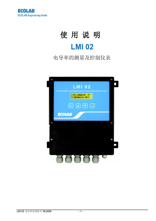
使用说明LMI 02电导率的测量及控制仪表1 概述本手册包含了LMI02的功能、操作、结构以及维修方面的各种信息。
LMI02是基于电磁感应测量原理的电导率测量和控制设备。
1.1 技术支持与维修维修和技术服务一定要在另一本手册的帮助下由授权过合格的人员来操作。
警告在维修和技术服务时一定要穿戴合适安全的衣服和护目镜。
1.2 运输过程中的损坏在打开包装时如果您发现设备在运输过程中损坏,请不要安装此设备。
1.3 保修只有在以下情况下制造商才能保证设备的安全使用和计量准确。
组装、连接、安装、技术支持、维修必须由授权的工作人员负责。
- 计量原件的使用必须遵循技术手册的相关说明。
- 在维修过程中必须使用原厂配件。
- 必须使用认可的化学品。
另外,在艺康公司可以获得一般的质量保证和服务。
1.4 联系方式/制造商ECOLAB-工程公司Raiffeisenstraße7D-83313Siegsdorf,GermanyTelephone(+49)8662 / 610Fax(+49)8662 / 61235eMail:engineering-mailbox@警告2 安全2.1 概况本仪表的制造和测试符合工业标准DIN EN 61010-1:2004-01。
为保证安全,操作人员必须严格遵循本手册的相关安全规定。
设备发生故障可参照本手册第10章查找排除。
2.2 标签本手册用到如下一些标签:警告 必须遵循该标签所述的相关内容,否则可能导致人员受伤或者事故发生。
警告 必须遵循该标签所述的相关内容,否则可能导致设备损坏。
重要操作设备时的重要信息。
备注某些操作细节的重要指示信息。
.2.3 安装维修设备事的相关安全信息在安装设备前,清洗干净相关计量泵头内的化学品,降低管道内的压力, 穿戴合适安全的衣服 (包括护目镜、防护手套等等)设备电气方面的维修必须由受训过合格的人员负责。
连接部件时注意安全。
重要 维修设备时需使用原厂配件。
Innovate LC-2 使用手册说明书

Innovate lc-2 manual.
5 4 Sensor Calibration.................................................................................... Do not use the sensor with or near flammable liquids or gases. The LC-2 controller body should be mounted inside the cabin or in another dry, protected location away from the elements.
3 2.1 Mounting............................................................................................. 1 LC-2.......................................................................................................... Physically mount the unit away from all ignition or stereo components and other potentially RF or EMI emitting sources. 2. Do not touch the hot sensor. 10 5.3.3 Updating the Firmware ............................................................ Also avoid routing the sensor cable near ignition components or other sources of RF (radio frequency) and EMI (Electromagnetic interference). All that is needed for basic installation is power (red) and ground (black). LC-2 Digital Air/Fuel Ratio (Lambda) Sensor Controller Manual Warning! The Oxygen Sensor used in this device gets very hot in operation. Make sure the connection is fused with a minimum fuse size of 5A. The two configurable analog output wires (one yellow and one brown) can be used to feed external Standalone ECUs, 3 rd party data loggers, and AFR display gauges. A switched 12V source goes ON as soon as “key on” power is active. The best possible ground source would be the battery ground (-) post. 8 5.1 Download the Logworks 3 software package .................................... 2.Route the sensor cable in a manner that avoids contact with the exhaust piping and other extreme heat sources that could melt the cable. 11 6 LC-2 Error Codes and Troubleshooting Tips ......................................... Route the sensor cable in a manner that avoids contact with the exhaust piping and other extreme heat sources that could melt the cable. Analog output two (brown) is 1.1V = 14 AFR and .1V = 15 AFR. If other Innovate Motorsports devices are going to be daisy-chained along with the LC-2, it is recommended that all devices be connecteeally the battery ground (-) post. 2 2 Mounting and Wiring the LC-2 ................................................................. 2 2.After the initialization, the status light will light will blink or light up constant up to indicate one of the following operational status conditions: Light Status Definition No Light No power to the LC-2 GREEN, flashing twice a second Sensor Warm-up GREEN, series of quick flashes Sensor Calibration GREEN, solid LC-2 operational, taking readings. 4 11-0137 LC-2 Digital Air/Fuel Ratio (Lambda) Sensor Controller Manual Warning! The Oxygen Sensor used in this device gets very hot in operation. 1Connect the RED wire to a switched 12V source in your vehicle. 12 Page 2 2 1 LC-2 The LC-2 is a controller that controls a wideband O2 lambda sensor to measure O2 content in exhaust gasses. 1.
卡西欧电波表说明

卡西欧电波表说明 This model paper was revised by LINDA on December 15, 2012.TMR:倒数计时模式STW:秒表HI:电量显示按钮C来切换模式。
在任何模式下(除设定画面显示),按 B照明手表。
确定城市:1.在计时模式中,即电子区显示的是当前时间模式中,按住A钮约两秒钟直到手表鸣音和ADJ出现在显示屏上。
这将使目前选择的城市代码闪烁。
2.按D及B钮选择要用作本地城市使用城市代码。
HKG,BJS,TPE:香港,北京,台北3.按A钮退出设定画面。
如何手动接收1.在计时模式中,按住D钮约两秒钟,滴声后出现信号标志。
时间校准信号的接收会需要二至七分钟。
请小心,在这段时间内不进行任何按钮操作或移动手表。
手表将鸣音时,接收是成功的。
时间设定完毕后进行修正,它会出现在显示屏上。
如果收到由于某种原因失败,ERR将出现在显示屏上,时间设定将不会改变。
2,要返回计时模式中,按D或一两分钟内不进行任何操作。
注要中断接收操作并返回到正常计时,按任意键。
打开和关闭自动接收1,在计时模式中,按D显示最近信号屏2,按住A钮直至自动接收设定(ON或OFF)开始闪烁。
这是进入设定画面。
请注意,设定画面将不会出现,如果目前选择的居住城市是一个不支持接收时间校准信号。
3,按D钮自动讯号接收(ON)或断(OFF)。
4,按A钮退出设定画面。
5,按D钮返回计时模式。
要查看最新的信号接收效果1,在计时模式中,按D显示最后接收日期信号画面。
当接收成功后,显示屏显示接收的时间和日期是成功的。
- : - 表示没有接收操作是成功的。
2,要返回计时模式中,按D或不为一两分钟内未进行任何操作。
世界时间:世界时间模式以数字显示当前时间在48个城市(31个时区)世界各地。
若显示的某城市的现在时间不准,请检查本地城市的时间并作必要的变更(第Ck-43页)。
手表将进行信号接收,即使是在世界时间模式时到达了校准时间。
电能公司电力表2000系列 Quick Start 指南说明书

ContentsDescription PageMechanical Installation . . . . . . . . . . . . . . . . . . . . .1Electrical Wiring . . . . . . . . . . . . . . . . . . . . . . . . . . .2Network Planning . . . . . . . . . . . . . . . . . . . . . . . . .4Locating the Gateway Card . . . . . . . . . . . . . . . . . .5Configuring the Meter’s Gateway Card for Network Accessibility . . . . . . . . . . . . . . . . . . . . . .6Configuring a Fixed IP Address for the Gateway Card using a local PC . . . . . . . . . . . . .6Verify the IP address . . . . . . . . . . . . . . . . . . . . .9Network Access . . . . . . . . . . . . . . . . . . . . . . . . . .9Restarting and Factory Defaults . . . . . . . . . . . . . .9Restart the Gateway Card . . . . . . . . . . . . . . . . .9Additional Information . . . . . . . . . . . . . . . . . . . . .10Power Xpert Meter 2000 SeriesCopyright © 2011 by Eaton Corporation . All rights reserved .Specifications contained herein are subject to change without notice .Power Xpert is a registered trademarks of Eaton Corporation .EATON CORPORATION - CONFIDENTIAL AND PROPRIETARY NOTICE TO PERSONS RECEIVING THIS DOCUMENT AND/OR TECHNICAL INFORMATIONTHIS DOCUMENT, INCLUDING THE DRAWING AND INFORMATION CONTAINED THEREON, IS CONFIDENTIAL AND IS THE EXCLUSIVE PROPERTY OF EATON CORPORATION, AND IS MEREL YON LOAN AND SUBJECT TO RECALL BY EATON AT ANY TIME . BY TAKING POSSESSION OF THIS DOCUMENT, THE RECIPIENT ACKNOWLEDGES AND AGREES THAT THIS DOCUMENT CANNOTBE USED IN ANY MANNER ADVERSE TO THE INTERESTS OF EATON, AND THAT NO PORTION OF THIS DOCUMENT MAY BE COPIED OR OTHERWISE REPRODUCED WITHOUT THE PRIOR WRITTEN CONSENT OF EATON . IN THE CASE OF CONFLICTING CONTRACTUAL PROVISIONS, THIS NOTICE SHALL GOVERN THE STATUS OF THIS DOCUMENT .DISCLAIMER OF WARRANTIES AND LIMITATION OF LIABILITYThe information, recommendations, descriptions and safety notations in this document are based on Eaton Electrical Inc . and/or Eaton Corporation’s (“Eaton”) experience and judgment and may not cover all contingencies . If further information is required, an Eaton sales office should be consulted .Sale of the product shown in this literature is subject to the terms and conditions outlined in appropriate Eaton selling policies or other contractual agreement between Eaton and the purchaser .THERE ARE NO UNDERSTANDINGS, AGREEMENTS, WARRANTIES, EXPRESSED OR IMPLIED, INCLUDING WARRANTIES OF FITNESS FOR A PARTICULAR PURPOSE OR MERCHANTABILITY, OTHER THAN THOSE SPECIFICALL Y SET OUT IN ANY EXISTING CONTRACT BETWEEN THE PARTIES . ANY SUCH CONTRACT STATES THE ENTIRE OBLIGATION OF EATON . THE CONTENTS OF THIS DOCUMENT SHALL NOT BECOME PART OF OR MODIFY ANY CONTRACT BETWEEN THE PARTIES . In no event will Eaton be responsible to the purchaser or user in contract, in tort (including negligence), strict liability or otherwise for any special, indirect, incidental or consequential damage or loss whatso-ever, including but not limited to damage or loss of use of equipment, plant or power system, cost of capital, loss of power, additional expenses in the use of existing power facilities, or claims against the purchaser or user by its customers resulting from the use of the information, recommendations and descriptions contained herein .PXM 2000 Quick Start GuideMechanical InstallationIM02601002E 1Mechanical Installation 4” Diameter round mounting 92 mm Square Form ANSI Studs 4” Round Form Caution: Do not overtightennuts as this can damage the me-ter. The maximum installationtorque is 0.4 Newton-Meter.92 mm square formUnscrew ANSI studs for DIN InstallationPXM 2000 Quick Start GuideElectrical Wiring2 IM02601002EElectrical WiringNote: Other wiring configurations are available . See the Power Expert Meter 2000 Userand Installation Guide for additional informationWYE Direct 3 Phase, 4-wireWYE with PTs 3 Phase, 4-wirePXM 2000 Quick Start GuideElectrical Wiring IM02601002E 3DELTA Direct 3 Phase, 3-wireDELTA with PTs 3 Phase, 3-wirePXM 2000 Quick Start GuideNetwork Planning4 IM02601002ENetwork PlanningThe hardware for the Power Xpert Meter 2000 family is similar to other EATON IQ 250 and 260 meters except that these meters include an integrated, multi-function Ethernet network gateway card . The Power Xpert Meter 2000 Gateway Card provides many of the features found in the rest of the Power Xpert line of meters, including:• Local web server • Modbus/TCP communitations • SNMP communications • Power Xpert Software (PXS) communications • BACnet/IP communications The Network PC requires a web browser (Internet Explorer versions 7 or 8 are sup-ported) and an installed version 6 or later of the JAVA J2SE JRE (Java Runtime Environ-ment) . If Java is not already installed, you or the network administrator may download it from www .java .com and install it per Sun’s instructions . See the Power Expert Meter 2000 User and Installation Guide for additional information .An Ethernet connection is used for configuring the meter’s gateway card communica-tion settings via a web browser . Y ou may need to contact your network administrator for some network and configuration information . In preparation, you will need to decide if the meter will be manually assigned a fixed (static) IP address or will be automatically assigned a fixed IP address by a DHCP server somewhere on the network . With either method the assigned network address must not change once the meter has been de-ployed . Changing the IP address will cause loss of communication until the associated client PCs change the corresponding meter’s IP addresses .Discuss with your network administrator whether you should manually configure the meter with an assigned IP address or whether the DHCP server will assign one . For the DHCP server to provide a fixed IP address, your network administrator will need to know the MAC address assigned to the meter .H C aution Eaton strongly recommends using a fixed IP address if an Eaton PXS system will be ac-cessing the meter . Otherwise, should the IP address change (after a power outage, for example), PXS will no longer be able to access data from the meter .The MAC address is found on a small label that consists of 14 letters and numbers . It looks something like: 002080850047EF Locate the MAC address on your meter and record it here . MAC Address : ______________________________________________________________Is DHCP going to be used to assign the IP address to your meter? ___ Y es ___ No If Yes : Provide the MAC address to the network administrator and record the fixed IP address the network administrator will assign to your meter in the DHCP server here:IP Address: __________________________________________________________________PXM 2000 Quick Start GuideLocating the Gateway CardIM02601002E 5The card will be configured remotely . Skip to the section entitled Verify the IP addressIf No :Record the following information provided by the network administrator here:IP Address: _________________________________________________________________Subnet Mask: _______________________________________________________________Default Gateway: ____________________________________________________________Primary DNS Server IP Address _______________________________________________Secondary DNS Server IP Address _____________________________________________Locating the Gateway CardFirst, ensure power is applied to the meter .The Power Expert Meter 2000 Gateway Card is the blue card installed in the right-most option slot (slot 2) on the rear of the meter . The card is labeled: Power Xpert GatewayPXM Series 2000 .PXM 2000 Quick Start GuideConfiguring the Meter’s Gateway Card for Network Accessibility6 IM02601002ELocation of Gateway CardThere are four indicator LEDs on the Gateway Card labeled: Status , DHCP , Ident , andPower . When power is first applied all the lights should be off for a few seconds and then the Power light will illuminate . This indicates the card has power and is running .Configuring the Meter’s Gateway Card for Network Accessibility Configuring a Fixed IP Address for the Gateway Card using a local PCY our network administrator provided an IP address, a subnet mask, and a default gate-way (which you entered in the previous section) . This information must be entered into the Gateway Card using a local PC, such as a laptop .This method requires a PC with the following:• an Ethernet port• an Ethernet cable (either straight-through or cross-over)• A web browser such as Internet Explorer 7 or 8• an installed version 6 or later JAVA J2SE JRE (Java Runtime Environment) . If not already installed you may download it from www .java .com and install it . (If Java isn’t installed, you’ll be prompted to install it .)To configure the Gateway Card:1 . On the PC, launch the Java Control Panel screen (available through the WindowsPXM 2000 Quick Start Guide Configuring the Meter’s Gateway Card for Network Accessibility IM02601002E 7Control Panel ) .2 . On the General tab, click the Settings button under Temporary Internet Files .3 . Ensure the Keep T emporary Files on My Computer check box is cleared . 4 . Connect the PC to the Gateway Card through an Ethernet cable (either a straight though or cross-over CAT 5 cable) .There are two green lights (LEDs) located on the gateway card’s Ethernet port . If the Ethernet cable is connected to an active Ethernet port on the PC both lights should be illuminated (the light labeled Act may be flickering reflecting network activity) . 5 . The card’s default Ethernet IP address is 192 .168 .1 .1 . Set the PC’s address to an address on the same subnet, such as 192 .168 .1 .100 . To do this, use the following steps:a . Click Window’s Start . b . Choose either Settings > Control Panel (Windows 2000) or Control Panel (Windows XP) .c . In the Control Panel , click Network Connections and right-click Local Area Connection . Select Properties from the shortcut menu .d . Click the Properties button .e . In the Properties dialog box, select Internet Protocol (TCP/IP) and click the Properties button .f . In the Internet Protocol (TCP/IP) Properties dialog box, select Use the follow-ing IP address and enter the following in the IP address field: 192.168.1.100g . Click OK throughout the various dialog boxes .6 . Launch a web browser and navigate to the following IP address: 192.168.1.1If an information screen appears stating the certificate cannot be verified and asking if you want to run anyway, select run.Loading Page Java will load and then the meter’s Home page will appear .PXM 2000 Quick Start GuideConfiguring the Meter’s Gateway Card for Network Accessibility8 IM02601002EMeter Home Page 7 . Click the Setup button . The Setup page will appear . (Y ou can also click the Setup Meter link at the bottom of the page to go directly to the Quick Setup folder .)8 . Locate and click the open icon to the left of the Quick Setup folder . The folder opens to show two subfolders: Meter and Network .Opening the Quick Setup Folder 9 . Click the Network folder . 10 . Click the Edit button .Edit Button (on the right of the page)A Login dialog box appears .11 . The default Username is admin and the default Password is admin . Log in using these credentials .PXM 2000 Quick Start GuideNetwork AccessIM02601002E 9Login dialog12 . I f you successfully logged in as admin you may now configure the card for the set-tings specified by your network administrator . Refer to the previously recorded net-work settings . Y ou can also enter such optional information as the meter’s location, who to contact in case of problems, etc .13 . W hen you’ve completed configuration, click the OK button .The new IP address will take effect shortly after clicking OK . The Gateway Card will redirect you to the new IP address and reload the Java applet . Y ou can continue to configure the meter after it is connected to your LAN .Refer to the PXM 2000 Meter User’s Guide (IM02601001E) for additional configura-tion details .14 . D isconnect the Ethernet cable to the PC and connect the meter to the LAN .Note: Remember to reconfigure the PC’s network settings for your LAN .This concludes network configuration . Y ou can now proceed to verify the IP address .Verify the IP addressTo check the IP address from the meter’s front panel:1 . If the meter has power, the display should be showing normal data, such as voltage, current, etc .2 . Push the menu button on the face of the meter . The main menu screen appears .3 . Push down repeatedly until IP blinks .4 . Push enter and the meter’s IP address appears, which should appear something like the following:010.222.051.066In this example the IP address is 010.222.051.066 . This should match the ad-dress the network administrator provided for this meter .5 . Push menu to return to the main menu .Network AccessOnce the network IP address is known, most meter functions and configuration can be done via the network . Use a networked client PC running version 6 or later of the JAVA J2SE JRE and a web browser such as Internet Explorer 7 or 8 to navigate to the meter’s IP address . See the meter’s complete user’s manual for additional information .PXM 2000 Quick Start GuideRestarting and Factory Defaults10 IM02601002E Restarting and Factory DefaultsThe gateway card provides the ability to restart and to reset itself to the factory defaults . There is a momentary push-button switch accessed through a small hole in the face plate of the gateway card . Although it is not used in normal operations, this switch al-lows you to restart the gateway card in the meter .Restart the Gateway CardThe gateway card restart push-button switch is located behind the hole in the card face plate closest to the LED labelled DHCP . This switch is used to restart just the gateway card (not the meter) should it be necessary to recover from some abnormal condition .Momentarily press the switch by pushing a small device into the hole to activate the switch .Detailed information on applications and options can be found in the PXM 2000 Meter User’s Guide (IM02601001E) on the CD shipped with the meter . The guide can also be found at http://www .eaton .com/powerxpert .Eaton Corporation Electrical Group 1000 Cherrington Parkway Moon Township, PA 15108United States 877-ETN-CARE (877-386-2273)Eaton .com© 2011 Eaton Corporation All Rights Reserved Printed in USA Publication No . IM02601002E October 2011PowerChain Management is a registered trademark of Eaton Corporation . All other trademarks are property of their respective owners .。
精工光动能电波表中文说明书
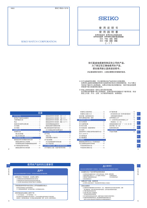
■ 电池残量可以通过秒针的走动状态来确认 → 确认电池残量 P.16
■ 关于太阳能电池 → 充电方法 P.30
→ 充电所需要的大致时间 P.31
1
■ 怎样接收电波信号
关 于
本
本腕表每天自动接收电波信号,校准时间。
产 品
自动接收电波信号的时间是凌晨2点和凌晨4点。
在这个时间段,不要把腕表戴在身上,而应该把腕表放置在容易接收到电波信号
注意事项
1
在手上沾有水分的时候,
关 于
不要操作腕表的表把或按钮
本
产
有可能会使水分进入表的内部。
品
※ 万一玻璃面内侧出现了水雾气或水滴,且长时间不消失的话,则说明防水有问题。 应该尽早与购买商店或公司的客户服务中心取得联系。
当表上沾有水滴、汗水和污渍的时候, 不应放置不管
即使是防水表也会因玻璃黏和面或垫圈老化以及不锈钢生锈而导致防 水出现问题。
·如果出现了过敏、斑疹的话
应立即停止腕表的使用,并到皮肤科等专科医生之处就诊。
·其他注意事项
○金属表带的调整需要专业知识和技术,所以,调整表带时应该与购买商店联系。如果 自己调整的话,则有可能导致手或手指受伤,也有可能导致零部件遗失。 ○不要对商品做拆卸或改造 ○注意不要让婴幼儿接触腕表。 有可能会导致受伤或过敏。 ○关于使用完后的电池的处理,应遵守各地方行政部门的相关规定。 ○在使用怀表和胸饰表的话,请注意绳带和表链的使用方法。 使用不当则有可能会损坏衣服或弄伤手和颈部或者勒脖子。
→ P.18
也可以通过手动来强制性接收电波信号。
可以接收日本(2台站)和中国、美国、德国的电波信号。(通
过时差修正功能选择接收信号台站。)
■ 接收信号水平显示功能・・・・・・在电波信号接收过程中,秒针显示接收信号的状况。
FLIR 数字多功能抄测仪指南说明书

FLIR is proud to offer a high-quality line of digital multimeters for every need, whether it’s for an industrial application or a DIY project.Our selection of digital multimeters now includes options with built-in thermal imaging – we call it IGM™ (Infrared Guided Measurement). FLIR tools enhanced with IGM give you the power to quickly identify the precise location of potential problems. IGM also helps you to identify failing components early so you can work faster, work smarter, and move on to the next job.Troubleshoot easier with the unique combination of onboardthermal imaging and traditional Digital Multimeter test functions.DIGITAL MULTIMETERS WITH IGM ™View thermal andelectrical measurements Color display with wide Intuitive menu systemBright LED worklight LoZ mode prevents false Fully loaded measurementfeatures for high- and low-voltage applicationsIP54 splashproofTest-lead holder160 x 120 resolution thermalimager for non-contacttemperature measurementAll-in-one digital multimeters and thermal imagers for fast inspections of industrial-electrical, mechanical,HVAC/R, and electronic systems.KEY FEATURES • Safely scan for issues with the built-in 160 x 120 FLIR thermal imager • Operate easily with an intuitive menu systemand a built-in worklight• Troubleshoot complex high- and low-voltageapplications with full-featured multimeter DM285 UNIQUE FEATURES• Connect wirelessly to FLIR Tools ® or the newFLIR InSite™ workflow management app• Save electrical parameter data and thermalimages with onboard data storage• See readings clearly on the TFT display with awide viewing angleDM284/285INDUSTRIAL IMAGING MULTIMETERS WITH IGM™Laser pinpoints exacthot spot locations Send readings via METERLiNK ® tocompatible FLIR infrared camerasto embed data into live or savedthermal images Replace batteries withoutany toolsmeasurement80 x 60 thermal imager toquickly scan for overheating Full color LCD displayIGM button activates thermalimaging3 m drop-tested durability Rich DMM features forboth high- and low-voltageapplicationsDM166The most affordable multimeter with built-in thermal imaging – a must-have tool for commercial electricians aswell as automation, electronics, andHVAC/R technicians.KEY FEATURES• Safely scan for issues with the built-in 80 x 60 FLIR thermal imager• Troubleshoot complex high- and low-voltage applications with full-featured multimeter • Carefully measure voltage with integrated non-contact voltage detection• Remove high-frequency noise that affects readings with VFD modeLaser pinpoints exact hot spotlocations Replace batterieswithout any tools IMAGING TRMS MULTIMETER WITH IGM ™Store up to 40Kmeasurements withdatalogging modeBright LED worklight Non-contact voltagemeasurementLoZ prevents false readingsFully loaded measurementfeatures for high- andlow-voltage applications 3 m drop-tested durabilityIntuitive user-interfaceDM90/91Affordable, safe, and reliable multimeters for a wide range of electrical, electronic, and HVAC/R systems.TRMS MULTIMETERS WITH TYPE-K TEMPERATURE KEY FEATURES • Diagnose complex systems with high- and low-voltage measurement capabilities • Assess temperatures up to 400°C (752°F) with Type-K thermocouple • Work safely with built-in, non-contact AC voltage • User-friendly design with an intuitive interface and enhanced ergonomics • Work longer with flexible battery options, powerful LED worklights, and rugged, drop-tested design DM91 UNIQUE FEATURES • Detect and document intermittent trends using the datalogging mode with on-board storage of 40k measurements • Connect to FLIR infrared cameras or to mobiledevices via Bluetooth ® METERLiNK ® to embed data into live or saved thermal images• Wirelessly connect to FLIR Tools™ or the FLIR InSite™ workflow management application, for efficient troubleshooting and streamlined inspectionsDM92/93World-class digital multimeters with advanced variable frequency drive filtering that accurately analyze non-sinusoidal waveforms and noisy signals.KEY FEATURES • View voltage and frequency together with dual display • Eliminate ghost voltage error readings with low impedance (LoZ) mode • See readings clearly with the display backlight • Illuminate dimly lit areas with the powerful LED worklight • Durable double-molded construction: IP54 rating, 3 m drop-tested • Large, easy-to-read digits, backlit display, and analog bar graph DM93 UNIQUE FEATURES • Integrated Bluetooth technology connects to the FLIR Tools Mobile app on compatible mobile devices • Send readings via Bluetooth compatible FLIR infrared cameras to embed data into live or saved thermal images • Data record captures electrical measurements and provides wireless data transferTRMS INDUSTRIAL MULTIMETERS Send readings via METERLiNKto compatible FLIR infrared cameras to embed data into live or saved thermal images*Store/recall 99 readingsBluetooth connectivity for wireless data transfer**DM93 model only Advanced variablefrequency drive filtering Bright LED worklightLoZ prevents false readings IP54 splashproof3 m drop-tested durabilityBright backlight2 m drop-tested durabilityView frequencyLoZ mode prevents2 m drop-testeddurabilityEasy-access buttons forone-handed operationEasy-to-navigate on-screen menu systemDM62/66Meters of exceptional value that provide rich features, precise measurements, and quality construction for commercial electricians, automation field service professionals, electronics repair technicians, and even do-it-yourselfers.KEY FEATURES• Measure both AC/DC voltage and current • Safely check voltage with non-contact voltage detection • Operate the meter with one hand, thanks to compact design and easy-access buttonsDM66 UNIQUE FEATURES• Low impedance mode (LoZ) to prevents ghost voltage from delivering false readings • Measure frequency, diode, and capacitance • Measure temperature up to 400°C (752°F) with Type-K thermocoupleTRMS DIGITAL MULTIMETERS FOR ELECTRICAL AND FIELD SERVICETemperature measurementLoZ mode prevents false readingsView frequencyTest flame sensors with microamps measurementEasy-access buttons for one-handed operationEasy-to-navigate on- screen menu systemBright backlightDM64Provides an unmatched feature set and high-quality measurements at an affordable price – perfect for professionals who install, inspect, and maintain HVAC/R systems.KEY FEATURES• Assess temperatures up to 400°C (752°F) with Type-K thermocouple • Test flame sensors with microamps feature• Readily and precisely identify live wires with probe-contact voltage detection • Work quickly and comfortably thanks to user-friendly design, intuitive interface, and enhanced ergonomics • Easily identify deviations from normal conditions by comparing new readings to stored data • Navigate the meter’s on-screen menu system easily • Swap batteries easily from the “no tool” battery compartmentHVAC TRMS DIGITAL MULTIMETER WITH TEMPERATUREIP54 splashproof3 m drop-tested durabilityStore/recall 99 readingsBluetooth ® connectivity for wireless data transferSend readings viaMETERLiNK to compatible FLIR infrared cameras toembed data into live or saved thermal imagesSpecialty insulation modes including: Polarization Index, Dielectric Absorption, and Earth Bond Resistance.TECHNICAL SPECIFICATIONSACCESSORIESCOMPLETE YOUR TOOLBAGFLIR has all the right accessories to help you maximize your benefits from your digital multimeter, including: • Test leads• Thermocouple probes• Rechargeable battery kits for select meters • Protective cases• Flex current probe accessoriesCheck out all of FLIR’s multimeter-compatible accessories at FLIR has a full line of products to make your job easier, including thermal cameras, voltage detectors, clamp meters, and IR thermometers.Check out all that FLIR has to offer at www.flir.eu/professional-toolswww.flir.eu/dmm-accessoriesE-mail:**************************。
《宜准说明书》
EZON 宜准GPS跑步运动表系列Professional GPS Running Series 使用说明书Operation Instruction Manual目录1.简介 (1)2.功能特征 (1)3.显示屏上的符号 (2)4.按键功能 (2)5.休眠状态 (4)6.电池充电 (5)7.功能模式 (6)8.计时功能 (6)8.1.查看时间 (6)8.2.设置时间与日期 (7)8.3.城市代码列表 (9)9.闹铃设置 (11)10.跑表功能 (12)10.1.进入跑表模式 (12)10.2.单段计时 (12)10.3.圈计时 (13)10.4.跑表数据查询 (14)11.设置用户资料 (14)12.GPS功能 (16)12.1.GPS简介 (16)12.2.开启GPS (16)12.3.查询实时运动信息 (18)12.4.运动分圈 (19)12.5.暂停、关闭GPS模式 (21)12.6.查看、删除运动记录 (22)13.背景光 (24)14.防水性 (24)15.注意事项 (24)16.产品规格 (25)1.简介感谢您购买EZON GPS跑步运动表,在使用之前请仔细阅读说明书。
了解该产品的功能、操作方法及注意事项。
本表为带有GPS接收器的多功能手表,不但具有时间、日历、闹铃等功能,还能GPS授时并实时监测运动过程中的配速、速度、距离及卡路里燃烧等,并可存储和查看最近10次的运动记录,电池具有较长的续航时间。
本表出厂时设为休眠状态,使用前先解除休眠状态(参见第5章节)。
2.助能特征GPS授时速度与配速运动距离3.显示屏上的符号低电提醒符号GPS开启后,按[E]键,进入GPS模式。
在设置菜单:1)按[B]键,返回时间模式。
2)按[C]键或[D]键,循环选择选项。
3)按[E]键,确认选择。
在设置状态:1)按[B]键,确认设置并进入上一个选项。
2)按[C]键,改变设置或减少数值;按住[C]键,快速减少数值。
casio电波表说明书

使 用 手 册 3195MO0911-CkA事前须知承蒙惠购 CASIO 手表,谨表感谢。
为了最有效地使用本表,务请详细阅读本说明书。
请让手表照射到明亮光线本表内置的充电电池会储存由太阳能电池产生的电能。
在照射不到光线的地方放置或使用本表会使电池的电量耗尽。
请尽可能地让手表照射到光线。
•不将手表戴在手腕上使用时,请将手表面朝明亮光源放置。
•请尽量使手表露在衣袖之外。
部分表面被遮挡时充电效率会显著下降。
ll l l l l l l l ll明亮光线太阳能电池电池在光线下充电。
电池在黑暗中放电。
•即使照不到光线,本表也将保持运作。
让手表长期处于黑暗环境中会耗尽电池,并使手表的有些功能停止。
若电池耗尽,您将不得不在充电后再次配置手表的各项设定。
为确保手表的正常运作,必须尽可能地让手表照射到光线。
•使部分功能停止的实际电量水平依手表的型号而不同。
•经常点亮照明会很快耗尽电池并使手表需要充电。
下面介绍在点亮一次照明后,为补足消耗的电量所需要的充电时间。
在透过窗户照射进来的明亮阳光下时约为 5 分钟在室内荧光灯下时约为 8 小时•请务必参照“电源”一节,了解有关让手表照射到明亮光线时需要知道的重要资讯。
若手表画面变为空白若手表画面变为空白,则表示为了节省电源,手表的节电功能已将画面关闭。
•有关详情请参阅“节电功能”一节。
请注意,卡西欧计算机公司(CASIO COMPUTER CO., LTD.)对于用户本人或任何第三方因使用本产品或因其发生故障而引起的任何损害或损失一律不负任何责任。
关于本说明书•手表画面的文字显示有白底黑字及黑底白字两种,依手表的型号而不同。
本说明书中的所有范例画面均以白底黑字表示。
•按钮以图中所示的字母表示。
•本说明书的每一节都会介绍一种功能的操作。
有关技术资料等详情请参阅“参考资料”一节。
倒数定时器模式秒表模式闹铃模式▲世界时间模式▲▲▲部位说明•按 C 钮可选换各模式。
•在任意模式中(设定画面显示时除外),按 L 钮可点亮照明。
电波表说明书

电波表说明书最初的热悉祝贺你买到卡西欧表,为了发挥表的最大功能,请仔细阅读本说明书。
注意事项当在开时,表运来时即有自动显示特征(其能连续改变数字显示内容)。
当自动显示处于开时不能接收校正信号。
当压任何按钮时,即能关掉自动显示,回到计时模式。
关于说明书●按钮操作用字母示于图中。
●为了完成你所须要的各种模式的操作,本说明书的每一节都提供了相应的信息。
更详细的技术信息,见“参考说明”一节。
一般的指导●从一个模式转换到另一个模式可压按钮C。
●在任何模式下压按钮B,就有照明出现(设置屏处于显示状态除外)。
下图表示了模式的转换无线控制原子计时本表可以接收时间校正信号,依此信号更新时间。
●时间校正信号:德国(麦林根),英国(安顿),美国(柯林斯堡),日本(福岛、福岗)。
●如果你遇到了校正信号接收方面的问题,请见“信号接收故障”一节。
现时时间的设置本表可以依据时间校正信号自动的调整时间的设置,必要时也可手动设置时间和日期。
●买到本表后第一件事是验证你家所在城市能否正常使用本表,详见“家在城市的确认”●如果本表在时间校正信号传播覆装置区之外,设置时间应以手动方式进行,详见“计时”一节。
●在北美地区本表能收到时间校正信号,北美其词指加拿大、美国大陆与墨西哥。
确认你家所在城市1,在计时模式按住按钮A直到城市代码闪亮,显示出设置屏。
2,压按钮D与B选择城市代码与你家所在城市一样。
德国/英国信号日本信号美国信号城市代码城市名称城市代码城市名称城市代码城市名称城市代码城市名称城市代码城市名称LIS 里斯本ATH 亚典HKG 香港HNL 火努噜噜YWG 温尼伯湖市LON 伦敦MOW 莫斯科BJS 北京ANC 锚地CHI 芝加哥MAD 马德里TPE 台北YVR 温哥华MIA 迈阿密PAR 巴黎SEL 首尔LAX 落杉机YTO 多伦多ROM 罗马TYO 东京YEA 埃德蒙顿NYC 纽约BER 柏林DEN 丹佛YHZ 哈利法克斯STO 斯德哥尔摩YYT 圣,约翰重要事项●正常情况下,一经选择了你家城市代码,你的表就会显示正确的时间。
Radar Roy V1 Gen2 雷达警报器用户手册说明书

Software Version
Feature Indication
4.1xxx and hiction
X band ON (default) X band OFF Laser ON (default) Laser OFF Mute to Muted Volume (default) Mute to Zero Volume Bogey-Lock tone Loud after muting ON (default) Bogey-Lock tone Loud after muting OFF Mute all rear X or K in Logic or Advanced Logic OFF (default) Mute all rear X or K in Logic or Advanced Logic ON Ku band—Disabled (default) Ku band—Enabled Euro Mode—Disabled (default) Euro Mode—Enabled K-Verifier—Enabled (default) K-Verifier—Disabled Rear Laser ON (default) Rear Laser OFF Custom Frequencies—Disabled (default) Custom Frequencies—Enabled
G. How to exit the Programming Mode.
N Press-and-hold both Volume + and Volume – until the unit restarts. The changes you programmed will be retained in memory.
FLUKE示波表的使用手册

此保修是买方唯一的索取补偿的权益。在多种其它明示或默示保修,包括但不只限于那些为推销产品或与特殊目的相配合的默示的保证,同时存在的情况下,应以 此保修为准。对于在违反保修条例、合同、条约、承诺或任何其它条文时发生的例外的、间接的、偶然的及随之引起的损坏或损失,其中包括数据的遗失,FLUKE 不承担任何责任。 由于某些国家(洲)不承认默示保修的界限或不容许有对例外或相应损失的排除,故此保修中的限制条例与例外处理并不适用于任何买方。若保修条款中任一条被法 院裁决无效,这一裁决将不影响其它条款的有效实施。
Fluke Corporation, P.O. Box 9090, Everett, WA 98206-9090 USA(美国)或 Fluke Industrial B.V., P.O. Box90, 7600 AB, Almelo, The Netherlands(荷兰)
服务中心
欲安排一家授权的服务中心,请与我们在全球网(tçêäÇ=táÇÉ=tÉÄ)上的地址联络: 或者与下列任何电话联系: 在美国与加拿大:HNJUUUJVVPJRURP 在欧洲:HPNJQMOJSTRJOMM 从其它国家:HNJQORJQQSJRRMM
®
Fluke 123/124
fåÇìëíêá~ä=pÅçéÉjÉíÉê
用户手册
`e OMMO=年=V=月
«=OMMO=cäìâÉ=`çêéçê~íáçåK=版权所有。 所有产品名称均为其所属公司的商标。
有限保修及义务范围
在正常使用与维修情况下,cäìâÉ 保证每一个产品无质地及工艺问题。自发货之日算起,测试工具保修期为三年,附件保修期为一年。零配件及产品修理与维护的 保修期为 VM 天。此保修只限于原始购买者和 cäìâÉ 指定经销商的产品使用客户保修不适用于保险丝和普通电池,亦不适用于任何 cäìâÉ 认为因错误使用、改装、疏 忽或因事故或非正常条件下操作或处置而导致损坏之产品。在 VM 天内,cäìâÉ 保证软件运转符合功能规范,且保证软件正确录制于完好无损的介质上。cäìâÉ 不保 证软件毫无差错或无操作中断情况。 Fluke 指定经销商只能向客户对新的和未使用过的产品提供保修,而无权以 Fluke 名义扩充或更改保修内容。以 Fluke 指定的销售渠道购买的产品或按相应国际价格购 买的产品可以得到保修。当产品在一个国家购买而要送到另外一个国家去修理时,Fluke 保留收取修理/更换零件的权利。 对于在保修期内将有故障的产品送回维修中心,要求按原价退款、免费修理或更换,Fluke 的保修义务是有限的。 在需要获得保修服务时,请与就近的 Fluke 指定的维修中心联系,或在附上故障说明、邮费及预付保险(目的地交货价)后,将产品寄往就近的 Fluke 指定的维修中 心。对于运输中可能出现的损坏情况,Fluke 不承担任何风险。产品维修后,将寄回给客户,邮费预付(目的地交货价)。如果 Fluke 认为出现故障的原因是由于错误 使用、改装、事故或非正常情况下使用或操作,Fluke 将提供维修的估价并在得到认可后才进行维修。维修后,产品在由 Fluke 预付邮费后寄回给客户,客户须支付维 修和运输费用(起运点交货价)。
LONGINES手表说明书

2INTERNATIONAL WARRANTYL ONGINES is delighted you have chosen a time-piece from its collection, which lives up to the brand’s long-established know-how, based on re-search combined with technical excellence and timeless elegance.La Compagnie des Montres Longines, Francillon S.A. grants you, with effect from the purchase date, a twenty-four (24) month warranty on all LONGINES ® watches models and a five (5) year warranty on the automatic watches purchased from January 1, 2021, under the terms set out in this warranty. The L ONGINES international warran-ty covers defects in materials and manufacturing that exist at the time of delivery of the L ONGINES watch purchased (“defects”). The warranty takes ef-fect only if the warranty certificate has been dated and fully completed by an official L ONGINES deal-er (“valid warranty certificate”). During the term of the warranty and on presenting the valid warranty certificate, you are entitled to have any defect re-paired free of charge. In the event that repairs can-not restore your L ONGINES watch to full working order, La Compagnie des Montres L ongines, Fran-cillon S.A. undertakes to replace it with an identical L ONGINES watch or another L ONGINES watch with similar characteristics. The warranty for the replacement watch expires on the same date as the warranty for the replaced watch.The warranty does not cover:• battery life;• n ormal wear and tear (such as scratches on the case and/or glass; alteration of the colour and/ or material of cases, straps, bracelets and chains made of leather, textile, rubber or any other non-metallic material; the PVD coating; the colour of bronze);• d amage to any part of the watch resulting from unsuitable/improper use, neglect, carelessness, accidents (knocks, dents, crushing, glass breakage, etc.), incorrect use of the watch, or failure to follow the instruction manual;• h arm of any nature whatsoever resulting directly or indirectly from using the L ONGINES watch or from any operational failure, defect or lack of precision in the watch;• a L ONGINES watch having being handled by a non-approved person (for example, for the purposes of replacing the battery or carrying out servicing or repairs) or having been altered from its original state other than under the supervision of La Compagnie des Montres L ongines, Francillon S.A.Any other claims against La Compagnie des Montres L ongines, Francillon S.A., for example for any kinds of damage or harm other than those set out in this warranty, are expressly excluded, excepting statuto-ry rights that the purchaser can assert against the manufacturer.This manufacturer’s warranty:• i s independent of any warranty that may be provid-ed by the vendor and for which the vendor accepts sole responsibility;• i n no way affects the purchaser’s rights against the vendor nor any other statutory right the purchaser may have against the vendor.The Customer Service department of La Compagnie des Montres L ongines, Francillon S.A. ensures your L ONGINES watch is perfectly maintained. If your watch needs servicing, entrust it to an offi-cial L ONGINES dealer or an approved L ONGINES Service Centre as listed on our website at www. l : their servicing is guaranteed to comply with the standards of La Compagnie des Montres L ongines, Francillon S.A.* Compagnie des Montres L ongines, Francillon S.A., CH-2610 Saint-Imier, Switzerland.L ONGINES® is a registered trademark.3CONTENTSWe are delighted you have become the owner of a L ONGINES watch. We recommend you read this instruction manual carefully before using your L ONGINES watch for the first time in order to en-sure its correct operation and long life. If you would like more information about your watch or if it is fitted with a complication, you can find detailed in-formation and tutorials by going to our website at www.l /instruction-manual or by scanning the QR code.Precautions concerning water-resistance A watch’s water-resistance can be affected by changes caused by the gaskets drying out, or an ac-cidental shock to the crown. To help maintain your watch’s water-resistance, we recommend rinsing it in soft water after any contact with sea water and having its water-resistance checked once a year by an approved L ONGINES Service Centre. In no cir-cumstances should you open your watch yourself.IMPORTANT! Never activate the time-setting crown and/or push-pieces when the watch is underwater, and ensure that the crown and push-pieces are pushed in or screwed down before any immersion in water.*The water-resistance values given in metres are equivalent to pressure applied in accordance with standard ISO 22810.International warranty 2Water-resistance 3Setting the time 4L ongines warranty card 51 2 3 4 5None Not water-resistant No No No 3 bar Water-resistant to a pressure of 3 bar (30 m)*Yes Yes Yes 5 bar Water-resistant to a pressure of 5 bar (50 m)*Yes Yes Yes 10 bar Water-resistant to a pressure of 10 bar (100 m)*Yes Yes Yes 30bar Water-resistant to a pressure of 30 bar (300 m)*Yes Yes Yes1 indication on the case back2 meaning*3 rain, washing your hands4 showering, taking a bath, washing dishes, doing housework5 swimming, snorkelling35+*4SETTING THE TIME – GENERAL INFORMATIONScrew-in crown Some LONGINES models are fitted with a screw-in crown which must be unscrewed before setting the time, correcting the date or winding. After setting the time or winding, return the crown to position 1, then push it back in and screw it in firmly in order to ensure the watch’s water-resistance.Setting the time Pull the crown out to position 3 when the seconds hand is at 60. Turn the crown forwards or backwards until the desired time is displayed. Once the time is correctly set, push the crown back in to position 1.Quick date correction Pull the crown out to position 2 and turn it forwards to correct the date. While you are doing this, your watch continues to operate and so the time does not need resetting. The date needs correcting after any month with fewer than 31 days. Push the crown back in to position 1. The date changes when the hour hand passes midnight.Do not attempt quick correction of the date between 8 p.m. and 3 a.m.A CrownB HoursC MinutesD SecondsE Date52021L4.805.4.11.649385722You can also access this information via the QR code to be found in the instruction manual, or by going to: www.l /instruction-manualScanning the QR code on your watch’s warranty card with your smartphone’s camera gives you ac-cess to the L ONGINES website. There you will find the specific instruction manual for your watch, avail-able in 33 languages, together with advice for main-taining your watch and the warranty terms.L ONGINES WARRANTY CARD。
Omega CDCN系列电导仪产品说明书

CDSA-1413
23
1413 µmho/cm conductivity solution, 946 mL (1 qt)
CDSA-1500
10
1500 µmho/cm conductivity solution, 946 mL (1 qt)
Comes complete with operator’s manual and 3V lithium battery. Probes sold separately.
RS232, RS485 RS232, RS485
RS232 RS232 RS232, RS485 RS232, RS485
Keypad/Display 5-button/one line 5-button/one line 5-button/one line 5-button/one line 16-button/four line 16-button/four line 16-button/four line 16-button/four line
PHA-7
5
7.00 pH buffer solution, 500 mL (1 pt) bottle
PHA-10
5
10.00 pH buffer solution, 500 mL (1 pt) bottle
CDSA-45
10
45 µmho/cm conductivity solution, 946 mL (1 qt)
ߜ Three Chemical Feed Programs (Conductivity, pH and Additive)
ߜ Langelier Saturation Index for Water Balance
操作指南
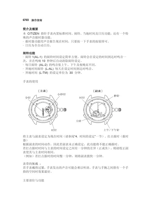
6765操作指南简介及概要本CITIZEN指针手表内置标准时间、闹铃、当地时间及日历功能,还有一个特殊的声音报时器功能。
·报时器功能用声音报告现在时间,只要按一下手表的按钮即可。
·日历为全自动日历。
闹铃功能·闹铃1(AL-1)的闹铃时间设定简单方便。
闹铃会在设定的时间到达时鸣音一次,并在鸣响10秒钟后自动清除闹铃设定。
·每日闹铃(AL-2)的鸣音依上午、下午及夜晚而不同。
·异地时间闹铃(L-AL)每天在设定时间到达时鸣音。
·异地时间(L-TM)的设定单位为30分钟。
手表的使用将主表与副表设定为现在时间(请参阅“4.时间的设定”一节)。
打点报时(报时器)根据副表的时间动作,因此若副表未正确设定,此功能将不能正确报时。
若打点报时时间与主表的时间设定之间有一分钟的差异(正或负),则请校正副表使其与主表时间相同。
(例如)若打点报时的时间慢一分钟,则将副表拨快一分钟。
表带的佩戴:若手表戴得过紧,手表发出的声音可能会难以听清。
手表与手腕之间留有一个手指的空间时效果最好。
主要部位与功能注:本表表示从上次闰年开始经过的年数。
注:上午/下午指针只能用于区分上午及下午。
不能用于24小时时制。
·外形设计可能依手表型号而不同。
⑴副表秒针⑹上午/下午指针·日历指针⑺主表小秒针·闹铃开/关针⑻(B)按钮⑵星期针·年/月设定模式针·年/月表示模式⑶(C)按钮⑼·位置1模式选择·日历调整星期设定⑽·位置2⑷·副表时针·时间调整·异地时间时针⑾标准位置·闹铃时针⑿(A)按钮·年针·打点报时(报时器)⑸·副表分针·日期设定·异地时间分针·闹铃开/关·闹铃分针⒀主表时针·月针⒁主表分针按钮的功能把的模式(A)按钮(B)按钮(C)按钮转动柄头标准位置标准模式*打点报时(报时器)*日历模式模式选择*指针初始位置的检查—日历模式切换至标准模式切换至标准模式切换至标准模式—闹铃1设定*闹铃音检查(关)取消闹铃(开)闹铃设定模式选择*指针初始位置的检查—闹铃2设定开/关选择*闹铃音检查闹铃设定模式选择*指针初始位置的检查—异地时间设定—异地时间设定模式选择*指针初始位置的检查—异地时间闹铃设定开/关选择*闹铃音检查异地时间闹铃设定模式选择*指针初始位置的检查—秒设定秒设定—模式选择*指针初始位置的检查—位置1(日历设定)日期设定闰年的月设定星期设定—位置2(时间设定)副表的秒设定副表的时、分设定—主表的时、分设定指针功能把的模式主表的时、分、秒副表的时、分上午/下午针日针模式针标准位置标准模式主表的时、分、秒异地时间的时、分异地的上午/下午(主表)日期(主表)星期日历模式主表的时、分、秒(主表)年、月—(主表)日期(主表)星期闹铃1设定主表的时、分、秒闹铃的时、分闹铃的上午/下午开闹铃1(AL-1)主表的时、分、秒(主表)时、分主表的上午/下午关闹铃1(AL-1)闹铃2设定主表的时、分、秒闹铃的时、分闹铃的上午/下午开/关闹铃2(AL-2)异地时间设定主表的时、分、秒异地时间的时、分异地时间的上午/下午(位于12时位置)异地时间(L-TM )异地闹铃设定主表的时、分、秒异地时间闹铃的时、分闹铃的上午/下午开/关异地时间闹铃(L -AL )秒设定主表的时、分、秒(主表)时、分(主表)上午/下午(主表)秒0位置1日历设定主表的时、分、秒年、月—(主表)日期(主表)星期位置2时间设定主表的时、分、秒(副表)时、分(副表)上午/下午(主表)秒时间的设定设定现在时间时,主表与副表要设定为相同的时间。
时间管理-本电波表接收中华民共和国播送的标准时间电波

充电不足时,秒针会每两秒走动一下。按照“充电时间指南”(第64页)一节 中的说明,给手表充电。
• 请每月一次地将手表较长时间置于直射阳光下 充电。
1
部件名称(1:有计算尺表圈的机型)
功能针 (星期、记时器分钟, 记时器1/20秒)
RX:接收就绪
(B)钮
NO:接收状态 时针
<确认接收状态>
要确定接收电波是否正确,请在试图接收电波后按位于4点位置的(A)钮。正确接 收电波时,秒针显示H、M或L。此时,本表可以使用。 没有正确接收电波时,秒针显示NO。 改变手表位置再次接收。
7
节能功能
手表因被收起或因被衣服遮盖而不受光照30分钟或更长,秒针将停在12点位置以 省电。 • 其他表针将继续正常走动。 • 一旦手表再次接受光线照射,节能功能将取消,秒针开始正常走动。 * 有关细节,请参阅“节能功能”(第62页)。
10
12.太阳能手表的特性 ......................................................................... 60 A. 节能功能.................................................................................. 62 <节能功能> .................................................................................... 62 <取消节能功能> ............................................................................. 62 B. 充电不足警告功能 ................................................................... 63 C. 防过度充电功能 ....................................................................... 63
более精确的ALA-52B电子高程计Airborne Radio Altimeter说明书

ALA-52B RADIO AL TIMETER Air Transport and Regional Technical SummaryALA-52BRADIO AL TIMETERThe ALA-52B Radio Altimeter (RALT), designed and manufactured by Honeywell Aerospace, is part of the Quantum™ line of communications and navigation equipment. The ALA-52B RALT, a lightweight, solid-state, airborne altimeter, provides accurate digital height measurements above terrain during aircraft approach, landing, and climb-out phases. The operating range is –20 feet to +8000 feet. The ALA-52B has recently been upgraded with new hardware and software toprovide enhanced reliability and improved robustness to external signal leakageor direct coupling of TX and RX signals. Leveraging the all new Radio Altimeterdeveloped for the Boeing 787, Honeywell has ported the new fully-digital RFmodule design over to the ALA-52B.ALA-52B RALT TECHNOLOGY ADVANTAGEThe ALA-52B RALT contains fault memory and provides built-in test equipment (BITE) interfaces for use in a Central Maintenance Computer (CMC) or in a Centralized Fault Display System (CFDS) in compliance with ARINC 604 and Airbus Industrie ABD-0048.The ALA-52B RALT requires two antennas; one for transmitting and one for receiving the RF signals, and a multifunction or dedicated indicator for display of altitude information.The key features of the ALA-52B RALT are listed below:• 4.2 GHz to 4.4 GHz operation• Range: -20 to +8,000 feet (-6,1 to 2438 metres)• Accuracy: ± 1.5 feet (0,46 metres) or 2%• Transmit Power: 1 Watts (nominal)• 3 MCU form factor (ARINC 600)• ARINC 429 Tuning Interface• CMC/CFDS Maintenance System Interface• 200 millisecond Power Interrupt transparency• DO-160C Environmental Test compliant• High Intensity Radiated Fields (HIRF) protection• Lightning protection• 18 0 minute ETOPS cooling• Front Panel LCD Display• PCMCIA “Flash Memory” Interface• RS-232 PC maintenance port TROUBLESHOOTINGAND MAINTENANCEWhat uniquely distinguishes the ALA-52B RALT from similar products is the LCD (Liquid Crystal Display) locatedon the front panel. This provides part number, software version and detailed troubleshooting and maintenance information in plain English. Self-test is initiated and detailed troubleshooting can be performed by simply pushing one of two buttons located on the front panel. Maintenance personnel can review the status of discrete inputs to the unit, verify tuning words, and review fault history (up to 64 flight legs are stored in non-volatile memory) – again, all at the push of a button.Software loading is also simplified by the use of the built-in PCMCIA card interface, also located on the front panel. The software loads in a fraction of the time compared to legacy systems, and onlya single flash memory card is needed instead of the traditional handful of floppy disks.3 | | ALA-52B Radio AltimeterRELIABILITYThe ALA-52B was designed as part of the Honeywell radio range to overcome reliability issues encountered with older ARINC 707 type radio equipment:• Reduce parts count by 25%• Reduce interconnections by 33%• Increase MTBF (Mean Time Between Failures) by 50%An integrated product design team, consisting of representatives from all departments including engineering, materials, manufacturing, test, product support and marketing, worked together to ensure that goals were not only met but also exceeded. The ALA-52B has 30% fewer parts than previous designs.A higher level of component integration resulted in only five modules being used in the ALA-52B, versus eleven modules in older designs. Fewer modules mean fewer interconnections, eliminating motherboards and extra ribbon cables. The ALA-52B was subjected to HALT (Highly Accelerated Life Testing), during which the radio was tested attemperatures well beyond normaloperating extremes and also exposed tovibration levels beyond those specifiedin RTCA DO-160C. This comprehensivetesting was done in order to evaluate therobustness of the design and determineareas for improvement. In production,each ALA-52B also undergoes HASS(Highly Accelerated Stress Screening)testing. The levels are slightly lowerthan those established during HALTtesting to avoid damaging the radio,but still high enough to ensure solderdefects, component defects, and processproblems are found and subsequentlyeliminated.So what does this mean for the end user?• Fewer parts and reducedinterconnections mean there is lesslikelihood of component failures inthe unit.• HALT testing proves that the ALA-52Bcan withstand extremes beyond thoseseen in normal operation.• HASS testing in accordance with ISO9001 procedures ensures a high-quality, high-reliability product, whichin turn means that the ALA-52B willstay on the aircraft for a longer periodof time – in fact, the warranted MTBFfor the radio is 30,000 hours. Datacollected from airlines indicates theALA-52B will far exceed this goal.WARRANTYTo back up the warranted MTBF of30,000 hours, the ALA-52B also comeswith a three (3) year warranty as standard,which means the radio is “fit and forget”.Should repairs be necessary, the simplemodular approach ensures rapid turn-around repair times.ALA-52B Radio AltimeterALA-52B Radio Altimeter | |4N61-3092-000-000 I 03/22© 2022 Honeywell International Inc.For more informationFor more information on Honeywell’s ALA-52B RALT, please contact your Honeywell sales representative or call: North America: +1 800.601.3099 orOutside North America: +1 602.365.3099.Honeywell Aerospace1944 East Sky Harbor Circle Phoenix, AZ 85034SUMMARYHoneywell’s ALA-52B RALT was designed to the following standards and specifications:• ARINC 707-6 “Airborne Radio Altimeter (RALT)”• RTCA DO-155 “Minimum Operational Performance Standards (MOPS) for Airborne Low-Range Radio Altimeters”• EUROCAE ED-30 “Minimum Performance Specification for Airborne Low-Range Radio (Radar) Altimeter Equipment”The ALA-52B RALT is also a very highly-reliable product having easyaccess to troubleshooting and maintenance with a 3 year warranty.。
