640说明书 中文版
联想RD640说明书
Sound Pressure (operating)
44.1 dB(A)
42.91 dB(A)
Sound Pressure (idle)
44.4 dB(A)
43.8 dB(A)
Lenovo
1
2
4
34
3
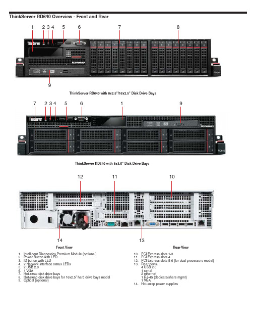
Processors and Memory DIMM Sockets (under cooling shroud)
1. CPU 1
2. 12 Memory DIMM sockets for CPU 1
3. CPU 2 (optional)
1
4. 8 Memory DIMM sockets for CPU 2 (for dual processors model)
Four USB 2.0, one serial (9-pin), two ethernet (RJ-45), one RJ-45 (dedicate/share mgmt), one analog VGA DB-15 connector
5 - PCIe x16 6 - PCIe x8
1 - PCIe x16 2 - PCIe x8
Category
Normal Configuration
Best Configuration
CPU
1
2
HDD
2x 900GB 2.5" SAS 6Gb/s
16x 900GB 2.5" SAS 6Gb/s
Memory
1x 8GB 1600MHz LVRDIMM
20x 8GB 1600MHz LVRDIMM
Temperature non operating (with package)
EPSON XP640SP用户手册说明书
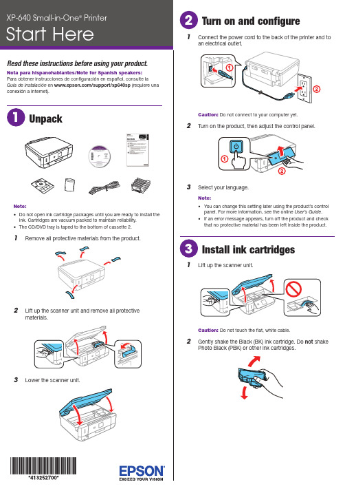
o not open ink cartridge packages until you are ready to install theink. Cartridges are vacuum packed to maintain reliability.he CD/DVD tray is taped to the bottom of cassette 2.Caution: Do not connect to your computer yet.2 T urn on the product, then adjust the control panel.3 S elect your language.Note:• Y ou can change this setting later using the product’s controlpanel. For more information, see the online User’s Guide.• I f an error message appears, turn off the product and checkthat no protective material has been left inside the product.1 L ift up the scanner unit.Caution: Do not touch the flat, white cable.2 G ently shake the Black (BK) ink cartridge. Do not shakePhoto Black (PBK) or other ink cartridges.See the online User’s Guide for information about availablepaper types, sizes, loading capacity, and loading CD/DVD/Blu-ray™ discs.You can load the following paper sizes:• Cassette 1: 3.5 × 5-, 4 × 6-, or 5 × 7-inch photo paper • Cassette 2: Letter-size, A4-, legal-size, or 8 × 10-inch paper See the instructions below for loading paper.1 Lower the front cover and raise the control panel.2Pull out a paper cassette.Cassette 1Cassette 23 S lide the side edge guides outward and set the front edgeguide to the paper size you are using.Cassette 24 I nsert the paper with the glossy or printable sidefacedown.Cassette 1N ote:Make sure the paper is loaded against the front edgeguide and not sticking out from the end of the cassette.5 S lide the side edge guides against the paper, but not tootight. Make sure the paper is under the tabs on the sideedge guides.Cassette 1Cassette 2Mobile printingConnect wirelessly from your smartphone, tablet, or computer. Print documents and photos from across the room or around the world:• P rint directly from your iPhone, iPad, or iPod touch. Simplyconnect your printer and device to the same network and tap the action icon to print.• U se Epson Print Enabler (free from Google Play™) with Android™ devices (v4.4 or later). Then connect your printer and device to the same network and tap the menu icon to print.• P rint remotely with Epson Connect™ and Google Cloud Print™. See your online User’s Guide for instructions or learn more at .Any problems?Network setup was unsuccessful.• Make sure you select the right network name (SSID).• Restart your router (turn it off and then on), then try toconnect to it again.• The printer can only connect to a network that supports 2.4 GHz connections. If your router offers both 2.4 GHz and 5 GHz connections, make sure the 2.4 GHz network is enabled.• If you see a firewall alert message, click Unblock or Allow to let setup continue.• If your network has security enabled, make sure you enter your network password (WEP key or WPA passphrase) correctly. Be sure to enter your password in the correct case.There are lines or incorrect colors in my printouts.Run a nozzle check to see if any of the print head nozzles are clogged. Then clean the print head, if necessary. See the online User’s Guide for more information.The product’s screen displays an output tray message.Make sure the product’s output tray is fully extended.The product’s screen is dark.Press any button to wake your product from sleep mode.Setup is unable to find my product after connecting itwith a USB cable.Make sure the product is turned on and securely connected as shown:67P ull out the output tray until it stops and lower the controlpanel.8 S elect the paper settings on the product’s control panel.Install softwareNote: If your computer does not have a CD/DVD drive or you are using a Mac, an Internet connection is required to obtain the product software. To print from a Chromebook™, go to /support/gcp (U.S.) or www.epson.ca/support/gcp (Canada) for instructions.1 M ake sure the product is NOT CONNECTED to yourcomputer.W indows ®: If you see a Found New Hardware screen, clickCancel and disconnect the USB cable.2I nsert the product CD or download and run your product’ssoftware package:/support/xp640downloads (U.S.) or www.epson.ca/support/xp640downloads (Canada)3 F ollow the instructions on the screen to run the setupprogram.OS X: Make sure you install Epson Software Updater to receive firmware and software updates for your product.4 W hen you see the Select Your Connection screen, selectone of the following:• Wireless connectionIn most cases, the software installer automatically attempts to set up your wireless connection. If setup is unsuccessful, you may need to enter your network name (SSID) and password.• Direct USB connectionMake sure you have a USB cable (not included).XP-640 replacement ink cartridgesStandard-capacity High-capacity410410410。
AU640 中文说明书2

本章描述了AU640 自动生化分析仪的安装使用环境标准附件注意事项及其他相关的要求请在使用仪器前阅读此部分为安全高效的使用自动生化分析仪必须遵守使用须知目录1. 安全事项A-022. 使用须知A-043. 安装环境A-054. 标准配件A-095. 警告标志A-101. SAFETY CAUTIONS安全事项安全和有效的使用仪器请遵守下列条件Prevention of Breakage and Flammability 防止破损和燃烧请注意观察下列预防事项以防仪器破损或易燃性WARNING警告仪器必需按照本手册内的安装环境和安装条件正确安装当设备须改变环境时请联系我们公司的技术服务部或销售部Preventing Electric Shocks 电冲击预防电路震动避免被仪器电击伤注意下列预防事项WARNING警告决不移动盖上的螺丝如后面及侧面的板的螺丝如果发生液体溢出或泄漏到仪器内联系OLYMPUS技术部忽略液体的存在可能导致电击Preventing Personal Injury人员受伤预防使用仪器时保护自己避免受伤观察下列预防事项CAUTION注意在仪器工作中不要触摸仪器的移动部件包括样品探针试剂探针和搅拌棒不要将手指或手伸进仪器敞开的地方更换灯泡关闭电源5分钟使其冷下来再换灯变凉前不要触摸它或许可能烫伤 遵守本手册的预防表要求关于PC机和打印机的预防事项参见随仪器一起提供的PC机操作手册和打印机操作手册Eye Protection 眼睛保护保护眼睛请遵守下列要求CAUTION注意仪器在开启状态灯亮着时请不要直接用眼睛看光源及激光条码读数器光源和激光束可能导致眼睛损伤Accuracy and Precision of Analysis Data 分析数据的精密度和准确性为了获得准确数据注意下列事项CAUTION注意在分析中不要打开上盖及后档板使用仪器前请做用质控检查仪器功能的准确性遵照本手册对仪器进行保养检查及更换部件处理试剂QC参考物请遵照相应的说明处理根据使用说明处理样品在分析时不要打开试剂仓盖和比色杯轮盘盖Treating Waste Liquids 废液处理废液及混合液在排出前要做特殊处理本系统原始废液和冲洗废液分开注意下列事项CAUTION注意试剂QC参照物清洗剂中的某些物质不符合污染管理及排放标准根据排放标准处理这些物质如何处理请遵照试剂制造者或销售商的建议Preventing Infection预防感染若仪器错误的处理样品有感染的风险为保护自己请遵守下列要求CAUTION注意不要用裸手接触样品混合物及废液使用手套以防感染若样品接触到你的皮肤立即按用户工作标准处理或咨询医生立即擦去仪器上的污物Handing the Reagent 试剂处理仪器上使用的某些试剂是强酸或强碱为了避免受伤注意下列事项CAUTION注意某些试剂是强酸或强碱不要直接接触手和衣物如果手或衣物与试剂接触立即用肥皂和水清洗如果试剂溅进如眼睛至少用水冲洗15分钟且看医生Preventing Damage to Other Equipment and Facilities 防止其他设备和工具的伤害WARNING警告连接合适的输出电源以防影响其他设备提供独立电源或导致仪器故障2. PRECAUTIONS ON USE 使用须知安全有效的使用仪器遵守下列要求General Precautions During Use of the System 处理分析仪使用的样品CAUTION注意在处理样品时的注意事项-可用于分析的样品此仪器可处理血清和尿样品根据分析试验和使用的试剂一些样品不能可靠的分析对于这些样品请咨询试剂制造者及销售商使用的样品要充分的分离出血凝块血或尿中的悬浮物若血清尿不能充分的分离其中的悬浮物会堵样品针影响分析结果样品内存有化学品(药物抗凝剂防腐剂)可能引起分析样品的重大干扰请注意在处理样品时的注意事项-样品储存一般样品的保存收藏参考说明不正确的保存方式可能改变样品的结构成分组成例如冷藏血将导致血中K离子浓度增加 在处理样品时的注意事项-预处理样品悬浮在血清中Fibrin纤维蛋白原可能会堵针在分离血清前检查血球是否充分凝聚上机测试前弃去悬浮的纤维蛋白原如果尿标本中有可见悬浮物在测定前将该尿标本进行离心沉淀如果试验要求对样品进行预处理咨询试剂制造者或供应商关于血清的适当分离的说明,咨询相应的试剂制造厂分析需要非常小量的试剂按本手册设置一个适当的试剂量为防止样品汽化不要使样品长时间放在空气中若汽化将无法得到正确分析结果在准备试剂参比物质和质控血清时的注意事项用分析仪分析血或尿标本时需要相应的试剂参考物及QC血清试剂及其他商品已经商业化关于试剂使用说明联系相关的制造商或供应商试剂的保存处理使用方法参考物及QC按制造供应商提供的说明操作保存试剂参考物及QC的方法标在包装或配套的说明内若试剂参考物及QC保存方法不正确即使在有效期内也不能得到正确的结果试剂在开放环境内的稳定期等事项咨询相应的试剂生产商或供应商在系统中设置试剂按手册及试剂供应者的说明设置只有正确设置了试剂才可得到相应的正确结果更换试剂应做校正否则将不能保证分析结果的准确试剂间的干扰分析项目若在分析过程中试剂被其它试剂污染则将影响结果关于试剂间多少量有影响的详细说明咨询供应商怎样检查交插污染咨询OLYMPUS技术部门分析过程的注意事项若血清是严重溶血乳糜或黄疸使用药物和代谢物等样本可能会影响分析结果详细说明联系试剂供应商或厂商商议试剂分析情况给水及排水按照设备结构说明指导联接上水及排水管若那些管道还连接着其它设备的支路则可能在操作中引起系统管路中产生气泡提供给仪器的去离子水不能含有气泡电防止磁波及噪声的干扰勿将有不正常噪声的设备放在仪器附近并关闭手机及收发报机在仪器安装的房间中因为电磁波将影响CRT及DPRCAUTION注意保证系统进行正常分析的环境仪器工作时温度应在18-32摄氏度湿度40-80%RH之间温度波动2°C使用的去离子水温度范围介于5~28摄氏度超出此范围将无法保证分析键盘显示器鼠标mouse为防止键盘显示器鼠标的损坏不要用湿手或化学物接触操作系统介绍传送分析结果检测样品数量ID正确传送每一个测定数据按照本手册操作仪器错误的操作会引起错误的结果及损坏仪器学习全部系统操作完成OLYMPUS提供的培训课程手册的使用人员应该接受过OLYMPUS提供的培训或接受过培训的人员培训过检查分析过程按系统管理标准和用户的标准工作程序检查以下项目检查水的质量检查定标结果检查QC数据检查分析结果检查稀释器管路气泡检查样品的污染灰尘纤维蛋白原检查每个样品的质量没有气泡出现 系统维护检查和定期部件更换按手册定期保养检查及更换部件只有正确保养仪器才能得到正确的分析结果如更换主要部件如光源注射器探针比色池等要做校正参考物的校正次数周期咨询供应商或厂商只能使用本手册提到的洗剂类型密度若使用其它洗剂不能保证结果use of consumables消耗品的使用若使用其它消耗品代替Olympus部件将影响系统运行要求永远使用Olympus部件 设置分析参数注意事项系统需要设定样品量试剂量波长校正值等按照试剂盒提供的说明和手册设置 其它注意如果试剂与粘膜接触且不小心吞咽立即冲洗呕吐按厂商或供货商的说明处理Instruction 使用说明在HD硬盘上备份数据若硬盘上的数据被抹掉或由于电源失败导致的HD损坏数据不能恢复定期备份数据及参数删除不需要的数据保留足够的空间HD独立使用分析仪不要在系统上做其它事它将会产生软件病毒现今有些设计恶意的软件破坏程序和数据在电脑世界里引起一系列问题这种软件提供计算机病毒病毒通过软盘或其他方式进入计算机代替程序和数据清洗表层的污物为了延长仪器的使用寿命立即清洗表层污物3. INWTALLATION ENVIROPNMENTS 安装环境Installation Environment Conditions 安装环境条件没有阳光直接照射灰尘非常少的环境平坦少余1/200没有震动地板承重600Kg电源波动10% 海平面2000m以下Temperature and Humidity Conditions 温度湿度条件温度1832摄氏度工作时波动大于2摄氏度湿度4080%RH并无冷凝若室温不能稳定则需要安装空调因为仪器运行时散热仪器背面的温度高于室温所以仪器安装的位置应该通风好安装场地通风好仪器不应该暴露在流动空气中Installation Space Requirements 设备安装空间场地要求图显示如下周边距离是安全安装和保养的要求*紧急情况时快速关闭电源至少需要220mm的空间系统主要单元面积单位mm分析仪ANL长1850宽800高1245数据处理DPR长700宽700高1430Power Source and Grounding 电源和接地仪器交付以前必需如下准备电源配电盘位于10m以内电源 Power source电压 AC220V10% 50HE 功率4KVA 分配盘10M 连接电源线下图A-10如下图连接电源和配电盘Grounding terminal 接地接地端结构为了条线线路电阻少于100的对地电阻警告连接地线以防电击和仪器故障.Water Supply and Drainage 给水及排水仪器交付以前必需如下准备给水和排水仪器使用去离子水去离子水器安装在距水龙头10米以内去离子水及排水孔安装在距仪器10M内去离子水装置的要求给水水压0.49 105到3.92105 Pa用水量33L/小时(50HZ/60HZ)单元类型643-04644-04643-0640/小时(50HZ/60HZ)单元类型641-04642-04641-06最大用水量 1.5L/分钟(50HZ/60HZ) 单元类型643-04644-04643-062.7L/分钟(50HZ/60HZ) 单元类型641-04642-04641-06排水排水孔排水孔的高度距地最高低于100mm若安装有压力排水装置选件排水孔可设置在1.5m以下一些试剂中含有不符合排放标准及污染物质,请咨询供应商从仪器中排出的废液如下废液的种类排出量/测试数预计浓缩废液样品+试剂 4L/800test1小时(试剂数平均300ul/测试) 冲洗废液(冲洗水+洗液) 29L/800test(1小时) 单元类型643-04644-04643-0636L/800test(1小时) 单元类型641-04642-04641-06提示通过检查单元背面的标牌盘检查单元类型CAUTION注意处理传染病的废液,要装排废液管连到医院的传染病处理装置处Installing a Deionizer 安装去离子水装置AU640自动化仪使用去离子水冲洗及进行试剂稀释去离子水符合下列条件643-04644-04643-06单元类型去离子水的平均流量33L/1小时最大直接使用1.5L/分钟641-04642-04641-06单元类型去离子水的平均流量40L/1小时最大直接使用2.7L/分钟水的信息参见给水和排水纯净水的要求电导率低于2 ms/(或电阻率大于0.5M)用0.5mm的过滤器过滤细菌如果提供的水温低根据去离子内部压力条件去离子水可能形成气泡如果这样它将严重的影响分析精确度参考水机商的建议避免去离子水产生气泡Wiring and Piping 线路和管路按下面示意设置线路管路系统应安装在距配电盘10M内电源线的长度系统应安装在距供水装置10M内上水管的长度排水管距地不得高于0.1M压力排液时为1.5M以内CAUTION注意不要折叠或压扁排水和排汽管道管道尾部敞开插管时不要堵住排水管口由于背面的废液溢出可能会损伤仪器可以出现错误数据如果选择外力排水将避免出现上述问题4.LIST OF STANDARD ACCESSORVES 标准附件表仪器标准附件列表如下List of Standard Accessories 标准配件表ITEM项目 QUANTITY数量样品架子15 白色10黄绿蓝红橙各1条码3套 1-20 一套 21-40 一套1-3 一套114个23个33个通针 2恒温液 2 2 L/桶比色杯1套10个管道上水 2管道下水 2管箍 4样品针 1试剂针 1光源灯 1手册 1程序1套工具 2挡板20个/套3套30ML用15ML用转口A急诊台用 1 套22个标识1套4种为急诊台定位置用通讯线 2隔板1套用于分隔试剂盘80片ISE选择项目数量P型管 1挤压阀管 1ISE保养手册 1 ISE操作手册补充卷内容5.ALARM LABET APPEARANCE警告标志表在系统外表可以看到一些警告标志ALARM LABEL OUTLINE 警告标志概述警告标志指示该部份需要在安全方面重视的要求请遵照警告标志所提要求去做 不要不轻易删除警告内容不能损坏移动标志如果警告标志损坏或分离请联系我们公司的销售部或技术部警告标志按等级划分WARNING/CAUTION Label Pictograms 警告/注意标志图标通常表示危险警告注意参看手册内相关部分的注意符号有电危险机械危险不能触摸高温危险发光二极管的危险警告/注意标志的位置和显示。
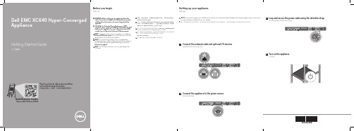
戴尔易安信XC640 超融合一体机入门指南说明书
技术规格
以下仅是依照法律规定随您的设备附带的规格。有关您的设备规格的当前完整列表,请访问 /XCSeriesmanuals。
电源: 2000 W 铂金 AC 100–240 V,50/60 Hz,11.5 A
注:如果设备使用低压线路 100-120 V AC 运行,则每个 PSU 的额定功率会降至 1000 W。 1600 W 铂金 AC 200–240 V,50/60 Hz,10 A
Before using your appliance, read the Dell Software License Agreement that is shipped with your appliance. If you do not accept the terms of agreement, see /contactdell.
注:适用于您的设备的说明文件集可从 /XCSeriesmanuals 上获取。确保始终针对所有最新更新确认此文档集。 注:确保在安装未随设备一起购买的硬件或软件之前安装操作系 统。有关支持的操作系统的详细信息,请访问 /ossupport。 注:PSU 输入连接器可能因 PSU 类型而异。
Power: 2000 W Platinum AC 100–240 V, 50/60 Hz, 11.5 A
NOTE: If appliance operates at low line 100–120 V AC, then the power rating per PSU is derated to 1000 W. 1600 W Platinum AC 200–240 V, 50/60 Hz, 10 A
得胜EBS-640音箱说明书
EBS-640 音箱尊敬的用户:感谢您选购得胜EBS-640定阻吸顶音箱,为了您能够更好的了解使用本产品,建议您在使用前仔细阅读本说明书。
若存在有疑问或者您有宝贵的建议,可通过拨打得胜官方服务热线 400 6828 333 或微信扫描二维码关注得胜官方公众号与我们联系。
单元结构上由一个6.5寸25芯纸盆低音和一个25芯丝膜球顶高音组成。
低音采用弹性与耐疲劳性俱佳的橡胶折环,低频反应迅速、动态足;纸盆表面特殊处理,使音乐表现层次清晰;磁路采用对称设计,谐波失真小。
高音采用透明丝膜,高频透亮平滑、细腻;采用钕铁硼磁路,质量轻,高频纤细,细节表现力好;磁路间隙中填充磁液,能有效降低音圈温度,提升高音可靠性;配上特定指向性号角,能有效控制辐射范围,能量更集中。
高音与低音同轴设计,声中心一致,声像定位准确。
分频器的元件采用了损耗值较低的无氧铜电感、高品质聚丙烯电容,以及散热性能良好的水泥电阻,使分频网络稳定,音质出众。
箱体后腔采用圆桶结构,内壁贴附吸音棉能减少驻波的产生,使低频在听感上表现得更干净,频响上更平坦;整个塑胶箱体主要由上下盖两大部分组成,结构紧凑,气密性良好,使扬声器系统的声泄漏较少,能量更足。
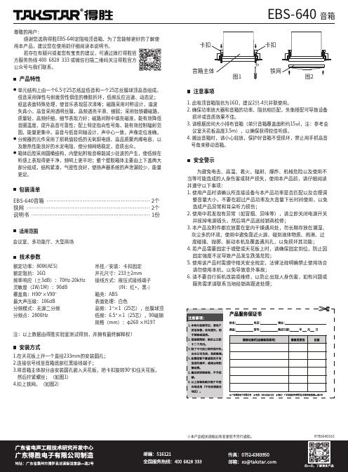
产品特性会议室、多功能厅、大型商场额定功率:80W(AES)额定阻抗:16Ω频率响应(±3dB):70Hz-20kHz 灵敏度(1W/1M):90dB 覆盖角:H90°×V90°最大声压级:106dB 分频模式:无源二分频分频点:2800Hz 注:以上数据由得胜实验室测试得到,并拥有最终解释权!吊挂/安装:卡扣固定开孔尺寸:233±2mm 接线方式:按压式接线端子 (IN:红+,黑-)箱壳:ABS表面处理:白色高频:1″×1(25芯),丝膜球顶低频:6.5″×1(25芯),90磁钢规格(mm):φ260 ×H197为避免电击、高温、着火、辐射、爆炸、机械危险以及使用不当等可能造成的人身伤害或财产损失,使用本产品前,请仔细阅读并遵守以下事项:1. 使用产品时请确认所连接设备与本产品功率是否匹配以及合理调 整音量大小,不要在超过产品功率及大音量下长时间使用,以免 造成产品异常和耳朵听力损伤;2. 使用中若发现有异常(如冒烟、异味等),请立即关闭电源开关 并拔掉电源插头,然后将产品送经销商检修;3. 本产品及附件都应放置在室内干燥通风处,勿长期存放在潮湿、 灰尘多的环境,使用中避免靠近火源、碰到液体物质、雨淋、过 度碰撞、抛掷、振动本机及覆盖通风孔,以免损坏其功能;4. 若产品需要固定于墙壁或天花板上时,请确保固定到位,防止因 固定强度不足导致产品发生跌落危险;5. 使用该产品时需遵守相关安全规定,法律法规明确禁止使用场合 请勿使用本机,以免导致意外事故;6. 请不要自行拆机改装或维修,以防止出现人身伤害,如有问题或 服务需求请联系当地经销商跟进处理;安全警示适用范围 技术参数安装方式●●●包装清单��������������������������������������������������������������������9TBS640S1C※本产品相关规格如有变更恕不另行通知。
上海精密科学仪器 FP640 火焰光度计 说明书

FP640火焰光度计使用说明书目录1 仪器简介 (1)1.1原理简述 (1)1.2主要特点 (1)1.3正常工作条件 (1)1.4使用领域 (1)1.5仪器成套性 (1)2 技术指标 (1)2.1稳定性 (1)2.2重复性 (2)2.3线性误差 (2)2.4检测限 (2)2.5响应时间............................................................................................................................................. .2 2.6样品吸喷量....................................................................................................................................... (2)3仪器结构 (2)3.1雾化系统 (3)3.2燃气系统 (3)3.3测量装置............................................................................................................................................. .3 4安装调试.. (4)4.1安装................................................................................................................................................... . (4)4.2调试...................................................................................................................................................... .4 5仪器操作.. (5)5.1屏幕说明 (5)5.2操作说明 (5)6 实例操作及计算 (6)6.1标准溶液 (6)6.2操作…………………………………………………………………………………………………………………………………… .66.3计算…………………………………………………………………………………………………………………………………… .67 三种母液的配制 (7)7.1以mmol/L为单位的钾、钠标准母液 (7)7.2以mg/mL为单位的氧化钾、氧化钠标准母液...................................................................... .7 7.3以ug/mL为单位的钾、钠标准母液. (7)7.4 mmol/L和ug/mL的换算............................................................................................................... (8)8注意事项 (8)9保养维护 (8)9.1空气压缩机 (8)9.2空气过滤器减压阀的排水方法 (8)9.3清洗 (8)10故障排除 (8)制造计量器具许可证编号:沪制1040048 产 品 执 行 标 准 编号:Q/YXLZ8-20091仪器简介1.1原理简述火焰光度计是一发射光谱为基本原理的一种分析仪器,它利用火焰本身提供的热能,激发碱土金属中的部分原子,使这些原子吸收能量后跃迁至上一个能量级,当它回落到正常能量级时,就要释放能量,这个释放的能量具有光谱特征,即在一定的波长范围。
示波器说明

功耗:约40VA
工作环境:
室内使用
海拔2000m; 满足 性能指 标温度 :10°C~35°C 最大工作范围:0°C~40°C 相对湿度:≤75% RH,干燥 机 械 尺 寸 : 310×150×455(mm)
重 量:约8kg 存 贮 温 度 :- 10°C~70°C
辅件:
THE INSTR UM ENT BEFORE REPLACIN G THE FUSE
35 34
! WARNING
TO AV OI D E LECTRIC SH OCK THE POWER CORD PR OTECTIVE GROUNDING COND UCTOR MUS T B E CONNE CT ED TO GROUND . FO R CONTI NUE D FIRE PRO TECTI ON. R EPLAC E ONLY WITH SPE CIFIED TY PE AN D RATED FU SE . NO OPERATOR SE RV ICE ABLE COMPONENT S INSIDE. DO NOT REMOVE COVE RS. REFE R SERVIC ING TO QUALIFIED P ERSON NE L.
2 ~4 0M Hz : 2. 5D IV
发
触发模式
AUTO:自动 当没有触发信号输入时,扫描工作在自由模式下 (适用于频率大于25H z的重复信号)
NORM:常态 当没有触发 信号时,踪迹处在待命状态并不显示. 电 视 场: 当想 要 观察 一 场的 电 视信 号时.
电 视 行: 当想 要 观察 一 行的 电 视信 号时
CH 2 INV AC
GND DC
.2 V .5
斯同瑞 SDT640-SP(K) 导轨式免拆线 三相多功能表 操作指南说明书
SDT640-SP(K)导轨式免拆线三相多功能表EN50022EN61036上海斯同瑞电气科技有限公司版本号: 1709手 册 目 录1. 简介.....................................................1.2. 功能介绍 ...............................................1.3. 技术指标 ...............................................1.4. 安装和尺寸 ............................................2.4.1 外形尺寸...........................................2.4.2 安装 ................................................2.5. 接线.....................................................2.6. 显示菜单 ...............................................4.7. 调试设置 ...............................................5.8. Modbus 通信协议 ..................................6.8.1 通信地址表 ........................................6.8.2 端口 ................................................7.8.3 协议 ................................................7.8.4 通信举例 ...........................................8.9. 常见问题 .............................................. 9.版权声明:本手册版权属于上海斯同瑞电气科技有限公司所有,未经本公司书面许可,任何人不得对此说明书和其中所包含的任何资料进行复制、拷贝或翻译成其它语言。
PSL640使用说明书V1.40
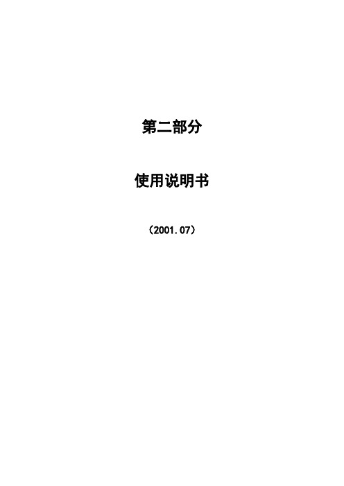
显示说明:
测量Ia,测量Ic分别为专用测量CTIac,Icc的电流值,测量Ib无模拟量输入,故显示为0;
测量Ua,Ub,Uc与保护电压Ua,Ub,Uc的输入端子相同,但数据取自专用测量模件;COSΦ为Uc、Ic的余弦值;
有功功率P也取自专用测量模件,但电压Ua、Ub、Uc不能太低,应大于额定电压的一半以上;
2.2.3
2.2.3.1
进入本菜单后MMI每隔3秒定时刷新模拟量通道的有效值和相角。
用“∧”键和“∨”键翻行,“+”键和“-”键翻页,可观察各模拟量通道的有效值和相角。
2.2.3.2
进入本菜单后MMI每隔3秒定时刷新各测量值的大小。
用“∧”键和“∨”键翻行,“+”键和“-”键翻页,可观察各测量量的大小。
修改完毕后,按【←┘】键确认操作。若要放弃修改,按“Q”键,系统将放弃本次修改操作并返回定值修改主菜单。
确认全部修改完毕后,按【←┘】键进行固化操作。若要放弃修改,按“Q”键,系统将放弃本次修改操作并返回上一级菜单。
在进行固化操作前,系统将提示选择目标固化区。通过选择固化的目标定值区,可完成对某一定值区的修改或对某一定值区的复制。
报告显示格式
此时按【←┘】键提示是否打印事故报告
3秒内按【←┘】键打印该份事故报告,否则退出打印画面,如果打印完成提示
如果打印机或通讯有故障,则提示
2.2.4.2
如果系统中有录波报告,将会显示录波报告浏览窗口,用“+”键和“-”键查看上一份或下一份报告,按【←┘】打印选定的录波报告
录波报告选择
2.2.5
考虑到不同运行方式的需要,本装置对传统的接线方式仍保留了接入端。例如,设置X6-10(手动跳闸入)、X6-11(跳闸入)、X6-13(合闸入)端子后,以跳合闸重动触点输出(X5-2,X5-3)作为保护跳、合闸中间出口,经外部跳合闸出口压板后分别接至跳、合闸操作回路的入口,即可实现传统接线方式。注意此时需把装置面板上的跳闸及合闸出口压板打至退出位置。装置面板上的手动分、合闸操作把手的停用也只需断开面板控制电源输入(X6-8),外部装设的手动操作把手可由X6的相关端子接入本装置的操作回路。
testo 400 950 640 说明书

testo 400参考级多功能测量仪testo 950参考级温度测量仪testo 650参考级湿度测量仪操作手册V2.02目录页码简介 (3)仪器的初始操作 (4)仪器介绍 (6)功能区 (8)菜单概览/配置 (9)功能键分配方案 (10)打印机初始化操作一体化打印机0554.0570 (12)德图打印机0554.0545 (14)仪器出错信息 (15)仪器复位数据 (16)数据管理 (17)操作条码 (18)测量任务示例温度测量 (19)湿度测量 (24)Aw值测量 (28)自动保存 (30)风速测量 (37)WBGT测量 (44)NET测量 (45)压力测量 (46)转速测量 (46)电流/电压测量 (47)大气压测量 (48)泄露检测探头 (49)CO/CO2测量 (50)电源 (51)软盘升级 (52)技术资料 (53)仪器符合89/336/EWG标准翻印版权Testo GmbH&Co.testo 400产品以内的软件和软件结构均受全球版权条例的保障!亲爱的用户:购买德图测量仪器一定是您正确的选择,每年都有数以千计的用户购买我们的高质量产品。
这种情况源于以下原因:1)性能-价格比。
价格合理而且性能可靠。
2)根据不同的仪器,我们的保修期可延长至3年。
3)基于40多年的专业仪器制造经验,我们能够针对您的测量任务提出理想的解决方案。
4)ISO 9001质量认证保证了我们产品的质量。
5)我们的产品根据EU的要求贴有CE标志。
6)所有相关参数都附有标定证书并在当地提供标定服务,举办各种培训会以及提供技术咨询。
7)完善的售后服务。
您所购买的仪器是一种高度灵活的、可升级的测量系统。
他们的测量范围及应用软件可随不同的安装方式而变化。
打开仪器后,您立刻就会得到有关仪器类型、编号以及本仪器中使用的软件版本等信息。
其他相关信息如售后服务等资料可通过打印机得到(见16页)。
本手册将给出testo 400、testo 650 和testo 950最大的工作范围。
RCU640 遥控器用户手册说明书
ENUser manualRCU640 Remote ControlUnit1IntroductionSafety Information● If device is moved from warmer place to a colder one some problem might occur. Please switch off the receiver and turn it on after 1 or 2 hours.● Don’t put any objects on the device.● The product purchased is a sophisticated electronic device which is not suitable for children under 18 years.● We do not assume responsibility for dam-ages caused to people or object, deriving from use of the device made by people under 18 years.give a warranty regarding the contents of this User Manual and waives any implied warranties regarding market value or fitness for specific purposes. The information contained herein provide guidelines allowing the operation and maintenance of the receiver.Ferguson reserves the right to make changes, corrections or to translate the User Manual without giving prior notice of such changes. Therefore, it is recommended that users visit our website regularly to receive the latest information.RCU640Setup TV via brand name code1. Switch on the TV for which you wish to use the remote control.2. Find the code number of your TV brand in the code list (e.g. LG 0075; 0082; 0083; …).3. Press TV button for three seconds The POWER button on your remote control lights up, i.e. RCU640 is in set-up mode.4. You now have to enter the 4-digit device code (e.g. 0075 for LG TV set). If an entry does not occur within 15 seconds, the set-up mode is automatically terminated.5. The POWER button LED goes out if the remote control accepts the code.If the POWER button LED flashes twice the code is incorrect; and you need to start from step 2.If this occurs, re-enter the correct code from the list.6. Check the function of the buttons on your remote control. If the majority of the buttons on your new remote control do not function correctly, enter another 4-digit device code (e.g. 0082…) from the list under the same brand name. Repeat steps 3 to 6 until all the basic functions operate correctly. The TV is set up correctly as soon as you enter the correct code. NOTE:Exit the set-up mode by pressing the TV button or OK button. The set-upmode is automatically terminated if a button is not pressed during a 15 second period.NOTE:After entering the state of setup, ONLY the numeric keyboard, OK, POWER and TV button can work accordingly, the other buttons do not have response when you press them.Setup TV via auto searchIf the set up via brand name and code was not successful or you were unable to find your brand name in the list, you can use the auto search function to find the correct TV code for your remote control.1. Switch on the TV for which you wish to use the remote control.2. Point the remote control at the TV. Press and hold down the the TV button for 3 seconds, (or just press TV button for three seconds). The POWER button should start to flash, i.e. the RCU640 is in Auto Search mode.3. Press MUTE button and then release, the OFF signal is automatically transmitted from the remote control to the TV (code scan). As soon as the TV switches off, immediately press OK button or TV button to terminate Auto Search, now the POWER button LED light goes out.4. Switch on the TV via the POWER button. Check whether the other buttons on your remote control function correctly. If none of the buttons function (i.e. the search was not be stopped at the correct time) or the majority of the buttons do not function correctly, restart the search (see steps 3 to 4) to find a suitable code. If the majority of the buttons function correctly, set up has been successful. Re-press the TV button to save the code and to terminate the set-up mode. NOTE:After entering the state of setup, ONLY the MUTE, OK, LEFT, RIGHT and TV button can work accordingly, the other buttons did not have response when you press them.NOTE: Entering the auto searching mode, it will search backward from the current code backwards ,but you can press LEFT (forward) or RIGHT (backward) to change Search direction.NOTE:After all codes have been gone through, The POWER button will flash three times and go off. The RCU640 exit from auto search automatically.23RCU640Setup TV via manual search1. Switch on the TV for which you wish to use the remote control.2. Point the remote control at the TV. Press and hold down the TV button. (or just press TV button for three seconds). Then release the button.3. The POWER button lights up and the remote control is in set-up mode.4. Press the POWER button approx. every 1.5 seconds. The device should start to flash, i.e. the device is in Manual Search mode.5. As soon as the TV switches off (or is reac-tive), press OK or TV button to save the codes and exit from Manual Search mode, now the POWER button light goes off.6. Check whether the other buttons on the remote control function correctly. If the majority of the buttons do not function correctly, press the POWER button approx. every 1.5 seconds to initiate the reactive code (manual search is continued, see steps 4 to 5).NOTE: The Manual Search is automatically terminated if no entry occurs during a 15 second period.NOTE: After entering the state of setup, ONLY the POWER, OK, LEFT and RIGHT button, and TV button can work accordingly, the other buttons did not have response when you press them.NOTE: Entering the manual searching mode, it will search backward from the current code backwards, but you can press LEFT (forward) or RIGHT (backward) to change Search direction1. Press and hold down the TV button simultaneously press number button 1 to display the thousands of the 4-digit code. Count how often the POWER button flashes. If the POWER button does not flash, the number is ZERO.2. Press and hold down the TV button simultaneously press number button 2 to display the hundreds of the 4-digit code.3. Press and hold down the TV button simultaneously press number btutton 3 to display the tens of the 4-digit code.4. Press and hold down the TV button simultaneously press number button 4 to display the ones of the 4-digit code.Example for code 0075:1. Press TV and 1 LED flashes Zero times.2. Press TV and 2 LED flashes Zero times.3. Press TV and 3 LED flashes Seven times.4. Press TV and 4 LED flashes Five times.Reset / delete function1. Press TV button for three seconds the POWER button on your remote control lights up.2. You now have to enter the 4-digit device code 9990.All the set-up data and commands for TV in the remote control are deleted and the POWER button light goes off.RCU640RCU64056RCU640RCU6407RCU640RCU640910RCU640RCU64011www.ferguson-digital.euv1.21。
海德漢TNC 640使用手冊说明书
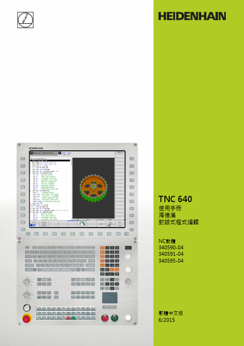
TNC的控制器TNC的控制器視覺顯示單元上的按鍵按鍵功能選擇分割畫面配置在加工模式與程式編輯模式之間切換顯示用於選擇螢幕上功能的軟鍵在軟鍵列之間切換文字數字鍵盤按鍵功能檔案名稱,註解DIN/ISO 程式編輯機械操作模式按鍵功能手動操作電子手輪使用手動資料輸入定位程式執行,單一單節程式執行,完整序列程式編輯模式按鍵功能程式編輯程式模擬程式/檔案管理,TNC功能按鍵功能選擇或刪除程式與檔案,外部資料傳輸定義程式呼叫,選擇工件原點及加工點表格選擇MOD功能顯示NC錯誤訊息的說明文字,呼叫TNCguide顯示所有目前錯誤訊息顯示計算器導覽鍵按鍵功能移動反白直接進入單節、循環程式及參數功能進給率與主軸轉速的電位計進給速率主軸轉速循環程式、子程式及程式段落重複按鍵功能定義接觸式探針循環程式定義與呼叫循環程式對於子程式編輯及程式段落重複進行輸入及呼叫標籤在程式內輸入程式停止符號刀具功能按鍵功能在程式內定義刀具資料呼叫刀具資料程式編輯路徑移動按鍵功能接近/離開輪廓FK 自由輪廓程式編輯直線極座標的圓心/極點利用圓心做圓弧加工具有半徑的圓含切線連接的圓弧切角/角落圓角特殊功能按鍵功能顯示特殊功能選擇格式內下一個標籤上/下一個對話方塊或按鈕輸入並編輯座標軸與數字按鍵功能. . .選擇座標軸或在程式當中輸入. . .數字小數點/倒反代數符號使用極座標輸入/增量值Q參數程式編輯/Q參數狀態儲存來自計算機的實際位置或數值NO ENT忽略對話問題,刪除字元確認輸入與重新對話總結單節,並離開輸入清除數字輸入或TNC錯誤訊息停止對話、刪除程式段落TNC的控制器基本原則有關本手冊有關本手冊本手冊內使用的符號說明如下。
要進行任何變更,或發現任何錯誤?我們持續努力改善我們的文件, 請將您的問題傳送至下列電子郵件位址: *************************。
TNC機型、軟體與特性TNC機型、軟體與特性此手冊說明由TNC搭配以下NC之軟體編號所包含的功能及特性。
Plantronics Discovery 640 Bluetooth Headset用户手册说明书
USER GUIDE_DISCOVERY™640BLUETOOTH® HEADSETWELCOME 2CONNECTING 4CHARGING5POWERING ON AND OFF67• Look in your Bluetooth device manual for the section that describes how to set up a Bluetooth wireless connection.• Move through the menu selections on your phone until the phone display shows “Look for Devices”, or equivalent, as a selection.1. With your Headset turned off, hold down the Call Control Button until the Headset Status Indicator briefly glows blue, then flashes red and blue. The Headset is now in discovery mode and will stay that way for 30 seconds.2. On your phone, highlight and select “Look for Devices”, or equivalent, to activate the scan for the Headset.3. When the phone display shows the scan results, select “640 Plantronics”. The phone will continue to search for the Headset.4. When the phone display asks for a passkey, type “0000” and press Enter.Your Headset is now linked to your phone.USING MUL TIPOINT (MORE THAN ONEBLUETOOTH DEVICE)Plantronics Discovery 640 supports Multipoint technology, which permits simultaneousconnections with two different Bluetooth audio devices. To pair another Bluetooth device: repeat the previous pairing steps with the new device.TO PAIR ANOTHER BLUETOOTH DEVICE Repeat the previous pairing steps with the new device.INITIATE A CALL The headset will assume you wish to initiate a call on the device recently used.In most cases, the ring tone from thedevice will transfer through to the headset, allowing the user to determine whichdevice is ringing. In some cases, however, the headset will apply a ring tone to the incoming call. In either case, the user may be able to determine which device is ringing by the distinct ring tone. To answer the call, press the Call Control Button.TO ANSWER A CALL ON ONE DEVICE WHILE TALKING ON THE OTHER There is no capability for placing one call on hold while answering another . Therefore, to answer the second call, the first call must be terminated.Terminate the first call by pressing the call control button once.Wait for the beep and then answer the second call by pressing the Call Control Button again. If you choose not to answer the second call, and you have voice mail on the second device, the call will go to voice mail.8The Headset comes with 3 Soft Gel Ear Tips and an Optional Ear Stabiliser . The medium-sized Ear Tip is installed for wearing on the right ear .1. Twist the Ear Tip to the right for wearing on the left ear .2. Place the Headset into your ear with the elongated side of the Ear Tip pointing up and forward.If the fit is not comfortable, either too tight or too loose, remove the Ear Tip from the Headset by turning the Ear Tip to the neutral* position and pulling the Ear Tip away from the Headset.1. Select the Ear Tip size that fits most comfortably in your ear.2. Hold the Ear Tip with the elongated edge pointing down and push the Ear Tip post into the opening on the Headset.3. Twist the Ear Tip to the left for wearing on the right ear or to the right for wearing on the left ear .4. Place the Headset into your ear with the elongated side pointing up and forward.The Ear Tip Stabiliser may be attached to the Headset to improve stability.1. Remove the Ear Tip from the Headset by turning the Ear Tip to the neutral position* and pulling the Ear Tip away from the Headset.2. Attach the Stabiliser in-between the Ear Tip and the Headset.3. Replace the Ear Tip.9ANSWERING AND USING THE MUTETo turn the mute on while on a call, press both sides of the Volume/Mute Button simultaneously until you hear a beep.To turn the mute off, press both buttons again.MOVING OUT OF RANGEAs the Headset is moved away from the mobile phone or Bluetooth device,• Audio quality will be impaired• A beep will be heard in the Headset • Only the Power Off function will operate After 30 seconds, the Headset will make one attempt to reconnect to the phone or device.LAST NUMBER REDIALTo activate last number redial, double click the call control button. You will hear a high tone for each key press.USING VOICE RECOGNITIONHEADSET STATUS HEADSET STATUS INDICATORPowering on Blue light appears and flashes every 6 secondsPower on Blue light flashes every 6 secondsPowering off Red light appears and goes offPower off Indicator is not litCharging battery Red light is onBattery fully charged Red light is offDiscovery mode Indicator flashes blue and red for 30 secondsMissed call Infrequent flashing blue/redPress any button to cancelRinging Rapid flashing blue/redOn-Line Indicator (OLI)Blue flash every 10 secondsLow battery Flashes red10TROUBLESHOOTINGPOSSIBLE CAUSE SOLUTIONYour phone did not locate the Headset.Repeat the Pairing process on page 7.Incorrect menu selections weremade on your mobile phone.Repeat the Pairing process on page 7.POSSIBLE CAUSE SOLUTIONMute is turned on.Press both sides of theVolume/Mute Button simultaneously. CALLERS CANNOT HEAR ME.POSSIBLE CAUSE SOLUTIONThe Headset is not turned on.Press the Call Control Button for 2 seconds until you heara beep or see the Headset Status Indicator glow blue.Your Headset is out of range.Move the Headset closerto the phone or Bluetooth device.Your Headset battery is flat.Charge your battery using the AC Power Adapter supplied, the AC Adapter from your mobile phone,or a AAA battery.The listening volume is too low.Press the top part of the Volume/Mute Buttonto increase the sound heard in the Headset.I CANNOT HEAR CALLER/DIALLING TONE.1112TO ORDERPlease contact your Plantronicssupplier, Plantronics Technical Assistance, or go to .ONLINE PRODUCT TECHNICAL131415Plantronics Ltd, Interface Business Park, Bincknoll Lane, Wootton Bassett, Wiltshire SN4 8QQ. ENGLAND © 2005 Plantronics, Inc. All rights reserved. Plantronics, the logo design, Plantronics Discovery and Sound Innovation are trademarks or registered trademarks of Plantronics, Inc. The Bluetooth name and the Bluetooth trademarks are owned by Bluetooth SIG, Inc. and are used by Plantronics, Inc. under licence. All other trademarks are the property of their respective owners. Patents U.S. 5,210,791; Patents Pending. Printed in U.S.A. 69327-04 (08/05)Plantronics Ltd.Interface Business Park Bincknoll Lane Wootton BassettWiltshire SN4 8QQ, ENGLAND Tel: 0800 410014+44 (0)1793 842200Fax: +44.1793.848.853Plantronics Pty Ltd.5 Everage Street Moonee PondsVictoria 3039, Australia Tel: 61.3.8371.0050Fax: 61.3.9326.1620。
25LC640中文翻译资料

25LC640中文翻译资料山东泰开自动化李凯设备选择表(25AA640 25C640 )64K SPI 总线串口EEPROM:封装类型:方块图特征:●低功率COMS工艺-写电流:3mA标准-读电流:500u标准-待机电流:500nA标准●8192×8位组织●32字节页●写周期时间:5mA最大●自动同步擦除和写入周期●块写入保护-未保护,1/4,1/2,或全部数组●内置的写保护-电源开/关数据保护电路-写允许锁存器-写保护管脚●连续读●高可靠性-耐久度:1M周期(可保证的)-数据保持:大于200年-静电防护:大于4000V●8脚PDIP,SOPC,和TSSOP封装●温度范围支持;-商业级:(C) 0℃至 +70℃-工业级:(I) -40℃至 +85℃-汽车级:(E) -40℃至 +125℃说明:美国微芯科技公司的25AA640/25LC640/25C640(25XX640)是64K比特电可擦除PROM。
这个存储器的使用通道是简单串行外围接口(SPI)兼容串行总线。
这个总线信号需要时钟输入(SCK)加单独数据在(SI)和数据输出(SO)连线。
进入装置的控制是通过芯片选择(CS)输入。
通信到装置能够暂停通道保持管脚(HOLD)。
虽然装置是暂停,转变在输入将是忽略,除了志片的选择,允许主动服务较高优先级的中断。
1.0电气特性图形1-1: AC 测试电路1.1 最大等级Vcc .................................7.0V全部输入和输出w.r.t.Vss...-0.6至Vcc+1.0V储存温度.....................-65℃至150℃引线的焊接温度(10秒) (300)静电保护在全部管脚...................4kV注意:强调以上这些列出关于“最大等级”可能引出永久损伤到设备。
这强调的等级仅和设备的功能操作,而且那些或任何其它的条件超出那些声明在说明书的操作表中是未隐含的。
Fluke 640B Infrared Thermometer说明书
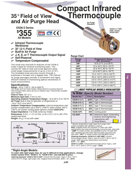
Operating Ambient Temperature Range: -18 to 85°C (0 to 185°F) Air Purge: Built-in flow for operation at temperatures of -18 to 116°C (0 to 240°F)
OS36-2-J-(*) OS36-2-K-(*)
Temperature Range (2% Accuracy)
The small size and built-in features of the OS36-2 make it ideal for infrared monitoring tasks. The
50F
-18 to 27°C (0 to 80°F)
Compact Infrared
35° Field of View
Thermocouple
and Air Purge Head
Air Purge Standard.
OS36-2 Series
$355
OS36-2-J-140F, $355, shown actual size.
All Models
ߜ Infrared Thermocouple
140F
25 to 80°C (80 to 180°F)
180F
70 to 104°C (160 to 220°F)
240F
95 to 130°C (200 to 270°F)
J
efficient method of maintaining optical cleanliness in
280F
125 to 155°C (260 to 310°F)
harsh environments.
爱因斯坦e640 说明书

Every decade or two a quantum leap occurs in ideas and technology that sets the stage for years to come. While most are content to follow the leader and add a feature or two, a few innovators take the lead with revolutionary advancements that redefine the future state of the art.Paul C. Buff, Inc.™ has a track record for such innovations, first in 1986 with the forerunner of the modern self-contained studio flash – White Lightning™ Ultra. Then again in 2001 with the first full featured affordable-yet-professional monolight for the new masses of young digital photographers – the colorful little light that could – and did – AlienBees™.We are now pleased to present the most advanced integrated studio flash system ever conceived – at any price, with performance and features far beyond any “Professional” monolight. After two years of intense design, evolution, blood, sweat, and tears, welcome to the brave new future of studio lighting - Einstein™, and the companion Cyber Commander™ extreme integrated wireless control system. Proudly designed and manufactured in America.EINSTEIN TMOperating Instructions for Einstein TM 640 Studio FlashPaul C. Buff, Inc.TM • 2725 Bransford Ave • Nashville, TN • 37204 • USA1-800-443-5542 • 615-383-3982 • v. 04/2012Paul C. Buff, Inc.TM USA offers a 60-Day Absolute Satisfaction Guarantee. If, for any reason, you are not satisfied with the equipment that you have purchased from Paul C. Buff, Inc.TM USA, you may return your equipment within 60 days for a complete refund minus the cost of shipping.Paul C. Buff, Inc.TM USA additionally offers a 2-Year Factory Warranty on all Einstein TM 640 flash units. The obligation of Paul C. Buff, Inc.TM is limited to the repair or replacement of products that have become defective under normal use, as outlined in the manual. The warranty does not apply to the flashtubes or modeling lamps as these become exhausted based on normal use (except in the unusual case of an unexpected manufacturer’s defect). Should you experience any difficulties, please contact us so that we can assess your predicament and let you know if we need to bring in your unit for repair.INITIAL SETUP: The Einstein™ flash unit ships with a black polycarbonate shipping cover, in place over the flashtube and modeling lamp to protect these items in transit. The opaqueblack cover must be removed before using the unit.Locate the Frosted Glass Dome (inside the box, packaged separately from the flash unit).Place the dome on the faceplate of Einstein TM by sliding the outer lip under the Spring Clipsone side at a time. If the fit feels loose, you may push in on the spring clips towards theflashtube (be careful not to touch the flashtube), then re-attach the dome.Place Einstein™ on a standard light stand (with 5/8” top coupler) inside the Stand Mountand secure with the Tightening Knob . Loosen the Swivel Ratchet Handle to allowswiveling Einstein™ up or down. Note the handle has a ratchet action. Pulling the handleout from Einstein™ allows you to position it so that it doesn’t run into the body of the unitwhen tightened.Connect the supplied power cord into the Power Socket , and into a 120V or 240VAC,50 or 60Hz outlet, or to Vagabond™. Einstein™ will automatically sense the voltage andfrequency. Press the Power Button to turn the unit on. Note that when Einstein™ is turnedOFF it’s actually in STANDBY Mode and can be turned ON remotely if it is fitted with theoptional CSXCV Transceiver and Cyber Commander™ remote.EASY SET USE: The recessed Easy Set Button allows instant setup for most users. Pressing this button clears any special programming and sets Einstein™ to the followingparameters (how the unit is shipped, with any programming cleared):1. Modeling lamp tracks flashpower. The Einstein ™ has “What You See Is What You Get”modeling. Recycle indication is provided by an audible beep and by the modeling lampdimming then restoring brightness.2. Einstein™ is placed in Constant Color Mode , the Slave Flash Sensor is turned on, andthe optional CSXCV Transceiver is set to Frequency 1 and Channel 1, if present.PRELIMINARY TESTING: With Einstein™ on, operating the Adjust Buttons should increase or decrease both the flashpower and the modeling brightness by 1/10 f-stop perclick. If you hold either button in, the power will scroll.DISPLAY FUNCTION: As you adjust the power using the Adjust Buttons, you should see the Flash and Model Bargraphs on the LCD display go up or down correspondingly. SinceEasy Set defaults the modeling lamp to track the flash power, both bars should move in2E640 with shipping coverin placeEasy Set Button Adjust Buttons CSXCV Transceiver (sold separately)Umbrella HolderSlave Flash SensorMicro SD Card SlotFunction ButtonAdjust Up/Down Buttons8A FusePower ButtonPower Cord SocketTest ButtonEasy Set ButtonSync Jack (1/8-inch)Quick-Release LeversSwivel Ratchet HandleStand MountTightening KnobFrosted Glass DomeSpring ClipsHolding FingersFlashpower Bargraph (Full to 1/256 power)Modeling Lamp Bargraph (0 to -8f)Flash Adjustment ScreenModel Adjustment ScreenModel Lamp Mode ScreenFull Power ON Tracks FlashpowerIndependently Adjustable Off OFFRecycle / Ready Indicator ScreenAudible Indicator Visual IndicatorBoth Neither OFFSlave Eye Status Screen (slave on or off)Action / Color Mode ScreenRemote Channel (channel 01 - 16)Remote Frequency(frequency 01 - 16)unison. If you press the Test Button at any power, the unit should flash and the modelinglamp should dim. Then, when the unit is recycled, the modeling lamp will return on and theaudible recycle indicator beep will sound.The same should happen if the Sync Jack is connected to your camera via sync cord toyour camera’s PC jack or Hot Shoe Adapter (see Camera Sync , page 8; see also Cyber-Sync TM / Cyber Commander™ Radio Remote ).DEFAULT-TO-FLASH SCREEN: Einstein™ defaults automatically to the Flash Adjust-ment Screen after a few seconds following any setup changes; this is the screen with the flash icon, highlighted in blue in the LCD screen diagram example (above). Power adjust-ment is performed by operating the Adjust Buttons. Notice as you change the flashpowerwith these buttons, the blue-highlighted screen will display the current flashpower relativeto Full Power (-1.0f in this example), the color temperature (5725K in this example), the t.1flash duration (1/2050 second in this example), the EU Number (5.7 in this example), andthe WS (320WS in this example).Since the modeling lamp was set to track the flashpower by the Easy Set Button, the ModelAdjustment Screen will also change (-1.0f and 125W in this example).ATTACHING LIGHT MODIFIERS: Light modifiers may be attached to Einstein™ via two mechanisms: the Umbrella Holder or the front Reflector / Softbox Attachment Mechanism -the Holding Fingers and Quick-Release Levers . The umbrella tube runs the entire lengthof the top of the unit. It holds standard umbrella shafts up to 0.350” diameter, accommodat-ing shafts 9mm and smaller. The Umbrella Holder tightening knob secures the umbrella inthe desired position. Reflectors, softboxes and similar accessories use the standard AB /WL / Balcar mount, and are held securely by the Holding Fingers. Quick-Release Leversare spring loaded and accessible from either side of the unit. Einstein™ mounts all acces-sories that fit previous Paul C. Buff, Inc.™ lights except the obsolete WL130, WL5,000 andWL10,000 models. When mounting accessories to the face plate, be sure all four HoldingFingers are within the opening and that the Quick-Release Levers have returned firmly tothe open position. Failure to do so can result in the unintended release of the modifier fromthe light.MICRO SD CARD SLOT: Firmware updates can be downloaded and installed via a standard Micro SD Card plugged into this slot.3Flash (left) and Modeling(right) Bargraphs Flash Adjustment screenNAVIGATING EINSTEIN™ PARAMETERS: With the Easy Set Button, most simple Einstein™ shoots are plug-and-play, not requiring parameter adjustments other than flashpower. But for more advanced shoots, all parameters may be easily manipulated. The display automatically defaults to the Flash Screen , identified by the blue background color in the LCD screen example (on the previous page), where adjustments begin. The Flash and Modeling Bargraphs are always present and indicate the power, relative to Full Power, in 1/10f increments. As adjustments are made, the digital parameters in the Flash and ModelAdjustment Screens will update. To navigate the adjustment screens, pressing the FunctionButton will sequence through all the screens. The currently active screen background will turn blue. If no adjustments are made to the active screen for 10 seconds, the display willrevert to the default state with the Flash Adjustment screen active.Flash Adjustment Screen (default): Adjust Buttons raise or lower flashpower at 1/10f per click. Holding either button scrolls flashpower up or down. At any flashpower setting, thedigital numerical display in the screen and the left Flash Bargraph indicate all flash data. Ifthe model lamp is set to Tracking , the numerical model data and the right Model Bargraphwill also change.Model Mode Screen: When this screen is active, you may select between four modeling lamp modes by pressing the Adjust Buttons: On (Full Power), Independently Adjustable,Track Flashpower and Off . When the modeling lamp is set to Track , there is a provisionin the Model Adjustment Screen to offset the modeling lamp brightness such that fullflashpower (640WS) results in a modeling brightness other than the default 250W. Thisfeature is useful when Einstein™ is used with other monolights and it is desirable tomaintain a constant ratio of model brightness to flashpower for accurate modeling previews.For example, if an Einstein™ is used in a mixed system containing AlienBees™ B1600units (640WS) with 150W lamps, it would be advantageous to set the Einstein™ suchthat its model lamp also produces 150W when it is set to 640WS (see Model AdjustmentScreen).Model Adjustment Screen: Selecting this screen allows modeling lamp adjustment in either the Independent Adjustment mode or Tracking mode. In the Independent Adjustmentmode, the Adjust Buttons may be used to raise or lower the modeling brightness. Thedigital display of watts and f-brightness relative to full 250W will update. In the Trackingmode, operating the Adjust Buttons introduces an offset between flashpower and modelingintensity. The bargraphs will still move in unison, but with an offset between the bars.Recycle / Ready Indicator Screen: In this screen, recycle indication can be set to Audible, Visual , Both or Neither via the Adjust Buttons. In the Visual mode, the lamp dims as theunit recycles and restores when ready. In the Audible mode, a beep sounds when recycleis complete; the modeling lamp does not dim as this might be disconcerting to models.When the flashpower is lowered, Einstein™ automatically rapidly dumps excess capacitorvoltage. The screen turns red during dump and back to green when dump is complete.Slave Eye Status Screen: The slave is turned on or off using the Adjust Buttons. When on, the slave eye is still active whether or not the sync jack is in use.Remote Channel and Frequency: These screens set the channel and frequency of the optional CSXCV Transceiver, if present, via the Adjust Buttons. If the optional Cyber Commander™ is used, each light in the studio must be set to the same frequency as the Cyber Commander™ and each light must be set to a different channel. The Cyber Commander™ allows you to capture, control and display every parameter of Einstein™ remotely, including remote power down (please see the Cyber Commander™ manual for complete information). If only the CST Trigger Transmitter is used, without the Cyber Commander™, all lights on the same frequency as the CST will fire regardless of channel selection.Action / Color Screen: Most users will set this mode to Color Mode – reserving Action4Model Mode screenModel Adjustment screen Recycle / ReadyIndicator screenSlave Eye Status screenRemote Channel screenRemote Frequency screenAction / ColorMode screenCONSTANT COLOR MODE ACTION MODE5Mode for shooting where the fastest possible flash durations are desired and where constant color is a secondary consideration. The Adjust Buttons allow mode changing when the Action / Color Screen is active.IGBT ADVANTAGES: Even the most expensive Pro Monoflash units usually control flashpower by varying the voltage applied to the flash capacitors. This simple and inexpensive method has three distinct limitations to the achievement of truly professional performance:1. The range of power reduction is typically limited to 1/8 to 1/32 power, often resulting in an inability to achieve low aperture settings with close lighting techniques2. As power is reduced, the Flash Duration becomes longer - typically twice as long at minimum power relative to maximum power. The median t.1 flash duration of the ten most popular Pro monolights ranges from 1/200 second to 1/400 second – too slow for sharp freezing of action in sports, dance and other rapid movement shots (see graph, page 7)3. Color Temperature typically varies by 75 to 80K per f-stop of power reduction, resulting in about 400K color difference between minimum and maximum power. Einstein™ employs proprietary advanced digitally controlled IGBT technology to control flash power. This results in an extreme range of power reduction (1/256 power) in precise 1/10f stops. As power is reduced, the t.1 flash duration also decreases dramatically instead of increasing. This technology allows Einstein™ to maintain a constant color temperature throughout the entire 256:1 power range.Two operating modes are provided – Action Mode and Constant Color Mode . In Action Mode , the t.1 flash duration shortens rapidly from 1/588 seconds at Full power to 1/13,500 seconds at minimum power for incredible action freezing capability, but the color temperature increases as power is reduced. In Constant Color Mode , the t.1 flash duration drops less rapidly, to a minimum of 1/8000 second, while maintaining a constant color temperature of 5600K (+/- 50K) throughout the entire power range. The processor controls the accuracy and repeatability with very high precision (see graphs and specifications, pages 7 and 8).CONSTANT COLOR mode - the emitted color temperature is held constant at 5600K plus or minus 50K at any power setting or input voltage. At Full Power, the t.5 flash duration is 1/1600 second and the t.1 time is 1/540 second. As power is reduced to ½ power the color remains constant, while the flash duration decreases to approximately 1/1700 second t.1 (note that with IGBT control, the t.5 spec is no longer meaningful, so only the t.1 flash duration appears on the rear LCD display). As power is further decreased, the color temperature remains constant and the t.1 flash duration falls ultimately to 1/9,000 second at the lowest power settings.ACTION mode - the color temperature rises as power is reduced but the t.1 flash duration is minimized even further for maximum action stopping capability where absolute color consistency is secondary to motion freezing. At ½ power in Action Mode the t.1 flash duration is approximately 1/2000 second and the color temperature is approximately 5750K. Absolute values of flash duration and color temperature are indicated on the rear LCD display and are yet to be fully specified.EU NUMBERS: When lights with different WS ratings are mixed in a studio, terms like “1/4 power” or “-3f” don’t tell the user how much light one unit outputs compared to another. In order to allow a direct comparison between lights of different ratings, several European manufacturers have instituted a numbering system that directly compares lights in 1/10f increments without requiring calculations or WS math conversions.The EU Number defines a 6400WS power level as EU10.0, and each 1/10 f-stop change is represented by a one digit change in the decimal. Thus, EU9.9 is 1/10f less power than EU10.0. A full f-stop change is a one digit change before the decimal point. If your main light is EU6.4 and your fill is EU5.3, you quickly know your fill light is 1.1f less powerful than your main light.EU9.0 = 3200WS EU8.0 = 1600WS EU7.0 = 800WS EU6.0 = 400WSEU5.0 = 200WSEU4.0 = 100WSEU3.0 = 50WSEU2.0 = 25WSEU1.0 = 12.5WSEU0.0 = 6.25WSEU-1.0 = 3.13WSEU-2.0 = 1.56WSSETTING UP EINSTEIN TM WITH CYBER COMMANDER TM:Unlike setting up vintage Buff lights in Cyber Commander TM, it is not necessary to perform the tedious “Spec Lights” and “Light Settings” steps required by vintage lights that communicate via CSR+ or CSRB+ receivers. The Einstein TM / CSXCV combination allows all the Einstein TM back panel settings to automatically be transferred into Cyber Commander TM. Acquiring this information and recognizing Einstein TM units must be accomplished by using one of the methods detailed below.PLEASE NOTE:There are two instruction sets for setting up Einstein TM lights. The first set starts the set up process from scratch, erasing any programming already made in the Cyber Commander TM. Any information erased will have to be reprogrammed, including light specifications and names. To keep existing light information programmed in your Cyber Commander TM, please follow only the steps in the second section.For new set ups with no existing lights, or to start from scratch - This will erase any information already programmed! ing the function and arrow buttons of Einstein TM, ensure each unit is set to a channel not shared by any other light / CyberSync TM receiver, and set to the same frequency as your Cyber Commander TM.2. Enter the Cyber Commander TM set up menu by scrolling to the right with the right joystick.3. Using the right joystick, highlight and select OPEN MEMORY.4. Using the left joystick, select STUDIO in the lower left corner. Your screen should now read “OPEN ALL FROM STUDIO” in blue, followed by “SYNC CYBER COMMANDER FROM STUDIO LIGHTS” in white.5. Using the right joystick, press in. After a few seconds, “SYNC CYBER COMMANDER FINISHED OPENING” will appear in white.6. Einstein TM units are now defined as “Einstein 640” and the Cyber Commander TM is set to all parameters as they appear on the back panel of the light(s). No further action is required, but any changes that are desired should be performed via Cyber Commander TM, as any changes made to the light itself will be overridden and reverted back to the settings within the Cyber Commander TM.7. Any legacy lights (White Lightning TM, AlienBees TM, Zeus TM) will require the specification process as outlined in the Cyber Commander TM user manual.8. Any lights already programmed will have been erased and new programming will be required.To add one or more lights to a set up with existing lights - These steps will retain existing programming to your Cyber Commander TM.ing the function and arrow buttons of Einstein TM, ensure each unit is set to a channel not shared by any other light / CyberSync TM receiver, and set to the same frequency as your Cyber Commander TM.2. Enter the Cyber Commander TM setup menu by scrolling to the right with the right joystick.3. Using the right joystick, highlight and select OPEN MEMORY.4. Using the left joystick, select the CHANNEL (CH02, CHO3, etc.) to correspond to the Channel Number you have set on the new light you are about to recognize. By opening new lights individually, one light channel at a time, instead of OPEN FROM STUDIO, you will avoid losing any programming already performed for existing lights in a setup. Your screen should now read “OPEN CH(XX) FROM STUDIO” in blue, followed by “SYNC CYBER COMMANDER FROM STUDIO CHANNEL [XX]” in white.5. Using the right joystick, press in. Almost immediately, “SYNC CYBER COMMANDER FINISHED OPENING” will appear in white.6. Repeat steps 4 and 5 immediately above for each new light.7. Einstein TM units are now defined as “Einstein 640” and the Cyber Commander TM is set to all parameters as they appear on the back panel of the light(s). No further action is required, but any changes that are now desired should be performed via Cyber Commander TM, as any new changes made to the light itself will not be transferred to the Cyber Commander TM unless steps 4 and 5 above are repeated. (continued on next page)67CONVENTIONAL FLASH VS. EINSTEIN TM IGBT CONTROLFigure 2 Variable Voltage at 1/2 Power100%50%10%t.51/1600t.11/470Figure 4 IGBT Control at 1/2 Power100%50%10%t.11/2050Figure 3 IGBT Control at Full Power 100%50%10%t.11/588t.51/2000Figure 1 Variable Voltage at Full Power100%50%10%t.51/2000t.11/588Conventional Voltage Control: Figures 1 and 2 show the flash waveform from a conventional variable voltage monoflash. As power is reduced, both the t.5 and t.1 flash durations become longer as power is reduced. Note that even beyond the t.1 point the flash continues to trail off slowly, adding motion blur. The color temperature drops as power is reduced.Einstein TM 640 IGBT Control: In Figures 3 and 4, notice the flash abruptly shuts off at whatever point is needed to produce the desired output. The t.1 flash durations can be as fast as 1/13,500 second at low power, producing crisp action freezing. But the color temperature rises as power is reduced. This depicts the Einstein TM Action Mode . In the Constant Color Mode , the Einstein TM processor compensates by adjusting both the shutoff time and the voltage such that a constant 5600K color is achieved. The flash duration drops less rapidly as power is reduced, but still produces very short t.1 times (1/8000 second at minimum power) and extremely sharp action freezing. See graph below.POWER VARIABILITY RANGE (Wattseconds)6403201608040205 2.5t.1 FLASH DURATION (Seconds) VS POWER SETTINGCOLOR TEMPERATURE VS POWER SETTING FULL 1/21/41/81/161/321/641/1281/2561/10,0001/30001/10001/3001/1006000K5500K5000K (Graphs derived from published specifications and/or lab testing by Paul Buff)8. Any new legacy lights (White Lightning TM , AlienBees TM , Zeus TM ) will require the specification process as outlined in the Cyber Commander TM user manual.9. All lights which have previously been programmed will remain unaltered.Once you have completed adding lights to a setup, it’s always a good idea to then store the new or revised setup to one of the 50 available stored preset locations (outlined in the Cyber Commander TM manual) for future reference.SPECIFICATIONSWeight: 4 lbs., 5 oz. (without power cord)Dimensions: 4.8” H by 4.8” W by 5.7” L (body dimensions without lamps or mounting hardware); 7” H by 5.4” W by 7.8” L (overall dimensions with lamps, dome and mounting hardware).Power: Auto-switches from 40 to 265VAC, 50/60Hz with no lamp change or user settings. Allows crash-free operation of multiple units from Vagabond™ and other current-limited pure sine wave battery inverter supplies. Reaches Full 640WS at voltages from 95 to 265VAC. Fused for 8A (user-accessible fuse holder takes a SR5-F type 8A fuse). Supplied with USA standard IEC power cord; for use in other countries, IEC style cords are available. If AC power is disconnected or switched off, Einstein TM must be turned on either from the rear panel power switch or remotely from Cyber Commander™.Flash Power: 640 True WS / Joules at Full Power (maximum); 2.5 True WS / Joules at 1/256 Power (minimum). Recycle: 1/10 to 1.7 second at 120V or 240VAC. Switchable audible and visual ready indicators. May be fired before 100% recycle for speed shooting at reduced power.Flash Variability (informal term): 9 f-stops in precise 1/10f digital steps. Accuracy is +/- 1/10f from Full to 1:128 power, +/-2/10f at 1:256 power. Correctly defined range is 8f (Full to 1/256 power). Voltage and IGBT time regulated to <1%.Modeling Lamp: 250W or 150W 120VAC Bayonet Style Quartz only. No lamp change needed when operating from 120VAC or 240VAC. Proprietary voltage regulation for constant Lumen output over entire input voltage range (lamp cannot reach full brightness at AC voltage below 115VAC). Model Lumens track flash power typically within +/- 1/10f over entire power range. Ratio of Model Watts to Flash WS may be adjusted for accurate modeling previews when mixed with other units.NOTE: The 250W modeling lamp produces a considerable amount of heat, causing the bulb, faceplate and any attached accessories to get very hot to the touch. The heat is intensified when the unit is used with grids and in down-angle positions. Always power the unit off and allow to cool before handling the faceplate or any faceplate accessory.Flash Duration: 1/2000 sec. t.5 at full power. The t.1 duration varies from 1/588 to 1/13,500 sec. in Action Mode. 1/588 to 1/8000 sec. in Constant Color Mode (see chart, page 5).Flash Color Temperature: 5600K +/- 50K over entire range in Constant Color Mode. 5600K-6300K in Action Mode (see chart, page 5).Pyrex Dome Cover: Removable frosted dome protects and diffuses flashtube and modeling lamp. Vastly improves pattern coherency, eliminates reflector hotspots. Adds additional UV reduction from the UV-coated flashtube. Slave Tripper: Flash sensitive slave tripper may be enabled or disabled from rear panel.Umbrella Mount: Top mounted umbrella tube and clamp mount umbrella shafts up to 9mm (.350”).Reflector / Accessory Mount: Quick-release levers on both sides hold standard WL/AB/Zeus/Balcar accessories securely and allow rotation. Improved gripping and ease of operation.Thermostatic Fan Cooling: High velocity fan and ample cooling path directs air through the electronics and past the model lamp and flashtube for high volume shooting. Multiple overheat and overvoltage sensors protect the unit.Micro SD Card Slot: Allows easy download of firmware updates.Stand Mount:Reversible swivel mount with ratchet handle and metal insert mounts Einstein TM securely to standard 5/8” light stands.LCD Display: Backlit, high resolution 2.4” color LCD display (320 x 240 pixels).Camera Sync: Standard 1/8” (3.5mm) phone jack applies a camera-safe <5VDC to camera, or fires from optional CSXCV Transceiver / Cyber Commander™ or third party radio triggers.NOTE: All Cyber Commander™ units currently ship with firmware which includes recognition of Einstein™ units in the INITIAL SETUP procedure, as well as other updated programming for use with Einstein TM. If you are using a Cyber Commander™ purchased before March 2010 and have not yet downloaded the latest firmware update, we strongly suggest you do so to gain the most benefit from Einstein TM and Cyber Commander TM. Please visit our website at /cc.php for download instructions.8。
CH 640飞行测试指南说明书

A116-2000 Part BFLIGHT TESTPage 1 of 4DO NOT PROCEED WITH TEST FLIGHT UNLESS YOU HAVE THE REQUIRED PROPER EXPERIENCE, AND THAT YOU FULLY UNDERSTAND FLIGHT TESTING OF AIRCRAFT. DO NOT PROCEED IF THE AIRCRAFT HAS NOT BEEN INSPECTED BY THE PROPER AUTHORITIES. THE AIRCRAFT MUST HAVE BEEN ISSUED A CERTIFICATE OF AIRWORTHINESS.A/C SERIAL #_________ A/C Reg. #________ DATE:_____Test pilot name: _______________Date start:________ Fuel Qty in A/C______ OAT: ______ELEV: _________ Hg: ________PILOT Sig:________________ Date:_______USE THE CH 2000 FLIGHT MANUAL FOR PREFLIGHT CHECK. SECTION 4-1, 4-2, 4-3, 4-4, 4-5, AND 4-6 AS A GENERAL GUIDE-LINE. THE CH 640 AIRCRAFTPERFORMANCES WILL BE DIFFERENT.Take Off:Snag Correct Full throttle“Stabilized” RPM=_________________________________________Rudder pressure: normal ? __________________________________Noise level normal ? _______________________________________Acceleration normal ? ______________________________________Rotate at stall + 5 Kts (apprx. 65 indicated) ___________________“Unstick” pull normal ? (Rotation characteristics) _________________Distance normal ? _______________________________________Wheels balanced ? _______________________________________Climb:Full throttle at VyPitch trim in range ? ______________________________________Rudder pressure normal ? __________________________________Check oil temp =________ at Zp =_________ftOc =_________Mark trim indicator position for take-off positionPage 2 of 4Stall: Snag Correct (Above 2000ft AGL), throttle idle, carb heat as required, reducespeed slowly _______________________________________(-1Kts/sec) ____________________________________________Flaps up V warning=_____ Vs=______Kts indicatedFlaps down V warning=_____ Vso=______Kts indicatedNormal behavior ? ______________________________________Smell of exhaust ? ______________________________________Normal characteristics ? __________________________________Power On stall ? ________________________________________Level Flight:At Zp =_________ft Oe=_______=CRPM = 2300; Pman=_____Hg; Vi=_________Kts Trim = 1RPM = 2500; Pman=_____Hg; Vi=_________Kts Trim = 2Full open RPM; Pman=_____Hg; Vi=_________Kts Trim = 3There are no vibrations, special noises, engine roughness _________Rudder free, lateral and roll trim are correct. _____________________Rudder adjustment required? _______________________________Aileron trim required ? _____________________________________Yaw / Pitch / roll Stability ? __________________________________Left / Right wing tank fuel check ? ____________________________Check:Cabin Heat _______________________________________________Ventilation _______________________________________________Switch tanks (wing tank option only) __________________________Check leaning mixture ______________________________________Check handling: Smooth and easy controls ______________________Check compass heading + correction with GPS every 30 deg. _______Check Radio communication at the same time (10 miles) __________Check canopy air leaks - drafts _______________________________Check canopy air leaks - noise ______________________________Airspeed calibration test: (Use GPS)Page 3 of 4Dive to VNE flaps up: (Keep trim for Cruise -Vh)SnagCorrectThrottle idleAilerons not too heavy ? ____________________________________ Foot pressure O.K. ? _______________________________________ Pitch push O.K. ? _________________________________________ RPM=_______ ____________________________________________ Vibrations ? _____________________________________________ (Pull out slowly)Flaps down dive to VFE:Throttle idle, carb heat ONRoll trim O.K. ? ___________________________________________ Foot pressure O.K. ? ______________________________________ RPM=_______ __________________________________________ Vibrations ? _____________________________________________ Carbon Monoxide Test.Level, Climb, Stall, Slow flight, Decent, Climb O.K. ?Spins:Left, one turns O.K. ? _______________________________________ Right, one turns O.K. ? _____________________________________ Approach:Throttle BACKMixture Rich Carb heat ON Flaps 1/2 DOWNV approach =1.3Vso =___________Kts indicatedCheck speed with GPSPage 4 of 4Landing: (Touch down at Vs) Snag Correct Shimmy ? ________________________________________________Brakes are effective ? _______________________________________Symmetric? ______________________________________________Check RPM idle =_________Mag 1 RPM idle ___________________________________________Mag 2 RMP idle ___________________________________________OFF – mag testBoth – mag testShut down engine with mixture LEANMags OFFMaster OFFTake engine clock time _____________________________________Record position of fuel valve __________________________________Tie down, lock aircraft, and complete Log Book.。
- 1、下载文档前请自行甄别文档内容的完整性,平台不提供额外的编辑、内容补充、找答案等附加服务。
- 2、"仅部分预览"的文档,不可在线预览部分如存在完整性等问题,可反馈申请退款(可完整预览的文档不适用该条件!)。
- 3、如文档侵犯您的权益,请联系客服反馈,我们会尽快为您处理(人工客服工作时间:9:00-18:30)。
4
用户手册
5
保修卡
6
合格证
数量 1 1 1 1 1 1
单位 台 个 块 份 份 份
注:收到仪器后,请及时开箱对照以上清单核对物品数目,如有物品短缺或损坏请及时与湖 南省联众科技有限公司联系。
10
Copyright © 2000 - 2010 Linkjoin
【以下情况不属免费保修范围】 1. 霍尔探头属易损件,不在免费保修范围之列。 2. 因人为不慎或错误使用导致零部件缺损, 不在免费保修范围之列; 3. 用户在未经厂家授权的情况下,自行拆卸设备或更换零部件而造成设备无法正常使用的, 不在 免费保修范围之列; 4. 因不可抗拒外力造成设备无法正常使用(如水灾、火灾及台风等自然灾害及意外事故等), 不 在免费保修范围之列; 5. 因用户运输、使用、保管不当导致设备无法正常使用(包括受潮、腐蚀霉烂、机械损伤等),不 在免费保修范围之列。
6
Copyright © 2000 - 2010 Linkjoin
用户手册
第四章、仪器操作说明
1 操作步骤
1.) 打开仪器后部的电池盖,把 9V 的电池装入仪器后的电池槽里并盖好后盖。 2.) 将霍尔探头和主机连接好。探头(4)和主机下端的接口(4)均为五芯,连接时注意两接口要吻合
三、技术参数
9 工作电压 9 显示表头 9 量程范围 9 精确度 9 最小分辨率 9 测量磁场类型 9 极性判断 9 调零方式 9 使用环境 9 外形尺寸
9V 叠层电池 3_1/2 数显 200mT,2000mT 1% 0.1mT 直流 显示屏会有 N S 极性显示 手动(电位器调节) 温度-10°C~40°C,湿度:35~75% 150×70×25mm(长×宽×高)
一、测量原理
第二章、测量原理与方法
用户手册
把载有电流的半导体放在垂直于电流方向的磁场中时,半导体会产生横向磁场电现象,即:在垂直 于磁场和电流的方向产生电动势,这就是霍尔效应。霍尔效应可以用经典的电磁理论解释。通常,霍尔 电势 UH 表示成:
UH=RHIB0/d= RHIIB0 其中: d——霍尔器件的厚度
横向探头(T2-0508H) 纵向(轴向)探头(A2-0508H) 超薄探头(T3-0303M)
用户手册
【霍尔探头选型说明】
通常磁测量仪器生产厂家的测试探头都有多种不同规格,以满足各种不同测试要求,用户在选购高 斯计时应考虑到探头是否符合测试要求。 1、 仪器量程范围及分辨率:仪器量程范围及分辨率可以由探头决定,也可以是由仪器本身决定,用户在
仪器校准:
更换探头后,必须重新校准仪器,可以采取两种方法校准仪器: (一)根据探头校准系数来校准探头 1)出厂的探头每个都有一个探头系数。如下图所示:
将该探头与仪器连接,按下“power”键开启仪器,通常仪器处于测量模式,表头显示为
7
Copyright © 2000 - 2010 Linkjoin
选择仪器时应根据被测样品的磁场大小和测试要求选择仪器。 2、 气隙磁场测量:应访考虑探头的尺寸大小,如探头尺寸大于被测气隙,则无法进入到被测的气隙中,
无法使用。 3、 探头方向选择:探头方向分横向和轴向两种,用户在探头选择时应根据被测对象考虑选择适应的探头,
比如:测量电磁铁磁场、磁体表磁一般选横向探头;如果测量螺线管内的磁场大小就应选配纵向探头。
用户手册
2)然后用一个小一字起按下仪器背面的“校准开关”(7),仪器处于校准状态,LCD 显示屏(1)的切换 为如下图所示。
3)如果探头的系数为 1.236,而仪器表头显示的读数不为 1.236mA,则需用小一字起调节机身后面的“校 准电位器”(6),直到表头读数与探头表面标注的校准系数(8)一致为止。
RH——霍尔常数 RHI=RH/d——霍尔器件常数 I——霍尔器件通过的电流强度 B0——被测的磁感应强度 从公式中可以看出,对于一定的霍尔器件,只要通过的电流 I 恒定不变,便可以通过霍尔器件的霍尔 感应电压的测量而间接测定磁场 B0。由于用霍尔效应测量磁场时能够连续地和线性地读数,方法简单, 使用寿命长,并能测量小空间和小间隙的磁场,因此霍尔效应法已经成为磁场测量中的一种重要方法。
5.) 将霍尔探头置于被测试样品表面场中,移动霍尔探头,可直接从仪器上读出磁场强度的大小,单位 为毫特斯拉。并可直接从 LCD 显示屏(1)里判断磁场极性。
6.) 测量完毕,请将霍尔探头归入保护管中,并释放“power 键”(3)关闭电源。
7.) 如果 LCD 显示屏出现“
”,则表示电池电量不足,需更换电池。
如果您在技术上存在什么疑问,或者仪器需要修理和置换,欢迎随时与我们联系。希望我们的真诚服务 能让您满意。
9
Copyright © 2000 - 2010 Linkjoin
用户手册
附录 :装箱单
序号
项目名称
1
高斯计主机
2
霍尔探头
3
电池
四、霍尔探头型号及技术参数
技术参数 探头型号
最小分辨率
T2-0508Hห้องสมุดไป่ตู้
0.1mT
A2-0508H
0.1mT
T3-0303M
0.1mT
探头方向
尺寸
说明
横向 纵向 横向
宽 4mm×厚 1.2mm
标准探头
¢8mm×100mm
选配件
测试区厚:0.32mm,宽:1mm; 芯片敏感区:0.2mm×0.2mm
选配件
直到显示读数为零。 6)校准电位器: 仪器处于校准模式时,调节校准电位器使仪器当前显示的值与探头标示校准系数相
等。 7)校准开关: 选择仪器工作模式,校准开关按下为校准模式,校准开关释放为测量模式。 8)校准系数: 仪器更换探头后用于校准仪器的系数,它和霍尔探头相关,每个探头有一个霍尔系数
更换探头必须重新校准系数。
出厂的 LZ-640 掌上高斯计分辨率为 0.1mT(1Gs),如果客户需要分辨率 0.01mT(0.1Gs),可与生产厂家联系定 制。在分辨率 0.01mT(0.1Gs)时,仪器的量程只有 20mT 和 200mT。
2
Copyright © 2000 - 2010 Linkjoin
即:LCD 显示屏显示的读数为 1.236,与校准系数 1.236 一致,再用小一字起按一下校准开关(7),使仪 器回到测量状态,这时表头显示为下图,至此,校准结束。
(二)用标准磁场校准仪器 仪器在使用一段时间后,为了保证的测量结果的准确性,用户可以用标准均匀磁场对仪器重新进行标定。 方法如下。将探头置于一个标准均匀磁场中,使磁场垂直于霍尔元件表面,稍微旋转探头使探头处于读 数最大的位置并固定探头。用小一字起调节机身后面的“校准电位器”(6),直到表头读数与标准磁场的 读数一致。
1
Copyright © 2000 - 2010 Linkjoin
第一章、LZ-640 掌上高斯计
用户手册
一、产品简介
LZ-640 掌上高斯计由湖南省联众科技有限公司开发监制,娄底市三联磁电设备研究所研究生产出来 的一款专业磁测量仪器,可以用于测量各种永磁体的表磁。
二、主要特点
¾ 仪器体积小、重量轻、方便携带,能满足各种现场测量需求; ¾ 采用微功耗和节电设计,电池耐用,可持续使用 50 小时以上 ¾ 仪器待机超过 40S 后自动关机,以延长电池的寿命 ¾ 可选配横向或轴向探头 ¾ 具有磁场极性判断功能
注意事项
1>霍尔探头属易损件,使用过程中注意不要压,摔或磕碰霍尔元件。 2>仪器长期不使用时,请将电池取出。 3>因产品正在不断更新,更新之处恕不另行通知。
8
Copyright © 2000 - 2010 Linkjoin
用户手册
第五章、产品保修条款
自产品出厂之日起免费保修一年半,保修期内用户享有免费维修及零部件更换的服务。超过保修期, 本公司乃负责维修,但需收取零部件更换及因维修产生的其它费用。
4、 探头连接线:仪器生产厂家探头线缆的长度通常是固定的,如有特殊测量要求,需延长或缩短探头线 时,应向厂家提出。
5、 测试工装:在一些特定的测试场合,需要配备专业的测试工装才能保证测试的准确性及重复测试的可 比性。
3
Copyright © 2000 - 2010 Linkjoin
5
Copyright © 2000 - 2010 Linkjoin
前面板
第三章、产品结构与主要部件说明
后面板
用户手册
1. LCD 显示屏 3. 电源开关 5. 调零 7. 校准开关
2. 量程切换键 4. 五芯插座 6. 校准电位器 8. 校准系数
1)LCD 显示屏: 显示磁场强度(0-199.9mT or 1999mT) 和磁场极性 N极或S极 2)量程切换键: 选择测量量程0-200mT 或 0-2000mT 3)电源开关: 测量仪器的开关 4)五芯插座: 连接霍尔探头和测量仪器。 5)调零: 调节磁场零点。将霍尔探头至于磁场为零的地方,或“零高斯腔”内并调节“调零电位器”,
好。 3.) 将高斯计面板上的"POWER"开关按下,LCD 显示屏(1)点亮,表示仪器电源已接通。将霍尔探头置于磁
场为零的区域,若显示读数不为零,则用小一字起调节仪器背面“调零电位器”(5),直到显示读数 为零。
4.) 量程选定。根据被测磁场大小按下或释放“量程切换键”(2),测试量程将在 0-2000mT 和 0-200mT 之间转换。
二、测量方法及其注意事项
测量时霍尔探头应与被测磁场的磁力线方向垂直。
4
Copyright © 2000 - 2010 Linkjoin
测量空间或空隙的磁场
用户手册
将探头凹侧(即有小标志的一面)放在被测磁铁的表面或磁场测量点上来测量磁铁的表面磁通密度。
