FISHER阀门 执行机构说明书
Fisher HP 低温直行程控制阀说明书

Fisher™HP低温直行程控制阀Fisher HP低温阀采用单阀座直通式阀体,不锈钢结构材料并配备焊接式加长型阀盖。
HPT-C阀属于平衡设计,而HPS-C阀则是非平衡设计。
这些低温阀的设计能够在-198_C(-325_F)低温下对液体和气体进行节流或开关控制。
需要时,这些坚固的阀门可以可靠地为化学和烃加工工业中的特殊应用提供严密关断,例如某些液化天然气工况。
具有压力平衡阀内件的HPT-C阀有助于在低温环境中的高压降下实现平稳控制。
HP低温阀门HPT-C:这些阀门使用带超高分子量聚乙烯(UHMWPE)密封环的平衡阀芯,以在低温下实现卓越的关断。
采用多种阀笼/阀芯样式,以提供特殊应用所需的特定流量特性。
可用流量特性包括J等百分比,J线性和J修正等百分比。
HPS-C:这些阀门采用非平衡式阀芯,可实现出色的关断。
可互换的限流阀内件和全尺寸阀内件可满足高度专业化应用的各种工艺流量需求。
可用流量特性包括J等百分比,J线性和J修正等百分比。
配备657型执行机构的FISHER HP-C阀门特点低温弹簧加载密封环——HPT-C阀门中的密封环和相关的阀门内部零件经过专门设计和制造,在低温下具有出色的性能。
稳定控制——在HPT-C和HPS-C阀门中坚固耐用的阀笼导向设计可使阀芯在其整个行程范围内的任意位置保持稳定以此减少振动、降低机械噪声并弱化液压减震器的需求。
具有成本效益的操作和维护经济性——标准不锈钢阀内件经过硬化处理,提高了耐磨性,从而能够延长其使用寿命。
HPT-C阀中的平衡阀芯结构允许使用弹簧膜片式Fisher执行机构。
(续第3页)1.切勿超出本指导手册中的压力/温度极限和任何适用的规范限制2.不能在水中进行V级关断试验。
通过水试验可知,阀门中残留的水分在低于冷冻工况温度下形成的冰晶体损坏阀门和阀内件。
3.弹簧仅可搭配PTFE V形环填料使用。
在其他填料结构中,弹簧被隔套环替代。
23流速的超大型管道布置。
低温设计——不锈钢阀体和配备焊接式加长型阀盖的阀门设计符合低温要求。
费希尔调节阀手册中文

费希尔调节阀手册中文费希尔调节阀手册是一本为用户提供关于费希尔调节阀的详细信息和操作指导的工具书。
该手册以简明易懂的语言描述了费希尔调节阀的工作原理、结构组成和主要应用领域。
用户可根据手册中提供的详细步骤和说明,正确地安装、操作和维护费希尔调节阀。
费希尔调节阀手册的内容涵盖了以下方面:1. 费希尔调节阀的原理和工作机制:手册详细介绍了费希尔调节阀的工作原理,包括阀体、阀瓣、阀座和执行器等关键部件的功能和作用。
用户可通过手册了解每个部件的工作原理,从而更好地理解调节阀的运行机制。
2. 费希尔调节阀的类型和规格:手册列举了不同类型的费希尔调节阀,包括常见的气动调节阀、电动调节阀和液动调节阀等。
对于每种类型,手册提供了详细的规格参数,如口径、额定压力和温度范围等,方便用户选择合适的调节阀型号。
3. 费希尔调节阀的安装和调试:手册提供了费希尔调节阀的安装步骤和注意事项。
用户可根据手册中的指导,正确地安装调节阀到设备或管道系统中,并进行必要的调试和校准,以确保其正常运行。
4. 费希尔调节阀的操作和维护:手册详细介绍了调节阀的操作方法和常见故障处理。
用户可学习如何正确调节阀门开度、操作执行器和检查阀门状态,以及如何定期保养和维护调节阀,延长其使用寿命。
5. 费希尔调节阀的应用案例:手册还提供了一些实际的应用案例,展示了费希尔调节阀在不同行业和领域的应用,如化工、石油、电力和制药等。
这些案例可以帮助用户更好地理解调节阀的实际应用场景,并为他们在实践中提供参考。
总之,费希尔调节阀手册中文版为用户提供了全面的信息和指导,帮助他们了解和正确操作费希尔调节阀。
用户可根据手册中的指导,有效地安装、操作和维护调节阀,提高设备的工作效率和可靠性。
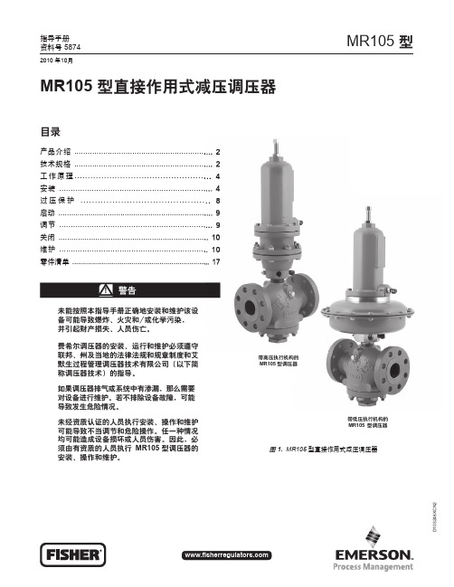
Fisher MR105自力式调压阀说明书
执行 机构类型
低压
高压
弹簧范围
psig 5 - 12 10 - 24 14 - 32 18 - 43 25 - 60(1) 43 - 100 75 - 175(2) 110 - 300(2)
bar 0,34 - 0,83 0,69 - 1,6 0,96 - 2,2
1,2 - 3,0 1,7 - 4,1(1) 3,0 - 6,9 5,2 - 12,1(2) 7,6 - 20,7(2)
弹簧 零部件号
弹簧 零部件号
弹簧线材直径
英寸
毫米
GE42909X012
白色
0.437
11,1
GE42910X012
银色
0.500
12,7
GE42911X012
橙色
0.562
14,3
GE43002X012
红色
0.625
15,9
GE42907X012
绿色
0.375
9,52
GE42909X012
白色
0.437
流量和选型系数 见表 5
大致重量 MR105 型低压执行机构 NPS 1 / DN 25 : 86 磅 / 39 公斤 NPS 2 / DN 50: 116 磅 / 53 公斤 NPS 3 / DN 80: 165 磅 / 75 公斤 NPS 4 / DN 100: 174 磅 / 79 公斤 MR105 型高压执行机构 NPS 1 / DN 25: 76 磅 / 34 公斤 NPS 2 / DN 50: 105 磅 / 48 公斤 NPS 3 / DN 80: 155 磅 / 70 公斤 NPS 4 / DN 100: 164 磅 / 74 公斤
11,1
GE42910X012
总结的Fisher型气动调节门调节要点

Fisher气动执行机构调整说明书Fisher气动执行机构Fisher气动调门上其配备的DVC6000系列数字式阀门控制器是可以通讯的、基于微处理器的电-气转换仪表,除了把电流信号转换成气动输出压力这一标准功能外,还可以通过275型HART通讯器很容易地访问对于过程操作至关重要地信息。
一、技术参数:输入信号:4~20mA直流,标准输出信号:为执行机构要求的气动信号,最大可达到气源压力的95%。
最少范围:(0.4bar6psig)最大范围:9.5bar(140psig)气源压力:推荐值:比执行机构要求的最大值高0..3bar(5psig)最大值:10.3bar(150psig)或执行机构最大压力额定值,取两者中较低者二、275型HART通讯器由于Fisher气动执行机构的控制器是用275型的HART通讯器来校验的,所以应该了解和掌握HA RT通讯器的使用。
275型HART通讯器主要由数字键盘,LCD显示器,操作键和功能键等部分组成,显示器可以显示8行x21字符,当与仪表连接时可以把仪表的信息传达出来。
数字键盘有两个功能:快速选择菜单选项和输入数据。
操作键主要是开关键、方向键、和热键。
HART通讯器通常在两种环境里使用:离线(不跟仪表连接时)和在线(跟仪表连接时)。
当打开HART通讯器时,它首先进行自HARTNoDeviceFound检,然后自动搜索兼容设备,如果没有找到设备,它就显示信息“”(没有找到设备)。
然后显示主菜。
屏幕上有四个选择:Offline(离线),Online(在线),FrequencyDevice(频率设备)以及Utility (属性)。
如果找到一个HART兼容设备,HART通讯器会显示Online(在线)菜单。
使用位于L CD下的标有F1F4至的四个功能键,可选择由动态字符说明的软件功能。
在任意给定的菜单里,出现在功能键上的字符说明该键在当前菜单里的功能。
可选功能包括:HELP(帮助)-提供给你关于显示选项的信息。
费希尔fisherDVC2000调试简易说明书
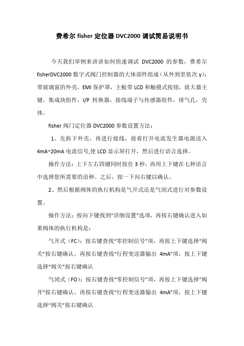
费希尔fisher定位器DVC2000调试简易说明书今天我们举例来讲讲如何快速调试DVC2000的参数,费希尔fisherDVC2000数字式阀门控制器的大体部件组成(从外到里依次y):带玻璃窗的外壳,EMI保护罩,主板带LCD和触摸式按钮,放大器主键,集成块组件,I/P转换器,接线端子与传感器组件,排气孔,壳体。
fisher阀门定位器DVC2000参数设置方法:1、先拆下外壳,再进行接线,接着打开电流发生器电源送入4mA~20mA电流信号,使LCD显示屏打开,然后进行语言选择。
操作方法:上下左右四键同时按住3秒,再用上下键在七种语言中选择您所需要的语种。
之后,按一下向右键以确认。
2、然后根据阀体的执行机构是气开式还是气闭式进行对参数设置。
操作方法:按向下键找到“详细设置”选项,再按右键确认进入如果阀体的执行机构是:气开式(FC):按右键查找“零控制信号”项,再按上下键选择“阀关”按右键确认。
再按右键查找“行程变送器输出4mA”项,按上下键选择“阀关”按右键确认气闭式(FO):按右键查找“零控制信号”项,再按上下键选择“阀开”按右键确认。
再按右键查找“行程变送器输出4mA”项,按上下键选择“阀关”按右键确认3、行程自动标定设置:操作方法:按向下键找到“行程标定”项,按右键确认进入,再按上下键选择“自动”按右键确认,LCD显示“按右键3秒钟阀门将动作”然后按照它的提示操作,它便可以自动搜索走完整个行程0%、100%、50%。
完成后按右键确认。
注:搜索途中不可退出,按任何键都不起作用,必须等走完整个行程才可以。
整定设置增益代码(C~M),C时阀门动作最慢,M时阀门动作最快。
选择合适的,一般设置为“L”,以阀门不振荡为准。
操作方法:按向下键找到“整定”项,按右键确认进入,再按上下键选择“自动”按右键确认,LCD显示“按右键3秒钟阀门将动作”然后按照它的提示操作,进入自动整定,接着等待,完成后按右键确认。
fisher-657-型-膜片式执行机构操作手册
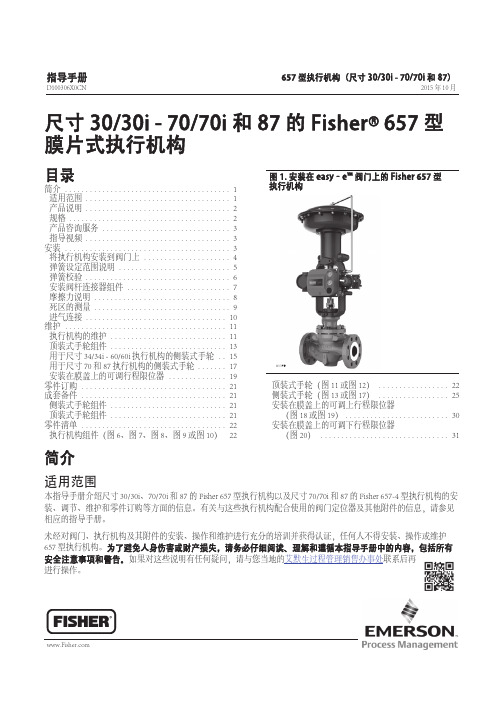
尺寸30/30i -70/70i 和87的Fisher X 657型膜片式执行机构目录简介1........................................适用范围1...................................产品说明2...................................规格2.......................................产品咨询服务3...............................指导视频3...................................安装3........................................将执行机构安装到阀门上4.....................弹簧设定范围说明5...........................弹簧校验6...................................安装阀杆连接器组件7.........................摩擦力说明8.................................死区的测量9.................................进气连接10..................................维护11.......................................执行机构的维护11............................顶装式手轮组件13............................用于尺寸34/34i -60/60i 执行机构的侧装式手轮15..用于尺寸70和87执行机构的侧装式手轮17.......安装在膜盖上的可调行程限位器19..............零件订购21...................................成套备件21...................................侧装式手轮组件21............................顶装式手轮组件21............................零件清单22...................................执行机构组件(图6、图7、图8、图9或图10)22图1.安装在easy‐e™阀门上的Fisher 657型执行机构X1175顶装式手轮(图11或图12)22.................侧装式手轮(图13或图17)25.................安装在膜盖上的可调上行程限位器(图18或图19)30.........................安装在膜盖上的可调下行程限位器(图20)31...............................简介适用范围本指导手册介绍尺寸30/30i、70/70i 和87的Fisher 657型执行机构以及尺寸70/70i 和87的Fisher 657-4型执行机构的安装、调节、维护和零件订购等方面的信息。
Fisher 1061 执行机构中文样本

1. 有效的执行机构扭矩基于特定结构和缸内压力。如需更多信息,请咨询艾默生过程管理费希尔销售办事处。 2. 不能超出本手册中温度 / 压力限制,或者适用的标准或规范的限定值。
2
产品样本
61.2:1061 2004 年 3 月
1061 执行机构
图 2. 1061 型执行机构剖面
表 1. 90 度旋转角情况下的容积改变
图 7 所示为 1061 型执行机构的外形尺寸。这些尺寸应该 同时要结合考虑图 3 所示的安装位置。
执行机构锁止装置 1061 型执行机构(尺寸 30 到 100)可以选用锁止装置, 这样可以保证执行机构在维修过程中保持在锁定位置上
尺寸 40 到 100 的 1061 型执行机构的可调行程上限位安 装在特定执行机构气缸的上部。其顶部攻有螺孔以便限 位的安装。组件包括螺钉,锁紧螺母和压力密封。可以 通过定位该螺钉以限制执行机构杠杆在 30 到 90 度旋角 范围内向上行程。可以使用更长螺钉以实现更大范围的 行程限位。
186
7.31
292 11.50
186
7.31
292 11.50
186
7.31
292 11.50
345 13.62 452 17.81
345 13.62 452 17.81
左手安装
图 3. 安装类型和位置(也可见表 3)
安装
执行机构一般情况下是垂直向上安在水平管道上。但是 对每一种类型而言,四个安装类型和四个安装位置都是 可能的(见图 3)
顺着管道内液体流动的方向看,如果执行机构在管道右 侧,则执行机构是右装,如果在管道左侧,是左装。
4
产品样本
61.2:1061 2004 年 3 月
费希尔调压阀说明书

费希尔调压阀说明书费希尔调压阀是一种技术先进、性能稳定的调节阀,通常用于液体、气体、蒸汽等介质的调节。
本说明书旨在介绍费希尔调压阀的结构、工作原理、安装使用、维护保养等方面的相关知识,以帮助用户正确使用并保障其安全运行。
一、结构简介费希尔调压阀由阀体、阀座、阀瓣、弹簧、阀盖等部件组成。
阀盖上设有调节螺帽和开放、关闭阀门的螺旋杆,通过杆与弹簧连接,使弹簧产生一定的压力。
阀瓣则通过旋转与阀座接触,用于调节介质的流量和压力。
阀座面采用不锈钢材料,能够耐受多种介质的腐蚀。
二、工作原理在正常工作状态下,压力入口通过管道进入阀体内部,由阀瓣调节介质流量、降压,经过阀座后流出调压阀输出口。
当介质压力高于设定值时,弹簧压缩,阀瓣适时关闭,介质流量减小,压力降低。
反之,当介质压力低于设定值时,弹簧伸长,阀瓣逐渐打开,介质流量增大,压力升高。
通过阀体上的调节螺帽,可以调节弹簧压力和阀门开度,实现对介质压力的精确控制和调节。
三、安装使用1.安装前应检查调压阀各部件是否完好,防止阀体内有杂物影响正常工作。
2.安装时应按照调压阀进出口标志和箭头方向正确安装。
3.应注意安装调压阀前后管道的清洁和对接完好,避免介质泄漏。
4.在安装前,应检查弹簧是否适合工作压力,如需要更换,请使用原厂生产的配套弹簧。
5.应注意不要损坏调节螺帽和阀门螺旋杆,避免调节不准确。
四、维护保养1.调压阀定期检查:每1-2个月对调压阀进行检查,观察是否有异常噪声、泄漏等情况,如有则及时处理。
2.清洗:清洗调压阀要用温水或清洁剂对外壳和内部部件进行清洗。
3.故障排除:如调节不准确或存在泄漏等问题,需及时调整或更换相应零件。
通过本说明书的介绍,用户可以了解到费希尔调压阀的结构、工作原理、安装使用和维护保养等方面的知识。
在实际使用中,用户应根据实际情况进行操作,确保调压阀的安全稳定运行。
Fisher气动阀说明书

Fisher气动阀1.工作原理电气转换器接收4~20mADC的电流指令信号,相应的输出3~15psi的气压作为气动定位器的输入信号。
定位器输入信号的变化,使它的喷嘴背压发生变化,定位器的放大器输出气压也相应变化,带动阀门动作。
同时,与阀门门杆相连的定位器反馈杆带动定位器的凸轮转动,从而改变了定位器喷嘴挡板的位置,使喷嘴背压发生改变,达到一个新的力平衡状态,阀门停在于指令信号相应的位置。
2.气压降落保位主要由保位阀实现。
将保位阀的动作压力调整在250~350psi的某个值上。
当保位阀控制气压高于调定值时,打开保位阀输出气路,使通往阀门气室的气路相通,即正常自动工作状态。
当气压低于调定值时,保位阀闭锁切换气路,切断通往阀门气室的气路,维持负载的原有位置,实现断气自锁保护。
3.结构Fisher气动阀的执行机构主要由气动定位器、电气转换器、位置变送器、断气保位装置及薄膜腔室构成。
4.基本误差及回程误差校准电气转换器检查校准(检查电气转换器的气源压力应为140psi左右。
)将信号电流分为4、8、12、16、20mA五个校准点,电气转换器的输出气压应与之对应为3、6、9、12、15psi,其误差应在±5%以内,回程误差小于2%,否则应进行调整。
调整时先将信号电流调至4mA,调零位螺母;再将电流调至20mA,调量程螺母使输出在额定值。
反复进行调整直至合格,应尽量使其准确。
5.执行机构检查校准检查气动定位器的气源压力应为35±2psi左右。
将校准后的电气转换器输出作为气动定位器的输入信号;全开全关的确认先应与本体专业进行联系确认全开及全关的位置,并将刻度盘固定,在调试定位器时应以刻度盘为基准。
6.不灵敏区校准:校准点应在25%、50%、75%、位置进行,方法为:将阀门操作在一定开度(如25%),稳定一会后,当阀位在30秒内不变化时,再缓慢加指令/或减指令,直到执行机构的位变产生变化为止,此时的指令变化的值就在阀门的不灵敏区。
Fisher DVC2000系列数字式阀门控制器-中文详细说明书

快速使用指南资料号57892005年1月DVC2000系列FIELDVUE® DVC2000系列数字式阀门控制器手册简介安装基本设置和校验技术规格和相关资料注意该手册提供了DVC2000系列数字式阀门控制器的安装、初始设置和校验、以及维护信息。
获得更多的信息,你可以阅读从Fisher销售商那里获得的FIELDVUE®DVC2000系列数字式阀门控制器使用手册——资料号 5772,或者直接访问我们的网址:DVC2000系列展开这一页以查看“现场液晶界面流程图”DVC2000系列现场液晶界面流程图主屏TRAVEL=66.8% 14.6 MA 0.92 BAR停止仪表动作行程偏差检查装配检查输入气源检查I/P(输入/输出)转换器在预设屏幕上以下项目是用警告图标进行确认的12 3 4 5 6 7 8快速设置阀门会移动3秒种定位0%...定位100%...定位0%...定位50%...行程校验校验阀门会移动3秒种自动手动调整调整阀门会移动3秒种阀门会移动3秒种自动手动详细设置零控制信号阀压力单位BAR自动手动关开BARPSIKPA阀门会移动3秒种模拟输入校验输入4 mAmA(输入会改变)3秒种阀位变送器校验送4 mA或送20 mA保存并退出?按保存并退出不保存退出控制现场控制手动SP=xxx控制=xxx模拟式或数字式手动式定位100%...定位0%...定位50%...定位50%...移动阀门至100%行程处自动手动移动阀门至0%行程处自动整定进行中...自动整定完成自动整定失败使用手动整定整定C衰减保存并退出不保存退出保存并退出?按+5不确定-5专家C,D,E,F,GHI,J,K,L,M输入范围下限 4 mA输入范围上限 20 mA特性曲线线形4 mA...19 mA5 mA...20 mA快开线形等百分比用户设置输入20 mA保存并退出?按保存并退出不保存退出只有在安装了变送器硬件的情况下才有用11111DVC2000系列更换主板SWITCH1=打开SWITCH2=关闭FW:1,HW1:1TUNING=C 保护 OFF关开只有在安装了限位开关的情况下才有用快速设置完成校准完成校准失败保存并退出?按保存并退出不保存退出英语法语西班牙语德语意大利语日语汉语语言 取消(返回主屏幕)注意:按住 + 3到10秒种+ + +语言选择 + + +3到10秒种变送器4 mA 限位开关1 90%限位开关1关闭 90%限位开关2 10%限位开关2关闭 10%关开125%...-25%高于低于无效125%...-25%低于高于无效保存并退出?按阀门可能移动 3秒种不保存退出?按只有在安装了变送器硬件的情况下才有用只有在安装了限位开关硬件的情况下才有用1111111DVC2000系列安装□ 正确地把用于阀门的仪表安装到执行机构上。
Fisher Type D2 FloPro控制阀说明书
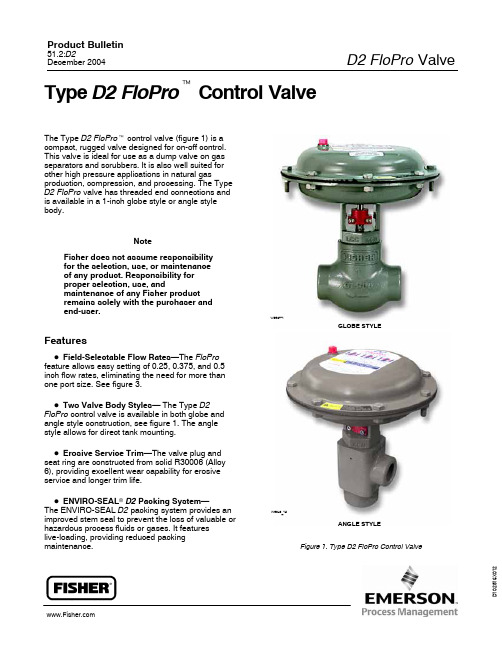
D 1 0 2 8 1 6 X 0 1 2Type D2 FloPro t Control ValveThe Type D2 FloPro t control valve (figure 1) is acompact, rugged valve designed for on-off control.This valve is ideal for use as a dump valve on gasseparators and scrubbers. It is also well suited forother high pressure applications in natural gasproduction, compression, and processing. The TypeD2 FloPro valve has threaded end connections andis available in a 1-inch globe style or angle stylebody.NoteFisher does not assume responsibilityfor the selection, use, or maintenanceof any product. Responsibility forproper selection, use, andmaintenance of any Fisher productremains solely with the purchaser andend-user.FeaturesD Field-Selectable Flow Rates—The FloPro feature allows easy setting of 0.25, 0.375, and 0.5 inch flow rates, eliminating the need for more than one port size. See figure 3.D Two Valve Body Styles— The Type D2 FloPro control valve is available in both globe and angle style construction, see figure 1. The angle style allows for direct tank mounting.D Erosive Service Trim—The valve plug and seat ring are constructed from solid R30006 (Alloy 6), providing excellent wear capability for erosive service and longer trim life.D ENVIRO-SEAL r D2 Packing System—The ENVIRO-SEAL D2 packing system provides an improved stem seal to prevent the loss of valuable or hazardous process fluids or gases. It featureslive-loading, providing reduced packing maintenance.W8527-1W9040_1aGLOBE STYLEANGLE STYLEFigure 1. Type D2 FloPro Control Valve2GLOBE STYLE AIR-TO-OPEN ANGLE STYLE AIR-TO-OPEN W9005-1W9006-1Figure 2. Type D2 FloPro ConstructionsD NACE MR0175 Service-Ready—NACE trim isthe standard construction for the D2 FloPro control valve. The valve body, bonnet, and trim materials comply with the recommendations of NACEMR0175.D ASME Class 900—Valve assembly is designed and specified for ASME B16.34 Class 900 service.D Low Temperature Materials—Valve and actuator construction materials allow use in low temperature applications of –46° C.D Field-Reversible Actuator—The Type D2 FloPro actuator can be converted in the field from Air-to-Open to Air-to-Close actuator action. (Conversion to Air-to-Close actuator action requires removing four springs from the actuator casing configuration.) (Conversion to Air-to-Open actuator action requires adding four springs to the actuator casing configuration.)D Easy Installation—Compact design allows installation where space is at a premium.D Easy Maintenance—Screwed bonnet/body joint allows repair or maintenance with a minimum of tools and without removing the valve body from the piping system.30.5 INCH FLOW RATE(Cv = 6)0.375 INCH FLOW RATE(Cv = 4)0.25 INCH FLOW RATE(Cv = 2)123123FloPro INDICATOR W8330-1Figure 3. Travel and Flow Coefficients19B8490-B E0783mm (INCH)Figure 4. Type D2 Globe Valve Dimensions (Air-to-Open Configuration Shown)GE13418-AE0972Figure 5. Type D2 Angle Valve Dimensions (Air-to-Open Configuration Shown) 41. The pressure or temperature limits in the referenced tables and any applicable ASME code limitations should not be exceeded.2. Standard flow direction.5proper selection, use, andmaintenance of any Fisher product remains solely with the purchaser andend-user.FisherMarshalltown, Iowa 50158 USA Cernay 68700 France Sao Paulo 05424 Brazil Singapore 128461The contents of this publication are presented for informational purposes only, and while every effort has been made to ensure their accuracy, they are not to be construed as warranties or guarantees, express or implied, regarding the products or services described herein or their use or applicability.We reserve the right to modify or improve the designs or specifications of such products at any time without notice.Fisher does not assume responsibility for the selection, use or maintenance of any product. Responsibility for proper selection, use and maintenance of any Fisher product remains solely with the purchaser and end-user.ENVIRO-SEAL, FloPro, and Fisher are marks owned by Fisher Controls International LLC, a member of the Emerson Process Management business division of Emerson Electric Co. The Emerson logo is a trademark and service mark of Emerson Electric Co. All other marks are the property of their respective owners. This product may be covered by one or more of the following patents: 5,129,625; 5,131,666; 5,056,757;5,230,498; 5,299,812; 6,698,449 B2; 6,695,000 B2; and 6,769,666 or under pending patents.Emerson Process Management 。
Fisher GX 三通阀和执行机构维护手册说明书

Fisher ® GX三通阀和执行机构目录介绍.......................................................................1手册范围................................................................1说明.......................................................................1规格.......................................................................2阀门安装.....................................................................2维护.............................................................................3执行机构维护.........................................................5填料维护................................................................7更换填料................................................................8阀内件维护..........................................................10成套零件...................................................................13零件清单. (14)介绍手册范围该指导手册包括Fisher ® GX 三通阀和执行机构的安装、维护及零件信息。
Fisher V500旋转球阀技术手册说明书
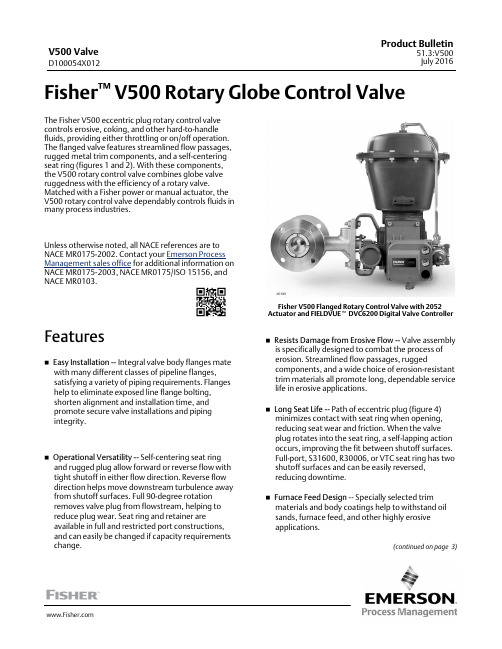
Fisher™ V500 Rotary Globe Control Valve The Fisher V500 eccentric plug rotary control valvecontrols erosive, coking, and other hard-to-handlefluids, providing either throttling or on/off operation.The flanged valve features streamlined flow passages,rugged metal trim components, and a self-centeringseat ring (figures 1 and 2). With these components,the V500 rotary control valve combines globe valveruggedness with the efficiency of a rotary valve.Matched with a Fisher power or manual actuator, theV500 rotary control valve dependably controls fluids inmany process industries.Unless otherwise noted, all NACE references are toNACE MR0175-2002. Contact your Emerson ProcessManagement sales office for additional information onNACE MR0175-2003, NACE MR0175/ISO 15156, andNACE MR0103.Featuresn Easy Installation -- Integral valve body flanges mate with many different classes of pipeline flanges,satisfying a variety of piping requirements. Flanges help to eliminate exposed line flange bolting,shorten alignment and installation time, andpromote secure valve installations and pipingintegrity.n Operational Versatility -- Self-centering seat ring and rugged plug allow forward or reverse flow with tight shutoff in either flow direction. Reverse flow direction helps move downstream turbulence away from shutoff surfaces. Full 90-degree rotationremoves valve plug from flowstream, helping toreduce plug wear. Seat ring and retainer areavailable in full and restricted port constructions, and can easily be changed if capacity requirements change.X0189Fisher V500 Flanged Rotary Control Valve with 2052 Actuator and FIELDVUE t DVC6200 Digital Valve Controller n Resists Damage from Erosive Flow -- Valve assembly is specifically designed to combat the process oferosion. Streamlined flow passages, ruggedcomponents, and a wide choice of erosion-resistant trim materials all promote long, dependable service life in erosive applications.n Long Seat Life -- Path of eccentric plug (figure 4) minimizes contact with seat ring when opening,reducing seat wear and friction. When the valveplug rotates into the seat ring, a self-lapping action occurs, improving the fit between shutoff surfaces.Full-port, S31600, R30006, or VTC seat ring has two shutoff surfaces and can be easily reversed,reducing downtime.n Furnace Feed Design -- Specially selected trim materials and body coatings help to withstand oil sands, furnace feed, and other highly erosiveapplications.(continued on page 3)(continued) 231. The reversible seat is not available in every trim material. Consult your Emerson Process Management sales office .2. The pressure or temperature limits in the referenced tables or figures, and in any applicable code limitation, should not be exceeded.3. Ratio of maximum flow coefficient to minimum usable flow coefficient. May also be called rangeability.Features (continued)n Simple Assembly and Maintenance -- No specialorientation, precision clamping or repetitive centering of valve plug and seat ring is required when tightening the retainer, promoting accurate alignment and easy assembly.n Improved Environmental Capabilities -- The optionalENVIRO -SEAL packing systems are designed with very smooth shaft surfaces and live loading to provide improved sealing. The seal of theENVIRO -SEAL system can restrict emissions to less than the EPA (Environmental Protection Agency)limit of 100 ppm (parts per million).n Sour Service Capability -- Trim and bolting materialsare available for applications handling sour service.These materials comply with the requirements of NACE MR0175-2002. Contact your Emerson Process Management sales office for additional information.n Rugged Construction -- Durable, solid metal or VTCseat ring and valve plug shutoff tightly without deforming plug arms or employing thin ball seals.Oversized shaft diameters and rugged trim parts allow high pressure drops. Tungsten carbide is also available for erosive service.n Reliable Performance -- Seat ring design (figure 2)self -centers, self -laps, and dynamically aligns with plug, giving excellent cycle life. Sealed metalbearings (see figure 1) help prevent particle buildup and valve shaft seizure in erosive applications.n Choice of Construction Materials -- Plug, seat ring,and retainer are available in four levels of hardness for selection of erosion resistance.n Optional Alloy 6 Seat Ledge Insert Available --Protects seat and valve body from high-velocity erosive flows and eases repair. Available for NPS 2-8.ContentsFeatures 1.....................................Specifications 2................................Installation 14.................................TablesValve Size, Pressure Ratings, and FlangeCompatibility 6..............................Material Combinations 6........................Material Temperature Capabilities 7...............Maximum AllowableShutoff Pressure Drops 8......................Actuator Mounting Selections 14.................Dimensions 15.................................41End-tapped valve body and pipe plug optional (limited to less than 232_C [450_F])O-RINGSBEARING STOPVALVE BODYTAPER ANDEXPANSION PINSDETAIL OF SEALED BEARINGS1W4172-2W4170-31W9275FURNACE FEED (FFD) TRIMRETAINER RESISTS EFFECTS OF EROSIONAPPLIED TO INTERNAL FLOW PASSAGEBODY INSERT PROTECTS THE SEAT AND BODY FROM HIGH VELOCITY EROSIVE FLOWS AND EASES REPAIR549A3685-C A3288-2REVERSE FLOW SHUTOFF(STANDARD)FORWARD FLOW SHUTOFFFACE SEALSECTIONFLOWDIRECTIONFLOWFigure 3. Typical ENVIRO-SEAL Packing Arrangements for Rotary ValvesPACKINGYOKE YOKE VALVE BODYANTI-EXTRUSION RINGSPTFE PACKING V-RINGS SHOWNVALVE PACKING BOX RINGGRAPHITE PACKING SETPACKING FOLLOWERSPRINGS SINGLE PTFE PACKING GRAPHITE PACKINGW6125-1W5806-16Table 2. Valve Size, EN Pressure Ratings, and Flange Capability (X indicates availability)VALVE SIZE, DNFlangedPN 10PN 16PN 25PN 40PN 63PN 10025405080100150200X X X X X X XX X X X X X XX X X X X X XX X X X X X XX X X X X X XX X X X X X XTable 3. Material CombinationsTrim LevelBody MaterialValve Size, NPS Valve Plug Seat Ring Retainer 1WCC1 & 1-1/2CF8M/Chrome Plate CF8M CF8M2 through 8CF8M/Chrome Plate CF8M CB7Cu-1CF8M 1 through 8CF8M/Chrome Plate CF8M CF8M CF3M (2) 1 through 8CF3M/Chrome PlateCF3M CF3M 2WCC1 & 1-1/2R30006R30006CF8M2 through 8R30006R30006CB7Cu-1CF8M 1 through 8R30006R30006CF8M CF3M (2)1 through 8R30006R30006CF3M3WCC/CF8M/CF3M (1,3)1 & 1-1/2R30006R30006CF8M/R30006 bore or CF3M/R30006 bore (3)2 through 8R30006R30006R300063H (over 600°F)CF8M/CF3M (3)2 through 8R30006R30006CF8M/R30006 bore or CF3M/R30006 bore (3)4(5,6)WCC/CF8M/CF3M (3)1 & 1-1/2(4)Solid VTC Solid VTC CF8M/VTC bore or CF3M/VTC bore (3)2(4)Solid VTCSolid VTC R30006/VTC bore 3 through 8R30006 hub, Titanium Gr 5cap screw, and VTC surfacecap Solid VTCR30006/VTC bore4S (5,6)WCC/CF8M/CF3M (3) 3 through 8R30006 hub, S17400SST treated insert, N07718 cap screw, and VTC surface cap Solid VTC R30006/VTC boreFFD (6)CF8M with Tungsten Carbide Coating and R30006 Drop-in SeatLedge2 through 8R30006/Tungsten CarbideSeating SurfaceSolid VTC CF8M/R30006 Bore1. Trim 3 for NPS 2 through 8 stainless steel bodies is limited to 600_F.2. European Sourcing Only.3. European sources supply CF3M in lieu of CF8M.4. Includes an S20910 SST shaft for NPS 1, 1-1/2, and 2.5. Use trim 4S when sour service construction is required for compliance to NACE MR0175-2002.6. VTC trim is not compatible with water and steam above 180_C (360_F).7891011121314InstallationThe V500 control valve may be installed in any position. However, for best shutoff performance, a position with the shaft horizontal is recommended.The control valve may be installed in forward orreverse flow direction. Forward flow (through the seat ring and past the plug) tends to open the valve; reverse flow (past the plug and through the seat ring) tends to close the valve. The reverse flow direction is recommended for erosive applications.Specific operating conditions may require a specific combination of push -down -to -close or -open actuator motion and open valve plug position above or below the shaft. To satisfy specific operating requirements,the complete control valve package (valve andactuator) can be assembled and installed in different ways, providing eight options for actuator motion and open plug position.Table 11 and the appropriate actuator bulletindescribe possible assembly and installation options.For assistance in selecting the appropriate combination of actuator action and open valveposition, consult your Emerson Process Management sales office .Dimensions are shown in figure 5.Valve InformationTo determine the required valve ordering information,refer to the Specifications table. Review theFigure 4. Eccentric RotationB1879-1VALVE BODY CENTERLINE VALVE SHAFT CENTERLINEVALVE BODY CENTERLINE VALVE SHAFT CENTERLINEVALVE BODY CENTERLINE VALVE SHAFT CENTERLINE15Figure 5. Fisher V500 Rotary Control Flanged Valve Dimensions (refer to table 12)Note:For dimensions of valves with DN (or other) end connections, consult your Emerson Process Management sales office .A3289-1CL150, CL300,OR CL600 WITH RF OR RTJ FLANGESNPS 1, 1-1/2 AND 2BODY MOUNTING NPS 3 AND 4BODY MOUNTING NPS 6 AND 8BODY MOUNTINGEmerson Process ManagementMarshalltown, Iowa 50158 USA Sorocaba, 18087 Brazil Cernay, 68700 FranceDubai, United Arab Emirates Singapore 128461 SingaporeThe contents of this publication are presented for informational purposes only, and while every effort has been made to ensure their accuracy, they are not to be construed as warranties or guarantees, express or implied, regarding the products or services described herein or their use or applicability. All sales are governed by our terms and conditions, which are available upon request. We reserve the right to modify or improve the designs or specifications of such products at any time without notice.Fisher, FIELDVUE, and ENVIRO-SEAL are marks owned by one of the companies in the Emerson Process Management business unit of Emerson Electric Co.Emerson Process Management, Emerson, and the Emerson logo are trademarks and service marks of Emerson Electric Co. All other marks are the property of their respective owners.Neither Emerson, Emerson Process Management, nor any of their affiliated entities assumes responsibility for the selection, use or maintenance of any product. Responsibility for proper selection, use, and maintenance of any product remains solely with the purchaser and end user.。
fisher中文说明书
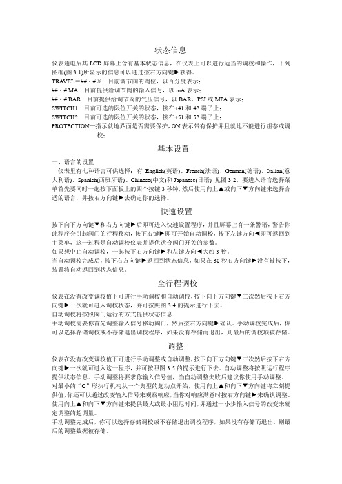
状态信息仪表通电后其LCD屏幕上含有基本状态信息,在仪表上可以进行适当的调校和操作,下列图框(图3-1)所显示的信息可以通过按右方向键►获得。
TRA VEL=##·#%—目前调节阀的阀位,以百分度表示;##·# MA—目前提供给调节阀的输入信号,以mA表示;##·# BAR—目前提供给调节阀的气压信号,以BAR、PSI或MPA表示;SWITCH1—目前可选的限位开关的状态,接在+41和-42端子上;SWITCH2—目前可选的限位开关的状态,接在+51和-52端子上;PROTECTION—指示就地界面是否需要保护,ON表示带有保护并且就地不能进行组态或调校;基本设置一、语言的设置仪表里有七种语言可供选择:有English(英语)、French(法语)、German(德语)、Italian(意大利语)、Spanish(西班牙语)、Chinese(中文)和Japanese(日语) 见图3-2,要进入语言选择菜单首先要同时一起按下面板上的四个按键3秒钟,然后使用向上▲或向下▼方向键来选择合适的语言,并按右方向键►去确定你的选择。
快速设置按下向下方向键▼和右方向键►后即可进入快速设置程序,并且屏幕上有一条警语,警告你此程序会引起阀门的行程移动,按下右键►即可开始自动调校,按下左键方向◄即可返回到主菜单,这一过程是自动调校仪表并提供适合阀门开关的参数。
如果想中止自动调校,一起按下右方向键►和左键方向◄大约3秒。
当自动调校完成后,按下右方向键►返回到状态信息,如果在30秒右方向键►没有被按下,装置将自动返回到状态信息。
全行程调校仪表在没有改变调校值下可进行手动调校和自动调校,按下向下方向键▼二次然后按下右方向键►一次就可进入调校状态,并可按照图3-4的提示进行下去。
自动调校将按照阀门运行的方式提供状态信息手动调校需要你首先调整输入信号移动阀门,然后按右方向键►确认。
手动调校完成后,你可以选择存储调校或不存储退出调校程序,如果没有存储而退出,则最后的调校项被存储。
Fisher N563和N863紧急关闭阀门说明书
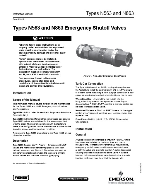
Types N563 and N863D 450338T 012Instruction ManualAugust 2015Types N563 and N863 Emergency Shutoff ValvesFailure to follow these instructions or to properly install and maintain this equipment could result in an explosion and/or firecausing property damage and personal injury or death.Fisher ® equipment must be installed, operated and maintained in accordance with federal, state and local codes and Emerson Process Management Regulator Technologies, Inc. instructions. Theinstallation must also comply with NFPA No. 58, ANSI K61.1, and DOT standards.Only personnel trained in the proper procedures, codes, standards andregulations of the applicable industries shall install and service this equipment.IntroductionScope of the ManualThis instruction manual covers installation and maintenance for the Types N563 and N863 Emergency Shutoff Valves and Accessories.Type N563 is UL ®Listed for service in Propane or Anhydrous Ammonia (NH 3).Type N863 is intended for all other compressed gas service. Type N863 valves are serialized for the service specified with the order. The user should check with the factory tomake sure the Type N863 valve materials are suitable for the intended service and temperature conditions.Reference to Type N563 also refers to the Type N863 unless otherwise specified.DescriptionType N563 Snappy Joe™, Figure 1, Emergency Shutoff Valves are intended for transferring product to or from railroad tank cars, see Figure 2. The valves are used as temporary connections between the tank car’s primary shutoff valves and the hose or swivel type piping.Figure 1. Type N563 Emergency Shutoff ValveTank Car ConnectionThe Type N563 has a 2 in. FNPT coupling allowing the user the flexibility to install the desired length of 2 in. NPT piping to fit the tank dome. Replacing a worn out pipe connection is now easier as any desired length of schedule 80 pipe can be used.Wrenching Hex – A wrenching hex is built into the body, minimizing wear or damage when connecting ordisconnecting. A 1/4 in. FNPT opening in the hex portion can be used to install a bleed valve.Hardened Threads – The 2 in. FNPT threads on the nipple portion are of hardened stainless steel to reduce wear from repeated use.Fuse Plug – Melting point 212°F / 100°C. Closes valve when melted.InstallationGeneralA typical installation schematic is shown in Figure 3, where two valves are installed on the liquid lines and one on the vapor line. T o meet NFPA Pamphlet 58 requirements, emergency shutoff valves must have a means of closure at both the valve and a remote location. A quick-disconnect coupling provides manual control at the valve. A suitable two-way or three-way closure valve is required at a remote location, preferably near the exit of the transfer site .UL ®is a mark owned by Underwriters Laboratories.Types N563 and N8632Remote ClosureA bleed orifice is required on the outlet of the pressure source regulator and before the remote closure valve. This restricts the pressure source flow to the system. Failure to install a bleed orifice may not allow the control pressure to exhaust quickly enough to close the emergency valves if the remote valve is used or the control pressure line is broken.The Remote Closure Valve should be simple in operation and have enough capacity to quickly exhaust pressure between the supply source and the Type N563. A bleedorifice, Fisher ® part number 1D7470, should be placed in-line after the pressure supply regulator to restrict flow. This allows the remote closure valve to exhaust pressure, and thus close the Type N563.Pressure Supply LineThe manual quick disconnect valve must be used as the primary source to open and close the Type N563. Do not bypass the manual quick disconnect valve by hardpiping the supply line to the Type N563. Failure to use the manual quick disconnect will negate a portion of the NFPA 58requirements for Emergency Shutoff Valves.Regardless of how many remote closure valves are installed in the system, the quick-disconnect coupling at the valve is the primary means to open and close the Type N563. Do not hard pipe the supply line to the Type N563 and then use a remote closure valve as the primary activation valve.The pressure supply line to the Type N563 can be run along the transfer line back to a common pressure source and remote closure valve. In this way actuating the remote closure valve can close all emergency shutoff valves. It is recommended that a remote closure valve be installed on the working level of the unloading riser for the convenience of personnel, however, it should not be used as the primary means to open and close the Type N563.Pressure SourceThe pressure source should be clean, dry gas such as air, nitrogen or CO 2 . A Fisher Type 1301F regulator or equivalent can be used to reduce the high pressures encountered with these compressed gases.Approximately 50 psig / 3.4 bar is needed to open the N563 Series. (Less control pressure is required with low product pressures.)SpecificationsThe Specifications section lists the specifications for Types N563 and N863 Emergency Shutoff Valves. Factory specification is stamped on the nameplate fastened on the valve at the factory.TYPE ELASTOMER UL ® LISTEDINLET CONNECTION, IN.OUTLET CONNECTION, IN.N563-16Nitrile (NBR)Yes2 FNPT2 FNPT N563-263-1/4 Male AcmeN863E-16EPDM No 2 FNPT N863E-263-1/4 Male AcmeN863K-16Kalrez ®(1)2 FNPT N863K-263-1/4 Male AcmeN863N-16Neoprene (CR) 2 FNPT N863N-263-1/4 Male AcmeN863T-16Teflon ®(2) 2 FNPT N863T-263-1/4 Male AcmeN863V-16Viton ®(3)2 FNPT N863V-263-1/4 Male Acme1. Perfluoroelastomer (FFKM) equivalent.2. PTFE equivalent.3. Fluorocarbon (FKM) equivalent.4. The pressure limits in this Instruction Manual or any applicable standard limitation should not be exceeded.Maximum Relief Inlet Pressure (4): 400 psi / 27.6 bar Fuse Link Melting Temperature: 212°F / 100°CKalrez ®, Teflon ® and Viton ® are marks owned by E.I. Du Pont de Nemours and Co.UL ® is a mark owned by Underwriters Laboratories.Approximate Weightswith FNPT Outlet: 12.6 lbs / 5.7 kg with Acme Outlet: 15.3 lbs / 6.9 kgTypes N563 and N8633Roll-Away ProtectionIt is not possible to insure that Type N563 valves will remain installed or intact in the event of a tank car rollaway. Therefore,additional protection for the riser piping and valves are required.Due to the various configurations of railcar domes, valves and unloading risers, the Type N563 valve(s) may not remain installed or intact during a rollaway.It is recommended that a break-off pipe protect both the riser hoses and the Type N563 valves. This break-off pipe should be installed downstream of the protected tower back check valves and ESV so that the break-off pipe threads pull out before the hoses are pulled with more than 1500 lbs / 680 kg of force. A schedule 80 pipe takes around 3000 ft-lbs / 4067 N•m of torque to pull out at the threads.Pneumatic AccessoriesUse commercially available pneumatic controls, fittings and tubing for the pressure control lines. Pneumatic 3-way valves should quickly exhaust supply pressure to the Type N563 valves and at the same time shutoff inlet pressure.Operation1. Make sure the 2 in. NPT threads on the Type N563 and the Schedule 80 pipe nipple are clean and in good condition. Use an appropriate pipe compound on the male threads. Thread the nipple hand tight into the 2 in. FNPT inlet end of the Type N563. Then wrench tighten the nipple approximately two (2) additional turns. Check the connection for leaks.2. Tighten the 3 set screws (1/4-20 UNC x 0.25 in.) against the pipe nipple. This helps secure the nipple to the Type N563 so that the nipple does not unscrew at the Type N563 instead of the tank car valve.3. Slowly, but completely open the tank car’s primary shutoff valves. Begin product transfer.4. If the valve does close, stop the transfer and close the nearest downstream valve and the tank car’s primary shut off valve. Wait for the Type N563 valve to click open.5. All valves should be completely open when pumping.6. The operator must always be aware of where the remote closure controls are located and know how to operate the controls if an emergency requires valve closure.7. When the transfer has been completed, close the primary shutoff valves.8. Bleed down the transfer hose or piping to avoid trapping pressure between the primary shutoff valve and the Type N563.9. Close the Type N563 by taking off the quick-disconnect coupling. (T o remove the coupling simply pull back on the release sleeve.)10. Unscrew the transfer hose or piping from the Type N563,and take the Type N563 off the primary shutoff valve.MaintenanceOnly qualified service personnel shouldattempt to repair these valves. Before starting any type of repair, close off the upstreamvalves and remove all pressure from both the inlet and outlet of the Type N563 Emergency Shutoff Valve.At least once a month inspect and check the following things:1. See that the remote closure valve(s) works freely. Operate the valve to make certain it closes the Type N563.2. Make sure the quick-disconnect nipple is not blocked or its exterior damaged or worn.3. Check the quick-disconnect coupling for retention of supply pressure when disconnected and check for leaks when coupled.4. Check for worn or damaged threads.5. Check for joint leakage.6. Retighten the 3 set screw securing the inlet piping to the Type N563.Figure 2. Typical Railcar Hook-upTANK CARTypes N563 and N863Replacing Inlet Nipple1. Loosen the 3 set screws securing the inlet piping to the Type N563.2. Remove the inlet nipple.3. Make sure the 2 in. NPT threads on the Type N563 and the Schedule 80 pipe nipple are clean and in good condition. Use an appropriate pipe compound on the male threads. Thread the nipple hand tight into the 2 in. FNPT inlet end of the Type N563. Then wrench tighten the nipple approximately two (2) additional turns. Check the connection for leaks.4. Tighten the 3 set screws (1/4 -20 UNC x 0.25 in.) against the pipe nipple. This helps secure the nipple to the Type N563 so that the nipple does not unscrew at the Type N563 instead of the tank car valve.Replacing Internal PartsWith the exception of the quick-disconnect coupling and nipple and the Acme coupling, the Type N563 is not designed for field repair. Due to the use of special fire-resistant seals and assembly techniques, repair should be made only by trained personnel. If repair becomes necessary, contact your Fisher ® distributor or the factory for information and assistance.Only parts manufactured by Fisher should be used for the repair of Fisher Type N563 Valves. Be sure to give the complete type number of the Type N563 when corresponding with the factory.Type N563 Valves that have been disassembled for repair must be tested for proper operation before being returned to service.Repair KitN562-REPAIR (Types N562 and N563 Railcar repair service)(1)1. Contact your Fisher Distributor.The Emerson logo is a trademark and service mark of Emerson Electric Co. All other marks are the property of their prospective owners. Fisher is a mark owned by Fisher Controls International LLC, a business of Emerson Process Management.The contents of this publication are presented for informational purposes only, and while every effort has been made to ensure their accuracy, they are not to be construed as warranties or guarantees, express or implied, regarding the products or services described herein or their use or applicability. We reserve the right to modify or improve the designs or specifications of such products at any time without notice.Emerson Process Management Regulator Technologies, Inc. does not assume responsibility for the selection, use or maintenance of any product. Responsibility for proper selection, use and maintenance of any Emerson Process Management Regulator Technologies, Inc. product remains solely with the purchaser.©Emerson Process Management Regulator Technologies, Inc., 2013, 2015; All Rights ReservedLPG EquipmentEmerson Process Management Regulator Technologies, A - HeadquartersMcKinney, Texas 75070 USA Tel: +1 800 558 5853Outside U.S. +1 972 548 3574For further information visit Figure 3. Installation Schematic of N563 SeriesPRESSURE SOURCESHUTOFFFISHER TYPE 1301VAPORSUGGESTED ADDITIONAL CLOSURE VALVE AT PRESSURE SOURCE (CAN BE PRIMARY REMOTE CLOSURE VALVE IF PRESSURE SOURCE SYSTEM IS LOCATED AT A SAFE REMOTE LOCATION)TRANSFER HOSE UNLOADING TOWERSUPPLY PRESSURETUBINGID7470RESTRICTIONORIFICELIQUIDPRIMARY REMOTE CLOSER VALVE NEAR AREA EXITTYPE N563 EMERGENCY VALVE TANK CAR SHUT OFF VALVESSUGGESTED ADDITIONAL CLOSURE VALVE。
智能调节阀(FISHER)

智能气动薄膜调节阀〔FISHER〕1、所需仪器设备2、校验方法2.1调校前的膜头气密试验将与最大气信号压力等值的仪表净化风输入薄膜气室,切断气源后5min内,气室压力不应下降。
2.2阀体耐压强度试验此工作要求委托具备阀体耐压强度试验资质的试验站做强度试验,由校验人员做阀门开关的配合工作。
试验在阀门全开状态下用〔5~10℃〕的干净水进展,要求耐压强度试验压力为公称压力的1.5倍时,所有在工作中承受压力的压腔承压3min,没有可见的泄漏现象。
常用ANSI〔psi〕标准与常用PN〔MPa〕标准的换算:2.3阀门的泄漏量试验要求试验所用介质为5~10℃〔空气或氮气〕或清洁水,试验压力为0.35Mpa。
当阀的允许压差小于0.35Mpa时,应选用设计规定的值。
试验时气开阀的气动信号压力为零,气关阀的信号压力为输入信号上限值加上20Kpa;用量杯量取泄漏的介质量,然后与计算的允许泄漏量进展比拟来判断其泄漏是否合格。
当用气体介质做试验时,用排水取气法收集泄漏的气体量进展比拟。
允许泄漏量计算(依据如下附表1-3)附表1调节阀泄漏量分级注:⑴△P为阀前后压差〔kPa〕;⑵D为阀座直径〔mm〕;⑶对于可压缩流体体积流量,绝对压力为101.325kPa和绝对温度为273K的标准状态下的测量值;⑷A试验程序时,应为0.35MPa,当阀的允许压差小于0.35MPa时,用设计规定的允许压差;⑸B试验程序时,应为阀的最大工作压差。
附表2调节阀的额定容量计算公式注:Q1—液体流量〔m3/h〕;Qg—标准状态下的气体流量〔m3/h〕; K V—额定流量系数;t—试验介质温度〔℃〕取20℃; P1—阀前绝对压力〔kPa〕; P2—阀后绝对压力〔kPa〕;△P—阀前后压差〔kPa〕;; G—气体比重,空气比重为1;ρ/ρ0—相对密度〔规定温度范围内的水ρ/ρ0为1〕。
计算方法:以试验介质为规定温度范围的水,试验压力ΔP=0.35Mpa〔350Kpa〕为例依据公式 011.0ρρPk Q V∆=计算出Q 1〔阀额定容量〕 计量单位为 m 3/h〔此情况下 ρ/ρ0为1 Kv=Cv/1.169 Cv 为调节阀选用的流通能力为〕 再依据附表1〔或说明书中规定的允许泄漏量〕计算出允许的最大阀座泄漏量〔L/h 〕 将之单位换算为ml/min 既可。
费希尔调压阀说明书

费希尔调压阀说明书篇一:标题: 费希尔调压阀说明书正文:费希尔调压阀是一种广泛应用于各种工业设备和管道上的安全、可靠的调节阀。
它主要用于调节管道中的压力,以达到预定的目标。
本说明书将详细介绍费希尔调压阀的工作原理、使用方法和注意事项。
一、工作原理费希尔调压阀由两个阀门和一个控制器组成。
其中一个阀门是主阀门,另一个是调节阀门。
主阀门和调节阀门之间的连接管道称为调压管。
当需要调节管道中的压力时,可以通过控制调节阀门的开度来调节主阀门的输出流量,从而实现压力的调节。
二、使用方法1. 安装调压阀将调压阀安装在管道上,并确保与管道的连接正确。
安装时需要注意调压阀的密封圈是否磨损,如果有磨损需要更换密封圈。
2. 连接调压管将调压管连接到调压阀的进气管和输出水管上。
连接时需要注意调压管的接口是否正确,管径是否匹配,并确保连接处密封良好。
3. 打开主阀门打开主阀门,使调压管中的水流动起来。
此时,调压阀的控制器将开始工作。
4. 调节调节阀门通过调节调节阀门的开度,可以控制调压管中的压力。
调节时需要注意调节阀门的开度不要过大,以免对管道造成损坏。
5. 关闭主阀门当调节调节阀门的开度达到所需值时,关闭调节阀门。
此时,调压阀的控制器将停止工作。
6. 测试调压效果在使用完调压阀后,需要对调压效果进行测试。
将调压阀关闭,测量调压管中的压力,确保达到预定的目标。
三、注意事项1. 调压阀应安装在管道的适当位置,避免安装在压力过高或过低的区域。
2. 在使用调压阀时,应确保调压管的接口正确,管径匹配,密封良好。
3. 调压阀的控制器应定期检查,确保其正常工作。
4. 在使用调压阀前,应仔细阅读说明书,了解其使用方法和注意事项。
5. 禁止在危险的环境中使用调压阀。
四、总结费希尔调压阀是一种广泛应用于各种工业设备和管道上的安全、可靠的调节阀。
它简单易用,性能稳定,可以有效地调节管道中的压力。
在使用费希尔调压阀时,需要安装正确,注意使用方法和注意事项,并定期检查和维护。
FISHER299H减压阀说明
FISHER299H减压阀说明美国艾默生集团旗下的FISHER公司燃气输配技术掌握了世界领先的调压技术,其高质量标准已得到世界燃气行业的认可。
广州赫蒂能源设备有限公司是美国FISHER产品总代理商,拥有稳固的客户群,及专业的售后服务队伍。
我们已获得ISO9001质量管理系统认证,在可靠性、效率、安全操作及性价比方面为用户创造了巨大效益。
美国FISHER公司拥有一百多年生产优秀产品的历史,为天然气工业提供解决方案已历经三十余年;费希尔燃气输配技术是该领域公认的领先公司,其业务遍及全球。
FISHER299H减压阀描述●调压精确、关闭灵敏、压力设定简单●大皮膜执行机构组合指挥器使得调压器动作灵敏,反应速度快●一体化的过压、失压切断装置,确保用户安全●可在线维修●可作监控连接,保证安全●流通能力大,结构紧凑;密封严密,无气体渗漏●安装省力,经济实惠●选项:可在指挥器前配置过滤器●内置超高压/超低压切断装置●大皮膜执行机构组合指挥器使得调压器动作灵敏,反应速度快●多种压力信号选取方式FISHER299H减压阀参数●进口压力范围:最大12.1bar●出口压力范围:9m bar-4.14bar(详情咨询代理-壹捌零贰柒叁柒陆壹捌肆)●最大流量:2.898Nm3/h●精度:±2.5%●连接方式:2"螺纹,ANSI125FF/150RF/250RF/300RF/PN10/PN16法兰●材料:铸铁,韧性铸铁或WCB钢制阀体●温度:-29°~66℃●可用于天然气、人工煤气、液化石油气、空气等多种气体主要代理美国fisher规格型号如下:299H,299HS,627-496,627-497,627-498,627-499,627-576,627-577,627-578,627-579,1098-EGR,99,EZR,67CFR,CS400,CS800,S200,S300,1301F,1301G,FS-67CH-743,64/35,R622H-DGJ,R622-DFF,HSR,95H,95L,133L,133H,98H,98L,289H,289L,289HH等FISHER299H减压阀安装方式安装前需对管道进行吹扫,将管道内灰尘杂质吹扫干净,以免杂质进入阀腔内部,导致调压器不能正常工作。
Fisher调节阀中文规格书参照

Sliding Stem Valve SpecificationCustomer: Star Controls Engineering Co Pte LtdContact: Contact: Hardy ZhuCustomer Reference: Sales Office Reference: Lead Time:序号: 1 Rev: Qty: 1 Quote: Rev:位号: Date Last Modified: 01/04/2013描述: NPS 1 EZ Origin Cert PL 667 Size 30 DVC6200 SS ATEX Compliance -N.A. Process Level 3位置: 定位器型号: DVC6200,Performance-PD 尺寸及型号: NPS 1 EZ 输入信号: 4 to 20 mA dc阀门形式: Globe 附件: 67CFR Filter/Regulator设计温度: 104 deg C 压力表: 0-60 psig/0-0.4 mPa设计压力: 4.3 MPa(g) 作用形式: Direct端部连接: CL600 RF 防爆证书: Ex iaII CT4,IP65材质: WCC Steel Controller Type:阀门口径: 1 Action:流向: Up Measure Element:阀芯号: 101 Range:阀笼材质: Output:阀座保持环: CB7Cu-1 SST Mounting:轴套材质: S17400 SST Airset:阀座材质: S41600 SST Mounting:阀塞 : Transducer:材质: S41600 SST Input Signal:导向套: Post Output Signal:是否平衡: Unbalanced Action:关断等级: ANSI CL IV Mounting:通径: 1/2 Inch Airset:流量特性: Micro-Form Certifications:阀杆材质: S31600 SST 管道入口尺寸: 2 in, SCH STD阀杆尺寸: 3/8 Inch 管道出口尺寸: 2 in, SCH STD阀盖形式: Plain 保温:执行机构支架连接面尺寸: 2 1/8 工况:填料: Single PTFE 介质: Water附件: No 饱和蒸汽压:螺栓螺母: SA-193-B7 Studs/2H Nuts 关断压降:填料压盖: SST Pkg Flg, SST Studs & Nuts执行机构: Spring & Diaphragm型号/尺寸: 667/30行程: 3/4 Inch弹簧压缩系数: 16-30 psi作用形式: PDTC供给: Air膜头气源压力: 0 to 33 psig失气形式: Close手轮: Top Mounted Handwheel Max Rated Cv: 4.91 Variable Name 参数名称 Unit单位Normal Maximum Mass flow rate Liquid (wl) 流量kg/h 2061.2600 3435.4300Inlet Pressure (P1) 进口压力MPa(g) 4.300000 4.300000Pressure Change (dP) 压降kPa 664.600 281.700Temperature (T1) 温度deg C 104.0000 104.0000SG 比重0.958 0.958Kinematic Viscosity (Nu) 粘度cSt 0.283 0.283Vapor Pressure (Pv) 饱和蒸汽压psia 16.937 16.937Sizing Coefficient (Cv) Cv值0.946 2.428% Open 开度46.12 73.54NOTES: 备注。
- 1、下载文档前请自行甄别文档内容的完整性,平台不提供额外的编辑、内容补充、找答案等附加服务。
- 2、"仅部分预览"的文档,不可在线预览部分如存在完整性等问题,可反馈申请退款(可完整预览的文档不适用该条件!)。
- 3、如文档侵犯您的权益,请联系客服反馈,我们会尽快为您处理(人工客服工作时间:9:00-18:30)。
!"#$% ATR !2
1.
!"#$%&
!"#$%&'() 27 6.4 ! !"# $
!"# 1/4
!"#$%&'()*+,-./
!"#$%&'()*+,-. !"#$%&'()*+ 15 ! /
!"#
2
1
3. 4.
!"#$% 6
!"#$%&'( 20 !
!"#$%&'()*+,-./ !"#$ ! 5 !"#$% 58 !"#$% !"#$%&' 2 !
2
!"#$%& !"#$ !"#
!"#$ !"#$ !"#
ATR
!"#$ !"#$"%
!"# !"#$%
!" 58 17
!"#$%& 5
!"#$%&'(
!"#$%&'()*+ !"#$ !"#$ 1/4 !"# !
!"#$%&'()*+,-
!"#$%&'()"*+,
!"#$%&'()*+,-. !"#$%&'()*+,-./ !"#$% !"#$%&'()* !"# 0 NPT !"#$ 27 0 20 / 15 2 0 / 1.4
!"#$ ........................................................................... 4
!"#$%&' 2.4 !"
Baumann ! ATE Baumann ! ATO "#
!"#$%&'()*+,-./0 !"#$ !"# !"#$%& ATR ! ' !" !"#$%&'()*+,ATE ! ! ATR !"#$%&' !" !"#$%& ATC !"#$
!"#$%&'() !"#$%&ammp;'()*+ !"#$ !"#$%& 3. 4. !" ! 32 !"#$ !"# ! 79 44 54
!"#$%&'() !"#$%& !" 43/44 !"#
50
!"#$ 26
!"#
!"#$%&'(
!"#$#%&'( 43 !"# 22 !"#$%& 43 40 !
!"#$%&'(
!"#$%&'() !"#
!"#$%&'()*+,-./-01-2 !"#$%&'() !"#$%& !"#$%&' !" 5 '( ! !"#$%& "#$%&'
!"# !"#$%&'
!"#$% !"#$%&'()* !"#$%&'(
!"#$%&'( !"#$%&' !"#$%&' !"#$% !"# !"# -20 160 250 F &'
12.7 !"#$% ,!" !"# ! !"#$%
! ...................................................................................... 2 !"#$% 2 ATR !"#$%&'(
!"#$%&'()*+ !"#$% 6.4 !"#$% ATR
®
ACT.1:IM (
)
2003
5
! 79 !" ATR 30
!"#$%& 26 !"#$
!
!"#$%&
!"#$%&'$%()*+, !"#$%&# !"#$%&'()*+
!"#$% 26
!" 115 50
!"#
$ 26 26
!
!"#
1. 2. !"#$%&'()*+,!"#$ 45 46
!"#$%&'
!"
!"#$%&'()*+,-./01234 3. !"#$%&'()*+ !"# 6 !"# 5 4. !" 6 !"# 5. !" !"#$ # $ ! 5 * !"# !"#$%& !"#$%&'( ! 6. 7. !"# 58 !" 26 !" 25 ! 1. 8. 5 !"#$%&'()*+
!"#$ !"#$ !"
11.
!"# !
!"#$ 26 12. 30 39 ATE 40
!"#$%&' ! 112
!"#$%&'()*+
!"#$ 44 !"#$%&'( 46 !"#$
!"#$% !"#$ 45
!
!"#$%&'()*
!"#$% 44 !"#$%
!"#$ !"#$%& !"#$
!"#$%&'( ) 5. 39 O 50 !"# 13. !" !"#$ 54
ACT.1:IM (
)
2003
5
!"#
!"#$ ! ! 5
!"#$%& 26 !"#$%&'( 27 !"#$%&'(
!"#$%
!"# Baumann !"# 27 2 2. !"# 1 6
!"#$%&'()
!"#$%
!"#$ !"#$%&
!"#$%&' !"#$%
!"#$%&'()*+
!"#$%&' !"#$ ATR
!"#$%&
! 32 !"#
ATR
!"# 43
!"#
!
!"#$%&'()*+,-$./0 !"#$% !
3
!
!"#
!"#$% ATR ATE
5. !"#$%&'()*+,-. ATE ATE !" !"#$%& ! !"#$ ATR !"# !"#$%&'( !"#$ ATR 6. Nyloc® !" 7. 8. O !"#$ !"# 9. O !" 10. 39 !"#$%&'()*+ !"# Nyloc ATR
2.
!"#$%&'()*+,-./ !"# 26 !" ! ! "# !"#$%
27 !"#$
5 26 5. 27
!"#$%&'()*
!"#$%&' !"#
!"#$%&'()* !" 0 /
2
3.
0 56
!"#$%& 57 ! 6.
!"#$%&'
!"#$%&'()*+,-./!0123 4. !"#$%&' !" 1/2 !" ! !"#$%&' 25 3/4 ()*+,12.7 !"# 19.1
17/54 19* 22* 26 30* 39* 40 43 44 45 46 50* 56 57 62 64 79 92* 112 113 115 119
