英业达B880G2说明书
精品880胶泵指导手册(新)优秀

E:\工程项目\培训资料(翻译)\880 胶泵指导手册.doc
Page 2 of 18
Issue: 1.2
操作说明书
章节 1.1 综述 1.2 规格
2.1 重要安全信息 3.1 安装 4.1 图纸/零件清单
我公司保留针对产品技术改进对图纸和规格进行必要更改的权利,恕不另行通 知。 高压力/静电警告
若使用不当,高压力设备会很危险。忽视下列说明会造成严重人身伤害。只有 适格人员才可进行安装和维护操作。
1. 对高压力系统进行任何操作之前,确保对原料泵、液压和压缩空气电机进行 适当隔离。
2. 释放系统所有压力。注意:压力可能会被锁在系统内,因此,确保检查系统 所有部分是否有剩余压力。
Product Description
This equipment is designed for use with High Viscosity Materials, Sealers, PVC, Sound Deadeners and similar materials . Suitable for use in Zone 1 and 2, Protection Level: II 2 G X
操作手册
880 流体部分
10 40 23 [等离子杆] 10 40 28 [陶瓷杆]
操作说明书
Note: Read and follow all instructions and safety precautions before using this equipment
104023 - HP Fluid Section 104028 - HP Fluid Section
AB1101ZH EBA 280 EBA 280 S 离心分离仪操作说明书

EBA 280 EBA 280 SAndreas Hettich GmbH & Co. KGFöhrenstraße 12, D-78532 Tuttlingen / Germany Phone +49 (0)7461 / 705-0Fax +49 (0)7461 / 705-1125*******************,**********************Single Registration Number: DE-MF-000010680德进国际科技有限公司香港觀塘巧明街100號友邦九龍大樓36樓3605室电话:4009-000-900传真:************邮箱:******************.cn© 2015 Andreas Hettich GmbH & Co. KGAll rights reserved. No part of this publication may be reproduced without the prior written permission of the copyright owner.保留技术资料变更的权利AB1101ZH / Rev. 07本设备适用标准和规范该设备是一种具有高尖端技术水平的产品。
目前广泛地应用在符合如下各不同版本标准和规范的检验和离心分离工艺中:设计与最终测试电气机械安全标准规范:标准系列:IEC 61010• IEC 61010-1“测量、控制和实验室用电气设备安全要求 – 第1部分:通用要求”(污染程度2,安装类别II)• IEC 61010-2-010“测量、控制和实验室用电气设备安全要求 – 第2部分-010:材料加热用实验设备特定要求”(仅适用于已加热的离心机)• IEC 61010-2-011 “测量、控制、调节和实验室用电气设备的安全要求,第2-011部分:冷却设备的特殊要求”(仅针对带有冷却设备的离心机)• IEC 61010-2-020“测量、控制和实验室用电气设备安全要求 – 第2部分-020:实验室用离心机特定要求”• IEC 61010-2-101“测量、控制和实验室用电气设备安全要求 – 第2部分-101:体外诊断医疗设备特定要求”电磁兼容性:• EN 61326-1 “测量、控制和实验室用电气设备 – 电磁兼容性要求 – 第1部分:通用要求”风险管理:• DIN EN ISO 14971“医医医械风险管理医医用“危害物质限用(RoHS指令修订版))• EN 50581:“电气及电子产品就危害物质限用评估的技术文档“合规性评估程序适用医欧洲指令:• 关于体外诊断设备的法规 (EU) 2017/746。
G2-B系列说明书
G2-B系列模块使用说明书大连国彪应急电源集团有限公司第一章概述§1.1 前言当前我国消防系统使用的直流充电系统大部分采用传统的相控电源,但相控电源在效率、纹波、电磁辐射、热辐射、噪声等方面均不尽人意,监控系统不完善,采用1+1备份方式,对于越来越先进的仪器仪表、保护、控制、自动化设备很难满足其技术要求。
此外,现今大量采用免维护电池,由于相控电源的纹波系数大,浮充电压易波动,会出现蓄电池脉动充放电现象,对蓄电池损害极大,损害电池寿命。
高频开关电源由于其体积小,重量轻,技术指标优越,模块化设计,N+1热备份方式,便于“四遥”等优点,已在诸多领域得到广泛应用,如在计算机、航空航天、仪器仪表等方面。
我公司研制开发的G2B系列消防电源,是专为消防系统研发的新型“四遥”高频开关电源,模块采用世界领先的“谐振电压型双环控制的谐振开关电源技术”,具有体积小、重量轻、效率高、高可靠等优点。
输出标称电压为600V,配有标准RS-485接口,易于与自动化系统对接。
适于消防及相关行业使用。
§1.2 系统性能特点●模块化设计,N+1热备,可平滑扩容。
●全智能设计,通过串行通信,可自动实现:模块的开/关机、充电方式转换、输出电压调节、输出限流点整定、转换同步等功能。
●模块配有标准RS—485接口,方便接入自动化系统,实现“四遥”及无人值守。
●模块可带电插拔,更换安全方便。
§1.3、模块的主要特点1、效率高,模块效率可达到95%~96%。
2、重量轻,体积小。
3、采用“三相无源功率因数校正电路”,无中线,功率因数可达0.94。
4、采用隔离自主均流,并机不均流度<±3%。
5、模块内置直流输出隔离二极管,用户无需外设。
6、模块为LED数码管显示,分别设置显示切换按钮、手动调压按钮、拨码开关,操作简单。
§1.4、模块的主要功能一、保护功能●输出过压保护:输出电压过高对用电设备会造成灾难性事故,为杜绝此类情况发生,我公司的高频模块内有过压保护电路,出现过压后模块自动锁死,显示屏显示故障信息,故障模块自动退出工作而不影响整个系统正常运行;G2-B系列模块过压点为640±20V。
Quick 8802 系列数控伺服控制系统使用说明书
Quick 8802 系列数控伺服控制系统使用说明书 Digital Servo Control System Operation Manual安全操作指南 General safety instructions在使用前,一定要仔细阅读本操作指南与所搭配的缝制机械说明书,配合正确使用,并须由接受过专业培训的人员来安装或操作。
在使用或安装本机器时,请注意下列事项。
Please read this manual carefully, also with related manual for the machine head before use. For perfect operation safety , i nstalling and operating this product by trained personnel is required. When install and operate this product, precaution must be taken as following.1 .请尽量远离电弧焊接设备或电波发射器等,以免产生的电磁波干扰本控制器而发生误动作。
2 .请不要在室温 45 °C 以上或者 0 °C 以下的场所使用。
3 . 请不要在湿度 30 % 以下或者 95 % 以上或者有露水和酸雾的场所使用。
4 .安装控制箱及其他部件时,请先关闭电源并拔掉电源插头。
5 .为防止干扰或漏电事故,请做好接地工程,电源线的接地线必须以牢固方式与大地有效连接。
6 .所有维修用的零部件,须由本公司提供或认可,方可使用。
7 .修理及保养作业,要请经过培训的技术员执行。
在进行任何保养维修动作前,必须关闭电源并拔掉电源插头。
控制箱里有高压危险,必须关闭电源五分钟后方可打开控制箱。
8 .本手册中标有 符号之处为安全注意点,必须注意并严格遵守,以免造成不必要的损害。
. To avoid the false by electromagnetic interference ,Please keep the product away from arc welding 1 equipment or electro pulse generator.2 . Please don’t operate in room temperature is above 45°C or under 0°C ·3 .Please don’t operate in room humidity is below 30% or above 95% or dew and mist of places.4 . Install the control box and other components, turn off the power and unplug the power cord.5 .To prevent interference or leakage accidents, please do the ground work, the power cord ground wire must be securely connected to an effective way to earth.6 .All parts for the repair provided by the Company or approved before use.7 . Maintenance and Repairs must be done by specially trained personnel.Performing any maintenance action, you must turn off the power and unplug the power cord. There are dangerous high voltage control box, you must turn the power off and wait five minutes before opening the control box. 8 .This manual marked with the symbol of the Department of Safety Precautions must be aware of and strictly adhered to, so as not to cause unnecessary damage.1. 电控箱安装 Installation of Controller(1) 安装电机转子 Install the Motor’s Rotor将电机转子前端面调整到与后套端面间距1mm ,后用3mm 内六角扳手拧紧转子螺钉,转 子有一颗螺钉要对准上轴平面。
英业达 Unipower 在线式 UPS D33xx 系列 10-80kVA 用户手册说明书

在线式不间断电源系统On-Line Uninterruptible Power Supply使用手册User ManualUnipower D33XX系列(10-80kVA)目录安装空间 (3)准备安装 (4)检查包装箱 (4)放置 (4)电气系统设置 (6)保护 (6)连接 (7)市电和负载连接 (7)旁路路径隔离连接 (7)远程控制面板和信号 (9)检验连接 (9)开机程序 (10)运行检测 (10)CUSTOMISATION (10)运行模式 (11)方框图 (11)正常运行 (12)电池运行 (12)旁路运行 (12)维修旁路开关SWMB (13)维护 (13)技术规格 (14)系统 (15)整流输入(标准UPS) (15)整流输入 (16)(UPS带谐波抑制滤波器) (16)整流输出 (16)电池 (16)旁路 (16)控制面板功能 (17)概况 (17)报警信息 (18)控制面板 (20)基本菜单 (20)K EY MENU 1,1:LANGUAGES (21)K EY MENU 2"VOLTMETER":VOLTAGE MEASUREMENT (21)注意: (21)K EY MENU 3"KEY",命令 (22)K EY MENU 4:"记录器":历史记录事件 (26)K EY MENU 5:声音报警排除 (27)K EY MENU 6:"时钟":日期/时间 (27)K EY MENU 7"ARROW DOWN":内部编码 (27)K EY MENU 8"ARROW UP":正常 (28)附录 (29)布局 (29)尺寸与重量 (32)注意本说明书介绍UPS之安装与操作。
安装之前工程技术人员请详细阅读。
由于含有UPS使用的基本资料,请妥善保存本说明书,以便查阅。
套管机说明书

AiSHi-880全自动套管机操作指南总述本机器时为了单端型铝电解电容器而设计制造的自动化生产设备。
能自动完成套胶功能。
※本机械为组立工序完成后,自动套上印有商标及规格等的胶管,加以热缩。
※此机械之各组件及磨具皆采用耐磨损、耐腐蚀之特殊钢材与硬化不锈钢材加工精制而成。
各传动轴之轴承亦是采用原装配件,另传动连杆则配合方向轴承,使整部机械传动组立减小因而降低杂音,使其发挥高性能之准确性。
※本机械是属专用机型,只限制外形,长度可以有限度之调整。
※本机械结构是以精密机械原理,配合高可靠PLC电路及控制回路相互组成,在运转中欠缺任何材料或异常状态时,皆能自动等料或停止,同时更能显示任何缺料之指示灯。
更附有极准确之计数设备。
※本机械结构精巧,操作简便,保养容易、驾动率高、外观精美。
※本机械经过益阳艾华技术人员不断经验积累及持续地改进。
在原机械基础上更具有操作性和耐磨性。
目录一、机台安装......................................................... . (1)二、操作说明......................................................... . (2)三、自动套胶机面板操作说明 (3)四、电气线路图I/O对照 (4)五、故障分析......................................................... . (7)六、维护与保养......................................................... (13)一、机台安装1、机台移到定位,调整四角落支撑螺丝,使轮子离开地面,并用水平器(Level)校正机台,使机台面成水平状态,锁紧支撑螺丝的螺帽。
2、撕开各处固定用的胶带、绳索,勿接电源。
3、打开电源箱,有插座的配件用手按紧,确认不会松动。
8802-E杰曼称重模块说明书
GM8802使用说明书G M8802-0E110102482©2011,深圳市杰曼科技有限公司,版权所有。
未经深圳市杰曼科技有限公司得许可,任何单位与个人不得以任何形式或手段复制、传播、转录或翻译为其她语言版本。
因我公司得产品一直在持续得改良及更新,故我公司对本手册保留随时修改不另行通知得权利。
为此,请经常访问公司网站,以便获得及时得信息。
公司网址本产品执行标准:GB/T7724—2008目录1概述ﻩ11、1功能及特点1ﻩ1、2前面板说明 (1)1、3后面板说明 (2)1、4 技术规格 .................................................................... 31、5称重显示器尺寸 (4)2安装5ﻩ2、2控制器电源接线6ﻩ2、3传感器得连接 ............................................................. 62、3、1 六线制接法7ﻩ2、3、2四线制接法 ............................................ 73ﻩ标定.. (9)4参数设置 (16)5操作 (19)5、1清零操作19ﻩ5、2模拟量显示19ﻩ5、3密码输入 (19)5、4 密码设置 (20)6显示测试 ............................................................................ 217常见问题22ﻩ8ﻩ错误及报警信息 .................................................................... 231概述GM8802称重显示器就就是针对工业现场需要进行重量显示与控制得场合而开发生产得一种小型称重显示器。
该称重显示器具有体积小巧、性能稳定、操作简单适用得特点。
SOLO款BEABA辅食机 中文说明之欧阳文创编

请仔细阅读并妥善保管此说明书1. 塑料刮勺2. 主机与搅拌杯一体盖3. 蒸汽主机4. 控制钮:烹饪:蒸汽/加热/解冻搅拌5. 烹饪指示灯6. 杯盖:带安全扣位7. 蒸篮(蒸汽/加热/解冻)8. 可拆卸的刀片,便于清洗9. 搅拌杯10. 橡胶垫圈11. 刀片拆除螺栓12. 底座13. 塑料内盖我们感谢您选购了这款具有独特功用的辅食机。
Babycook辅食机专门为宝宝而设计,为您的宝宝提供健康的每一餐。
本机操作简便、快捷,通过蒸汽进行烹饪、加热及解冻食物,能有效保留食物中的维他命,且搅拌功能使食物充分混合。
使用方法●本机包含一个底座(包括一个蒸汽主机),一个可拆卸的食物搅拌杯(内可放置蒸篮)、搅拌刀片以及塑料内盖和主机与搅拌杯一体盖。
●将主机与搅拌杯一体盖,盖住搅拌杯●在安装搅拌杯时,请握住主机不动,顺时针旋转搅拌杯,直到您听到“噔”的一声,才能确认杯子已经完全扣好锁住。
此时搅拌杯的把手与主机是呈90度角的。
若杯子未完全扣好,本机自带的安全装置会确保杯子无法运作,以免发生危险。
●取出蒸篮时,需使用刮勺穿过蒸篮的把手将其提起。
●在处理搅拌刀片(非常锋利!)时须十分小心,同样,在烹饪结束后要取下搅拌杯或其他配件时,要小心余留的蒸汽会烫手。
●第一次使用前:为卫生起见,先依照以上说明完成3次蒸汽周期(用1号刻度线的水)。
然后用温水加洗涤剂清洗搅拌杯及其配件。
警告:不得将底座浸入水中。
使用220V接地插座。
蒸汽烹饪搅拌杯的底部标有1-3级的刻度线(注意:量杯有两处有刻度,本处指的是小号刻度),用来量定加入蒸汽主机的水量及设定烹调时间。
(请参照下一页的“烹饪指南”)●在杯中倒入适量的水(使用刻度线)。
倒入蒸汽主机的水,水温应与室温相近,避免温度过高或过低。
●蒸篮里装入切成块的食物,把蒸篮放到搅拌杯里。
请确保蒸篮的凸出边口与杯子口契合,而后将整个装置锁定到底座上。
●将水倒进主机,扣紧主机盖。
●接通电源,按加热按钮,此时机器的LOGO灯将亮起。
说明书 - GM8802(0912)

GM8802 使用说明书
杰曼科技
GM8802-VER0912
G M 88 02称 重 显 示 器
2 009 ,深圳市杰曼科技有限公司,版权所 有。未 经 深圳 市 杰曼 科 技有 限 公 司 的 许可,任何单位与个人不得以任何形式或 手段 复 制、传 播、转 录或翻 译 为其 他语言版本。
因我公司的产品具备改动和升级的可能,故我 公 司对 本 手册保 留随时 修改不 另 行 通知的权利,为此,请经常访问公司网站或 与 我公司 服务人 员联系,以便 获得 及时的信息。
第3章 标定 3.1 标定说明 ------------------------------------------------------------------9 3.2 标定流程图 ----------------------------------------------------------------9 3.3 毫伏数显示 ---------------------------------------------------------------12 3.4 有砝码标定 ---------------------------------------------------------------12 3.5 无砝码标定 ---------------------------------------------------------------12 3.6 串口标定开关 -------------------------------------------------------------14 3.7 标定参数说明表 -----------------------------------------------------------14 3.8 标定参数记录表 -----------------------------------------------------------14
说明书 - GM8802F(090101)

¾ 体积小、造型美观、方便适用 ¾ 适用于所有电阻应变桥式称重传感器 ¾ 全面板数字标定(即调校),过程简单,方便直观 ¾ 多重数字滤波功能 ¾ 自动零位跟踪功能 ¾ 上电自动清零功能 ¾ 双向隔离串行口功能,具有 RS232/RS485,方便与上位机通讯 ¾ 可通过串口进行仪表标定
电源滤波器:内附
工 作 温 度 : -10~ 40℃
最 大 湿 度 : 90% R.H 不 可 结 露
-2-
GM8802F-VER090101
GM8802F 重量显示器使用说明书
功
耗 : 约 10W
物 理 尺 寸 : 98×151×49( mm)
1.4.2 模拟部分:
传 感 器 电 源 : DC12V 350mA( MAX) 输 入 阻 抗 : 10MΩ 零 点 调 整 范 围 : 0.2~ 20mV 输 入 灵 敏 度 : 0.5uV/d 输 入 范 围 : 0.2~ 25mV 转 换 方 式 : Sigma - Delta A/D 转 换 速 度 : 200 次 /秒 非 线 性 : 0.01% F.S 增 益 漂 移 :10PPM/℃ 最 高 显 示 精 度 :1/30000
1.2 前面板说明
GM8802F 前面板图
主 显 示:六位,用于显示称重数据及仪表相关信息数据。
GM8802F-VER090101
-1-
GM8802F 重量显示器使用说明书
状态指示灯: ¾ ZERO : 零 位 , 当 秤 台 或 料 斗 上 物 料 重 量 为 0±1/4d 时 , 该指示灯亮。 ¾ STAB : 稳 定 , 当 秤 台 或 料 斗 上 物 料 重 量 变 化 在 判 稳 范 围内时,该指示灯亮。
8802滚筒刷说明书

滚筒刷专用控制器
说
明
书
江门凯智数控机电设备有限公司
一,控制器显示:
1, 面膜按键
2, 开机显示加工界面
3, 教导数据界面(开机界面下按━进入该界面,用►,◄移动光标输入数字即可
(输入旋转的圈数,平移的距离,点火时间)旋转圈数计算=平移距离/1000 , 平移距离是实际需要移动的距离.
4, 参数修改界面
数据教导界面下按▼跳出该界面,利用►,◄移动光标输入数据即可(注意:该参数修改好后不能随意修改,否则工作不正常)
5, 硬件测试界面(开机界面下按●进入该界面,主要诊断外部线路)
二,加工
加工界面下首先回原点,完成后按启动键开始加工,加工过程中按暂停键可以中断加工,中断后要先回原点再按开始键继续工作.。
06-2_Chapt_4-2 Basic Operation(1st)_sc
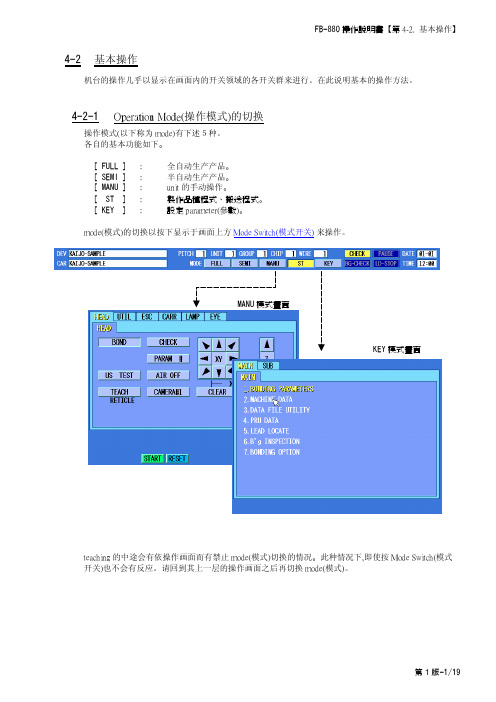
4-2 基本操作机台的操作几乎以显示在画面内的开关领域的各开关群来进行。
在此说明基本的操作方法。
4-2-1 Operation Mode(操作模式)的切换操作模式(以下称为mode)有下述5种。
各自的基本功能如下。
[ FULL ] : 全自动生产产品。
[ SEMI ] : 半自动生产产品。
[ MANU ] : unit 的手动操作。
[ ST ] : 製作品種程式、搬送程式。
[ KEY ] :設定parameter(參數)。
mode(模式)的切换以按下显示于画面上方Mode Switch(模式开关) 来操作。
teaching 的中途会有依操作画面而有禁止mode(模式)切换的情况。
此种情况下,即使按Mode Switch(模式开关)也不会有反应。
请回到其上一层的操作画面之后再切换mode(模式)。
KEY 模式畫面4-2-2 B’g Mode(焊线模式)的切换B’g Mode(銲線模式)有下述6個。
各自的基本功能如下。
BONDBOND :一般的B’g(焊线)。
CHECKCHECK : 仅往B'g 点(焊点)移动。
不B’g(焊线)。
RUNNINGRUNNING : 仅执行B’g(焊线)的对位。
Z轴在search 高度折返不执行B’g(焊线)。
不spark(放电结球)。
STEPSTEP : 虽执行B’g(焊线)动作,但在每个B'g Sequence(焊线程序)停止。
NO-SPARKNO-SPARK: 虽执行B’g(焊线)动作,但不spark(放电结球)。
CYCLECYCLE : 虽执行B’g(焊线)动作,但在每条wire 停止。
B’g Mode(焊线模式)的切换以[BOND][CHECK]两个开关来执行。
有効的只有1个。
被选择的B’g Mode(焊线模式),在画面上的开关为按下状态会显示。
按[BOND]开关随时可切换到BOND Mode(模式)。
按[CHECK]开关随时可切换到非BOND Mode(模式)。
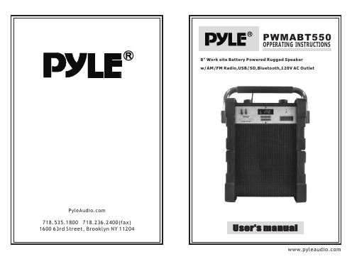
Pyle Audio PWMABT550 8英寸工地电源驱动的耳机说明书
3
4
BLUETOOTH playback
You can connect your Bluetooth phone or other device to the PA speaker. 1. Turn on the unit. 2. Press the INPUT button which is located on top control panel, next to the USB/SD slot. 3. The Bluetooth is on when you hear two “tone” indicator sound. 4. Use your Bluetooth phone or other device to search for the PA speaker. It will displayed as PYLE SPEAKER. 5.Connnect your devices with PYLE SPEAKER,it will pair with unit automatically. 6.You do not need code and get connected with unit. 7.Play music on your phone or device, sound will come from the speaker through the BLUETOOTH wireless connection. 8.You can use the VOLUME/BASS/TREBLE to adjust the sound level for BLUETOOTH, also you can adjust the Bluetooth music sound through your own phone or other device. NOTES: If there is no sound through the PA speaker during Bluetooth, Check the volume controller both on the unit and on your phone or other device.
Door King IPB-Model 9210-080 电动门闸机说明文件说明书

73X194251316252312913132X 2X3X 3X 6X 3X52402X Not Shown 2132112212252273003222X 4X4X2X 2493184X 4X 838179717773270283316677567Typ 2X 2X 2X 2833163X85676767Typ TypREVISIONSREVDESCRIPTION DRW APPR C Added Items 2,75,77,91,180,195,197,199. Revised Qty Items 108,161,179 Was: 3,17,15.Sal 01/23/09 D.C.01/23/09IPB-Model 9210-0801HP, 115V, Chain No. 50SCALE:1:12THE INFORMATION CONTAINED IN THIS DRAWING IS THE SOLE PROPERTY OF Door King . ANY REPRODUCTION IN PART OR AS A WHOLE WITHOUT THE WRITTEN PERMISSION OF Door King IS PROHIBITED.9210-880SIZE DWG A REV SHEET 1 of 8PROPRIETARY AND CONFIDENTIAL C1. Items 2- 4 Not Shown.Notes: Unless Otherwise Specified.Item Part Number Qty UM Description Rev 19210-8801EA IBP-Slide Gate Operator 1HP 115V C 29210-0651EA Manual for Model 921039210-1431EA Wire Set 9210 Sngle Phase49210-0441EA Wire Harness 9210 Subassy SSR59200-9051EA Housing-9210-924072600-9201EA Baseplate 92092600-9191EA Bracket Idler Left Model 920112600-9181EA Bracket Idler Right Model 920132600-9231EA Bracket Idler Left Model 920152600-9241EA Bracket Idler Right Model 920172600-3352EA Idler Bushing 9200192600-3942EA Idler Wheel UHMW Model 9200212600-9711EA Bracket Gear Box Left Mod 920232600-9721EA Bracket Gear Box Right Mod 920252600-3481EA Gearbox Model 920/9200272600-3561EA Sprocket Hub for 920 P1x1 1/4"292600-3951EA Sprocket H50P25 50 Chain311200-0101EA Hinge Bearing332600-3171EA Sprocket 25 th 1 1/4" Bore #35352600-3161EA Sprocket 19 th 3/4" Bore #35379200-4211EA Chain #35 21" 56 Links Length392600-4791EA Chain Master Link #35412600-2781EA Motor 1HP CFce PSC 1725 115V1P502600-8801EA Hole Plug Plastic for 3/8 Hole512600-5711EA Bracket Crank Tube Supp 9200522600-5721EA Bracket Crank Tube 9200532600-7291EA Gasket 9200 Hand Crank542600-5701EA Bracket Crank Tube Frame 9200552600-5251EA Bracket Crank Tube Cover 9200562600-5261EA Bracket Cam Stop 9200572600-5271EA Bracket Limit Switch 9200581804-0243EA Switch Micro No NC C592600-8752EA Capacitor Mounting Clamp602600-1022EA Capacitor 50uf 370VAC619210-1972EA Resistor Assembly Bleeder 22k674001-0354EA Lock N16058BDxSFx2K Key 16120691702-5091EA Bracket Lock Cam 9200712600-7311EA Gasket Switch Cover732600-5331EA Switch Cover Doorking Lockable751702-5011EA Cam 7/8"772599-0511EA Label - Mylar 9000 Series Oper791601-0411EA Switch Toggle SPST 2POS811506-0711EA Tone Generator Loud831812-0051EA Switch Push Button N.O.851702-5151EA Cam Offset912600-6396EA Wire Clamp-1"1012600-5291EA Bracket Limit Enclosure 92001032600-9091EA Shaft Limit Threaded 92001042600-2462EA Limit Nut1052600-2481EA Limit Nut w Magnet Assembly1062600-4544EA Bearing Holder Plastic Front1072600-4404EA Bearing Used in Slide Oper1082600-0968EA Washer SS 1.125"ODx.75"IDx.03" 1119210-3031EA Bracket Partial Open Limit 1121601-2561EA Switch Magnetic Sensor 1132600-1991EA Shaft Limit Cross 92001142630-0181EA Snap Ring 3/4" 011211152600-0322EA Spirol Pin - 3/16" D x 1" L SS 1162600-3092EA Gear Bevel 15 tooth Bored 3/4" 1172600-5221EA Bracket Limit Hold 9200 1182600-8573EA Spring-Compression Limits 1212600-2411EA Chain Guard 92001239200-0051EA Cover Plastic Limits1339200-9001EA Mount Plate PCB Hinged 9200 1359200-9131EA Mount Panel PCB 92001369210-0061EA Cover Plastic1379200-9251EA Mount Plate Solid State Relays 1399200-9323EA Solid Ste Rely 1P SGDH2544RD3 1432600-9451EA Cover Plastic Insulator1451200-0282EA Outlet Snap-In Leviton 1306 1472600-7498EA Wire Connector STA-KON RC6 1492600-4311EA Marker Strip Silkscreened 910 1513130-0081EA Terminal Block 5 pin1533129-0051EA Terminal Block Cover 5 Positio 1552600-4391EA Washer Cup - Brass1572599-0061EA Decal SUPPLY GND1582599-0141EA Decal Copper Wire Only 1592599-0081EA Label Patent1612600-81019EA Bushing 7/8 Poke Thru Flaps 1634404-0101EA PCB Gate Operator1674001-0201EA Terminal 20 Pin1694001-0211EA Key Polarizing Tyco 1437410-5 1709200-2341EA Bracket High/Low Volt Separatr 1712343-0101EA PCB Current Sensor1752600-4141EA Terminal Block-2 Position 1773129-0021EA Terminal Block Cover 2 Positio 1792600-61914EA Wire Clp-5/8" Concord 770-1209 1801804-0293EA Mount Wire Tie1841804-03118EA Tie Wrap 4"1939240-9271EA Door Model 9210 Stainless 1944001-0187FT Weather Stripping 50' rolls 1952600-7321EA Nameplate Plastic DKS1971897-0522EA Gasket, Microphone Support 1992802-0402EA Washer Push on Clamp 2011702-5031EA Cam 1.1/42032600-1931EA Crank Handle Model 9200 2052600-2143EA Spring Clip For Crank Handle 2112599-0341EA Label Gate Operator2132599-1991EA Label Universal2212600-4851EA Chain #50 20' +Master Link 2252616-8152EA Stud Fully Threaded 3/4x10x6" 2272600-9692EA Bracket Chain 920 Zinc Plated 2402599-1002EA Sign Warning2492615-6524EA Bolt Carriage 5/16-18 x 5/8 2502615-68112EA Bolt Carriage 1/2"x13x1"2512615-6052EA Bolt Carriage 10-32 x 1/2 2522615-6255EA Bolt Carriage 1/4-20 x 1/2 2532615-6962EA Bolt Carriage 1/2-13 x 4" 2542615-6786EA Bolt Carriage 3/8-16 x 1 2552615-15416EA Bolt Hex Head 5/16-18 x 1 2562615-0528EA Bolt Hex Head 3/8-16 x 1 2572615-0022EA Bolt Hex Head 1/4x20x1/2length 2592615-67712EA Bolt Carriage 3/8-16 x 3/4 2602616-00010EA Screw Phillips Head 6-32 x 1/4 2612600-8872EA Screw Nylon Phillips 6-32x1/4" 2652616-1036EA Screw Pan Head 4-40 5/8" 2662616-00313EA Screw Phillips Head 6-32 x 3/4 2671816-0392EA Screw 10-32 x 1/4"2692616-0178EA Screw Phillips Head 8-32 x 3/8 2702616-0524EA Screw Phillips Head 10-32 x1/2 2712616-0312EA Screw Flat Head #0-90x1/4 Slot 2802620-02110EA Washer 1/2 " SAE2812802-0034EA Washer #8 SAE2822802-0021EA Washer #6 SAE2832620-0105EA Washer #10 SAE2902620-05014EA Lockwasher 1/2"2912620-04728EA Lockwasher 3/8"2922620-0533EA Lockwasher 5/16"2932620-1092EA Washer 1/4" Split Lock3002620-0364EA Washer 1.483 ODx.813 IDx.116 T 3122620-40912EA Nut Hex Flange Lock 1/4-20 3132902-0045EA Nut Nylon Lock 8-323142620-42014EA Nut Hex 1/2-133152620-40510EA Nut Hex 3/8-163162902-0069EA Nut Nylon Lock 10-323182620-41120EA Nut Hex Flange Lock 5/16-18 3192902-00324EA Nut Nylon Lock 6-323202902-0101EA Nut Nylon Lock 8-32 Green 3222620-4304EA Nut Hex 3/4"x103232620-3992EA Nut Hex 00-90 Brass Zinc Plt。
高速2口径阀门说明书

Doc. no.SX10-OMR0002-AHigh Speed 2 Port ValveSX10 SeriesSafety Instructions ..................................................................................... 2,3 Design (4)Selection (4)Mounting (4)Wiring (4)Lubrication (5)Air Supply (5)Operating Environment (5)Maintenance (5)Precautions (6)Continuous Energization (6)Energizing Time and Non-Energizing Time (6)Others (6)Lead Wire Connection (6)Symbol (6)Wiring (6)Control method (7)Trouble shooting ······················································································· 8,9-1-Safety InstructionsThese safety instructions are intended to prevent hazardous situations and/or equipment damage.These instructions indicate the level of potential hazard with the labels of “Caution,” “Warning” or “Danger.” They are all important notes for safety and must be followed in addition to International Standards (ISO/IEC)*1), and other safety regulations.*1) ISO 4414: Pneumatic fluid power -- General rules relating to systems. ISO 4413: Hydraulic fluid power -- General rules relating to systems.IEC 60204-1: Safety of machinery -- Electrical equipment of machines .(Part 1: General requirements)ISO 10218-1992: Manipulating industrial robots -Safety. etc.Caution Caution indicates a hazard with a low level of risk which, if not avoided, could resultin minor or moderate injury.Warning Warning indicates a hazard with a medium level of risk which, if not avoided, could result in death or serious injury.DangerDanger indicates a hazard with a high level of risk which, if not avoided, will resultin death or serious injury.-2-Safety InstructionsLimited warranty and Disclaimer/Compliance RequirementsThe product used is subject to the following “Limited warranty and Disclaimer” and “Compliance Requirements”.Read and accept them before using the product.Limited warranty and Disclaimer1.The warranty period of the product is 1 year in service or 1.5 years after the product is delivered, whichever is first.∗2)Also, the product may have specified durability, running distance or replacement parts. Please consult your nearest sales branch.2. For any failure or damage reported within the warranty period which is clearly our responsibility,a replacement product or necessary parts will be provided.This limited warranty applies only to our product independently, and not to any other damage incurred due to the failure of the product.3. Prior to using SMC products, please read and understand the warranty terms and disclaimers noted in the specified catalog for the particular products.Compliance Requirements1. The use of SMC products with production equipment for the manufacture of weapons of massdestruction (WMD) or any other weapon is strictly prohibited.2. The exports of SMC products or technology from one country to another are governed by therelevant security laws and regulations of the countries involved in the transaction. Prior to the shipment of a SMC product to another country, assure that all local rules governing that export are known and followed.CautionSMC products are not intended for use as instruments for legal metrology.Measurement instruments that SMC manufactures or sells have not been qualified by type approval tests relevant to the metrology (measurement) laws of each country.Therefore, SMC products cannot be used for business or certification ordained by the metrology (measurement) laws of each country.-3-SX10-OMR0002-ADesign/Selection1. Review the specifications.The product is designed for use only in compressed air systems. Do not operate at pressures or temperatures, etc., beyond the range of specifications, as this can cause damage or malfunction. (Refer to the specifications shown in the catalog.) Please contact SMC if using for fluids other than compressed air. We do not guarantee against any damage if the product is used outside of the specification range.2. VentilationProvide ventilation when using a valve in a confined area, such as in a closed control panel. For example, install a ventilation opening, etc. in order to prevent pressure from increasing inside of the confined area and to release the heat generated by the valve.3. Disassembly and modification is prohibited.Do not disassemble the product or make any modifications, including additional machining.This may cause human injury and/or an accident.4. Air qualityUse clean air.Do not use compressed air that contains chemicals, synthetic oils, including organic solvents, salt or corrosive gases, etc., as it may cause damage or malfunction.For detailed information regarding the quality of the compressed air described above, refer to SMC's "Air Cleaning Systems".5. Ambient environmentUse within the operable ambient temperature range. After confirming the compatibility of the product's component materials with the ambient environment, operate such that fluid does not adhere to the product's exterior surfaces.6. Countermeasures against static electricityTake measures to prevent static electricity since some fluids can cause static electricity.1. Leakage voltageWhen a resistor and a switching element are used in parallel or C-R device (surge voltage suppressor) is used for the protection of the switching device, note that leakage voltage will increase because earth leakage current passes through the resistor and C-R device. The suppressor residual leakage voltage should be 0.2 VDC or less.2. Low temperature operationWhen using the valve in a low temperature condition, take appropriate measures to avoid freezing of thedrainage, moisture, etc. at low temperatures. Unless specified, the valvecan be used down to -10oC.3. Mounting orientationMounting orientation is not specified.Mounting1. Operation Manual (this copy)Install and operate only after reading the operation manual carefully and understanding the contents.Keep the manual handy, so that it can be referred to as necessary.2. Maintenance spaceWhen installing the products, allow access for maintenance.3. Observe the tightening torque for screws.Tighten the screws to the recommended torque, when mounting the product.4. If air leakage increases or equipment does not operate properly, STOP operation.After installation and maintenance, apply air and power supplies to the equipment and perform appropriate functional and leakage inspections to make sure the equipment is mounted properly.5. Painting and coatingWarnings or specifications printed or labeled on the product should not be erased, removed or covered.Please consult with SMC before applying paint to resinous parts, as this may have an adverse effect due to the solvent in the paint.6. Do not apply external force to the coil section.7. Do not warm the coil assembly with a heat insulator, etc.Use tape, heaters, etc., for freeze prevention on the piping and body only. Heating the coil may burn it out.8. When there is a vibration source close to the product, take anti-vibration measures.Wiring1. Polarity.Valves of this series can be either polarity.2. External force applied to the lead wireExcessive force to the lead wire may cause a broken wire. Make sure that no excessive force larger than 15 N is applied to the lead wires.SX10 SeriesPrecautions 1Be sure to read this before handling.Lubrication1. LubricationDo not supply oil.Air Supply1. Type of fluidsPlease consult with SMC when using the product in applications other than compressed air.2. Large amount of condensateCompressed air containing a large amount of condensate can cause malfunction of pneumatic equipment. An air dryer or water droplet separator should be installed upstream from filters.3. Draining controlIf condensate in the drain bowl is not emptied on a regular basis, the condensate will overflow and enter the compressed air lines. This will cause a malfunction of pneumatic equipment. If the drain bowl is difficult to check or remove, installation of a drain bowl with an auto drain option is recommended.4. Use clean air.Do not use compressed air that contains chemicals, synthetic oils, including organic solvents, salt or corrosive gases, etc., as it can cause damage or malfunction.For detailed information regarding the quality of the compressed air described above, refer to SMC's "Air Cleaning Systems".1. If ultra dry air is used as a fluid, the lubrication characteristics of the equipment will deteriorate and this can affect the reliability (life) of the product. Contact SMC beforehand, if using ultra dry air.2. Install air filters.Install air filters close to valves on the upstream side.It is strongly recommended to use a filter with a filtration rating of 0.01 μm or less. Be careful to prevent the supply pressure to the valve from decreasing.3. Take appropriate measures to ensure air quality, such as by providing an after cooler, air dryer, or water separator.Compressed air that contains excessive drainage may cause malfunction of valves and other pneumatic equipment. Therefore, take appropriate measures to ensure air quality, such as by providing an after cooler or water separator.4. If excessive carbon powder is seen, install a mist separator on the upstream side of the valve.When the amount of carbon particles generated from the compressor is excessive, they will stick inside of the valve, and may cause malfunction or internal leakage.Refer to SMC’s Best Pneumatics catalog for further details on compressed air quality.Operating environment1. Do not use in an environment where corrosive gases, chemicals, sea water, water or steam are present.2. Do not use in an atmosphere containing flammable or explosive gases. Fire or an explosion can result. The product is not designed to be explosion proof.3. Do not operate in a location subject to vibration or impact.4. The valve should not be exposed to prolonged sunlight. Use a protective cover, if necessary.5. Shield the product from radiated heat generated by nearby heat sources.6. Employ suitable protective measures in locations where there is contact with oil and welding spatters, etc.7. When the solenoid valve is mounted onto a control panel and energizing time is long, take measures against radiation in order to keep the valve temperature within the specified range.Maintenance1. Maintenance should be performed according to theprocedure indicated in the Operation Manual (this copy).Improper handling may cause an injury, damage and/or malfunction of equipment and machinery.2. Low frequency operationOperate valves at least once every 30 days to prevent malfunction. (Refer to the precautions for "Air Supply" and follow the instructions)3. Removal of productValves will reach high temperatures after operation. Confirm that the valve temperature has lowered sufficiently, before removing the product. If touched inadvertently, there is a danger of being burnt.1. Shut off the fluid supply and release the fluid pressure in the system.2. Shut off the power supply.3. Remove the product.1. Discharging condensate Exhaust the drainage from an air filter periodically.2. Filter1. Make sure that the filer is not clogged.2. Replace filter elements after a year of use, or earlier if the pressure drop reaches 0.1MPa.3. StorageIn case of long term storage after use with heated water, thoroughly remove all moisture to prevent rust and deterioration of rubber materials, etc.SX10 SeriesPrecautions 2Be sure to read this before handling.Precautions1. Valves will reach high temperatures duringoperation.Use caution, as there is a danger of being burnt if a valve is touched directly.Continuous Energization (24 VDC)1. Power consumption 80 W specification: Not possibleWhen operating with an energy saving driver, continuous energization with the holding voltage of 3to 6 VDC is possible.2. Power consumption 40 W specification: Not possibleWhen operating with an energy saving driver, continuous energization with the holding voltage of 4to 8 VDC is possible.3. Power consumption 10 W specification: Please consult with SMC.When operating with an energy saving driver, continuous energization with the holding voltage of 8to 16 VDC is possible.4. Power consumption 4W specification: Possible Energizing Time and Non-Energizing Time(Without using an energy saving driver)1. Non-energized time (OFF) must be set longer than the energized time (ON).2. For use with voltages other than 24 VDC, please consult with SMC and provide the operating condition information of pressure, voltage, energizing time and non-energizing time.Others1. If the valve is energized without air supply, the coil may be burned. Make sure to supply pressure to the valve when energizing.2. Please contact SMC for the product usage with a voltage exceeding 75 VDC. Standard required by CE mark is different.Lead Wire ConnectionConnect the lead wires to those specified.SymbolWiring1. Use electrical circuits which do not generate chatteringin their contacts.2. Keep the voltage at +24 VDC, +/-5%.3. Driving circuitCircuit and elements used for the output will significantlyinfluence the product performance. Heat generation,response characteristics, etc. need to be examinedbefore using.4. Using a surge voltage suppressor such as diode andsurge absorber for the electric circuit may causemalfunction, such as delay in response, abnormal heatgeneration or burn out of the coil. Please consult withSMC when using it.Use elements that are resistant to the surge voltage specifiedbelow for the output.Surge voltage: 300 VSX10 SeriesPrecautions 3Be sure to read before using.BlackBlackLead wire colorControl Method (Operation example with anenergy saving driver circuit)1. Control with 2 power supplies, starting power supply and holding power supplySwitching system from high voltage to low voltage2. High speed switching control of high voltage by PWM controlSX10 SeriesPrecautions 4Be sure to read before using.If any failure is found during operation, please check and take measures in accordance with the procedure below.Phenomenon Possible causes CountermeasureOperation failure Flow does not start. Non-conformance of electricsystem- Incorrect wiring- Fuse blown out, lead wirebrokenCheck each part and take correctiveactions for the failed part.Voltage dropCheck the supply voltage. Take correctiveactions if voltage drop is confirmed. Keepthe voltage at +24 VDC, +/-5%.Supply pressure is too high.Check if the supply pressure is out of thespecification range.Coil is damaged.Energizing time is too long.Check if the energization conditions areout of the specification range. This producthas a limitation for the energization time.(See page 6)Usage of a surge voltagesuppressorWhen a protective circuit, such as diodeand surge absorber is used, the coil mayreach an abnormally high temperature andburn. Use a circuit and elements that areresistant to surge voltage. (See page 6)Fluid temperature andambient temperature are toohigh.Check that the fluid temperature and theambient temperature are within thespecification range. When valves aremounted next to each other, keep adistance of at least 0.5 mm between thevalves.The valve does notclose.Air piping is connected in thereverse direction.Connect the piping so that 1 (N) port is onthe upstream side.Foreign matter enters orbecomes lodged in piping.Clean the supply air by using filters.(Recommended filtration rating: 0.01 μm)Residual voltage is too high.Check the residual voltage.The suppressor residual voltage should be0.2 VDC or less.Downstream side flow of thevalve is restricted.When flow on the downstream side isrestricted, the valve may not close due toback pressure. Adjust the piping.Air leakage Find and check the airleakage point.Air leakage betweenthe valve and baseThe mounting screws areloose.Tighten the mounting screws.Tightening torque: 0.5 to 0.7 NmInterface gasket is wedged.Check that the interface gasket is mountedcorrectly. Check that there is noabnormality with the O-ring such astwisting and/or damage.Air leakage from 2(OUT) portForeign matter is trapped atthe seating surface of thevalve element, causing anincrease in the internalleakage.Replace the valve.Clean the supply air by using filters.(Recommended filtration rating: 0.01 μm) SX10 SeriesTrouble shootingSX10 SeriesTrouble shootingARENEWAL 2018.8 4-14-1, Sotokanda, Chiyoda-ku, Tokyo 101-0021 JAPANTel: + 81 3 5207 8249 Fax: +81 3 5298 5362URL Note: Specifications are subject to change without prior notice and any obligation on the part of the manufacturer.© 2018 SMC Corporation All Rights ReservedNo.SX10-OMR0002-A。
BOKER 数字智能广播系统使用手册
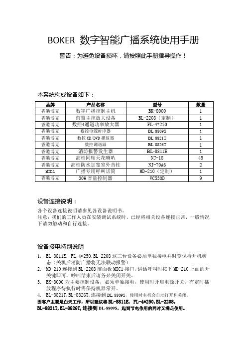
BOKER数字智能广播系统使用手册警告:为避免设备损坏,请按照此手册指导操作!本系统构成设备如下:品牌产品名称型号数量香港博克数字广播控制主机BK-8000 1 香港博克前置主控放大设备BL-2208(定制) 1 香港博克数控4通道功率放大器FL-4*250 1 香港博克数控电源时序器BL-8809S 1 香港博克数控CD/DVD播放器BL-8821T 1 香港博克数控调谐器BL-8826T 1 香港博克消防报警发生器BL-8811E 1 香港博克高档同轴天花喇叭NJ-18 45 香港博克高档防水加宽室外音柱NJ-70A6 2 MIDA 广播专用呼叫话筒MD-210(定制) 1 香港博克30W音量控制器VC530D 9设备连接说明:各个设备连接说明请参见各设备说明书。
注意:我们的工作人员在安装调试系统时,已经将相关设备连接正常,一般情况下请勿触动和自行连接。
设备接电特别说明1.BL-8811E, FL-4*250,BL-2208这三台设备必须单独接电并时刻保持开机状态(关机后消防广播将无法联动报警)2.MD-210连接到BL-2208前面板MIC1接口,讲话呼叫时按下MD-210上面的开关键即可,呼叫结束后请务必关闭开关。
3.BK-8000为主要控制设备,必须单独接电,使用时开启电源开关,有定时播放程序待执行时需保持机器常开。
4.BL-8821T,BL-8826T,连接到BL-8809S,使用时主机会自动打开和关闭。
因客户主要是白天工作,所以建议将BL-8811E, FL-4*250,BL-2208,BL-8821T,BL-8826T,连接到BL-8809S,起到节电作用的同时又满足使用。
如何手动播放音乐如何用DVD或调谐器给指定区域播放音乐?首先在保证FL-4*250,BL-2208,BK-8000开启的情况下,按BK8000上的MENU按键,输入密码(默认:0000)进入系统;按BK8000上的“DOWN”和“UP”按键滚动菜单,选择“即时操作”后按“CERTAIN”键进入,然后选择“开启电源”再按“CERTAIN”键确认。
Hobbywing Xerun BANDIT G2 高功率电动机说明书
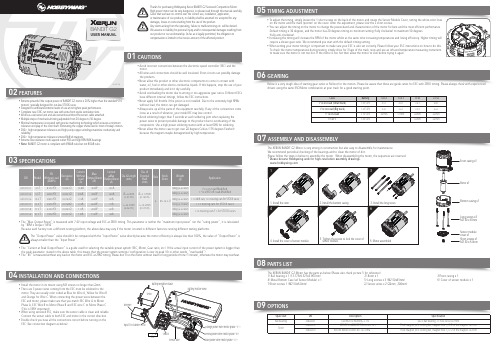
02FEATURES05USER MANUALBANDIT G2• Extreme powerful (the output power of BANDIT G2 motor is 20% higher than the standard V10 motors), specially designed for out-law STOCK races.• Designed to withstand extreme levels of use at its highest peak performance.• Complete new CNC cut motor case with extra front spoke ventilation slots.• Works as a sensored unit and also sensorless without the sensor cable attached.• Multiple steps of mechanical timing adjustable from 20 degree to 50 degree.• Minimal maintenance is required with precise machining technology which ensures a minimum tolerance end play of the rotor shaft. Eliminating the copper shims used in most of today’s motors. • 200℃ high temperature tolerance and high purity copper windings maximize conductivity and reliability.• 200℃ high temperature tolerance sintered NdFeb magnets.• Extreme low resistance multi-layered outlet PCB and high RPM NSK bearings.• Note: BANDIT G2 motor is compliant with IFMAR rules but not ROAR rules.components. Use a high power soldering station with at least 60W for soldering.• Never allow the motor case to get over 80 degrees Celsius (176 degrees Fareheit) because the magnets maybe demagnetized by high temperature.• Install the motor in its mount using M3 screws no longer than 8mm.• There are 3 power wires coming from the ESC must be soldered to the motor. They are usually color coded as Blue for Wire A, Yellow for Wire B and Orange for Wire C. When connecting the power wires between the ESC and motor, please make sure that you match ESC Wire A to Motor Phase A, ESC Wire B to Motor Phase B and ESC wire C to Motor Phase C (This is VERY important).• When using sensored ESC, make sure the sensor cable is clean and reliable. Connect the sensor cable to both ESC and motor in the correct direction.• Double check you have all the connections correct before turning on the ESC (See connection diagram as below).ServoBattery Positive (Red)Battery Negative (Black)07ASSEMBLY AND DISASSEMBLYThe XERUN BANDIT G2 Motor is very strong in construction but also easy to disassemble for maintenance. We recommend periodical checking of the bearings and to clean the motor of dirt.Please follow the steps in below to assemble the motor. When disassembling the motor, the sequences are reversed.* Please browse Hobbywing web for high-resolution assembly drawings. Rotor x1Front casing x1Bottom casing x1Long screws x3M2.50 x 45mmSensor module cover x1Short screws x1M2.50 x 6.0mmTIMING ADJUSTMENT03SPECIFICATIONS04INSTALLATION AND CONNECTIONSThe “Output Power” value shouldn’t be compared with the “Input Power” value directly because the motor efficiency is always less than 100%, the value of “Output Power” is always smaller than the “Input Power” .• The “Max. Output Power” is measured with 7.4V input voltage and ESC at ZERO timing. This parameter is neither the “maximum input power” nor the “rating power”, it is calculated by “RPM x Torque / 9550”.Because each factory runs a different testing platform, the above data may vary if the motor is tested in different factories running different testing platforms.• The “Current at Peak Output Power” is a guide used for selecting the suitable power system (ESC, Motor, Gear ratio, etc.) If the actual input current of the power system is bigger than the peak parameter stated in the above table, this means that the power system settings / configuration is over its peak (Or in other words, “overloaded”)• The “KV” is measured without any load on the motor and ESC at ZERO timing. Please don’t run the motor without load for long periods of time (1 minute), otherwise the motor may overheat.The XERUN BANDIT G2 Motor has the parts as below (Please also check picture 5 for reference).1) Ball bearing x 1 (13.175x9.525x3.967mm) 2) Rotor x 1 3)Front casing x 14) Metal Bottom Case (w/ Sensor Module) x 1 5) Long screws x 3 (M2.50x45mm) 6) Cover of sensor module x 1 7)Short screws 1 (M2.50x6.0mm) 8) Sensor wires x 2 (80mm, 200mm)08PARTS LISTdrivers using the same ESC/Motor combination at your track for a good starting point.09OPTIONSPN Spare Part DescriptionSpecificationBall bearing 30820001540 MOTOR BEARING-3.175R2ZZ Ball Bearing, 3.175x9.525x3.967mm30820012XERUN-V10&BANDIT-Rotor-Φ5-12.1Thick magnet, w/o cooling fan, magnet hole 5, O.D. of the magnet :12.1mm 30820010XERUN-BANDIT-Rotor-Φ5-12.3-UltraThick magnet, w/o cooling fan, magnet hole 5, O.D. of the magnet :12.3mmRotor10.8A 400W 125A Current Without Load(A)Max.Output Power(W)Current@Max.Output Power (A)Dia. & Length(mm)20161126。
