as执行器技术参数
SMC速度控制阀AS系列产品介绍
SMC速度控制阀AS系列产品介绍SMC速度控制阀AS系列作用SMC 速度控制阀AS系列是由单向阀和节流阀并联而成的流量控制阀,常用于控制气缸的运动速度,故称为速度控制阀。
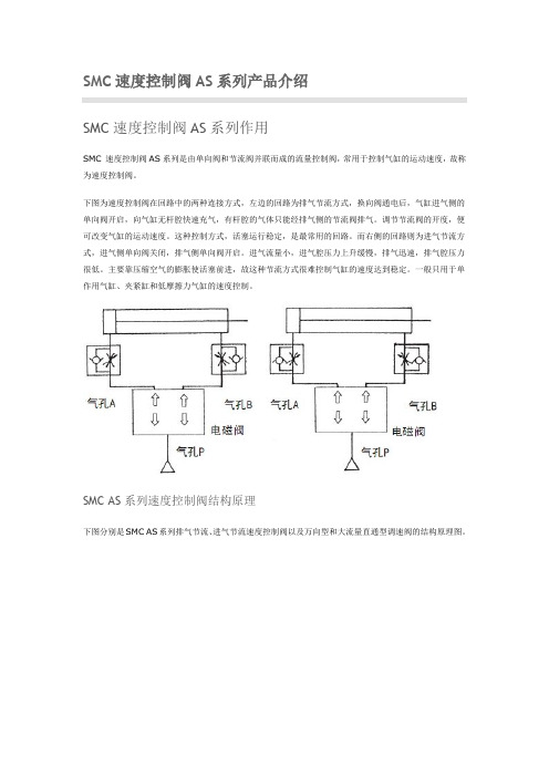
下图为速度控制阀在回路中的两种连接方式,左边的回路为排气节流方式,换向阀通电后,气缸进气侧的单向阀开启,向气缸无杆腔快速充气,有杆腔的气体只能经排气侧的节流阀排气。
调节节流阀的开度,便可改变气缸的运动速度。
这种控制方式,活塞运行稳定,是最常用的回路。
而右侧的回路则为进气节流方式,进气侧单向阀关闭,排气侧单向阀开启。
进气流量小,进气腔压力上升缓慢,排气迅速,排气腔压力很低。
主要靠压缩空气的膨胀使活塞前进,故这种节流方式很难控制气缸的速度达到稳定。
一般只用于单作用气缸、夹紧缸和低摩擦力气缸的速度控制。
SMC AS系列速度控制阀结构原理下图分别是SMC AS系列排气节流、进气节流速度控制阀以及万向型和大流量直通型调速阀的结构原理图。
SMC AS系列速度控制阀系列和分类SMC 速度控制阀的种类繁多。
按安装方式,有直接安装型(接头体靠螺纹连接在气缸通口上,另一端为快换接头或配管)和面板安装型(将调速阀固定在面板上,气路连接为快换接头)。
按气体流动方向,有直通式(进出口在一条线上)、弯头式(进出口方向成90°)和万向型(出口方向可绕进口方向转动)。
按阀体材质分,有金属阀体和树脂阀体。
按功能分,有标准型,带残压释放阀的形式(AS□FE系列)不锈钢阀体形式(AS□FG系列,可用于耐腐蚀的环境中)、低俗控制用的形式(AS□FM系列、10~50mm/s)/洁净环境用的形式(AS□FPG、AS□FPQ系列,用于洁净室)、用选举调节的形式(AS□1F-□D系列)、用专用工具调节的形式(AS□1F-□T系列)。
此外还有双向型速度控制阀ASD系列。
带先导式单向阀的速度控制阀ASP系列。
SMC AS系列速度控制阀主要技术参数参见SMC样本。
SMC AS系列速度控制阀的选用根据速度控制的气缸缸径和对气缸速度变化范围的要求,计算控制流量的范围,然后从产品样本上查节流特性曲线,选择速度控制阀范围的规格。
AS-I总线教程

对于普通I/O设备来说,如果想接入AS-I系统,必须提供一个带有ASIC的AS-I模块,I/O设备与这些模块连接。
·供电电源
供电电源为30VDC,必须使用专用的AS-I电源,并且直接与数据线连接。AS-I从站正常工作的电压至少在26.5V以上。一个从站消耗的电流在100mA以上,一个分支上的所有从站消耗电流大约为2A,AS-I电缆能提供的最大容量为8A。当消耗的电流过大时,需要添加辅助电源。辅助电源为24VDC,用一个双芯黑色无屏蔽的电缆将辅助电源与从站连接起来。辅助电源线同样使用穿刺技术连接。
·具有坚固的网络拓扑,不需要屏蔽和终端电阻,即使在恶劣环境中也能保证通信的可靠性。
·网络中只有1个主站,最多31个从站,每个从站有4位I/O可以利用。
·最多124个I/O传感器和执行器。
·主从站间采用循环方式进行访问。
·循环时间最大5ms。
·网络连接电缆为双芯、非屏蔽、1.5mm²的黄色异型电缆或圆形电缆。最大长度为100m。使用中继器可扩展到300m。但最多只能使用两个中继器。
每个等级的网络都与上下相邻的网络连接,可以判定相互间通讯的需求。在最上层网络,存在众多复杂的计算机系统,能够不定期的对各种复杂数据进行响应,大量的通讯参与者和响应者在网络中相互协调。
在最底层,依然有很大的信息吞吐量,只是数据相对要少于上层结构。
在自动化系统网络中可以分为以下5层结构:
·计划编制层(Planning Level),对来自生产层的信息进行评价,组织编排并协助生产部门进行决策。在这一层中,不论是信息量还是传输速率和距离都是最大的。
AS-I主站采用轮询方式访问,即按照顺序一个一个的对从站进行访问。这个顺序就是在上电时,主站第一次访问时建立的地址列表。如果在访问时,从站在规定时间内没有对主站的请求作出响应,主站会立即重复访问一次。还没有响应的话,主站将访问下一地址。在后面的两个周期内,主站会继续尝试访问先前丢失的地址,如果依然没有回应,故障错误位会被置位,并将该信息发送给PLC。
ASI接口介绍

主站的9种报文内容
报文名称
数据交换 写参数 地址分配 复位 删除地址操作 读I/O配置 读ID编码 状态读取 读出状态和状态删除
主站报文内容
ST SB
5位地址
5位参数
PB EB
0
0
A4 A3 A2 A1 A0
0
D3 D2 D1 D0 PB
1
0
0
A4 A3 A2 A1 A0
1
D3 D2 D1 D0 PB
ASI信息结构
主站请求和从站应答
在ASI主从结构中,主站所发出的报文在系统数据交换中占有重要的 地位。主站的请求报文共有9种:(1)数据交换 要求从站把测量数 据上传给主站,而主站又可以把控制指令下达给从站。(2)写参数 设置从站功能,如传感器的测量范围、激活定时器、在多传感器系统 中改变测量方法等。(3)地址分配 只有当从站地址为00H时才有效。 从站接到这个请求后,用06H回答,表示已收到了主站的正确请求, 从站从此就可以在这个新地址被呼叫了,同时把这个新地址存储在从 站的EEPROM中,这个过程大约需要15ms。这种方式使主站可以对 运行中损坏后重新置换的从站自动进行原有地址的设置。(4)复位 把被呼叫的从站地址恢复到初始状态,从站用06H回答,整个过程需 2ms。(5)删除操作地址 暂时把被呼叫的从站地址改为00H,这个 报文一般和“地址分配”报文一起使用。当新地址确定后,从站用 06H回答。如果使用指令“Reset-ASI-Slave”就可以恢复原地址。 (6)读I/O配置。(7)读ID编码 从站的I/O设置和ID编码在出厂时 已经确定,不能改变。(6)、(7)结合使用的目的是确定从站的身 份。(8)状态读取 读取从站状态缓冲器中的4个数据位,以获得在 寻址和复位过程中出现的错误信息。(9)读出状态和状态删除 读出 从站状态缓冲器的内容,然后删除。
风门执行器

快速风门执行器
系列
旧型号
LMQ.. LMQU24
LMQU24-SR
NMQ.. NMQU24
NMQU24-SR
新型号 LMQ24A LMQ24A-SR NMQ24A NMQ24A-SR
机械式自复位风门执行器
系列
旧型号
新型号
NFA.. NFU
NFA
NFU-S2
NFA-S2
NFU24-SR
NF24A-SR
开关型最大50dB(A) 调节型及三态型最大35dB(A)
开关型最大50dB(A) 调节型及三态型最大30dB(A)
62dB(A)
电缆 1m
L/R安装选择
最大95°,可通过机械限位装置调节
机械指示器
IP42
IP54
CE 遵循 2004/108/EC
CE 遵循 2006/95/EC
-30...+50°C
16
NFA
55
17
NFA-S2
56
18
NF24A-SR
57
19
机械式自复位风门执行器, 20Nm
20
SFA
58
SFA-S2
59
21
SF24A-SR
60
22
机械式自复位风门执行器, 30Nm
23
EF24A-S2
61
24
EF24A-SR
62
25
EF230A-S2
63
26
电子式自复位风门执行器, 40Nm
LF230-S
LF24-3
TF24-SR
LF24-SR
开关型75s;调节型 / 三态型 150s 25s @ -20...+50°C / 最大60s @ -30°C
as系列基础知识问答讲解
基础知识篇Q: 什么是执行器?A: 顾名思义,就是用来执行命令的一种执行装置。
工业生产过程自动调节系统一般由检测器、调节器、执行器和调节对象组成。
其中执行器总是不可缺少,执行器在自动控制系统中的作用相当于人的四肢,它接受调节器的控制信号,改变操纵变量,使生产过程按预定要求正常执行。
一般由执行机构和调节机构(一般称为调节阀)组成。
此外,根据需要还可配上阀门定位器和手轮机构等附件。
Q: 执行机构和调节机构的作用是什么?A: 执行机构是指根据调节器控制信号产生推力或位移的装置,而调节机构是根据执行机构输出信号去改变能量或物料输送量的装置,而调节机构是根据执行机构输出信号只改变能量或物料输送量的装置,最常见的是调节阀。
Q: 现在主流的执行器分类有哪些?A: 执行器按其能源形式分为液动、气动和电动三大类,它们各有特点,适于不同的场合。
随着近几年来科学技术的不断发展各类执行机构正逐步走向智能化的道路,而其中专门和气动执行器配套使用的智能阀门定位器和全电子电动执行器的出现更加速了执行机构智能化的发展,为执行器的应用开辟了新天地。
Q: 液动执行器的特点是什么?A: 液动执行器推力最大,一般都是机电一体化的,但比较笨重,所以现在使用不多。
但也因为其推力大的特点,在一些大型场所因无法取代而被采用,如三峡的船阀用的就是液动执行器。
Q: 气动执行器的特点是什么?A: 气动执行器的执地机构和调节机构是统一的整体,其执行机构有薄膜式和活塞式两类。
活塞式行程长,适用于要求有较大推力的场合,不但可以直接带动阀轩,而且可以和蜗轮蜗杆等配合使用;而薄膜式行程较小,只能直接带动阀杆。
其执行器分为正作用和反作用两种形式,所谓正作用就是信号压力增大,推杆向下;反作用形式就是信号压力增大,推杆向上。
这种执行机构的输出位移与输入气压信号成正比例关系,信号压力越大,推杆的位移量也越大。
当压力与弹簧的反作用力平衡时,推杆稳定在某一位置,气动执行器又有角行程气动执行器和直行程气动执行器两种。
AS选型手册(圣玛特)
放油孔
液晶显示窗口 现场开/关旋钮 控制方式设置旋钮
1.产品描述
SDA 制造的 AS 电动阀门执行器适用于各种类型的电动阀门,如闸阀、球阀、蝶阀、风门、闸板等。 执行器与阀门通过联轴器实现传动,AS 执行器的输出接口符合国际标准。
在不安装第二级减速箱的情况下,AS00-AS35 电动阀门执行器最大可输出 2000N·m 的转矩,或 330kN 的推力。所有 AS 执行器都提供推力型或非推力型联轴器,提供顶部安装手轮,AS30、32、35 可 选带减速器的侧面安装的手轮。
注:1. 虚线表示执行器外盖的拆卸空间;
2. ○△ 表示将安装联轴器的面,执行器通过联轴器来驱动阀门,SDA 提供多种联轴器供用户选择。
AS 系列电动阀门执行器 选型手册
第3页
AS20/AS25 执行器
轴盖(阀门阀杆的行程空间)
端子室
电缆进线口
手动/电动切换手柄 电动机
放油孔
液晶显示窗口 现场开/关旋钮 控制方式设置旋钮
注:1. 虚线表示执行器外盖的拆卸空间;
2. ○△ 表示将安装联轴器的面,执行器通过联轴器来驱动阀门,SDA 提供多种联轴器供用户选择。
第2页
AS 系列电动阀门执行器 选型手册
AS10/AS15 执行器
电缆进线口
轴盖(阀门阀杆的行程空间)
端子室
手动/电动切换手柄 电动机
放油孔
液晶显示窗口 现场开/关旋钮 控制方式设置旋钮
B向
A向
关 开
电缆线进口
B向
W.15min
rpm
日
T 8529-1997
2001
IIBT6 (Iห้องสมุดไป่ตู้C)
月
AUMA A-Series 工业电动执行器说明书

Technical InstructionsDocument No. A6V12035775July 7, 2020A-Series IndustrialElectric Actuators AUMA (21,300 and 40,680 lb-in)Siemens Industry, Inc.DescriptionA-Series Industrial Electric AUMA actuators provide precise, durable control of quarter turn Siemens resilient seat butterfly valves. The compact industrial housing is rated to NEMA 6P (IP 68) standards for outdoor use. All models include integrated controls and a manual override handwheel.The standard AUMA models are 120V single phase. All AUMA actuators include six auxiliary switches, torque switches, a position indicator and a heater. Modulating units provide position feedback as standard. Features• Compact, lightweight design and direct mounting • Manual, declutchable override handwheel • Position and motion indicator lights • Push button controls • CE Certified• On/off or modulating control• Output torque 21,300 lb-in (2,407 Nm) to 40,680 lb-in (4,596 Nm) • ISO 5210 for direct mounting• All actuators include a heater to prevent condensation build-up •All modulating units include a feedback potentiometerOrderingActuators can be ordered separately or together with a valve as an assembly.Product NumbersTable 1. A-Series AUMA Industrial Electric Actuators, 120V.Product Number Operating Mode Voltage 50/60 HzTorque 90° Stroke Time*Current Draw (Amps) (lb-in) (Nm) Full Load LockedRotorA226.21K On/Off120 Vac21,300 2,407 60 sec.6.514A226.41K 40,680 4,596 A266.21K Modulating21,300 2,407 A266.41K40,6804,596* Operating times shown are with 60 Hz power supply. Actuators with 50 Hz power supply will be 20% slowerWarning/Caution Notations WARNING: Personal injury or loss of life may occur if you do not perform a procedure as specified.CAUTION:Equipment damage may occur if you do not perform a procedure as specified.Technical Instructions A-Series Industrial Electric Actuators AUMA Document Number A6V12035775June 15, 2020CAUTION:Do not install or use the A-Series Industrial Electric Actuator in or near environmentswhere corrosive substances or vapors could be present. Exposure of the electricactuator to corrosive environments may damage the internal components of thedevice and will void the warranty.Application These actuators are ideal for use on valves for chillers, cooling towers, boilers, heatexchangers and other outdoor applications. The actuators’ advanced electronicsassure reliable compatibility with virtually any analog control signal used in today’sbuilding automation and temperature control systems. The NEMA 6P rated housingprevents any water ingress in outdoor applications. The built-in heater prevents anycondensation build-up inside the housing.NOTE: Use a “liquid tight” conduit connector to maintain NEMA 6P rating. SpecificationsOperating Conditions Ambient Temperature -22°F to 158°F (-30°C to 70°C)Fail Position Loss of supply power - fail-in-placeDuty Cycle On/Off – 15 min. continuous, max. six starts/minuteModulating – 25% intermittent duty Physical Description Motor 120 Vac, Single-Phase, Reversible, PermanentSplit Capacitor Induction MotorMotor Protection 1 Ph-1 thermal switch 284°F (140°C)Class F insulation, tropicalized windingControl Voltage A226.21K and A226.41K: 120 VacA266.21K and A266.41K:Input 4 to 20 mAModular Power Supply 24 VdcOutput Aux. Voltage A226.21K and A226.41K: 115 Vac – 30 mAA266.21K and A266.41K: 24 Vdc – 100 mAFeedback Signal 4 to 20 mAOutput Contacts 6 Output contacts: 6 NO/NC without common 5AOutput Signals Default setting: Fault, End pos. CLOSEDEnd pos. OPEN, Selector sw. REMOTE, Torquefault CLOSE, Torque fault OPENTerminal StripPower Terminals 8 to 10 AWG (6 to 10 mm2)Controls Contacts 14 AWG (2.5 mm2)Heater 24V Internal Supply (5 Watt)Dimensions See Figure 3 and Figure 4.Weight A2x6.21K – 165 lbs. (75 kg)A2x6.41K – 195 lbs. (88 kg)Enclosure NEMA types 6P (IP68)Corrosion Protection: KSConduit entries Plug/socket 100 mm, 2 × 3/4” NPT; 1 × 1-1/4” NPTManual operation To close the valve, turn handwheel clockwise.Drive shaft (valve) turns clockwise in closedirection. 52:1 drive ratioAngle of Rotation 92° maximumCertifications CE CertifiedCSA - Classes C322102 and C3221812(available upon request)A-Series Industrial Electric Actuators AUMA Technical InstructionsDocument Number A6V12035775July 7, 2020Product NumbersTable 2. Product Numbers.Use the product numbers in the following table to order a valve or a valve and actuator assembly. The valve product number consists of the type, action, valve size, disc type, and valve configuration.To order an assembly, add a (-) after the valve product number and then choose the application, actuator, voltage, control signal, end switches followed by a separator (.) and the actuator torque.Siemens Industry, Inc. Page 3Technical InstructionsA-Series Industrial Electric Actuators AUMADocument Number A6V12035775 July 7, 2020Page 4Siemens Industry, Inc.Mounting and InstallationAll A-Series industrial electric actuators are suitable for direct mounting on Siemens resilient seat butterfly valves.NOTE:The standard mounting position for the actuator is to orient the base of the actuator parallel to the pipeline. •To mount an actuator on a vertical pipe, position the unit with the conduit entries on the bottom to prevent condensation from entering the actuator through its conduits.• Use a “liquid tight” conduit connector to maintain NEMA 6P rating.Service The resilient seat butterfly valve and actuator are maintenance-free.WiringCAUTION: •When wiring an A-Series Industrial Electric Actuator for two-position(on/off) control and the power to the actuator is commanded to be off, you must ensure that there is no extraneous or leakage voltage between hot and common. Leakage voltage greater than 3 Vac can cause actuator failure.• When wiring an A-Series Industrial Electric Actuator for two-positioncontrol, the controller should use at minimum a one-second time delay for command signal reversal. Instantaneous command reversals may cause actuator failure.Figure 1.. On/Off .NOTE:Use this A-Series Industrial Electric Actuator only to control equipment under normal operating conditions. Where failure or malfunction of the electric actuator could lead to personal injury or property damage to the controlled equipment or other property, additional precautions must be designed into the control system. Incorporate and maintain other devices such as supervisory or alarm systems or safety or limit controls intended to warn of, or protect against, failure or malfunction of the electric actuator.Figure 2. Modulating.A-Series Industrial Electric Actuators AUMA Technical InstructionsDocument Number A6V12035775July 7, 2020 Information in this publication is based on current specifications. The company reserves the right to make changes in specifications and models as design improvements are introduced. Products or company names mentioned herein may be the trademarks of their respective owners. © 2020 Siemens Industry, Inc.Siemens Industry, Inc. Smart Infrastructure1000 Deerfield Parkway Buffalo Grove, IL 60089 USA + 1 847-215-1000Your feedback is important to us. If you havecomments about this document, please send themto***************************************Document No. A6V12035775Printed in the USAPage5of 5DimensionsFigure 3. Model A2x6.21K Actuators.Figure 4. Model A2x6.41K Actuators.。
成都圣玛特AS使用说明书.doc
3.1 手动操作 ........................................................................................................................................ 3 3.2 电动操作 ........................................................................................................................................ 3
5 安装执行器 ......................................................... 10
5.1 将执行器安装到丝杆驱动的阀门上........................................................................................... 10 5.2 将执行器安装到键驱动的阀门上............................................................................................... 10 5.3 手轮密封 ...................................................................................................................................... 10
电动执行器性能及技术参数

精密的蜗轮蜗杆机构可高效传输大扭矩,效率高,噪音低(最大50分贝),寿命长;有自锁功能,防止反 转,传动部分稳定可靠,无需再加油。 2.9防脱螺栓
拆除外壳时,螺栓附在壳体上,不会脱落。 2.10安装
底部安装尺寸符合 ISO5211/ DIN3337国际标准,孔成双四方形便于带方杆的阀线性或45°转角安装,适 应性强。可以垂直安装,也可以水平安装。 2.11线路
27×27 Φ31.65 90
27×27 Φ31.65 180
27×27 Φ31.65 180
Max φ65
180
Max φ65
180
Max φ65
180
0.33
13.8
0.33
14
0.47
14.3
0.47
60
0.85
60
0.85
60
0.85
60
四、标准件技术参数 外壳
防水级别 IP67,NEMA4 and 6
电机电源
110/220V AC 单相,380/440V AC 3相, 50/60Hz, ±10%
控制电源
110/220V AC 单相,50/60 Hz, ±10%
控制信号
输入输出4-20mA
电机
鼠笼式异步电机
限位开关
2 X 开/关, SPDT,250V AC 10A
辅助限位开关
2 X 开/关, SPDT,250V AC 10A
外观
6.直流标准开关无源触点信号输出线路图
精小型电动执行器接线图
请分开连接电动执行器的动力线 路,切勿用同一接点去控制数台电 动执行器,以免造成失控和电机过 热。
ASI接口介绍

读ID编码
状态读取 读出状态和状态删除
0
0 0
1
1 1
A4
A4 A4
A3
A3 A3
A2
A2 A2
A1
A1 A1
A0
A0 A0
1
1 1
0
1 1
0
1 1
0
1 1
1
0 1
PB
PB PB
1
1 1
ASI传感器与一般传感器的区别
如图
注:ASI传感器信号不可短接,否则会烧坏。
ASI信号干扰
ASI总线尽可能与其他电源线混装在一起
ASI报警信息
谢
谢 !
访问方式和报文
ASI总线系统为主从结构,采用请求-应答的访问方式。 主站先发出一个请求信号,信号中包括从站的地址。接 到请求的从站会在规定的时间内给予应答,在任何时间 只有1个主站和最多31个从站进行通信。一般访问方式 有两种:一种是带有令牌传递的多主机访问方式;另一 种是CSMA/CD方式,它带有优先级选择和帧传输过程。 而ASI的访问方式比较简单,为了降低从站的费用、提 高灵活性,一方面在不增加传输周期的条件下尽量包括 更多的参数和信息,另一方面传输周期的时间应能自动 调整,例如系统中只有6个从站时,传输周期为1ms, 而有31个从站时周期约为5ms。如果在网上有短暂的 干扰时,主站没有收到从站的应答信号或收到的是错误 无效的信号时,主站可以重发信息而无需重复整个传输 周期。
数据解耦电路
数据解耦电路由两个50μH的电感和两个 39Ω的电阻相互并联组成,通过电感可以将 传输信号的电流脉冲转变为电压脉冲,同时 它还有防止数据传输频率信号经过电源而造 成短路的作用,两个电阻代表了网络边界终 端。为使电路信号噪声最低,必须采用高对 称性的电路结构,两个电容CE和两个电感L 应完全相等,接地电要可靠接地,若采用屏 蔽电缆,屏蔽层也应接到地上。
SA系列手动执行器产品参数表说明书

Options:
Handwheel lockable Handwheel stem extension Power tool for emergency operation with square 30 mm or 50 mm
Indication whether manual operation is active/not active via switch (1 change-over contact)
11 : 1 8:1
11 : 1 8:1
11 : 1 8:1
11 : 1 8:1
5.5 : 1 4:1
11 : 1 8:1
11 : 1 8:1
11 : 1 8:1
11 : 1 8:1
11 : 1 8:1
5.5 : 1 4:1
Weight3) approx.
[kg] 19
20
20 21 22 25 44
SA 07.2 – SA 16.2 AUMA NORM
Technical data Multi-turn actuators for open-close duty with 3-phase AC motors
Type
Output speed rpm
Torque range1)
Number of starts
Indicated flange sizes apply for output drive types A and B1. Refer to dimension sheets for further output drive types.
Indicated weight includes AUMA NORM multi-turn actuator with 3-phase AC motor, electrical connection in standard version, output drive type B1 and handwheel.
AUMA执行器1

AUMA执行器1.AUMA执行器产品介绍AUMA执行器不论是其控制部分还是减速机构,最显著的特点就是它的模块化设计,使其具有高度的配置和使用的灵活性。
AUMA电动执行器包括多转式(multi-turn)、部分转角式(part-turn)和直行程(linear)三种。
其中多转式的力矩范围为10---32000NM,部分转角式力矩范围25---360000NM,直行程的推力为3.8---217KN。
AUMA多转式执行器SA系列主要应用于开关插板门以及球阀;部分转角式主要分为AS系列和SG系列,其转角0—90度行程时间为4---180秒,主要应用于蝶阀控制;直行程执行器实际上是由多转式执行器(SA)与线性减速机构(LE)组合而成,它主要是通过推拉实现对阀门的控制。
2.在用的AUMA执行器2.1 直行程:直行程执行器(亦称为直推直拉式)主要应用于automate globe vavle、butterfly vavle、modulating vavle的控制。
2.1.1 普通AUMA执行器:无论是何种型号的AUMA执行器,它的基本操作模式都有两种,即本机操作模式(LOCAL)和远程控制模式(RAMOTE);其中远程控制模式还包括远程开关量控制和远程模拟量控制两种方式。
在本机控制模式下,执行器可以通过按钮进行操作,方便检修。
普通AUMA执行器的就地调整主要包括行程、力矩开关的调整和零满调整。
1)行程限位开关的调整:首先要用手轮将执行器操作到全关位置,也可用力矩关到底然后回调若干定为全关行程限位位置(此位置须由阀门厂家或或管阀班人员确认),然后压下调试轴A,并以箭头所示方向旋转,可以感觉和听到驱动轴齿轮啮合转动的咯哒声,同时指针B以90度的步进速度旋转,当指针B刚好指向红点C时,停止转动A,则限位定好。
(如果指针B调过红点C或是A轴旋转过头,不要反向调整,继续按箭头所示方向进行调整,重新进行限位)。
全开位置的行程限位方法一样,不再赘述。
AS-12系列产品性能全参数
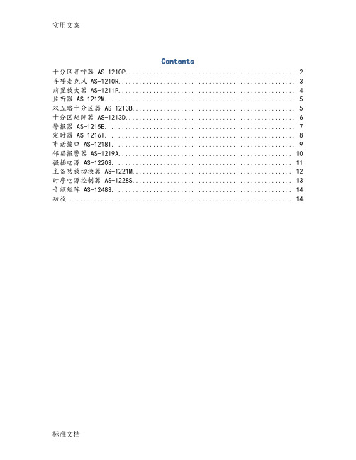
Contents十分区寻呼器 AS-1210P (2)寻呼麦克风 AS-1210R (3)前置放大器 AS-1211P (4)监听器 AS-1212M (5)双五路十分区器 AS-1213B (5)十分区矩阵器 AS-1213D (6)警报器 AS-1215E (7)定时器 AS-1216T (8)市话接口 AS-1218I (9)邻层报警器 AS-1219A (10)强插电源 AS-1220S (11)主备功放切换器 AS-1221M (12)时序电源控制器 AS-1228S (13)音频矩阵 AS-1248S (14)功放 (14)十分区寻呼器 AS-1210P性能特点(1)10分区寻呼报警功能(2)音频信号采用优质平衡传输连接技术(3)音频信号、控制信号采用双绞线同缆实时传输连接技术(4)采用专业级钟声提示音音效电路技术(5)具有四级优先权设计,分别为:本机MIC 1、钟声提示音为最高优先级,紧急音频信号(EMC)为第二级,寻呼麦克风1(MIC1)为第三级,寻呼麦克风2、3、4 (RMIC 2、3、4)和线路(AUX)为第四级(6)采用地址拨码,同时最多8台分区寻呼器相连接(7)15针电脑激活接口,低电平报警激活性能规格表寻呼麦克风 AS-1210R性能特点(1)具有8个分区寻呼器选择按键和10个分区选择键,能够对80个分区进行远程寻呼(2)具有全开,全关按键便于操作(3)具有一个鹅颈式麦克风和麦克风控制键,音频信号采用平衡传输方式,具有信号质量和传输距离(4)具有一个输出口,传输线采用屏蔽双绞线,同时传输音频信号的控制信号,方便安装性能规格表前置放大器AS-1211P功能描述:(1)多种、多个输入/输出口:5个话筒输入口;3个线路输入口;2个紧急输入口;4个输出口。
(2)各通道独立音量控制(3)高音和低音音调控制(4)自动默音(0-30dB)(5)紧急输入无音量控制性能规格表监听器 AS-1212M功能描述:(1)10个通道供任意选通(2)5个单元LED电平指示(3)监听音量可调(4)内置监听扬声器性能规格表双五路十分区器 AS-1213B功能描述:(1)2路输入(A和B),10通道输出,每路功率输入负载5个区域(2)10个通道分区可以任意选取通.十分区矩阵器 AS-1213D功能描述(1)2路输入(A和B),10通道输出,有强行插入功能切换通道功率音频信号(2)15针紧急警报激活口,10路报警信号输入,低电平报警激活.(3)当有警报信号输入时,相应通道自动切换到通道B,并且输出两路短路激活报警信号.警报器 AS-1215E功能描述(1)自动触发报警,输出消除报警声或预先固化的语音信号(2)60秒钟数字录/放语音IC,可擦可写(3)录/放电平可控定时器 AS-1216T功能描述(1)AP-9816T是一款功能强大的电源定时控制器,采用中文液晶显示,可定时控制五路电源输出,1路短路定时输出;(2)可以设置节假日,使定时操作非常灵活,单键飞梭的使用操作更加方便快捷,可以帮你实现各种定时电源控制功能.性能规格表市话接口 AS-1218I性能特点(1)本机是公共广播系统的配套设备,可将市话转换入广播系统,具有电话线路输入,音频输出接口。
AS系列电动执行机构说明书
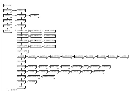
同F1
同F1
继电器S4百分数设置
P4
同F1
同F1
继电器SS功能设置
SF
同F1、功能PO无效
同F1、功能PO无效
ESD使能设置
A1
OF、ON
无效、使能
ESD方向设置
A2
SP、CL、OP
停止、关闭、打开
ESD控制形式
A3
NO、NC
高电平有效,低电平有效
ESD温度保护旁路
A4
OF、ON
无效、使能
ESD联锁控制旁路过
继电器S5功能设置
F5
同F1
同F1
继电器S5百分数设置
P5
1-99
同P1
继电器S6模式设置
S6
NO、NC
同S1
继电器S6功能设置
F6
同F1
同F1
继电器S6百分数设置
P6
1-99Βιβλιοθήκη 同P1继电器S7模式设置S7
NO、NC
同S1
继电器S7功能设置
F7
同F1
同F1
继电器S7百分数设置
P7
1-99
同P1
继电器S8模式设置
初始设置2
D2
设定执行器全行程25圈,当前阀位50%
帮助菜单
H*
具体含义见后
A5
OF、ON
无效、使能
ESD就地停止旁路
A6
OF、ON
无效、使能
自维持设置
A7
OF、ON
无效、使能
开关优先设置
A8
SP、CL、OP
停止、关优先、开优先
联锁控制
A9
OF、ON
无效、使能
双燃料发动机参数调试
第1节 ESD5335控制器调试
1
第1节 ESD5335控制器调试 版面英文翻译: 版面英文翻译:
ACTUATOR 执行器 BATTERY 电瓶 PICK-UP 转速传感器 GROUND 接地 STARTING FUEL 起动燃油量 FUEL RAMP 起动加速度 SPEED RAMP 速度斜坡
第7节 调节发动机
调节DIESEL LIMIT(燃油限制),将额定 负荷的燃油替代率调到80%以上,用万用 表测量并记录好25%,50%,75%,90% ,100%负荷的燃气反馈和燃油反馈。
第7节 调节发动机 控制屏在正常状态下是: 起车,机器加到额定转速,带上大约25%的负荷(带 上负荷双燃料好调一些,并非一定要带负荷)。 管道天然气全打开,天然气进入管道,(调压阀需要 手动拉下才能进气)气压开关受到气体压气闭合,开 关拧到双燃料,分流控制器得到信号,继电器2亮, 27-28常闭点被分开,进入双燃料状态。 用螺丝刀逆时针调动DIESEL LIMITS (柴油限位)旋 扭。直到GAS RELAY (燃气延时)红灯亮,此时 DFM100上31-32闭合,分流控制器得到信号,继电器 1亮,电磁阀开。
第3节 RSC671斜坡器和YD927转速模块 RSC671斜坡器和YD927转速模块
第4节 TMC2000显示模块
AF2000显示模块主要是通过CAN总线对分流控制 显示模块主要是通过 显示模块主要是通过CAN总线对分流控制 器的原始参数、通讯参数及各检测功能参数进行手动输 器的原始参数、 入设置,或过232接口与计算机连接后进行设置。它 接口与计算机连接后进行设置。 入设置,或通过232接口与计算机连接后进行设置 可以对发动机的运行进行动态监控,同时它还具有记录 可以对发动机的运行进行动态监控, 200条数据的存储功能。超过200条时 200条数据的存储功能。超过200条时,将从最早的记 条时, 条数据的存储功能 录开始刷新。所有的故障都会按照发生的日期和时间被 录开始刷新。 存储起来。并且,整个过程的所有测量值都会被记录下 存储起来。并且, 来。 给用户的正常操作和维修带来了方便。 给用户的正常操作和维修带来了方便。
菲斯特 RSP 254 255 气体压力调节器和 AS 254 255 执行器说明书

Gas pressure regulator RSP 254 / RSP 255RegulatorR 70-10 / R 70-20 / R 70-100 ActuatorAS 254 / AS 255Product informationApplication, Characteristics, Technical Data 5Application 5Characteristics 5Type of model (option) 5Technical Data 6Design and function of the gas pressure regulator (GPR) 7Design and function of the safety shut-off valve (SSV) direct-acting 7Design and function of the safety shut-off valve (SSV) indirect-acting 7Sectional view Actuator AS 255 8Sectional viewRegulators R 70-10, R 70-20, R 70-100 and SSV control device K 70-10 9K G * value 10Accuracy class AC / Closing pressure group SG 10Response pressure group AG (SSV direct-acting) 10Response pressure group AG(SSV indirect-acting) control device K 70-10 10SSV setpoint spring table - Control device direct-acting 11SSV setpoint spring table - Control device direct-acting 12Regulator setpoint spring table 12AS 254: Connection of the functional line and breather line 13AS 255: Connection of the functional line and breather lines 13R 70: Connection of the functional line and breather lines 13K 70: Connection of the functional line and breather lines 13Design 14Calculation of the required K G value 14Device selection 14Dimensions, Connection and Weight 15Dimensional drawing of gas pressure regulator 15Dimensional drawing of regulator 16Dimensional drawing of control device 16Dimensions and weight 17Installation situations 18Connection example 19Gas pressure regulator RSP 254 with integrated SSV indirect-acting 19Gas pressure regulator RSP 254 with integrated SSV indirect-acting Regulator R 70-10/2 with pneumatic 1:2 follow-up setpoint converter 20Gas pressure regulator RSP 254 with integrated SSV direct-acting Regulator R 70-100 21Order data 22Contact 23Notes 25-26Table of ContentsAC Accuracy class AG o Upper response pressure group AG u Lower response pressure group BV Breather valve HDS High-pressure screw spindle K G value p d Outlet pressure p ds Setpoint of the outlet pressure p dso Upper SSV response pressure p dsu Lower SSV response pressure PS Maximum allowable pressure p u Inlet pressure ρn Standard gas density P dF Pneumatic follow-up setpoint from I/P converter P d100 Outlet pressure R70-100P d20 Outlet pressure R70-20P d20s Outlet pressure R70-10 with 1:2 pressure converter for follow-up setpoint adjustment P d10s Outlet pressure R70-10 with 1:1 follow-up setpoint adjustment P d10 Outlet pressure R70-10Q n Standard volumetric flow rate RSD Throttle valve SSV Safety shut-off valve SD Setting device SG Closing pressure group At Actuator t ugas Gas inlet temperature VS Valve seat w u Inlet gas velocity w d Outlet gas velocity W dso Upper adjustment range (SSV)W dsu Lower adjustment range (SSV)Δp wo Min. re-engagement differencebetween upper response pressure and normal operating pressure Δp wu Min. re-engagement difference between lower response pressure and normal operating pressure MOP Maximum operating pressure in a system MOP d Maximum operating pressure upstream of the system FF micro filterList of abbreviations and formula symbols• Optionally with micro filter FF upstream of the regulator• Optionally with pneumatic follow-up setpoint from I/P converter • With built-in noise reduction • With SSV manual release• With SSV electromagnetic remote release when power is applied or in case of power failure • With electric position indicator SSV 'Closed' via inductive proximity initiator or via Reed contact • With BV breather valve (for SSV release in case of diaphragm breakage)• Coating with epoxy resin in RAL colours • Special model such as Wobbe correctionfor burner controlApplication, Characteristics, Technical DataApplicationGas pressure regulator (GDR), indirect-acting (operating with auxiliary power), for systems acc. to DVGW - work sheet G 491 (A) and G 600 (A) (TRGI)Can be used as an equipment component on gas consumption facilities as defined in EC Directive EU/2016/426 (GAR)Can be used for the gases defined in DVGW - work sheet G 260 / G 262 and neutral non-aggressive gases.(other gases on request)CharacteristicsType of model (option)• Regulator with double-diaphragm system • Model according to DIN EN 334 / 14382 • Integral pressure-tight model (IS)• Gas pressure regulator with or without integrated SSV • Compact and maintenance-friendly modular design • SSV functional class, optionally A or B to DIN EN 14382•Open-air modelP = burner pressureconstantTechnical DataGas pressure regulator RSP 254 / RSP 255 (with integrated SSV)RP 254 / RP 255 (without integrated SSV)Actuator model AS 254 / AS 255 (with integrated SSV)A 254 / A 255 (without integrated SSV)Safety shut-off valve (SSV) with MD control device (W dsu 8 mbar - 50 mbar ; W dso 50 mbar - 400 mbar)With MD-R control device (W dsu 30 mbar - 200 mbar ; W dso 300 mbar - 4,000 mbar)With K 70-10 control device indirect-acting (W dso 2,000 mbar - 12,500mbar)Regulator modelsR 70-10, R 70-20, R 70-20 (1:2), R 70-100Required pressure difference for pilot regulator 500 mbarModelIntegral pressure-tight (IS)Max. allowable pressure PS 16 bar Max. inlet pressure p u,max 16 barNominal widths RSP 254: DN 25, DN 50, DN 80, DN 100, DN 150, DN 200RSP 255: DN 50, DN 80, DN 100 Actuator flange connection DIN EN 1092 - flanges PN 16ASME - B16.5 - flanges Class 150 RFPipe connection type G 1/4“ or G 3/8“ for threaded pipe connections toDIN EN ISO 8434-1 (DIN 2353)Actuator material Al cast alloy Regulator materialAl wrought alloyTemperature range-20 °C to +60 °C to DIN EN 334/ 14382(Operating/ambient temperature)Function, Strength and Tightness DIN EN 334 / 14382Corrosivity category* DIN EN ISO 12944-2Ex protection The mechanical components of the device do not have any ignition sources of their own and are thus not covered by the scope of ATEX (2014/34/EU).Electrical components used at the device fulfil the ATEX requirements.*) Categories C1 to C5-I are guaranteed without additional coatings. For category C5-M, an epoxy resin coating is recommended.Application, Characteristics, Technical DataDesign and function of the gas pressure regulator (GPR)The gas pressure regulators RSP 254/255 have the function of keeping the outlet pressure of a gas train downstream of a gas pressure regulator largely constant within specified limits, independently of changes in the gas tap or inlet pressure. The required auxiliary energy is obtained from the pressure gradient between the inlet pressure and outlet pressure of the gas pressure regulator. No external energy is required, and no gas whatsoever will flow out of the system into the surrounding atmosphere in standard operation. The regulator consists of the regulating unit, optionally connected upstream to a micro filter and bypass valve.The control variable - the outlet pressure - is detected by a sensitive diaphragm in the regulating unit, which is part of a double-diaphragm system. The pneumatic amplifier working by the nozzle/baffle plate principle is actuated by the comparator formed by a double-diaphragm system. The bypass valve and possible changes in the setpoint spring can be used to affect the static amplification of the regulator and adjust it to the respective condition of a gas train.The outlet pressure is applied to the top side of the double-diaphragm system in the regulating unit via a measurement line, converted into a pressure force and compared with the set setpoint spring force as command variable. Any deviation from the control value is followed by a suitable proportional change in the spacing between nozzle and baffle plate, corresponding to a proportional change in the setting pressure. The valve opening required in each case for adjusting the outlet pressure actual value to the setpoint is effected by the setting pressure generated by the actuating drive of the actuator.In the operating state, the inlet pressure taken at the inlet flows as auxiliary energy through the nozzle/baffle plate system and the bypass valve into the outlet pressure chamber, generating, depending on the position of the nozzle/baffle plate system, the setting pressure for the valve opening position required in each case against the bypass valve. The auxiliary energy gas then flows back to the outlet pressure network via the bypass valve.In case of zero tap of the gas train, the amplifier valve in the double-diaphragm system of the regulating unit will close tight, causing the closing pressure to be established.Models with pneumatic follow-up setpoint inputs with 1:1 and 1:2 pressure conversions are available. Using, for example, IP converters allows you to continuously set directly the required outlet pressure setpoint via, for example, 4 to 20 mA signals.Moreover, by means of a setting spring, variable zero points can be suppressed.Design and function of the safety shut-off valve (SSV) direct-actingIn case of inadmissible overpressure or lack of gas in the gas train, the actuator of the safety shut-off valve arranged in the same housing on the inlet side will shut off the gas flow.To this end, the outlet pressure to be monitored is passed on to the SSV control device via a separate measurement line. As a function of the change in pressure, the SSV diaphragm in the control device is raised or lowered. When the outlet pressure in the gas train exceeds or falls below a certain response pressure, the switch socket connected to the SSV diaphragm will move to the corresponding disengaging position, the balls of the engaging mechanism will release the SSV screw spindle, and the closing spring will press the SSV valve plate against the valve seat. The SSV actuator shuts off the gas flow gas-tight. The SSV can only be opened by hand and engaged in the open position. To do so, the outlet pressure at the measuring point must be lowered below the upper response pressure or raised above the lower response pressure by at least the re-engaging differential amount (Δp). The SSV can, except where otherwise stipulated in national legislation, be used either in function class A (with diaphragm rupture protection) or B (without diaphragm rupture protection).There is also the option of using a remote display for the SSV position 'CLOSED' and a manual and remote release when power is applied or in case of power failure.Design and function of the safety shut-off valve (SSV) indirect-actingAt a safeguarding pressure of the gas train of greater than 4 bar, the SSV must be combined with a control device K70-10. In this case, the SSV switching device is designed as function class B and set to a switching pressure of approx. 500 mbar. The control device K70-10 connected upstream of the switching device is set to the upper safeguarding pressure. As soon as the pressure of the gas train reaches the upper safeguarding pressure, the control device will open and allow the gas pressure to flow to the measurement connection of the SSV switching device. Here a pressure of more than 500 mbar will build up, causing the switching device to release as described above. The excess pressure in the measurement line will be let down by flowing into the breather line via the bypass throttle and safely released into the atmosphere.Setting deviceSSVActuator housingSSV connection optionsBV breather valve Sectional viewActuator AS 255• Wdsoup to4 bar with controldevice MD or MD-R• Wdsofrom 4 bar with controldevice K 70-10 (indirect-acting)Option: Noise reductioncontrol deviceInlet pressureSetting pressureOutlet pressureAtmosphereNoise reductionFF micro filter for R70FF micro filterSectional viewRegulators R 70-10, R 70-20, R 70-100 and SSV control device K 70-10R 70-10R 70-20R 70-100Double-diaphragm systemDouble-diaphragm systemSetpoint spring 100 cm 2Measuring movementSetpoint springBypass setting deviceR 70-20with pneumatic 1:2 pressure converter for follow-up setpoint adjustment, for example, via I/P converterBypass setting device 20 cm 2Measuring movementDouble-diaphragm systemSetpoint spring Double-diaphragm system10 cm 2Measuring movementI/P converter Pressure converter20 cm²K 70-10SSV control deviceSetpoint setting deviceSetpoint setting deviceSetpoint setting deviceBypass setting deviceApplication, Characteristics, Technical DataK G * valueAccuracy class AC / Closing pressure group SG*) KG value for natural gas: d = 0.64 (ρn = 0.83 kg/m³), t ugas = 15 °C **)Optionally, the control device K70-10 can be used as SBV.(Δp u,max ± 2bar )Setting device is approved for a max. pressure differential of 0.5 barUpper response pressure group AG30 mbar to 100 mbar AG 10100 mbar to 500 mbar AG 5> 500mbar AG 2.5Lower response pressure AG5 mbar to 30 mbar AG 2030 mbar to 50 mbar AG 10> 50mbar AG 5Response pressure group AG (SSV direct-acting)Upper response pressure group AG800 mbar to 4,000 mbar AG 2.5> 4,000 mbar AG 2,5Response pressure group AG(SSV indirect-acting) control device K 70-10**Determining the upper response pressureOutput pressure P dUpper response pressure W dso *≤200 mbarP d +100 mbar >200 mbar to ≤800 mbar P d x 1.5>800 mbar to ≤1600 mbarP d x 1.3> 1600mbarP d +500 mbarP h Pneumatic follow-up setpoint from I/P converter (0-6 bar)P d100 Outlet pressure R70-100 P d20 Outlet pressure R70-20 P d 20s Outlet pressure R70-10 with follow-up setpoint 1:2P d10 Outlet pressure R70-10 P d 10s Outlet pressure R70-10 with follow-up setpoint 1:1P dOutlet pressure K70-10*) The upper response pressure is rounded up to full tens, for example 251 mbar-> 260 mbarRegulator setpoint spring tableDimensions, Connection and WeightAS 254: Connection of the functional line and breather lineNominal widthSetting deviceSSV control device direct-actingSetting pressure line / Return lineSSV measurement lineBreather lineDN 025Connection* for: Tube 12 x 1.5 (thread G 3/8)Connection* for: tube 12 x 1.5 (thread G 1/4)DN 050DN 080DN 100DN 150Connection* for: tube 12 x 1.5 (thread G 3/8)DN 200AS 255: Connection of the functional line and breather linesNominal widthSetting deviceSSV control device direct-actingSetting pressure line / Return lineSSV measurement lineBreather lineDN 050Connection* for: Tube 12 x 1.5 (thread G 3/8)Connection* for: tube 12 x 1.5 (thread G 1/4)DN 080DN 100Connection* for: tube 12 x 1.5 (thread G 3/8)*) Threaded pipe connections to DIN EN ISO 8434-1 (DIN 2353)Note: Observe the following documents in relation to installation, start-up and maintenance:DVGW - work sheets G 491 and G 600Operating and Maintenance Instructions RSP 254 / 255The gas pressure regulators RSP 254 / 255 shall be installed in the pipeline preferably in horizontal position. For all nominal widths, the direction of flow is indicated by an arrow on the housing.Function / Breather lineR 70-10Connection* for: Tube 12 x 1.5 (thread G 1/4)R 70-20 (1:2)R 70-100R 70: Connection of the functional line and breather linesFunction / Breather lineK 70-10Connection* for: Tube 12 x 1.5 (thread G 1/4)K 70: Connection of the functional line and breather linesDesignCalculation of the required K G valuep d / p u > 0.5K G value ata sub-critical pressure ratioK G = Q n / √p d ⋅(p u -p d )p d / p u ≤ 0.5K G value ata super-critical pressure ratioK G = 2∙Q n / p uNote: all calculated pressures are absolute pressures.Device selectionThe device is selected on the basis of its K G value from the table of flow rate coefficients (page 10)Note: For the device design, a capacity reserve of 10% is recommended.Example:p u min 5.0 bar / p u max 8.0 bar p d min 0.3 bar / p d max 0.5 bar Q n min 800 m³/h/Q n max 1500 m³/h1.5 bar / 6 bar = 0.25 < 0.5à Supercritical pressure ratio K G = 2∙1500 / 6 = 500 ((m³/h)/bar)AS 254 DN 50 VS 32.5 K G value: 750 (m³/h)/barB SELDimensional drawing of gas pressure regulatorADimensions, Connection and WeightL1SESELLAAL1L1B BA 1A 1A 1L2L2L2Gas pressure regulator RSP 255 consisting of:Actuator AS 255Regulator R 70-10 Control device K 70-10Gas pressure regulator RSP 255 consisting of:Actuator AS 255Regulator R 70-20/2 with I/P converterControl device K 70-10Gas pressure regulator RSP 255 consisting of:Actuator AS 255Regulator R 70-100Control device MD or MD-RI / P converter not includedDimensional drawing of regulatorR 70-10R 70-20R 70-100CDECDEECPressure range: 0.5 bar - 12 barPressure range: 0.1 bar - 6 barPressure range: 10 mbar - 500 mbarDimensional drawing of control deviceK 70-10CDER 70-20/2 with follow setpoint adjustment (1:2)Pressure range: 2 bar - 12,5 barGas pressure regulator RSP 254RSP 255 Nominalwidth Dimensions DN25DN50DN80DN100DN150DN200DN50DN80DN100A [mm]RE 320214232-------RE 385/390--293308370510292370441A1* [mm]R 70-10345365423438500640422500571 R 70-20R 70-100B [mm]270282305315386400305311386 L [mm]230230310350480600310410480 L1* [mm]500500585616598800586660710L2* [mm]R 70-10480480502514462570501520542 R 70-20R 70-100Y [mm]100100100100150150100150150Weight [kg]RE 32013.515----22--RE 385/390--28295888-4258Actuator connectionDIN EN 1092 - PN16 ASME B 16.5 - Class 150Regulator R 70-10R 70-20R 70-100C [mm]9494Ø161D [mm]124124124E [mm]227.5259283.5Weight [kg] 3.7 4.2 5.3 Regulator connection G 1/4Control device K 70-10C [mm]70D [mm]124E [mm]250Weight [kg] 3.7Control device connection G 1/4Reactivation of SSVYDimensions and weight*) The dimensions given are …max.“ and depending on the control device and piping!Installation situationsRSP 255 shown with actuator AS 255incl. switching device MD or MD-R,Regulator R 70-10 and control device K 70-10RSP 255 shown with actuator AS 255 incl. switchingdevice MD or MD-R, regulator R 70-20/2,I/P converter and control device K 70-10RSP 255 shown with actuator AS 255 incl. controldevice MD or MD-R and regulator R 70-100Connection R70 / K70Connection exampleGas pressure regulator RSP 254with integrated SSV indirect-actingInlet pressure lineBypass lineReturn lineSetting pressure lineClosing springSetpoint springActuatordiaphragmEqualizationdiaphragmValve plateSSV switching deviceActuator AS 254Double-diaphragm systemInlet pressureSet pressureOutlet pressureAtmosphereRegulator R 70-10SSVBreatherlineSetpoint springWdsogreater than 4 bar withcontrol device K 70-10Setpoint setting deviceBypass settingdeviceFlow restrictorSSV switching pressureBypass throttle*SetpointsettingdeviceFlow restrictorDouble-diaphragm system*) permanently installed bypass valve (baffle plate) Ø 1mm234115 1Inlet pressure lineBypass lineReturn lineSetting pressure lineClosing springSetpoint springEqualizationdiaphragmValve plateSSV switching deviceI/P converter1:2 pressure converterCompressed air supply Double-diaphragm systemInlet pressureSetting pressureOutlet pressureAtmosphereFollow-up setpoint1:2 follow-up setpoint converterSSVGas pressure regulator RSP 254with integrated SSV indirect-actingBypass settingdeviceSetpoint setting deviceSSV switching pressureFlow restrictorBypass throttle*B re a t h e rlineControl device K 70-10SetpointsettingdeviceFlow restrictor4-20 mADouble-diaphragm systemSetpoint springActuator AS 254*) permanently installed bypass valve (baffle plate) Ø 1mmActuatordiaphragm23115141236Inlet pressure lineBypass lineReturn lineSetting pressure lineClosing spring Setpoint springActuatordiaphragmEqualizationdiaphragmValve plateSSV measurement lineBreather valveSSV control device100 cm2 measuring movementDouble-diaphragm systemMeasurement lineRegulator R 70-100SSVInlet pressureSet pressureOutlet pressureAtmosphereGas pressure regulator RSP 254with integrated SSV direct-actingBypass settingdeviceSetpointsettingdevice Actuator AS 254Order dataExample:Actuator withgas pressure RSP 254/050/390/32,5/MD-R/left/SR/BV/N/H/R 70-10/WAZ/So ArrayIn each selection group, Array only one option can be selectedin each case.*) for example coating withepoxy resin in RAL coloursMEDENuSGas-Druckregeltechnik GmbHSaßmicker Hammer 40 D-57462 Olpe Phone: +49 (0)2761 82788-0Fax: +49 (0)2761 82788-9E-M a il:***************Internet: www.medenus.deIf you want to know more about our products and services, please contact your local representative or visit our website at www.medenus.de/en.In-House Sales Maike SchmidtT elephone: +49 (0) 2761 / 82788-11Fax: +49 (0) 2761 / 82788-9E-M a il:********************In-House Sales Jan ArensT elephone: +49 (0) 2761 / 82788-20Fax: +49 (0) 2761 / 82788-9E-M a il: j.a ***************Worldwide Sales Agencies:medenus.de/en/kontakt.htmlManaging Director Alexander ChristianiT elephone: +49 (0) 2761 / 82788-18Field Sales GermanyJörg PflugnerMobile: +49 (0) 170 635 5309Fax: +49 (0) 2761 / 82788-9E-Mail: *********************ContactIn-House Sales Stefanie MüllerT elephone: +49 (0) 2761 / 82788-13Fax: +49 (0) 2761 / 82788-9E-M ail:********************THE MEDENuS PLuS10 reasons for good business relations1. Consultancy expertise and quality standards developed over decades2. Broad and proven standard range of feedback controllers3. Modern, fast and efficient production for series products and for individual orders4. Customer-specific design of pressure regulators and vacuum regulators and special designs5. Guaranteed deadline compliance with a delivery deadline guarantee6. Fast response time in all matters7. Sufficiently large parts storage for production and spare parts8. Customer-specific theory & practice training courses9. Modular design right across the entire product range to facilitate optimized handling of spareparts10. 100% Made in GermanyNotes .............................................................................. .............................................................................. .............................................................................. .............................................................................. .............................................................................. .............................................................................. .............................................................................. .............................................................................. .............................................................................. .............................................................................. .............................................................................. .............................................................................. .............................................................................. .............................................................................. .............................................................................. .............................................................................. .............................................................................. .............................................................................. .............................................................................. .............................................................................. .............................................................................. .............................................................................. .............................................................................. ..............................................................................German:http://medenus.de/files/upload/downloads/RSP 254/Pi_RSP 254_255_de.pdfEnglish:http://medenus.de/files/upload/downloads/RSP 254/Pi_RSP 254_255_en.pdfIn the download area of our homepage, this document is available in different languages. You can use the following QR codes and links to go directly to this document in your language.MEDENuS Gas-Druckregeltechnik GmbH Fon +49 (0)2761 82788-0Fax +49 (0)2761 82788-9Saßmicker Hammer 40 / D-57462 Olpe ***************www.medenus.de。
可编程控制器ASI总线

表
通信协议各层的主要功能
.传输物理层
图 传输物理层模块图
.传输控制层
图 报文传输周期
图 传输控制层的工作过程
.执行控制层 .主机接口层
主站模板
接口网络是工厂自动化系统的最底 层网络。使用规范的两芯黄色电缆连接 大量的传感器执行器。它采用绝缘穿刺 技术,组装起来方便高效。
网络由主站、从站和从站供电单元 组成。在有中继器时电缆长度可以达到, 每个中继器产生的网段必须有自己单独 的电源模块。
总线的技术特点如下。 ()完整的总线系统 ()应用十分简便 ()传输快 ()功能可靠 ()节省资金 ()系统开放
系统组成
总线系统由主站、从站和传输系统 三部分组成。而传输系统又由两芯传输 电缆、电源和数据解耦电路构成。
现场总线是由网关、输入模块、输 出模块和扁平电缆组成。
其中,网关是传感器、执行器层和 上层不同现场总线系统的连接点,可使 和上层不同现场总线进行数据交换,上 层总线可以包括、、、、、,其方式如 图所示。
第章 总线
重点与难点
系统组成、通信原理、主站模板、 西门子网关 。
基本要求
.熟悉系统组成和通信原理; .掌握主站模板和网关 ;
本章内容
.总线概述;
.系统组成;
.通信原理;
.主站模板;
.网关 。
7.1
概述
7.2
- 1、下载文档前请自行甄别文档内容的完整性,平台不提供额外的编辑、内容补充、找答案等附加服务。
- 2、"仅部分预览"的文档,不可在线预览部分如存在完整性等问题,可反馈申请退款(可完整预览的文档不适用该条件!)。
- 3、如文档侵犯您的权益,请联系客服反馈,我们会尽快为您处理(人工客服工作时间:9:00-18:30)。
AS全智能化电动阀门执行器技术特点
1、电气要求
1)电动阀门执行器的电源为额定电压220V或380V、单相或三相交流电、额定频率
50Hz。
2)执行器工作的环境温度为-30︒C~+70︒C,并能耐受强电磁干扰。
3)电动阀门执行器或其减速装置的最大输出扭矩不低于对应阀门需要的最大开启和关
闭力矩,并至少有20%的富裕量。
4)执行器具有自动识别三相电源相序的功能,即无论三相电源接线顺序如何,如果接
收到“开”命令,执行器总是按“开方向”运行,如果接收到“关”命令,执行器总是按“关方向”运行,用户接线就非常方便,不会造成接线错误导致损坏执行器和阀门。
5)电动阀门执行器具备“电动/手动”切换机构,当切换到手动操作时,放开切换杆,
切换杆应能自动弹回原始位置,这时,如果执行器电动机转动,执行器能够自动置于电动操作状态。
6)用于开关型的执行器的最大启动频率不小于60次/小时,用于调节型的执行器的最
大启动频率不小于900次/小时。
2、控制功能
1)对阀门的阀位和扭矩的检测和控制是采用电子方式,不同于普通电动执行器采用的
行程开关等纯机械式检测和控制方式。
这样,有效保证了对阀门的阀位和扭矩参数进行稳定、精确的测量,有效的保证了用户使用的可靠性。
电动执行器对阀门阀位的检测精度< 0.2%,对阀门扭矩的检测精度< 5% 。
2)执行器带有全中文菜单的运行和设置液晶显示界面,用户可通过红外线设定器对执
行器的参数在现场根据需要进行设置,操作非常简单和便捷。
3)电动阀门执行器能够将当前的输出扭矩和阀位通过自带的液晶显示屏实时显示出
来,操作人员在现场就可方便监控。
当阀位到达预定位置或输出扭矩超过预先设定的值,执行器能够自动停转,并进入待命状态。
4)阀门的全开和全关位置,以及最大保护扭矩,能够在现场通过红外线设定器由用户
自行设置,执行器能够存储这些设置,并按这些设置来运行。
5)执行器具有故障保护功能,包括电源缺相保护、电机过热保护、阀门卡塞保护、瞬
时逆转保护、电机过流保护等,出现这些故障后,执行器能够自动发出报警,并能自动停转。
6)执行器支持总线控制方式,支持Modbus RTU或Profibus DP等通用协议,也支持多
线控制方式。
(由用户要求配置,标准配置中不含总线控制功能板卡)
7)执行器的输出扭矩值和阀位值能够通过4-20mA信号输出,以便中央控制系统采集
和处理。
用于调节型的执行器能够接收4-20mA控制信号,按该信号实时控制阀位。
(由用户要求配置,标准配置中不含模拟量控制功能板卡)
8)电动执行机构在失去动力电源时,应能保持在失电前的原位保持不动,在失去控制
信号时,可根据用户设定选择开、关、停在原位不同的应急措施。
3、密封和防护
1)执行器的防护等级应达到IP68。
能适应于各种潮湿、多尘现场恶劣环境。
2)执行器的现场接线端子采用双密封结构,在打开端子室盖接线时,周围的潮湿型气
体、粉尘、爆炸型气体不会侵入到执行器内部,有效保障执行器的可靠运行。
3)执行器现场操作旋钮或按钮的轴采用非贯穿执行器外壳方式,以免影响防水。
4)执行器应采用液态油润滑,无论何种安装方位,均不出现润滑油渗漏的现象。
4、质量保证
执行器的保质期为1年,在保质期内由于非人为因素造成的故障,均由厂家免费维护。
执行器性能参数表。
