NI VeriStand 使用手册(概述 建模 创建MiL环境)
[NI技术]使用NI VeriStand 实现汽车ECU的 HIL测试
![[NI技术]使用NI VeriStand 实现汽车ECU的 HIL测试](https://img.taocdn.com/s3/m/2417bb37376baf1ffc4fadee.png)
[NI技术]使用NI VeriStand 实现汽车ECU的 HIL测试"NI VeriStand 与NI PXI平台的结合满足了用户对 I/O、计算能力、信号仿真和数据分析等功能的需求,而且是完全开放和模块化的。
"- Enrico Corti,The Challenge:基于商业现成 (COTS)的硬件,为发动机和整车的实时仿真开发一个模块化的硬件在环 (HIL)测试系统,以减少嵌入式软件验证过程中所需的测试次数。
The Solution:基于NI VeriStand 实时测试软件和 NI PXI硬件的测试系统提供了用户所要求的计算能力,可以利用现场可编程门阵列(FPGA) 硬件实现高速控制,同时,各种不同的 I/O不仅能保证该 HIL系统可以满足当前的需求,而且可进行功能扩展以满足未来的应用需求。
HIL系统集成Author (s):Enrico Corti -是一家总部设在意大利北部的公司,为汽车的校准、控制和测试提供定制的解决方案。
根据客户的需求,提供纯软件(模型或基于模型的分析),或集成硬件和软件的解决方案。
Eldor 公司提供汽车电子组件,如线圈、离子感应系统和电子控制单元(ECU)。
因为HIL系统可以用来实现自动化和标准化测试,所以它们是ECU测试的标准。
大多数市场上可用的HIL系统提供的是不能扩展或定制的标准功能, Eldor公司选择了由Alma汽车公司提出的HIL解决方案,因为该方案的硬件和软件是开放的,并可以完全根据他们的需求定制。
HIL系统必须仿真由ECU控制的设备,所有进入ECU 的实际信号必须由 HIL测试系统产生的信号代替。
因为目标是测试ECU的功能,所以仿真必须实时运行。
模型必须精确地对ECU命令进行响应,以测试整个嵌入式控制系统。
对于某些类型的信号,复现一个正确的时基是很困难的,因为高频率的信号需要与曲轴的瞬时位置同步。
这种典型的例子包括缸内压力、加速度计、离子电流和进气压力信号。
在NI VeriStand中如何创建第三方设备
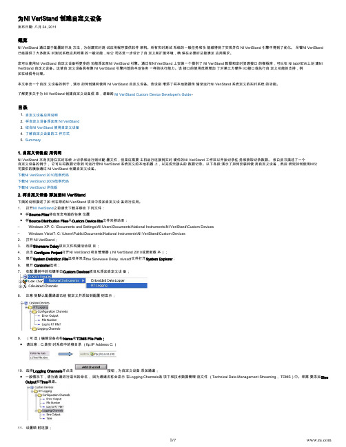
1. 2. 3. 4. 5. 为NI VeriStand 创建自定义设备发布日期: 八月 24, 2011概览NI VeriStand 通过基于配置的开发 方法,为创建实时测 试应用程序提供软件 架构。
所有实时测试 系统的一般任务和功 能都得到了实现并在 NI VeriStand 引擎中得到了优化。
尽管NI VeriStand 已经提供了大多数实 时测试系统应用所需 的一般功能,NI公 司还进一步设计了自 定义和扩展环境,确 保在必要时总能满足 应用需求。
您可以使用NI VeriStand 自定义设备将更多的 功能添加至NI VeriStand 引擎。
通过在NI VeriStand 上安装一个提供了 NI VeriStand 数据和定时资源接口 的模板库,可以在 NI labVIEW上创 建NI VeriStand 自定义设备。
这使自 定义设备具有像 NI VeriStand 引擎内部的本地任务 一样的执行能力。
该 接口的使用范例增加 了对第三方硬件 I/O接口或执行自 定义功能的支持,例如在线信号处理。
本文举出一个自定 义设备的例子,演示 如何创建和使用 NI VeriStand 自定义设备。
该设别 增添了将本地数据传 输至运行NI VeriStand 系统定义的实时系统 的功能。
了解更多关于为 NI VeriStand 创建自定义设备信 息,请查阅。
NI VeriStand Custom Device Developer's Guide 目录自定义设备应用说明将自定义设备添加至 NI VeriStand结合NI VeriStand 使用自定义设备了解自定义设备的工 作方式Summary1. 自定义设备应 用说明NI VeriStand 本身支持在实时系统 上记录和运行测试配 置文件,但是这需要 主机运行连接到实时 硬件的NI VeriStand 工作区以开始记录任 务和获取记录数据。
NI VeriStand 使用手册(概述 建模 创建MiL环境)
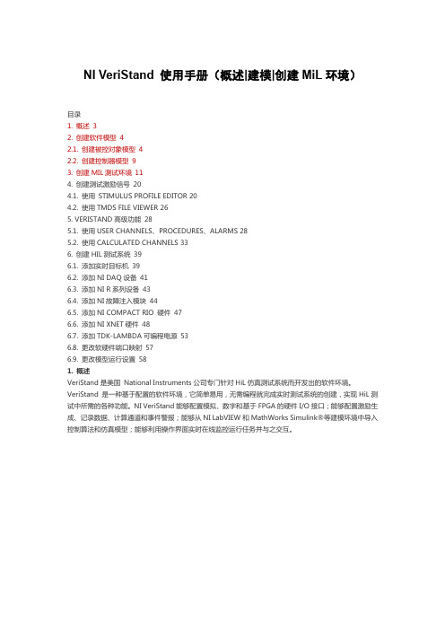
NI VeriStand 使用手册(概述|建模|创建MiL环境)目录1. 概述32. 创建软件模型42.1. 创建被控对象模型42.2. 创建控制器模型93. 创建MIL测试环境114. 创建测试激励信号204.1. 使用STIMULUS PROFILE EDITOR 204.2. 使用TMDS FILE VIEWER 265. VERISTAND高级功能285.1. 使用USER CHANNELS、PROCEDURES、ALARMS 285.2. 使用CALCULATED CHANNELS 336. 创建HIL测试系统396.1. 添加实时目标机396.2. 添加NI DAQ设备416.3. 添加NI R系列设备436.4. 添加NI故障注入模块446.5. 添加NI COMPACT RIO 硬件476.6. 添加NI XNET硬件486.7. 添加TDK-LAMBDA可编程电源536.8. 更改软硬件端口映射576.9. 更改模型运行设置581. 概述VeriStand是美国National Instruments公司专门针对HiL仿真测试系统而开发出的软件环境。
VeriStand 是一种基于配置的软件环境,它简单易用,无需编程就完成实时测试系统的创建,实现HiL测试中所需的各种功能。
NI VeriStand能够配置模拟、数字和基于FPGA的硬件I/O接口;能够配置激励生成、记录数据、计算通道和事件警报;能够从NI LabVIEW和MathWorks Simulink®等建模环境中导入控制算法和仿真模型;能够利用操作界面实时在线监控运行任务并与之交互。
本文介绍了NI Veristand 各项主要功能的使用方法,并按照通用的开发测试顺序编写,主要内容包括:@创建软件模型;@创建MiL测试系统;@实现自动化测试、记录数据;@创建HiL测试系统。
2. 创建软件模型NI VeriStand可以利用*.dll文件导入由Matlab/Simulink/Stateflow创建的算法或仿真模型,下图所示为Simulink模型导入NI VeriStand的过程:注意:NI VeriStand 支持的编译器包括Microsoft Visual C++ 6.0, .NET 2003, 2005 (Professional or Express), or 2008 (Professional or Express).在本章中具体介绍了上述过程的操作步骤,将一个在Matlab/Simulink环境下创建的*.mdl文件转换为NI VeriStand所支持的*.dll文件。
NI.VeriStand.v2015 1DVD实时测试应用程序

Intergraph SmartPlant P&ID 2009 SP5-ISO\
LightTools.v7.3ห้องสมุดไป่ตู้
Novas nLint 2013.09 Llinux64\
Sante DICOM Editor(dicom查看器) V3.1.24.1700\
Verdi3 2012.10 Linux32_64\
3D-SHAPE.3DViewer.v1.50\
Accelrys_Materials_Studio_v7.0\
Agilent.Antenna.Modeling.Design.System.v2007.06\
AutoDeblur.and.AutoVisualize.Gold.v9.3.4\
Cadence.CONFRML.v13.10.100.Linux\
Talren4 v2.03 1CD\
FTI FastBlank 2014 for ProE WildFire 5 - Creo v3.0 Win32_64 2CD
ITI.TranscenData.CADfix.v10.0.Win32-ISO 1CD
THE.Foundry.Colorway.v1.2V1.MacOSX 1CD
实时激励生成
计算通道
事件预警和预警响应程序
■□■□■□■□■□■□■□■□■□■□■□■□■□■□■□■□■□■□
+ 诚信合作,保证质量!!!长期有效:
+ 电.话TEL:18980583122 客 服 Q.Q:1140988741
ESKO包装立体效果绿色版AI插件(studio、deskpack) 1CD
[NI技术]使用NI VeriStand 实现汽车ECU的 HIL测试
![[NI技术]使用NI VeriStand 实现汽车ECU的 HIL测试](https://img.taocdn.com/s3/m/2417bb37376baf1ffc4fadee.png)
[NI技术]使用NI VeriStand 实现汽车ECU的 HIL测试"NI VeriStand 与NI PXI平台的结合满足了用户对 I/O、计算能力、信号仿真和数据分析等功能的需求,而且是完全开放和模块化的。
"- Enrico Corti,The Challenge:基于商业现成 (COTS)的硬件,为发动机和整车的实时仿真开发一个模块化的硬件在环 (HIL)测试系统,以减少嵌入式软件验证过程中所需的测试次数。
The Solution:基于NI VeriStand 实时测试软件和 NI PXI硬件的测试系统提供了用户所要求的计算能力,可以利用现场可编程门阵列(FPGA) 硬件实现高速控制,同时,各种不同的 I/O不仅能保证该 HIL系统可以满足当前的需求,而且可进行功能扩展以满足未来的应用需求。
HIL系统集成Author (s):Enrico Corti -是一家总部设在意大利北部的公司,为汽车的校准、控制和测试提供定制的解决方案。
根据客户的需求,提供纯软件(模型或基于模型的分析),或集成硬件和软件的解决方案。
Eldor 公司提供汽车电子组件,如线圈、离子感应系统和电子控制单元(ECU)。
因为HIL系统可以用来实现自动化和标准化测试,所以它们是ECU测试的标准。
大多数市场上可用的HIL系统提供的是不能扩展或定制的标准功能, Eldor公司选择了由Alma汽车公司提出的HIL解决方案,因为该方案的硬件和软件是开放的,并可以完全根据他们的需求定制。
HIL系统必须仿真由ECU控制的设备,所有进入ECU 的实际信号必须由 HIL测试系统产生的信号代替。
因为目标是测试ECU的功能,所以仿真必须实时运行。
模型必须精确地对ECU命令进行响应,以测试整个嵌入式控制系统。
对于某些类型的信号,复现一个正确的时基是很困难的,因为高频率的信号需要与曲轴的瞬时位置同步。
这种典型的例子包括缸内压力、加速度计、离子电流和进气压力信号。
NI TestStand 测试管理软件的概述说明书

StatementLaMessagePopupLists steps in the sequence and step group for the sequence file you select in the list bar.E x e c u t i o n V i e wDisplays the threads, call stack, and steps for the execution you select.R e p o r t V i e wDisplays the report for the execution you select.Displayssequences and other items in a sequence file.Templates List Organizes custom sequences, steps, and variables you can use as templates for building sequence files.Step Settings Pane Specifies the settings for the step, such as code module parameters, switching, flow control, and post actions.Analysis Results Pane Displays the analysis results for the current TestStand Sequence Analyzer project and for each sequence file and workspace file you analyze.Workspace PaneManages projects for source code control (SCC) integration and deployment. TestStand integrates with third-party SCC packages to add files, obtain the latest versions of files, and check files in and out. Use TestStand project (.tpj ) files to organize sequence files and code module files in folders.Sequence Hierarchy WindowDisplays a graph of the sequence call and callback relationships among sequence files and sequences to more easily visualize, navigate, and maintain test sequences.Variables Pane Displays globals, variables, parameters, and properties, including the values, that steps canaccess at run time.Displays the threads, call stack, and steps an execution runs. When execution completes, displays the report for the execution.Watch View Pane Monitors the values of specified variables, properties, and expressions during an execution.Threads PaneContains a list of threads in the current execution.Output Pane Displays output messages thatexpressions and code modules post to the TestStand Engine.Call Stack PaneDisplays the nested sequence invocations for the thread you select.Types WindowContains definitions of custom datatypes and step types all sequence files User Manager WindowAdministers users for the test station, groups to which users belong, login names, passwords, and privileges.Documentation OverviewGuide to TestStand Documentation topic in the NI TestStand Help contains links to all the TestStand documentation in electronic format and recommends the order in which you examine the documentation. Select Start»All Programs»National Instruments»TestStand» Documentation»NI TestStand Help or select Help»NI TestStand Help in the sequence editor to launch the NI TestStand Help NI TestStand Release NotesUse this document to learn about system requirements, installationinstructions, information about new features, and other changes since the Getting Started with TestStandUse this manual to familiarize yourself with the TestStand environment and the basic features you use to build and run test ing LabVIEW and LabWindows/CVI with TestStandUse this manual to learn how to use LabVIEW and LabWindows/CVI NI TestStand System and Architecture Overview CardUse this card to learn about the overall architecture of TestStand and as a reference for key TestStand concepts.NI TestStand User Interface Controls Reference PosterUse this poster as a reference of the properties, methods, and events found in the TestStand UI Controls API, as well as an illustration of the built-in connections between the TestStand UI Controls.NI TestStand API Reference PosterUse this poster as a reference of the properties, methods, and events found in the TestStand API, as well as an illustration of API inheritance.Configure the settings for deploying a test system, including the components to install and the installer settings.。
如何使用你的NI Veristand model framework
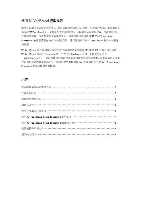
使用NI VeriStand模型框架模型是现实世界系统的数学表示。
模型通过模仿模型化系统的行为方式产生输出来对刺激做出反应NI VeriStand是一个基于配置的测试软件,可以用来运行模型仿真,探测模型信号,设置模型参数,或者与您的仿真模型交互。
本指南描述如何使用NI VeriStand Model Framework编译您的现有的C/C++模型代码,这样您就可以在NI VeriStand软件中加载您的模型。
NI VeriStand通过调用各种方法加载已编译的模型或模型dll模型DLL中的入口点函数。
NI VeriStand Model Framework是一个C文件(codegen.c)和一个相关的头文件(NIVERISTAND_API.h)您可以使用它将这些函数添加到您创建的模型中。
本指南描述了框架代码如何与您的模型代码交互,如何配置您的模型代码,以及如何使用NI VeriStand Model Framework来编译模型您的模型。
内容交互的框架代码和模型代码 (2)管理执行时间 (2)配置您的模型代码 (3)创建头文件 (3)使用符号来访问参数值 (3)使用NI VeriStand Model Framework类型定义 (4)使用NI VeriStand Model Framework编译您的模型 (5)安装模板和示例文件 (5)相关的文档 (5)框架代码和模型代码的交互使用NI VeriStand Model Framework编译您的模型之后,您可以在niveristand中运行编译好的模型DLL。
NI VeriStand在确定性时间循环中加载NI VeriStand Model Framework中的函数。
然后,您模型代码中的函数转换用户定义的数据类型,初始化您模型,并获取一个时间步长。
在NI VeriStand中,时间步长是所有任务必须完成的最小时间单位。
下图显示了NI VeriStand,模型框架代码以及您模型中的代码在一个时间步长中如何进行交互。
Multisim_10快速入门指南
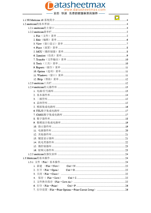
1.1 NI Multisim 10系统简介1.2 multisim的基本界面 (4)1.2.1 multisim的主窗口 (4)1.2.2 multisim菜单栏 (5)1. File(文件)菜单 (5)2. Edit(编辑)菜单 (6)3. View(窗口显示)菜单 (7)4. Place(放置)菜单 (8)5. MCU(微控制器)菜单 (8)6. Simulate(仿真)菜单 (9)7. Transfer(文件输出)菜单 (10)8. Tools(工具)菜单 (10)9. Reports(报告)菜单 (11)10. Option(选项)菜单 (11)11. Windows(窗口)菜单 (11)12. Help(帮助)菜单 (12)1.2.3 multisim工具栏 (12)1.2.4 multisim的元器件库 (13)1. 电源/信号源库 (13)2. 基本器件库 (14)3. 二极管库 (15)4. 晶体管库 (15)5. 模拟集成电路库 (16)6. TTL数字集成电路库 (17)7. CMOS数字集成电路库 (17)8. 数字器件库 (18)9. 数模混合集成电路库 (19)10. 指示器件库 (19)11. 电源器件库 (20)12. 其他器件库 (21)13. 键盘显示器库 (21)14. 机电类器件库 (22)15. 微控制器库 (23)16. 射频元器件库 (23)1.2.5 multisim仪器仪表库 (24)1.3 Multisim的基本操作 (24)1.3.1 文件(File)基本操作 (24)1. 新建(File→New)—— Ctrl+N (25)2. 打开(File→Open)—— Ctrl+O (25)3. 关闭(File→Close) (25)4. 保存( File→Save)—— Ctrl+S (25)5. 文件换名保存(File→Save As) (25)6. 打印(File→Print)—— Ctrl+P (26)7. 打印设置(File→Print Options→Print Circuit Setup) (26)8. 退出(File→Exit) (26)1.3.2 编辑(Edit)的基本操作 (26)1. 顺时针旋转(Edit→Orientation→90 Clockwise)——Ctrl+R (26)2. 逆时针旋转(Edit→Orientation→ 90 CounterCW)——Shift+Ctrl+R (26)3. 水平反转(Edit→Orientation→ Flip Horizontal) (26)4. 垂直反转(Edit→Orientation →Flip Vertical) (27)5. 元件属性(Edit→Properties)——Ctrl+M (27)1.3.3创建子电路(Place →New Subcircuit) (27)1.3.4 在电路工作区内输入文字(Place→Text) (28)1.3.5输入注释(Place→Comment) (29)1.3.6 编辑图纸标题栏(Place→Title Block) (30)1.4电路创建的基础 (32)1.4.1 元器件的操作 (32)1. 元器件的选用 (32)2. 选中元器件 (32)3. 元器件的移动 (33)4. 元器件的旋转与反转 (33)5. 元器件的复制、删除 (33)6. 元器件标签、编号、数值、模型参数的设置 (33)1.4.2电路图选项的设置 (35)1. Circuit对话框 (35)2. workspace对话框 (36)3. Wiring对话框 (37)4. Font对话框 (38)5. Part对话框 (39)6. Default对话框 (41)1.4.3 导线的操作 (41)1. 导线的连接 (41)2. 连线的删除与改动 (41)3. 改变导线的颜色 (41)4. 在导线中插入元器件 (42)5. 从电路删除元器件 (42)6. “连接点”的使用 (42)7. 节点编号 (42)1.4.4 输入/输出端 (42)1.5 仪器仪表的使用 (42)1.5.1仪器仪表的基本操作 (42)1. 仪器的选用与连接 (43)2. 仪器参数的设置 (43)1.5.2数字多用表(Multimeter) (43)1.5.3函数信号发生器(Function Generator) (44)1.5.4 瓦特表(Wattmeter) (45)1.5.5示波器(Oscilloscope) (45)1. 时基(Time base)控制部分的调整 (46)2. 示波器输入通道(Channel A/B)的设置 (47)3. 触发方式(Trigger)调整 (47)4. 示波器显示波形读数 (47)1.5.6 波特图仪(Bode Plotter) (48)1. 坐标设置 (48)2. 坐标数值的读出 (49)3. 分辨率设置 (49)1.5.7字信号发生器(Word Generator) (49)1. 字信号的输入 (49)2. 字信号的输出方式 (50)3. 字信号的触发方式 (50)4. 字信号的存盘、重用、清除等操作 (50)1.5.8逻辑分析仪(Logic Analyzer) (51)1. 数字逻辑信号与波形的显示、读数 (51)2. 触发方式设置 (52)3. 采样时钟设置 (52)1.5.9逻辑转换仪(Logic Converter) (52)1. 逻辑电路→真值表 (53)2. 真值表→逻辑表达式 (53)3.表达式→真值表、逻辑电路或逻辑与非门电路 (53)1.5.10 失真分析仪(Distortion Analyzer) (54)1.5.11 频谱分析仪(Spectrum Analyzer) (54)1.5.12 网络分析仪(Network Analyzer) (55)1. 显示窗口数据显示模式设置 (56)2. 选择需要显示的参数 (56)3. 参数格式 (56)4. 显示模式 (56)5. 数据管理 (56)6. 分析模式设置 (56)1.5.13 IV(电流/电压)分析仪 (57)1.5.14 测量探针和电流探针 (57)1.5.15电压表 (57)1.5.16电流表 (58)1.1 NI Multisim 10系统简介NI Multisim 10是美国国家仪器公司(NI,National Instruments)最新推出的Multisim 最新版本。
veristand 使用手册

VeriStand是一种基于配置的软件环境,它简单易用,无需编程即可完成实时测试系统的创建,实现HiL测试中所需的各种功能。
以下是VeriStand的使用手册:
一、启动VeriStand
打开VeriStand软件,选择新建工程,并填入工程名字。
在弹出的系统定义界面中,选择需要的硬件配置选项。
二、配置硬件接口
在VeriStand中,可以通过硬件发现向导自动探测机器上已经连接的硬件,并选择相应的板卡。
接着,可以添加需要的通道,配置激励生成、记录数据、计算通道和事件警报等功能。
三、导入控制算法和仿真模型
VeriStand可以从NI LabVIEW和MathWorks Simulink等建模环境中导入控制算法和仿真模型。
这些模型可以通过VeriStand的配置界面进行实时调整和优化。
四、运行和调试测试系统
在完成硬件配置和控制算法导入后,可以运行测试系统并进行实时调试。
VeriStand提供了操作界面,方便用户实时监控测试系统的状态和数据。
五、注意事项
在使用VeriStand时,需要注意遵守相关法律法规和道德规范,确保测试系统的安全性和稳定性。
同时,应该定期更新VeriStand软件,以获得最新的功能和漏洞修复。
总之,VeriStand的使用手册可以帮助用户更好地了解和使用该软件,提高实时测试系统的效率和稳定性。
在使用过程中遇到问题时,可以参考VeriStand的官方文档或寻求技术支持。
veristand 使用手册

veristand 使用手册Veristand 是一款先进的实时测试和仿真软件,旨在帮助工程师和技术人员进行高效的系统集成和验证。
本使用手册将为您提供全面的Veristand工具和功能的介绍,并指导您如何使用Veristand进行系统测试和仿真。
第一部分:Veristand 简介在本节中,我们将介绍Veristand的基本概念和核心功能。
您将了解到Veristand软件的主要特点,以及它在实时测试和仿真领域中的优势。
第二部分:安装与配置在本节中,我们将详细介绍Veristand的安装过程,并提供详细的步骤指导。
您将学习如何配置Veristand以适应您的系统需求,并了解到如何进行硬件和软件环境的连接。
第三部分:系统建模与配置在本节中,我们将介绍Veristand的系统建模和配置功能。
您将学习如何使用Veristand建立系统模型,并配置输入输出通道。
通过实际案例,您将了解到如何创建自定义的测试和仿真任务。
第四部分:实时测试与仿真在本节中,我们将详细介绍Veristand的实时测试和仿真功能。
您将学习如何加载和运行测试和仿真任务,并查看实时数据。
我们还将介绍如何进行数据记录和分析,以及如何生成报告和结果。
第五部分:高级功能与扩展在本节中,我们将介绍Veristand的高级功能和扩展选项。
您将了解到如何在Veristand中使用自定义模块和控制算法,并学习如何进行系统诊断和故障排除。
第六部分:常见问题与故障解决在本节中,我们将列举并解答一些与Veristand相关的常见问题和故障。
您将了解到如何处理一些常见的错误和异常情况,并学习到一些故障排除的技巧和方法。
结论通过本Veristand使用手册的学习,您将掌握Veristand软件的核心功能和使用方法。
您将能够利用Veristand进行系统集成、测试和仿真,从而提高工作效率和测试准确性。
希望本使用手册能够帮助您快速上手并充分发挥Veristand在实时测试和仿真领域的优势。
NI_VeriStand使用手册簿
Real-Time Testing and SimulationSoftwareNI VeriStand 2010使用手册Document Version 1.0By 慕慕 316395914目录1.概述 (3)2.创建软件模型 (4)2.1.创建被控对象模型 (4)2.2.创建控制器模型 (9)3.创建MIL测试环境 (12)4.创建测试激励信号 (21)4.1.使用S TIMULUS P ROFILE E DITOR (21)4.2.使用TMDS F ILE V IEWER (27)5.VERISTAND高级功能 (29)5.1.使用U SER C HANNELS、P ROCEDURES、A LARMS (29)5.2.使用C ALCULATED C HANNELS (34)6.创建HIL测试系统 (40)6.1.添加实时目标机 (40)6.2.添加NI DAQ设备 (42)6.3.添加NI R系列设备 (44)6.4.添加NI故障注入模块 (45)6.5.添加NI C OMPACT RIO硬件 (48)6.6.添加NI XNET硬件 (49)6.7.添加TDK-L AMBDA可编程电源 (54)6.8.更改软硬件端口映射 (58)6.9.更改模型运行设置 (59)1.概述VeriStand 2010是美国 National Instruments公司专门针对HiL仿真测试系统而开发出的软件环境。
VeriStand 2010是一种基于配置的软件环境,它简单易用,无需编程就完成实时测试系统的创建,实现HiL测试中所需的各种功能。
NI VeriStand 2010能够配置模拟、数字和基于FPGA的硬件I/O接口;能够配置激励生成、记录数据、计算通道和事件警报;能够从NI LabVIEW和MathWorks Simulink®等建模环境中导入控制算法和仿真模型;能够利用操作界面实时在线监控运行任务并与之交互。
NI Veristand-AMESim(3D)-Simulink实时仿真流程概览
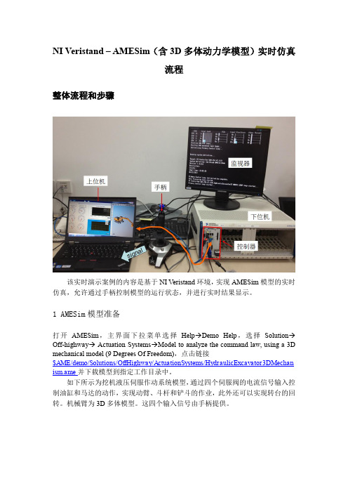
NI Veristand – AMESim(含3D多体动力学模型)实时仿真流程整体流程和步骤该实时演示案例的内容是基于NI Veristand环境,实现AMESim模型的实时仿真,允许通过手柄控制模型的运行状态,并进行实时结果显示。
1 AMESim模型准备打开AMESim,主界面下拉菜单选择Help→Demo Help,选择Solution→Off-highway→ Actuation Systems→Model to analyze the command law, using a 3D mechanical model (9 Degrees Of Freedom),点击链接$AME/demo/Solutions/OffHighway/ActuationSystems/HydraulicExcavator3DMechan ism.ame并下载模型到指定工作目录中。
如下所示为挖机液压伺服作动系统模型,通过四个伺服阀的电流信号输入控制油缸和马达的动作,实现动臂、斗杆和铲斗的作业,此外还可以实现转台的回转。
机械臂为3D多体模型。
这四个输入信号由手柄提供。
首先对模型进行简化处理,保证模型能够进行定步长计算,计算步长最好控制在0.1~1ms之间,简化过程此处不再赘述。
经过简化,模型能够使用Euler算法以0.1ms步长运行,计算结果与变步长结果一致。
添加Veristand接口,定义四个输入,将输入和对应伺服阀的信号输入端口连接。
编译进入parameter模式(注:自定义的global parameter可被Veristand识别,并允许在实时运行时修改,藉此实现在线调参。
本例中不考虑)。
进入simulation模式,在watch variables对话框中拖入所需要进行实时显示的结果(variable),并进行命名(修改title)。
这些变量将会出现在Veristand的映射列表中。
设定打印间隔(print interval)选择定步长模式、算法和计算步长。
NI_VeriStand_2010_使用手册
Real-Time Testing and Simulation SoftwareNI VeriStand 2010使用手册Document Version 1.0By 慕慕316395914目录1.概述 (3)2.创建软件模型 (4)2.1.创建被控对象模型 (4)2.2.创建控制器模型 (9)3.创建MIL测试环境 (11)4.创建测试激励信号 (20)4.1.使用S TIMULUS P ROFILE E DITOR (20)4.2.使用TMDS F ILE V IEWER (26)5.VERISTAND高级功能 (28)5.1.使用U SER C HANNELS、P ROCEDURES、A LARMS (28)5.2.使用C ALCULATED C HANNELS (33)6.创建HIL测试系统 (39)6.1.添加实时目标机 (39)6.2.添加NI DAQ设备 (41)6.3.添加NI R系列设备 (43)6.4.添加NI故障注入模块 (44)6.5.添加NI C OMPACT RIO硬件 (47)6.6.添加NI XNET硬件 (48)6.7.添加TDK-L AMBDA可编程电源 (53)6.8.更改软硬件端口映射 (57)6.9.更改模型运行设置 (58)1.概述VeriStand 2010是美国National Instruments公司专门针对HiL仿真测试系统而开发出的软件环境。
VeriStand 2010是一种基于配置的软件环境,它简单易用,无需编程就完成实时测试系统的创建,实现HiL测试中所需的各种功能。
NI VeriStand 2010能够配置模拟、数字和基于FPGA的硬件I/O接口;能够配置激励生成、记录数据、计算通道和事件警报;能够从NI LabVIEW和MathWorks Simulink®等建模环境中导入控制算法和仿真模型;能够利用操作界面实时在线监控运行任务并与之交互。
veristand 使用手册
veristand 使用手册VeriStand 是一款用于实时测试和仿真的软件平台,它可以帮助工程师进行各种各样的应用开发和集成测试。
本使用手册将为您介绍VeriStand 平台的基本功能、操作步骤以及常见问题的解决方法,旨在帮助您更好地理解和使用 VeriStand。
一、VeriStand 简介VeriStand 是由 National Instruments(以下简称 NI)开发的实时测试和仿真软件平台,它提供了一个可视化环境,用于配置和运行实时测试和仿真应用。
VeriStand 的主要特点包括:1. 实时控制:VeriStand 支持与硬件设备实时通信,实现对被测系统的实时控制和监测。
2. 数据采集和分析:VeriStand 可以采集和记录传感器数据,并提供丰富的数据分析工具,帮助用户对测试结果进行详细的分析和评估。
3. 用户自定义:VeriStand 提供了可扩展的架构,用户可以通过自定义功能和自定义界面来满足特定的测试需求。
4. 平台互操作性:VeriStand 可以与其他 NI 工具以及第三方软件进行集成,实现整个测试生命周期的无缝衔接。
二、VeriStand 系统要求在开始使用 VeriStand 之前,请确保您的计算机满足以下最低系统要求:1. 操作系统:Windows 7/8/10(64 位)。
2. 处理器:双核 2 GHz 或更高。
3. 内存:8 GB 或更高。
4. 硬盘空间:至少 30 GB 的可用空间。
5. 显卡:支持 DirectX 9 或更高版本。
三、VeriStand 安装步骤1. 下载安装程序:从 NI 官方网站下载 VeriStand 安装程序。
2. 运行安装程序:双击安装程序并按照提示完成安装向导。
3. 接受许可协议:阅读并接受 VeriStand 的许可协议。
4. 选择安装位置:选择您希望安装 VeriStand 的目标文件夹。
5. 完成安装:点击“安装”按钮开始安装 VeriStand。
NI VeriStand Model Framework用户指南说明书

INTRODUCTIONNI VeriStand Model Framework™The NI VeriStand software and the NI LabVIEW Model Interface Toolkit allow you to run simulations of your simulation models written in C and C++. To enable your models to interact with this NI software, you must design them to work with the NI VeriStand Model Framework, a group of files that provide entry points to your models.This guide describes the components of the NI VeriStand Model Framework, the process for creating model code that is compatible with the framework, and requirements for compiling your model with the framework.ContentsInteraction of Framework Code and Your Model Code (1)Installing the Model Framework (2)Components of the Model Framework (3)Components of Your Model Code (3)Overview: Model Creation and Compilation Process (4)Creating a model.h Header File (4)Adapting template.c to Serve as Your Model Code (5)Compiling Your Model with the NI VeriStand Model Framework (5)Where to Go Next (6)Interaction of Framework Code and Y our Model CodeWhen you run your test application, designed using NI VeriStand or the LabVIEW Model Interface Toolkit, the application executes functions defined in NI VeriStand Model Framework files. These functions then call functions in your model code, which convert user-defined data types, initialize your model, and take a time step.The following illustration shows how NI software, Model Framework code, and code in your model interact. In this illustration, your test application calls a function that the Model Framework exports. That function in turn calls a function in your model code.Figure 1. Interaction of NI Software, Framework Code, and Model CodeAs the model executes, the test application can interact with the model in the following ways:•Write data to model inports•Read data from model outports•Allow you to adjust model parameter values•Allow you to probe model signalsInstalling the Model FrameworkIn the NI VeriStand installer, the NI VeriStand Model Framework feature installs the Model Framework files on the host computer. If you cannot locate the files described in the next section of this document, run the NI VeriStand installer again and select the NI VeriStand Model Framework item from the list of features to install. You do not need to reinstall other NIsoftware to install the Model Framework.2||NI VeriStand Model Framework IntroductionNI VeriStand Model Framework Introduction |© National Instruments |3Components of the Model FrameworkThe following table describes the files in the Model Framework. These files describe how you must implement your model code.Components of Y our Model CodeYou typically create the following two files to implement your C/C++ model:•model.h —Contains the type definitions for your model parameters. This file must be named model.h and must include all the user-visible parameters in your model.•model.c —Contains your model code. Make a copy of template.c and modify the copy to ensure you maintain interdependent structures, such as headers, imported and exported symbols, and functions NI software recognizes, between your model code and ni_modelframework.c . You can name this .c file however you want.The next section of this document contains information about creating your model.h and .c files.FileDescription Installed Location ni_modelframework.h A header file that includes thefollowing components:•Type definitions that your model code can use to define properties of outward-facing components of your model, such as inports, outports, parameters, and signals.•Functions the NI VeriStand Model Framework exports to your compiled model.RootDrive :\VeriStand\version \ModelInterfacewhere RootDrive is the drive where NI software installs and version is the version number of NI VeriStand.ni_modelframework.c Implements the commoninterface between your test application and your model code.RootDrive :\VeriStand\version \ModelInterface\custom\srctemplate.c A template for your model code. Use this file to create code that maintains interdependent structures between your model and ni_modelframework.c .RootDrive :\VeriStand\version \ModelInterface\custom\examples4| |NI VeriStand Model Framework Introduction Overview: Model Creation and Compilation ProcessTo create a model written in C/C++ that NI software can load and execute via the Model Framework, you typically perform the following tasks:1.Create a model.h header file.2.Adapt template.c to serve as your model code.3.Create a makefile to compile your model code.The following sections contain high-level guidelines about the files you need to create and customize to prepare a model for use by NI software. However, these sections do not contain detailed instructions for creating and compiling a model using the Model Framework. For details about this process, refer to code comments inside the Model Framework files.Creating a model.h Header FileYou must create a header file named model.h for your model code. The model.h file contains the type definitions for model parameters and must include all the user-visible parameters in your model.The following code, copied from the model.h file in the engine model example atRootDrive :\VeriStand\version \ModelInterface\custom\examples\engine , provides an example of the model.h file you must create.Figure 2. Example model.h fileThe previous example contains definitions for both scalar and vector double parameters. For information about defining parameters whose data type is something other than double, refer to TO DO comments in the template.cfile installed by the Model Framework.NI VeriStand Model Framework Introduction |© National Instruments |5Adapting template.c to Serve as Y our Model Code The template.c file installed by the Model Framework serves as a starting point for your model code. You can save your C model file with any filename.Use the following guidelines to modify template.c to serve as your own model code:1.Refer to the contents of template.c for all the code you must customize, which is marked with TO DO comments. This file also contains information about how to instantiate and access parameters.2.Refer to the contents of ni_modelframework.h for the type definitions you must use to define properties of outward-facing components of your model, such as inports, outports, parameters, and piling Y our Model with the NI VeriStand Model FrameworkFor your model code to work with the NI VeriStand Model Framework, you must compile the model. To compile your model, create a makefile that is appropriate for the compiler you plan to use and the operating system on which the model will run. The following list describes the type of makefile to use and the corresponding output to generate:•Windows/NI ETS targets—Create a .mak makefile that generates a DLL. Refer to the National Instruments website at /info and enter the Info Code exjr6s for information about compiling a DLL for ETS targets.•VxWorks targets—Create a .mk makefile that generates a .out file. Refer to the National Instruments website at /info and enter the Info Code ex2xp2 for information about compiling a .out file for VxWorks targets.Note To determine which real-time operating system your RT target runs, refer to the National Instruments website at /info and enter the Info Code exxjax .Refer to the example .mak and .mk files installed in the RootDrive :\VeriStand\version \ModelInterface\custom\examples directory, where RootDrive is the drive where NI software installs and version is the version number of NI VeriStand, for examples of makefiles designed to compile models that work with the Model Framework.The following files must be present when you run a makefile to compile your model code:•ni_modelframework.h •ni_modelframework.c•model.h•model.c© 2009–2015 National Instruments. All rights reserved.372952C-01Aug15Refer to the NI Trademarks and Logo Guidelines at /trademarks for more information on National Instruments trademarks. Other product and company names mentioned herein are trademarks or trade names of their respective companies. For patents covering National Instruments products/technology, refer to the appropriate location: Help»Patents in your software, the patents.txt file on your media, or the National Instruments Patents Notice at /patents . You can find information about end-user license agreements (EULAs) and third-party legal notices in the readme file for your NI product. Refer to the Export Compliance Information at /legal/export-compliance for the National Instruments global trade compliance policy and how to obtain relevant HTS codes, ECCNs, and other import/export data. NI MAKES NO EXPRESS OR IMPLIED WARRANTIES AS TO THE ACCURACY OF THE INFORMATION CONTAINED HEREIN AND SHALL NOT BE LIABLE FOR ANY ERRORS. U.S. Government Customers: The data contained in this manual was developed at private expense and is subject to the applicable limited rights and restricted data rights as set forth in FAR 52.227-14, DFAR 252.227-7014, and DFAR 252.227-7015.Where to Go NextThe Model Framework installs several example models, including their .c and model.h files and makefiles. Refer to the RootDrive :\VeriStand\version \ModelInterface\custom\examples directory, where RootDrive is the drive where NI software installs and version is the version number of NI VeriStand, for examples of model code you can explore.Refer to the appropriate help system for the NI software you are using:•NI VeriStand Help —Available in NI VeriStand by selecting Help»Search the NI VeriStand Help . Browse to the Integrating and Executing Models section on the Contents tab for more information about simulating models in NI VeriStand.•Model Interface Toolkit Help —Available in LabVIEW by selecting Help»LabVIEW Help . Browse to the Toolkits»Model Interface Toolkit section on the Contents tab for more information about simulating models in LabVIEW with the Model Interface Toolkit.。
什么是NI VeriStand
什么是NI VeriStandNI VeriStand 引擎是非可见执行机制,负责执行硬件I/O、模型、过程、预警和在系统定义文件中指定的其他测试系统任务。
引擎不但控制囫囵系统的定时,而且控制NI VeriStand 引擎和工作区的主机之间的通信。
NI VeriStand 引擎包括多个定时循环,其执行定时由硬件大事控制,精度为微妙。
确定性内存缓冲器在不同循环任务间提供通信,不会在引擎执行中引起数据颤动。
采纳多循环架构,NI VeriStand引擎自然利用了多核处理器并行处理能力的优势,提升了系统性能。
创建系统定义时,包括在高吞吐量、并行性和低延时、挨次结构间挑选的能力,可以配置各种不同的引擎执行设置。
此外,NI VeriStand引擎发布了各种系统参数,您可以在运行时拜访。
或者您可以用法NI 实时执行跟踪工具更细致地查看您的应用程序的执行。
引擎的实时I/O任务用法硬件定时,单点I/O结构,是仿真,控制,和逐点分析任务的抱负挑选。
然而,用法NI VeriStand定制设备可以添加对较高速率,缓冲信号生成和采集的支持,这些内容将会在下一节举行研究。
NI VeriStand引擎可以在NI PCI,NI 实时系统,还有NI CompactRIO 和具有128MB或更大的DRAM RIO接口上的单板RIO上运行。
实时系统使您能够结合同步I/O确定性地执行您的测试——这对于实现闭环控制或与真切组件交互的系统仿真应用程序来说是关键的能力。
然而,对于低性能系统需求或实现模型在环(MIL)或软件在环(SIL)的测试,您还可以在同一台计算机上将NI VeriStand 引擎作为您的用户界面加以运行。
自定义NI VerStandNI VeriStand通过用法基于配置的开发办法,为创建实时测试应用程序提供软件架构。
实时测试应用程序所需要的全部常见任务已经在NI VeriStand引擎内部举行了实现与优化。
然而,您还可以用法LabVIEW第1页共3页。
实验一NIELVIS工作环境的熟悉和使用

实验一NIELVIS工作环境的熟悉和使用实验一NI ELVIS工作环境的熟悉和使用一、实验目的1、熟悉NI ELVIS的工作环境,了解系统的主要构成和功能。
2、使用虚拟仪器进行电子元件参数测量。
3、练习基于ELVIS的电路分析。
二、实验原理1、NI ELVISI工作环境(NI Educational Laboratory Virtual Instrumentation Suite)电子学教育平台包括Multisim, ELVIS和LabVIEW。
该软硬件集成的平台可以无缝地将电路理论、设计仿真、原型比较联系起来,以动手实践方式培养学生电子设计理论和实践的能力。
NI ELVIS II环境由以下几部分组成:1.硬件工作区——用于创建电路及接口实验2.NI ELVIS II软件(在NI LabVIEW软件中实现),包括以下:●软前面板(SFP)工具示波器(Scope)函数发生器(FGEN)数字万用表(DMM)任意波形发生器(ARB)波特图分析仪(Bode)二线电流电压分析仪(2-Wire)三线电流电压分析仪(3-Wire)动态信号分析仪(DSA)阻抗分析仪(Imped)数字读取器(DigOut)数字写入器(DigIn)可变电源(手动控制)(VPS)●LabVIEW应用程序编程接口(API)●Multisim应用程序编程接口(API)通过API,用户可使用在Multisim内编写的LabVIEW程序及仿真程序实现NI ELVIS II工作站的自定义控制及访问。
图1- 1 NI ELVIS II 工作站详细信息三、实验内容练习1-1 测量器件值1、使用提供的USB线将NI ELVIS II+工作站与计算机连接。
2、在计算机:所有程序——>National Instruments——>NI ELVISmx for NI ELVIS & NI MyDAQ——> NI ELVISmx Instruments Launch,或点击桌面快捷方式。
Ni VeriStand数据采集模块远程数据采集模块
数据采集模块远程数据采集模块Ni VeriStand是一种配置实时测试应用程序的软件环境。
即买即用的NI VerStand有助于您配置针对多核处理器的实时引擎,以执行以下任务:· 模拟、数字、通信总线,和基于现场可编程门阵列(FPGA)的I/O接口· 可触发,多文件数据记录· 实时激励生成· 计算通道· 事件预警和预警响应程序NI VeriStand 还能够从NI LabVIEW 软件和第三方环境中导入控制算法,仿真模型和其他任务。
您可以使用运行时可编辑的用户界面监测这些任务,并与其交互,该界面包含许多用于强制赋值、警报监控、I/O校准、激励配置编辑的有效工具。
NI VeriStand的使用不需要掌握编程知识,但是可以在多种不同的软件环境进行自定义和扩展,如NI LabVIEW,ANSI C/C++,和其他建模和编程环境。
NI VeriStand 面向实时测试应用实时测试中将实时操作系统作为测试系统的一部分。
与使用通用操作系统相比,推动实时测试系统最常见的需求是需要实现更高的可靠性和更高的性能。
实时测试系统的一个实例是硬件回路测试仿真器,在该系统中,必须确定性地执行系统模型,以提供在物理上不属于测试组件的准确仿真。
使用闭环控制的应用程序是另一种实时测试应用。
这些系统必须自动控制测试系统某部分,如温室,通过传感器交互,确定性定点设置的变化以实现达到系统的预想状态。
系统也必须检测并对预警条件迅速地作出响应,这有助于防止操作人员受伤或对测试系统造成损害。
与这些应用程序类似,测试单元激励和检测应用程序都已经拥有一个完整的控制系统,或者不需要闭环控制,只需要能够提供确定性激励生成和测试单元检测的工具。
这些实时测试应用程序必需的核心功能已经实现,并在NI VeriStand架构上进行了优化——可以配置并使用。
这包括主接口通信、数据记录、激励生成、预警检测和响应,以及算法和模型执行。
NI_VeriStand使用手册
Real-Time Testing and Simulation SoftwareNI VeriStand 2010使用手册Document Version 1.0By 慕慕316395914目录1.概述 (3)2.创建软件模型 (4)2.1.创建被控对象模型 (4)2.2.创建控制器模型 (9)3.创建MIL测试环境 (12)4.创建测试激励信号 (21)4.1.使用S TIMULUS P ROFILE E DITOR (21)4.2.使用TMDS F ILE V IEWER (27)5.VERISTAND高级功能 (29)5.1.使用U SER C HANNELS、P ROCEDURES、A LARMS (29)5.2.使用C ALCULATED C HANNELS (34)6.创建HIL测试系统 (40)6.1.添加实时目标机 (40)6.2.添加NI DAQ设备 (42)6.3.添加NI R系列设备 (44)6.4.添加NI故障注入模块 (45)6.5.添加NI C OMPACT RIO硬件 (48)6.6.添加NI XNET硬件 (49)6.7.添加TDK-L AMBDA可编程电源 (54)6.8.更改软硬件端口映射 (58)6.9.更改模型运行设置 (59)1.概述VeriStand 2010是美国National Instruments公司专门针对HiL仿真测试系统而开发出的软件环境。
VeriStand 2010是一种基于配置的软件环境,它简单易用,无需编程就完成实时测试系统的创建,实现HiL测试中所需的各种功能。
NI VeriStand 2010能够配置模拟、数字和基于FPGA的硬件I/O接口;能够配置激励生成、记录数据、计算通道和事件警报;能够从NI LabVIEW和MathWorks Simulink®等建模环境中导入控制算法和仿真模型;能够利用操作界面实时在线监控运行任务并与之交互。
- 1、下载文档前请自行甄别文档内容的完整性,平台不提供额外的编辑、内容补充、找答案等附加服务。
- 2、"仅部分预览"的文档,不可在线预览部分如存在完整性等问题,可反馈申请退款(可完整预览的文档不适用该条件!)。
- 3、如文档侵犯您的权益,请联系客服反馈,我们会尽快为您处理(人工客服工作时间:9:00-18:30)。
NI VeriStand 使用手册(概述|建模|创建MiL环境)目录1. 概述32. 创建软件模型42.1. 创建被控对象模型42.2. 创建控制器模型93. 创建MIL测试环境114. 创建测试激励信号204.1. 使用STIMULUS PROFILE EDITOR 204.2. 使用TMDS FILE VIEWER 265. VERISTAND高级功能285.1. 使用USER CHANNELS、PROCEDURES、ALARMS 285.2. 使用CALCULATED CHANNELS 336. 创建HIL测试系统396.1. 添加实时目标机396.2. 添加NI DAQ设备416.3. 添加NI R系列设备436.4. 添加NI故障注入模块446.5. 添加NI COMPACT RIO 硬件476.6. 添加NI XNET硬件486.7. 添加TDK-LAMBDA可编程电源536.8. 更改软硬件端口映射576.9. 更改模型运行设置581. 概述VeriStand是美国National Instruments公司专门针对HiL仿真测试系统而开发出的软件环境。
VeriStand 是一种基于配置的软件环境,它简单易用,无需编程就完成实时测试系统的创建,实现HiL测试中所需的各种功能。
NI VeriStand能够配置模拟、数字和基于FPGA的硬件I/O接口;能够配置激励生成、记录数据、计算通道和事件警报;能够从NI LabVIEW和MathWorks Simulink®等建模环境中导入控制算法和仿真模型;能够利用操作界面实时在线监控运行任务并与之交互。
本文介绍了NI Veristand 各项主要功能的使用方法,并按照通用的开发测试顺序编写,主要内容包括:@创建软件模型;@创建MiL测试系统;@实现自动化测试、记录数据;@创建HiL测试系统。
2. 创建软件模型NI VeriStand可以利用*.dll文件导入由Matlab/Simulink/Stateflow创建的算法或仿真模型,下图所示为Simulink模型导入NI VeriStand的过程:注意:NI VeriStand 支持的编译器包括Microsoft Visual C++ 6.0, .NET 2003, 2005 (Professional or Express), or 2008 (Professional or Express).在本章中具体介绍了上述过程的操作步骤,将一个在Matlab/Simulink环境下创建的*.mdl文件转换为NI VeriStand所支持的*.dll文件。
下面用到的仿真模型来自Matlab / Simulink的Demos:•发动机Engine模型:Modeling Engine Timing Using Triggered Subsystems•控制器ECU模型:Engine Timing Model with Closed Loop Control2.1. 创建被控对象模型下面过程将演示如何将Simulink中的发动机Engine模型,转换为VeriStand可用的被控对象模型。
1. 打开Simulink模型:Modeling Engine Timing Using Triggered Subsystem另存到新建工作目录中,例如D:\NIVS_HandsOn,为避免和原有模型冲突,重命名为Engine.mdl该发动机模型要求的输入信号为•Throttle Angle 节气门开度•Drag Torque 拖拽扭矩(负载扭矩)输出信号为•Engine Speed 发动机转速关于该模型的具体信息,请参考Simulink帮助文档。
运行后结果如下所示,上图为发动机模型所需输入信号,黄色曲线为负载扭矩,紫色曲线为节气门开度;下图中为发动机模型计算的输出信号,黄色曲线为发动机转速。
1) 0~5s,节气门开度不变,负载扭矩在2s时,由25 Nm 下降到20 Nm,发动机转速因负载扭矩变小而提高;2) 5s时,节气门开度增加,负载不变时,发动机转速快速升高;3) 8s时,负载扭矩再次增加,节气门开度不变,转速下降。
2. 正确安装VeriStand后,在Simulink Library Browser 中会自动添加NI VeriStand Blocks,如下图所示:3. 修改模型1) 将模型中需要做映射的端口,用相应的NIVeriStand In 和NIVeriStand Out 替代;2) 在Simulink模型最上层中添加Block NIVeriStandSignalProbe,添加后下层所有模块的参数也都可以通过VeriStand观测或者修改;3) 取消原Simulink模型中Signal Properties下有关data logging的选项。
4) 完成修改后的发动机模型如下所示:4. 设置编译环境并编译1) 打开Simulink模型的Configuration Parameters (快捷键:Ctrl+E),2) 在Real-Time Workshop中,指定System target file为NIVeriStand.tlc,点击OK确认。
注意:如果实时目标机为cRIO系列,此处要选择NIVeriStand_VxWorks.tlc3) 回到Solver页面,选择定步长求解器:fixed step-size ordinary differential equation (ODE) solver 注意:NI VeriStand只支持使用定步长的常微分方程求解器4) 指定步长:Fixed-step size (fundamental sample time)为0.001,也就是1kHz注意:步长越小仿真模型计算越准确,但相应的会消耗更多技术资源。
修改完步长后,要再次运行仿真模型,观察结果,既要避免因步长选择过大,出现如无法收敛,计算精度无法满足要求,又要避免过小的步长造成cpu运算负担过大,影响实时性。
5) 点击Incremental Build图标或者Ctrl + B,开始编译6) 编译成功后,Matlab的Command Windows中出现下列提示,### Successful completion of Real-Time Workshop build procedure for model: ModelName,并生成与Engine.mdl同名的Engine.dll文件,保存在新生成的Engine_niVeriStand_rtw文件夹内。
2.2. 创建控制器模型在Simulink提供的Demo Engine Timing Model with Closed Loop Control中包含了控制器ECU的算法。
我们需要把其中的控制器(Controller)算法从闭环模型中分割出来,建立单独的ECU模型,并编译为对应的*.dll文件。
Controller采用PI控制算法,可根据目标发动机转速,结合发动机模型中的负载扭矩,计算出节气门开度,最终使发动机实际转速与目标转速一致。
下图中黄色曲线为发动机负载曲线,紫色曲线为控制器输出的节气门开度1) 2s时,由25 Nm变为20 Nm2) 8s时,由20 Nm变为25 Nm1. 分割、修改ECU模型1) 打开所需的Demo:Engine Timing Model with Closed Loop Control2) 提取模型中的Controller子模块3) 添加NIVeriStand In、NIVeriStand Out和NIVeriStandSignalProbe,另存为Ecu.mdl。
2. 设置编译环境并编译,最终生成所需的Ecu.dll文件。
具体配置过程请参考发动机模型转换部分。
3. 创建MiL测试准备好了Engine和Ecu的软件模型,在本章中,将其导入到NI VeriStand 中,创建一个MiL (Model-in-the-Loop) 测试环境,并介绍如何在Work Space中添加控件,控制和观察Engine、Ecu的行为。
1. 运行NI VeriStandStart » Program Files » National Instruments » NI VeriStand» NI VeriStand.2. 新建一个项目(Create a new project).1) 选择File » New Project.2) 在Project Name中输入项目名称:ecu hil hands on.3) 指定项目根目录Project Root Folder 到<Public Documents>\National Instruments\NI VeriStand\Projects4) 勾选Create folder for project.5) 点击OK确认.3. 点击Configure Project, 打开项目浏览器Project Explorer.项目浏览器(Project Explorer) 用于配置测试所需的全部设置。
通过Project Explorer可以部署(Deploy)和运行(Run)系统定义文件。
项目浏览器包括所有运行和自动化测试所需关键的参数,同时也可以添加定制文件。
4. 展开System Definition File 节点.5. 鼠标右键单击<ProjectName>.nivssdf 文件,选择Launch System Explorer.系统浏览器(System Explorer) 用于创建NI Veristand系统定义文件。
系统定义文件是一个配置NI Veristand引擎特性的文件。
通过添加,删除和修改位于系统浏览器左部的各项配置可以定义各种属性,包括NI VeriStand引擎的执行方式、硬件端口、计算通道、对仿真模型的控制、报警,执行顺序以及管理通道之间的映射关系。
完成系统定义文件的设置后,它将被部署到NI VeriStand 引擎并开始运行。
6. 添加发动机Engine模型1) 展开Targets » Controller,点击Simulation Models;2) 添加模型Add Simulation Model.3) 将目录转换到Engine.dll所在目录4) 选择Engine.dll,单击OK.确认;发动机模型有2个输入(节气门开度和负载扭矩) 和1个输出(发动机输出)。
7. 添加控制器ECU模型1) 点击Simulation Models,添加仿真模型Add Simulation Model;2) 选择Ecu.dll,单击OK 确认。
