Neo_M590E模块硬件设计指南(邮票孔) V1.0
LMZ10501和LMZ10500SIMPLE SWITCHER nano 模块评估板用户指南说明书

User's GuideSNVA491B–August2011–Revised April2013 AN-2166LMZ10501and LMZ10500SIMPLE SWITCHER®Nano Module Evaluation Board1IntroductionThe LMZ10501and LMZ10500SIMPLE SWITCHER nano modules are easy-to-use DC-DC solutionsoptimized for space-constrained applications.The LMZ10501is capable of driving up to1A load withexcellent power conversion efficiency,line and load regulation,and EMI performance.The LMZ10500is a 650mA version module and is pin-to-pin compatible with the LMZ10501.The LMZ10501and LMZ10500Evaluation Board is configured for1.8V output voltage from2.7V to5.5Vinput.The resistor voltage divider RT and RBset the output voltage.The external capacitor CVCbypassesthe VCON pin and provides additional soft start time.for component selection and device informationdetails,see the device-specific data sheet.The board features additional component footprints for various device enabling schemes and AC signal injection terminals for feedback loop measurements.The evaluation board with its default Bill of Materials offers great EMI performance,complying with the EN 55022Class B radiated emissions standard.2Board Specifications•VIN=2.7V to5.5V•VOUT=1.8V(default setting)•1A max load(LMZ10501)•650mA max load(LMZ10500)•2MHz switching frequency•4layers PCB with1oz copper• 4.3x4.3cm(1700x1700mil)PCB size•Low radiated EMI(EN55022Class B compliant)SIMPLE SWITCHER is a registered trademark of Texas Instruments.All other trademarks are the property of their respective owners.1 SNVA491B–August2011–Revised April2013AN-2166LMZ10501and LMZ10500SIMPLE SWITCHER®Nano ModuleEvaluation Board Submit Documentation FeedbackCopyright©2011–2013,Texas Instruments IncorporatedTypical Performance Characteristics 3Typical Performance CharacteristicsOutput RippleRadiated EMI2AN-2166LMZ10501and LMZ10500SIMPLE SWITCHER ®Nano Module SNVA491B–August 2011–Revised April 2013Evaluation BoardSubmit Documentation FeedbackCopyright ©2011–2013,Texas Instruments IncorporatedOPTIONAL COMPONENT FOR AC INJECTION FOR CONTROL LOOP MEASUREMENTSBOARD EDGE PAD ASSIGNMENTS FOR QUICK CONNECTIONOPTIONALPLACE CIN AS CLOSE AS POSSIBLE TO THE PVIN AND PGND PINS FOR GOOD BYPASSRESISTORS RT AND RB SET THE OUTPUTVOLTAGEPLACE C VC AS CLOSE AS POSSIBLE TO THE VCONAND SGND PINSENABLE OPTComponents marked with (*) are notpopulated on the board Evaluation Board Schematic and Bill of Materials4Evaluation Board Schematic and Bill of MaterialsFigure 1.Evaluation Board SchematicTable 1.LMZ10501and LMZ10500Bill of Materials,V IN =2.7V to 5.5V,V OUT =1.8V,I OUT (MAX)=1000mA /650mADesignatorDescription Case Size Manufacturer Manufacturer P/N QuantityU1SIMPLE SWITCHERSE08A Texas InstrumentsLMZ10501SE or 1Nano Module LMZ10500SE C IN ,C OUT10µF,X5R,10V0805KEMET C0805C106K8PACTU 2C VC 1000pF 0603TDK C1608C0G2A102J 1R B 82.5k Ω0603Vishay-Dale CRCW060382K5FKEA 1R T 187k Ω0603Vishay-Dale CRCW0603187KFKEA 1R EN1k Ω0603Vishay-Dale CRCW06031K00FKEA 1(optional)R INJ10Ω0603Vishay-DaleCRCW060310R0FKEA1(optional)3SNVA491B–August 2011–Revised April 2013AN-2166LMZ10501and LMZ10500SIMPLE SWITCHER ®Nano ModuleEvaluation BoardSubmit Documentation FeedbackCopyright ©2011–2013,Texas Instruments IncorporatedEvaluation Board Layout 4.1Optional Components and Footprints•RINJ resistor–allows for a network analyzer connection to measure the control loop response.Replacethis resistor with a short in a final design if control loop measurements are not needed.•RPU resistor–an optional footprint to pull EN up to VINwith an external resistor.EN is internally pulledup to VINby a790kΩresistor.•REN–an optional resistor in series with the EN pin.•RPD –an optional pull-down resistor for the QENgate.•QEN–an optional footprint to use an N-ch MOSFET as a pull-down device for EN.•J1–jumper to select how to drive EN.Connecting the jumper pins1and2allows for driving ENdirectly from the EN turret at the edge of the board.Connecting the jumper pins2and3allows fordriving the gate of the pull-down device QEN.•EC1–board edge connector for quick testing.•COUT footprints–the solder mask on the VOUTside of the board is removed to allow for different outputcapacitor configurations.5Evaluation Board LayoutFigure2.Evaluation Board Top View4AN-2166LMZ10501and LMZ10500SIMPLE SWITCHER®Nano Module SNVA491B–August2011–Revised April2013 Evaluation Board Submit Documentation FeedbackCopyright©2011–2013,Texas Instruments Incorporated Evaluation Board LayoutFigure3.Evaluation Board Bottom ViewFigure4.Evaluation Board Assembly(DNP=not populated components)5 SNVA491B–August2011–Revised April2013AN-2166LMZ10501and LMZ10500SIMPLE SWITCHER®Nano ModuleEvaluation Board Submit Documentation FeedbackCopyright©2011–2013,Texas Instruments Incorporated30 mV/Div250 MHz BW500 µs/DivCOUT = 10 F 10V 0805 X5RLOAD CURRENTOUTPUT VOLTAGE500 mA/Div 10 mV/Div500 MHz BW1 µs/DivCOUT = 10 F 10V 0805 X5RVOUT RIPPLETypical Performance for V OUT =1.8V6Typical Performance for V OUT =1.8VUnless otherwise specified the following conditions apply:V IN =5V,I OUT =1A,T A =25°C6AN-2166LMZ10501and LMZ10500SIMPLE SWITCHER ®Nano Module SNVA491B–August 2011–Revised April 2013Evaluation BoardSubmit Documentation FeedbackCopyright ©2011–2013,Texas Instruments IncorporatedCf = 0603YD105MAT AVXLf = VLS252015T-1R0N1R7 TDKTypical Performance for V OUT =1.8VInput LC Filter for Conducted EMI 7SNVA491B–August 2011–Revised April 2013AN-2166LMZ10501and LMZ10500SIMPLE SWITCHER ®Nano ModuleEvaluation BoardSubmit Documentation FeedbackCopyright ©2011–2013,Texas Instruments IncorporatedTypical Performance for V OUT =1.8V8AN-2166LMZ10501and LMZ10500SIMPLE SWITCHER ®Nano Module SNVA491B–August 2011–Revised April 2013Evaluation BoardSubmit Documentation FeedbackCopyright ©2011–2013,Texas Instruments Incorporated Other Output Voltage Settings7Other Output Voltage SettingsFigure 5.V OUT =1.2VFigure 6.V OUT =2.5VFigure 7.V OUT =3.3VFor other output voltages,choose R T =80k Ωto 300k ΩThen calculate R B usingR B =V OUT x R T /(5.875V –V OUT )(1)9SNVA491B–August 2011–Revised April 2013AN-2166LMZ10501and LMZ10500SIMPLE SWITCHER ®Nano ModuleEvaluation BoardSubmit Documentation FeedbackCopyright ©2011–2013,Texas Instruments IncorporatedIMPORTANT NOTICETexas Instruments Incorporated and its subsidiaries(TI)reserve the right to make corrections,enhancements,improvements and other changes to its semiconductor products and services per JESD46,latest issue,and to discontinue any product or service per JESD48,latest issue.Buyers should obtain the latest relevant information before placing orders and should verify that such information is current and complete.All semiconductor products(also referred to herein as“components”)are sold subject to TI’s terms and conditions of sale supplied at the time of order acknowledgment.TI warrants performance of its components to the specifications applicable at the time of sale,in accordance with the warranty in TI’s terms and conditions of sale of semiconductor products.Testing and other quality control techniques are used to the extent TI deems necessary to support this warranty.Except where mandated by applicable law,testing of all parameters of each component is not necessarily performed.TI assumes no liability for applications assistance or the design of Buyers’products.Buyers are responsible for their products and applications using TI components.To minimize the risks associated with Buyers’products and applications,Buyers should provide adequate design and operating safeguards.TI does not warrant or represent that any license,either express or implied,is granted under any patent right,copyright,mask work right,or other intellectual property right relating to any combination,machine,or process in which TI components or services are rmation published by TI regarding third-party products or services does not constitute a license to use such products or services or a warranty or endorsement e of such information may require a license from a third party under the patents or other intellectual property of the third party,or a license from TI under the patents or other intellectual property of TI.Reproduction of significant portions of TI information in TI data books or data sheets is permissible only if reproduction is without alteration and is accompanied by all associated warranties,conditions,limitations,and notices.TI is not responsible or liable for such altered rmation of third parties may be subject to additional restrictions.Resale of TI components or services with statements different from or beyond the parameters stated by TI for that component or service voids all express and any implied warranties for the associated TI component or service and is an unfair and deceptive business practice. TI is not responsible or liable for any such statements.Buyer acknowledges and agrees that it is solely responsible for compliance with all legal,regulatory and safety-related requirements concerning its products,and any use of TI components in its applications,notwithstanding any applications-related information or support that may be provided by TI.Buyer represents and agrees that it has all the necessary expertise to create and implement safeguards which anticipate dangerous consequences of failures,monitor failures and their consequences,lessen the likelihood of failures that might cause harm and take appropriate remedial actions.Buyer will fully indemnify TI and its representatives against any damages arising out of the use of any TI components in safety-critical applications.In some cases,TI components may be promoted specifically to facilitate safety-related applications.With such components,TI’s goal is to help enable customers to design and create their own end-product solutions that meet applicable functional safety standards and requirements.Nonetheless,such components are subject to these terms.No TI components are authorized for use in FDA Class III(or similar life-critical medical equipment)unless authorized officers of the parties have executed a special agreement specifically governing such use.Only those TI components which TI has specifically designated as military grade or“enhanced plastic”are designed and intended for use in military/aerospace applications or environments.Buyer acknowledges and agrees that any military or aerospace use of TI components which have not been so designated is solely at the Buyer's risk,and that Buyer is solely responsible for compliance with all legal and regulatory requirements in connection with such use.TI has specifically designated certain components as meeting ISO/TS16949requirements,mainly for automotive use.In any case of use of non-designated products,TI will not be responsible for any failure to meet ISO/TS16949.Products ApplicationsAudio /audio Automotive and Transportation /automotiveAmplifiers Communications and Telecom /communicationsData Converters Computers and Peripherals /computersDLP®Products Consumer Electronics /consumer-appsDSP Energy and Lighting /energyClocks and Timers /clocks Industrial /industrialInterface Medical /medicalLogic Security /securityPower Mgmt Space,Avionics and Defense /space-avionics-defense Microcontrollers Video and Imaging /videoRFID OMAP Applications Processors /omap TI E2E Community Wireless Connectivity /wirelessconnectivityMailing Address:Texas Instruments,Post Office Box655303,Dallas,Texas75265Copyright©2013,Texas Instruments Incorporated。
M590-USB开发板使用说明
深圳市有方科技有限公司
(技术文档)
M590-USB开发板使用说明
V1.0
修订记录
版本号 更改内容 生效年月 V1.0 初始版本
M590-USB开发板使用说明
一、 开发板实物照片
本开发板适用于M590模块。
AT/数据通讯和电源都用标准的USB端口。
二、 接口说明
1.J1为开机的短路跳线,如果接通,相当与开机一直有效。
模块会上电自动开机。
2.指示灯说明:
1)D10为电源指示灯。
2)D12为运行指示灯,连接模块的LIGHT引脚,模块运行过程中按1秒的频率
闪烁,运行过程中只有这一种指示状态。
由于该开发板对外用USB口通讯,而实际上模块还是串口,开发板上有USB转串口的转换芯片,型号是PL2303HX,所以需要在PC上安装USB的驱动程序。
三、 USB驱动程序
PL2303HX驱动程序.rar。
Neo_M590 AT指令集_V3.11
AT+SIGNAL=3:正常状态是闪烁,链接上GPRS后常亮。 AT+SIGNAL=4:正常状态是常灭,链接上 GPRS 后常亮。 对应的模块软件版本是 V1.30c 或者 V1.20u
生效年月 200808 200906 200907
200908 201006
201012
201101
备注:1.30 开头的版本是带服务器功能的版本; 1.20 开头的版本是不带服务器功能的版本。
修订版本,增加切换命令的说明 修订版本,修改 PDU 短信流程,增加发送数据的说明 修订版本,增加 AT+XBANDSEL 指令说明 修订版本,增加身份认证指令注意事项!
201104 201105 201107 201109
修订版本, 1)增加身份认证的用户名长度,原来是 20,修改成 32,对应的软件版 本是 1.30e 2)增加“SOCKETS: IPR STOPPED”的说明 3)增加模块流程注意事项 修订版本, 1) 增加短信设置说明 2) 增加外部协议栈的 AT 流程说明
201203 201204源自深圳市有方科技有限公司版权所有
第 1页,共 65页
有无线,方精彩
目录
1 普通指令.................................................................................................................................................................... 5
拓比易联 PCEye 5 用户手册说明书

Tobii Dynavox PCEye5用户手册User’s manual Tobii Dynavox PCEye5Version1.0.212/2020All rights reserved.Copyright©Tobii AB(publ)未经出版人事先书面许可,对本出版物的任何部分不得进行复制、保存于可检索系统内,也不得以任何形式或任何途径(如电子形式、复印、录制等)传播。
所主张的版权保护包括依成文法或司法规定而受版权保护的材料和信息的所有形式和事项,包括但不限于屏幕(如屏幕显示、菜单等)上所显示软件程序生成的材料。
本文档中所含信息由Tobii Dynavox专有。
未经Tobii Dynavox事先书面授权,禁止复制任何部分或全部内容。
本文档内提及的产品是其相应所有者的商标和/或注册商标。
出版商和作者不对这些商标主张权利。
尽管在本文档的编写过程中采取了各种防范措施,但出版商和作者对本文档的任何错误或遗漏概不负责,对由于使用本文档所含信息或由于使用本文档随附的程序或源代码而引致的任何损失也概不负责。
无论在何种情况下,出版商和作者对本文档直接或间接导致的实际或指称的任何利润损失或其他商业损失一概无须负责。
内容若有更改,恕不另行通知。
请访问Tobii Dynavox网站查看本文档的更新版本。
联系方式:Tobii Dynavox AB Karlsrovägen2D 18253Danderyd Sweden+4686636990拓比电子技术(苏州)有限公司苏州工业园区,星汉街5号,6号楼401室邮编:215021电话:0512-********以下产品受美国专利(专利号:7,572,008、6,659,611、8,185,845与9,996,159)保护:●PCEye5目录内容1介绍 (4)1.1关于警示语的说明 (4)1.2符号与标志 (4)1.3预期用途 (4)1.4产品说明 (4)1.5包装内容 (5)2安全性 (6)2.1安装警告 (6)2.2癫痫警告 (6)2.3红外警告 (6)2.4磁场警告 (6)2.5儿童安全 (6)2.6请勿打开PCEye5 (6)2.7紧急情况 (6)2.8Computer Control (7)2.9第三方 (7)3PCEye5入门 (8)3.1系统要求: (8)4安装PCEye5 (9)4.1标准安装 (9)4.2使用PCEye支架 (9)4.3永久固定 (9)5使用PCEye5 (10)5.1用户位置调整 (10)5.2关于在室外使用的提示 (10)6设置 (11)6.1设置Windows Hello (11)7适用应用程序软件 (12)8产品保养 (13)8.1温度和湿度 (13)8.1.1一般用途 (13)8.1.2运输和储存 (13)8.2清洁 (13)8.3PCEye5的运输 (13)8.4PCEye5的处置 (13)附录A支持和保修 (14)A1客户支持中心 (14)A2保修 (14)附录B合规信息 (15)B1FCC声明 (15)B2加拿大工业部声明 (15)B3CE声明 (15)B4标准 (15)附录C技术规格 (16)1介绍感谢您选购Tobii Dynavox公司的PCEye5设备!为确保获得此产品的最佳性能,请仔细阅读本手册。
亿佰特芯翼XY1100芯片低功耗双核处理器NB-IoT无线通信模组EA01-S使用手册

目录第一章概述 (2)1.1产品简介 (2)1.2特点功能 (2)1.3应用场景 (2)第二章规格参数及引脚定义 (3)2.1主要性能 (3)2.2引脚分配 (4)2.3引脚类型定义 (4)2.4引脚描述 (5)第三章扩展指令和功能说明 (6)3.1AT模式和数据透传模式切换 (6)3.2设备软件重启 (6)3.3省电锁WORKLOCK的应用 (6)3.4串口波特率设置 (7)3.5通信协议类型配置 (7)3.6TCP/UDP透传通道功能配置 (7)3.7心跳包功能配置 (8)3.8注册包功能配置 (9)3.9M ODBUS RTU/TCP转换功能 (10)3.10MQTT应用配置 (10)3.11COAP功能配置 (13)3.12云功能配置 (16)第四章 3GPP标准指令和运营商云平台标准指令 (16)第五章TCP/UDP快速使用指南 (16)5.1上电流程说明 (16)5.2TCP/UDP的S OCKET链路创建和数据通信的应用配置流程 (17)第六章硬件设计 (19)第七章常见问题 (19)7.1传输距离不理想 (19)7.2 模块易损坏 (19)7.3误码率太高 (20)第八章焊接作业指导 (20)8.1回流焊温度 (20)8.2回流焊曲线图 (21)第九章批量包装方式 (22)修订历史 .......................................................................................................................... 错误!未定义书签。
关于我们 .......................................................................................................................... 错误!未定义书签。
有方M590 GPRS模块_PPP_TCP_流程 V1.1
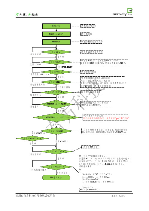
送A T+C G A T T=1\r 返 回O K 返 回+C G A T T:1 1 2)进 发 没 有 返 回O K 返 回O K 送A T+X I I C=1\r 1 3)查 看P P P连 接 是 否 建 立 : 如 返 回+X I I C: 0, 0.0.0.0 O K说 明P P P连 接 尚 未 建 立 ; 如 返 回+X I I C: 1, 1 0.3.1 5 5.2 4 9 O K,或 其 他I P地 址, 说 明P P P连 接 成 功,其 中1 0.3.1 5 5.2 4 9为I P地 址。 代码建议采用 d o { SendAtCmd (”A T+X I I C? \r”) ; S l e e p(3 0 0); / / 延 时3 0 0m s; ReadUart(r e c B u f); / / 判 断r e c B u f的 值,确 认P P P连 接 ... timeout + +; }w h i l e(timeout <5 0); 行P P P连 接
没 有 信 号(9 9,9 9) 发 没有注册上网络 已注册上网络 发 没 有 返 回O K 返 回O K 9)设 置 访 问 节 点 A P N,移 动 为 C M N E T,联 通 为U N I N E T。 发 送 A T+CGDCONT =1,I P,C M N E T\r 没 有 返 回O K 返 发 回O K 1 0)设 置 用 户 身 份 认 证 , 用 户 名 和 密 码 不 能 为 空 ,缺 省 值 是”g sm ” 和”1 2 3 4” 送A T+X I S P=0\r 送A T+C R E G? \r
有无线, 精彩 方
NI sbRIO-9627单板RIOOEM设备使用指南说明书
GETTING STARTED GUIDENI sbRIO-9627Single-Board RIO OEM DevicesThis document describes how to begin using the NI sbRIO-9627.Safety GuidelinesOperate the sbRIO-9627 only as described in the user documentation.Caution The sbRIO-9627 must be installed in a suitable enclosure prior to use.Caution NI makes no product safety, electromagnetic compatibility (EMC), or CEmarking compliance claims for the sbRIO-9627. The end-product supplier isresponsible for conformity to any and all compliance requirements.Caution Exercise caution when designing an enclosure for the sbRIO-9627.Auxiliary cooling may be necessary to keep the sbRIO-9627 within the specifiedoperating temperature range. Refer to the NI sbRIO-9627 Specifications on /manuals for more information about the maximum operating temperature rating. Forinformation and examples regarding factors that can affect thermal performance,visit /info and enter the Info Code sbriocooling.Caution Do not operate the sbRIO-9627 in a manner not specified in thisdocument. Product misuse can result in a hazard. You can compromise the safetyprotection built into the product if the product is damaged in any way. If the productis damaged, return it to NI for repair.Safety VoltagesConnect only voltages that are below these limits.V terminal to C terminal30 VDC maximum, Measurement Category I Measurement Category I is for measurements performed on circuits not directly connected to the electrical distribution system referred to as MAINS voltage. MAINS is a hazardous live electrical supply system that powers equipment. This category is for measurements of voltages from specially protected secondary circuits. Such voltage measurements include signal levels, special equipment, limited-energy parts of equipment, circuits powered by regulated low-voltage sources, and electronics.Caution Do not connect the sbRIO-9627 to signals or use for measurements withinMeasurement Categories II, III, or IV.Preparing the EnvironmentEnsure that the environment in which you are using the sbRIO-9627 meets the following specifications.-40 °C to 85 °CLocal ambient operating temperature neardevice (IEC 60068-2-1, IEC 60068-2-2)Maximum reported onboard sensor temperatureCPU/FPGA temperature98 °CPrimary System temperature85 °CSecondary System temperature85 °CNote Ensure that the local ambient, reported CPU/FPGA, and reported PrimarySystem temperatures do not exceed any of the maximum temperatures listed in thisdocument. For more information about how to access the onboard sensors, visit/info and enter the Info Code sbriosensors.Operating humidity (IEC 60068-2-78)10% RH to 90% RH, noncondensing Pollution Degree (IEC 60664)2Maximum altitude5,000 mIndoor use only.Note Refer to the device specifications on /manuals for completespecifications.2| | NI sbRIO-9627 Getting Started GuideUnpacking the KitCaution To prevent electrostatic discharge (ESD) from damaging the device,ground yourself using a grounding strap or by holding a grounded object, such asyour computer chassis.1.Touch the antistatic package to a metal part of the computer chassis.2.Remove the device from the package and inspect the device for loose components or anyother sign of damage.Caution Never touch the exposed pins of connectors.Note Do not install a device if it appears damaged in any way.3.Unpack any other items and documentation from the kit.Store the device in the antistatic package when the device is not in use.Verifying the Kit ContentsVerify that the following items are included in the sbRIO-9627 kit.NI sbRIO-9627 Getting Started Guide| © National Instruments| 31.sbRIO Device2.NI CompactRIO Device Drivers Media3.Getting Started Guide4.Power Supply5.10-pin IDC to 9-pin DSUB Cable6.50-pin IDC Ribbon Cable7.Power Cable Assembly8.Standoffs and Screws9.NI 9694 Digital I/O Breakout RMC BoardNote The provided power supply is only intended for the getting startedexperience. NI recommends the use of a power supply that meets the specifications listed in the NI sbRIO-9627 Specifications for system deployment.Installing Software on the Host ComputerBefore using the sbRIO-9627, you must install the following application software and device drivers on the host bVIEW 2015 or laterbVIEW Real-Time Module 2015 or laterbVIEW FPGA Module 2015 or later4.NI CompactRIO Device Drivers August 2015 or laterFor minimum software support information, visit /info and enter the Info Code softwareversion .Connecting the sbRIO-9627The sbRIO-9627 has the following components.4 | | NI sbRIO-9627 Getting Started Guide1.W3, RS-485 (COM3)2.W4, RS-232 (COM2)3.J6, SDHC4.J9, Power Connector5.Chassis Ground Bracket6.J10, USB Host Port7.W1, CAN (CAN0)8.J7, RJ-45 Ethernet Port 9.W2, RS-232 (COM1)10.Reset Switch 11.LEDs 12.J5, MIO13.Mounting Holes Connected to Chassis Ground 14.Ethernet RGMII T ransceiver 15.ULPI USB Transceiver 16.FPGA Processor 17.DDR Memory 18.NAND Flash 19.CPLD20.J1, RIO Mezzanine Card ConnectorConnecting the sbRIO-9627 to PowerThe NI sbRIO device requires a 9 VDC to 30 VDC external power supply. The NI sbRIO device filters and regulates the supplied power and provides power for RMCs.Note Refer to the Power Requirements section of the NI sbRIO-9627Specifications for the complete power requirement specifications.Note Refer to the Power Requirements section of the NI sbRIO-9627 User Manualfor formulas and examples for calculating power requirements for different configurations and application types.Note Refer to the Power Requirements section of the NI sbRIO-9627 User Manualfor proper wiring of the power cable assembly.Complete the following steps to connect a power supply to the device.Caution Do not mate or unmate the power supply connectors while power isapplied.1.Ensure that your power supply is powered off.2.Insert the power connector plug into the power connector receptacle of the NI sbRIO device until the connector latches into place.NI sbRIO-9627 Getting Started Guide | © National Instruments | 53.Turn on the power supply.Powering On the NI sbRIO DeviceThe NI sbRIO device runs a power-on self test (POST) when you apply power to the device. During the POST, the Power and Status LEDs turn on. When the Status LED turns off, the POST is complete. If the LEDs do not behave in this way when the system powers on, refer to the STATUS LED Indicators section.Connecting the sbRIO-9627 to the Host Computer Complete the following steps to connect the sbRIO-9627 to the host computer using the RJ-45 Ethernet port.1.Power on the host computer.2.Connect the sbRIO-9627 to the host computer using a standard Category 5 (CAT-5) orbetter shielded, twisted-pair Ethernet cable.Caution To prevent data loss and to maintain the integrity of your Ethernetinstallation, do not use a cable longer than 100 m.The first time you power up the device, it attempts to initiate a DHCP networkconnection. If the device is unable to initiate a DHCP connection, it connects to thenetwork with a link-local IP address with the form 169.254.x.x. After the device haspowered up, you must install software on the device and configure the network settings in MAX.Note Installing software may change the network behavior of the device. Forinformation about network behavior by installed software version, visit /info and enter the Info Code ipconfigcrio.Configuring the System in Measurement & Automation Explorer (MAX)Complete the following steps to find the system in MAX.unch MAX on the host computer.2.Expand Remote Systems in the configuration tree and locate your system.3.Tip MAX lists the system under the model number followed by the serialnumber, such as NI-sbRIO-9627-########.Complete the following steps to set a system password.Note The default username for the sbRIO-9627 is admin. There is no defaultpassword for the sbRIO-9627, so you must leave the password field blank whenlogging in until you set a system password.6| | NI sbRIO-9627 Getting Started Guide1.Right-click your system and select Web Configuration.The NI Web-Based Configuration and Monitoring utility opens in your default browser and is where you set the password. If you have not installed Microsoft Silverlight,NI Web-based Configuration & Monitoring prompts you to do so.2.Enter a unique name for your system in the Hostname field.3.Click the Security Configuration icon.4.Click Login.5.In the Login dialog box, enter the username admin and leave the password field blank.6.Click OK.7.Click Change Password.8.Enter and re-enter a new password.9.Click OK.10.Click Save.11.Click OK to confirm you are changing the password.Caution NI cannot recover lost system passwords. If you forget the password,you must contact NI and reformat the controller.Installing Software on the sbRIO-9627Complete the following steps to install software on the sbRIO-9627.1.In MAX, expand your system under Remote Systems.2.Right-click Software.3.Add/Remove Software to launch the LabVIEW Real-Time Software Wizard.Tip You must log in if you set a system password.4.5.Click Next.6.Select NI Scan Engine from the software add-ons.Select any additional software to install. If you plan on using the sbRIO-9627 with theNext.Tip You can use this wizard at anytime to install additional software.7.Next.8.9.Click Next to start the installation.10.Click Finish when the installation is complete.NI sbRIO-9627 Getting Started Guide| © National Instruments| 7T roubleshooting the sbRIO-9627The sbRIO-9627 is Not Communicating with the Network•Ensure that the Ethernet connections between the sbRIO-9627 and the host computer and the Ethernet connections between the host computer and the router are secure.•Ensure that you have the correct version of NI CompactRIO Device Drivers installed on the host computer. Visit /info and enter the Info Code softwareversion for theTip If you have recently upgraded LabVIEW, you must reinstall NICompactRIO Device Drivers.•e a standard Category 5 (CAT-5) or better shielded, twisted-pair Ethernet cable toconnect the sbRIO-9627 Ethernet port to a host computer. The sbRIO-9627 attempts to initiate a DHCP network connection at powerup.2.In MAX, expand your system under Remote Systems and select Troubleshoot RemoteSystem Discovery.System ResetThe following figure shows the reset behavior of the sbRIO-9627.Figure 3. Reset Button BehaviorPress and hold8| | NI sbRIO-9627 Getting Started GuideSTA TUS LED IndicatorsThe following table lists the STATUS LED indicators.NI sbRIO-9627 Getting Started Guide| © National Instruments| 9Where to Go NextWorldwide Support and ServicesThe National Instruments website is your complete resource for technical support. At / support, you have access to everything from troubleshooting and application development self-help resources to email and phone assistance from NI Application Engineers.Visit /services for NI Factory Installation Services, repairs, extended warranty, and other services.Visit /register to register your National Instruments product. Product registration facilitates technical support and ensures that you receive important information updates from NI.National Instruments corporate headquarters is located at 11500 North Mopac Expressway, Austin, Texas, 78759-3504. National Instruments also has offices located around the world. For telephone support in the United States, create your service request at /support or 10| | NI sbRIO-9627 Getting Started Guidedial 1 866 ASK MYNI (275 6964). For telephone support outside the United States, visit the Worldwide Offices section of /niglobal to access the branch office websites, which provide up-to-date contact information, support phone numbers, email addresses, and current events.NI sbRIO-9627 Getting Started Guide| © National Instruments| 11Refer to the NI Trademarks and Logo Guidelines at /trademarks for information on National Instruments trademarks. Other product and company names mentioned herein are trademarks or trade names of their respective companies. For patents covering National Instruments products/technology, refer to the appropriate location: Help»Patents in your software, the patents.txt file on your media, or the National Instruments Patent Notice at /patents. Y ou can find information about end-user license agreements (EULAs) and third-party legal notices in the readme file for your NI product. Refer to the ExportCompliance Information at /legal/export-compliance for the National Instruments global trade compliance policy and how to obtain relevant HTS codes, ECCNs, and other import/export data. NI MAKES NO EXPRESS OR IMPLIED WARRANTIES AS TO THE ACCURACY OF THE INFORMATION CONT AINED HEREIN AND SHALL NOT BE LIABLE FOR ANY ERRORS. U.S. Government Customers: The data contained in this manual was developed at private expense and is subject to the applicable limited rights and restricted data rights as set forth in FAR 52.227-14, DFAR 252.227-7014, and DFAR 252.227-7015.© 2014—2015 National Instruments. All rights reserved.376415A-01Aug15。
Quectel_M26-OpenCPU_硬件设计手册_V1.0
2 综述 ...................................................................................................................................................... 11
3.5.1. 主串口............................................................................................................................. 34
本文档手册版权属于移远公司,任何人未经我公司复制转载该文档将承担法律责任。
Q n 版权所有 ©上海移远通信技术有限公司 2014,保留一切权利。 Confide Copyright © Quectel Wireless Solutions Co., Ltd. 2014
上海移远通信技术有限公司
1 / 81
如需技术支持或反馈我司技术文档中的问题,可随时登陆如下网址: /support/techsupport.aspx
l 前言
移远公司提供该文档内容用以支持其客户的产品设计。客户须按照文档中提供的规范,参数来设计其产品。
te 由于客户操作不当而造成的人身伤害或财产损失,本公司不承担任何责任。在未声明前,移远公司有权对 c l 该文档规范进行更新。 ue tia 版权申明
Q n 3.2.2. 关机 ................................................................................................................................ 26 3.2.2.1. PWRKEY 引脚关机............................................................................................ 26 e 3.2.2.2. API 函数关机...................................................................................................... 27 fid 3.2.2.3. 低压自动关机 ..................................................................................................... 27 3.2.3. 推荐的系统开关机电路 ................................................................................................... 28 3.3. 省电技术 ................................................................................................................................ 29
欧陆590C中文简明操作手册

南安机电设备有限公司上海欧陆590系列直流驱动器简 明 操 作 手 册上海南安机电设备有限公司一、 简介:欧陆590P 系列直流驱动器系列的设置菜单共有以下几个部分: ◆诊断(DIAGNOSTICS):主要用于诊断专用监控点,允许用户检查外部接线和控制器接线。
还配备一些监控点,用于检测部分参数。
例如:A4(给定电压)。
◆设定参数(SETUP PARAMETERS):主要用于调整以适应控制器特定用途的参数。
例如:励磁参数的设定。
◆驱动器配置(CONFIGURE DRIVE):主要用于配置驱动器的部分参数。
例如:额定电压,额定电流等参数。
◆ 口令(PASSWORD):主要是为了保护设定参数和配置数据的安全。
◆报警状态(ALARM STATUS):主要是指示控制器和电动机配套机构中的故障状态。
报警信号由门电路组合后产生“控制器正常”逻辑变量。
如正常变量不正确,电枢电流变被禁止,而且主接触器变被去磁。
◆菜单(MENU):主要用于调整菜单结构,以便于简化操作菜单。
◆参数存储(PARAMETER SAVE):主要是为了保存设定和配置的参数。
从而使驱动器重新上电后依然能保持断电前的参数。
◆串行线路(SERIAL LINKS):该功能主要是用于串行通信时的参数设置。
◆ 系统(SYSTEM):主要用于重新组态590的输入输出参数。
例如A8(指向62,意义是速度设定值),也根据需要将其改为62(未滤波的速度反馈值)。
上海南安机电设备有限公司二、 配置(CONFIGURE DRIVE)590系统主要配置在CONFIGURE DRIVE的菜单中完成。
整个过程如下:上公司▼▼▼进入励磁方式选择CURRENT/VOLTAGE CONTROL [CURRENT(电流)、VOLTAGE (电压)]自整定通常是设为OFF ,校整▲和▼键设定反馈方式,Armature上电设有限公司★、设定CONFIGURE ENABLE 为DISABLE,驱动器会显示“CALIBRATING”。
Neo_M590E模块硬件设计指南V1.1

Neo_M590E硬件设计指南Version V1.1深圳市有方科技有限公司有无线,方精彩Let's enjoy the wireless life!版权声明Copyright © 2008 neoway tech深圳市有方科技有限公司保留所有权利。
是深圳市有方科技有限公司所有商标。
本手册中出现的其他商标,由商标所有者所有。
说明本指南的使用对象为系统工程师,开发工程师及测试工程师。
由于产品版本升级或其它原因,本手册内容会在不预先通知的情况下进行必要的更新。
除非另有约定,本手册中的所有陈述、信息和建议不构成任何明示或暗示的担保。
深圳市有方科技有限公司为客户提供全方位的技术支持,任何垂询请直接联系您的客户经理或发送邮件至以下邮箱:Sales@Support@公司网址:目录1.概述 (5)2.外形 (5)3.设计框图 (5)4.特性 (6)5.管脚定义 (7)6.接口设计参考 (8)6.1.电源及复位接口 (8)6.1.1.电源 (8)6.1.2.上电时序 (10)6.1.3.ON/OFF管脚说明 (11)6.1.4.模块的异常恢复 (12)6.1.5.VCCIO管脚说明 (14)6.2.串口 (15)6.3.SIM卡接口 (17)6.4.指示灯 (18)6.5.射频连接器 (18)6.6.信号连接器和PCB封装 (19)7.装配 (20)8.缩略语 (20)9.附录一 M580的待机(低功耗)模式使用说明 (22)1.概述M590E通信模块是一款Dual Band的GSM/GPRS工业无线模块,提供短信、数据业务等功能,在各种工业和民用领域得到广泛的应用。
2.外形4.特性表 2 M590E主要规格5.管脚定义表 3 M590E模块管脚定义说明:所有IO口的最高电压不能超过3.15V。
6.接口设计参考6.1.电源及复位接口表 4 电源及复位接口C1推荐使用1000uF的低阻抗铝电解电容,如果体积受限,可以改用470uF的钽电解。
Neo_M590E R2 GPRS模块硬件设计指南 V1.2
说明
本指南的使用对象为系统工程师、开发工程师及测试工程师。 由于产品版本升级或其它原因,本手册内容会在不预先通知的情况下进行必要的更新。 除非另有约定,本手册中的所有陈述、信息和建议不构成任何明示ቤተ መጻሕፍቲ ባይዱ暗示的担保。
深圳市有方科技有限公司为客户提供全方位的技术支持,任何垂询请直接联系您的客户经 理或发送邮件至以下邮箱:
2 管脚说明及 PCB 封装 ................................................................................................ 4
2.1 外型和管脚定义.......................................................................................................................4 2.2 管脚说明 ..................................................................................................................................5 2.3 PCB 封装...................................................................................................................................7
有方科技M590_M590E模块SIM卡温控加热方案及元件选型 V1.1
是深圳市有方科技有限公司所有商标。 本手册中出现的其他商标,由商标所有者所有。
说明
由于产品版本升级或其它原因,本手册内容会在不预先通知的情况下进行必要的更新。 除非另有约定,本手册中的所有陈述、信息和建议不构成任何明示或暗示的担保。
深圳市有方科技有限公司为客户提供全方位的技术支持, 任何垂询请直接联系您的客户经理 或发送邮件至以下邮箱: Sales@ Support@ 公司网址:
第 3 页
方精彩 有无线, 无线,方
深圳市有方科技有限公司
目
1 2 3 4 5
录
M590/M590E 模块 ADC 模拟量采集.................................................................................... 1 2 温度传感器方案选择:........................................................................................................... ...........................................................................................................2 2 NTC 热敏电阻测温方案.......................................................................................................... ..........................................................................................................2 3 温度值读取 AT 指令定义........................................................................................................ ........................................................................................................3 SIM 卡加热方案推荐.............................................................................................................. 4
EC600N_核心板“锵”规格说明及使用指导手册说明书

EC600N_核心板”锵”规格说明及使用指导手册EC600N_核心板“锵”规格说明及使用指导手册日期:2021-08-18创建人:Bruce《EC600N_核心板“锵”规格说明及使用指导手册》(以下简称本手册) 仅适用于使用移远CAT1 模组EC600系列进行二次layout的核心板,本手册不代表移远公司的任何立场以及观点,若由本手册指导而误操作产生的任何损失,与移远模组产品无关。
声明 (1)1、关于本文档 (3)1.1、修订历史 (3)2、核心板“锵”规格 (4)2.1、外观尺寸 (4)2.2、器件型号 (4)2.3、电器特征 (4)2.4、“锵”核心板引脚分配 (4)2.5、插针定义描述 (5)3、天线连接器要求 (6)4、机械尺寸和包装 (7)4.1、机械尺寸 (7)4.2、包装 (7)5、注意事项 (8)5.1、关于供电 (8)5.2、关于USB_BOOT (8)5.3、关于无法开机 (8)附录.................................................................... 错误!未定义书签。
------原理图(仅供参考) .............................................. 错误!未定义书签。
1、关于本文档1.1、修订历史版本修订人日期修订内容V1.1Bruce2021-08-18更新引脚定义2、核心板“锵”规格2.1、外观尺寸(上图仅供参考,实际外观请参照实物)其中贴有EC600N 模块和天线连接器为正面,另一面为反面。
尺寸:长*宽3.0cm*3.0cm外观:沉金绿油白字。
2.2、器件型号主模块:移远EC600NIPEX天线:村田一代射频座SIM卡座:Nano SIM 7 PIN自弹式卡座2.3、电器特征供电范围:5V-16V串口电平:3.3V2.4、“锵”核心板引脚分配下图给出了EC600N“锵”核心板插针引脚分配。
Omega CDCN-961 Conductivity Controller 用户指南说明书

CDCN-961Conductivity Controller e-mail:**************For latest product manuals: Shop online at SM User’s Guide***********************Servicing North America:U.S.A.:Omega Engineering, Inc., One Omega Drive, P.O. Box 4047S tamford, CT 06907-0047 USAToll-Free: 1-800-826-6342 (USA & Canada only)Customer Service: 1-800-622-2378 (USA & Canada only)Engineering Service: 1-800-872-9436 (USA & Canada only)Tel: (203) 359-1660 Fax: (203) 359-7700e-mail:**************For Other Locations Visit /worldwideThe information contained in this document is believed to be correct, but OMEGA accepts no liability for any errors it contains, and reserves the right to alter specifications without notice.PrefaceThis manual serves to explain the use of CDCN-961 controller / transmitter.This instruction manual is written to cover as many anticipated applications ofCDCN-961 controller / transmitter. If you have doubts in the use of the instrument, please do not hesitate to contact local customer service center.The information presented in this manual is subject to change without notice asimprovements are made, and does not represent a commitment of OMEGA brand from OMEGA ENGINEERING, INC.OMEGA ENGINEERING, INC. can not accept any responsibility fordamage or malfunction of the unit due to improper use of the instrument.c2015 OMEGA ENGINEERING, INC.All rights reserved.!Safety information! CDCN-961 Controller / Transmitter shall be installed and operated only in the manner specified in the Instruction manual. Only skilled, trained or authorized personshould carry out installation, setup and operation of the instrument.Before powering up the unit, make sure that power source is connected to, is asspecified in the top label. Failure to do so may result in a permanent damage to the unit. Protect level against electric shock mainly depends on relevan installation rules.TABLE OF CONTENTS1 PREFACE · · · · · · · · · · · · · · · · · · · · · · · · · · · · · · · · · · · · · · · · · · · · · · · · · · · · · · · · · · · · · · Before Use · · · · · · · · · · · · · · · · · · · · · · · · · · · · · · · · · · · · · · · · · · · · · · · · · · · · · · · · · · · · · · · In Use · · · · · · · · · · · · · · · · · · · · · · · · · · · · · · · · · · · · · · · · · · · · · · · · · · · · · · · · · · · · · · · · · · Safety Instruction · · · · · · · · · · · · · · · · · · · · · · · · · · · · · · · · · · · · · · · · · · · · · · · · · · · · · · · · · ·2 PRODUCT DESCRIPTION · · · · · · · · · · · · · · · · · · · · · · · · · · · · · · · · · · · · · · · · · · · · · · · · · 2.1Description Of Instrument Speciality : · · · · · · · · · · · · · · · · · · · · · · · · · · · · · · · · · · · · · · · 2.2Measurement And Control System · · · · · · · · · · · · · · · · · · · · · · · · · · · · · · · · · · · · · · · · · 2.3Appearance · · · · · · · · · · · · · · · · · · · · · · · · · · · · · · · · · · · · · · · · · · · · · · · · · · · · · · · · 2.3.1Introduction Of Display · · · · · · · · · · · · · · · · · · · · · · · · · · · · · · · · · · · · · · · · · · · · · · · · · 2.3.2Key Instruction · · · · · · · · · · · · · · · · · · · · · · · · · · · · · · · · · · · · · · · · · · · · · · · · · · · · · · · 2.3.3LED Induction · · · · · · · · · · · · · · · · · · · · · · · · · · · · · · · · · · · · · · · · · · · · · · · · · · · · · · · 2.3.4Password · · · · · · · · · · · · · · · · · · · · · · · · · · · · · · · · · · · · · · · · · · · · · · · · · · · · · · · · · ·2.3.5Preview Of Function · · · · · · · · · · · · · · · · · · · · · · · · · · · · · · · · · · · · · · · · · · · · · · · · · · ·3 INSTALLATION AND ACCESSORY · · · · · · · · · · · · · · · · · · · · · · · · · · · · · · · · · · · · · · · · · Installation · · · · · · · · · · · · · · · · · · · · · · · · · · · · · · · · · · · · · · · · · · · · · · · · · · · · · · · · · · · · · · · CDCN-961 Connetion Diagram · · · · · · · · · · · · · · · · · · · · · · · · · · · · · · · · · · · · · · · · · · · · · · · · · Measurement Mode · · · · · · · · · · · · · · · · · · · · · · · · · · · · · · · · · · · · · · · · · · · · · · · · · · · · · · · ·4 CALIBRATION MODE · · · · · · · · · · · · · · · · · · · · · · · · · · · · · · · · · · · · · · · · · · · · · · · · · · · · 4.1Entering Calibration Mode · · · · · · · · · · · · · · · · · · · · · · · · · · · · · · · · · · · · · · · · · · · · · · · · 4.2Calibration Of Conductivity · · · · · · · · · · · · · · · · · · · · · · · · · · · · · · · · · · · · · · · · · · · · · · · ·4.3System Set Up · · · · · · · · · · · · · · · · · · · · · · · · · · · · · · · · · · · · · · · · · · · · · · · · · · · · · · · ·5 SET UP MODE · · · · · · · · · · · · · · · · · · · · · · · · · · · · · · · · · · · · · · · · · · · · · · · · · · · · · · · · · · ENTERING SET UP MODE · · · · · · · · · · · · · · · · · · · · · · · · · · · · · · · · · · · · · · · · · · · · · · · · · · · 5.1P01:Temperature Set-Up Sub-Function · · · · · · · · · · · · · · · · · · · · · · · · · · · · · · · · · · · · · 5.2P02:Offset Set-Up Sub-Function · · · · · · · · · · · · · · · · · · · · · · · · · · · · · · · · · · · · · · · · · · 5.3P03:Output Current Sub-Function · · · · · · · · · · · · · · · · · · · · · · · · · · · · · · · · · · · · · · · · · 5.4P04:Control Mode Sub-Function · · · · · · · · · · · · · · · · · · · · · · · · · · · · · · · · · · · · · · · · · · 5.5P05:Relay 1 Set-Up Sub-Function · · · · · · · · · · · · · · · · · · · · · · · · · · · · · · · · · · · · · · · · 5.6P06:Relay 2 Set-Up Sub-Function · · · · · · · · · · · · · · · · · · · · · · · · · · · · · · · · · · · · · · · · 5.7P07:Alarm Relay 3 Set-Up Sub-Function · · · · · · · · · · · · · · · · · · · · · · · · · · · · · · · · · · · · 5.8P08:Measurement Range Choose Sub-Function · · · · · · · · · · · · · · · · · · · · · · · · · · · · · · · 5.9P09:Reverting To Factory Default Settings · · · · · · · · · · · · · · · · · · · · · · · · · · · · · · · · · · · Communication Agreement · · · · · · · · · · · · · · · · · · · · · · · · · · · · · · · · · · · · · · · · · · · · · · · · · · ·6 TECHNICAL PARAMETERS · · · · · · · · · · · · · · · · · · · · · · · · · · · · · · · · · · · · · · · · · · · · · · · 6.1 Technical Parameters Form · · · · · · · · · · · · · · · · · · · · · · · · · · · · · · · · · · · · · · · · · · · · · · ·6.2 Parameter Setting And Factory Preliminary Value · · · · · · · · · · · · · · · · · · · · · · · · · · · · · · · ·7 GENERAL INFORMATION · · · · · · · · · · · · · · · · · · · · · · · · · · · · · · · · · · · · · · · · · · · · · · · · · Warranty · · · · · · · · · · · · · · · · · · · · · · · · · · · · · · · · · · · · · · · · · · · · · · · · · · · · · · · · · · · · · · · · Return Of Malfunction Instruments · · · · · · · · · · · · · · · · · · · · · · · · · · · · · · · · · · · · · · · · · · · · · · Guidelines Or Returning Unit For Repair · · · · · · · · · · · · · · · · · · · · · · · · · · · · · · · · · · · · · · · · · · Appendix 3 – Hysteresis Band · · · · · · · · · · · · · · · · · · · · · · · · · · · · · · · · · · · · · · · · · · · · · · · · · · Accessory 5 – Abbreviations In Function Form · · · · · · · · · · · · · · · · · · · · · · · · · · · · · · · · · · · · · · 1 1 1 2 3 3 4 5 6 7 7 7 7 9 910 12 13 13 14 15 18 18 19 21 22 23 24 26 28 30 32 33 40 40 41 42 42 42 42 43 442.2 MEASUREMENT AND CONTROL SYSTEMTypical measurement system includes:Conductivity on-line transmitterUnited or separated temperature sensing instrument PT1000 of con compound electrodeSuitable con measurement electric cableImmersion, flow or processing partsTerminating controlling parts0/4~20mA can connect with recording instrumentRS-485 can be used as multi-instrument communicationRL3 relay can be used as alarm or washing function42.3 APPEARANCECDCN-961 CON/TDS/RES controller / transmitter5CDCN-961 CONNECTION DIAGRAM!Warning: Make sure to power off before connecting. The back panelconsists of three connectors.CDCN-961 connection diagram1. 485A output A2. 485B output B3. Temperature electrode input terminal (PT1000) red4. Temperature electrode input terminal (PT1000) blue5. CABL compensation terminal, use short circuitbetween 46. Con drive 1 (2-wire system, use short circuitbetween 6 and 7) yellow7. Con sense 18. Con drive 2 (2-wire system, use short circuitbetween 8 and 9) green9. Con sense 210. COM11. 4~20mA+12. 4~20mA-13. Earth wire15. Electric source input 110V alternating current (no 220V) 16. Electric source input 220V alternating current (no 110V)17. Relay A (SP1)18. Relay A (SP1)19. Relay B (SP2)20. Relay B (SP2)21. Clearing Relay (RL3)22. Clearing Relay (RL3)14. Input of alternating current10NOTE: CDCN-961 can use 2 cell electrode and 4 cell electrode. Please note the type of electrodeand connecting way in the process of connecting electrodes. When use 2 cell electrode,please connect 6 and 8, use short circuit between 6 and 7, also 8 and 9. When use 4 cellelectrode, please connect with relevant pins.Notice: Relay contactor volume of our instrument is 220 VAC/0.5A. Please do not connect withbigger appliance. Please install bridge relay to transit according the above diagram, or bearthe responsibility by them. There is RC parameter, which is 100 ohm/0.22uF on the relaycontactor. Please pay attention to that.114 CALIBRATION MODEto calibration mode. Please operate according to following squares.4.1 ENTERING CALIBRATION MODE13175.2 P02:OFFSET SET-UP SUB-FUNCTION21done25NOTE:Set-up value range of hysteresis band under limited control mode is from 0.00 to 2.0 ms.For example, if high point is 7.00 ms and hysteresis band is 0.50 ms, movement range of the relay is from 6.50 ms to 7.00 ms. If low point is 6.00 ms and hysteresis band is 0.20 ms, movement range of the relay is from 6.00ms to 6.20 ms.NOTE:In PLC control mode, movements of the relay meet following formulas:C * (VM – VS) * U * T / 14C is discriminate parameter for high / low point.It is +1 when set to high point and it is -1 when set to low point.VM is measured value.VS is set value.U is control parameter, such as sp1 d or sp2 dT is time constant (represent the whole movement circle of relay): SP1 t or SP2 tCOMMUNICATION AGREEMENT36CDCN-96137CDCN-961DOCN-961 38CDCN-961DOCN-961396.2 PARAMETER SETTING AND FACTORY PRELIMINARY VALUE41NO.IndicationParameterSymbolContentsRemarkValid rangeFactory value 01LOCK LOC Password function 0~200002ATCAtCAuto/Manual TEMP compensationON/OFFOFF03TSET1tSt1TEMP set up of manual -10~100℃25.004TSET2tSt2Calibration TEMP set Only valid for manual0.0~60.0℃25.005TOFS tOFS TEMP measurement offset Only valid for auto -10~10℃0.006LINE LINE TEMP line compensation LINELINE07P1TCPURE PURE Pure temperature compensation 08POFS POFS measurement value offset 000~20.000.0009P2 OFSCABLCABLCABLConstant K =10.0 is valid0.0~20.0 ohm0.010CTYP CtyP Type of current output 411CURL CUrL Low limit of transmitting output 0.00~40.00012P3CUrCURHCUrH High limit of transmitting output ppm mode 0.01 unit % mode is 0.1 unit0.0~400.01000LIT LIT Limitation control LIT13P4SAL PLC PLC pulse length contro 14SP1SP1Way set up of relay 1HI /LO LO 15SP1U SP1U Setting value of relay 10.00~40.00 2.0016P5SP1SP1DSP1d Relay 1 hysteresis / proportion ppm mode 0.01 unit % mode is 0.1 unit 0.00~2.000.1017SP2SP2Way set up of relay 2HI /LO HI 18SP2U SP2U Setting value of relay 20.00~40.00 6.0019P6SP2SP2DSP2d Relay 2 hysteresis / proportion ppm mode 0.01 unit % mode is 0.1 unit 0~2.000.1020R3OPR3OPWorking mode of relay 3OFF/SP1/SP2/ALL/CAL/CL ECAL21IN HOr Interval (hour)valid for calibration and cleaning mode 0-99910022P7rL3DUR SEC Operating time (second)valid for cleaning mode 0-2003023P8 CONF RNGE RNGE measurement range 1,2,3,4,5,6,7524NB nb Set ID number for 4850-63125P9 DEFBT b Communication rate 0-7526NB nb Set ID number for 4850-63127BTbtCommunication rate0-750/4~20mA7 GENERAL INFORMATIONWARRANTYOMEGA ENGINEERING, INC. warrants this product to be free from significantdeviations in material and workmanship for a period of one year from the date of purchase. Ifrepair is necessary and has not been the result of abuse or misuse within the warranty period,please return to OMEGA ENGINEERING, INC. and amendment will be made without any charge.OMEGA ENGINEERING, INC. Customer Service Center will determine if product problem is dueto deviations or customer abuse. Out of warranty products will be repaired on a charge basis.RETURN OF MALFUNCTION INSTRUMENTSAuthorisation must be obtained from OMEGA ENGINEERING, INC. Customer Service Center toissue a RIR number before returning items for any reason. When applying for authorisation,please include date requiring the reason of return. Instruments must be carefully packed toprevent damage in shipment and insured against possible damage or loss.OMEGA ENGINEERING, INC. will not be responsible for any damage resulting from careless orinsufficient packing.Warring: Damage as a result of inadequate packaging is the User / distributor’s responsibility.Please follow the guidelines below before transporting.GUIDELINES OR RETURNING UNIT FOR REPAIRUse the original packaging material, if possible when transporting back the unit for repair.Otherwise wrap it with bubble pack and use a corrugated box for better protection. Includea brief description of any faults suspected for the convenience of Customer Service Center,if possible.42APPENDIX 3 – HYSTERESIS BANDSimple Explanation on the Function of Hysteresis BandThe controller relay activates when the set-point is reached. In the reverse direction, it closes.Relay continues to be active till the value reaches the amount set by hysteresis band.4344ACCESSORY 5 - ABBREVIATIONS IN FUNTION FORMCharacterMEA CAL ENT OFS SET ATC SP2LO LIt PLC RL3OUT CONF CLESP1HI CNtr MeaningMeasurement mode Calibration mode Confirm Zero point offset Set upAutomatic temperature compensation Set point 1Set point 2Low limit High limit Control Output signal Configuration CleanGlass electrode Antimony electrode USA standard bufferCharacterC F UNIT PPt LINE RNGE CABL RES FLT1FLT2PURE COND TDS MeaningCentigrade Fahrenheit Unit Salty Unit Temperature line compensation Pure temperature compensation Measurement range CABL Conductivity TDS Resistivity Number filter 1Number filter 2NOTES:45。
成都亿佰特 E103-W05A 产品规格书说明书
E103-W05A用户手册W600 2.4GHz DIP直插型高性价比WIFI模块目录第一章概述 (2)1.1简介 (2)1.2特点功能 (2)1.3应用场景 (2)第二章规格参数 (4)2.1极限参数 (4)2.2工作参数 (4)第三章机械尺寸与引脚定义 (5)第四章基本操作 (6)4.1硬件设计 (6)4.2软件编写 (6)第五章基本应用 (7)5.1基本电路 (7)5.2基本用法 (7)第六章相关配置 (8)6.1GPIO的配置 (8)6.2串口波特率的设置 (9)第七章常见问题 (10)7.1传输距离不理想 (10)7.2模块易损坏 (10)7.3注意事项 (10)第八章焊接作业指导 (12)8.1回流焊温度 (12)8.2回流焊曲线图 (12)第九章相关型号 (13)第十章天线指南 (14)10.1天线推荐 (14)10.2天线选择 (14)修订历史 (15)关于我们 (15)第一章概述1.1简介E103-W05A为E103-W05系列下的直插式模组(为了下文阐述方便,以下统称E103-W05或W05),该模组产品是一款低成本,高性价比的100mW(20dBm)wifi数传模块,模块体积小,板载PCB天线,工作在2.4~2.483GHz频段,功耗低,数据流传输快,模块可使用串口进行数据收发以及AT指令相关参数设置,其次,E103-W05AT指令大部分兼容E103-W01模块,使得无论是老用户还是新用户均使用方便,上手快,是物联网中不错的数传伙伴。
E103-W05模块是成都亿佰特电子科技公司有限公司基于联盛德公司的W600芯片研发。
模块集成了透传功能,即拿即用,支持串口AT指令集,服务器AT指令集,用户通过串口即可使用网络访问的功能,广泛适用于智能家电、智能家居、无线音视频、智能玩具、医疗监护、工业控制等物联网应用领域。
1.2特点功能●支持开机透传,掉线自动连接;●支持多种波特率;●支持SmartConfig配置功能;●支持TCPServer、TCPClient、UDP;●三种工作模式STATION、AP、STATION&AP;●支持14mA低功耗数据接收;●支持串口透明传输;●支持多种加密方式;●支持模块串口AT指令配置;●内置看门狗,永不死机;●参数记忆,掉电保存。
三菱DIPIPM应用手册-2016
1.1 产品特征 ................................................................................................................................................................ 5 1.2 产品功能................................................................................................................................................................. 5 1.3 目标应用................................................................................................................................................................. 7 1.4 产品一览................................................................................................................................................................. 7 1.5 PSS**S92*6 系列产品与之前系列产品的区别......................................................................................................... 7
Quectel_M26_硬件设计手册_V1.1
电子设计产品硬件概要设计(模板)V1.1

4 关键器件选型 ...................................................................................................................................... 10
4.1
单板 1 关键器件选型........................................................................................................... 10
2.2.3 单板 n 功能简介............................................................................................................. 7
2.3
硬件运行环境说明................................................................................................................. 7
3.4.1 单板 n 总体框图及功能说明....................................................................................... 10
3.4.2 单板 n 重用技术分析................................................................................................... 10
pro-face sp5000系列 硬件手册说明书

目录
SP5000-MM01-CS-PDF_O
安全信息 ....................................................................................................7 关于本书 ....................................................................................................8 概述......................................................................................................... 11
对于将本指南或其内容用作商业用途的行为,施耐德电气未授予任何权利或许可,但 以“原样”为基础进行咨询的非独占个人许可除外。
施耐德电气的产品和设备应由合格人员进行安装、操作、保养和维护。
由于标准、规格和设计会不时更改,因此本指南中包含的信息可能会随时更改,恕不 另行通知。
在适用法律允许的范围内,对于本资料信息内容中的任何错误或遗漏,或因使用此处 包含的信息而导致或产生的后果,施耐德电气及其附属公司不会承担任何责任或义 务。
标准主机模块 ................................................................................28 增强型主机模块............................................................................. 30 开放型主机模块............................................................................. 32 LED 指示 ......................................................................................34 显示模块 ............................................................................................35 精良显示模块 ................................................................................35 高级显示模块 ................................................................................39 LED 指示 ......................................................................................42 规格......................................................................................................... 44 一般规格 ............................................................................................44 电气规格....................................................................................... 44 环境规格....................................................................................... 46 结构规格....................................................................................... 47 功能规格 ............................................................................................49 显示规格....................................................................................... 49 存储器 ..........................................................................................51 时钟 .............................................................................................51 触摸屏 ..........................................................................................51 接口规格 ............................................................................................52 接口规格....................................................................................... 52 接口连接....................................................................................... 54 用于 COM1/COM2 的串行接口 (RS-232C 和 RS-422/RS485) .............................................................................................57 辅助输出/扬声器输出接口 (AUX) ....................................................59 DVI-D 输出接口.............................................................................60 尺寸......................................................................................................... 62 标准主机模块...................................................................................... 62 SP-5B00 ......................................................................................62 增强型主机模块 ..................................................................................63 SP-5B10 ......................................................................................63 开放型主机模块 ..................................................................................63
- 1、下载文档前请自行甄别文档内容的完整性,平台不提供额外的编辑、内容补充、找答案等附加服务。
- 2、"仅部分预览"的文档,不可在线预览部分如存在完整性等问题,可反馈申请退款(可完整预览的文档不适用该条件!)。
- 3、如文档侵犯您的权益,请联系客服反馈,我们会尽快为您处理(人工客服工作时间:9:00-18:30)。
Neo_M590E 硬件设计指南Version V1.0深圳市有方科技有限公司有无线,方精彩 Let's enjoy the wireless life!Neo_M590E 硬件设计指南V1.0版权声明Copyright © 2008 neoway tech 深圳市有方科技有限公司保留所有权利。
是深圳市有方科技有限公司所有商标。
本手册中出现的其他商标,由商标所有者所有。
说明本指南的使用对象为系统工程师,开发工程师及测试工程师。
由于产品版本升级或其它原因,本手册内容会在不预先通知的情况下进行必要的更新。
除非另有约定,本手册中的所有陈述、信息和建议不构成任何明示或暗示的担保。
深圳市有方科技有限公司为客户提供全方位的技术支持,任何垂询请直接联系您的客户经理 或发送邮件至以下邮箱: Sales@ Support@ 公司网址:深圳市有方科技有限公司版权所有第 2 页,共 18 页Neo_M590E 硬件设计指南V1.0目1. 2. 3. 4. 5. 6. 6.1. 6.1.1. 6.1.2. 6.1.3. 6.1.4. 6.1.5. 6.1.6. 6.2. 6.3. 6.4. 6.5. 6.6. 7. 8.录概述 .................................................................... 5 外形 .................................................................... 5 设计框图 ................................................................ 5 特性 .................................................................... 6 管脚定义 ................................................................ 7 接口设计参考 ............................................................ 7 电源及复位接口 .........................................................................................................7 电源.........................................................................................................................8 上电时序 .................................................................................................................9 ON/OFF 管脚说明 ..................................................................................................9 EMERGOFF 管脚说明...........................................................................................11 VCCIO 管脚说明..................................................................................................12 模块开机、关机及复位 .........................................................................................12 串口 ..........................................................................................................................13 SIM 卡接口................................................................................................................14 指示灯 ......................................................................................................................15 信号连接器和 PCB 封装 ............................................................................................15 射频连接器...............................................................................................................16 装配 ................................................................... 16 缩略语 ................................................................. 17深圳市有方科技有限公司版权所有第 3 页,共 18 页Neo_M590E 硬件设计指南V1.0修版本号 V1.0订更改内容 初始版本记录生效年月 201004深圳市有方科技有限公司版权所有第 4 页,共 18 页Neo_M590E 硬件设计指南V1.01. 概述M590E 通信模块是一款 Dual Band 的 GSM/GPRS 工业无线模块,提供短信、数据业务 等功能,在各种工业和民用领域得到广泛的应用。
2. 外形表 1 规格 尺寸 重量 M590E 外形规格 描述 27.6mm*21.6mm*2.6mm (长*宽*高) 5g正视图说明:21pin 半孔(邮票孔)连接3. 设计框图PARF SectionBaseband ControllerRAM/FLASHApplication InterfaceSIMPower ManagerUART深圳市有方科技有限公司版权所有第 5 页,共 18 页Neo_M590E 硬件设计指南V1.04. 特性表 2 规格 频段 灵敏度 最大发射功率 瞬间电流 工作电流 待机电流 工作温度 工作电压 协议 AT 连接器 短消息 分组数据 电路交换数据 EGSM900/GSM1800 双频 -106dBm EGSM900 Class4(2W) DCS1800 Class1(1W) Max 2A 210mA 2.5mA -40℃~+80℃ 3.3V~4.8V(推荐值 3.9V ) 兼容 GSM/GPRS Phase2/2+ GSM07.07 扩展指令集 21pin 半孔(邮票孔)连接 GSC 射频连接 TEXT/PDU 点对点/小区广播 GPRS CLASS 10 编码方式 CS1,CS2,CS3,CS4 支持 CSD 数据业务 支持 USSD M590E 主要规格 描述深圳市有方科技有限公司版权所有第 6 页,共 18 页Neo_M590E 硬件设计指南V1.05. 管脚定义表 3 管脚 1 2-3 4 5 6 7 8 9 10 11 12 13 14 15 16 17 18 19 20 21 信号名称 GND VCC_MAIN GND LIGHT VCCIO//RUN RXD TXD DTR RING SIMIO SIMCLK SIMRST SIMVCC GND DCD DSR EMERGOFF ON/OFF GND RF_ANT I/O PWR PWR PWR O O I O I O I/O O O PWR PWR O O I/O I PWR 地 模块主电源输入 地 工作状态指示 2.85V 接口电平输出, 负载能 力 2mA 模块接收数据 模块发送数据 用户电路就绪 振铃指示 SIM 卡数据 SIM 卡时钟 SIM 卡复位 SIM 卡电源输出 地 数据载波检测 模块就绪 紧急关机 开关机控制 地 天线端口 暂不支持 暂不支持 M590E 模块管脚定义 功能描述 备注说明:所有 IO 口的最高电压不能超过 3.3V。
6. 接口设计参考6.1. 电源及复位接口表 4 管脚 1\4\15\20 2-3 6 18 19 信号名称 GND VCC_MAIN VCCIO/RUN EMERGOFF ON/OFF I/O PWR PWR O I/O I 地 模块主电源输入 2.85V 接口电平输出//模 块正常运行状态指示 紧急关机 开关机控制 IO 参考电平,负载能力<3mA 电源及复位接口 功能描述 备注深圳市有方科技有限公司版权所有第 7 页,共 18 页Neo_M590E 硬件设计指南V1.06.1.1. 电源图 1电源设计参考注意:在用户系统中,模块位置的布局应注意远离高速电路、开关电源、电源变压器、大的 电感和单片机的时钟电路等。
第 2-3pin 的 VCC_MAIN 为模块主电源,电源输入范围为 3.3V-4.8V,推荐值为 3.9V。
要求电源的瞬间电流不超过 2A;且当 2A 时,电源电压不能小于 3.3 V,如下图。
电源的参考设计如图 1,MIC29302WU 为电源转换芯片。
因模块的 PA 部分直接采用 VCC_MAIN 供电,在靠近模块电源引脚位置最好能放置大容量的低 ESR 电容,如 470uF 的钽 电容或者 1000uF 的铝电解电容,否则,VCC_MAIN 可能会有电压瞬间跌落过大,导致模块 复位、重启。
深圳市有方科技有限公司版权所有第 8 页,共 18 页Neo_M590E 硬件设计指南V1.06.1.2. 上电时序第 18PIN 的 EMERGOFF 为模块紧急关机脚。
EMERGOFF 信号详细上电时序如图 2,模 块上电后,当 VCCRTC 稳定达到 2.0V 4ms 后,EMERGOFF 为高阻态,持续时间为 14ms。
