基于无线传输的智能巡航小车的设计 (2)
无线遥控智能小车的设计pdf

引言概述:无线遥控智能小车的设计是一个将无线通信和智能控制技术相结合的项目。
该设计通过无线遥控来控制小车的行动,同时通过智能控制算法使其能够自动避障和巡航等功能。
本文将详细介绍无线遥控智能小车设计的各个方面,包括硬件设计、软件设计、通信技术选择、避障和巡航算法实现等内容。
正文内容:一、硬件设计1. 主控单元选型: 介绍主控单元选择的几个关键因素,如处理能力、通信能力、外设接口等,并给出推荐的主控单元选型。
2. 动力系统设计: 阐述小车动力系统的设计原理和选用电机的考虑因素,以及电路设计和电源系统设计。
3. 传感器选择与接口设计: 分析选择适合的传感器,并详细介绍传感器的接口设计。
4. 无线通信模块设计: 介绍无线通信模块的选择和设计,包括通信协议选择、通信距离和通信速率等。
5. 外观设计: 介绍小车外观设计的几个关键方面,包括外壳材料的选择、外形设计和装饰等。
二、软件设计1. 控制系统架构设计: 介绍控制系统的总体架构设计,包括遥控控制和自动控制模式的切换设计。
2. 无线通信协议的实现: 分析选择适合的无线通信协议,并详细介绍协议的实现原理和通信流程。
3. 遥控控制算法设计: 介绍遥控模式下的控制算法设计,包括信号解析、指令发送和驱动控制等。
4. 自动控制算法设计: 介绍自动控制模式下的控制算法设计,包括避障算法、巡航算法和路径规划等。
5. 图形界面设计: 详细介绍图形界面设计的几个关键方面,包括界面布局、控件设计和交互设计等。
三、通信技术选择1. 无线通信技术的分类: 分析无线通信技术的分类,并比较它们的优缺点,为后续的技术选择提供依据。
2. 无线通信技术选择标准: 介绍无线通信技术选择的一些标准,包括通信距离、通信速率、抗干扰能力等。
3. 无线通信技术比较: 对几种常见的无线通信技术进行比较,包括蓝牙、Wi-Fi、红外线等,分析其适用场景和应用范围。
4. 无线通信技术的实现: 详细介绍选择的无线通信技术的实现原理和通信协议。
《2024年自循迹智能小车控制系统的设计与实现》范文

《自循迹智能小车控制系统的设计与实现》篇一一、引言随着人工智能与自动控制技术的快速发展,智能小车已经广泛应用于各种领域,如物流配送、环境监测、智能家居等。
本文将详细介绍一种自循迹智能小车控制系统的设计与实现过程,该系统能够根据预设路径实现自主循迹、避障及精确控制。
二、系统设计(一)系统概述自循迹智能小车控制系统主要由控制系统硬件、传感器模块、电机驱动模块等组成。
其中,控制系统硬件采用高性能单片机或微处理器作为主控芯片,实现对小车的控制。
传感器模块包括超声波测距传感器、红外线测距传感器等,用于感知周围环境并实时传输数据给主控芯片。
电机驱动模块负责驱动小车行驶。
(二)硬件设计1. 主控芯片:采用高性能单片机或微处理器,具备高精度计算能力、实时响应和良好的可扩展性。
2. 传感器模块:包括超声波测距传感器和红外线测距传感器。
超声波测距传感器用于测量小车与障碍物之间的距离,红外线测距传感器用于检测小车行驶路径上的标志线。
3. 电机驱动模块:采用直流电机和电机驱动器,实现对小车的精确控制。
4. 电源模块:为整个系统提供稳定的电源供应。
(三)软件设计1. 控制系统软件采用模块化设计,包括主控程序、传感器数据处理程序、电机控制程序等。
2. 主控程序负责整个系统的协调与控制,根据传感器数据实时调整小车的行驶状态。
3. 传感器数据处理程序负责对传感器数据进行处理和分析,包括距离测量、方向判断等。
4. 电机控制程序根据主控程序的指令,控制电机的运转,实现小车的精确控制。
(四)系统实现根据设计需求,通过电路设计与焊接、传感器模块的安装与调试、电机驱动模块的安装与调试等步骤,完成自循迹智能小车控制系统的硬件实现。
在软件方面,编写各模块的程序代码,并进行调试与优化,确保系统能够正常运行并实现预期功能。
三、系统功能实现及测试(一)自循迹功能实现自循迹功能通过红外线测距传感器实现。
当小车行驶时,红外线测距传感器不断检测地面上的标志线,并根据检测结果调整小车的行驶方向,使小车始终沿着预设路径行驶。
wifi的智能小车设计
wifi的智能小车设计
WiFi的智能小车设计主要包括硬件系统、软件系统和核
心工作原理。
硬件系统:WiFi智能小车的硬件主要由底盘、控制系统、传
感器以及通信模块等组成。
底盘由轮子和电机组成,轮子能够支持小车运动和行走,而电机则提供驱动力,使得小车能够驱动前进、后退或旋转;控制系统是小车设计的核心,它可以将外界输入指令转化成控制信号,以控制小车的行动,而传感器则有助于小车判断周围环境,从而实现独立行走;最后,通信模块是小车设计不可或缺的一部分。
它通过无线网络传输信息,从而实现远距离操控。
软件系统:WiFi智能小车的软件系统主要包括控制程序、通
信协议、传感器算法等。
控制程序可以接收外界指令并将其转化成控制信号,以控制小车的行动;通信协议可以实现无线网络之间的数据传输;而传感器算法则是使用传感器数据计算出的一种解释算法,可以帮助小车更准确地判断外界环境。
核心工作原理:WiFi智能小车的核心工作原理包括自主导航
原理和远程控制原理。
自主导航原理是指使用传感器来感知外界环境,以此决定小车行走方向;而远程控制原理则是指通过无线网络传输信息,从而实现远距离操控小车。
总之,WiFi智能小车设计包括硬件系统、软件系统和核心工
作原理。
它可以通过无线网络远程控制,也可以利用传感器进
行自主导航。
借助WiFi智能小车,我们可以将不同设备和系统连接起来,从而实现更智能、更高效的任务处理。
智能小车设计方案

智能小车设计方案第1篇智能小车设计方案一、项目背景随着科技的不断发展,智能小车在物流、家用、工业等领域发挥着越来越重要的作用。
为了满足市场需求,提高智能小车在各领域的应用效果,本项目旨在设计一款具有较高性能、安全可靠、易于操控的智能小车。
二、设计目标1. 实现智能小车的基本功能,包括行驶、转向、制动等;2. 提高智能小车的行驶稳定性和操控性能;3. 确保智能小车的安全性和可靠性;4. 增加智能小车的人性化设计,提高用户体验;5. 符合相关法律法规要求,确保方案的合法合规性。
三、设计方案1. 系统架构智能小车采用模块化设计,主要分为以下几个部分:(1)硬件系统:包括控制器、传感器、驱动器、电源模块等;(2)软件系统:包括控制系统软件、导航算法、用户界面等;(3)通信系统:包括无线通信模块、车载网络通信等;(4)辅助系统:包括车载充电器、车载显示屏等。
2. 硬件设计(1)控制器:选用高性能、低功耗的微控制器,负责整个智能小车的控制和管理;(2)传感器:包括速度传感器、转向传感器、碰撞传感器等,用于收集车辆运行状态信息;(3)驱动器:采用电机驱动,实现智能小车的行驶和转向;(4)电源模块:为整个系统提供稳定的电源供应。
3. 软件设计(1)控制系统软件:负责对硬件系统进行控制和管理,实现智能小车的各项功能;(2)导航算法:根据传感器收集的信息,结合地图数据,实现智能小车的自动导航;(3)用户界面:提供人性化的操作界面,方便用户对智能小车进行操控。
4. 通信设计(1)无线通信模块:实现智能小车与外部设备的数据传输,如手机、电脑等;(2)车载网络通信:实现车内各个模块之间的数据交换和共享。
5. 辅助系统设计(1)车载充电器:为智能小车提供便捷的充电方式;(2)车载显示屏:显示智能小车的运行状态、导航信息等。
四、合法合规性分析1. 硬件设计符合国家相关安全标准,确保智能小车的安全性;2. 软件设计遵循国家相关法律法规,保护用户隐私;3. 通信设计符合国家无线电管理规定,避免对其他设备产生干扰;4. 辅助系统设计符合国家环保要求,减少能源消耗。
基于无线传输的智能巡航小车的设计 (5)
毕业设计说明书基于无线传输的智能巡航小车的设计学生姓名:李璐学号:0805054117学院:信息与通信工程学院专业:自动化指导教师:贾建芳2012年6月基于无线传输的智能巡航小车的设计摘要本文设计的可控智能小车,采用AT89S52 单片机作为小车的检测和控制核心;采用金属探测传感器等组成不同的检测电路,实现小车在行驶中遇到金属时改变速度并循迹前进;采用霍尔元件A44E 检测小车行驶速度和行驶里程;采用集成的语音识别芯片RSC-364、射频发送模块F05C 和编码芯片PT2262 组成语音无线遥控器,并且采用射频接收模块J05C 和解码芯片PT2272 组成无线接收模块,使小车可以“听懂”人的命令,互动性更强;采用1602LCD 时显示小车行驶的时间,小车停止行驶后,轮流显示小车行驶时间、行驶距离、平均速度以及各速度区行驶的时间。
本设计结构简单,较容易实现,但具有高度的智能化、人性化,在一定程度上体现了智能。
关键词:无线传输,简单控制,智能小车Design of the intelligent cruise car based on the wireless transmissionABSTRACTIn this paper it shows a intelligent car controlled by the SCM, with AT89S52 SCM as the detection and control core; Adopting photoelectric sensor, metal detection sensors, ultrasonic sensors and other components of different detection circuit, to make the driving car trace automatical , and measuring its mileage, etc. with using the hall element A44E to measure the car speeds; Speech recognition chips RSC-364, Rf send F05C and coding IC module PT2262 integral voice remote control, and using receive module J05C and decoder chip PT2272 to compose wireless receiving modules, so the car can "understand" man's command, it makes the car alive; when the car moves the 1602 LCD was used to display the time, it can show the small car travel time, driving distance, speed and the time of each speed of driving zone. This design is simple in structure, it's easy to implement, the car have a high level of intelligence and human nature. It embodies the intelligence in a certain extent.Keywords: wireless transmission, Simple control, Intelligent car目录1 绪论 (1)1.1 研究背景 (1)1.2 智能小车研究现状 (1)1.3 课题在理论和实际应用方面的价值 (3)1.4 无线射频识别技术 (4)1.5 短距离无线通信技术 (4)1.6 主要研究内容 (5)2 智能小车硬件系统 (6)2.1 总体设计 (6)2.2 语音无线遥控器 (7)2.2.1 语音控制模块 (7)2.2.2 无线发送模块 (8)2.3 车载无线接收模块 (8)2.4 路面检测模块: (9)2.5 LCD显示模块: (9)2.6 测速模块 (10)2.7 控速模块 (10)2.8 模式选择模块 (11)3 智能小车硬件电路设计 (13)3.1 最小系统 (13)3.1.1 复位电路 (13)3.2.2 时钟电路设计 (14)3.2.3 电源电路 (14)3.2 显示电路 (15)3.3 测量里程与速度电路 (16)3.4 电机驱动电路 (18)4 智能小车软件设计 (20)4.1 智能小车运行主程序流程图 (20)4.2 测量里程程序设计 (21)4.3 语音控制流程图 (21)结论 (22)参考文献 (23)致谢 (25)1 绪论1.1 研究背景智能小车,又称轮式机器人。
智能循迹小车设计方案
智能循迹小车设计方案一、设计目标:1.实现智能循迹功能,能够沿着预定轨迹自动行驶。
2.具备避障功能,能够识别前方的障碍物并及时避开。
3.具备远程遥控功能,方便用户进行操作和控制。
4.具备数据上报功能,能够实时反馈运行状态和数据。
二、硬件设计:1.主控模块:使用单片机或者开发板作为主控模块,负责控制整个小车的运行和数据处理。
2.传感器模块:-光电循迹传感器:用于检测小车当前位置,根据光线的反射情况确定移动方向。
-超声波传感器:用于检测前方是否有障碍物,通过测量障碍物距离来判断是否需要避开。
3.驱动模块:-电机和轮子:用于实现小车的运动,可选用直流电机或者步进电机,轮子要具备良好的抓地力和摩擦力。
-舵机:用于实现小车的转向,根据循迹传感器的信号来控制舵机的角度。
4.通信模块:-Wi-Fi模块:用于实现远程遥控功能,将小车与遥控设备连接在同一个无线网络中,通过网络通信进行控制。
-数据传输模块:用于实现数据上报功能,将小车的运行状态和数据通过无线通信传输到指定的接收端。
三、软件设计:1.循迹算法:根据光电循迹传感器的反馈信号,确定小车的行进方向。
为了提高循迹的精度和稳定性,可以采用PID控制算法进行修正。
2.避障算法:通过超声波传感器检测前方障碍物的距离,当距离过近时,触发避障算法,通过调整小车的行进方向来避开障碍物。
3.遥控功能:通过Wi-Fi模块与遥控设备建立连接,接收遥控指令并解析,根据指令调整小车的运动状态。
4.数据上报功能:定时采集小车的各项运行数据,并通过数据传输模块将数据发送到指定的接收端,供用户进行实时监测和分析。
四、系统实现:1.硬件组装:根据设计要求进行硬件的组装和连接,确保各个模块之间的正常通信。
2.软件编程:根据功能要求,进行主控模块的编程,实现循迹、避障、遥控和数据上报等功能。
3.调试测试:对整个系统进行调试和测试,确保各项功能正常运行,并进行性能和稳定性的优化。
4.用户界面设计:设计一个用户友好的界面,实现对小车的远程控制和数据监测,提供良好的用户体验。
无线遥控循迹小车设计方案

无线遥控循迹小车设计方案1 方案设计与论证本次竞赛要求制作的小车能够循黑线前进并且达到竞速的目的,而且要显示走过的时间和速度。
并且有按键起车与声光语言提示。
根据题目的要求,我们组设计了以下几种方案并对各方案进行了论证与分析。
1.1 电机驱动部分论证与分析方案1:采用电阻网络或数字电位器调整电动机的分压,从而达到调速的目的。
但是电阻络只能实现有级调速,而数字电阻的元器件价格昂贵。
更主要的问题在于一般电动机的电阻较小,但电流很大;分压不仅会降低效率,而且很难实现。
方案2:采用继电器对电动机的开或关进行控制,通过开关的切换对小车的速度进行调整。
方案的优点是电路较为简单,缺点是继电器的响应时间慢,机械结构易损坏,寿命较短,可靠性不高。
方案3:采用达林顿管TIP4组成的PWN fe路。
用单片机控制达林顿管使之工作在占空比可调的状态,精确调整电机转速。
方案4:采用L298N来控制电机的正转和反转来实现小车的前进和后退,并且如果再利用上PWM就可以实现整车的加速与减速,精确小车的速度。
基于上述理论分析,拟选择方案4。
1.2 传感器探测部分论证与分析方案1:用光敏电阻组成光敏探测器。
光敏电阻的阻值可以跟随周围环境光线的变化而变化。
当光线照射到白线上面时,光线发射强烈,光线照射到黑线上面时,光线发射较弱。
因此光敏电阻在白线和黑线上方时,阻值会发生明显的变化。
将阻值的变化值经过比较器就可以输出高低电平。
但是这种方案受光照影响很大,不能够稳定的工作。
因此我们考虑其他更加稳定的方案。
方案2:用红外发射管和接收管自己制作光电对管寻迹传感器。
红外发射管发出红外线,当发出的红外线照射到白色的平面后反射,若红外接收管能接收到反射回的光线则检测出白线继而输出低电平,若接收不到发射管发出的光线则检测出黑线继而输出高电平。
这样自己制作组装的寻迹传感器基本能够满足要求,但是工作不够稳定,且容易受外界光线的影响,因此我们放弃了这个方案。
基于STM32的WIFI智能小车

(2)策略实现
策略是小车行为决策的关键,包括路径规划、速度控制等。路径规划采用A* 算法搜索最优路径,速度控制通过PWM调节电机转速。
实现
1、硬件连接
将STM32单片机、传感器模块、电机驱动模块、WIFI模块等按照设计的电路 连接方式进行连接,确保电源和信号的正确传输。
2、软件编程
使用C语言编写小车的软件程序。首先,使用STM32CubeMX工具进行初始化配 置,包括IO口配置、PWM配置、串口配置等。然后,编写各个算法和策略的代码, 并进行调试和优化。
(2)传感器模块
传感器模块包括多种传感器,如红外线传感器、超声波传感器、GPS模块等。 这些传感器用于探测周围环境和小车的定位。
(3)电机驱动模块
电机驱动模块采用L298N芯片,它可以驱动两个直流电机,实现小车的运动。 通过STM32单片机的PWM(脉冲宽度调制)接口进行控制。
(4)WIFI模块
效果
通过实验和测试,基于STM32的WIFI智能小车实现了以下功能: 1、自主导航:小车能够根据A*算法搜索最优路径,并在环境中自主导航。
2、避障:小车通过超声波传感器探测前方障碍物,采用超声波避障法躲避 障碍物。
3、拾取:小车通过机械臂抓取 物品,实现了拾取功能。
4、远程控制:通过WIFI模块,用户可以通过手机APP对小车进行远程控制, 包括前进、后退、左转、右转、速度调节等。
5、通信模块稳定可靠,可以实 现较远距离的通信和控制。
当然,该硬件还存在一些不足之处,例如: 1、硬件成本较高,可能限制了其广泛应用; 2、在复杂环境下,火灾探测和识别算法可能存在误报或漏报情况;
3、在灭火过程中,执行模块的动作可能受到环境因素的影响。 针对这些不足,我们提出以下改进措施:
基于WIFI智能小车的设计

四、实验结果及分析
经过一系列的实验验证,我们发现WIFI智能小车在直线行驶、曲线行驶、避障 等方面的表现均达到了预期效果。通过无线通信技术,小车能够稳定接收来自 控制终端的指令,并在不同场景下实现正确的路径规划。同时,传感器模块准 确感知了周围环境信息,为小车的决策提供了可靠的数据支持。
在实验过程中,我们还发现了一些问题,如信号干扰、电池续航等。针对这些 问题,我们提出了改进方案,如采用更高效的信号传输协议以减小干扰、优化 电源管理策略以延长电池使用时间等。这些改进措施将为今后的研究和实践提 供更多可能性。
基于WIFI智能小车的设计
目录
01 一、引言
03 三、WIFI智能小车的 实现方法与步骤
02
二、WIFI智能小车的 设计思路
04 四、实验结果及分析
随着科技的迅速发展,智能化成为当今社会的关键词。其中,WIFI智能小车的 设计与应用也越来越受到人们的。本次演示将详细介绍基于WIFI智能小车的设 计思路、实现方法、实验结果及分析,以期为读者提供相关参考。
2、软件设计
软件部分是小车的核心,它决定了小车的功能和性能。软件设计主要涉及以下 方面:
(1)操作系统和编程语言选择:根据主控制器的硬件平台和应用场景,选择 合适的操作系统和编程语言。
(2)驱动程序开发:编写适用于主控制器的驱动程序,以实现对小车的电机、 舵机等执行器模块的精确控制。
(3)通信协议制定:制定与控制终端进行通信的协议,包括指令格式、通信 波特率、校验方式等。
WIFI智能小车的硬件部分主要包括:主控制器、电源模块、无线通信模块、传 感器模块(如激光雷达、摄像头等)、执行器模块(如电机、舵机等)以及车 体结构。
主控制器是整个小车的核心,它负责处理传感器输入的数据、执行控制算法、 输出控制信号等任务。无线通信模块用于接收来自控制终端的指令,并将指令 传输给主控制器。传感器模块用于感知周围环境,为主控制器提供决策依据。 执行器模块根据主控制器的指令,驱动小车行驶。车体结构则为主体部件提供 安装和支撑。
毕业设计175武汉理工大学基于无线传感控制网络的智能小车研制

基于无线传感/控制网络的智能小车研制——基于CC2420芯片的无线通讯模块设计摘要当今的各种智能化控制系统均离不开数据信息的传输。
其中,无线数据传输是区别于传统的有线传输的新型传输方式,系统不需要传输线缆、成本低廉、施工简单。
将无线通讯芯片和单片机配上相应的无线通讯接口电路,就可以实现无线数据传输。
本设计做的无线通讯接口电路是以无线收发芯片CC2420为核心设计的电路。
本文介绍了无线通讯芯片CC2420的工作原理和主要特点,在此基础上设计了与MSP430的硬件接口电路。
CC2420工作在从机模式,单片机工作在主机模式,通过SPI(串行外围接口)读/写CC2420缓冲器内的数据,同时给出了单片机控制CC2420工作所需的软件设计,分析了如何利用单片机的USART模块实现与CC2420的数据通讯以及CC2420的初始化配置问题。
最后分析了发射程序和接收程序的编程思路,并编程实现收发程序的设计。
关键词:CC2420;MSP430;SPI;无线通讯;硬件和软件设计AbstractToday, all kinds of intelligent control system need data communications. Wireless data communication system is a new data communication style. It need not communication cable , and is simple and cheap.Wireless data communication between the wireless communication module and the single chip microcomputers is realized by wireless communication circuit .CC2420 is used in wireless communication circuit in this paper. This paper introduces the operation principle and main characteristics of CC2420, followed by the design of interface circuit with micro controller MSP430. Microcontroller reads and writes buffer data in CC2420 through SPI interface. CC2420 works in slave mode and MSP430 in master mode. It also introduces the software design which CC2420 and the single chip microcomputers need to realize wireless communication. It analyzes how to use USART realize communication and the dispose of CC2420 initialization . Based on these, it analyzes the programming idea of sender and receiver so the design can be realized through programming.Key words:CC2420;MSP430;SPI;wireless communication;hardware and software design绪论工业领域在现代化的进程中通过引入各种先进技术,实现了劳动生产率的提高和生产成本的下降。
基于单片机控制的wifi智能小车毕业设计

篇一:基于51单片机WiFi智能小车制作
基于51单片机WiFi智能小车制作
一、基本原理
51单片机WiFi智能小车是利用PC或手机作为控制端,通过手机连接wifi模块(路由器)以获得wifi信号,同时车载也连接wifi模块以获得和手机相同的IP地址,实现手机和小车的连接,然后利用PC或手机上的控制软件以wifi网络信号为载体发送相关信号,wifi模块接收PC或手机端发送来的相关信号并分析转换成TTL电平信号,然后发送给单片机,单片机接收到的电平信号处理、分析、计算,转化成控制指令并发送给电机驱动模块以实现小车的前进、后退、左拐、右拐等功能。
第1章
1.1
1.2
第2章
2.1
2.2
2.3 绪论 ................................................................................. 错误!未定义书签。 智能小车的意义和作用 ........................ 错误!未定义书签。 智能小车的现状 ............................................... 1方案设计与论证 ............................................................................................... 2 主控系统 ..................................................... 2 电源模块 ..................................................... 2 电机驱动模块 ................................................. 3
智能巡线小车的设计方案
寄存器
复位状态
寄存器
复位状态
PC
0000H
TCON
00H
ACC
00H
TL0
00H
PSW
00H
TH0
00H
SP
07H
TL1
00H
DPTR
0000H
TH1
00H
P0-P3
FFH
SCON
00H
IP
XX000000B
SBUF
不定
IE
0X000000B
PCON
0XXX0000B
TMOD
为了能够较好的满足系统的要求,我们选择了方案2。
2.5
方案1:采用继电器对电动机的开或关进行控制,通过开关的切换对小车的速度进行调整.此方案的优点是电路较为简单,缺点是继电器的响应时间慢,易损坏,寿命较短,可靠性不高。
方案2:采用电阻网络或数字电位器调节电动机的分压,从而达到分压的目的。但电阻网络只能实现有级调速,而数字电阻的元器件价格比较昂贵。更主要的问题在于一般的电动机电阻很小,但电流很大,分压不仅回降低效率,而且实现很困难。
方案2:选用51系列的单片机,AT89S52单片机算术运算功能强,软件编程灵活、自由度大,功耗低、体积小、技术成熟,成本也比ARM低。
根据自己的知识能力,实验室现有条件,选用STC89C52RC单片机作为本次毕业设计的主控芯片,而且此芯片烧程序也不需要专用的下载器,另一方面节省了成本,只要安装USB转串口驱动,在普通的计算机上就可以烧写程序,很方便。
2.7 本章小结
经过积极论证,最后采用以STC89C52单片机为控制核心,黑白线信号经过TCRT5000输出高低电压信号,再经过LM324电压比较器输出给单片机标准TTL电平信号,而单片机根据输入口高低电平的变化来执行相对应指令,使小车达到稳定的行驶。
具有无线通讯功能的智能循迹避障小车设计

图 3 无 线模块与电脑连接框图 3 系统软件设计 智能小车软件部分包括电脑终端 控制模块和小车端控制模块
两个部分: 电脑端软件用于 接受、处理小 车端发 出的运 行信息 , 以 及向 小车端发送 控制命令; 小车 端软件用于 处理传感器 单元的检 测信息和电脑端的控制命令 。
3. 1 小车端控制模块设计 小车端控制模块由主 程序和 中断子 程序( 包括 避障判 断及处 理、无线通讯) 两部分组成。无线通讯子程序和避障子程 序采用定 时器 T 0 中断的形式。当 T 0 中断到来时, 小 车向电脑终 端发送其 当前运行状态信息, 并处 理超声波 传感器 的信号。当 无障 碍物时 中断返回, 继续执行主程 序。当超声 波传感 器检测到 障碍 物时进
中间
1
0
0
1
左一
0
1
0
0
左二
1
1
0
0
左三
1
0
0
0
右一
0
0
1
0
右二
0
0
1
1
右三
0
0
0
1
红外对管中 的发射二极管导通, 发出红外线, 经反射物( 黑线) 反射导 接收管上, 使接受管的集电极与发射极间的电阻变 小, 输 入 端的电 位变低, 经比较器 比较后 输出为 低电平。将 输出端 的信 号 送至单 片机分析处理。当红外 线照射 到黑线 上时, 放射到 接收 管 的 光量减小, 接收管 的集电极 与发射极间 的电阻增大 使得输出 端 为高电 平。在接 收管的输出与比较器间设置一个射极该模块要求实现 功能如下: ( 1) 单片 机启动时接收单片机的启动 信 息并开 始计时;
( 2) 实时接收单片机发送来的小车运行状态信息; ( 3) 实时显示小车的运行状态; ( 4) 生成小车运行状态信息的文本文档; ( 5) 向小车发送控制命令, 控制小车的运行状态; ( 6) 设定路线后, 向小 车端发送相应的直行及转角命令。 调 试过程主要包括以下几个步骤: ( 1) 调用 micr osoft comm co ntr ol 部件实现单片机 与电脑的 串 行通信 , 将串行端口的波特率调制与单片机相同, 利用端口调试 工 具检验 所编程序的串行数据是否发送正常; ( 2) 电脑端接收小车实时状态并显示, 保存成文本形式; ( 3) 发送命令使小车进入手动状态, 通过电脑端的程序控制 小 车的前 后左右的步进移动并返回步进时的状态; ( 4) 在电脑端的图画 面板上画 出三点 两线的 图形, 角度 任意, 并生成 代码串, 提供给单片机, 控制小车以图画的形象在路面上 前 进, 转角, 在前进 ; ( 5) 发出命令使小车回到自动的状态, 可以继续寻路及实时 返 回当前 红外及电机的状态。
基于无线通信的智能小车系统设计
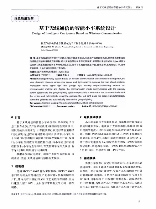
uses ultrasonic distance sensor.color sensor and light sensor to perceive the road ahead obstacle,
intersection trafic signal light and garage light intensity respectively Using external red
3 循 迹 模 块
1 控 制 器
选用 STC12C5A60S2作 为主控制器。srl、Cl2C5A60S2 系 列 片机 是宏 晶科 技生 产 的单时钟 /机器 周期 的单 片机 ,片 内具有 大容量 FLASH 艺 的程序存 储器 ,且运 行 速度 儿倍于 805l,是 目前非 常具有竞 争力 的一种控 制 器 。
根据 系统 的设计 要求 ,将整个 系统 分为控制器 、电 机驱动 、循迹 、无线通信 和传 感器五大模块 。
小 年的 轮 由直流 电机驱动 ,m单 片机控 制直流电 机的转速和 力‘向。电机属 于大功率器件 ,单片机 I/0端 ¨提供 的电流不足以驱动电机转动 ,故必须外接驱 动电 路 。选J}}j L298N驱动直流 电机转动 。I298N T作时电压 最 高可 以达到 46V,其输 电流 的峰 值 町以达到 3A,正 常 l 作u,j-n-  ̄电流 为 2A,额定功率 为 25W,L298N常用 来 驱 动电机 、继 电器等 负载 。L298N电机驱动模块需 占用 6位 l/()端 ¨,用单 片机 PO.1一PO.5控制 。
Key w ords:ultrasonic ranging: nfrared com m unication;Zigbee com m unication
wifi智能小车毕业设计
wifi智能小车毕业设计wifi智能小车毕业设计随着科技的不断发展,智能化已经成为了现代社会的一个重要趋势。
在这个背景下,智能小车作为一种应用广泛的智能设备,正受到越来越多人的关注。
本文将介绍一个基于wifi技术的智能小车毕业设计,探讨其设计原理、功能特点以及未来的发展前景。
一、设计原理该智能小车的设计基于wifi技术,通过无线网络连接实现与用户的交互和控制。
整个系统主要由三个部分组成:智能小车、控制端和服务器。
智能小车是整个系统的核心部分,它搭载了各种传感器和执行器,可以感知环境并执行相应的动作。
通过wifi模块,智能小车可以与控制端进行通信,接收控制指令并发送传感器数据。
控制端是用户与智能小车进行交互的工具,可以是电脑、手机或者平板等设备。
用户可以通过控制端发送指令给智能小车,控制它的运动、转向以及其他功能。
服务器是整个系统的中枢,负责接收用户发送的指令并将其转发给智能小车。
同时,服务器也负责接收智能小车发送的传感器数据,并将其展示给用户。
二、功能特点1. 远程控制:用户可以通过控制端远程控制智能小车的运动和转向。
无论用户身处何地,只要有网络连接,就可以实现对智能小车的控制。
2. 自动避障:智能小车搭载了红外传感器和超声波传感器,可以感知前方的障碍物,并自动避开。
这样可以保证智能小车在运行过程中不会碰撞到障碍物。
3. 视频监控:智能小车还搭载了摄像头,可以实时传输视频到控制端。
用户可以通过控制端观察智能小车周围的环境,实现远程监控的功能。
4. 数据记录与分析:智能小车可以将传感器数据发送到服务器,服务器将这些数据保存下来并进行分析。
用户可以通过控制端查看历史数据,并对数据进行分析和处理。
三、未来发展前景随着物联网技术的不断发展,智能小车的应用前景将会更加广阔。
未来,智能小车可以与其他智能设备进行联动,实现更多的功能。
例如,智能小车可以与智能家居设备进行连接,实现智能家居的控制和管理。
用户可以通过控制端一键控制家中的灯光、电器等设备,实现智能化的生活方式。
基于无线传输的智能巡航小车的设计
. .. . 毕业设计说明书英文文献及中文翻译学生:璐学号:0805054117学院:信息与通信工程学院专业:自动化指导教师:贾建芳2012年6月Obstacle Avoiding Real-Time Trajectory Generation and Control ofOmnidirectional VehiclesJi-wung Choi, Renwick E. Curry and Gabriel Hugh ElkaimAbstractIn this paper, a computationally effective,trajectory generation algorithm of omnidirectional mobile robots is proposed. The algorithm plans a reference path based on B′ezier curves, which meet obstacle avoi dance criteria. Then the algorithm solves the problem of motion planning for the robot to track the path in a short travel time while satisfying dynamic constraints and robustness to noise. Accelerations of the robot are computed such that they satisfy the time optimal condition for each sample time interval. The numerical simulation demonstrates the improvement of trajectory generation in terms of travel time, satisfaction of dynamic constraints and smooth motion control compared to previous research.I. INTRODUCTIONMany researchers have worked on vehicle motion planning. The form of the vehicle includes car-like, differential drive, omni-directional, and other models. Balkcom [3] developed the time optimal trajectories for the bounded velocity model of differential drive robots. Jung [4] and Moore [5] dealt with omnidirectional vehicles; the control strategy employed by these papers consists of building a geometric path and tracking the path by using feedback control. Huang [6] proposed an approach to vision-guided localnavigation for nonhlo nomic robot based upon a model of human navigation. The approach uses the relative headings to the goal and to obstacles, the distance to the goal, and the angular width of obstacles, to compute a potential field. The potential field controls the angular acceleration of the robot, steering it toward the goal and away from obstacles. Hamner [7] maneuvered an outdoor mobile robot that learns to avoid collisions by observing a human driver operate a vehicle equipped with sensors that continuously produce a map of the local environment. The paper describes implementation of steering control that models human behavior in trying to avoid obstacles while trying to follow a desired path. Hwang [8] developed the trajectory tracking and obstacle avoidance of a car-like mobile robot within an intelligent space via mixed H2=H¥decentralized control. Two CCD cameras are used to realize the position of the robot and the position of the obstacle. A reference command for the proposed controller of the robot is planned based on the information from these cameras.J. Choi is a Ph.D. candidate in Computer Engineering Department at the University of California, Santa Cruz, 95064, R. Curry is an Adjunct Professor in Computer Engineering Department at the University of California, Santa Cruz, 95064, G. Elkaim is an assistant professor in Computer Engineering Department at the University of California, Santa Cruz Santa Cruz, 95064, USA. This paper focuses on two papers: Kalmar-Nagy [2] and Sahraei [1]. Kalmar-Nagy [2] has proposed a minimum time trajectory generation algorithm for omnidirectional vehicles, that meets dynamic constraints, but no obstacles are considered. A near-optimal control strategy is shown to be piecewise constant (bang-bang type) in the paper. Sahraei [1] has presented a motion planning algorithm for omnidirectional vehicles, based on the result of [2]. The paper has claimed that the algorithm satisfies obstacle avoidance as well as time optimality given in discrete time system.The paper shows that Sahraei’s algorithm is problematic. To resolve the problems, a new motion planning algorithm for omnidirectional vehicles is proposed, which also satisfies obstacle avoidance and dynamic constraints in a discrete time system. The numerical simulations provided in this paper demonstrate a better solution to the problem of motion planning by the proposed algorithm than Sahraei’s. The paper is organized as follows. Section II describes dynamic constraints of the robots based on the result of [2]. In section III, Sahraei’s algorithm [1] is introduced. Section IV proposes the new algorithm. Finally, a numerical simulation is presented in Section V.II. DYNAMIC CONSTRAINTS OF THE OMNIDIRECTIONAL VEHICLE Fig. 1(a) shows the bottom view of an omnidirectional vehicle that consists of three wheels. This type of vehicle is able to move in any direction and spin as it moves. Kalmar-Nagy described a model that relates the amount of torque available for acceleration to the speed of the three wheeledomnidirectional vehicle [1]. This section is based on the results of [2].(a) Bottom view [2] (b) Geometry [2]Fig. 1. The omnidirectional vehicleIt is shown that the drive velocities are defined as linear functions of the velocity and the angular velocity of the robot:()1)3cos()3sin()3cos()3sin(cossin...321⎥⎥⎥⎥⎥⎦⎤⎢⎢⎢⎢⎢⎣⎡⎥⎥⎥⎥⎥⎥⎦⎤⎢⎢⎢⎢⎢⎢⎣⎡+-+------=⎥⎥⎥⎦⎤⎢⎢⎢⎣⎡θθπθπθπθπθθyxLLLvvvwhere L is the distance of the drive units from the center of mass of the robot, vi are the individual wheel velocities, q is the angle of counterclockwise rotation (See Fig. 1(b)). New time and length scales are introduced:()294,322maxβαβmUmT=ψ=to normalize x, y, and t to the nondimensional variablesTttyyxx=ψ=ψ=,,(3)The constants a and b are determined by the motor character. Umax is themaximum value of the voltage applied to the motor, and m is the mass of the robot. Then the constraint of the robot (after dropping the bars) becomes()()122≤+t q t q y x (4)(see [2] for the full derivation), where the two components of control qx(t) and qy(t) are()()()()6.5,y y t q x xt q y x +=+=It has been shown that the time-optimal control strategy is achieved when()()[])7(,0,122f y x t t t q t q ∈=+where t f is the final time. Kalmar-Nagy [2] solves the problem of time-optimal motion trajectory by ensuring the equality, but no obstacles are considered.III. SAHRAEI’S ALGORITHMSahraei [1] proposed a trajectory generation algorithm based on the results of [2]. The algorithm is differentiated from Kalmar-Nagy’s algorithm by two properties: real-time trajectory generation and obstacle avoidance. The first step is to construct the Voronoi diagram to find a path that avoids obstacles. Voronoi diagram is the partitioning of a plane with n points into n cells. The partitioning is made such that each cell includes one point and every point in a given cell is closer to the captured point. After constructing the Voronoi diagram, the start and target points, s and t are added to it with corresponding edges which connect these two points to their cell vertices.Then Dijkstra’s shortest path algorithm is run. The resulting path is the shortest path whose edges are in the Voronoi diagram. Two B′ezier curves are used to find a smooth path near the resulting path with regards to initial and final conditions. A B′ezier Curve of degree n is represented by n+1 control()()[]()()()()9}.,1,0{,181,0,0n i i n B P B P i i n n i i n i n i ∈-⎪⎪⎭⎫ ⎝⎛=∈=-=∑λλλλλλ The curve passes through P0 and Pn and is tangent to P0P1 and Pn 1Pn. Also, it lies within the convex hull of control points. Let p0; p1; : : : ; pn denote the vertices of the shortest path and p0, and pn denote s and t, respectively. The first B´ezier curve, Pa(l) for l 2 [0;1], is constructed by p0, q, r, and p1, where control points q and r are introduced to satisfy slope of initial velocity constraint and continuity ofcurve and its slope in p1. The second B´ezier curve Pb(l) is constructed by n P P 1 Following equations describe boundary conditions:()()()()()()0011,0000b b a a a a P P P P v v P P == (10)Fig. 2 shows an example of the paths.Fig. 2. A smooth path resulted from two Bezier curves. The first Bezier curve isillustrated in green and the second one is shown in blue [1].Finally Sahraei assigned a velocity magnitude to each point on the generated curve ()()()()λλλY X P ,= .to implement this, the paper tried to find a function α {}[]1,0,2,,0∈→∈λ h h t [0;1] such that X(a(t)) and Y(a(t)) satisfy the following dynamic constraint()(),122≤+++Y Y X X (11)where h 2 R+ is the sample time interval. Note that the variables X, Y, and t for (11) are normalized values by (2). For the sake of optimality a(t) was calculated such that the left side of the inequality constraint (11) approaches1. To find ln , a(nh) for all n’s Sahraei used derivative approximations to define the function f :()()()()()()()()()()()ελλλλλλλλλλλ+-⎪⎭⎫ ⎝⎛-++-+⎪⎭⎫ ⎝⎛-++-=------122222212222122h Y Y Y h Y Y h X X X h X X f n n n n n n (12)ln is calculated by solving the equation()0=λf (13)based on ln 1 and ln 2 by Newton’s method. e 2 R+ in (12) guarantees that the result of Newton’s method makes the left side of inequality (11) less than but close to 1. Since ln relies on two previous values of l, at the first step l0 and l1 should be calculated. It is straightforward that l0 = 0. To calculate l1, a hypothetical l 1 is introduced to approximate the position of the robot before initial time, X(l 1) defined by()()010x v h X X ≈--λλ (14)and so forth for Y. One of major drawbacks of this approach is the fact that there is no guarantee of existence of ln for all n’s to satisfy (13) with small enough value of error, j f (l)j. That is mainlybecause X(l) and Y(l) are constrained by the polynomial of P(l). This drawback will result in a violation of dynamic constraint of (4).IV. PROPOSED ALGORITHMThis section proposes a new algorithm for obstacle avoiding real-time trajectory generation of omnidirectional vehicles. To describe this method, let an = (axn ;ayn ), vn = (vxn ;vyn ), zn = (xn;yn) denote the acceleration, velocity, and position of the vehicle, respectively, at sample time nh. All of the variables used in this section are nondimensional variables scaled by (2). The new algorithm uses a Voronoi’s diagram and a B′ezier curve to gen erate the reference trajectory as Sahraei did. A problem of Sahraei’s algorithm is that it did not do any calculation to ensure that the B′ezier curves miss the obstacles. To resolve this problem, this paper ensures that the convex hull constructed by the control points of the B′ezier curve do not contain any obstacles. The algorithm also deals with velocities and accelerations of the robot in a discrete time system sampled at t = f0;h;2h; : : :g. However, it computes accelerations an that meet optimal condition (7) as opposed to that Sahraei computes positions zn. The set of all such accelerations An isrepresented as()()()}.1,{22=+++=ℜn n n n n n y y x x y x n v a v a a a (15)If vn is given, (15) can be rewritten as()[]}2,0sin ,cos {πθθθ∈+-+-=ℜn n y n x n n n v v (16)The beauty of (16) is that it guarantee s satisfaction of (7) while Sahraei’s algorithm only has the left side of the equation approaching 1. It also simplifies the value of the accelerations to one variable qn. Geometrically, An is the circle that has center at ( vxn ; vyn ) and radius of 1. In this algorithm, the robot is assumed to follow the constant acceleration equations of motion with an for time interval t 2. Once an is determined, the velocity and the position at next sample time are calculated by applying the constant acceleration equations with an:()()18,217,,211n n n n n n n n n n n a a h hv z z a ha v v ℜ∈++=ℜ∈+=++In the problems that we consider, v0 and z0 are initially given. So a0 is solely determined by selecting q0 in (16). Once a0 is determined, v1 and z1 are obtained by applying (17) and (18) and using a0, and so on. Thus we only need to find qn for all n’s in order to fulfill motion planning of the robot, represented by a set of zn. We also can generalize that vn and zn are give when we calculate qn at t = nh.Equation (18) can be rewritten as the sum of two vectors:,111++++=n n n r c z (19)Where()()21.sincos220,22121⎥⎦⎤⎢⎣⎡=⎥⎥⎦⎤⎢⎢⎣⎡⎪⎪⎭⎫⎝⎛-+⎥⎦⎤⎢⎣⎡=++nnnyxnnnhrvvhhyxcnnθθSince vn and zn are given at t = nh,+1 is known, while rn+1 depends on qn. So the set of all zn+1 corresponding to1+ℑn is given by}2{21111hczznnnn=-=ℑ++++(22)Geometrically, Zn+1 can be interpreted as the circle that has center at+1 and radius of h22 as shown in Fig 3(a). The intersections of Zn+1 and the pre-generated B´ezier curve P(l) satisfy the optimal condition (7). We will select zn+1, the intersection further from current position since thatprovides a shorter travel time (See Fig. 3(a)).(a)Zn+1 on a reference trajectory. (b)The enlarged Zn+1. Fig. 3. Geometry of Zn+1 from zn on a reference trajectory.p is defined by the point on the reference trajectory, which is the closest to 1+nc In reality, the acceleration cannot be constant over the sample interval because the dynamic constraint (4) operates at all times. That is, even thoughan 2 An guarantees satisfaction of the optimal condition (7) at t = nh, the velocity changes due to an over the sample interval t 2 will violate the dynamic constraint. To resolve this problem, we provide the closed-form analytical solution that obeys .the dynamic constraints at all times as follows. The constraint operating at t ()()h n nh t 1,+∈:()()()()()()()24,23,t dt dz t v A t v t dtdv t a =+-==Where: [].sin cos Tn n A θθ= (25) Assuming qn is constant over the sample interval t 2, the velocity and position can be found in closed form ()()h n nh t 1,+∈ the velocity and position can be found in closed form:()()()()()()()()2711261A e t v e z t z Ae v e t v t n t n t n t ------+-+=-+=A second order Taylor series is used for small time intervals, h, yielding an expression for the position at the end of the sample interval(),2222A h h h v h h z h nh z n n ⎪⎪⎭⎫ ⎝⎛⎪⎪⎭⎫ ⎝⎛--+⎪⎪⎭⎫ ⎝⎛-+=+(28) which is the exact same equation as the expression of zn+1 2 Zn+1 in (22). That is, the exact closed-form solution is the same, to second order, as the assumption of constant acceleration. Assuming that the reference path is planned such that Zn+1 intersects the path for all n’s, we only need to find qncorresponding to z n+1 for motion planning of the vehicle. However, noise in a real system and large parh curvatures may cause Zn+1 to miss the path. For this case, another path following heuristic is required. The algorithm is divided into two modes depending on whether Zn+1intersects the reference path or not: intersect-reference-trajectory (IR) and out-of-reference-trajectory (OR).A. IR modeIn IR mode, qn corresponding to z_n+1 is calculated in computationally efficient way. Firstly, we define the point on the B´ezier curve, p which is the closest to+1 as shown in Fig. 3(a). To calculate p, we introduce the function f :()()()()()[]1,0,2211∈-+-=++λλλλn n y x c Y c X f (29)Let l p denote the parameter that minimizes f (l):[]().min arg 1,0λλλf p ∈= (30)l p is computed by the steepest descent or Newton algorithms using the backtracking line search. Then p is given by()()().,λλY X p p = (31) In Fig. 3(a), the portion of the B´ezier curve inside of the circle Zn+1 can be considered to be line segment of which the slope is the slope of tangent at p, given that time interval h is small enough. So we can approximate z_ n+1 as the intersection point between the circle and the straight line segment. Let f denote the slope of the tangent line:()().tan 1⎪⎪⎭⎫ ⎝⎛=-p p X Y λλφ (32)Looking at the geometry of p ,*1+n z and 1+n c ,n θ is given by :ζφθ+=n (33)where ζ can be calculated by applying law of sines for1*1++∆n n pc z : ().sin 2sin 211⎪⎪⎭⎫ ⎝⎛+--=+-φγπζh c p n (34) and g is the signed angle of direction of the vector c n 1+B. OR modeTo account for noise present in a real system, an efficient path following heuristic is presented. To describe this method, we introduce two terms: yerr and yerr. yerr is defined by the distance between+1 and p. yerr is defined by the angle difference from the current heading of the robot, yn to the slope of tangent at p (See Fig. 3(a)). The feedback control is designed such that the robot approaches the reference trajectory while making yerr small. So we use a PID steering control given bydt y k k y k err i err d err p ⎰++=ψδψ (35)where δψ is the deflection of the heading of the robot:n n ψψδψ-=+1 (36) The angle n v h 1-of the acceleration 11+n v h that produces the desired dy can be calculated in cost efficient way. Fig. 4 shows the relationship of 11+n v h andn v h 1- in acceleration frame. From (16), An is the circle that has center at max δψand radius of 1. Rewriting (17), the acceleration can be representedas the sum of two vectors:()⎪⎪⎩⎪⎪⎨⎧≤⎪⎭⎫⎝⎛->⎪⎭⎫⎝⎛-⎪⎪⎭⎫⎝⎛-=-111,111,111sin1maxnnnvhifvhifvhπδψ(38)Fig. 4. Geometry of nna,θIn Fig. 4, nna,θcan be represented as:,1φδψψφψθ++=+=+nnn(39)where f can be obtained by using law of sines:().sin11sin1⎪⎪⎭⎫⎝⎛⎪⎭⎫⎝⎛-=-δψφnvh(40)Note that dy is a signed angle and so f is determined by dy. Equation (35) can be written as (41) by using (38), (39),and (40)dtykkykerrierrderrpnn⎰++++=ψφψθ(41)maxmaxδψφψθδψφψ++≤≤-+nnn(42) In order to satisfy obstacle avoidance, the maximum yerr should be lessthan the minimum distance from obstacles to the pre-generated B´ezier curve. For computational efficiency, the minimum distance is measured as minimum distance from obstacles to control points of the B´ezier curve.V. NUMERICAL SIMULATIONSSimulations provided in this section demonstrate improvement of trajectory generation and control by the proposed algorithm in terms of travel time, satisfaction of the dynamic constraint, and smooth motion control compared to Sahraei’s algorithm. Also, they show robustness o f the proposed algorithm. Fig. 5 shows the course used for the simulation. Red circles indicate obstacles. The initial and final conditions are given by:()[]()()[]()()[]()45.28.3,85.644,0,043,54.0,75.100m z s m v m z f ===The sample time interval h is given by:[][][][].3,1,1,1max v U kg m s kg V N ====βα(47)Fig. 5. The resulting trajectories by different algorithms over the reference trajectory (bold black curve).The reference trajectory is constructed by a B´ezier curve for which the control points are()()()()()(),28.3,85.6,24.3,35.5,04.2,55.4,14.2,72.3,05.2,49.3,54.0,75.1543210======p p p p p p (48)and illustrated as bold b lack curve in Fig. 5. The simulation of Sahraei’s algorithm has been done with the same parameters above and e = 0:01. In Fig. 5, two kinds of trajectories are generated depending on addition of noise. The open loop trajectory without noise is generated by applying two different algorithms: the proposed algorithm and Sahraei’s algorithm. The closed loop trajectory with noise is generated by the proposed algorithm. The reference trajectory is generated smooth enough thatZn+1 contains a portion of the trajec tory for all n’s. So, in simulation of the proposed algorithm, only IR logic is used for the open loop trajectory while combination of IR and OR is used for the closed loop trajectory. The resulting closed loop trajectory shows the robustness to noise in Fig. 5. The noise was modeled as white noise with magnitude of 0:05m and added to actual position. The simulation results are listed in table I. The resulting final times t f by the proposed algorithm are substantially shorter than the one by Sahraei’s algorithm. In the table, the cross track error cerr is defined as the distance of the line normal to the path and passing through the vehicle position. Sahraei’s algorithmleads to violation of the dynamic constraint (4). We can see that q2x +q2y exceeds boundary condition 1 in Fig. 6(f). On the other hand, q2x +q2y by the proposed algorithm is 1 at every sample time interval as shown in Fig. 6(d) and6(e). In addition, the proposed algorithm generates smoother controls qx and qy and velocities vx and vy than S ahraei’s algorithm as shown in Fig. 6(a), 6(b), 6(g) and 6(h).VI. CONCLUSIONSThis paper proposes a collision-free real-time motion planning algorithm for an omnidirectional mobile robot. It has been shown that planned motion of the robot is a computationally effective way to satisfy obstacle avoidance as well as robustness, and the proposed algorithm leads toshort travel times. Numerical simulations demonstrate the improvement of the motion planning compared to Sahraei’s algorithm.(a) qx and qy by IR. (b) qx and qy by IR and OR (noise). (c) qx and qy by Sahraei.(d) q2x+q2yby IR. (e) q2x+q2y by IR and OR (noise). (f) q2x+q2yby Sahraei..(g) vx and vy by IR (h) vx and vy by IR and OR (noise).(i)vx and vy by Sahraei.Fig. 6. The results obtained by the proposed algorithm and Sahraei’s algorithm.TABLE IRESULTS OF THE SIMULATIONMethods t f [s] Violation of (4)[%]dtc f terr 0IR without noise 3:6667 0 0IR and OR withnoise3:4667 0 0.0018Sahraei withoutnoise13:2667 31.91 0REFERENCES[1] A. Sahraei, M. T. Manzuri, M. R. Razvan, M. Tajfard and S. Khoshbakht,“Real-Time Trajectory Generation for Mobile Robots,” The 10th Congress of the Italian Association for Artificial Intelligence (AIIA 2007) September 10-13, 2007 .[2] Kalmar-Nagy T., D’Andrea R., Ganguly P., “Near-optimal dynamic trajectory generation and control of an omnidirectional vehicle,” Robotics and Autonomous Systems, Volume 46, Number 1, 31 January 2004 , pp. 47-64(18), Elsevier.[3] Balkcom, D. and Mason, M. Time Optimal, “Trajectories for Bounded Velocity Differential Drive Robots,” IEEE International Conference on Robotics and Automation (ICRA 00), p. 2499 - 2504,2000.[4] Jung, M., Shim, H.,Kim,H.and Kim, J. “The Miniature Omnidirectional Mobile Robot OmniKity-I (OK-I),” International Conference on Robotics and Automation, p. 2686-2691, 1999.[5] Moore,K.L. and Flann,N.S.,“Hierarchial Task Decomposition Approach to Path.Planning.and.Control.for.an.Omni-Directional.AutonomousMobileRobot,”InternationalSymposium.on.IntelligentControl/Intelligent.Systems.and.Semiot ics,p.302-307, 1999.[6] Huang, W. H., Fajen, B. R., Fink, J. R., Warren, W. H., “Visual navigation and obstacle avoidance using a ste ering potential function,” Robotics and Autonomous Systems, vol. 54, Issue 4, p. 288-299, 28 April 2006.[7] Hamner, B., Singh, S., Scherer, Se., “Learning Obstacle Avoidance Parameters from Operator Behavior,” Special Issue on Machine Learning Based Robotics in Unstructured Environments, Journal of Field Robotics, vol. 23, 11/12, p. 1037-1058, December 2006.[8] Hwang, C., Chang, L. “Trajectory Tracking and Obstacle Avoidance of Car-Like Mobile Robots in an Intelligent Space Using Mixed H2=H ¥Decentraliz ed Control,” Mechatronics,IEEE/ASMETransactionson,vol.12,Issue3,p.345-352.june2007.车辆的实时壁障控制和轨迹生成Ji-wung Choi ,Renwick E. Curry 和加布里埃尔·休Elkaim摘 要本文提出了一种计算有效的轨迹全方位移动机器人的生成算法建议。
基于无线通信技术的多功能智能小车视频传输系统方案
基于无线通信技术的多功能智能小车视频传输系统方案一、引言随着无线通信技术的发展,智能小车逐渐成为人们生活中的一个重要角色。
为了实现对智能小车的远程控制和监控,需要建立一个可靠的视频传输系统。
本文将提出一种基于无线通信技术的多功能智能小车视频传输系统方案,以满足用户的远程控制和监控需求。
二、系统框架本系统由发送端和接收端组成。
发送端装载摄像头,并通过无线通信模块将视频信号传输到接收端。
接收端接收视频信号,并通过显示器显示实时视频画面,同时向发送端发送控制指令。
三、硬件设计1.发送端:发送端主要由以下硬件组成:-摄像头:负责拍摄视频信号。
-无线通信模块:如Wi-Fi模块或蓝牙模块,负责视频信号的传输。
-控制模块:负责接收来自接收端的控制指令。
2.接收端:接收端主要由以下硬件组成:-无线通信模块:与发送端相对应的无线通信模块,负责接收视频信号。
-显示器:负责显示接收到的视频信号。
-控制模块:负责向发送端发送控制指令。
四、软件设计1.发送端:发送端软件主要包括以下功能:-视频采集:通过摄像头采集视频信号。
-视频编码:对采集到的视频信号进行编码压缩,以减少数据传输量。
-数据传输:通过无线通信模块将编码后的视频信号传输到接收端。
-控制指令接收:接收来自接收端的控制指令,并按照指令对智能小车进行远程控制。
2.接收端:接收端软件主要包括以下功能:-数据接收:通过无线通信模块接收发送端传输过来的视频信号。
-视频解码:对接收到的视频信号进行解码还原,以得到原始的视频信号。
-实时显示:将解码后的视频信号通过显示器实时显示。
-控制指令发送:向发送端发送控制指令,以实现对智能小车的远程控制。
五、系统优势1.方便易用:用户可以通过接收端实时看到智能小车行驶的画面,并通过控制指令实现对智能小车的远程控制。
2.实时性高:通过视频编码和解码技术,视频传输的延迟可以降低到较低水平,使用户能够准确地实时监控智能小车的状况。
3.灵活多样:用户可以根据实际需求选择不同的无线通信模块(如Wi-Fi或蓝牙),以适应不同的传输距离和传输速率。
WiFi智能小车设计论文

WiFi智能小车设计论文目录1设计理念与背景 (1)1.1 当代智能汽车的发展 (1)1.2 设计的理念与目的 (2)2设计方案的论证及选择 (2)2.1 总体设计系统图 (2)2.2 主控系统 (3)2.3 电源模块 (4)2.4 电机驱动模块 (4)2.4.1 电机模块选择与论证 (4)2.4.2 电机驱动模块选择与论证 (5)2.5 显示模块 (6)2.6 避障模块 (6)2.7 路由器模块 (7)2.7.1 wifi芯片原理图 (8)2.7.2 摄像头 (9)3 硬件电路的设计 (9)3.1 总体设计 (9)3.2 驱动电路 (10)3.2.1 电机驱动模块的使用 (10)3.2.2 电机驱动的原理 (11)3.3 显示电路 (13)3.4 单片机最小系统的设计 (14)3.4.1 主控芯片的介绍 (14)3.4.2 单片机最小系统 (15)4 程序调试 (15)4.1 调试软件 (15)5 设计小结 (16)附录1 电路原理图 (18)附录2 源程序 (20)附录3 实物照片 (32)1设计理念与背景1.1 当代智能汽车的发展现在是一个智能化的时代,各种智能化设备正在逐步替代人为的操作。
随着汽车工业的迅速发展,关于智能汽车的研究也就越来越受人关注。
全国电子大赛和省内电子大赛几乎每次都有智能小车这方面的题目,全国各高校也都很重视该题目的研究。
对于智能汽车的研究,国内外都有很大的成就,谷歌的无人驾驶汽车,已经能够在高速公路上安全行驶数千公里,在高速行驶下都能有这么好的操控能力,无非是智能汽车领域的一座里程碑。
对于智能泊车系统,现在也已经进入了民用领域,很多车型也装配了该系统,有了他,汽车用超声波传感器扫描路面两侧,通过比较停车的空间和车辆的长度,自动寻找合适的停车位。
找到合适位置后,驾驶者只需控制刹车,车辆自动控制转向操作,即可将车停进停车位,并且液晶屏会有相应的显示。
对于这样现代如此强大的科技手段,无线智能已经不再是幻想,是人们想要达到的一种高度了。
- 1、下载文档前请自行甄别文档内容的完整性,平台不提供额外的编辑、内容补充、找答案等附加服务。
- 2、"仅部分预览"的文档,不可在线预览部分如存在完整性等问题,可反馈申请退款(可完整预览的文档不适用该条件!)。
- 3、如文档侵犯您的权益,请联系客服反馈,我们会尽快为您处理(人工客服工作时间:9:00-18:30)。
中北大学
毕业设计开题报告
学生姓名:李璐学号:********** 学院、系:信息与通信工程学院电气工程系专业:自动化
设计题目:基于无线传输的智能巡航小车的设计
****:***
2012年3月15日
毕业设计开题报告
1.结合毕业设计情况,根据所查阅的文献资料,撰写2000字左右的文献综述:
文献综述
一、研究背景及意义
智能小车,又称轮式机器人。
机器人的应用越来越广泛,几乎渗透到所有领域。
机器人的发展体现了一个国家技术水平的高低,现代机器人从其诞生到现在,己经发展到了第三代。
第一代机器人是示教再现型机器人。
它们装有记忆存储器,由人将作业的各种操作要求示范给机器人,使之记住操作的程序和要领。
当它接到再现命令时,则自主地再现示教的动作。
第二代机器人是装有小型计算机和简单传感器的离线编程的工业机器人。
它能感知外界信息和进行“思维”,比第一代机器人更灵活、更能适应环境变化的需要。
第三代是智能机器人。
智能机器人是“具有感知、思维和动作的机器”。
它装有多种传感器,能识别作业环境,能自主决策,具有人类大脑的部分功能,且动作灵活,是人工智能技术发展到高级阶段的产物[1]。
近些年中国航天事业飞速发展,是不折不扣的航天年,随着实现载人上天以及太空行走,中国在世界的航空领域也有了一席之地。
而对于地外星球的研究,智能小车也发挥着它极大的作用,可以完成星球表面岩石采集等任务,从而代替人类完成一些比较危险的工作。
智能车是一个集环境感知、规划决策等功能于一体的综合系统。
它在各个领域都具有广泛的应用前景[2]。
与智能小车密切相关的就是无线传输技术,随着集成电路技术和计算机技术的成熟,无线通信技术向高速率、大容量、小型化的无线多媒体通信方向发展,使得各种短距离无线通信(Short-range Wireless Communications)应用不断涌现,并得到了广泛的研究和使用。
蓝牙 V3.0、ZigBee、微波RFID(Radio Freqency Identification)以及60 GHz毫米波个域通信(Millimeter- wave WPAN)技术等新一代短距离无线通信应用的出现,显示出短距离无线通信技术强大的生命力和广阔的应用前景[3]。
2.本课题要研究或解决的问题和拟采用的研究手段(途径):
一、本课题要研究或解决的问题
1、熟悉短距离无线通讯的工作原理;
2、熟悉单片机的相关理论;
3、理解无线射频识别技术的基本原理和相关方法;
4、进行基于无线传输的智能巡航小车的设计。
二、拟采用的研究手段
针对研究问题,先从图书馆以及网络中查询、搜集相关资料,尽可能的做到细致、全面,把一些可能发生的情况考虑到。
然后,对大量文献进行分析,找到最优的方案来实行,了解当前本课题的最新研究成果以及尚未解决的难题,以免自己绕弯路。
另外还需要多向指导老师和同学们咨询,有问题当天解决。
指导教师意见:
李璐同学通过查阅书籍,收集资料,对智能车的系统设计有了初步认识,了解了无线传输的理论知识,提出用无线射频技术设计,构建了整体结构,此方法具有一定的可行性。
同意开题
指导教师:
年月日
所在系审查意见:
同意开题
系主任:
年月日。
