电液伺服控制器使用说明书
吉仕科伺服驱动器js580说明书

吉仕科伺服驱动器js580说明书
品牌:吉仕科
型号:JS580
功能:功率伺服驱动
元件类型:机电
控制方式:闭环
功率:15kw
额定电压:380V
加工定制:是
JS580电液伺服驱动器内置高性能油压PID控制算法,实现更快、更稳、更准的液压控制体验;采用高可靠性的CAN通讯,方便实现单机多泵并联、合流分流控制;电机温度KTY,PTC检测可选,实时检测温度准确保护。
可提供多制式电压选择;可实现液压伺服应用中的精密压力、流量和位置控制简单调试方法,多种保护功能使系统得到高稳定性和高耐用性。
应用范围:注塑机、压铸机、锻压机、塑胶挤出机、金属挤出机、四柱油压机、吹瓶机、打包机、鞋机、线材机械等。
伍德沃德 PG-EG 执行器 电液伺服执行器,用于发动机控制说明书
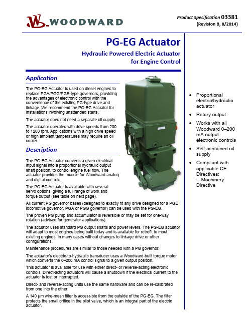
Product Specification 03381(RevisionB, 8/2014)PG‐EG ActuatorHydraulic Powered Electric Actuatorfor Engine ControlApplicationThe PG-EG Actuator is used on diesel engines toreplace PGA/PGG/PGE-type governors, providingthe advantages of electronic control with theconvenience of the existing PG-type drive andlinkage. We recommend the PG-EG Actuator forinstallations involving unattended starts.The actuator does not need a separate oil supply.The actuator operates with drive speeds from 200to 1200 rpm. Applications with a high drive speedor high ambient temperatures may require an oilcooler.DescriptionThe PG-EG Actuator converts a given electricalinput signal into a proportional hydraulic outputshaft position, to control engine fuel flow. Theactuator provides the muscle for Woodward analogand digital controls.The PG-EG Actuator is available with severalservo options, giving a full range of work andtorque output (see table on next page).All current PG governor bases (designed to exactly fit any drive designed for a PGElocomotive governor, PGA or PGG governor) can be used with the PG-EG.The proven PG pump and accumulator is reversible or may be set for one-wayrotation (advised for generator applications).The actuator uses standard PG output shafts and power levers. The PG-EG actuatorwill adapt to most engines being built today and is available for retrofit to mostexisting engines, in many cases without changes to linkage drive or otherconfigurations.Maintenance procedures are similar to those needed with a PG governor.The actuator's electric-to-hydraulic transducer uses a Woodward-built torque motorwhich converts the 0–200 mA control signal to a given output position.This actuator is available for use with either direct- or reverse-acting electroniccontrols. Direct-acting actuators will cause a shutdown if the electrical current to theactuator is lost or interrupted.Direct- and reverse-acting units use the same hardware and can be re-calibratedfrom one into the other.A 140 μm wire-mesh filter is accessible from the outside of the PG-EG. The filterprotects the small orifice in the pilot valve, which is an integral part of the electricactuator.∙ Proportionalelectric/hydraulicactuator∙ Rotary output∙Works with allWoodward 0–200mA outputelectronic controls∙ Self-contained oilsupply∙ Compliant withapplicable CEDirectives:—MachineryDirectiveSpecificationsControl QualitiesHysteresis Within 3% of maximum travel when measured over full travel. Within 0.5% ofmaximum travel when measured over 4% of full travel at 0.1 Hz.Temperature Drift Nominally ±1 degree per 38 °C (100 °F)Time Constant 65 to 85 ms for ±50 mA step with 1379 kPa (200 psi) actuator oil pressure and80 SUS viscosity oilLinearity Within 2.5% of full travelType 12 29 58 200 300 500Sump Capacity 1.4 liters1.5 qt US1.4 liters1.5 qt US1.4 liters1.5 qt US6.2 liters6.5 qt US6.2 liters6.5 qt US6.6 liters7.0 qt USMaximum Work Output16 J12 ft-lb39 J29 ft-lb79 J58 ft-lb237 J175 ft-lb422 J311 ft-lb648 J478 ft-lbRotary Travel 30° 30° 30° 42° 42° 42° Serrated OutputShaft Dimension0.750-48 1.000-48 1.000-48 1.125-48 1.500-60 1.500-60Weight 39–54 kg85–120 lb39–54 kg85–120 lb39–54 kg85–120 lb159 kg350 lb159 kg350 lb227 kg500 lbMaximum DriveSpeed Range200–1200 rpm 200–1200 rpm 200–1200 rpm 200–1200 rpm 200–1200 rpm 200–1200 rpm Recommended DriveSpeed250–1000 rpm 250–1000 rpm 250–1000 rpm 400–1000 rpm 400–1000 rpm 400–1000 rpmInternal Hydraulic Pressure 690 kPa100 psi690 kPa100 psi1724 kPa250 psi1379 kPa200 psi2482 kPa360 psi1931 kPa280 psiAll standard PG bases are available for PG-EG 12, 29, and 58 (see manual 36693, PG Base Assemblies).Construction Base and power block are cast iron. Column is aluminum. Internal parts are case-hardened steel.Vibration Resistance Random: 0.01 G²/Hz at 10 Hz, 0.1 G²/Hz at 100 Hz, 0.1 G²/Hz at 1000 Hz,0.05 G²/Hz at 2000 Hz (12.8 Grms); 3 hours per axis.Woodward advises that PG-EG actuators be equipped with an oil spray to minimizethe effects of vibration.Header Optional FeaturesBooster Servomotor A booster servomotor may be used with the PG-EG to help the prime mover startquickly by moving the actuator output toward the maximum-fuel position at start-up. Governor Heat Exchanger A remote heat exchanger may be required to lower governor oil temperatures inapplications where governor oil tends to exceed 93 °C (200 °F).Drive/Hydraulic SpecificationsDrive Speed and Rotation 200 to 1200 rpm. Available with check valves or with plugs (for fixed CW or CCWoperation). Woodward recommends the use of plugs for applications with drivespeeds above 1000 rpm. NOTE—Drive power for different types of PG-EG actuatorswill vary depending upon speed, internal pump pressure, pump volumetricdisplacement, pump efficiency, and oil viscosity. Contact Woodard if furtherinformation is required.Hydraulic Supply Self-contained sump. See Woodward Manual 25071, Oils for Hydraulic Controls, forspecific recommendations. In most cases, the same type and weight of oils used inthe engine can be used in the governor.Ambient Temperature Range –29 to +93 °C (–20 to +200 °F)Operating Temperature –29 to +104 °C (–20 to +220 °F), within the limits of the oil being used in thegovernor.Electrical SpecificationsElectrical Connector 4 pin connector per MS 3108E-14S-2S (4 socket), located in column.at 20 °C23–26ResistanceCoil36637ManualTechnicalRegulatory ComplianceOther European Compliance:Compliance with the following European Directives or standards does not qualify this product for application of the CE Marking:Machinery Directive:Compliant as partly completed machinery with Directive 2006/42/EC of the EuropeanParliament and the Council of 17 May 2006 on machinery.Woodward 03381 p.4PG-EG 58 Actuator Outline Drawing (PG Base)(Do not use for construction)Woodward 03381 p.5 PG-EG 200 Actuator Outline Drawing(Do not use for construction)PO Box 1519, Fort Collins CO, USA 80522-15191000 East Drake Road, Fort Collins CO 80525Tel.: +1 (970) 482-5811 Fax: +1 (970) 498-3058Distributors & ServiceWoodward has an international network of distributors and service facilities. For your nearest representative, call the Fort Collins plant or see the Worldwide Directory on our website.This document is distributed for informational purposes only. It is not to be construed as creating or becoming part of any Woodward contractual or warranty obligation unless expressly stated in a written sales contract.Copyright © Woodward 2010–2014, All Rights Reserved For more information contact:。
微机电液伺服万能试验机使用说明书

地脚螺母浇固后,在水泥未干燥前,不准紧固地脚螺母(水泥干燥时间一般不少于 14~15
5
上海和晟仪器科技有限公司
SHANGHAI HE SHENG INSTRUMENT co., ltd
6
上海和晟仪器科技有限公司
SHANGHAI HE SHENG INSTRUMENT co., ltd
服阀正电压信号,使活塞上升一段距离,再给伺服阀负电压信号,使活塞下降,如此循环一段 时间,即可将空气排净,空气排净后,才能进行正式试验。 10.7 操作时必须注意事项: 10.7.1 如果正在试验过程中,油泵突然停止工作,此时应将所加负荷卸掉,检查后重新开动油 泵,不应在高压下起动油泵或检查事故原因。 10.7.2 如果在试验机工作时,电器发生失灵,起动或停止按钮不起作用时,应立即切断电源, 使试验机停止工作,排除故障后才可以开机使用。 10.8 试验机保养 10.8.1 试验机各部分应经常擦拭干净,对没有喷漆的表面擦拭干净后应用棉纱沾少量的机油再 擦一遍,以防止生锈,雨季期间更注意擦拭,不用时用布罩起防尘土侵入。 10.8.2 每次试验后活塞不宜落到油缸底,稍留一点距离以利下次使用。 10.8.3 试验机暂停使用时应将油泵电动机关闭。 10.8.4 应定期对试验机主机各相对转动、相对移动部分进行加油(脂)进行润滑。 11. 试验机的使用
5
上下压盘间最大距离(带上下压板)㎜
6
扁试样夹持范围(mm)
7
圆试样夹持直径(mm)
8
上、下压板尺寸(mm)
9
下横梁调整速度约(mm/min)
2、微机控制电液伺服万能试验机使用说明书及软件使用说明书(WAW-600(Q))
MaterialTest帮助手册 版本:2.13.12.11上海三思纵横机械制造有限公司目录目录 (1)第1章关于三思 (4)1.1. 认识三思 (4)1.2. 下属公司 (5)²珠海三思试验设备有限公司 SUNS-ZHUHAI (5)²深圳三思国际计测器有限公司 SUNS INTERNATIONAL (5)²上海三思纵横机械制造有限公司 SUNS-SHANGHAIAL (6)1.3. 三思理念 (7)²企业愿景 (7)²经营宗旨 (7)²战略目标 (7)²经营理念 (7)第2章安装和运行 (8)2.1. 运行环境 (8)²计算机硬件配置 (8)²打印机配置 (8)²计算机操作系统配置 (8)2.2. 安装 (8)2.3. 卸载 (11)2.4. 软件注册 (11)第3章简介 (12)3.1. 功能简介 (12)3.2. 界面简介 (12)3.3. 菜单栏 (13)²系统管理 (13)²参数设置 (13)²试验管理 (14)²数据管理 (15)²帮助 (15)3.4. 示值显示 (15)²示值显示单位的选择 (15)²显示面板的显示类型选择 (16)²示值显示小数位数选择 (16)²示值清零 (16)3.5. 用户参数 (17)3.6. 分析曲线 (18)²查看特征点 (18)²如何遍历曲线 (19)²其他右键菜单 (19)²多图观看曲线 (20)²打印单图界面的曲线图 (20)3.7. 查询 (21)²按试验日期查询 (22)²按文件名查询 (22)²按试验方案名查询 (23)²高级组合查询 (23)3.8. 控制台 (24)3.9. 用户管理 (25)²用户登陆 (25)²密码修改 (25)²用户权限 (26)3.10. 试验方案 (27)²基本参数 (27)²控制方式 (29)²用户参数设置 (30)²结果参数设置 (31)²图形坐标设置 (32)3.11. 试验标准 (33)²添加标准名称 (33)²编辑标准名称 (34)²制作标准 (34)²删除标准。
电液伺服控制系统

组成电液比例控制系统的基本元件: 1)指令元件 2 比较元件 3 电控器 4 比例阀 5 液压执行器 6 检测反馈元件
第6章 电液伺服控制系统
4
6.1 概述
6.1.2 电 液 比 例 控 制 系 统 的 特 点 及 组成
第6章 电液伺服控制系统
5
6.1 概述
电液比例控制的主要优点是: 1)操作方便,容易实现遥控 2 自动化程度高,容易实现编程控制 3 工作平稳,控制精度较高 4 结构简单,使用元件较少,对污染不敏感 5 系统的节能效果好。
6.功率放大级
功率放大级式比例控制放大器的 核心单元。由信号放大和功率驱动电路 组成。
根据功率放大级工作原理不同,分 为:模拟式和开关式。
第6章 电液伺服控制系统
29
6.3 电液比例电控技术
(1)模拟式功率放大级
第6章 ห้องสมุดไป่ตู้液伺服控制系统
30
6.3 电液比例电控技术
(2)开关式功率放大级
第6章 电液伺服控制系统
比例放大器根据受控对象、功率级工作原理不同,分为: 1 单路和双路比例控制放大器 2 单通道、双通道和多通道比例控制放大器 3 电反馈和不带电反馈比例控制放大器 4 模拟式和开关式比例控制放大器 5 单向和双向比例控制放大器 6 恒压式和恒流式比例控制放大器
第6章 电液伺服控制系统
16
6.3 电液比例电控技术
第6章 电液伺服控制系统
18
6.3 电液比例电控技术
第6章 电液伺服控制系统
19
6.3 电液比例电控技术
2.输入接口单元 (1)模拟量输入接口
2 数字量输入接口 3 遥控接口
第6章 电液伺服控制系统
20
电液控制-机液伺服系统

四、液压转矩放大器
Hale Waihona Puke 反馈机构为 螺杆、螺母 液压马达轴完全跟 踪阀芯输入转角而 转动。但输出力矩 比输入力矩要大得 多,故称液压转矩 放大器。
电液步进马达
以惯性负载为主时,可分析得
方框图为:
则系统方框图为:
§系统稳定性分析
液压伺服系统的动态分析和设计一般都是以稳定性要求为 中心进行的。
令G(s)为前向通道的传递函数,H(s)为反馈通道的传递函 数,由以上的方框图可得系统的开环传递函数为:
含有一个积分环节,故系统为Ⅰ型系统。
可绘制开环系统伯德图,如下图所示:
对伯德图的分析
幅值穿越频率ωc≈Kv 相位穿越频率ωc=ωg 为了使系统稳定, 必须有足够的相位裕 量和增益裕量。 由图可见,相位裕 度已为正值,为使幅 值裕度为正值,可计 算求得要求: K 2
与全闭环系统相比,半闭环系统的稳定性好得多,但精度较低。
综上所述,由于结构柔度的影响,产生了结构谐振和液压谐 振的耦合,使系统出现了频率低、阻尼比小的综合谐振,综合谐 振频率ωn和综合阻尼比ξn常常成为影响系统稳定性和限制系统频 宽的主要因素,因此提高具有重要意义。 提高ωn 就需要提高结构谐振频率ωs,就要求负载惯量减小 (但已由负载特性决定),结构刚度增大(提高安装固定刚度和 传动机构刚度,尤其是靠近负载处的传动机构的结构刚度)。 增大执行元件到负载的传动比,可提高液压固有频率;提高 液压弹簧刚度的方法也可提高液压固有频率,从而提高综合谐振 频率。
反馈从活塞输出端Xp取出时,构成为半闭环系统,其方框图 为:
此时系统开环传函中含有二阶微分环节,当ωs2和ωn靠得很 近时,会有零极点相消现象,使综合谐振峰值减小,从而改善 系统稳定性,如曲线b所示。 系统闭环传函为:
Parker IM20系列电液伺服系统说明书

前言感谢您选用Parker伺服控制系统!同时,您将享受到我们为您提供的全面、真诚的服务。
IM20系列伺服驱动器容量范围广,能够完美地实现伺服油泵控制,是目前市场上性价比较高的中大功率伺服驱动器。
本手册将为您提供安装调试、操作使用、故障诊断及日常维护的有关注意事项,在安装、使用前请仔细阅读。
本手册随驱动器一起提供,请妥善保管,以备以后查阅和维护使用。
当您在使用中发现任何问题,而本手册无法为您提供解答时,请与本公司联系咨询。
我们的专业技术服务人员将竭诚为您服务,并希望您能继续选用我们的产品,敬请提出宝贵的意见和建议!本公司致力于产品的不断改善和功能升级,手册提供资料如有变更,恕不一一通知。
最新及详细版使用手册会在公司网站()上进行公布。
■安全标识本产品的安全运行取决于正确的安装和操作以及运输与保养维护,请务必遵守本手册中使用的如下安全标识:错误的操作将引发危险情况,导致人身伤亡。
错误的操作将引发危险情况,导致轻度或中度人身伤害,损坏设备。
另外,该标识中所述事项有时也可能造成严重的后果。
驱动器及电机上标识符的意义如下:电压高,有电击危险。
表面热,禁止触摸。
目录前言 (1)1使用须知 (6)1.1 产品确认事项 (6)1.2 伺服驱动器的铭牌 (6)1.3 伺服电机的铭牌 (6)1.4 驱动器命名规则 (7)1.5 伺服电机命名规则 (8)1.6 产品外观 (10)1.7 安全须知 (10)1.7.1 安装、布线注意事项 (10)1.7.2 运行、维护注意事项 (11)1.7.3 废弃注意事项 (11)2 伺服系统技术规范及选型 (12)2.1 伺服驱动器技术规范和参数 (12)2.1.1伺服驱动器技术规范 (12)2.1.3伺服驱动器外围配线、磁珠使用指导 (14)2.2 伺服电机技术规范和参数 (15)2.2.1 伺服电机技术条件 (15)2.2.2 伺服电机主要参数 (15)2.3 伺服系统油泵选型计算 (17)2.3.1伺服驱动器、电机、油泵的选型计算方法 (17)2.3.2伺服、电机、油泵的组合配置 (18)3 产品安装 (21)3.1 驱动器安装 (21)3.1.1 驱动器结构尺寸 (21)3.1.2 驱动器安装 (22)3.2 伺服电机安装 (22)3.3 制动单元及制动电阻 (23)4 电气连接 (25)4.1 电液系统构成 (25)4.2 电气连接 (26)4.2.1 主电路接线示意 (27)4.2.2 控制端子功能简介和接线示意图 (27)4.2.3 拨码开关介绍 (29)5 操作面板和功能参数 (30)5.1 面板显示说明 (30)5.2 面板操作 (31)5.3 参数设置 (31)5.4 功能码区内和区间的切换 (31)5.5 面板显示内容 (33)5.6参数设定 (34)5.6.1 基本参数 (34)5.6.2运行控制 (34)5.6.3 多功能输入输出 (36)5.6.4 模拟量检测和输入输出 (38)5.6.5 能耗制动和保护控制 (39)5.6.6 电机控制参数 (40)5.6.7 压力控制参数 (42)5.6.8 多泵合流控制 (45)5.6.8.1多泵合流控制参数 (45)5.6.8.2多泵合流控制示意图 (48)6 注塑机整机调试步骤 (49)7 故障分析处理 (51)8 日常检查和保养 (57)8.1定期检查 (57)8.2易损件更换 (57)8.3存储 (57)附录一功能码速查表 (58)附录二注塑机卡说明 (72)附录三伺服电机结构尺寸示意图 (73)9敬告用户 (81)1使用须知1.1 产品确认事项产品到货之后,请对如下项目进行检查并确认。
NACHI-MOOG电液伺服阀驱动器说明书

Applicable Servo Amplifier Model Number
EA-PD4-A100
EA-PD4-A150
±15mA(parallel wiring)
EA-PD4-A15
±40mA(parallel wiring) ±10V
EA-PD4-A40 EA-PD4-D10
Wiring Diagram
100 to 400Hz variable (Factory default; 200Hz)
Power Supply Voltage
AC100, 110, 200, 220V (±10%) 50/60Hz
Power Consumption
External power supply
20VA
+15V (200mA) –15V (200mA)
AC100, 110V 20
I-44
Servo Valve and Applicable Servo Amplifier Models
Servo Model Number
EN-J631 Series
EN-J631 Series Center Flow 75 ℓ/min Rated Models
EN-J072-401, EN-J072-402, EN-J073-401, EN-J073-402, EN-J073-403, EN-J073-404, EN-J073-405, EN-J076-401, EN-J076-402, EN-J076-403, EN-J076-404, EN-J076-405
Allowable Ambient Temperature
Temperature Drift
0 to 50°C 50μV/°C max.
电液伺服控制器使用说明书
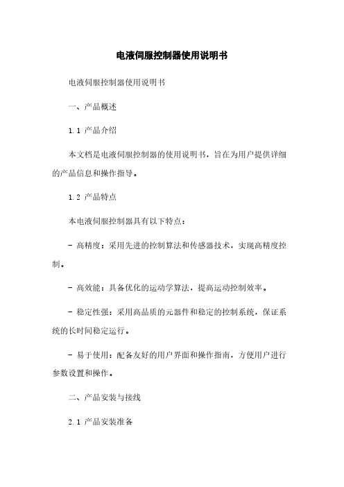
电液伺服控制器使用说明书电液伺服控制器使用说明书一、产品概述1.1 产品介绍本文档是电液伺服控制器的使用说明书,旨在为用户提供详细的产品信息和操作指导。
1.2 产品特点本电液伺服控制器具有以下特点:- 高精度:采用先进的控制算法和传感器技术,实现高精度控制。
- 高效能:具备优化的运动学算法,提高运动控制效率。
- 稳定性强:采用高品质的元器件和稳定的控制系统,保证系统的长时间稳定运行。
- 易于使用:配备友好的用户界面和操作指南,方便用户进行参数设置和操作。
二、产品安装与接线2.1 产品安装准备在进行产品安装之前,您需要准备以下工具和材料:- 螺丝刀- 螺丝- 螺母- 接线端子- 电缆2.2 产品安装步骤步骤1:准备好安装位置,确保其平整和稳定。
步骤2:将电液伺服控制器放置在安装位置,并使用螺丝固定。
步骤3:根据产品规格书和接线图,将相关电缆连接到控制器的接线端子上。
步骤4:检查接线是否正确连接,并确保连接牢固。
三、产品参数配置3.1 参数说明电液伺服控制器具有多种参数可供用户进行配置,包括但不限于:- 控制模式选择:位置控制、速度控制、力矩控制等。
- 响应速度调整:根据实际需求,调整伺服系统的响应速度。
- 限位设置:设置运动范围的限位,避免超出运动范围造成损坏。
- 反馈信号调整:根据实际运动需求,调整反馈信号的增益和灵敏度。
3.2 参数配置步骤步骤1:打开电液伺服控制器的电源,确保电源供应正常。
步骤2:通过控制器上的界面或软件,进入参数配置界面。
步骤3:根据实际需求,逐步配置各项参数,保存并应用配置。
四、产品操作指南4.1 控制器启停步骤1:按下控制器上的启动按钮,控制器开始运行。
步骤2:按下停止按钮,控制器停止运行。
4.2 控制模式切换步骤1:进入参数配置界面。
步骤2:选择控制模式选项。
步骤3:保存并应用配置。
4.3 运动指令输入步骤1:选择所需的运动指令类型(位置、速度、力矩等)。
步骤2:通过控制器上的界面或软件,输入运动指令。
盛迈 SM30 通用伺服驱动器用户手册说明书

SM30 Servo Drive User Manual浙江盛迈电气技术有限公司Zhejiang Synmot Electrical Technology Co.,Ltd [V1.1]SM30通用伺服驱动器用户手册序言感谢您购买并使用浙江盛迈电气技术有限公司生产的SM30系列通用伺服驱动器。
浙江盛迈电气技术有限公司是伺服电机和伺服驱动器的专业生产厂家,产品的功率等级涵盖:400W - 160kW的全系列伺服电机和伺服驱动器。
盛迈SM30系列伺服驱动器是专门为驱动永磁同步电机(PMSM)而开发的一款通用伺服驱动器,该系列伺服驱动器容量范围涵盖广(额定功率0.4kW~160kW),能够实现位置、速度、扭矩等通用伺服控制功能,广泛应用于各类自动化设备。
SM30系列伺服驱动器适用于各种应用场合,支持多种位置反馈装置,包括增量式编码器、绝对值编码器和旋转变压器等;支持多种通讯协议,包括Modbus、CANopen 和EtherCAT等,以高性能的DSP为核心,结合先进的控制算法,满足各种伺服控制的需求。
本手册为SM30系列伺服驱动器的操作指导手册,请妥善保存以便随时查阅。
本手册提供给使用者安全注意事项、产品信息与选型、安装与接线、参数设置、运行与调整、通信功能、故障诊断及日常保养与维护的相关注意事项及指导。
为正确使用本系列伺服驱动器,充分发挥产品的卓越性能并确保使用者和设备的安全,在使用SM30系列伺服驱动器之前,请您务必详细阅读本手册。
不正确的使用可能会造成驱动器运行异常、发生故障、降低使用寿命,乃至发生设备损坏、人身伤亡等事故!本手册适合下列使用者参考:◼伺服系统设计者◼安装或配线人员◼工程调试人员◼维护或检查人员如果您在使用上存在疑问,请咨询经销商或者本公司客服中心。
由于致力于伺服驱动器的不断改进和优化,因此本公司提供的资料如有改变,恕不另行通知。
可通过本公司官网 下载最新版本。
注意:本说明书只针对通用伺服应用,对于电液伺服的用户,请查阅:《盛迈伺服驱动器使用说明 - 液压应用》有关作业安全标识的叙述,其内容十分重要,请务必遵守。
西门子 SKC32.. 24V 电液伺服执行器 使用手册说明书

with a40 mm stroke● SKC32.. Operating voltage AC 230 V, 3-position control signal● SKC82.. Operating voltage AC 24 V, 3-position control signal● SKC6.. Operating voltage AC 24 V,– Control signal DC 0...10 V, 4...20 mA or 0...1000 Ω– SKC62/MO RS-485 for Modbus RTU communication– Selection of flow characteristic, position feedback, stroke calibration, LED status indication, override control– SKC62UA with selection of direction of operation, stroke limit control, sequence control with adjustable start point and operation range, operation of frost protection monitors QAF21.. and QAF61..● Positioning force 2800 N● Versions with or without spring-return function● For direct mounting on valves; no adjustments required● Manual adjuster and position indicator● Optional functions with auxiliary switches, potentiometer and stem heater● SKC..U are UL-approvedFor the operation of Siemens 2-port and 3-port valves of the types VVF.. and VXF.. with a 40 mm stroke as control and safety shut-off valves in heating, ventilation and air conditioning systems.Principle of electro-hydraulic actuators1 Manual adjuster2 Pressure cylinder3 Suction chamber4 Return spring5 Solenoid valve6 Hydraulic pump7 Piston8 Pressure chamber9 Position indicator (0 to 1)10 Coupling11 Valve stem12 PlugValve closed Valve openedOpening thevalveThe hydraulic pump [6] forces oil from the suction chamber [3] to thepressure chamber [8], thereby moving the pressure cylinder [2] downwards.The valve stem [11] retracts and the valve opens. Simultaneously, the returnspring [4] is compressed.Closing thevalveActivating the solenoid valve [5] allows the oil in the pressure chamber toflow back into the suction chamber. The compressed return spring movesthe pressure cylinder upwards. The valve stem extends and the valvecloses.ManualoperationmodeFor manual operation, swing out the crank so that the display windowbecomes visible. By rotating the crank clockwise, the pressure cylinder ismoved downwards. The display window shows the engagement bar and/orthe scale dial with stroke indication.In the manual operation mode, the positioning signals Y and Z can furtheropen the valve but cannot move to the 0 % stroke position of the valve. Toretain the manually set position, switch off the power supply or disconnectthe positioning signals Y and Z. The crank remains swung out and in thedisplay window the red indicator dial remains visible.Hinweis:When setting the controller to manual operation for a longerperiod of time, we recommend adjusting the actuator with themanual adjuster to the desired position. This guarantees thatthe actuator remains in this position for that period of time.Attention: Do not forget to switch back to automatic operationafter the controller is set back to automatic control.2Automatic operation mode For automatic operation, turn the manual adjuster clockwise to the end stop. The pressure cylinder moves upwards to the 0% stroke position of the valve. In the display window, the read scale disappears. Afterwards, swing the crank closed.Minimal volumetric flow The actuator can be manually adjusted to a stroke position > 0%, allowing its use in applications requiring a constant minimal volumetric flow.SKC32.. SKC82..3-position control signal The actuator is controlled by a 3-position signal either via terminals Y1 or Y2 and generates the desired stroke, which is transferred to the valve stem:● Voltage on Y1: Piston extends Valve opens● Voltage on Y2: Piston retracts Valve closes● No voltage on Y1 and Y2: Piston and valve stem remain in therespective positionSKC62.. SKC60Y positioning signalDC 0...10 V and/or 0...1000 Ω, DC 4...20 mA The actuator is either controlled via terminal Y or override control Z. The positioning signals generate the desired stroke by means of the above described principle of operation, which is transferred to the valve stem: ● Signal Y increasing: Piston extends Valve opens ● Signal Y decreasing: Piston retracts Valve closes ● Signal Y constant: Piston and valve stem remain in therespective position● Override control Z: See Functions [➙8]Frost protection monitor Frost protection thermostat A frost protection thermostat can be connected to the SKC6.. actuator. The added signals from the frost protection monitors QAF21.. and QAF61..require the use of SKC62UA actuators. Notes on special programming of the electronics are described under Electronics [➙5].Connection diagrams for operation with frost protection thermostat or frost protection monitor can be found under Connection diagrams [➙26].4ElectronicsSKC601)1 Connection terminals2 DIL switches3 LED status indication 4Stroke calibration1) From version ..L onwardSKC60 2), SKC62..1 Connection terminals2 DIL switches3 LED status indication 4Stroke calibration2) Up to and including version ..KSKC62UA1 Connection terminals2 DIL switches3 LED status indication4 Stroke calibration5 Rotary switch UP (factory setting 0) 6Rotary switch LOSKC62/MOThe Modbus converter is designed for analog control at 0...10 V.Keep the analog signal setting on the actuator as is (switch 1 to OFF); adjustment notpermitted.The actuators are factory configured for equal-percentage characteristic.DIL switch (internal actuator characteristic changeover) to "log" (switch 2 to OFF).FunctionsSpring-return functionThe SKC32.61.., SKC82.61.. and SKC62.., which feature a spring-return function,incorporate a solenoid valve which opens if the control signal or power fails. The returnspring causes the actuator to move to the 0% stroke position and closes the valve.CalibrationSKC60, SKC62.., SKC62/MOIn order to determine the stroke positions 0% and 100% in the valve, calibration is requiredon initial commissioning.♦Mechanical coupling of the actuator SKC6.. with a Siemens valve.Actuator must bin in …Automatic operation mode“ enabling stroke calibration to capture the effective 0% and 100% values.♦AC 24 V power supply applied.♦Housing cover removed.1.Short-circuit contacts in calibration slot (e.g. with ascrewdriver) and trigger calibration process.2. Actuator moves to 0% stroke position [1].♋Valve closes.3. Actuator moves to 100% stroke position [2].♋Valve opens.♋Measured values are stored. LED flashes grün, positioningfeedback U inactive♋Normal operation:Actuator moves to the position [3] as indicated by signalsY or Z.LED is lit green permanently, positioning feedback Uactive, values correspond to the actual positions.A red lit LED on the actuator indicates a calibration error.6The LED on the SKC62/MO cable adapter flashes red during the calibration, as the positioning signal Y and the positioning feedback U do not correspond anymore. This is interpreted as a blockage and thus indicated as an error.necessary, the calibration can be repeated any number of times.LED indication of operational statusSKC60, SKC62.., SKC62/MOThe dual-colored LED indicating the operational status is visible when the cover is removed.As a general rule, the LED can only assume the states shown above – continuously lit red or green, flashing red or green, or off/dark.8Override control ZSKC60, SKC62..The override control input Z can be operated in the following modes of operation:Shown operation modes are based on the factory setting “direct acting”.Y-input has no effect in Z-mode..Selection of direction of operationSKC60 (from version ..L), SKC62UA● With normally-closed valves, “direct acting” means that with a signal input of 0 V, thevalve closes (applies to all Siemens valves listed under Equipment combinations [➙12]). ● With normally-open valves, “direct acting” means that with a signal input of 0 V, the valveis open.The mechanical spring-return function is not affected by the direction of operation selected.Stroke limit control and sequence controlSKC62UA* Operating range of QAF21.. (see below)** Operating range of QAF61.. (see below)*** The smallest adjustment possible is 3 V; control with 0...30 V is only possible via Y.Stroke control with QAF21.. / QAF61.. signal additionSKC62UA101) Approbation: CE 2) Approbation: CE, UL 3) Only available in France4) Enhanced functions, from version ..L onward: Direction of operation, fail-in-place5)Enhanced functions: Direction of operation, stroke control limit, sequence control, signal additionScope of deliveryThe actuator, valve and accessories are supplied in separate packaging and not assembled prior to delivery.Accessories / spare partsAccessories0…1000 ΩFor the combination SIMATIC S5/S7 and use of positioningfeedback, we recommend actuators with DC 0...9.8 VThe signal peaks that occur in the potentiometer ASZ7.3may result in error messages on Siemens SIMATIC. This isnot the case when combined with Siemens HVACcontrollers. The reason is that SIMATIC has a higherresolution and faster response time.Use the potentiometer as voltage divider on the 3-wireconnection. Powering the potentiometer over the wiper mayshorten the life cycle of the potentiometer. Signal peaksincrease in frequency and scope over the lifespan in this For more information, see Technical data [➙19]Ordering (example)1)Specify stock number if available.Spare parts1)Hand control, blue with mechanical partsEquipment combinations2-port valves VV.. (control or safety shut-off valves)Admissible differential pressures Δp max and closing pressures Δp s: cf. relevant valve data sheets1)Valves are no longer available3-port valves VX.. (control valves for “mixing” and “distribution”)Admissible differential pressures Δp max and closing pressures Δp s: cf. relevant valve data sheets1)Valves are no longer availableThird-party valves with strokes between 6...20mm can be motorized, provided they are “closed with the de-energized” fail-safe mechanism and provided that the necessary mechanical coupling is available. For SKC32.. and SKC82.. the Y1 signal must be routed via an additional, freely adjustable end switch (ASC9.3) to limit the stroke.We recommend that you contact your local Siemens office for the necessary information.Related documents such as environmental declarations, CE declarations, etc., can be downloaded at the following Internet address:/bt/downloadSafetyEngineeringConduct the electrical connections in accordance with local regulations on electricalinstallations as well as the section Connection diagrams [➙26].Observe admissible temperatures, see Use [➙2] and Technical data [➙19].If an auxiliary switch is used, its switching point should be indicated on the plant schematic.Every actuator must be driven by a dedicated controller, see Connection diagrams [➙26].Mounting Instructions 74 319 0324 0 for fitting the actuator to the valve and A5W00027551 for SKC62/MO are enclosed in the actuator packaging. The instructions for accessories are enclosed with the accessories themselves (see Product documentation [➙13]).Mounting positionsCommissioningWhen commissioning the system, check the wiring and functions, and set any auxiliary switches and potentiometers as necessary, or check the existing settings.The manual adjuster must be rotated counter-clockwise to the end stop.This causes the Siemens valves, types VVF.. und VXF.. to close (stroke = 0 %).Automatic operationFor automatic operation, the crank [2] on the manual adjustment knob [1] must be engaged.If not engaged, turn the crank counter-clockwise until the display window [3] shows neitherthe scale [4] nor the crank engagement bar.Manual operationFor manual operation, swing out the crank [2] so that the display window [3] becomes visible.By rotating the crank or the manual adjustment knob [1], the display window shows theengagement bar and/or the scale dial [4] with stroke indication.Engaged crank [2] on the manual adjustment knob [1]Swung-out crank; display window [3] Display window with scale dial [4] and stroke indicationin mmMaintenanceThe actuators are maintenance-free.When servicing the control device:WARNINGRisk of burns from hot actuator bracketsThe actuator brackets on heating plants can also become hot from the contact with the hotRecommendation SKC6..:Trigger stroke calibration after maintenance.Repair:See Spare parts [➙12]DisposalWarrantyTechnical data on specific applications are valid only together with Siemens products listedunder "Equipment combinations". Siemens rejects any and all warranties in the event thatthird-party products are used.1)At room temperature (23 °C); low ambient temperatures or high Δp may prolong these times2)From version ..L onward3)AWG = American wire gauge4)The documents can be downloaded at /bt/downloadInternal diagramsSKC32..SKC82..SKC6..Connection terminalsSKC6..SKC62/MOAuxiliary switch ASC1.6Connection diagramsSKC32..*)Only SKC62UA: only with sequence control and the appropriate selector switch settings, see Electronics [➙5], Functions [➙6]ActuatorControllerSystem potentialSystem neutralReference line (Modbus RTU) Bus + (Modbus RTU)Bus - (Modbus RTU)ActuatorAll dimensions in mmExternal Modbus converterAll dimensions in mm。
CSDY1射流管电液伺服阀产品说明书

精心整理CSDY1射流管电液伺服阀产品说明书编制:校对:审核:一、CSDY1二、图1是被夹牢在阀芯的中心位置。
高压油连续地从供油腔Ps通过滤油器及固定节流孔,到射流管喷嘴向两个接受孔喷射,接受孔分别与阀芯两端控制腔相通。
当力矩马达线圈组件输入控制电流时,由于控制磁通和极化磁通的相互作用,在衔铁上产生一个力矩,该力矩使衔铁组件绕弹簧管旋转,从而使射流管喷嘴运动导致两个接受孔腔产生压差引起阀芯位移,且一直持续到由反馈弹簧组件弯曲产生的反馈力矩与控制电流产生的控制力矩相平衡为止。
由于阀芯位移与反馈力矩成比例,控制力矩与控制电流成比例,伺服阀的输出流量与阀芯位移成比例,所以伺服阀的输出流量与输入的指令控制电信号亦成比例,若给伺服阀输入反向电控信号,则伺服阀就有反向流量输出。
三、1234≤5567891011≥40(用于低频控制系列)12、相频宽(-90°)(HZ)≥90四、线圈连接方法:伺服阀线圈的连接方法,插销头标号,外引出线颜色及控制电流的极性等参照下表和射流管电液伺服阀安装图(图2)1、冲洗板1件2、伺服阀接口处o型圈10.2×1.94件3、插头CX2—4M1件4、滤油器组件(含密封圈)1件五、概述:CSDY1系列射流管电液伺服阀是力反馈型两级流量伺服控制阀,具有性能良好,抗污染能力强,安全可靠以及寿命长的突出特点,适用于电液伺服系统的位置、速度、加速度和力的控制。
六、结构原理:图1是CSDY1系列射流管电液伺服阀的原理图,力矩马达采用永磁力矩马达,由两个永七、1、供油压力范围(MPa)2.1~31.52、额定供油压力(MPa)20.63、额定流量(L/min)2—40(按用户要求)4、滞环(%)≤3≤5(用于低频控制系统)5、分辨率(%)≤0.256、线性度(%)≤7.57、对称度(%)≤108、压力增益(%Ps/1%In)≥309、静耗流量(L/min)≤0.45+3%Qn八、注意事项:1、伺服阀安装前应先装上随带附件:冲洗板。
MTS电液伺服试验机使用说明步骤
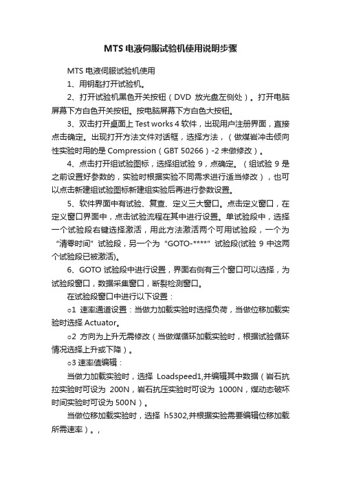
MTS电液伺服试验机使用说明步骤MTS电液伺服试验机使用1、用钥匙打开试验机。
2、打开试验机黑色开关按钮(DVD放光盘左侧处)。
打开电脑屏幕下方白色开关按钮。
按电脑屏幕下方白色大按钮。
3、双击打开桌面上Test works 4软件,出现用户注册界面,直接点击确定。
出现打开方法文件对话框,选择方法,(做煤岩冲击倾向性实验时用的是Compression(GBT 50266)-2未做修改)。
4、点击打开组试验图标,选择组试验9,点确定。
(组试验9是之前设置好参数的,实验时根据实验不同需求进行适当修改),也可以点击新建组试验图标新建组实验后再进行参数设置。
5、软件界面中有试验、复查、定义三大窗口。
点击定义窗口,在定义窗口界面中,点击试验流程在其中进行设置。
单试验段中,选择一个试验段右键选择激活,用此方法激活两个可用试验段,一个为“清零时间”试验段,另一个为“GOTO-****”试验段(试验9中这两个试验段已被激活)。
6、GOTO试验段中进行设置,界面右侧有三个窗口可以选择,为试验段窗口,数据采集窗口,断裂检测窗口。
在试验段窗口中进行以下设置:○1速率通道设置:当做力加载实验时选择负荷,当做位移加载实验时选择Actuator。
○2方向为上升无需修改(当做煤循环加载实验时,根据试验循环情况选择上升或下降)。
○3速率值编辑:当做力加载实验时,选择Loadspeed1,并编辑其中数据(岩石抗拉实验时可设为200N,岩石抗压实验时可设为1000N,煤动态破坏时间实验时可设为500N)。
当做位移加载实验时,选择h5302,并根据实验需要编辑位移加载所需速率)。
,○4做力加载实验时,需要点击“PID参数…”导入PID参数,选择Loadspeed(up).pid,做位移加载实验时不需设置PID参数。
在数据采集窗口中进行以下设置:选择匀速采集法,并点编辑修改采样频率,做动态破坏时间实验时设为150HZ,其它实验时无需设置这么大,设置为10HZ。
电液伺服控制

电液伺服控制1. 引言电液伺服控制是一种在工业自动化领域广泛应用的控制技术,通过控制电液伺服系统的输出来实现对机械装置的精确控制。
本文将介绍电液伺服控制的基本原理、控制策略和应用领域。
2. 电液伺服系统结构电液伺服系统由执行机构、传感器、控制器和液压装置等组成。
执行机构一般由液压缸和阀门组成,传感器用于对执行机构的运动状态进行反馈,控制器根据传感器反馈的信息进行计算和决策,液压装置则负责产生并传递液压能量。
3. 电液伺服控制原理电液伺服控制的基本原理是通过改变液压系统的压力和流量来实现对执行机构的运动控制。
控制器根据预定的信号和传感器反馈的信息计算出对应的控制指令,然后通过控制阀控制液压系统的工作状态,从而实现对执行机构的控制。
4. 电液伺服控制策略电液伺服控制有多种控制策略,常见的包括位置控制、速度控制和力控制。
位置控制是通过对液压缸的运动位置进行控制,实现对机械装置位置的精确控制。
速度控制则是控制液压缸的运动速度,实现对机械装置运动速度的精确控制。
力控制则是控制液压系统的输出力,实现对机械装置施加的力的精确控制。
5. 电液伺服控制的特点电液伺服控制具有以下特点:•高精度:电液伺服控制可以实现对机械装置位置、速度和力的精确控制,满足工业自动化对精度的要求。
•响应快:电液伺服控制系统的响应速度较快,可以实现快速而准确的控制。
•高可靠性:电液伺服系统采用液压传动,具有较高的可靠性和稳定性。
•适应性强:电液伺服控制适用于各种不同工况和负载情况下的控制需求。
6. 电液伺服控制的应用领域电液伺服控制广泛应用于各个工业领域,包括机床、起重机械、注塑机、机器人等。
在机床行业中,电液伺服控制可实现高精度的切削加工;在起重机械领域,电液伺服控制可以实现大力矩的精确控制,提高起重机械的工作效率;在注塑机和机器人领域,电液伺服控制可以实现高速、灵活的动作控制,提高生产效率和产品质量。
7. 总结电液伺服控制是一种在工业自动化领域应用广泛的控制技术,通过控制液压系统的输出来实现对机械装置的精确控制。
ZETA伺服控制器用户使用手册_TRT

ZETA伺服控制器用户手册西安陕鼓动力股份有限公司杭州哲达科技股份有限公司1 .概述 (2)2.产品外观与型号规格 (2)2.1 外观尺寸 (2)2.2型号规格 (2)3.工作原理 (3)4.主要功能 (4)4.1控制功能 (4)4.2参数调整功能 (4)4.3信号丢失报警与记忆功能 (4)4.4通信功能 (5)4.5高级算法嵌入功能 (5)5.安装和接线 (5)5.1安装 (5)5.2接线 (7)6.主要技术参数和性能指标 (12)7.选型使用说明 (12)8.伺服控制器的调校 (13)8.1静叶伺服控制器调校 (13)8.2旁通阀伺服控制器调校 (14)9.我公司的联系方法 (16)ZetaZETA系列伺服控制器1.概述ZETA品牌ZSA系列伺服控制器是专为陕鼓3H-TRT系统配备的高精度智能型伺服控制器。
该控制器不仅具备高精度位置控制、零点与量程调整、正反作用切换和信号丢失报警等功能,而且针对TRT装置控制需求设计有指令信号和反馈信号丢失记忆功能,保证静叶和旁通阀在信号丢失的情况下不发生误动作。
ZETA伺服控制器控制精度高、分辨率高、漂移小、抗干扰能力强、现场调试十分方便。
其设计充分考虑了行业用户的特点,具有很强的针对性。
2.产品外观与型号规格2.1外观尺寸ZETA品牌ZSA系列伺服控制器外观如图1所示,外形尺寸(W X H >D)为320>200>85mm,该机箱还可内置两个完全独立的伺服控制器,即二通道伺服控制图1 ZETA伺服控制器外观图2.2型号规格ZETA的ZSA系列伺服控制器型号规格包括:ZSA-1C-1T :单CPU 单通道伺服控制器,TRT 专用;ZSA-2C-仃:单CPU 双通道伺服控制器,TRT 专用;ZSA-3C-仃:单CPU 三通道伺服控制器,TRT 专用;ZSA-2C-2T :双CPU 二通道伺服控制器,TRT 专用。
3. 工作原理ZETA 的ZSA 系列伺服控制器工作原理图如图2所示。
电液伺服阀使用方法说明书

电液伺服阀使用方法说明书使用方法说明书一、产品概述电液伺服阀是一种用于控制液压系统的装置,通过电流信号控制阀芯的运动,从而精确地调节液压系统的压力和流量。
本说明书将详细介绍电液伺服阀的使用方法及相关注意事项。
二、安装1.确认电源:确保电源电压与电液伺服阀的额定电压相符。
2.安装定位:将电液伺服阀安装在与液压系统相连的位置,并确保其位置固定稳定。
3.连接管路:根据液压系统的设计要求,正确连接电液伺服阀的进、出口管路。
4.接线操作:根据电液伺服阀的接线图,正确连接电源线和控制信号线。
三、调试1.启动液压系统:确保液压系统的操作条件正常,启动系统并确保润滑液正常供给。
2.检查电液伺服阀:检查电液伺服阀的工作状态,确认其是否正常。
3.调节参数:通过液压系统的控制设备,调节电液伺服阀的参数,包括压力、流量等,以达到系统的要求。
4.试运行:在调试过程中,进行试运行以测试电液伺服阀的工作效果,并对其进行调整和优化。
四、使用注意事项1.操作要求:在使用电液伺服阀时,请按照相应的操作要求进行操作,切勿过度使用或反复启动停止。
2.温度控制:请确保电液伺服阀工作环境的温度在允许范围内,并避免过高的温度对其产生影响。
3.保护措施:在长时间停用电液伺服阀时,请采取相应的保护措施,如加装防尘罩、定期保养等。
4.维护保养:定期检查电液伺服阀的工作状态,及时清洁阀体和阀芯,并检查相关零部件是否磨损或需要更换。
五、故障排除在使用过程中,若出现以下情况,请检查并排除故障:1.阀芯无法运动或运动不灵敏:请检查电源电压是否正常,电液伺服阀是否正常供电。
2.液压系统无法调节:请检查电液伺服阀的参数设置是否正确,液压系统的其他部件是否正常工作。
3.频繁泄漏:请检查电液伺服阀的密封件是否损坏,是否需要更换。
六、维修与保养1.保养周期:请按照电液伺服阀的使用情况及使用环境,制定相应的保养周期和保养计划。
2.防尘处理:定期清洁电液伺服阀的外部表面,并加装防尘罩以避免灰尘对其产生影响。
- 1、下载文档前请自行甄别文档内容的完整性,平台不提供额外的编辑、内容补充、找答案等附加服务。
- 2、"仅部分预览"的文档,不可在线预览部分如存在完整性等问题,可反馈申请退款(可完整预览的文档不适用该条件!)。
- 3、如文档侵犯您的权益,请联系客服反馈,我们会尽快为您处理(人工客服工作时间:9:00-18:30)。
图 8:两线制仪表接线示意图
3:模拟量输出
AO+ AO负载
图 9:模拟量输出接线示意图
4:开关量输入
DI+ DI开关
图 10:开关量输入接线示意图
5:开关量输出
RL
V
DONO DOCOM
图 11:开关量输出接线示意图
接线端子图:
端子定义说明见下表: 表 1、接线端子定义 端子序号 24V+ 24V24V+ 24VAO1+ AO1通道定义 24V 正 24V 负 24V 正 24V 负 第二路 DC24V 电源 第一路 DC24V 电源 说明
输出 DC24V+ 输出 DC24V-
给控制室指示阀实际位置信号 4-20ma 给控制室指示手动给定值大小 4-20ma
外供 DC24V 电源
指令信号+ 指令信号- 位置反馈信号+ 位置反馈信号-
LVDT1 初级线圈信号 LVDT1 初级线圈信号 LVDT1 次级线圈信号+ LVDT1 次级线圈信号LVDT1 次级线圈信号+ LVDT1 次级线圈信号LVDT2 初级线圈信号 LVDT2 初级线圈信号 LVDT2 次级线圈信号+
备用 ⊥
备用以太网 RJ45 接口 机壳接地
备用以太网 RJ45 接口 机壳接地
应用领域:
SC900 液压伺服控制器设计用于油动机位置的电液伺服控制,可适用于: 1 、 轴流压缩机静叶角度电液伺服控制。 2 、 TRT 高炉余压发电系统中液动启动阀、膨胀机静叶角度电液伺服控制和快速旁通阀 开度控制系统。 3 、 汽轮机调节门电液伺服系统。 4 、 燃气轮机燃料控制阀电液伺服系统。 主要应用行业包括石油化工行业、冶金行业、 食品行业、 制药行业、电力发电等行业。
接收控制室的 4~20mA 指令信号
接收现场来的位置反馈信号 4~ 20mA
差动变压器式传感器 1 初级线圈信 号 差动变压器式传感器 1 次级线圈信 号 差动变压器式传感器 1 次级线圈信 号 差动变压器式传感器 2 初级线圈信 号 差动变压器式传感器 2 次级线圈信
A2B2+ B2DO1no DO1com DO2no DO2com DO3no DO3com DO4no DO4com DI1+ DI1DI2+ DI2DI3+ DI3DI4+ DI4Com1Com1+ GND Com2Com2+ GND Com3Com3+ GND NC
SC900 电液伺服阀控制器
用户手册
(第一版) 第一版)
西安强源电气有限公司
xi'an qiangyuan electric apparatus co., ltd
2014 年 9 月
SC900 电液伺服 电液伺服阀 伺服阀控制器简介 控制器简介
概述
本伺服控制器是全数字式智能控制器,可直接驱动 MOOG 阀、BD 阀、ATOS 阀等电 液伺服阀,与就地的液压部件(伺服阀、油动机、行程反馈传感器等)配合,完成对油动 机的位置闭环控制。 该控制器基于高性能实时操作系统平台,最大控制周期不超过 2 毫秒;使用双路冗余 24V 电源供电;可接受 2 路位移传感器(LVDT)冗余反馈信号或 1 路 4~20mA 位置 反馈信号;接收 1 路 4~20mA 指令信号;1 路伺服功放控制输出,输出电流能力 -200mA~200mA 以内,可通过参数配置适应 4-20ma、±40ma、±60ma 控制信号的各种 电液伺服阀;2 路 4~20mA 电流输出(一路作为给控制室指示实际位置,另一路作为给 控制室指示手动给定值大小),4 路干接点输出(一路手动状态输出,一路反馈信号故障, 一路指令信号故障, 一路控制器故障),4 路干接点输入(一路手自动状态输入,一路手 动增, 一路手动减, 一路跳机信号) ,对外通讯接口齐全: 1 路 RS485 通讯口, MODBUS 通讯协议,1 路 ProfiBus-DP 接口(配 GSD 文件,可作为西门子模块挂接在西门子 300 或 400 系统中),1 路 CAN 接口,一路工业以太网口。使用过程中,用户可以根据自己 需求对零位位置和满量程大小进行自动整定,标定调校不用任何电位器,包括各种设置参 数(PID 参数,LVDT 振荡频率、LVDT 振荡幅度等)通过控制器和 PC 机的以太网口连 接,运行 windos 版 SC900 PC 设置软件(可实时显示各种参数)完成,在调校过程中将参 数值存入 E2PROM 电擦除芯片记忆,当控制器被复位或重新启动,调校结果参数值会被 重新读入,永不丢失。
号 差动变压器式传感器 2 次级线圈信 号 无源开出点,1A/30VDC,
手动状态输出
无源开出点,1A/30VDC,
反馈信号故障输出
无源开出点,1A/30VDC,
指令信号故障,
无源开出点,1A/30VDC,
DO4 控制器故障
自带查询电压,要求干接点输入 ,
手自动状态输入
自带查询电压,要求干接点输入 ,
LVDT2 次级线圈信号LVDT2 次级线圈信号+ LVDT2 次级线圈信号开关量 1 输出 开关量 1 输出 开关量 2 输出 开关量 2 输出 开关量 3 输出 开关量 3 输出 开关量 4 输出 开关量 4 输出 开入量 1+ 开入量 1- 开入量 2+ 开入量 2- 开入量 3+ 开入量 3- 开入量 4+ 开入量 4- 485 接口+ 485 接口公共地 Probus 接口+ Probus 接口公共地 CAN 接口+ CAN 接口公共地 备用
手动增输入
自带查询电压,要求干接点输入 ,
手动减输入
自带查询电压,要求干接点输入 ,
紧急停机输入
485 接口
Probus 接口
CAN 接口
备用
VO+ VOTCP
输出 DC24V+ 输出 DC24V以太网 RJ45 接口
外供 DC24V 电源
10M-100M 自适应以态网接口拔式接线端子,接线牢靠,接线、拆线调试省时方便 MTBF: 100000 小时 工作环境温度: -20 ℃ ~70 ℃ 工作湿度: 5%~90% 相对湿度,不凝结
存储温度: -15 ℃ ~65 ℃
存储湿度: 5%~90% 相对湿度,不凝结 防护等级: IP20
控制器原理框图:
控制器接收来自上位机(手操器、 PLC、DCS 系统等) 的给定信号(即指令信 号), 给定可通过通讯方式提供或者 AI1 接口以 4~20mA 标准信号提供, 给定可进 行超前滞后调节。 同时控制器接收来自现场的反馈信号, 反馈信号可为现场变送器 的 4~20mA 信号 , 也可直接采用冗余的 LVDT ( 控制器自带调制解调功能)。 当 给定与反馈这二个信号不相等时, 其差值经过 P 或者 PI 运算并经过功率放大后产 生一个驱动信号控制伺服阀的开口方向及大小, 动力油则通过这个开口推动油缸并进 而推动执行机构运动, 安装在执行机构上的位置反馈传感器输出信号也随之改变, 当 它与指令信号相等时, 控制器输出信号保证伺服阀的开口为零, 油缸及执行机构停 止运动。 调节框图如下:
典型接线: 典型接线: 1:LVDT 接线方式
图 2:三线制 LVDT 接线示意图
图 3:四线制 LVDT 接线示意图
图 4:五线制 LVDT 接线示意图
图 5:六线制 LVDT 接线示意图
图 6:直流 LVDT 接线示意图
2:4~20mA 模拟量输入接线方式
AI+ AI四线制仪表
VCC
图 7:四线制仪表接线示意图
开或全关。同时开关量输出告知上位系统反馈断线。 控制输出到电液伺服阀信号丢失(断线)自动保护功能:控制器故障开关量输出 告知上位系统采取进一步措施(闭锁电液伺服阀保位)。
(5)集成灵活多样的接口:RS485,ProfiBus-DP 接口,CAN 接口和以太网多种通讯方式
可供选择。可以通讯方式无障碍连接至上位系统中。 (6)阀特性补偿:可通过死区自动检测,修改曲线线性度和正负差值调节,改进阀的调 节特性。
SC900
模式选择 PID寄存器
通讯指令
给定 信号 校正网络 PID 功放
电液转 换器
4~20mA指令 位置变 送器 阀门 油缸 LVDT
4~20mA指令 反馈配置寄存器
图 1: SC900 功能框图
主要功能:
( 1 ) 控制功能:伺服控制器可以直接驱动 MOOG 阀、 BD 阀等多种伺服阀, 配 合不同变送器和伺服执行机构,可适用于各种现场控制系统。 ( 2 ) 本地控制功能: 通过 DI 通道, 实现本地控制与远程控制切换 ( 3 ) 报警功能:控制器提供指令信号丢失、反馈信号丢失及控制器故障三项报警 功能 ( 4 ) 指令信号丢失自动切换功能: 即自动识别指令信号出现故障时(指令信号断 线), 根据事先的设定, 伺服控制器将控制信号自动切换到本地进行控制,保持输 出电液伺服阀的控制信号维持突然丢失前的数值,同时开关量输出告知上位系统。 现场位置反馈信号丢失自我保护功能: 即自动识别反馈信号丢失(位置传感器坏 或固定螺丝松动超量程或反馈断线), 控制器可程序预先设定控制输出信号保持或全
产品特点:
1 高可靠性: 工业级设计, 高防护等级,完善的通道自诊断 2 高稳定性: 数字化控制, 抗干扰能力强, 控制性能稳定; 3 高易用性: 参数化配置, 平台化设计,集成现场总线技术
技术规格:
控制器供电: 冗余方式, 18~32VDC ,任何一路电源正常供电都可保证控制器正常 工作,带电源诊断 通道自检: 所有通道均支持,包括信号电缆损坏或短路或未连接、超出范围等,可定 义故障输出信号。 控制信号输出: 1 路, 输出电流: -100mA~100mA 以内, 可编程设定 4-20ma、 ±40ma、 ±60ma,±10v 等模式。(负载阻抗≤500Ω),直接驱动各种电液伺服 阀。 模拟量输入信号: 2 路, 4 ~ 20mA (输入阻抗 200Ω),AI1 接受 4~20mA 指 令信号,AI2 接受 4~20mA 位置反馈标准信号 LVDT 输入信号: 2 路, 可适应 3 、 4 、 5 、 6 线制各种 LVDT 模拟量输出信号: 2 路, 4 ~ 20mA (负载阻抗≤500Ω),AO1 为计算机或显示 仪表提供 4-20 mA 实际位置指示,AO2 为为计算机或显示仪表提供 4-20 mA 手动给定值 开关量输入信号: 4 路,干接点输入 ,DI1 手自动状态输入,DI2 手动增,DI3 手动 减,DI4 跳机信号, 开关量输出信号: 4 路干接点输出,1A/30VDC, DO1 手动状态输出,DO2 反馈信号 故障,DO3 指令信号故障, DO4 控制器故障 具有标准的人机界面接口:可以连接 Eview 品牌的人机界面 通讯信号: 1 路 RS485 通讯口, MODBUS 通讯协议 1 路 ProfiBus-DP 接口 1 路 CAN 总线 1 路工业以太网接口