雷赛6000系列运动控制器硬件手册V2.0
雷赛LC5000系列智能产线控制器简易说明书
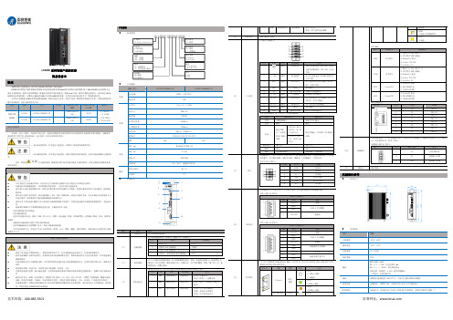
LC5000系列智能产线控制器简易说明书概述感谢您购买雷赛智能自主研发的LC5000系列智能产线控制器!LC5000系列智能产线控制器是雷赛面向先进制造业推出的EtherCAT 总线型运动控制器,基于X86+CODESYS 运动控制平台。
采用全金属机身,提供丰富的网络接口来满足各种项目的扩展需求,搭载Core I CPU ,提供卓越的运算能力,具备高达256轴超强的运动控制性能;内置高达8GB 的DDR4内存和64GB SSD 硬盘,非常适合高负荷运算及工厂整线控制应用。
本手册主要描述LC5000系列控制器的规格、特性及使用方法等。
使用产品前,敬请您仔细阅读本手册,以便更清楚地掌安全注意事项在安装、运行、保养、 检查本产品之前, 请务必仔细阅读本使用说明书以及其他相关设备的所有附带资料,正确使用。
请在熟悉了所有关于设备的知识、安全信息,以及注意事项后使用。
:表示错误使用时,有可能会引起危险,导致死亡或是重伤事故的发生。
:表示错误使用时,有可能会引起危险,导致中度伤害或受到轻伤,也有可能造成物品方面的损害。
此外,即使是中记载的事项,根据状况的不同也可能导致重大事故的发生。
两者记载的内容都很重要,● 只有受到电气设备相关培训、具有充分电气知识的专业维护人员才能进行产品的运行保养。
● 在通电时请勿触碰到端子。
否则有触电的危险性, 并且有可能引起误动作。
● 进行清扫以及拧紧接线端子时,请务必在断开所有外部电源后方可操作。
如果在通电的状态下进行操作,则有触电的危险。
● 要在运行过程中更改程序、执行强制输出、RUN 、STOP 等操作前,请务必先熟读手册,在充分确认安全的情况下方可进行操作。
操作错误有可能导致机械破损及事故发生。
● 请勿从多个外围设备(编程工具)同时更改可编程控制器中的程序。
否则可能会破坏可编程控制器的程序,引起误动作。
●请按照控制器用户手册硬件篇指定的内容,正确使用RTC 电池。
- 请勿用做指定以外的用途。
6000CDT型号的产品说明书

REPEATIMPORTANT SAFETY INFORMATIONRead these instructions.Keep these instructions.Heed all warnings.Follow all instructions.Do not use this apparatus near water.Clean only with dry cloth.This lightning flash with arrowhead symbol within anequilateral triangle is intended to alert the user to thepresence of non-insulated “dangerous voltage” within theproduct’s enclosure that may be of sufficient magnitude toconstitute a risk of electric shock.Warning: To reduce the risk of electric shock, do not removecover (or back) as there are no user-serviceable parts inside.Refer servicing to qualified personnel.The exclamation point within an equilateral triangle isintended to alert the user to the presence of importantoperating and maintenance instructions in the literatureaccompanying the appliance.Do not block any ventilation openings. Install inaccordance with the manufacturer’s instructions.Do not install near any heat sources such as radiators, heatregisters, stoves, or other apparatus (including amplifiers)that produce heat.Do not defeat the safety purpose of the polarized orgrounding-type plug. A polarized plug has two blades with one wider than the other. A grounding plug has two blades and a third grounding prong. The wide blade or the third prong is provided for your safety. If the provided plug does not fit into your outlet, consult an electrician for replacement of the obsolete outlet.Protect the power cord from being walked on or pinched particularly at the plugs, convenience receptacles, and at the point where they exit from the e only with the cart, stand, tripod, bracket, or table specified by the manufacturer, or sold with the apparatus. When a cart or rack is used, use caution when moving the cart/apparatus combination to avoid injury from tip-over. Unplug this apparatus during lightning storms or when unused for long periods of time.Refer all servicing to qualified service personnel. Servicing is required when the apparatus has been damaged in any way, such as power supply cord or plug is damaged, liquid has been spilled or objects have fallen into the apparatus, the apparatus has been exposed to rain or moisture, does not operate normally, or has been dropped.CAUTION: These servicing instructions are for use by qualified service personnel only. To reduce the risk of electric shock, do not perform any servicing other than that contained in the operating instructions unless you are qualified to do so.Do not install this equipment in a confined or built-in space such as a bookcase or similar unit, and keep well ventilated in open space. The ventilation should not be impeded by covering the ventilation openings with items such as newspaper, table-cloths, curtains etc.WARNING: Only use attachments/accessories specified or provided by the manufacturer (such as the exclusive supply adapter, battery etc).WARNING: Please refer to the information on the exterior panel of the enclosure for electrical and safety information before installing or operating the apparatus.WARNING: The battery (battery or batteries or battery pack) shall not be exposed to excessive heat such as sunshine, fire or the like.CAUTION: Danger of explosion if battery is incorrectly replaced. Replace only with the same or equivalent type.WARNING: For the terminals marked with symbol of “ ” may be of sufficient magnitude to constitute a risk of electric shock. The external wiring connected to the terminals requires installation by an instructed person or the used of ready-made leads or cords. Mains Supply: The mains operating voltageof Audiolab 6000 series units is shown on the rear panel. If this voltage does not match the mains voltage in your area, consult your Audiolab dealer about converting the unit.The mains supply fuse on the rear panel is accessible when the IEC mains plug has been removed. In the rare event that it has broken, check for any obvious cause before replacing the fuse with one of the correct rating and type.The fuse values are:220 – 240V (UK, China, etc.) T630mAL 250V Slow Blow 100 – 120V (USA, Japan, etc.) T1AL 250V Slow BlowThis label tells you that the unit contains a laser component. Opening the unit will expose the user to radiation from the laser beam.Placement Welcome to Audiolab 6000 Series.We hope you will enjoy its performance for many years to come.Please read through this manual to obtain the very best performance from 6000CDT.Inputs:• CD disc playback.Outputs:• Optical and coaxial SPDIF digital output.Features:• Automatic equipment activation via 12V trigger output .• Display on/off options.• Auto standby function with function on/off options.UnpackingUnpack the product fully. The carton should contain:• The Audiolab 6000CDT• One IEC power cord suitable for your area.• One Remote handset with two AAA batteries • This instruction manual.lf an item is missing or damaged , report this to your dealer as soon as possible. Retain the packing for safe transport of your unit. If you dispose of the packing, do so with regarding to any recycling regulation in your area.Note: The 6000CDT should be used with the DIGl or OPT outputs connected directly to a preamplifier with inbuilt DAC. 6000CDT is a high performance CD transport that is the perfect partner for otherAudiolab components such as 6000A.The unit is designed to run warm during normal operation but ensure you do not block any ventilation openings.Place the unit on a sturdy shelf or table. If you use an equipment rack,ensure the unit has adequate ventilation and is on its own shelf. To minimize any interference, place the power supply in a stable location as far from sensitive analogue input as possible.Ensure your mains voltage corresponds to the rating plate on the rear of the product’s power supply. If in doubt, consult your dealer. If you move to an area with a different mains voltage,seek advice from an Audiolab appointed dealer or a competent service technician.Fitting Batteries Handset Operation 1 STANDBY Press to bring the unit in/out of Standby2 STORE Press to store a track in Program modeMove to the next track of CD 4 Press and hold to Fast Forward5 Press and hold to Fast Reverse6 DISPLAY Press to toggle the display on/off7 A Press to select 6000A remote mode8 CD Press to select 6000CDT remote mode9 TIME Press to toggle track time remaining and elapsed 10 Press to stop CD 11 Press to eject/load the disc 12 Press to start/pause CD playback13 Press once to replay the current track of CDPress again to move to the previous track of CD14 REPEAT Press to repeat whole CD playback15 PROG Press to program tracks of your choice16 NUMBER KEYSPress to go directly to a track by numberOpen the battery compartment cover, unwrap the supplied AAA batteries and place them in the battery compartment with the correct polarity. Replace the cover.Always use AAA batteries and replace them in sets - never mix old and new batteries.Very weak batteries can leak and damage the handset. Replace them in good time!Note: there is a risk of fire and burns if a battery is handled improperly. Do not disassemble, crush, puncture, short the contacts or dispose of the batteries in fire or water.Do not attempt to open or service a battery. Discard used batteries in full accordance with recycling regulations in force in your area. The handset operates several Audiolab components. The handset buttons shown crossed out are for use with other Audiolab units and are not operational when used with the 6000CDT.Point the handset at the remote receiver and press the relevant key. The handset should be within 15 meters of the player and there must be a clear line of sight between the two units.Trigger Connections Mains Input Digital Outputs Coaxial and Optical outputOne Coaxial and one Optical SPDIF digital output. Connect asuitable Digital coaxial (fully screened) interconnect or opticalcable from the appropriate SPDIF output of the 6000CDT tothe input of a DAC or digital input on your amplifier orpreamplifier.Audiolab 6000CDT has a pair of trigger connections on the rear panel that can activate 6000A’s or any other source’s trigger input. If you have a 6000 system, we advise connecting the triggers. This will enable all 6000 units to be brought in and out of standby using the trigger connections. To connect to your control unit, you will need a cable with one end to match the trigger output of the control unit and other terminating in a 3.5mm jack plug. For Audiolab 6000series, this will be a 3.5mm to 3.5mm interconnect.Before connecting the 6000CDT to the mains supply make sure that all the other connections to your system have been properly and securely made. Make sure the ON/OFF switch on the 6000CDT is switched off. Switch the mains supply off at the wall socket, and then, using the cable supplied, connect the socket on the back of your 6000CDT to an AC supply outlet. The 6000CDT is now ready for operation.630Connect power to all system units. Switch the mains on. Switch on all source units including the 6000CDT. Switch on the power amplifiers.When switching off: switch off the amplifier first before switching off the 6000CDT unless they are trigger enabled.When switching on: The power LED illuminates, the display shows the welcome screen. After a short period the unit boots up.The 6000CDT will enter standby mode after being powered on. Press the “Standby” button to bring the 6000CDT out of standby, the power indicator LED becomes brighter and the displayshows “6000CDT” welcome screen while the unit is getting ready for operation.The Auto Standby feature will, by default, put the unit into standby after 20min of inactivity.This feature can be configured by holding the standby button for 3 seconds and be set to 20min, 1hour or Never. Insert one CD into the slot. The disc information will now display. After reading the track information the disc will stop.Switching On and OffStandby Mode Loading a Disc Playing a Disc Pressto play a disc.Pressto pause a disc, press again to resume play Pressto stop the disc Press to eject the disc Next/Previous Trackto move to the next track.once to replay the current track,twice to move to the previous track.If you exceed the number of tracks on the disc, the player will wrap round and play from track1.If you go past track 1, the player will wrap round and reverse search from the final track on the disc.Forward and Reverse Search during play Press and hold the / on the handset. The forward and reverse search will start.Direct selection of the tracks from the handsetWhen in PROG mode, the time dot is flashing.Track Time Display When in PROG mode, press the Repeat key on the handset to repeat all chosen tracks.Display Setting Pressing the DISPLAY button on the remote to control the display ON/OFF.Select the wanted track directly from the remote key pad. The disc will play forward from the chosen track. If you choose a single digital track (e.g.1) in a disc which contains more than 10 tracks, the player will pause briefly, waiting for you to enter a second digit. If none is entered, player will commence from the entered single-digit track. If the choice is invalid the display reverts to the previous state.You can create a custom program of up to 99 chosen tracks. .Program mode must be accessed when the disc has stopped.Press PROG to enter program mode. Insert the a track number, press STORE to save.To play the program: PressTo stop program play: Press To erase a program from memory: The program is stored in the player’s memory until erased.When the display is OFF: Pressing any key will momentarily switch the display on. After a few moments the display will go off.Repeat Play Press the Repeat key on the handset to repeat all tracks on the disc continuously.Press the Time key to toggle track time remaining and elapsed Program PlayAudiolab Ltd. warrants this product, subject to the terms and conditions below, to be free from defects in materials and workmanship. During the warranty period Audiolab will repair or replace (at Audiolab’s option) this product, or any defective part in this product, if it is found to be defective due to faulty materials, workmanship or function. The warranty period may vary from country to country.Audiolab shall not be liable for any incidental or consequential damages for breach of any express or implied warranty in this product. Except to the extent prohibited by law, this warranty is exclusive and in lieu of all other warranties whatsoever, both express and implied, including, butnot limited to, the warranty of merchantability and fitness for a practical purpose.This warranty provides benefits that are additional to and do not affect your statutory rights as a consumer.Some countries and U.S. states do not allow the exclusion or limitation of incidental or consequential damages or implied warranties so the exclusions in the paragraph above may not apply to you. This warranty gives you specific legal rights, and you may have other statutory rights, which vary from state to state or county to county.To obtain warranty service contact the Audiolab authorized dealer from which you purchased this product. Do not dispatch goods without the prior agreement of the dealer, Audiolab or their authorized distributors.If asked to return products for inspection and/or repair, pack carefully, preferably in the original cartons or packing affording an equal degree of protection, and return prepaid. If unsuitable packaging is used, Audiolab may make a charge for the supply of new packaging.Insurance is recommended and goods are returned at owner’s risk. Audiolab or their authorized distributors cannot be held liable for loss or damage in transit.You must provide proof of purchase/delivery before work can be carried out. Without this proof, any work carried out will be chargeable to you.This warranty is valid only in the county of purchase, applies only to the first purchaser and is not transferable.Accidental damage, fault caused by commercial use, acts of God, incorrect installation, connection or packing, misuse, neglect or careless operation or handling of the product which is not in accordance with Audiolab’s user instructions.1. Repairs or alterations carried out by parties other than Audiolab or its authorized agents or Terms and conditions The warranty starts on the date of purchase (or the date of delivery if this is later).All work will be carried out by Audiolab or its authorized agents or distributors.Any unauthorized repair or modification will void this warranty.If any part is no longer available it will be replaced with a functional replacement part.Any parts that are replaced will become the property of Audiolab.Any repair or replacement under this warranty will not extend the period of warranty.The following are not covered:1. Products where the serial number has been removed, altered or otherwise made illegible.2. Normal wear tear and cosmetic damage.3. Transportation or installation of the product.2. Products are not purchased from an Audiolab authorized dealer.distributors.3. Products that were not new at the time of original purchase.4. Products sold ‘as is’, ‘as seen’ or ‘with all faults’.Repairs or replacements as provided under this warranty are the exclusive remedy of the consumer.How to claim:Measurement made with 230V power supplyDigital Output Voltage Level600±50mVppFrequency response≤0.01dB @ 20-20kHzOutput Impedance75±1 ohmMax Sampling Rate44.1 KHzMax. Power Consumption15WStandby Power Consumption<0.5WPower Requirements240V ~ 50 - 60Hz230V ~ 50 - 60Hz115V ~ 50 - 60Hz100V ~ 50 - 60HzDimensions (mm)(W x H x D) 445 x 300 x 65.5 - including feet, terminals and contr olsCarton Size (mm)(W x H x D) 512 x 467x 146Weight 5.4kg (Net)Corrent disposal of this product. This marking indicates that this product should not bedisposed with other household wastes throughout the EU. To prevent possible harm to theenvironment or human health from uncontrolled waste disposal, recycle it responsible topromote the sustainable reuse of material resources. To return your used device, please usethe return and collection systems or contact the retailer where the product was purchased.They can take this product for environmental safe recycling.。
ABB UnitrOL 6000 Excitation Systems商品说明书

• Industry benchmark in availability• Ultimate control performance keeps synchronous machine within safe limits• Guaranteed grid code compliance through advanced PSS options, validated models and simulation services• Hardware in the Loop simulator, to expedite tuning and site-testing• Simple system operation, monitoring, and maintenance• Pro-active life cycle management throughout the complete life-span of the equipment• 24/7/365 technical support always within your reach, utilizing remote access platforms—UNITROL® 6000 Excitation systems Setting the standard in technology and availabilityand availability2U N ITRO L® E XCITATI O N S YS TE M S Se t ti n g th e S ta n da r d—Setting the standardaBB UnitrOL® excitation systems are a key component in many power generating units used by plant owners and operators to achieve reliability of operations, stability, and fast transient response of their assets, as per grid requirements.The UNITROL® 6000 excitation systems series is specifically designed to serve a wide range of applications:• Generators: steam, gas, nuclear and hydro power plants, nuclear emergency diesel• Motors: steel mills, pulp and paper, chemical, natural gas production plants, refineries UNITROL® 6000 for indirect and static excitation systems comes in the following versions:• UNITROL® 6000 Medium• UNITROL® 6000 X-powerexcitation current [a]3U N ITRO L® E XCITATI O N S YS TE M S U n itr O L® 6000 M ed i U M—UNITROL® 6000 Mediumthe customizable solutionUnitrOL® 6000 Medium is designed for small to medium static excitation systems. it is as well a benchmark in flexibility, reliability and connectivity for brushless and critical steam generating units.With single/double channel configuration (additional backup channel on request) and a wide selectionof thyristor bridge modules, UNITROL® 6000 Medium can be configured to meet all field data and availability requirements.Selected applications• Hydro power plant• Pumped storage power plant• Combined cycle power plant• Critical Steam power plant with brushless excitation, Ifn 200 A, 400 Hz supply Engineered solutions:• Online supply transfer• Electric braking Main Features UNITROL® 6000 Medium Customizable YesDC current rage<1,800 ABackup channel Yes / OptionalConverter redundancy Single, twin, twin + backup Max. converters3H configuration NoConverter types D1, D2, D3, D4, D5PSS2B/2CAPSS NoPEC controller generation2IEC 61850OptionalField breakerAC or DCU n itr O L® 6000 X-P Ow er 4—UNITROL® 6000 X-powerthe solution for large powerapplicationsUnitrOL® 6000 X-power is designed for large power generation unitsand brings a new benchmark in flexibility, reliability and connectivity.With single/double channel control configuration (additional backup controller on request) anda wide selection of thyristor bridge modules, UNITROL® 6000 X-power can be configured to meet all field data and availability requirements. Selected applications• Nuclear power plant, field current Ifn >10,000 A • Underground hydro power plant, Ifn 4,500 A, with redundant air-to-water heat exchanger system • Gas turbine power plant, MEGATROL package with Ifn 6,000 A and static frequency converter 15 MW for turbine starting• Coal-fired power plant, Ifn 3,500 A, power part in IP54 container, detached AVR cabinet with >150 m distance apart• Hydro power plant, Ifn 4,000 A, two DC field circuit breakers, one for DC backup excitation Main Features UNITROL® 6000 X-power Customizable YesDC current rage1,800 A < X < 12,000 A Backup channel Yes / Optional Converter redundancy Single, twin, n-xMax. converters8H configuration YesConverter types D5, UNL13300, UNL14300 PSS2B/2C/4BAPSS YesPEC controller generation3IEC 61850YesField breakerAC (4,000) or DC5U N ITRO L® E XCITATI O N S YS TE M S CO ntr O L fU n C ti O nS—Control functionsall regulation, protection, and monitoring functions required for the secure operation of the generator are included as standard software features. to meet specific demands of any application, the software can easily be configured and adapted for the requirements.Closed-loop control• Voltage regulator with PID filter (AUTO mode)• Field current regulator with PI filter (MAN mode)• Reactive and/or active current droop compensation • Limiter circuits to ensure that the generator operates within safe limits:-Maximum and minimum field current-Maximum stator current, dependent on machine cooling media temperature-P/Q under-excitation-Volt/Hertz• Manual restrict to keep the generator within safe limits, even though controlled in manual mode • Power factor/reactive load control• Power system stabilizerProtection and monitoring functions• Monitoring and protection functions can be freely configured on three action levels:-Alarm signal only-Changeover to redundant circuits-Instantaneous excitation trip to protect theassetsMajor available functions• Overcurrent protection (instantaneous/inverse time)• Volt/Hertz protection• Loss of field protection• Rotor temperature• Thyristor conduction monitoring• Actual value monitoringData and event recordingThe internal event recorder function can handle and store up to 2,000 events, each providedwith a real-time stamp. The data recorder contains a preconfigured part that records a huge set of measurements and internal signals. It is automa-tically triggered in case of a fault, to enable effi-cient troubleshooting and continuous improve m ent with the aim to maximize the availability. Additional free configurable high-speed recorders are available to be utilized during compliance testing or analysis of network events.System time synchronizationThe system clock of all the controllers can be synchronized with a time source by Simple Network Time Protocol (SNTP) with an accuracy of up to 1 ms to allow efficient troubleshooting and align excitation event-logs with other loggers of the plant and minimize the time to get the unit backon the grid.Power system stabilizer (PSS)The PSS function improves the stability of the generator and the transmission system by using the excitation to damp power oscillations.PSS types optionally available for UNITROL® 6000:• PSS 2A/2B/2C in accordance with IEEE standard 421.5-2016• PSS 4B/4C in accordance with IEEE standard 421.5-2016• Adaptive PSS (APSS) developed by ABB Switzerland, which optimizes the PSS settings based on the current network conditions, to maximize availability and avoid trips dueto insufficient damping in weak networksCO ntr O L fU n C ti O nS 6ynchronous machine transient simulator – real time (SMTS-RT 6000)SMTS-RT 6000 is a “Hardware in the loop” simulator, which simulates a generator/motor, its turbine/ load and the grid. The simulator is connected to the excitation system for closed-loop tests to analyze its stationary and transient behavior. The SMTS-RT 6000 reduces the testing time of your machine, saves costs, and serves as ideal training tool for maintenance and operation personnel.Commissioning time can be further reduced bytuning control parameter sets in advance, using the simulator and a UNITROL® 6000 control device.Grid codesUNITROL® 6000 control functionality is prepared to support any grid code. The extensive testing functions and powerful data recorders of theexcitation control terminal (ECT) serve to test, tune, and prove the performance of control, stabilizer and limiter functions. System frequency response can be analyzed quickly and accurately using the built-in white noise generator. This method executes compliance testing in minimal time.Data records are stored in the ECT’s dedicated memory and can be easily copied and integrated into electronic documents.In combination with SMTS-RT 6000, it is possible to simulate the most critical plant or gridconditions, which are typically impossible to testsafely within the real system.—Complexity of power grids, smart grids, microgrids, distrib-uted and variableenergy resources.DistributedgenerationDomestic consumers with some independentgenerationDomestic equipment and vehicles7U N ITRO L® E XCITATI O N S YS TE M S h a r dwa r e CO M P O n entS—Hardware componentsthe system is based on the aC 800PeC high-performance processor family. it is an extension of aBB’s 800xa control platform, developed to meet the fast control requirements of power electronics.ControlThe AC 800PEC control system excels in very high processing speed, providing:• Fast analog and digital process I/Os with a typical cycle time of 400 µs• Fast closed-loop control and regular process logic implemented in a single controller• Low-speed I/Os with a typical cycle time of 10 ms • Very fast programmable logic for converter pulse control and optical communication with cycle time down to 25 nsPower converterThe power converter of each channel is selected to meet the system requirements with respect to maximum field current and voltage. Stringent availability requirements are fulfilled with up to three redundant channels and provisions for online maintenance (optional). ABB has developed a range of thyristor power converters dedicated to direct (static) and indirect excitation systems, for example D1 to D5, UNL13300 and UNL14300.Main features (D1 to D5)• Single- or three-phase AC supply voltage up to 1,080 V• Rated supply frequency from 50 to 480 Hz (16⅔ Hz on request)• Low noise level of cooling fans ≤70 dB(A)• Compact, fully integrated converter and control with an integrated service panelMain features (UNL14300)• AC supply voltage up to 1,500 V• High insulation test voltages up to 7.5 kV• Low noise level of cooling fans ≤70 dB(A)• Active current balance control• Optional:-Redundant fans, replaceable during operation -“Draw-out” design for safe online repair andfunction tests—01 D1–D5 powerconverter—02 UNL14300power converter—02—01CO M M U n i C ati O n fe at U r e S8—Communication featuresthe communication features of UnitrOL® 6000 systems ensure simpleandu ser-friendly human machine interaction, whether it comes to systemcommissioning or integration into the plant control system.Excitation control terminal (ECT)The ECT is a user-friendly human machine interface that enables operation, monitoring,and maintenance of the system. It is a powerful in-dustrial grade touchscreen PC that runs inde-pendently of the system’s controller. Eventsand system data can be recorded over a long period of time. The LCD touchscreen provides the opera-tor with a range of selectable screens showing in-formation on the actual status of the system in graphical and numerical form. The control terminal operates under Windows 10 and can also be in-stalled on any PC for commissioning purposes.Integration into the plant control system Ethernet and fieldbus protocols Modbus-RTU, Mod-bus-TCP, and Profibus DP-V0 as well as IEC 61850 are the main choices for communication with the plant control system. Emergency control signals can be hardwired directly to the control board. Remote servicesRemote services and troubleshooting help reduce costs associated with repair and service time. UNITROL® 6000 is enabled for remote access with the aid of ABB RAP platform or customer internal tools. Thus, the local maintenance team can get the necessary support from ABB service specialists.—01 Excitation Control Terminal operatorscreen selections9U N ITRO L® E XCITATI O N S YS TE M S Ser v i C e a n d SU PP O rt—Service and supportfor life cycle management or technical support, the worldwide network of UnitrOL® specialists is at your service.Installation and commissioningThe professionalism, extensive experience,and multilingual skills of ABB’s engineersensure satisfactory installation and commissioning. TrainingABB University offers standard and customized training courses for UNITROL® 6000 excitation systems. Virtual and on-site training options are available. For detailed training programs, visitw /abbuniversity.Life cycle managementABB’s excitation systems life cycle management model helps the customers extend and maximize the life cycle of their assets at minimum costs. Depending on the product’s life cycle phase,the service specialists recommend necessary actions and approach the clients proactively to inform them of all maintenance, service, and upgrade requirements. We have a comprehensive Excitation Care program to cover all customer maintenance needs.Examples of life cycle services:• Technical support for optimized reliability• Remote services• Maintenance and repairs• Extension, upgrades, and retrofitsComplete life cycle services are guaranteed for the active and classic phases. As soon as the system enters the limited phase, it is recommended to start planning an upgrade, or retrofit the equipment with ABB's latest technology.Complete life cycle services Limited life cycle ser vicesSer v i Ce a n d SU PP O rt 10Technical support• Large global team of certified engineers• Highly experienced experts in ABB excitation systems and combined solutions provide fast and precise technical emergency assistance 24/7, 365 days a year• Remote support available:-24-hour hotline: +41 844 845 845-Email:**************************.com Excitation CareProvides a simple and structured way to support your assets throughout their life cycle. It offers customizable service levels with optional packages to cover different maintenance needs.Benefits• Simplifies service delivery• Reduces maintenance cost• Supports your operations with digital services • Provides access to ABB ability Remote Insights and the Remote Access Platform (RAP) for faster troubleshooting• Increases the reliability of the system by providing proactive maintenance programs• Supports transfer of knowledge through our trainings, offered as virtual or face to face.and Predictive maintenance Grid CodeTrainingTechnicalSupport and Upgrades—ABB LtdExcitation Systemsand Synchronizing Equipment Ch-5300 turgi, Switzerland Phone: +41 (0)58 589 24 86e-Mail:**********.com /unitrol9a K K 107492a 4684© Copyright 2021 aBB. all rights reserved. Specifications subject to change without notice.。
洛克威爾自動化 Kinetix 6000M 整合式驅動馬達用户手册说明书
安裝說明Kinetix 6000M 整合式驅動馬達型號MDF-SB1003、MDF-SB1153、MDF-SB1304主題頁次重要使用者資訊2關於Kinetix 6000M 整合式驅動馬達3產品型錄編號說明4Kinetix 6000M整合式驅動馬達系統電纜圖5IDM 單元接頭和指示燈6開始之前7安裝整合式驅動馬達8產品尺寸11負載力額定值13接頭資料14網路和驅動器狀態指示燈16移除與更換軸鍵和軸密封17電纜和配件套件19規格21馬達過載保護22其他資源232 Kinetix 6000M 整合式驅動馬達洛克威爾自動化出版品編號 MDF-IN001B-ZC-P - 2013 年8月重要使用者資訊在您安裝、設定、操作或維護本產品之前,請參閱本文件以及列在其他資源段落的文件中關於本設備的安裝、組態與操作資訊。
使用者需要熟悉安裝與配線說明,以及所有適用的法規、法律和標準的規定。
安裝、調整、開始服務、使用、組裝、拆卸與維護等活動需要由受過適當訓練的人員遵照適用實施法規來進行。
如果沒有依照製造商指定的方式使用本設備,可能損及設備附帶的保護機制。
洛克威爾自動化公司對任何因為使用或應用本設備而造成的間接或隨之而來的損概不承擔任何責任。
本手冊中所含的範例及圖示僅為示範目的。
由於個別安裝會有許多不同的變數及條件,洛克威爾自動化公司無法對依照範例及圖示指示進行的實際使用狀況負責或提供賠償。
洛克威爾自動化公司對本手冊中所述之資訊、電路、設備或軟體的使用概不承擔任何專利責任。
在取得洛克威爾自動化公司書面同意之前,禁止重製本手冊的部分或全部內容。
在本手冊中,如有需要,我們會使用備註提醒您安全注意事項。
說明特定預防措施的標籤也可能會貼在設備上方或內部。
警告: 顯示可能會在危險環境中爆炸,造成人員受傷、死亡、財產損壞、經濟損失的情況之資訊。
注意事項: 顯示可能造成人員受傷、死亡、財產損壞、經濟損失的實務情況資訊。
注意事項有助於您發現、避免並瞭解危險的後果。
DMC1000B用户手册V2.0
用户手册
Version 2.0
版2010 Leadshine Technology Co., Ltd. All Rights Reserved.
版权说明 本手册版权归深圳市雷赛科技有限公司所有,未经公司书面许 可,任何人不得翻印、翻译和抄袭本手册中的任何内容。 本手册中的信息资料仅供参考。由于改进设计和功能等原因,雷 赛公司保留对本资料的最终解释权,内容如有更改,恕不另行通知。
3 硬件配置与安装.......................................................................................................16
3.1 硬件配置............................................................................................................16 3.2 硬件安装............................................................................................................18
8 附录...........................................................................................................................48
8.1 硬件信号接口表................................................................................................48 8.2 运动控制函数库................................................................................................51 8.3 1000B与 1000 卡之间的一些说明...................................................................59
深圳市雷赛智能控制股份有限公司DM432C数字式步进驱动器使用说明书

深圳市雷赛智能控制股份有限公司地址:深圳市南山区学苑大道1001号南山智园A3栋10-11楼邮编:518000电话:400-885-5521传真:*************Email:********************网址:DM432C数字式步进驱动器使用手册版本:V1.10版权所有不得翻印【使用前请仔细阅读本手册,以免损坏驱动器】深圳市雷赛智能控制股份有限公司版本说明版本日期更改内容V1.002018-09-20V1.102020-03-31增删部分内容目录一、产品简介 (3)1.概述 (3)2.特点 (3)3.应用领域 (3)二、电气、机械和环境指标 (3)1.电气指标 (3)2.使用环境及参数 (3)3.机械安装图 (3)4.加强散热方式 (4)三、驱动器接口和接线介绍 (4)1.接口描述 (4)2.控制信号接口电路 (4)3.控制信号时序图 (5)4.控制信号模式设置 (5)5.接线要求 (6)四、电流、细分拨码开关设定和参数自整定 (6)1.电流设定 (6)2.细分设定 (6)3.参数自整定功能 (6)五、供电电源选择 (7)六、电机选配 (7)1.电机选配 (7)2.电机接线 (7)七、典型接线案例 (8)八、保护功能 (8)九、常见问题 (8)1.应用中常见问题和处理方法 (8)2.驱动器常见问题答用户问 (9)雷赛产品保修条款 (9)DM432C低噪声低发热数字式步进驱动器一、产品简介1.概述DM432C是雷赛公司新推出的数字式步进电机驱动器,采用数字DIP技术,用户可以设置256内的任意细分以及额定电流内的任意电流值,能够满足大多数场合的应用需要。
由于采用内置微细分技术,即使在低细分的条件下,也能够达到高细分的效果,低中高速运行都很平稳,噪音超小。
驱动器内部集成了参数自动整定功能,能够针对不同电机自动生成最优运行参数,最大限度发挥电机的性能。
2.特点3.应用领域适合各种中小型自动化设备和仪器,例如:雕刻机、打标机、切割机、激光照排、绘图仪、数控机床、自动装配设备等。
NS-6000系列中文操作手册
EPSON NS-6000 系列操作手冊內容第一章操作前準備第二章工具列與MMI的主視窗第三章NSTOOLPAD第四章NSMAINTEPAD第一章操作前準備1.1NS-6000(MMI)系統1.2NS-6000(MMI)桌面視窗1.3NS-6000(MMI)工具列1.4NS-6000(MMI)主視窗1.5離開NS-6000(MMI)1.1NS-6000(MMI)系統NS-6000(MMI)的軟體系統是建構在Windows95底下的,你可以使用機台右手邊的滾珠滑鼠去操作。
CPU資源不必要的浪費,當要執行其它種類的軟體時,請退出NS-6000系統。
為了要穩定操作,硬體的設定必需在NS-6000系統下的SPEL95設定編輯。
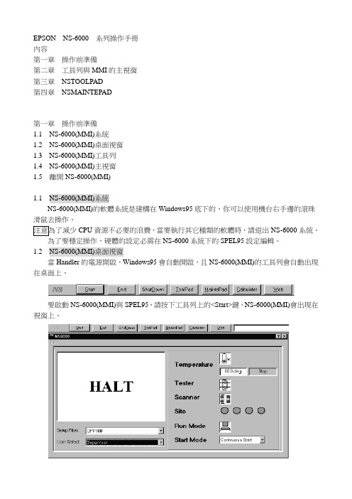
1.2NS-6000(MMI)桌面視窗當Handler的電源開啟,Windows95會自動開啟,且NS-6000(MMI)的工具列會自動出現在桌面上。
要啟動NS-6000(MMI)與SPEL95,請按下工具列上的<Start>鍵,NS-6000(MMI)會出現在視窗上。
如果要讓Counters出現在視窗的右邊,可在<ToolPad>→NSTOOLPAD→<Counter Select>圖示→[Counter Select]的介面。
(溫度顯示會出現在MMI視窗的底部)1.3NS-6000(MMI)工具列如要使用此工具列上所有的按鍵,請讓機台在HALT的狀態下(RUNNING的狀態下只有Calculator可以使用。
按鍵選擇如下:Start:開始執行NS-6000系統End:結束NS-6000系統ShutDown:關機,系統跳到可關機畫面時即可關閉電源。
ToolPad:包含Kits、加熱盤、tray盤、測試設定……等。
MaintePad:運作速度、Offset定位點調整、進階安全設定…..等。
Calculator:計算機。
Web:網路連結。
1.4NS-6000(MMI)主視窗在主視窗中,可以看到系統目前的狀態、一些基本的系統設定。
雷赛BASIC编程手册v2.1
3.2.7 STOP ...............................................................................................................18
3.2.8 AUTO..............................................................................................................18
3.3.1 运算符.............................................................................................................19
3.3.2 ABS.................................................................................................................22
3.2.3 SUB.................................................................................................................17
3.2.4 ON GOSUB ....................................................................................................18
雷赛运动控制器 BASIC 语言编程手册
Version 2.1
雷赛6000系列运动控制器硬件手册V2.0

雷赛6000系列四轴运动控制器硬件手册Version 2.0©Copyright 2011 Shenzhen Leadshine Technology Co.,Ltd.All Rights Reserved.版权说明本手册版权归深圳市雷赛智能控制股份有限公司所有,未经雷赛公司书面许可,任何人不得翻印、翻译和抄袭本手册中的任何内容。
涉及雷赛6000系列控制器软件的详尽资料以及每个函数的介绍和范例,请参阅6000系列控制器软件手册。
本手册中的信息资料仅供参考。
由于改进设计和功能等原因,雷泰公司保留对本资料的最终解释权!内容如有更改,恕不另行通知!调试机器要注意安全!用户必须在机器中设计有效的安全保护装置,在软件中加入出错处理程序。
否则所造成的损失,雷泰公司没有义务或责任对此负责。
目录第一章概述 (4)1.1产品简介 (4)1.2技术指标 (5)1.3典型应用 (5)1.4订货代码 (6)第二章各接口及引脚定义 (7)2.1运动控制器接口分布 (7)2.2接口定义 (8)2.3控制器电源 (15)2.4U盘 (15)第三章接口电路 (16)3.1控制电机的指令脉冲接口电路 (16)3.2原点开关信号接口电路 (17)3.3限位开关信号接口电路 (17)3.4急停信号接口电路 (18)3.5通用数字输入信号接口电路 (18)3.6通用数字输出信号接口电路 (19)3.7ACC37-7480接线板接口电路 (22)3.8PWM输出信号 (24)3.9DA输出信号 (25)第四章运动控制器与典型外设的连接 (27)4.1 与步进电机驱动器连接 (27)4.2 与交流伺服电机驱动器连接 (28)4.3 与接近开关的连接 (28)4.4 与光电开关的连接 (29)4.5 与中间继电器的连接 (29)4.6 疑难问题及解决 (30)第五章运动控制器的安装尺寸 (31)5.1 SMC6480安装尺寸 (31)5.2 SMC6490、PMC6496安装尺寸 (31)第一章概述1.1 产品简介雷赛6000系列运动控制器是雷赛公司自主研发的基于10/100M以太网的通用型运动控制器,可支持多个控制器和PC组成控制网络,网络中控制器的数量没有限制;也可应用于各种需要独立运行的场合。
Bosch Rexroth6000

7
© All rights reserved by Bosch Rexroth AG, even and especially in cases of proprietary rights applications. We also retain sole power of disposal, including all rights relating to copying, transmission and dissemination.
焊接系统结构组成
Electric Drives and Controls
15
© All rights reserved by Bosch Rexroth AG, even and especially in cases of proprietary rights applications. We also retain sole power of disposal, including all rights relating to copying, transmission and dissemination.
Bosch Rexroth 焊接控制面板设备熟悉
漏电检测 仪
控制器PSI 6X00.1xx.L1
空开(欠压保 护功能) 交流接触器
外置24VDC电 源
接线端子排
Electric Drives and Controls
8
© All rights reserved by Bosch Rexroth AG, even and especially in cases of proprietary rights applications. We also retain sole power of disposal, including all rights relating to copying, transmission and dissemination.
6000使用手册中文版
®®SWITCHINGPOWER SUPPLYAUTOMATICTEST SYSTEM6000User’s Manual (中文版)保證書致茂電子股份有限公司秉持"品質第一是責任,客戶滿意是榮譽"之信念,對所製造及銷售之產品自交貨日起一年內,保證正常使用下產生故障或損壞,負責免費修復。
保證期間內,對於下列情形之一者,本公司不負免費修復責任,本公司於修復後依維修情況酌收費用:(1)非本公司或本公司正式授權代理商直接銷售之產品。
(2)因不可抗拒之災變,或可歸責於使用者未遵照操作手冊規定使用或使用人之過失,如操作不當或其他處置造成故障或損壞。
(3)非經本公司同意,擅自拆卸修理或自行改裝或加裝附屬品,造成故障或損壞。
保證期間內,故障或損壞之維修品,使用者應負責運送到本公司或本公司指定之地點,其送達之費用由使用者負擔。
修復完畢後運交使用者(限台灣地區)或其指定地點(限台灣地區)之費用由本公司負擔。
運送期間之保險由使用者自行向保險公司投保。
致茂電子股份有限公司服務專線:(02)2298-3855轉3249傳真電話:(02)2298-3596目錄1. 系統架構 (1)1.1 簡介 (1)1.2 硬體架構 (3)1.2.1 系統控制器─個人電腦及週邊設備 (4)1.2.2 輸入電源供應器 (6)1.2.3 輸出模組─Switcher Analyzer (9)1.2.4 特殊功能模組(Extended Measurement Unit) (10)1.2.5 OVP/UVP電源供應器 (10)1.3 軟體功能 (11)2. 系統安裝 (13)2.1 安裝PowerPro軟體 (13)2.2 硬體的配線與連接 (13)2.2.1 系統的外殼 (13)2.2.2 系統的硬體組成 (14)2.2.3 系統接線及方塊圖 (15)2.2.4 硬體安裝 (16)2.3 電源與接地 (17)2.4 熱氣的排散 (17)2.5 開機前的注意事項 (18)3. 一般性操作 (18)4. 測試功能 (19)4.1 重要訊息 (19)4.2 術語 (20)4.3 各項功能測試說明 (23)4.3.1 輸出入特性測試(INPUT/OUTPUT TEST) (27)4.3.2 動態特性測試(DYNAMIC TEST) (32)4.3.3 同步動態特性測試(SYNC DYNAMIC TEST) (36)4.3.4 負載效應測試(LOAD REGULATION TEST) (37)4.3.5 交叉負載效應測試(CROSS REGULATION TEST) (41)4.3.6 電源效應測試(LINE REGULATION TEST) (42)4.3.7 混合效應測試(COMBINE REGNLATION TEST) (46)4.3.8 開機測試(TURN ON & SEQUENCE TEST) (47)4.3.9 關機測試(HOLD UP & SEQUENCE TEST) (55)4.3.10 過載保護測試(OVER LOAD PROTECTION TEST─OLP) (60)4.3.11 過功率保護測試(OVER POWER PROTECTION TEST-OPP) (65)4.3.12 在線電壓調整測試(HOLD ON ADJUST TEST) (71)4.3.13 外加波形測試(EXTERNAL WA VE TEST) (74)4.3.14 靜態測試(STATIC TEST) (74)4.3.15 附加點時序測試(EXTRA TIMING TEST) (75)4.3.16 測試環境設立功能(SET UP FUNCTION) (80)4.3.17 附加量測點測試(EXTENDED MEASUREMENT TEST) (85)4.3.18 短路測試(SHORT CIRCUIT TEST) (89)4.3.19 過電壓低電壓保護測試(OVP/UVP TEST) (95)4.3.20 總效應測試(TOTAL REGULATION TEST) (102)4.3.21 斷電測試(CYCLE DROPOUT TEST) (107)4.3.22 輸入電壓極限測試(V in RAMP TEST) (111)4.3.23 輸入頻率極限測試( F in RAMP TEST ) (115)4.3.24 輸入電源擾動測試(AC NOISE CARRY THROUGH TEST) (116)4.3.25 同步動態測試2 (SYNC DYNAMIC 2) (120)5. 錯誤或提示訊息及故障排除 (121)5.1 編輯畫面時發生的錯誤或提示訊息 (121)5.2 檔案下載或程式執行時發生的錯誤訊息 (135)1.系統架構1.1簡介Chroma 6000電源供應器自動測試系統(以下簡稱ATS)為一泛用型的電源供應器自動測試系統,可測試AC/DC及DC/DC兩種型態的電源供應器。
R14S R15S 冲压机械手系统 用户使用手册说明书
东莞市西格玛自动化科技股份有限公司R14S/R15S 冲压机械手系统用户使用手册Version 2.0版权说明本手册版权归东莞市西格玛科技股份有限公司所有,未经本公司书面许可,任何人不得翻印、翻译和抄袭本手册中的任何内容。
本手册中的信息资料仅供参考。
由于改进设计和功能等原因,西格玛公司保留对本资料的最终解释权,内容如有更改,恕不另行通知。
软件中加入出错处理程序。
否则所造成的损失,雷赛公司没有义务或责任负责。
目录1.产品概述 (1)1.1 R14S/R15S 运动控制器的特点 (1)1.2 基于R14S/R15S 的冲压机械手系统简介 (2)1.3 订货信息 (2)2.界面及功能介绍 (1)2.1 开机界面 (1)2.2 自动运行界面 (2)2.3 快捷窗口 (4)2.4 参数管理设置界面 (5)2.5 厂商参数设置界面 (6)2.5.1 画面切换 (6)2.5.2 厂商参数-1 (7)2.5.3 厂商参数-2 (8)2.5.4 厂商参数-3 (9)2.6 用户参数设置界面 (12)2.6.1 系统运行工作模式设置 (13)2.6.2 冲压参数设置 (14)2.6.3 取放料参数设置 (14)2.6.4 连线参数设置 (15)2.6.5 取料工具设置 (15)2.7 速度参数设置界面 (15)2.7.1 速度参数设置 (16)2.7.2 手动速度设置 (17)2.8 工作零点界面设置 (17)2.9 软限位设置界面 (18)2.10 手动操作 (19)2.10.1 显示说明 (19)2.10.2 档位切换 (19)2.10.3 操作说明 (19)2.11 文件管理界面 (21)2.11.1 文件管理概述 (21)2.11.2 文件管理操作 (21)2.11.3 系统参数操作 (23)2.12 文件编辑 (24)2.12.1 文件编辑主界面 (24)2.12.2 指令编辑界面 (26)2.13 IO 监控 (28)2.14 帮助界面 (30)3.指令说明 ..................................................................................................3.1 概述 (30)3.1.1 取料 (30)3.1.2 放料 (31)3.1.3 取料等待 (32)3.1.4 放料等待 (33)3.1.5 取料上方 (33)3.1.6 放料上方 (34)3.1.7 取料回上 (34)3.1.8 放料回上 (35)3.1.9 等待输入 (35)3.1.10 端口输出 (36)3.1.11 输入跳转 (37)3.1.12 强制跳转 (38)3.1.13 延时 (38)3.1.14 过渡点 (39)3.1.15 阵列取料 (39)3.1.16 阵列放料 (40)3.1.17 直线插补 (41)4.电气说明 (42)4.1 开孔及安装尺寸 (42)4.2 电柜布局 (43)4.3 触摸屏通信 (43)4.4 控制器外部接口定义 (45)4.5 伺服驱动器和控制器定义 (45)4.6 手摇轮接口定义 (47)5.报警说明 (47)6.指令使用技巧 (49)6.1 空移 (49)6.2 取料等待/放料等待 (49)7.常见问题集合 (49)1.产品概述1.1 R14S/R15S 运动控制器的特点R14S/R15S-IEC 是一款支持IEC61131-3 编程语言标注的高性能独立式运动控制器。
DMC2000硬件手册
DMC2000硬件手册深圳雷赛DMC2000硬件手册.版本1.2第一章概述1.1 产品简介DMC2000系列是基于PCI总线的高性能运动控制卡,可控制多达4个步进或伺服电机。
此系列具有即插即用、最高2.4MHZ脉冲频率、S曲线减振功能、编码器反馈、Z信号精密找零、随时变速等高级功能。
位置指令可用单路脉冲(脉冲+方向)或双路脉冲(CW脉冲+CCW脉冲)方式输出,可以是差分式,也可以是单端式。
如用于伺服控制时,每轴提供了报警(ALM),定位完成(INP),误差清除(OUT3,4,5,6),伺服开启(OUT1,2,7,8)和已准备(INPUT)等五个信号,使用户的接口和编程工作大大简化。
DMC2200可控制1至2个电机作独立或插补运动,DMC2400可控制多达4个电机。
DMC2000系列比ISA总线的DMC200功能更加强大,硬件接口上有一定的相似性,软件指令方面有一定程度的兼容性。
本产品配有WIN95/98/NT/2000下的动态链接库,方便客户编写自己的应用软件,同时提供MOTION2000调试示范软件,可演示此卡功能,方便客户测试控制卡以及电机驱动系统。
1.2 产品特点32位PCI总线,即插即用两轴圆弧和直线插补功能,3轴或4轴直线插补最大输出脉冲频率2.4MPPS 加/减速时间可任意编程脉冲输出模式:脉冲/方向、正向/反向可选T/S型速度曲线可选,非对称加减速最多4轴脉冲和方向输出,控制步进和伺服电机用于增量编码器反馈的28位上/下计数器多轴连续起动/停止可编程中断源全部I/O光隔离,耐2500VRMS电压运动中可改变速度每轴提供原点、索引信号、正负限位开关专用接口手动脉冲输入接口最多支持一个系统12块卡同时工作 Microsoft Windows 应用开发软件, MOTION2000 调试软件每轴具编码器计数和反馈功能DMC2000库和实用程序及Windows 95/98/ NT /2000 DLL1.3 技术指标性能:□控制轴数: 2轴 (DMC2200), 4轴 (DMC2400)□内部参考时钟: 9.8304MHZ□最大脉冲输出频率: 2.4MHZ线性、梯形或S曲线速度驱动方式□位置脉冲设置范围: 0--268,435,455 个脉冲(28位)□斜坡下降设置范围:0--16,777,215□加/减速设置范围: 1--65535(16位)□上/下计数器计数范围:0--268,435,455(28位)或-134217728--+134217727□脉冲速率设置: 0--2.4MPPSI/O信号:□DMC2400的通用I/O口一般是4进4出,软件设置后最多可达12进8出(8个SD输入,4个INPUT输入);DMC2200的通用I/O口一般是2进6出,软件设置后最多可达6进6出(4个SD输入,2个INPUT输入,6个通用OUT输出)。
EXTender 6000系列产品安装手册说明书

Installation Procedure and Pre-Installation Checklistfor the EXTender 6000The Branch Office EXTender 6000 & the PBXGateway EXTender 6000 are simple to install once you have all the requisite cabling, hardware and network capacity in place. To make sure your installation goes smoothly, you should complete the following checklist prior to installing the units. This will be helpful whether you contract out the installation to your equipment provider or a third-party service organization or install the units yourself.This checklist can be used for:•Planning and engineering•Configuration of the Branch Office EXTenderOnce you have completed the checklist, you can give it to the technician who will install and configure your EXTender 6000 units to ensure all the requirements for a successful installation have been met.The basic installation process consists of the following steps:Pre-Installation Steps:1.Determine network type and acquire appropriate network termination devices2.Calculate bandwidth requirements based on number of users and voice compression3.Provision or increase network capacity (if not already present)4.Make sure that PBX/KTS and messaging systems have port capacity for branch users5.Wire remote and switch sites for phones and extended digital ports6.Acquire appropriate cabling from Branch Office EXTenders to network termination devicesInstallation Steps:7.Install and configure units with network termination devices8.Connect the units to phones and switch9.Power on units and let the calling begin!10.Customize user configurations through management interface as desiredBranch Office EXTender 6000 Pre-Installation Checklist Section A: Account ProfileProgram Manager Contact InformationCompany Name:Address:City:Prov./State:Postal/Zip Code: Contact Name:Title:Contact Telephone:Contact Fax:Contact E-mail:Contact Pager/Cell:Switch Site Installation InformationContact:Address:City:Prov./State:Postal/Zip Code: Contact Telephone:Contact Fax:Contact E-mail:Contact Pager/Cell:Remote Site Installation InformationContact:Address:City:Prov./State:Postal/Zip Code: Contact Telephone:Contact Fax:Contact E-mail:Contact Pager/Cell:Installation InformationTarget Installation Date: Lab/Existing Telephone: Technician:Type Of Installation:G Technician-installed G Self-installationSales Contact Information (from whom did you purchase your EXTender 6000?) Company:Location:Sales Rep:Telephone:Sales Engineer:Telephone:Central Office Information (providing your network connectivity)Company:Location:System Engineer Name:Telephone:Account Manager Name:Telephone:Step 1: Network Type and Termination DeviceType of Network:G T1 or Fractional T1 (Complete Section 3.A & 3.1)G ISDN (Complete Section 3.B & 3.1)G Frame Relay (Complete Section 3.A & 3.1)G56/64K Digital Data Service (leased line) (Complete Section 3.C & 3.1)G Ethernet IPG Other: _____________________________Type Of Network Termination Device:G Branch location:Make/Model Number: ____________________G Switch location:Make/Model Number: ____________________G Network is already installedG Network will be installed on: ______________ G Network provider: _______________________ G Network has been tested by: _______________ G Date:__________________________________Network Termination Device providesG Synchronous clear channel connection withG V.35 Interface “or”G RS-232 Interface “or”G V.530 InterfaceG10BaseT Ethernet IP connectionStep 2: Bandwidth RequirementsOne of the most important factors in the success of your EXTender 6000 is to determine the necessary network bandwidth needed for your application. This section will explain how to determine the size of the required bandwidth that will be used in your application of the EXTender 6000 units. Determining the appropriate bandwidth is a function of two factors:G Number of Users (Phones)G Voice Compression for Each UserNumber of UsersThe number of users is the number of simultaneous users (digital PBX phones) that will be extended at any given branch location. Physically, there could be up to eight simultaneous users for one EXTender pair. Statistically, not all users will be on the phones at the same, so you may be able to decrease bandwidth and still maintain high performance.Switch/Remote Bandwidth RequirementsVoice CompressionThe EXTender 6000 deploys voice compression in order to extend multiple users across fewer data channels. The EXTender 6000 supports the following voice compression algorithms: G.711, 32 Kbps ADPCM, 24 Kbps ADPCM and G.729A. Depending on the voice compression algorithm selected, you may need anywhere from 16 Kbps (G.729A), 40 Kbps (ADPCM32) or 72Kbps (G.711) per user.Compression Algorithms and the Corresponding Bandwidth SizeG711ADPCM32ADPCM24G.729ANo Compression32 (40 w/signaling) Kbps24 (32 w/signaling) Kbps8 (16 w/signaling) KbpsUsing the bandwidth management chart below, you can determine the total bandwidth necessary to support your application. If you have excess bandwidth on your network circuit, your network terminating devices could allow you to use that bandwidth to connect to a router or even another EXTender 6000. In order to accomplish this, you must have the multi-port capability on your network service terminating device. For more information on your network terminating devices, please see the Network Terminating Equipment section of the System Administrator’s Guide.Selecting the Proper Voice CompressionThe best voice quality is achieved by using the ADPCM32 compression. However, the maximum quality comes at the expense of the highest utilized bandwidth. The highest degree of voice compression isachieved by using the G.729A. If you are using this algorithm, you will significantly save on the bandwidth and still achieve voice quality that is regarded as near toll. If absolute conversation quality is your goal and bandwidth is not a constraint, you probably want to select ADPCM32. If you are conserving bandwidth, you might employ the G.729A.You can also vary the compression per user. If you have support reps handling sensitive customer calls or people who use the conferencing feature often, you might want to assign the highest quality, ADPCM 32 to those users. Others in the organization, perhaps engineers or accountants, may use the phone much less often and can be assigned G.729A (which is near-toll quality) to conserve bandwidth.If you are using different compression algorithms for each individual user (port), use the following formula to establish your aggregate data bandwidth needs.Number of ports at G.711Number ofports atG.729ANumber ofports atADPCM 24Number ofports atADPCM 32x 72x 16x 32x 40BandwidthRequiredNumber ofDS0’sA+B+C+D= X(Divide by 56or 64 todeterminenumber ofDS0 channelsneeded)* N OTE: If your DS0s on your CSU/DSUs are set up for 56Kbps, use 56 and if they are set up for64Kbps DS0s, use 64.Step 3: Provision or Increase Network CapacityBased on the bandwidth requirements you calculated in Step 2, make sure your network has adequate bandwidth provisioned. You may also want to consider a back-up plan when you calculate your bandwidth and network types. For example, if you are using T1 as your primary network connection on WAN1, you might want to provision an ISDN line for redundancy on WAN2.Line InformationTo assist you in setting up your network termination device (CSU/DSU, MUX, etc.), it will be helpful to record the following information from your service provider and network configuration.Please complete appropriate section in reference to network service being implemented with the Branch Office EXTender and Branch Office Configuration Hardware (section 3.1).3.A T1/FT1 Line Provisioning & Misc. Information3.B ISDN Line Provisioning & Misc. InformationNote: If X from Step 2 is greater than 128Kbps, ISDN service will not provide adequate bandwidth for 8 digital sets functional concurrently. One ISDN 2B+D Circuit can support up to eight (8) digital sets fully functional concurrently with G.729a compression selected for all ports. Or one ISDN 2B+D Circuit could support two (2) Branch Office EXTenders with a total of 16 digital sets but of which only 4 could be concurrently active per BOE on the respective B Channel for a total of 8 sets active concurrently. For this to occur, network service terminating equipment (TA) must have the capacity of two data ports.Port 1:G BOE DataG LAN/WAN Data Physical Interface:G Winchester Female G DB-25 Female Port 2:G BOE DataG LAN/WAN Data Physical Interface:G Winchester Female G DB-25 FemaleISDN Line Provisioning G Both Channels Circuit Switch Voice & Data (CSVD)Switch PBX/KSU Digital Port Cross Connect Date:______ / ______ / ______Remote Digital Station Port Runs & Cross Connect Date:______ / ______ / ______Switch ISDN Network Service Circuit ID:Remote ISDN Network Service Circuit ID:3.C Leased Line Provisioning & Misc. InformationNote: If X from Step 2 is greater than 128Kbps, 56/64K Digital Data Service (DDS) Leased Line will not provide adequate bandwidth for digital set functionality. One DDS Circuit can support up to eight (8) digital sets at the remote location, of which four (4) can be fully functional concurrently with G.729a compression selected for all ports. Two DDS circuits can be provided to the BOE for bandwidth to support the 8 sets concurrently.Port 1:G BOE DataPhysical Interface:G Winchester FemaleG DB-25 FemaleSwitch PBX/KSU Digital Port Cross Connect Date:______ / ______ / ______Remote Digital Station Port Runs & Cross Connect Date:______ / ______ / ______DDS Network Service Circuit ID:3.1 Branch Hardware Configuration InformationSwitch EXTender Name (Optional):Up To 16 Characters BOE #1 _____________________________BOE #2 _____________________________BOE #3 _____________________________BOE #4 _____________________________BOE #5 _____________________________BOE #6 _____________________________BOE #7 _____________________________BOE #8 _____________________________Switch EXTender IP Address (Optional):BOE # 1 ______ . ______ . ______ . ______BOE # 2 ______ . ______ . ______ . ______BOE # 3 ______ . ______ . ______ . ______BOE # 4 ______ . ______ . ______ . ______BOE # 5 ______ . ______ . ______ . ______BOE # 6 ______ . ______ . ______ . ______BOE # 7 ______ . ______ . ______ . ______BOE # 8 ______ . ______ . ______ . ______Switch EXTender IP Address Default Router (Optional):______ . ______ . ______ . ______Switch EXTender IP Subnet Mask (Optional):______ . ______ . ______ . ______IP Address Switch Network Terminating Device (Optional):______ . ______ . ______ . ______Remote EXTender Name (Optional):Up to 16 Characters BOE #1 _____________________________BOE #2 _____________________________BOE #3 _____________________________BOE #4 _____________________________BOE #5 _____________________________BOE #6 _____________________________BOE #7 _____________________________BOE #8 _____________________________Remote EXTender IP Address (Optional):BOE # 1 ______ . ______ . ______ . ______BOE # 2 ______ . ______ . ______ . ______BOE # 3 ______ . ______ . ______ . ______BOE # 4 ______ . ______ . ______ . ______BOE # 5 ______ . ______ . ______ . ______BOE # 6 ______ . ______ . ______ . ______BOE # 7 ______ . ______ . ______ . ______BOE # 8 ______ . ______ . ______ . ______Remote EXTender IP Address Default Router (Optional):______ . ______ . ______ . ______Remote EXTender IP Subnet Mask (Optional):______ . ______ . ______ . ______IP Address Remote Network Terminating Device (Optional):______ . ______ . ______ . ______Step 4: Wire Remote Site for PhonesMake sure that your branch office has been wired for your digital sets, and that you have phones available. We also recommend that you have an analog phone somewhere in your branch for emergencies or back-up (this could be your fax machine).Remote – Block PunchdownG Remote RJ21 (Male) port to punch down block – 110 or 66 (marked)Remote Punchdown1)____ ____2)____ ____3)____ ____4)____ ____5)____ ____6)____ ____7)____ ____8)____ ____Extension (DN) Assigned1)__________2)__________3)__________4)__________5)__________6)__________7)__________8)__________Step 5: Check PBX/KTS Configuration, CapacityMake sure that you have digital ports available on your PBX for each user at the branch office, the ports are programmed in the PBX and punched down to the block, and that your voicemail, unified messaging, ACD and accounting systems have adequate capacity to support your branch users.Switch – PBX Programming – Block PunchdownG Switch digital port setup/functional and RJ21 (Male) port to punch down block – 110 or 66(marked)Switch Digital Shelf/Card/Slot/Port1)____ ____ ____ ____2)____ ____ ____ ____3)____ ____ ____ ____4)____ ____ ____ ____5)____ ____ ____ ____6)____ ____ ____ ____7)____ ____ ____ ____8)____ ____ ____ ____Extension (DN) Assigned1)__________2)__________3)__________4)__________5)__________6)__________7)__________8)__________Step 6: CablingReview this section carefully and make sure that you have the necessary cables before you begin installation. Note: The cables that are included with the EXTender units are the power & RS530 (DB25 male à DB25 female) for both units & the serial cable with remote unit. Other cables and accessories are readily available through a computer supply source or through MCK. Call Sales at 1-888-454-7979 to order your cables.EXTender Cabling & Other InformationSwitch (PBX / KSU Location)G Serial cable for / to management station (Female DB-9 port on BOE)G Ethernet Cable (Optional) – twisted pair (10BaseT) for connectivity to TCP/IP data network hub formanagement capabilities (TelNet)G Cable for connectivity EXTender 6000 (BOE) to Network Terminating Equipment (NTE)G M34 Winchester Male (NTE) à DB25 Female (BOE) “or”G DB25 Male (NTE) à DB25 Female (BOE) “or”G DB25 Male and M34 Adapter à DB25 Female to Winchester MaleG Switch digital line card port punch down to block for cross connect to RJ-21 port on Switch BranchOffice EXTender for digital station ports being extended.Note: MCK recommends that cross connects for digital ports being extended be done to a separate block.DB25 Male to Female cable is included with each Branch EXTender Unit.Remote Branch Site:G Serial cable for / to management stationG Ethernet Cable (Optional) – twisted pair (10BaseT) for connectivity to TCP/IP data network hub formanagement capabilities (TelNet)G Cable for connectivity EXTender 6000 (BOE) to Network Terminating Equipment (NTE)G M34 Winchester Male (NTE) à DB25 Female (BOE) “or”G DB25 Male (NTE) à DB25 Female (BOE) “or”G DB25 Male and M34 Adapter à DB25 Female to Winchester MaleG Station runs to punch down block for cross connect to RJ-21 port on Remote Branch Office EXTenderfor digital station ports being extended.DB25 Male to Female cable is included with each Branch EXTender Unit.Introduction Wiring Info The EXTender 6000 connects to network devices via one or two male DB-25connectors, labeled WAN1 and WAN2.The WAN ports recognize three synchronous protocols;GRS-232 (see figure A for pinouts)GV.35 (see figure B for pinouts)G RS-530 (see figure C for pinouts)Note: The data port of the network terminating device must support one of aboveprotocols operating in a synchronous manner.Figure A through C , lists each pin within the DB-25 connector with the signaldescription and signal/voltage source, using the Electronics Industry Association (EIA)standard.Note: The WAN ports on the back of the EXTender 6000 are DB-25 Male.RJ21 port on the back of the EXTender 6000 is 50-Pin Male.Cables Available From MCKDB-25 Male to DB-25 FemaleG MCK # A-CDB25MF-1M34 Adapters – DB-25 Female to Winchester MaleG MCK # A-ADB25M34Cables Available From Black BoxTelephone: 724-746-5500DB-25 Male to FemaleG Black Box # EVN530-005-MF M34 Adapters – DB-25 Female to Winchester MaleG Black Box # FA059Connector Pinout InformationFigure A . RS-232 Cable PinoutsFigure B. V.35 Cable PinoutsFigure C. RS-530 Cable PinoutsStep 7: Branch Office EXTender 6000 InstallationComplete, step-by-step instructions are available in the System Administrator’s Guide (included with switch unit(s)) and the Quick Installation Guide (included with remote unit(s)). Once all the components are in place, cabling is a simple process.Step 8: Power On!Once the units are cabled to the network device and to the phones and switch and the network is up and running, you are ready to power on. Since the units come pre-configured with default settings (G.729a compression / 384k bandwidth / V.35 protocol), you should be able to place and receive calls immediately.Step 9: Customize ConfigurationMost likely, you will want to customize the configuration to reflect your company’s needs. For example, you can change compression options per user, assign passwords, increase or decrease bandwidth, and customize many other functions. Again, complete instructions for using the management interface are included in the System Administrator’s Guide.。
单回路控制器手册
0 只读 1 读/写
密码值
0~9999
所有操作模式下的参数均可在设置模式下显示
5 5 1 0 99 59 1 1000 0 0 0 0 1 1 10
1 PB=0 时此参数出现 2 ON/OFF 控制时出现 3 随报警类型不同显示参数不同 4 直流输入时出现 5 第二输出作为控制输出时出现 6 PB=0 时出现 7 只有选择通讯选件时出现
微分时间 1
1 秒~99 分 59 秒
死区 1 5 手动积分 1 ON/OFF 控制回差 输出 1 2
-20%~+20% PB1+PB2
0%~100% 单 输 出 100%~+100% 双输出
ON/OFF 控制回差 输出 2 2
0.1%~10% 满量程
ON/OFF 控制回差 双输出 2 5
设定值上限
9
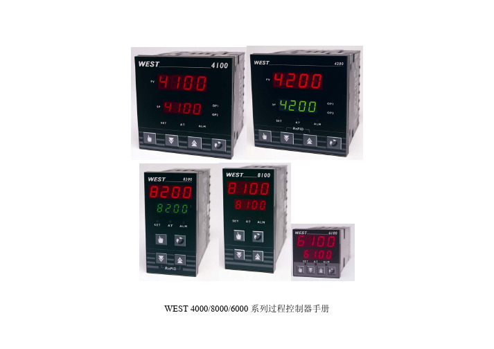
WEST4000/8000/6000 系列产品手册
图 2-1 比例带及死区
10
WEST4000/8000/6000 系列产品手册
2.2.20 输出 1 控制周期 取决于所控制的对象的特性及输出 1 的种类 对于继电器输出 其控制周 期应尽可能长以确保继电器的使用寿命 在保证控制品质的前提下 对 于固态继电器其控制周期可以相对短一些 使其更适合于控制一些快速变 化的过程 如压力或流量 PB1=0 或直流输出时不适用 2.2.21 输出 2 控制周期 同输出 1 控制周期 2.2.22 过程高报警 1 值 过程值达到或超过此数值时报警 1 报警 报警 1 设置为过程高报警时适用 2.2.23 过程低报警 1 值 过程值达到或低于此数值时报警 1 报警 报警 1 设置为过程低报警时适用 2.2.24 带报警 1 值 定义一以设定值为中心的区域 当过程值离开此区域时 报警 1 报警 报 警 1 设置为带报警时适用 2.2.25 偏差报警 1 值
雷赛智能 ICL42-RS06 RS485一体式步进电机产品用户手册说明书

智能一体式步进电机ICL42-RS06(RS485)用户手册(版本:V1.0)Array◆非常感谢您本次购买雷赛产品◆使用前请详细阅读此说明书,正确使用该产品◆请妥善保管此说明书1前言首先感谢您购买使用雷赛公司支持RS485网络的总线型智能一体式步进电机产品。
智能一体式电机系列是雷赛在高性能数字驱动器基础上增加了总线通讯和单轴控制功能的产品。
总线通讯采用RS485网络接口,基于Modbus RTU总线协议,实现步进系统的实时控制与数据传输。
该产品还内部集成控制器,支持16段位置表功能(PR),在对驱动器编程后,通过IO、触摸屏或者RS485通信触发后即可运转,具有使用简单、稳定可靠、功能丰富等特点。
本手册仅介绍智能一体式步进步进电机的规格与应用。
若对使用有所疑惑,请咨询我公司的技术人员以获得帮助。
感谢您选用深圳市雷赛智能控制股份有限公司的智能一体系列步进电机驱动产品,本手册提供了使用该产品的所需知识及注意事项。
操作不当可能引起意外事故,在使用本产品之前,请务必仔细阅读本说明书由于产品的改进,手册内容可能变更,恕不另行通知。
用户对产品的任何改动我厂将不承担任何责任,产品的保修单将因此作废。
阅读本手册时,请特别注意以下提示:警告●只有技术人员才能安装,调试或维护本产品●确保线路连接正确,方可通电测试●错误的电压或电源极性可能会损坏驱动器或造成其他事故目录前言 (1)目录 (2)第一章概述 (3)1.1产品简介 (3)1.2到货检查 (6)1.3产品型号 (7)第二章安装 (8)2.1储存和安装环境 (8)2.2驱动器的安装 (8)第三章接口规格 (10)3.1典型配线图 (10)3.2端子及拨码说明 (10)3.2.1电源及控制信号端子 (11)3.2.2RS485总线接口端子 (11)3.2.3拨码开关 (11)第四章Modbus RTU (13)4.1通讯规格 (13)4.2功能码 (14)4.2.1读取N个数据0x03 (14)4.2.2写入单个数据0x06 (14)4.2.3写入多个数据0x10(略) (15)4.3Modbus RTU参数地址 (15)4.3.1驱动器基本参数 (15)4.3.2状态监控参数 (17)4.3.3辅助功能参数 (17)4.3.4输入输出功能配置 (17)4.4错误处理 (18)4.4.1通讯错误码 (18)4.4.2报警信息参数 (19)4.4.3LED显示及故障处理 (19)第五章PR功能介绍 (20)5.1PR主要功能 (20)5.2回零/回原点 (21)5.3限位、JOG和急停功能 (24)5.4触发方式 (26)5.5触发路径 (27)5.6多段PR路径IO触发举例(暂不支持) (30)第六章上位机软件介绍 (31)6.1软件基本操作 (31)6.2PR功能软件操作 (33)6.3485通讯测试案例 (35)附录1线缆配件选型 (39)附录2通讯线接线制作 (40)附录3保修及售后服务 (42)附录4485&PR参数总表 (43)第一章概述1.1产品简介ICL42-RS系列是雷赛自主研制的全数字智能一体式步进电机产品。
SMC606冲压机械手系统说明书
雷赛SMC606冲压机械手系统用户使用手册Version©Copyright 2015 Leadshine Technology Co., Ltd.All Rights Reserved.版权说明本手册版权归深圳市雷赛智能控制股份有限公司所有,未经本公司书面许可,任何人不得翻印、翻译和抄袭本手册中的任何内容。
本手册中的信息资料仅供参考。
由于改进设计和功能等原因,雷赛公司保留对本资料的最终解释权,内容如有更改,恕不另行通知。
调试机器要注意安全!用户必须在机器中设计有效的安全保护装置,在软件中加入出错处理程序。
否则所造成的损失,雷赛公司没有义务或责任负责。
目录第1章产品概述 (1)SMC606运动控制器的特点 (1)基于SMC606的冲压机械手系统简介 (2)订货信息 (2)主界面功能介绍 (3)第2章参数设置 (4)速度设置 (5)厂商设置 (6)工作零点设置 (9)密码设置 (10)软件限位设置 (11)阵列设置 (11)堆垛设置 (13)其他设置 (14)第3章手动操作 (15)点动操作 (15)定位操作 (15)手轮操作 (16)第4章程序编辑 (17)文件存取 (17)固定点编程 (19)自定义文件编辑 (20)第5章自动运行 (24)功能介绍 (24)报警提示 (26)第6章联线测试 (27)功能介绍 (27)第7章监控界面 (28)通用输入口监控 (28)专用输入口监控 (29)通用输出口监控 (29)报警记录显示 (30)附录 (31)附录1 SMC606接口端子定义表 (31)附录2 SMC606硬件接线说明 (33)附录3 常见问题解决方法 (34)附录4 SMC606与雷赛伺服接口定义 (35)第1章产品概述SMC606运动控制器的特点SMC606-IEC是一款支持IEC61131-3编程语言标注的高性能独立式运动控制器。
该控制器在处理大量数据计算功能时,还能处理不同的外设数据交换。
雷赛智能ACS606交流伺服驱动器使用说明书
深圳市雷赛智能控制股份有限公司地 址:深圳市南山区登良路25号天安南油工业区二座三楼邮 编:518052线)Email:***************网 址:上海办事处北京办事处地 址:上海市淞江区九亭镇九新公路 地 址:北京市朝阳门广渠门外大街8号 76号嘉和阳光大厦9楼优士阁B座308室美国雷赛科技公司 香港雷赛科技公司Address: 630Parkland Dive 地 址:沙田火炭山尾街 31-41号 Rochester Hills, Mi48307 USA 华乐工业中心 E 座 9 字楼 3 室 Tel:1-248-608-6388 电 话:852-2952 9114852-2952 9395ACS606数字交流伺服驱动器使用说明书版权所有不得翻印【使用前请仔细阅读本手册,以免损坏驱动器】深圳市雷赛智能控制股份有限公司目 录前言 (2)概述 (5)一. 技术特点 (5)二. 应用领域 (5)三.技术指标 (6)1.技术参数 (6)2.使用环境及参数 (6)3.机械安装尺寸 (6)端口定义与接线 (8)一.端口定义 (8)1.电源输入端口 (8)2.电机连接端口 (8)3.数字控制信号端口 (8)4.编码器及霍尔反馈信号输入端口 (8)5.RS232通信端口 (9)二. 控制信号应用接线 (9)伺服系统安装与调试 (11)一.准备工作 (11)二.调试伺服参数 (11)1.输入模式设置 (11)2.电流环调节 (13)3.位置环调节 (13)三. 指示灯及故障判断 (15)四. 控制信号典型接线图 (16)1电话:*************(20线)网址:前 言感谢选用深圳市雷赛智能控制股份有限公司ACS系列交流伺服驱动器。
本手册阐述了ACS606系列交流伺服驱动器(50W~400W范围)的安装、调试、维护、运行等方面。
使用前,请认真阅读本手册,熟知本产品的安全注意事项。
本手册,因产品改进、规格、版本变更等原因,将会适当改动,本公司将不另行通知。
leadshine 交流伺服驱动器 L6E伺服系统功能手册说明书

交流伺服驱动器L6E伺服系统功能手册◆非常感谢您本次购买雷赛产品◆使用前请详细阅读此说明书,正确使用产品◆请妥善保管此说明书前言L6E系列伺服手册构成L6E系列伺服采用EtherCAT总线技术,为利于使用人员快速了解和使用L6E伺服产品及EtherCA T总线技术,L6E手册目前分2大部分,分别介绍L6E系列伺服、EtherCAT总线技术,介绍如下:A、《L6E伺服系统EtherCAT通讯功能手册》主要说明EtherCA T通讯原理及功能B、《L6E伺服系统功能手册》主要说明L6E伺服驱动器所包含的功能以及关联参数等详情手册适用对象●使用L6E伺服构建EtherCAT控制系统的开发工程师●为L6E伺服构建的设备提供支持服务的技术工程师L6E系列手册内容由浅入深,望用户可以层层阅读以便更快更好的使用L6E伺服驱动器;为利于使用人员从众多的伺服功能快速找到自己需要的功能,手册增加功能导引。
感谢您选用深圳市雷赛智能控制股份有限公司L6E系列交流伺服系统。
本手册提供了使用本系统所需知识及注意事项。
由于产品的改进,手册内容可能变更,恕不另行通知。
用户对产品的任何改动我司将不承担任何责任,产品的保修单将因此作废前言 ................................................................................................................................................ i i L6E系列伺服手册构成............................................................................................................. i i 手册适用对象............................................................................................................................. i i L6E系列伺服功能导引. (viii)第一章概述 (1)1.1 产品简介 (1)1.2 到货检查 (2)1.3 产品外观 (5)第二章安装 02.1储存和安装环境 02.2 伺服驱动器安装 02.2.1驱动器尺寸 (1)2.2.2安装方法 (2)2.3 伺服电机安装 (3)2.3.1 伺服电机尺寸 (3)2.3.2 安装方法 (6)第三章接口规格 (8)3.1 标准接线 (8)3.1.1配线 (8)3.1.2总线伺服配线图 (10)3.2 驱动器各端子说明 (11)3.2.1控制信号端子-CN1 (11)3.2.2编码器反馈信号端子-CN2 (12)3.2.3 EtherCAT通讯端子-CN3 (13)3.2.4 RS232通讯端子-CN4 (13)3.2.5 USB通讯端子-CN5 (14)3.2.6 主电源输入端子 (14)3.2.7 控制电源端子 (14)3.3 I/O接口原理及功能参数 (15)3.3.1 IO输入 (15)3.3.2 IO输出 (17)第四章显示与操作 (19)4.1面板显示和面板操作 (19)4.1.1概述 (19)4.1.2面板操作流程图 (20)4.1.3驱动器运行数据监视 (21)4.1.4 辅助功能 (24)4.1.5 参数保存 (26)4.1.6异常报警 (26)4.2运行前准备 (27)4.3 面板试运行 (27)4.4 总线运行须知 (28)4.4.1工作模式 (28)4.4.2 必要配置 (29)第五章功能使用 (30)5.1 位置控制 (30)5.1.1 旋转方向设定 (31)5.1.2 PP/CSP/HM指令输入处理 (31)5.1.3 软限位 (32)5.1.4 电子齿轮 (32)5.1.5指令位置滤波 (33)5.1.6 位置定位完成信号INP输出 (34)5.2 速度控制 (36)5.2.1 旋转方向设定 (36)5.2.2 PV/CSV指令输入处理 (37)5.2.3速度指令加减速功能 (37)5.2.4 速度到达信号A T-SPEED输出 (38)5.2.5 速度一致信号V-COIN输出 (39)5.2.6 零速钳位功能 (40)5.3 转矩控制 (41)5.3.1 旋转方向设定 (41)5.3.2 PT/CST指令输入处理 (42)5.3.3速度限制功能 (43)5.4 增益调整功能 (44)5.5 惯量识别功能 (50)5.6 陷波器功能 (52)5.7 前馈功能 (54)5.8 第三增益切换功能 (55)5.9 摩擦转矩补偿功能 (57)5.10 EtherCAT从站别名设定 (57)5.11 再生电阻设定 (57)5.12 安全功能 (59)5.12.1 电机最高转速限制功能 (59)5.12.2 外部制动器解除信号BRK-OFF输出功能 (59)5.12.3 伺服关闭时顺序 (60)5.12.4 转矩限制功能(TL-SEL) (60)5.12.5 报警后立即停止时间 (61)5.12.6 紧急停止功能 (61)5.13 其他功能 (62)5.13.1 零速度输出(ZSP) (62)5.13.2 位置偏差清零(CL) (62)5.13.3 位置指令禁止输入(INH) (62)5.13.4 位置单位选择 (63)5.13.5 到位信号延迟时间 (63)第六章时序图 (64)6.1 上电时序图 (64)6.2 故障时序图 (65)第七章报警与处理 (66)7.1 报警一览表 (66)7.1.1 伺服驱动报警 (66)7.1.2 EtherCAT通讯报警 (67)7.2 伺服驱动报警处理方法 (69)7.2.1 报警分析 (69)7.2.2 报警关联参数 (75)7.2.3 报警清除 (76)第八章产品规格 (78)8.1驱动器技术规格 (78)8.2 伺服电机规格 (79)8.3 应用建议 (79)附录1参数汇总表 (81)附录2原点方法 (84)L6E系列伺服功能导引第一章概述1.1 产品简介L6E系列交流伺服系统是深圳市雷赛智能控制股份有限公司自主研制的全数字总线式交流伺服系统,基于ETG COE + CANopen DSP402协议,可与支持此标准协议的控制器/驱动器无缝连接。
TC-6000系列组件兼容性指南说明书
TC-6000 SeriesComponent Compatibility GuideA list of peripheral components suitable for use with the TC-6000 series of computers2016/07/05 Version 2.0© 2016 Moxa Inc. All rights reserved.Copyright Notice©2016 Moxa Inc.All rights reserved.TrademarksThe MOXA logo is a registered trademark of Moxa Inc.All other trademarks or registered marks in this manual belong to their respective manufacturers.DisclaimerInformation in this document is subject to change without notice and does not represent a commitment on the part of Moxa.Moxa provides this document as is, without warranty of any kind, either expressed or implied, including, but not limited to, its particular purpose. Moxa reserves the right to make improvements and/or changes to this manual, or to the products and/or the programs described in this manual, at any time.Information provided in this manual is intended to be accurate and reliable. However, Moxa assumes no responsibility for its use, or for any infringements on the rights of third parties that may result from its use.This document might contain unintentional technical or typographical errors. Changes are periodically made to the information herein to correct such errors, and these changes are incorporated into new editions of the publication.Technical Support Contact Information/supportMoxa AmericasToll-free: 1-888-669-2872 Tel: +1-714-528-6777 Fax: +1-714-528-6778 Moxa China (Shanghai office) Toll-free: 800-820-5036Tel: +86-21-5258-9955Fax: +86-21-5258-5505Moxa EuropeTel: +49-89-3 70 03 99-0 Fax: +49-89-3 70 03 99-99 Moxa Asia-Pacific Tel: +886-2-8919-1230 Fax: +886-2-8919-1231Moxa IndiaTel: +91-80-4172-9088 Fax: +91-80-4132-10451. IntroductionThis document lists hardware components that are proven to provide the performance listed in the specification when used with the Moxa TC-6000 series of embedded computers, or computers that share basic design features with the TC-6000 series. Moxa computers come with multiple peripheral options and are engineered to work with components having different hardware specifications. This flexibility could sometimes lead to compatibility issues. When used with the TC-6000 series of embedded computers, peripherals from one manufacturer may not work as well as the ones made by another manufacturer. Moxa provides this list of TC-6000 series-compatible components, so that users can be certain of a reliable performance from the TC-6000 series, when used with the components listed in this document.2. Testing MethodsTo validate that a component meets the Moxa standards for quality and performance, the following five key compatibility tests are run:•Ambient temperature burn-in•Low temperature hard start•Heat/humidity burn-in•Cyclic high-low temperature burn-in•Vibration testAmbient Temperature Burn-InThe component is mounted on to a TC-6000 computer and put through a series of stress tests at an ambient temperature of around 25˚C, for a specified period of time. The duration of the test is determined based on the class of peripherals being tested.Low Temperature Hard StartThe component is mounted on to an unpowered TC-6000 computer and then the system is booted up at an extremely low temperature. The designated low temperature value depends on the computer model being tested.Heat/Humidity Burn-InThe component is mounted on to a TC-6000 computer, placed in a temperature- andhumidity-controlled enclosure, and then put through the burn-in test for a specified period of time. The temperature, humidity, and time targets vary depending on the specification of the computer model used in the test.Cyclic High-Low Temperature Burn-InThe component is mounted on to a TC-6000 computer, placed in a temperature controlled enclosure, and then put through the burn-in test wherein the temperature is cyclically varied from very high to very low and back again, over a specified period of time. The target temperature range and the duration of the test can vary depending on the specification of the computer model used in the test.Vibration TestThe component is mounted on to a TC-6000 computer that is bound inside an electromagnetic vibrator, and then put through random vibration tests along three orthogonal axes: longitudinal, transverse, and vertical. The vibration tests are compliant with the EN50155/IEC61373 vibration standards.3. Storage EnduranceStorage media, such as SSDs, CF cards, SD cards, Disk on Module, and Cfast, are composed of different electrical components. The main electrical components in these storage media, the NAND-flash memory and NAND-flash controller, impact the storage endurance and lifespan of the storage media.NAND-Flash Memory EnduranceNAND-flash memories have a limit on the number of times they can be programmed and erased (P/E). The P/E cycle as well as the erase count of a NAND-flash memory can be used to determine this limit. For example, an SLC (single-level cell) flash memory has a 60,000 P/E cycle, an MLC (multi-level cell) flash memory has a 3,000 P/E cycle, and TLC NAND flash memories have P/E cycle values up to 1,000. Each flash memory type has a different endurance level, which is why the storage lifespan is based on the flash memory type. Storage that uses SLC type flash memory could have the best endurance level compared with the MLC type storage. SLC storage usually comes with a 5-year OEM warranty (the actual warranty period depends on the original manufacturer). MLC storage only comes with a 1- to 3-year warranty. The major differences between SLC and MLC are: (a) The SLC NAND flash has a lifespan that is around 20 times that of an MLC, and (b) The price can differ by a factor of 4 to 5. The SLC type of storage is recommended for systems that are expected to have high reliability, and for applications that need to frequently write data to a storage medium.Terabytes Written (TBW)TBW is the unit used to evaluate SSD endurance. In actual applications, storage is used for routine operations and data access. Therefore the physical P/E cycle is not appropriate for describing thetotal rewritable data capacity result. For these reasons, Joint Electron Device Engineering Council (JEDEC) has defined a standard for SSD endurance evaluation called JESD218, which uses TBW to measure the endurance of the storage memory. By referring to this TBW value, users can easily estimate the storage specification and select a suitable storage for real-life use cases. For example, when routine operations need a maximum of 20 GB and the expected storage lifespan is 3 years, the total rewritable data demand would be 21.9 TBW (20 GB x 365 x 3). In this case, a storage that has more than 21.9 TBW will meet the requirement. We recommend selecting a storage media with a TBW that is greater than the calculated value.4. Declaration for Liability ExclusionThe specifications, warranty terms, and liability of items listed in this guide are the sole responsibility of the original manufacturers. Moxa does not take any responsibility in this regard. Please visit the manufacturers’ official websites for up-to-date product information before purchasing the components.5. Compatible ComponentsPeripheral components that have been tested and found suitable for use with the TC-6000 series of computers are listed in this section. The following table lists the Test Codes and their descriptions:Test Code DescriptionA The component has passed the ambient temperature verification testB The component has passed the low temperature verification testC The component has passed the heat/humidity verification testD The component has passed the cyclic high-low temperature verification testE The component has not been tested, but is similar to another component that has been tested in terms of its material and design.F The component has passed the vibration verification testDRAMVendor MemorySize Moxa’s PN Vendor’s PN Interface Chip Brand Speed Test Codes Apacer 2 GB N/A 75.A83E4.G010C DDR3 Micron 1600 MHz ADSL 2 GB 1352110022011 D3SS56081XH18AC DDR3 Samsung 1066 MHz B, C, D DSL 2 GB 135********A1 D3SP56081XH15BBI DDR3 ProMOS 1333 MHz B, C, D DSL 4 GB 1352110042070 D3SH56082XH15AB DDR3 Hynix 1333 MHz B, C, D InnoDisk 2 GB N/A M3SP-2GHJCI0C-D DDR3 Hynix 1600 MHz B, C, D InnoDisk 2 GB N/A M3SW-2GHJCC0C-E DDR3 Hynix 1600 MHz B, C, DCFVendor StorageSize Moxa’s PN Vendor’s PN Flash MemoryBrandFlashMemorySpecController Firmware Warranty WarrantyExclusionTestCodesInnoDisk 8 GB 1352010082115 DC1M-08GD71AW1QB N/A SLC N/A N/A 5 years Endurance >60,000 B, C, D Memoright 1 GB N/A MRCFM2A001GB6C1IA0 Samsung SLC SMI2232 K1124 5 years N/A E Memoright 2 GB N/A MRCFM2A002GB8C1IA0 Samsung SLC SMI2232 K1124 5 years N/A E Memoright 4 GB N/A MRCFM2A004GB0C1IA0 Samsung SLC SM2232 K1124 5 years N/A E Memoright 8 GB N/A MRCFM2A008GB0C1IA0 Samsung SLC SM2232 K1124 5 years N/A B, C, D Memoright 16 GB N/A MRCFM2A016GN2C1IA0 Samsung SLC SM2232 K0407 5 years N/A B, C, D Transcend 128 MB N/A TS128MCF200I Samsung MLC SM2232AD N/A 2 years N/A E Transcend 256 MB N/A TS256MCF200I Samsung MLC SM2232AD N/A 2 years N/A E Transcend 512 MB N/A TS512MCF200I Samsung MLC SM2232AD N/A 2 years N/A E Transcend 1 GB N/A TS1GCF133 SanDisk/ Micron MLC SM2232AD N/A 2 years N/A E Transcend 1 GB N/A TS1GCF200I Samsung MLC SM2232AD N/A 2 years N/A E Transcend 2 GB N/A TS2GCF133 SanDisk/ Micron MLC SM2232AD N/A 2 years N/A E Transcend 2 GB N/A TS2GCF200I Samsung MLC SM2232AD N/A 2 years N/A E Transcend 4 GB N/A TS4GCF133 SanDisk/ Micron MLC SM2232AD N/A 2 years N/A E Transcend 4 GB N/A TS4GCF200I Samsung MLC SM2232AD N/A 2 years N/A A Transcend 8 GB N/A TS8GCF400 SanDisk/ Micron MLC SM2236AC N/A 2 years N/A E Transcend 8 GB N/A TS8GCF133 SanDisk/ Micron MLC SM2232AD N/A 2 years N/A E Transcend 8 GB N/A TS8GCF200I Samsung MLC SM2232AD N/A 2 years N/A E Transcend 16 GB N/A TS16GCF1000 SanDisk/ Micron MLC SM2232ENAC N/A 2 years N/A E Transcend 16 GB N/A TS16GCF400 SanDisk/ Micron MLC SM2236AC N/A 2 years N/A E Transcend 16 GB N/A TS16GCF133 SanDisk/ Micron MLC SM2232AD N/A 2 years N/A E Transcend 16 GB N/A TS16GCF200I Samsung MLC SM2232AD N/A 2 years N/A E Transcend 32 GB N/A TS32GCF1000 SanDisk/ Micron MLC SM2236AC N/A 2 years N/A A Transcend 32 GB N/A TS32GCF400 SanDisk/ Micron MLC SM2236AC N/A 2 years N/A A Transcend 32 GB N/A TS32GCF133 SanDisk/ Micron MLC SM2232AD N/A 2 years N/A E Transcend 32 GB N/A TS32GCF200I Samsung MLC SM2232AD N/A 2 years N/A ASSDVendor StorageSize Moxa’sPN Vendor’s PNFlashMemoryBrandFlashMemorySpecController Firmware Warranty WarrantyExclusionTestCodesApacer 64 GB N/A AP64GAS510SB N/A MLC N/A N/A 2 years Endurance > 3,000 A Transcend 16 GB N/A TS16GSSD500 Samsung SLC JM616 120820 2 years N/A E Transcend 32 GB N/A TS32GSSD500 Samsung SLC JM616 120820 2 years N/A E Transcend 64 GB N/A TS64GSSD320 SanDisk/ Micron MLC SF2281 N/A 2 years N/A E Transcend 64 GB N/A TS64GSSD500 Samsung SLC JM616 120820 2 years N/A A Transcend 128 GB N/A TS128GSSD320 SanDisk/ Micron MLC SF2281 N/A 2 years N/A E Transcend 256 GB N/A TS256GSSD320 SanDisk/ Micron MLC SF2281 N/A 2 years N/A AHDDVendor Size Moxa’s PN Vendor’s PN Controller Firmware Test Codes HGST 500 GB N/A HTS725050A7E630 / 0J38075 N/A N/A A HGST 640 GB N/A HTS541064A9E680 N/A N/A E HGST 750 GB N/A HTS541075A9E680 N/A N/A E HGST 1 TB N/A HCC541010A9E680 N/A N/A A HGST 1 TB N/A HTS541010A9E680 N/A N/A A,F HGST 1 TB N/A HTS721010A9E630 / 0J22423 N/A N/A A HGST 1 TB N/A HTS541010A9E680 N/A N/A F HGST 1 TB N/A HTS541010A9E650 N/A N/A A HGST 1.5 TB N/A HTS541515A9E630 N/A N/A F Samsung 2 TB N/A ST2000LM003 N/A N/A A Toshiba500 GB N/A MQ01ABD050 N/A N/A E Toshiba640 GB N/A MQ01ABD064 N/A N/A E Toshiba750 GB N/A MQ01ABD075 N/A N/A E Toshiba 1 TB N/A MQ01ABD100 N/A N/A F WD 500 GB N/A WD5000LUCT N/A N/A E WD 750 GB N/A WD7500BFCX N/A N/A E WD 750 GB N/A WD7500BPKT N/A N/A A WD 1 TB N/A WD10JUCT N/A N/A A, F WD 1 TB N/A WD10JPVT N/A N/A A WD 1 TB N/A WD10SPCX N/A N/A A WD 1 TB N/A WD10JFCX N/A N/A F。
- 1、下载文档前请自行甄别文档内容的完整性,平台不提供额外的编辑、内容补充、找答案等附加服务。
- 2、"仅部分预览"的文档,不可在线预览部分如存在完整性等问题,可反馈申请退款(可完整预览的文档不适用该条件!)。
- 3、如文档侵犯您的权益,请联系客服反馈,我们会尽快为您处理(人工客服工作时间:9:00-18:30)。
雷赛6000系列四轴运动控制器硬件手册Version 2.0©Copyright 2011 Shenzhen Leadshine Technology Co.,Ltd.All Rights Reserved.版权说明本手册版权归深圳市雷赛智能控制股份有限公司所有,未经雷赛公司书面许可,任何人不得翻印、翻译和抄袭本手册中的任何内容。
涉及雷赛6000系列控制器软件的详尽资料以及每个函数的介绍和范例,请参阅6000系列控制器软件手册。
本手册中的信息资料仅供参考。
由于改进设计和功能等原因,雷泰公司保留对本资料的最终解释权!内容如有更改,恕不另行通知!调试机器要注意安全!用户必须在机器中设计有效的安全保护装置,在软件中加入出错处理程序。
否则所造成的损失,雷泰公司没有义务或责任对此负责。
目录第一章概述 (4)1.1产品简介 (4)1.2技术指标 (5)1.3典型应用 (5)1.4订货代码 (6)第二章各接口及引脚定义 (7)2.1运动控制器接口分布 (7)2.2接口定义 (8)2.3控制器电源 (15)2.4U盘 (15)第三章接口电路 (16)3.1控制电机的指令脉冲接口电路 (16)3.2原点开关信号接口电路 (17)3.3限位开关信号接口电路 (17)3.4急停信号接口电路 (18)3.5通用数字输入信号接口电路 (18)3.6通用数字输出信号接口电路 (19)3.7ACC37-7480接线板接口电路 (22)3.8PWM输出信号 (24)3.9DA输出信号 (25)第四章运动控制器与典型外设的连接 (27)4.1 与步进电机驱动器连接 (27)4.2 与交流伺服电机驱动器连接 (28)4.3 与接近开关的连接 (28)4.4 与光电开关的连接 (29)4.5 与中间继电器的连接 (29)4.6 疑难问题及解决 (30)第五章运动控制器的安装尺寸 (31)5.1 SMC6480安装尺寸 (31)5.2 SMC6490、PMC6496安装尺寸 (31)第一章概述1.1 产品简介雷赛6000系列运动控制器是雷赛公司自主研发的基于10/100M以太网的通用型运动控制器,可支持多个控制器和PC组成控制网络,网络中控制器的数量没有限制;也可应用于各种需要独立运行的场合。
雷赛6000系列运动控制器基于嵌入式处理器和FPGA的硬件结构,插补算法、脉冲信号的产生及加速和减速控制、I/O信号的检测处理,均由硬件和固件实现,确保了运动控制高速、高精度及系统稳定。
该系列控制器可控制4个步进或伺服电机,具有最高5MHz脉冲频率、四轴直线插补、两轴圆弧插补、连续曲线插补、S形曲线速度控制等高级功能。
通过简单的编程即可开发出稳定可靠的高性能连续轨迹运动控制系统。
雷赛6000系列运动控制器结构框图如1-1所示。
图1-1 雷赛6000系列运动控制器构框图除了4个电机控制端口外,还提供了丰富的I/O接口和通讯接口:光电隔离I/O接口、扩展I/O接口、D/A输出、PWM输出、编码器接口、手摇脉冲发生器接口。
1个网络接口、2个串行口,可通过网口或串口与PC机通信;同时还可以通过串口连接其它设备,如:手持编程器、触摸屏、PLC等。
可通过U盘接口用U盘方便地存储文件和参数。
Flash用于存储用户程序、铁电存储器用于参数的掉电保存。
1.2 技术指标雷赛6000系列运动控制器目前有3种型号:SMC6480、SMC6490、PMC6496。
其硬件结构基本相同,局部功能有所差异。
详细技术指标见表1-1。
表1-1 雷赛6000系列运动控制器技术指标1.3 典型应用雷赛6000系列运动控制器已广泛应用于各行各业自动化设备中。
主要设备有:∙电子产品装配、测量设备∙半导体、LCD生产设备∙激光加工设备∙生物、医学自动采样、处理设备∙特种数控机床∙机器视觉及自动检测设备∙工业机器人∙其它控制步进电机、伺服电机的自动化设备1.4 订货代码表1-3 配件型号第二章 各接口及引脚定义2.1 运动控制器接口分布1. SMC6480运动控制器接口分布SMC6480的电机接口J21、I/O 接口J11、D/A 接口、2个串口、扩展I/O 口、电平设置开关,以及网口、U 盘口、电源、指示灯的分布如图2-1所示。
图2-1 SMC6480接口分布图2. SMC6490、PMC6496运动控制器接口分布SMC6490、PMC6496的电机接口J21、I/O 接口J11、2个串口、1个手轮接口、扩展I/O 口、编码器接口、电平设置开关,以及网口、U 盘口、电源、指示灯的分布如图2-2所示。
注意:1、电源请接直流24V ,且注意正负极。
2、如果网络接口连接交换机或者HUB ,请用直连网线;如果是跟PC 机直连,请用交叉网线。
3、使用各接口前,请详细阅读各接口的定义以及接口电路图。
4、网口、U 盘口、扩展IO 接口、SMC6480电平设置开关、SMC6490和PMC6496编码器接口布置在控制器两侧,在图2-1、图2-2中以虚线框表示。
I N 1 I N 2 I N 3 I N 4 I N 5 I N 6 I N 7 I N 8 I N 9 I N 10 I N 11 I N 12 I N 13 I N 14 I N 15 I N 16 O U T 1 O U T 2 O U T 3 O U T 4 O U T 5 O U T 6 O U T 7 O U T 8 P W M 1 P W M 2 V D D E G N D E G N D E G N D E G N D E G N DE G N D E G N D E G N D O R G U O R G Z O R G Y O R G X E L U - E L U + E L Z - E L Z + E L Y - E L Y + E L X - E L X + +5V D I R 4- D I R 4+ P U L 4- P U L 4+ D I R 3- D I R 3+ P U L 3- P U L 3+ D I R 2- D I R 2+ P U L 2- P U L 2+ D I R 1- D I R 1+ P U L 1- P U L 1+·图2-2 SMC6490、PMC6496接口分布图2.2 接口定义SMC6480、SMC6490和PMC6496运动控制器的电源输入口定义如表2-1所示;电机接口J21定义如表2-2所示;I/O 接口J11定义如表2-3所示;扩展I/O 接口JPIO 的定义如表2-4所示;串行口COM1、COM2的接口定义如表2-5所示;电平设置拨码开关定义如表2-6所示。
SMC6480运动控制器的急停信号输入口定义如表2-7所示;D/A 模拟量输出口定义如表2-8所示。
SMC6490和PMC6496运动控制器的编码器接口ENCODER 定义如表2-9所示;手摇脉冲发生器输入口定义如表2-10所示。
表2-1 SMC6480、SMC6490和PMC6496电源输入口定义I N 1 I N 2 I N 3 I N 4 I N 5 I N 6 I N 7 I N 8 I N 9 I N 10 I N 11 I N 12 I N 13 I N 14 I N 15 I N 16 O U T 1 O U T 2 O U T 3 O U T 4 O U T 5 O U T 6 O U T 7 O U T 8 P W M 1 P W M 2 V D D E G N D E G N D E G N D E G N D E M GE G N D E G N D E G N D O R G 4 O R G 3 O R G 2 O R G 1 E L 4- E L 4+ E L 3- E L 3+ E L 2- E L 2+ E L 1- E L 1+ +5V D I R 4- D I R 4+ P U L 4- P U L 4+ D I R 3- D I R 3+ P U L 3- P U L 3+ D I R 2- D I R 2+ P U L 2- P U L 2+ D I R 1- D I R 1+ P U L 1- P U L 1+表2-2 SMC6480、SMC6490和PMC6496电机接口J21的定义注意:J21接口的针脚号从右至左排列,1号脚在控制器右侧,如图2-1、图2-2所示。
控制器上印有各针脚的定义。
接线时一定要仔细,不可接错。
表2-3 SMC6480、SMC6490和PMC6496的I/O接口J11的定义IN1-32输入口初始为闭合有效,闭合时IN1-32为1。
低电平有效断开时IN1-32为0没有输入。
注意:1. SMC6480控制器的32脚为EXGND;SMC6490、PMC6496控制器的32脚为EMG。
2. 表中标有*号的端口可以用软件设置为专用输入口。
3. J11接口的针脚号从左至右排列,1号脚在控制器左侧,如图2-1、图2-2所示。
控制器上印有各针脚的定义。
接线时一定要仔细,不可接错。
表2-4 SMC6480、SMC6490和PMC6496扩展I/O接口的定义注意:表中标有*号的端口可用软件设置为专用输入口。
IN25-32系统参数的IfDipSwitchValid 项设置为1,此项是设置IN25-32为拨码开关还是通用输入。
IfAlarmValid1-4设置IN21-24是报警还是通用输入。
1为报警0为通用输入表2-5 SMC6480、SMC6490和PMC6496的COM1、COM2的定义注意:COM1口插座为公头输出。
COM2口插座为母头输出。
表2-6 SMC6480、SMC6490和PMC6496电平设置拨码开关定义注意:位置为ON,输出口初始值为0;OUT1-24对地断开不形成通路位置为OFF,输出口初始值为1。
OUT1-24对地短路形成通路表2-7 SMC6480急停信号输入口定义表2-8 SMC6480的D/A模拟量输出口定义表2-9 SMC6490、PMC6496编码器接口ENCODER定义注意:此编码器接口与ENC7480的接口类似,可采用ENC7480的扩展线。
SMC6490、PMC6496才有是否使用手轮IN25-32 设为手轮IfHandWheel1表2-10 SMC6490、PMC6496手摇脉冲发生器接口Handwheel定义手轮接口端口排列从顶上看11 12 13 14 156 7 8 9 101 2 3 4 5对应上面的1-15说明:1. SMC6490、PMC6496手轮接口为非隔离接口,采用内部电源。
2.X10、X100、SELn信号为低电平有效。
2.3 控制器电源雷赛6000系列运动控制器内外接口多,电源电压有3种。
