nMotion运动控制卡使用手册2.0
运动控制卡说明书

第一章概述1.1 PCI_SERVO4四轴运控卡的软硬件简介PCI_SERVO4四轴运控卡是基于PC机PCI总线的步进电机或数字式伺服电机的上位控制单元,它与PC机构成主从式控制结构:PC机负责人机交互界面的管理和控制系统的实时监控等方面的工作(例如键盘和鼠标的管理、系统状态的显示、控制指令的发送、外部信号的监控等等);该卡完成运动控制的所有细节(包括脉冲和方向信号的输出、自动升降速的处理、原点和限位等信号的检测等等)。
每块该卡可控制4轴步进电机或数字式伺服电机,并支持多卡共用,以实现多于四个运动轴的控制;每轴均可输出脉冲和方向信号,以控制电机的运转;同时,可外接原点、减速、限位等开关信号,以实现回原点、保护等功能,这些开关信号由该卡自动检测并作出反应。
另外,该卡还提供了适用于伺服系统的伺服使能和偏差清零信号接口,以及供用户使用的通用I/O接口。
该卡采用先进的专用控制芯片,具有梯形及S形升降速曲线,最高输出频率可达4MHz,带有编码器反馈端口,主要适用于数字式交流伺服系统或闭环的步进电机控制系统。
该卡配备了功能强大、内容丰富的运动控制驱动软件工具。
该卡在插补算法和运动函数的执行效率方面采用了更有效的方法,提高了插补精度、插补速度和实时性。
这些软件工具主要分为示范软件和运动函数库两大类。
利用PCI_SERVO4的示范软件既可以很快地熟悉该卡的软、硬件功能,又可以方便快捷地测试执行电机及驱动系统在完成各种运动时的性能特性。
该卡运动函数库用于二次开发,用户只要用VC++或Visual Basic等支持DLL调用的开发工具编制所需的用户界面程序,并把它与该卡运动库链接起来,就可以开发出自己的控制系统,例如:数控系统、检测设备、自动生产线等。
该卡的运动函数库能够完成与运动控制有关的复杂细节(比如:升降速、直线插补、圆弧插补等),这样就可以大大缩短控制系统的开发周期。
1.2PCI_SERVO4的结构PCI_SERVO4控制卡作为开发运动控制系统的平台,其结构是开放式的。
motion perfect 2使用手册

motion perfect 2使用手册MotionPerfect 2 是一款广泛使用的运动控制软件,用于控制各种运动控制系统。
以下是 MotionPerfect 2 的基本使用手册:1. 安装与启动下载并安装 MotionPerfect 2。
打开软件并创建新项目或打开现有项目。
2. 创建运动轨迹在“轨迹”面板中,使用工具栏上的工具绘制运动轨迹。
可以添加起点、终点、曲线、直线等元素。
3. 配置运动参数在“参数”面板中,为每个轨迹元素设置运动参数,如速度、加速度等。
可以调整轨迹的持续时间、重复次数等。
4. 添加控制逻辑在“逻辑”面板中,可以添加条件语句、循环等逻辑控制。
根据需要设置触发器,以控制运动的开始和停止。
5. 导出与上传将项目导出为可在运动控制系统上运行的代码或配置文件。
将代码或配置文件上传到运动控制系统以进行测试。
6. 调试与测试在测试模式下运行项目,观察实际运动效果。
根据需要调整参数和逻辑,直到达到预期效果。
7. 保存与分享保存项目文件以备后用。
将项目分享给其他用户或团队成员。
8. 常见问题与解决如果遇到问题,查看软件帮助文档或在线社区寻求帮助。
确保硬件连接正确,驱动程序已更新。
9. 软件更新与维护定期检查软件更新,以获取新功能和修复已知问题。
定期备份项目文件以防数据丢失。
10. 退出软件完成工作后,关闭软件并退出程序。
请注意,具体操作可能会因软件版本和用户界面而有所不同。
建议参考MotionPerfect 2 的官方文档或在线教程以获取更详细和最新的信息。
inMotion iMX2 用户手册说明书

User’s guideGuía del usuarioThe lightning flash with arrowhead, within an equilateral triangle, is intended to alert the user to the presence of uninsulated “dangerous voltage” within the product’s enclosure that may be of sufficient magnitude to constitute a risk of electric shock to persons.Caution: To prevent the risk of electric shock, do notremove cover (or back). No user- serviceable partsinside. Refer servicing to qualified service personnel.The exclamation point within an equilateral triangle isintended to alert the user to the presence of importantoperating and maintenance (servicing) instructions inthe literature accompanying the appliance.C ONNECTING THE P OWER C ORD(AC W ALL S OCKET)Snap plug into power supply and then insert the blades into the outlet. The power supply may be plugged upside down with no effect on product. Please note, the inMotion iMX2 can also be powered with four AA batteries (not included).I MPORTANT S AFETY I NSTRUCTIONS1.Read these instructions.2.Keep these instructions.3.Heed all warnings.4.Follow all instructions.5.Do not use this apparatus near water —This apparatus shall not be exposed todripping or splashing, and no objects filled with liquids, such as vases, shall beplaced on the apparatus.6.Clean only with dry cloth.7.Do not block any ventilation openings. Install in accordance with themanufacturer’s instructions. The apparatus should not be situated on a bed, sofa, rug or similar surface that may block the ventilation openings. The apparatus must not be placed in a built-in installation, such as a closed bookcase or cabinet that may impede the flow of air through the ventilation openings. Ventilation should not be impeded by covering the openings with items such as newspapers,tablecloths, curtains, etc.8.Do not install near any heat sources such as radiators, heat registers, stoves, orother apparatus (including amplifiers) that produce heat.9.No naked flame sources, such as lighted candles, should be placed on theapparatus.10.Do not defeat the safety purpose of the polarized or grounding-type plug. Apolarized plug has two blades with one wider than the other. A grounding type plug has two blades and a third grounding prong. The wide blade or the thirdprong are provided for your safety. If the provided plug does not fit into youroutlet, consult an electrician for the replacement of the obsolete outlet.11.Protect the power cord from being walked on or pinched —particularly at plugs,convenience receptacles, and the point where they exit from the apparatus.12.Do not install in an area which impedes the access to the power plug.Disconnecting the power plug is the only way to completely remove power to the product and must be readily accessible at all times.13.Power source —Use only power supplies of the type specified in the operatinginstructions or as marked on the appliance. If a separate power supply is included with this apparatus, do not substitute with any other power supply —use onlymanufacturer-provided power supplies.14.Unplug this apparatus during lightning storms or when unused for long periodsof time.15.Refer all servicing to qualified service personnel. Servicing is required when theapparatus has been damaged in any way, such as power-supply cord or plug isdamaged, liquid has been spilled or objects have fallen into the apparatus, theapparatus has been exposed to rain or moisture, does not operate normally, or has been dropped. For service, refer to qualified service personnel, return to the dealer, or call the Altec Lansing service line for assistance.16.For products which incorporate batteries, please refer to local regulations forproper battery disposal.A LTEC L ANSING T ECHNOLOGIES, I NC. O NE Y EAR L IMITED W ARRANTY What Does The Warranty Cover?:Altec Lansing warrants that its products shall be free from defects in materials or workmanship, with the exceptions stated below.What Is The Period Of Coverage?:This warranty runs for one year from the date of purchase. The term of any warranties implied by law shall expire when your limited warranty expires. Some states do not allow limitations on how long an implied warranty lasts, so the above limitation may not apply to you.What Does The Warranty Not Cover?:This warranty does not cover any defect, malfunction or failure that occurs as a result of: improper installation; misuse or failure to follow the product directions; abuse; or use with improper, unintended or faulty equipment. (For information on proper installation, operation and use consult the manual supplied with the product. If you require a replacement manual, you may download a manual from .) Also, consequential and incidental damages are not recoverable under this warranty. Some states do not allow the exclusion or limitation of incidental or consequential damages, so the above limitation or exclusion may not apply to you.What Will Altec Lansing Do To Correct The Problem?:Altec Lansing will, at its option, repair or replace any product that proves to be defective in material or workmanship. If your product is no longer being manufactured, or is out of stock, at its option, Altec Lansing may replace your product with a similar or better Altec Lansing product.How To Get Warranty Service:To get a covered product repaired or replaced, you must contactAltecLansingduringthewarrantyperiodbyemail(*************************). You must include in your email, your name, address, email address, telephone number, date of purchase and a complete description of the problem you are experiencing.In the United States, you may alternatively contact Altec Lansing by telephone at1-800-ALTEC88 —please be prepared to provide the same information. If the problem appears to be related to a defect in material or workmanship, Altec Lansing will provide you a return authorization and instructions for return shipment. Return shipments shall be at the customer’s expense, and the return must be accompanied by the original proof of purchase. You should insure the shipment as appropriate because you are responsible for the product until it arrives at Altec Lansing.How Will State Law Affect Your Rights?:This warranty gives you specific legal rights, and you may also have other rights which vary from state to state.The above limited warranties and remedies are sole warranties and remedies available to purchaser, if, and to the extent, valid and enforceable under the applicable law.C USTOMER S ERVICEThe answers to most setup and performance questions can be found in the Troubleshooting guide. You can also consult the FAQs in the customer support section of our Web site at . If you still can’t find the information you need, please call our customer service team for assistance before returning the speakers to your retailer under their return policy.Tel: 800-258-3288Email:*************************For the most up-to-date information, be sure to check our Web site at.C AUTIONTo prevent electric shock do not use this (polarized) plug with an extension cord, receptacle or other outlet unless the blades can be fully inserted to prevent blade exposure.W ARNINGTO REDUCE THE RISK OF FIRE OR ELECTRIC SHOCK, DO NOT EXPOSE THIS APPLIANCE TO RAIN OR MOISTURE.IN M OTION I MX2M OBILE A UDIO D OCKThank you for purchasing this Altec Lansing product. For generations, Altec Lansing has been first in audio innovation. Today, our line of powered speakers has received more performance awards than any other brand. In all kinds of desktop environments, in every price range, Altec Lansing offers sound of distinction — giving even the most demanding customers the audio enjoyment they seek. Just listento this!• inMotion iMX2 Mobile Audio Dock• Home antenna cable adapter• 3.5 mm stereo cable (for secondary input)• Power supply• Protective carry bag• User’s guide and quick connect instructionsWorks with:• Delphi MyFi XM2go receiver• Pioneer Airware XM2go receiver• Tao XM2go receiverPosition the inMotion iMX2 on a level surface, preferably close to you. For live reception of XM satellite radio programingOutdoor useWhen outdoors, make sure your XM2go receiver and inMotion iMX2 mobile audio dock have an unobstructed view of the southern sky. Note: If you are unable to receive any XM signals, we suggest you plug in the home antenna according to the indoor instructions below. Indoor useWhen indoors, connect the XM Radio home antenna that came with your XM2go receiver directly to the XM2go receiver (not to the inMotion iMX2 mobile audio dock), as follows:•Locate the home antenna cable adapter included with the inMotion iMX2.•Insert the home antenna cable adapter’s 3.5mm cable into the XM2go receiver’s headphone jack. This will de-activate the XM2go receiver’s internal FM transmitter.•Insert the XM Radio home antenna cable into the home antenna cable adapter’s large input jack.•Insert the home antenna cable adapter’s smaller cable into your XM2go receiver’s antenna jack.•Make sure the XM Radio home antenna points south outdoors througha window.Place the compatible XM2go receiver docking adapter onto the docking connector. Docking adapters are labeled for XM2go receiver identifie one of the following two options to power your inMotion iMX2:AC (Wall outlet) PowerInsert the barrel connector from the power supply into the DC connector on the back of the inMotion iMX2. After this connection is made, insert the power supply into a wall outlet.DC (Battery) PowerInstall four AA batteries (not included) into the battery compartments on the bottom of the inMotion iMX2 (two to each compartment). Make sure the batteries are installed as illustrated in the battery compartments.1.Place your XM2go receiver onto the docking connector.2.Turn on your XM2go device.3.Turn on the inMotion iMX2 by pushing the power button located onthe top of the unit. A blue LED will light around the button when the power is on.Note: To avoid hearing a popping sound when you turn on your inMotion iMX2, always turn on your audio source first.Turn off the inMotion iMX2 by pushing the power button located on the top of the unit. The LED will turn off.The inMotion iMX2 automatically shuts down (standby) if no audio is detected after three minutes. While this mode reduces battery consumption, it does not completely turn the inMotion iMX2 off. To maximize battery life when not using the inMotion iMX2, push the power button located on the top of the unit. The LED will turn off. Connect an alternate audio source —such as a CD player, MP3 player, or portable DVD player —to your inMotion iMX2 by plugging one end of the lime-green audio input cable to the line out of your portable device (if it has one) or to the device’s headphone jack. Connect the other end to the input marked “AUX” on the back of the inMotion iMX2.The “+” and “–” buttons on the top of the inMotion iMX2 are the master volume controls. Press and hold the “+” button to increase the volume and the “–” button to decrease the volume.The inMotion iMX2 is equipped with a subwoofer jack (“SUB OUT”). This output should only be used to connect an Altec Lansing optional subwoofer specifically designed to increase the bass output of this speaker system. Please check for availability information.This Class B digital apparatus complies with Canadian ICES-003.• Cet appareillage digital de Classe B est conforme au ICES-003 canadien.Corporate Headquarters535 Rte.6 & 209,Milford,PA 18337-0277,USA •866-570-5702 •570-296-4434 •Fax 570-296-6887 Europe13 Rue Beaumont,L-1219 Luxembourg,Luxembourg •Tel:+352 26 15 76 36 •Fax:+352 26 15 76 26Asia/Pacific25 Canton Road,Tsim Sha Tsui,Kowloon,Hong Kong •(852) 2735-7331 • Fax (852) 2730-7748Engineered in USA.Made in ChinaA10847 R01。
MotionRT7使用说明书

MotionRT7使用说明书深圳市正运动技术有限公司修订记录日期修订版本修订描述2022.07.11 1.0用户手册的初步创建和制作2022.09.27 1.1内容的修改和补充增加2022.10.12 1.2内容修改目录第一章MotionRT简介 (1)第二章安装驱动 (3)2.1驱动安装 (4)2.2普通网卡安装ECAT总线协议 (14)第三章RT控制台 (17)3.1主界面 (17)3.2UpdateCard界面 (18)3.3License界面 (18)3.4Config界面 (19)第四章功能列表 (20)第五章使用方法 (22)第六章子卡相关指令 (28)6.1CARD_INFO (28)6.2CARD_INFO写入 (29)6.3?*CARD (29)6.4AXIS_ADDRESS (30)6.5REG_CARD (30)第七章注意事项 (32)7.1安装和卸载 (32)7.2UpdateCard更新PCI设备和总线配置保存 (35)7.3License参数配置 (35)7.4Config参数配置 (36)7.5AddECAT总线配置 (36)7.6Start Stop (36)7.7其他 (37)第八章Windows环境配置注意事项 (38)8.1防火墙选项 (38)8.2电源选项 (38)8.3运行库配置 (39)8.4关闭Windows10自动修复功能 (39)8.5关闭Windows10自动更新功能 (40)第一章MotionRT简介MotionRT是正运动实时环境,目前已经开发到第七代。
MotionRT版本规格匹配产品MotionRT1实时运动(RtMotion)实时BASIC(RtBasic)ZMC0系列ZMC1系列ECI1/2/3系列MotionRT2实时运动(RtMotion)实时BASIC(RtBasic)实时梯形图(RtPlc)ZMC2系列MotionRT3实时运动(RtMotion)实时BASIC(RtBasic)实时梯形图(RtPlc)实时组态(RtHmi)ZMC3系列XPLC3系列MotionRT4实时运动(RtMotion)实时BASIC(RtBasic)实时梯形图(RtPlc)实时组态(RtHmi)实时总线(Ethercat,Rtex,XY2)ZMC4系列MotionRT5实时运动(RtMotion)实时BASIC(RtBasic)实时梯形图(RtPlc)实时组态(RtHmi)实时总线(Ethercat,XY2)机器视觉(ZVision)实时Linux(ARM)快速本地LOCAL接口VPLC5系列MotionRT6实时运动(RtMotion)实时BASIC(RtBasic)实时梯形图(RtPlc)实时组态(RtHmi)实时总线(Ethercat)机器视觉(ZVision)VPLC6系列实时Linux(X64)快速本地LOCAL接口MotionRT7实时运动(RtMotion)实时BASIC(RtBasic)实时梯形图(RtPlc)实时组态(RtHmi)实时总线(Ethercat,XY2)机器视觉(ZVision)实时Windows(X64)快速本地LOCAL接口VPLC7系列,普通PC,工控机MotionRT软件特点(1)快速搭建实时应用:相比RTX等实时环境,MotionRT带有易用的实时Basic语言,梯形图,组态等编程语言,快速上手。
Motion Monitor 中文手册

转动检测器(即:打滑开关)用户手册说明该手册为用户提供了针对单通道打滑开关的安装、操作和维修等信息。
在系统工作之前,请阅读此手册。
为了人和系统的安全,同时保证产品最好的性能,请您在安装、操作或者维修此机器之前,确认完全理解此手册。
谁将使用该手册?该单通道打滑开关用户手册是一个学习资料,并且对于每个想了解此检测器在皮带运输系统中的安装、操作或者维修的技术人员来讲,是一个很好的参考资源。
手册的组织结构:手册一共设置了八个章节。
第一章:概述。
为用户介绍单通道打滑开关的大体概况和主要特性。
第二章:检查。
为用户提供了对于破损或损坏部件的打开与检查等方面的指导。
第三章:安装。
为用户提供了对该单通道打滑开关的安装的信息。
第四章:操作。
为用户提供了对该单通道打滑开关的操作程序指导。
第五章:理论。
为用户提供了对该单通道打滑开关的操作理论依据。
第六章:故障。
为用户提供了对该单通道打滑开关的故障查找方法。
第七章:更换。
为用户提供了对该单通道打滑开关的部件更换次序信息以及一份部件清单。
第八章:选择。
为用户提供了可选择使用的各种单通道打滑开关型号。
第四章操作运行4.1设计注意事宜警告某些应用可能造成一些问题,并且应该是可以避免的。
例如,当发生一个报警条件时,可以切断设计在一个回路中的60-200-a打滑开关电源。
当电源重新接通时,60-200-1将不会“记得”刚才的报警条件。
它将会像什么都没发生似的,尝试再次启动。
如果要求60-200-1在一个报警信号期间或者由于受到报警时电源扰动的影响而失电,它将“记住”该电气连接的建立,因此没有人员的手动合闸操作,该单元装置将不能重新启动。
考虑到在启动、瞬间的电源扰动、报警、复位或者其他运行条件造成的意外故障时的设计应用。
请注意:启动或者复位可能造成一个瞬间的运行报警,直到电源稳定以后。
4.2安装盒调整当60-200-1打滑开关被连接安装好,它就等待对其进行程序设置。
在其电源侧的备用电池被拆除,进行电源和信号输出的连接后,请确认其备用电池也已经重新安装好。
RNR精简型USB运动控制卡使用说明
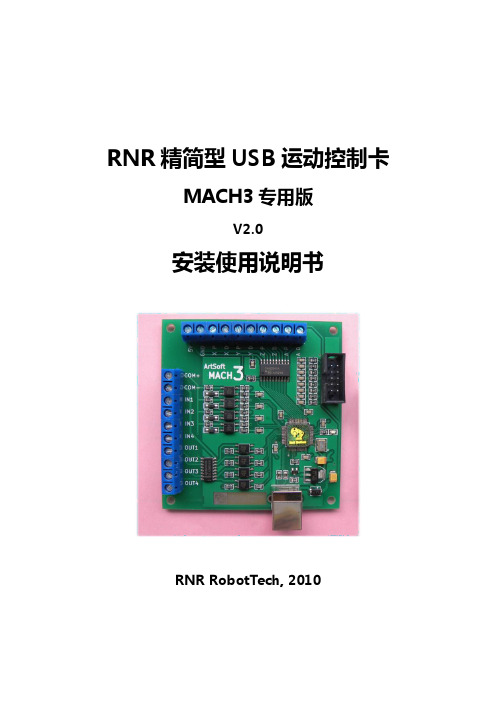
RNR精简型USB运动控制卡MACH3专用版V2.0安装使用说明书RNR RobotTech, 2010目录功能概览 (5)外观及尺寸 (7)接口示意图 (7)安装尺寸图 (8)初次使用 (8)脉冲输出 (11)连接(步进/伺服)电机驱动器 (11)差分方式 (11)单端方式 (12)从属轴设置 (13)其他说明 (14)信号输入 (15)输入信号的接线 (16)急停按钮 (18)限位开关 (19)自动回原点 (21)从属轴的自动回原点 (25)自动对刀 (25)自动刀具清零 (28)自动寻边 (29)寻中心 (31)手轮接口 (32)手轮接线 (33)Mach3的手轮设置 (34)手轮接口作为扩展的信号输入 (36)信号输出 (39)信号输出的接线 (39)主轴电机控制 (40)继电器方式 (41)PWM方式 (42)其他信号输出 (45)警告:由运动控制卡控制的机械设备,具有极强的专业性。
对操作人员的知识及素质有特殊要求。
若设备设计或使用不当,自动设备会具有一定的危险性和破坏性,请确保设计和使用的安全以及遵守相关法规法则,如果不确定,请咨询相关专家而不要冒险。
首次使用者、对本产品或Mach3软件性能不熟悉者,在试验本产品时,请确保机械设备的电源开关在手边并能迅速切断电源。
强烈建议使用者安装急停按钮并保证按钮功能正常。
本公司以"如其所示"的方式提供其产品和服务,对使用本公司产品造成的任何直接/间接人身伤害和财产损失不承担责任。
功能概览RNR精简型USB运动控制卡专用于Mach3软件。
其功能及特点如下:●支持最多4轴联动控制。
其中第4轴可以设为从动轴●输出脉冲100K,采用最小误差插补算法,加工精度高●USB接口,适用任何具有USB接口的上网本,笔记本,台式机以及平板等PC兼容计算机●免驱动设计,能够更好地兼容各种软硬件环境(支持WinXP及WIN7系统)●支持自动回原点(回零)●从动轴在回原点时自动调平●支持自动对刀●支持急停输入●支持限位开关接入●支持主轴控制(PWM方式及继电器方式)●提供4路带光耦隔离数字信号输入●最多提供12路数字信号输入●提供4路带光耦隔离继电器输出●支持手轮接口抗干扰设计,进口工业级元件,可靠性高外观及尺寸接口示意图安装尺寸图初次使用用户第一次使用RNR精简型运动控制卡,要进行一些必要的设置。
INMOTION R1(乐行平衡车)用户手册V1.2
目录1.文档概述 (7)1.1.关于本手册 (7)1.2.驾驶的风险 (7)1.3.驾驶前的准备工作 (7)1.4.相关文档与资料 (8)1.5.相关约定 (8)2.产品概述 (9)2.1.产品尺寸 (9)2.2.产品序列号 (10)2.2.1.产品参数概述 (10)2.3.产品工作原理 (11)2.4.产品主要组成部分 (13)2.5.安装乐行体感车 (14)2.5.1.检查包装箱 (14)2.5.2.组装乐行体感车 (14)2.6.遥控器 (16)2.6.1.遥控器的按钮与显示界面 (17)2.6.2.遥控器的功能与操作 (20)2.7.人机面板与声音提示 (22)2.7.1.人机面板 (22)2.7.2.声音提示 (24)2.8.车体工作模式 (24)2.8.1.车体工作模式简介 (24)2.8.2.各工作模式之间的状态转换图 (26)2.9.车灯 (27)2.10.脚踏传感器 (27)2.11.通讯与外部接口 (28)2.11.1.WIFI接口 (28)2.11.2.GPRS与GPS (29)B充电接口 (30)2.12.手机客户端 (30)3.使用乐行体感车 (31)3.1.骑行乐行体感车 (31)3.1.1.驾驶前的注意事项 (31)3.1.2.启动乐行体感车 (32)3.1.3.上车 (33)3.1.4.前进后退 (34)3.1.5.减速停车 (35)3.1.6.转向 (36)3.1.7.下车 (37)3.1.8.保护您的乐行体感车 (38)3.1.9.关机 (38)3.2.驾驶练习 (38)3.3.新手模式与普通模式 (39)3.4.助力模式 (39)3.5.自动行走模式 (40)3.5.1.遥控模式 (40)3.5.2.动作序列 (40)3.6.自检模式 (41)3.7.安全警报 (42)3.7.1.过速保护 (42)3.7.2.安全停车 (43)3.7.3.振动提示 (44)3.8.环境因素对整车性能的影响 (45)3.8.1.行驶里程 (45)3.8.2.高温骑行 (45)3.8.3.低温骑行 (46)3.8.4.爬坡 (46)3.8.5.下坡 (46)4.电池使用 (47)4.1.安全使用电池 (47)4.2.电池规格 (47)4.3.充电 (48)4.3.1.充电方法 (48)4.3.2.充电指示 (49)4.4.更换电池 (49)4.5.电池运输 (50)5.安全驾驶注意事项 (52)5.1.必须遵守的事项 (52)5.2.严格禁止的事项 (53)5.3.文明安全驾驶注意事项 (54)6.保养与维护 (56)6.1.搬运 (56)6.1.1.使用方向操纵杆搬运 (56)6.1.2.使用提手搬运 (56)6.2.清洁 (57)6.3.存放 (57)6.4.保养 (57)7.常见故障处理 (59)7.1.常见故障列表 (59)7.2.无法开机 (60)7.3.无法进入载人模式 (61)7.4.容易出现抖动 (61)7.5.转向出现问题 (61)7.6.无法关机 (62)7.7.手机客户端无法连接乐行体感车 (62)8.联系方式与法务信息 (63)8.1.问题反馈 (63)8.2.联系我们 (63)8.3.遵守当地法律条款 (63)1.文档概述1.1.关于本手册为了您的驾驶安全,在使用乐行体感车之前请仔细阅读本手册,并请认真观看驾驶指导视频,确保能够按照正确的指导驾驶乐行体感车。
RNR全能型USB运动控制卡V1快速入门手册说明书
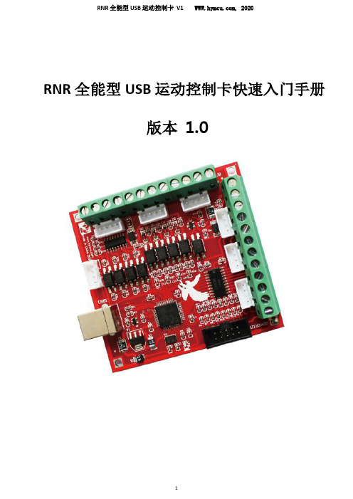
RNR 全能型USB 运动控制卡快速入门手册版本 1.0非常感谢您选购我司飞雕系列MACH3 运动控制卡!本文档将帮助初次接触使用本产品的用户快速完成产品的安装及调试。
准备工作首先,你要准备一台有 USB 接口的电脑。
飞雕系列 MACH3运动控制卡采用 USB 免驱动设计,所以兼容性好。
电脑的操作系统可以是 XP、WIN7、WIN8 系统。
可以是32 位系统,也可以是 64 位系统。
其次,你可能需要准备机床所使用的电机驱动模块的接线端子说明;如果有变频器,还需准备变频器接线端子说明。
42或者57系列电机驱动模块推荐选购我司 TB6600升级版驱动器或者DM542驱动模块。
对于需要连接急停开关、限位开关以及原点开关的用户,你需要准备这些开关和相应的接线端子说明。
急停开关一般采用蘑菇头开关。
限位开关和原点开关分为机械开关和电子开关(光电式、电感式、电磁式等形式)两种,机械开关比较简单,选购也没什么讲究。
选购电子开关时,应当选用 NPN 常开型。
这样比较容易接线。
Mach3 软件安装1、安装 Mach3 软件并运行 Mach3VersionR3.041 安装程序。
Mach3 安装很简单。
只要一直点击下一步(next ),或者是(Yes )即可。
如下图:下载资料中找到Mach3 软件,如图:选择 Mach3 安装位置,一般不需要改动,缺省安装在 C 盘的Mach3 文件夹中。
最后一步需要注意:对于 64 位的电脑,最好不要勾选 Load Mach3 Driver 这一项,因为这会引起系统提示安装错误。
点击“FINSH”。
Mach3 软件就安装完毕了。
2、破解及汉化接下来就是破解和汉化。
打开“mach3 汉化和破解.rar”压缩包。
如图:破解很简单,将压缩包中的文件 Mach1Lic.dat 拷贝到 Mach3 的安装文件夹中,覆盖原有的 Mach1Lic.dat 文件即可。
如果需要安装汉化包,就把“mach3 汉化和破解.rar”压缩包里面的文件全部拷贝至 Mach3 的安装文件夹中,覆盖原有文件。
MotionDrape LED用户手册说明书
User ManualT ABLE OF C ONTENTS1. Before You Begin (3)What Is Included (3)Unpacking Instructions (3)Claims (3)Text Conventions (3)Icons (3)Document Information (3)Product at a Glance (4)Safety Notes (4)2. Introduction (5)Product Overview (5)Product Dimensions (5)3. Setup (6)AC Power (6)Fuse Replacement (6)Mounting (7)Orientation (7)Rigging (7)4. Operation (8)Control Panel Operation (8)Menu Map (8)Configuration (DMX) (8)Starting Address (8)Configuration (Standalone) (9)Sound Mode (9)Automatic Mode (9)Master/Slave Mode (9)DMX Channel Assignments and Values (10)8-CH (10)5. Technical Specifications (11)Returns (12)Contact Us (13)Page 2 of 13 MotionDrape LED User Manual Rev. 91.B EFORE Y OU B EGINWhat Is Included ·MotionDrape LED·MotionDrape Controller·Power Cord·Signal Cable·Carrying Bag·Replacement LEDs·Reusable Zip Ties (Tie Wraps)·Warranty Card·Quick Reference GuideUnpacking Instructions Immediately upon receipt, carefully unpack this product and check the container to make sure you have received all the parts indicated above in good condition.Claims If the box or the contents (this product and any other accessory included) appears damaged from shipping, or shows signs of mishandling, notify the carrier immediately,not Chauvet, upon receipt of the damaged merchandise. Failure to do so in a timelymanner may invalidate your claim with the carrier. In addition, retain the container andall the packing material for inspection.For other issues such as missing components or parts, damage not related to shipping,or concealed damage, file a claim with Chauvet within 7 days of receiving themerchandise.Text ConventionsConvention Meaning1–512 A range of values50/60 A set of values of which only one can be chosen Settings A menu option not to be modifiedMenu > Settings A sequence of menu options to be followed <ENTER> A key to be pressed on the product’s control panel ON A value to be entered or selectedIcons IconMeaningCritical installation, configuration, or operation information. Failure to comply with this information could cause the product not to work, damage it, or cause harm to the operator.Important installation or configuration information. Failure to comply may keep the product from working correctly.Useful information.Document Information The information and specifications contained in this document are subject to change without notice. Chauvet assumes no responsibility or liability for any errors or omissions that may appear in this manual. Chauvet reserves the right to update the existing document or to create a new document to correct any errors or omissions.You can download the latest version of this document from .© Copyright 2016 Chauvet. All rights reserved.Electronically published by Chauvet in the United States of America.MotionDrape LED User Manual Rev. 9 Page 3 of 13Page 4 of 13 MotionDrape LED User Manual Rev. 9Product at aGlanceSafety NotesPlease read the following Safety Notes carefully before working with this product. They include important safety information about its installation, usage, and maintenance.·Always connect this product to a grounded circuit to avoid the risk of electrocution.·Always disconnect this product from the power source before cleaning it or replacingthe fuse.· Avoid direct eye exposure to the light source while the product is on. · Make sure the power cord is not crimped or damaged. · Never disconnect this product from power cord by pulling or tugging on the cord. · Make sure there are no flammable materials close to the unit while operating. · Do not touch this product’s housing when operating because it may be very hot.· Always make sure that the voltage of the outlet to which you are connecting thisproduct is within the range stated on the decal or rear panel of the product.· This product is for indoor use only! (IP20) To prevent risk of fire or shock, do notexpose this product to rain or moisture.· Always install this product in a location with adequate ventilation, at least 20 in(50 cm) from adjacent surfaces.· Be sure that no ventilation slots on the unit’s housing are blocked. · Never connect this product to a dimmer.· Make sure to replace the fuse with another of the same type and rating. · Never carry this product from the power cord or any moving part. · The maximum ambient temperature (Ta) is 104 °F (40 °C). Do not operate thisproduct at higher temperatures.· In the event of a serious operating problem, stop using the unit immediately.· Never try to repair this product. Repairs carried out by unskilled people can lead todamage or malfunction. Please contact the nearest authorized technical assistance center.· To eliminate unnecessary wear and improve its lifespan, during periods of non-usecompletely disconnect the product from power via breaker or by unplugging it.· This product is NFPA-certified fire retardant material.· Keep this User Manual for future consultation. If you sell this product to another user,be sure that they also receive this document.MotionDrape LED User Manual Rev. 9 Page 5 of 132. I NTRODUCTIONProduct OverviewProduct Dimensi o nsLED DisplayFront PanelPage 6 of 13 MotionDrape LED User Manual Rev. 93. S ETUPAC PowerThis product has an auto-ranging power supply and can work with an input voltage range of 100 to 240 VAC, 50/60 Hz.To determine the power requirements for this product (circuit breaker, power outlet, and wiring), use the current value listed on the label affixed to the product’s back panel, or refer to the product’s specifications chart. The listed current rating indicates the product’s average current draw under normal conditions.Always connect this product to a protected circuit (circuit breaker or fuse), making sure that it has an appropriate electrical ground to avoid the risk of electrocution or fire.Never connect this product to a rheostat (variable resistor) or dimmer circuit, even if the rheostat or dimmer channel serves only as a 0 to 100% switch.Fuse ReplacementFollow the instructions below to change the fuse, if necessary.Disconnect this product from the power outlet before replacing the fuse.1. Wedge the tip of a flat head screwdriver into the slot of the fuse holder and pry out ofits housing.2. Remove the blown fuse from its holder and replace with a fuse of the exact sametype and rating.3. Insert the fuse holder back into place, and reconnect power.A spare fuse is not included, but the safety cap does have room for a spare.Always replace a blown fuse with one of the same type and rating.MotionDrape LED User Manual Rev. 9 Page 7 of 13MountingBefore mounting this product, read and follow the Safety Notes .Orientation The MotionDrape LED may be mounted in any position; however, make sure adequateventilation is provided around the product.Rigging Before deciding on a location for this product, always make sure that it will be easy toaccess the unit for maintenance and programming purposes.Make sure that the structure onto which you are mounting this product can support its weight. See the Technical Specifications for weight information.Mount the product securely to a rigging point, whether an elevated platform or a truss. Reusable zip ties (tie wraps) are provided with the MotionDrape LED for quick and easy mounting.This product can be used with the CHAUVET® CH-31 portable truss or any similar portable trussing system.Mounting Diagram4.O PERATIONControl PanelOperation To access the control panel functions, use the four buttons located underneath the display. Please refer to the Product Overview to see the buttons location on the control panel.Button Function<MENU>Press to find an operation mode or to back out of the current menuoption<ENTER> Press to activate a menu option or a selected value<UP> Press to scroll up the list of options or to find a higher value<DOWN> Press to scroll down the list of options or to find a lower valueMenu Map Mode Programming Steps DescriptionVersion V X.X LED-XXX Shows the software version numberAutomatic No Disables automated function Yes Enables automated functionSound No Disables Sound mode Yes Enables Sound modeDmx512No Disables DMX512 modeYesAddress001–512Enables DMX512 mode and sets startingaddressSpeed 1–9 Selects how fast the automated programs runProgram 1–30 NoDisables numbered program running insequence in Automatic or Sound mode YesEnables numbered program running insequence in Automatic or Sound modeConfiguration(DMX) Set this product in DMX mode to control it with a DMX controller.1. Connect this product to a suitable power outlet.2. Turn this product on.3. Connect a DMX cable from the DMX output of the DMX controller to the DMX inputsocket of this product.Starting Address When selecting a starting DMX address, always consider the number of DMX channels the selected DMX mode uses. If you choose a starting address that is too high, youcould restrict the access to some of the product’s channels.The MotionDrape LED uses up to 8 DMX channels in its 8-channel DMX mode, whichdefines the highest configurable address to 505.If you are not familiar with the DMX protocol, download the DMX Primer from.To select the starting address, do the following:1. Press <MENU> repeatedly until Dmx512 shows on the display.2. Press <ENTER>.3. Use <UP> or <DOWN> to select Yes in the menu.4. Press <ENTER>. Address should appear on the screen.5. Use <UP> or <DOWN> to select the starting address.6. Press <ENTER>.Page 8 of 13 MotionDrape LED User Manual Rev. 9Configuration (Standalone) Set this product in one of the standalone modes to control it without a DMX controller.1. Connect this product to a suitable power outlet.2. Turn this product on.Never connect a product that is operating in any standalone mode, whether Automatic or Sound to a DMX string connected to a DMX controller. This is because products in standalone mode may transmit DMX signals that could interfere with the DMX signals from the controller.Sound Mode To enable the Sound mode, do the following:1. Press <MENU> repeatedly until Sound shows on the display.2. Press <ENTER>.3. Use <UP> or <DOWN> to select Yes.4. Press <ENTER>.5. Turn the music on until the product responds to the beat of the music.The product will only respond to low frequencies of the music (bass and drums). Automatic Mode To enable the Automatic Mode, follow the instructions below:1. Press <MENU> repeatedly until Automatic shows on the display.2. Press <ENTER>.3. Use <UP> or <DOWN> to select Yes.4. Press <ENTER>.Master/SlaveMode This mode allows a single unit (the master) to control the actions of one or more units (the slaves) without the need of a DMX controller. The master unit will be set to operate in either Automatic or Sound mode, while the slave units will be set to operate in Slave mode. Once set and connected, the slave units will operate in unison with the master unit. Configure the units as indicated below.Slave units:1. Press <MENU> repeatedly until DMX mode shows on the display.2. Press <ENTER> to accept.3. Use <UP> or <DOWN> to select Yes.4. Press <ENTER>.5. Use <UP> or <DOWN> to select the starting address to: d001.6. Press <ENTER>.7. Connect the DMX input of the first slave unit to the DMX output of the master unit.8. Connect the DMX input of the subsequent slave units to the DMX output of theprevious slave unit.9. Finish setting and connecting all the slave units.Master unit:1. Set the master unit to operate in either Automatic or Sound mode, as previouslyindicated.2. Make the master unit the first unit in the DMX daisy chain.Wait until all the slave units are configured and connected before connecting the master unit to the DMX daisy chain.Never connect a DMX controller to a DMX string configured for Master/Slave operation because it may interfere with the signals from the master unit.Do not connect more than 31 slave units to the master unit.The MotionDrape and MotionFaçade can also be used together in this mode with the same configuration.MotionDrape LED User Manual Rev. 9 Page 9 of 13DMX Channel Assignments and ValuesPage 10 of 13 MotionDrape LED User Manual Rev. 9MotionDrape LED User Manual Rev. 9 Page 11 of 135. T ECHNICAL S PECIFICATIONSDimensions andWeight9.8 ft (118 in)0.6 in (15 mm)6.6 ft (78.7 in) 9.8 lb (4.4 kg) 9.6 in (243 mm)5.3 in (135 mm)2 in (50 mm)1.8 lb (0.8 kg)Note: Dimensions in inches and feet rounded to the nearest decimal digit.PowerPower Supply Type RangeVoltage Selection Switching (internal)100 to 240 V, 50/60 HzAuto-rangingParameter 120 V, 60 Hz230 V, 50 HzConsumption 51 W54 W Operating 0.4 A 0.2 A FuseF 2 A, 250 VF 2 A, 250 VPower input connector IEC IEC Power output connectorEdison IEC Power Cord plugEdison (US)Local plugLight SourceLED17650,000 hoursThermal104 °F (40 °C)ConvectionDMX3-pin XLRSockets8OrderingProduct Name Item Code Item Number MotionDrape LED15090388MOTIONDRAPELEDPage 12 of 13 MotionDrape LED User Manual Rev. 9R ETURNSTo return a product or request support:· In the U.S., contact Chauvet World Headquarters (see Contact Us ). · In the UK or Ireland, contact Chauvet Europe Ltd. (see Contact Us ). · In Mexico, contact Chauvet Mexico (see Contact Us ).· In any other country, DO NOT contact Chauvet. Contact your distributor. See fordistributors outside the U.S., United Kingdom, Ireland, or Mexico.If you live outside the U.S., United Kingdom, Ireland, or Mexico, contact your distributor of record and follow their instructions on how to return Chauvet products to them. Visit our website for contact details.Call the corresponding Chauvet Technical Support office and request a Return Merchandise Authorization (RMA)number before shipping the product. Be prepared to provide the model number, serial number, and a brief description of the cause for the return.You must send the merchandise prepaid, in its original box, and with its original packing and accessories. Chauvet will not issue call tags.Clearly label the package with the RMA number. Chauvet will refuse any product returned without an RMA number.Write the RMA number on a properly affixed label. DO NOT write the RMA number directly on the box.Before sending the product, clearly write the following information on a piece of paper and place it inside the box: · Your name · Your address· Your phone number · RMA number· A brief description of the problemBe sure to pack the product properly. Any shipping damage resulting from inadequate packaging will be your responsibility. FedEx packing or double-boxing is recommended.Chauvet reserves the right to use its own discretion to repair or replace returned product(s).C ONTACT U S USA WORLD HEADQUARTERSGeneral Information – ChauvetAddress: 5200 NW 108th AvenueSunrise, FL 33351Voice: (954) 577-4455Fax: (954) 929-5560Toll free: (800) 762-1084Technical SupportVoice: (954) 577-4455 (Press 4)Fax: (954) 756-8015Email: ************************World Wide WebEUROPEGeneral Information - Chauvet Europe BVBAAddress: Stokstraat 189770 KruishoutemBelgiumVoice: +32 9 388 93 97Technical SupportEmail: *************************World Wide Webwww.chauvetlighting.euGeneral Information - Chauvet Europe Ltd.Address: Unit 1CBrookhill Road Industrial EstatePinxton, Nottingham, UKNG16 6NTVoice: +44 (0)1773 511115Fax: +44 (0)1773 511110Technical SupportEmail: **************************World Wide WebMEXICOGeneral Information - Chauvet MexicoAddress: Av. Santa Ana 30Parque Industrial LermaLerma, Mexico C.P. 52000Voice: +52 (728) 285-5000Technical SupportEmail: ********************.mxWorld Wide Web .mx Outside the U.S., United Kingdom, Ireland, Mexico, or Benelux contact the dealer of record. Follow their instructions to request support or to return a product. Visit our website for contact details.MotionDrape LED User Manual Rev. 9 Page 13 of 13。
MotionCor2使用手册

Shawn Zheng Unviersity of California San Francisco
Version: 1.0.1 Release Date: 09/06/2017 General MotionCor2 is a multi-GPU program that corrects beam-induced sample motion recorded on dose fractionated movie stacks. It implements a robust iterative alignment algorithm that delivers precise measurement and correction of both global and non-uniform local motions at single pixel level, suitable for both single-particle and tomographic images. MotionCor2 is sufficiently fast to keep up with automated data collection. The result is an exceptionally robust strategy that can work on a wide range of data sets, including those very close to focus or with very short integration times. Application significantly improves Thon ring quality and 3D reconstruction resolution. MotionCor2 is a comprehensive program that integrates gain correction, detection and correction of individual and cluster of bad pixels, dose weighting, and supports both MRC and TIFF file format. MotionCor2 is free for academic use and can be downloaded from /em/software/index.html For technical support, please contact, Shawn Zheng: szheng@. For liscensing MotionCor2, please contact, David Agard: agard@ Yifan Chen: YCheng@
GSN系列运动控制器用户手册说明书

GSN系列运动控制器用户手册R1.12019.03版权申明固高科技有限公司 保留所有权力固高科技有限公司(以下简称固高科技)保留在不事先通知的情况下,修改本手册中的产品和产品规格等文件的权力。
固高科技不承担由于使用本手册或本产品不当,所造成直接的、间接的、特殊的、附带的或相应产生的损失或责任。
固高科技具有本产品及其软件的专利权、版权和其它知识产权。
未经授权,不得直接或者间接地复制、制造、加工、使用本产品及其相关部分。
运动中的机器有危险!使用者有责任在机器中设计有效的出错处理和安全保护机制,固高科技没有义务或责任对由此造成的附带的或相应产生的损失负责。
联系我们固高科技(深圳)有限公司地 址:深圳市高新技术产业园南区深港产学研基地西座二楼W211室电 话:************* 26737236 26970824 传 真:*************电子邮件:********************** 网 址:固高科技(香港)有限公司地 址:香港九龍觀塘偉業街108號絲寶國際大廈10樓1008-09室電 話:+(852) 2358-1033 傳 真:+(852) 2719-8399 電子郵件:******************* 網 址:臺灣固高科技股份有限公司地 址:台中室西屯區台中港路三段97號7樓之3 電 話:+886-4-23588245 傳 真:+886-4-23586495電子郵件:***********************文档版本前言感谢选用固高运动控制器为回报客户,我们将以品质一流的运动控制器、完善的售后服务、高效的技术支持,帮助您建立自己的控制系统。
固高产品的更多信息固高科技的网址是。
在我们的网页上可以得到更多关于公司和产品的信息,包括:公司简介、产品介绍、技术支持、产品最新发布等等。
您也可以通过电话(0755-26970817)咨询关于公司和产品的更多信息。
技术支持和售后服务您可以通过以下途径获得我们的技术支持和售后服务:电子邮件:**********************;电话:0755-26970843发函至:深圳市高新技术产业园南区园深港产学研基地西座二楼W211室固高科技(深圳)有限公司邮编:518057用户手册的用途用户通过阅读本手册,能够了解GSN系列运动控制器的基本结构,正确安装运动控制器,连接控制器与电机控制系统,完成运动控制系统的基本调试。
ABB Motion Control产品新手指南说明书

IntroductionAC500 PLCs (PM585 and PM59x) can be used to perform real-time motion control of ABBs EtherCAT enabled servo drives and control distributed EtherCAT I/O devices. This application note details how to use the AC500 programming environment within Automation Builder to detect when the configured EtherCAT devices are operational on the network, ready to be accessed, and how to therefore interlock processing of any EtherCAT related code until these devices are ready.Pre-requisitesYou will need to have the following to work through this application note:· · A MicroFlex e190 or MotiFlex e180 drive with build 5868 or later firmware · A PC or laptop running Automation Builder 2.1.1 or later· An installed (and licensed) copy of the ABB PLCopen motion control library (PS552-MC-E v3.2.0 or later)·One of the following AC500 PLC processors…..PM585, PM590, PM591, PM592 or PM595 (PLC processors should be running firmware version 2.5.1 or later). The PM595 is provided with an integrated EtherCAT coupler (this should be running firmware version 4.2.32.2 or later). All other processors require a CM579-ECAT communication module (which must be running firmware version 2.6.9 or later, but ideally version 4.3.0.2 or later). Contact your local ABB PLC · Ethernet cable to connect the EtherCAT coupler to the drive·A copy of application note AN00205 (AC500 and ABB motion drives - EtherCAT Getting Started Guide) and the Automation Builder PLC project that is included with itTo follow the basic steps to create example code to check the status of the EtherCAT devices only requires a PC or laptop running Automation Builder 2.1.1 or later and an installed copy of the PS552-MC-E motion control libraries. It is assumed the reader has a basic working knowledge of Mint Workbench, Automation Builder, CoDeSys and the AC500 PLC and that the reader has read and understood the contents of application note AN00205, which is also available for download from/motion, and has commissioned an EtherCAT based servo drive (MicroFlex e190 or MotiFlex e180 for example)ready for use with the AC500 PLC.Detecting configured devicesPLC library EtherCAT_AC500_V13.lib is automatically included in the Library Manager for the project when an EtherCAT coupler is included in the PLC’s hardware configuration. This library includes a function block called ECAT_BUS_DIAG which can be used to read the status of, and to return status information for, each slave on the EtherCAT network. This function block can also detect the number of active slave devices connected to the EtherCAT coupler as well as reporting the number of configured devices expected from the Automation Builder hardware tree.By comparing the number of active devices against the number of expected/configured devices the user’s application program can detect when all EtherCAT devices are operational.For this application note we will add our ECAT_BUS_DIAG function block to the project included with application note AN00205, but the same process can be applied to any AC500 motion program using an EtherCAT coupler/network.Add a new network to a program unit called from the lower priority motion related task (in our case we added a network to the very start of the ‘Motion’ program in the PLC project from AN00205). It is logical to place this diagnostic code at the very start of the program as we can use the detection of all of the configured slaves to allow the rest of the code in this program section to execute (or not).Add a new box to this network and enter ECAT_BUS_DIAG as the name of this function block (or use the Input Assistant/F2 to find this function block from the list of standard function blocks)…The table below details the input and output parameters used with this function block…Input Description Data typeEN Enable – this input operates more like an ‘Execute’ input in that the function blockoutputs (e.g. NUM_ACT_SLV) are updated following a rising edge on the EN input.As it takes some time for the EtherCAT network to become operational it is thereforetypical to use a BLINK function block to continually toggle the EN inputTRUE/FALSE and examine the function block outputs on every transition of theDONE outputBOOLSLOT Slot number of the EtherCAT coupler BYTELEN Tells the function block how large the buffer in SLV_STATE is. SLV_STATE is apointer to an array of bytes, where a byte is required for every slave device on theEtherCAT networkWORDSLV_STATE Pointer to an array of bytes. Each byte is used to store information about aconnected EtherCAT slave device. For example, if there were 4 MicroFlex e190drives connected to the EtherCAT coupler than LEN would be set to 4 andSLV_STATE would point to an array of 4 bytes POINTER TO ARRAY OF BYTEOutput Description Data type DONE Indicates the processing state of the block. After completion or abortion ofprocessing (due to an error) the DONE output is set TRUE for one program cycle.This output should always be considered in conjunction with the ERR outputBOOLERR Indicates whether an error occurred during processing of the block BOOL ERNO Provides an error identifier if ERR is set TRUE. See the Automation Builder Helpsystem for further information about possible ERNO codesWORDNUM_ACT_SLV Indicates the number of EtherCAT slaves active on the EtherCAT network (i.e.Operational and exchanging cyclic data with the AC500’s EtherCAT coupler)DWORDNUM_CONF_SLV Indicates the number of EtherCAT slaves configured via the Automation Builderdevices tree (maximum number of slave devices is 256)DWORDEach byte in the array of bytes pointed to by SLV_STATE indicates the actual state of the EtherCAT slave controller on a drive. Possible values for the byte are:1Init State2Pre-Operational State3Request Bootstrap State4Safe-Operational State8Operational StateIf a byte indicates a value other than 8 then it is certain that the slave device is not operational. However, just because the byte may indicate a value of 8 (Operational) it doesn’t mean the slave device really is operational….the network could have an issue and the PLC may be unable to read the current status of the slave.We therefore aren’t typically too worried about examining the content of these bytes and instead just concentrate on the active nodes diagnostic.For our example we only have a single drive connected to our EtherCAT coupler so our completed network and our associated variable declarations look like this…We can then create some logic to set and reset an “EtherCAT ready” Boolean variable that we can use as an interlock in our motion program (e.g. we could exit the motion program before processing any of our motion function blocks if we’ve detected the network is not yet fully operational). The screenshot below illustrates some typical logic to fulfill this sort of functionality…Contact UsFor more information please contact yourlocal ABB representative or one of the following:/motion /drives/drivespartners /PLCEtherCAT® is a registered trademark and patented technology, licenced by Beckhoff Automation GmbH, Germany© Copyright 2016 ABB. All rights reserved.Specifications subject to change without notice.。
运动控制操作说明
成一个位置设定对象, 在对象列表中选中该对象, 系统会在属性框中显示该对象的属性 (如下图右所示) 。
第 3 页 共 9 页
图3 图4 作用:打标时软件是按照对象列表中的顺序来执行,在执行到运动对象时,会执行您设 置的运动,如果需要调节对象在文档中的位置,可在文档对象列表中用鼠标进行拖动。 2.2 圆周旋转专用打标应用 本功能集成了标尺绘图、 数据处理及打标控制等多种工具, 目的是给使用者提供一个简 单快捷的方式快速处理大多数圆周标记应用。 2.2.1 圆周标记应用常见应用: A) 、非连续图形,能被拆解且不影响效果,比如:普通文字、PLT(LOGO)图形等。
第 4 页 共 9 页
图7 如上图所述, 这种情况下为了提高效率及增强填充线底纹效果, 对于有填充线的图 形需要进行填充线专用标记方式(软件只标记竖向填充线,忽略其它填充线)。 如果 “填充线每次标记个数” 设置为3,则每次只标记3根填充线,然后旋转到 随后三根填充线的中间线位置再进行标记),此标记方式可通过设置合理的填充线标记 个数来调节打标效果,对于没有填充线的轮廓图形,则采用B方式处理,我们称之为等 角度综合标记方式。 2.2.2 圆周旋转打标参数设置 菜单设置旋转打标设置,系统会弹出如下对话框:
第 5 页 共 9 页
,将图案打散成线条。
按钮,系统会根据您所设置的直径对数据进行重组,生成一
第三步:检查打标对象组合是否合理,如果不合理需要手动处理。 第四步:如果需要填充,再进行整体填充,切记不要先填充再打散重组。 2.2.4 旋转打标 做好前 3 步的准备工作后,就可以进行旋转打标了。在工具栏点击旋转打标 按钮,系统会弹出如下对话框:
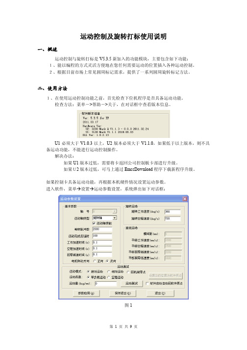
运动控制及旋转打标使用说明
一、概述
运动控制与旋转打标是 V5.3.5 新加入的功能模块,主要包含如下功能: 1、能以编程的方式灵活方便地在您任何需要运动的位置插入各种运动控制。 2、根据目前市场上常见圆周标记需求,提供了一系列圆周旋转标记方法。
inmotion v3 使用手册说明书
使用手册1.IntroductionINMOTION V3 is a self-balancing unicycle type SCV (Sensor Controlled Vehicle). It is stylish, fun and practical, integrated with a unique hidden draw-bar, auto-switch lights, a touch screen, a slide-to-open charging port and built-in high quality Bluetooth speakers. INMOTION V3 is easy to learn, safe to ride, practical to commute.提手按钮提手握开关灯装饰板拉杆组件脚踝护垫动力电机充电口触摸开小腿护脚踏橡胶轮停车脚垫蓝牙音箱前/后灯提手按钮 Draw-bar Button提手握 Handlebar拉杆组件 Draw-bar Assembly复位开关 Reset Button充电口 Charging Port前/后灯 Lights装饰板 decorating plate脚踝护垫 Ankle Pad动力电机 Motor触摸开关 Touch Screen小腿护垫 Calf Pad蓝牙音箱 Bluetooth Speaker脚踏板 Footboard停车脚垫 Stop-stand Rubber橡胶轮胎 Tire2.PackagingINMOTION V3 package includes the following parts when leaves the factory. Please check carefully before using the product, any missing or visible damaged parts should be reported to your dealer immediately.manual1 INMOTOIN2 User’sV33 Charger Adaptor4 Warranty card, Product Certificate3.Safety AlertINMOTION V3 balances front and back, and stands by itself with its two tires. INMOTION V3 is a reliable product and it has gone through many rigid tests. Due to its new idea of driving, we still ask you to follow all the instructions in this manual and be careful with all the warnings and cautions.You may risk falling off/over, crashing, losing control of the vehicle and so on if you do not follow the instructions to ride INMOTION V3. Again please carefully and thoroughly read this manual and watch related safety videos.3.1Warningz Wear a helmet, elbow and knee protection when riding the INMOTION V3.z Do not ride on steep slopes that are over 20 degrees.z Do not accelerate and decelerate hardly or abruptly on the slopes.z Pay attention to obstacles and be careful of skid when riding the INMOTION V3.z Do not ride on grass.z Do not ride on pebble roads or any other unsmooth surfaces.z Do not drive into water that is over 170 mm.3.2Prohibitionz Do not go up and down stairs or spring off the ground with the INMOTION V3.z Do not ride the INMOTION V3 on motor roads. Some local authorities forbid the use of Sensor Controlled Vehicles on public roads and sidewalks. Please consult localauthorities to become familiar with applicable laws and regulations before riding.z Do not dip the INMOTION V3 into water.z Do not drive the INMOTION V3 over 20 km/h (12 mph).z Do not accelerate hardly when the INMOTION V3 is not totally balanced.z Do not sit on the draw-bar or any other parts when riding.4.General Information4.1DimensionsFigure 2.1 INMOTION V3 Dimensions4.2Display PanelFigure 2.2 Display PanelLightPowerSlide Direction5.How to Use5.1Power OnTouch the Power icon and gently slide towards the arrow direction (Figure 3.1).5.2Hibernation and Shutdownz Touch the Power icon and slide towards the arrow direction to hibernate the system. In between you may also hear a sound prompt. In hibernation mode, if the system is leftunoperated for 2 hours, the system will automatically shut down.z You can directly shut down the system in hibernation mode by pressing the end of the scrolling bar for about 5 seconds.z If the remain power is less than 10%, the hibernation action will also directly shut the system down.Tip: if the touch panel is not responding, or the system cannot be shut down in an emergent situation, please lay flat the INMOTINO V3 for 2 times in 3 seconds and you will hear “Please be careful”, then you can possibly shut down the system.5.3LightPower on the system and slide your finger from right end to left end (towards the opposite arrow direction), the lights on both sides will be illuminated in white. Roll the INMOTION V3 in a direction, the front light will illuminate in white with full brightness and the back light will turn into red. The lights will automatically change in white and red according to the riding direction of INMOTION V3.5.4Bluetooth SpeakerThe built-in Bluetooth module is automatically activated when the INMOTION V3 ispowered on.Turn on Bluetooth on your cellphone, search and pair the Bluetooth signal of the INMOTION V3 (Figure 3.4). If the signals are successfully paired, you may play music through the INMOTION V3’s Hi-Fi loud speakers.5.5Assist ModePress down the draw-bar button, pull up the handle till the highest and then release the button. Now you can trolley the INMOTION V3 like a suitcase.Figure 3.55.6Power IndicatorThere are two battery indicators along the two sides of the touch panel. Each has 6 bars, if the power is over 90%, all 6 bars are illuminated, and if the power is less than 20%, only 1 barwill be illuminated. 5.7 Charge INMOTION V3Slide to open the charging port to charge. If the INMOTION V3 is charging, the charging indicator on the Charger Adapter illuminates in red and the Battery Indicator Bars are rolling up and down. If the INMOTION V3 is fully charged, the charging indicator is in blue.Figure 3.6 5.8 Voice PromptThe system’s default prompt language is Chinese or English, you can change to other languages IF available through INMOTION APP. Here below are some basic voice prompts:1 Welcome2 Hibernation3 Lock4 Unlock5 Low Battery6 Charging7 Power full8 Overload, please get off9 Light is on 10 Light is off 11 Please slow Down 12 Power off13 Please Repair14 Please don’t move the device 15 Data Bluetooth connected 16 Data Bluetooth disconnected 17Music Bluetooth connected18Music Bluetooth disconnected19 Please be careful 205.9ResetWhen unknown errors or abnormal situations occurred, you can press the Reset button to turn off the INMOTION V3 completely.The Reset button can be seen after sliding the charging port cover to the right and it is on the left side of the charging port.5.10Water and Dust ProofV3 is rated IP55 for water and dust proof. It can maximally pass through 170 mm deep water.5.11Over Speed ProtectionWhen the speed is over 18 km/h (11 mph), the footboard will lean back at about 3~4°. The rider can continuously drive at the current speed. If the speed over 20 km/h (12 mph), the footboard will lean back to protect the rider’s safety.5.12Side-tipping ProtectionWhen the INMOTION V3 is side tipping over 45°, it will regard it as an abnormal situation and will exit balance mode, while there will be a voice prompt “Please be careful”. Place the INMOTION V3 to stand and then it will automatically balances itself again.5.13Over Discharge ProtectionThe system of INMOTION V3 will automatically cut off the entire power when the battery islow under hibernation or power off mode. Low battery will make INMOTION V3 to lean back to warn the rider, there will also be a voice prompt.The system will protect the battery from over discharging when it is powered off. You may wake the V3 by charging the battery, if the INMOTION V3 is still not awaken please contact your dealer for a diagnosis.5.14Smart Phone ApplicationThe Application for INMOTION V3 works via Bluetooth 3.0 to connect the vehicle, it is suitable for Android 4.3 and above, iOS 7.0 and above (iPhone 4s and later models only). Some functions are listed as below:1 My SCV2 Parameter settings3 My Profile4 My Route5 Firmware Update6 Sound Customization7 Social 8 Diagnosis9 Log 10 ServiceFor more information about the INMOTION APP, please visit 6.Maintenance6.1DepositInappropriate store the INMOTION V3 may cause damage to the battery, please pay special attention to below warnings.z The best storage temperature is about 20 ℃ (68 ℉). Too high or too low temperature should be avoided.z Please avoid strong humidity.z Please charge the INMOTION V3 at least one time a month event it is powered off.6.2InflationPlease inflate tires in time to make sure the pressure of the two tires are the same. The default tire pressure is 3.5 Bar.6.3Change TireIf you need to change the tires, please contact an authorized INMOTION service center or your dealer.6.4Adjust FootboardPlease use a M8 screwdriver to adjust the tightness of the footboards if needed.6.5CleaningPlease gently clean the INMOTION V3 cases with a piece of soft cloth with clear water or soap water.6.6WarrantyINMOTION provides below warranties for non-human made malfunctions and damages for INMOTION V3.One year warranty for the entire vehicle (Battery and Tires excluded)6 months for the Battery3 months for both inner/outer tiresAppendix: parameters No. Item Value Note1Max. Speed18 km/h (11 mph)This speed is tested with a 75 kg (165 lbs) payload.2Distance per charge20~25km (12.5~15.5 miles)The distance per charge is obtained under the following test conditions: room temperature, 75 kg (165 lbs) payload and smooth terrain.3 Climbing Angle 18°4 Recommended best operating temperature -10~40℃(14~104°F)5 Max load 120 kg (265 lbs)6 Charge time 1.5 H 7Power requirementsAC 100-230 V 50~60 Hz8 Dimensions 420 x 515 x 178 mm 9 Tire size 14 inches 10Weight13.5 kg (30 lbs)7. Operation and Learning 7.1PreparationWhen you attempt the first use, please wear comfortable clothes and shoes. We strongly suggest the beginners to wear a helmet and other protections to avoid serious injuries.Please take the INMOTION V3 onto smooth roads in an open space and then start to learn. 7.2 8 Stepsz Hold the INMOTION V3 still and power it on.z Unfold the footboards and stand one foot on one footboard with force. z Press your calf against the calf pad and push inward to another leg.z Now practice sliding the vehicle forward with only one foot on, while another footpushing off the ground.z Make sure that the INMOTION V3 would always be right in the middle of your legs and not go other directions.z Keep your body straight up and get relaxed, look forward and naturally get on another foot. When you lift another foot off the ground, your body weight is slightly shifting to the foot standing on the footboard.z It is better that someone can hold your arms to help you get balanced or you can learn to get on the vehicle by pushing your hands against a wall.z Try to find your balance standing both feet on the INMOTION V3 and relax your calves. z Someone can hold your arms and lead you drive forward and backward.z When you get used to the feeling, now try to learn forward to go forward and lean backward to go backward.z Learn how to turn is always hard, make sure you are able to drive forward and backward very smoothly.z When you want to turn, twist your upper body towards the direction and push the INMOTION V3 inward. Your upper body will naturally move to the opposite direction to keep you balanced.z Since INMOTION V3 actually has two tires, it is easier to turn with one tire touching the ground and another off the ground.7.3Cautionsz Beginners who are under 18 or over 45 need someone as an assistant to help learn.z Please make sure the battery is fully charged before use and the tires are properly inflated. z Please do not drive fast before you are familiar with riding it. Please accelerate slowly.For more information, please visit our official website .INMOTION Customer Care Center: 4000-1000-12+86 (0)755-8209-17688.Warranty CardCustomer purchase information registrationCustomer name Serial Number Purchasing dateTelephoneE-mailCustomer’s addressDealer’s Name Dealer’s telephoneDealer’s address9. Maintenance recordDate Description of malfunctionSolution Authorized SignatureRemarkLimitation for warrantyThe obligations and responsibilities of warranty of INMOTION for the products and accessories, are restricted to free maintenance of reparation and replacement of defective parts within warranty periods. INMOTION assumes no responsibility (also does not authorize any third party to assume the responsibility) for service beyond this scope. Liability exemption is including but not limited to labor force losses, property losses, and other losses caused during the maintenance period. This limited warranty term is the only applicable guarantee clause for the maintenance towards the INMOTION SCV and its spare parts. INMOTION does not endorse any other guarantee or implied guarantee beyond this limited warranty term. INMOTION assumes no responsibility for other commitments that you make with the third party. This regulation comes into force from the day of its promulgation. The PICC (People’s Insurance Company of China) insures the INMOTION SCV series products. INMOTION Technologies Co., Ltd. Reserves the right of final explanation, reproduction, and revision for the contents in this warranty card.FCC Caution: Any changes or modifications not expressly approved by the party responsible for compliance could void the user's authority to operate this equipment.This device complies with Part 15 of the FCC Rules. Operation is subject to the following two conditions: (1) This device may not cause harmful interference, and (2) this device must accept any interference received, including interference that may cause undesired operation.NOTE: This equipment has been tested and found to comply with the limits for aClass B digital device, pursuant to Part 15 of the FCC Rules.These limits are designed to provide reasonable protection against harmful interference in aresidential installation. This equipment generates, uses and can radiate radiofrequency energy and, if not installed and used in accordance with theinstructions, may cause harmful interference to radio communications.However, there is no guarantee that interference will not occur in a particular installation.If this equipment does cause harmful interference to radio or television reception,which can be determined by turning the equipment off and on, the user is encouraged totry to correct the interference by one or more of the followingmeasures:-- Reorient or relocate the receiving antenna.-- Increase the separation between the equipment and receiver.-- Connect the equipment into an outlet on a circuit different from that to which thereceiver is connected.-- Consult the dealer or an experienced radio/TV technician for help.。
MotionCam 无线运动检测器用户手册说明书
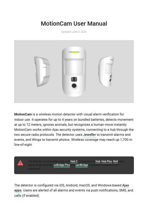
MotionCam User ManualUpdated June 3, 2020MotionCam is a wireless motion detector with visual alarm veri cation forindoor use. It operates for up to 4 years on bundled batteries, detects movement at up to 12 meters, ignores animals, but recognizes a human move instantly.MotionCam works within Ajax security systems, connecting to a hub through the two secure radio protocols. The detector uses to transmit alarms and events, and Wings to transmit photos. Wireless coverage may reach up 1,700 m line-of-sight.The detector is compatible only with . Connection to , , radio signal range extender, and integration modules is not supported!The detector is con gured via iOS, Android, macOS, and Windows-based . Users are alerted of all alarms and events via push noti cations, SMS, and calls (if enabled).Jeweller Hub 2Hub Hub Plus ReX ocBridge Plus uartBridge Ajax appsThe Ajax security system can be used for self-reliant monitoring, or can beconnected to a security company’s central monitoring station.Functional ElementsOperating PrincipleThe infrared sensor of MotionCam detects intrusion into the secured premises by identifying moving objects with a temperature close to that of the human body. The function makes the detector effectiveBuy MotionCam motion detector featuring visual alarm veri cation1. LED indicator2. Motion detector lens3. Infrared illumination for shooting in the dark4. Camera5. SmartBracket mounting panel (the perforated part is necessary for tamper activation in case of an attempt to detach the detector from the surface)6. Tamper button7. Power button8. QR codetemperature compensationinside premises with temperature ranging from 0 to +40°C. If placed and adjusted properly, MotionCam ignores pets.When movement is detected, the armed detector instantly transmits an alarm signal to the hub. The hub activates the connected sirens and noti es the user and the security company. MotionCam uses radio protocol to transmit alarms and events to the hub.The built-in MotionCam camera can take from 1 to 5 shots with the resolution of 320×240 and up to 3 shots with the resolution of 640×480 pixels. A series of photos is displayed in the app as an animation, so the user is able to evaluate the unfolding of the event over time. Photos are available both in Ajax apps and on the Central Monitoring Station software of the security company. MotionCamuses Wings radio protocol to transmit photos to the hub.The detector features infrared illumination for shooting in the dark, which is activated only when triggering.Photo delivery time in the Ajax apps depends on the resolution and the speed of your internet connection. The table shows the delivery time for one photo at a signal strength of 2-3 divisions between the hub and MotionCam and the hub connected via Ethernet.Photo resolutionDelivery time 160 × 120up to 7 sJeweller320 × 240 (default setting)up to 9 s 640 × 480up to 20 sAt the same time, an alarm is transmitted within 0.15 s.Pairing the Detector with the hub Before you start pairing the detector:Please note that only a user with admin permissions can add devices to the hub.To connect the detector:For detection and pairing to occur, the device must be within a hub’s wireless coverage (at the same facility).1. Turn on the hub and check the Internet connection (via Ethernet cable and/or GSM network).2. Install the on your smartphone. Create an account, add the hub to the app, and create at least one room.Ajax app 3. Check the status of the hub in the app to make sure it is disarmed and is not updating.1. In the Ajax mobile app, tap Add Device .2. Name the device, scan or enter manually the QR code (placed on the back of the detector body or its packaging), select the room for placement.3. Click Add . The countdown will start.4. Turn on the device by holding its power button for 3 seconds. Please note that the hub connection request is only sent for a short time while switching on the device.MotionCam turns off automatically within 6 seconds after activation if it fails to connect to the hub. There is no need to turn off the device to retry.If the device has already been paired with another hub, turn MotionCam off, and then follow the standard pairing procedure.After pairing, the detector will appear on the app’s hub device list. The frequency of the device status updates depends on the polling interval indicated in the hub’s settings (36 seconds by default).StatusesYou can view MotionCam states in the detector menu.1. Ajax app Devices MotionCamParameterValueTemperatureDetector temperature. Measured on the processor and changes graduallyJeweller Signal StrengthThe strength of the signal for transmitting alarms and events between the hub and the detectorBattery chargeThe detector battery charge, displayed in the increments of 25%LidThe status of the detector’s tamper device that responds to the detachment and removal attempts.Delay when entering, sEntry delay (alarm activation delay) is the time you have to disarm the security system after entering the roomDelay when leaving, sDelay time when exiting. Delay when exiting (alarm activation delay) is the time you have to exit the room after arming the security systemConnectionConnection status between the hub and the detectorWings Signal StrengthThe strength of the signal for transmittingWhat is delay when enteringWhat is delay when leavingphotos from the detector to the hubCamera Connection status between the hub and the detector’s cameraSensitivity Sensitivity level of the motion detectorAlways active If active, the detector is always in the armed modeFirmware Detector rmware version ID Device IDSettingsYou can adjust the device parameters in the settings section:1. Ajax app Devices MotionCam SettingsSettingsValueFirst eld Detector name (editable)RoomThe virtual room to which the device can be assignedSensitivityMotionCam detector has three sensitivity levels:Always activeIn Always Active mode, the detector always registers motion. Regardless of whether thesystem is armed, the detector will alert you about any motion. Activate this mode if the detector is installed in a room requires 24/7monitoring.Image resolutionMotionCam takes photos with the following resolutions:High — for rooms with a minimum amount of obstacles; in this mode, the movement is detected as quickly as possible.Medium — for rooms with potential obstacles:open windows, air conditioners, heaters, etc.Low — for rooms with a high amount of obstacles; in this mode, the detector ignores animals weighing under 20 kg and up to 50 cm tall160 × 120320 × 240The higher the resolution, the more detailed the image is, but it takes longer to transmit the photos to the hubSend photo in case of alarmWhen triggered, the detector takes from 1 to 5photos.If the No photo option is selected, the detector does not activate the camera when triggered.Alarms with photo con rmationMotionCam can take photos every time alarm israised or only while rst 1 to 10 activations. The limit is reset once the security system is disarmedDelay when entering, sSelecting delay time when entering. Delay when entering (alarm activation delay) is the time youhave to disarm the security system after entering the roomDelay when leaving, sSelecting the delay time when exiting. Delay when exiting (alarm activation delay) is the time you have to exit the room after arming thesecurity systemDelays in Night ModeActivation of the delay when Night mode is enabledArm in Night ModeIf active, the detector switches to the armed mode when night mode is enabledAlert with a siren if motion is detectedIf active, and are activated when motion is detected.Jeweller Signal Strength TestSwitches the detector to the Jeweller signal strength test mode. The test checks the signal640 × 480What is delay when enteringWhat is delay when leavingWhat is night modeWhat is night modeHomeSiren StreetSirenstrength between the hub and the detector, and helps to determine the optimum installation placeWings Signal Strength TestSwitches the detector to the Wings signalstrength test mode. The test checks the signal strength between the hub and the detector, and helps to determine the optimum installation placeDetection Zone TestSwitches the detector to the detection zone test mode. The test checks how the detector responds to motion and determines theoptimum installation placeAttenuation TestSwitches the detector into the signal attenuation test modeUser Manual Opens the detector User ManualUnpair deviceUnpairs the detector, disconnects it from the hub, and deletes its settingsPhoto Veri cation of Alarms in Ajax appsIf the Send photo in case of alarm option is enabled in the MotionCam settings,detector alarms will be accompanied by photos or animations in Ajax apps.To view photos, click on the alert noti cation in the events feed.What is Signal Strength TestWhat is Detection Zone TestWhat is Attenuation TestTo save the photo, click on the appropriate button.evaluate the unfolding of the event over time.Each frame of a series of photos can be saved individually. The entire series can be saved at once or MP4 video.IndicationThe MotionCam LED indicator may turn red or green, depending on the status ofthe device.Indication when pressing the power buttonEventIndicationTurning onLights up green while the device is turning onFeatures of alarm photo veri cation by MotionCam detectorsTurning off Lights up red, then ashes three timesActive detector indicationEventIndicationNoteConnecting the detector to the hubLights up green for a few secondsHardware errorFlashes redThe detector needs to berepaired, please Alarm or tamper activationLights up green for about 1secondBattery replacement neededSlowly lights up/goes outgreen when an alarm is raisedFor battery replacement procedure, see manualFunctionality TestingAjax security systems can run tests to verify the functionality of connected devices.The tests do not start immediately but within 36 s under default settings. The test start delay depends on the detector polling period settings (see Jeweller settings section in hub settings).The tests are available in the detector settings menu (Ajax application Devices MotionCam Settings ) :If any interference is detected or the signal strength is too low to transmit images, the user will receive a push noti cation “High interference at Wings frequencies”.contactSupport ServiceBatteryReplacement Jeweller Signal Strength Test Wings Signal Strength Test Detection Zone Test Attenuation TestDetector PlacementThe location of the detector directly affects the e ciency of the security system. The location of the MotionCam detector is determined by its distance from the hub and presence of any obstacles between the devices hindering the radio signal transmission: walls, intermediate oors, or large-size objects located in the room.Choosing a location to install, consider the orientation of the lens, the viewing angles of the detector and the camera, and the presence of obstacles that obstruct the view. It is recommended to aim the detector lens perpendicular to the intended path of intrusion into the room. Make sure that furniture, house plants, vases, decorative or glass elements do not obstruct the eld of view of the detector.Horizontal and vertical viewing angles of the detectorThe detector does not detect movement behind the glass. Therefore, do not install it in locations where glass objects can obstruct its eld of view. For example, in places where an open window can obstruct the eld of view of the detector.Remember to check the signal strength at the installation site. If the signal strength islow (a single bar), we do not guarantee a stable operation of the security system!If the detector has low signal strength, take whatever action is possible to improve the quality of communication! At a minimum, relocate the device:repositioning by even 20 cm can signi cantly improve the reception quality. Detector InstallationBefore installing the detector, make sure that you have chosen an appropriate location asindicated in this manual.The recommended height of the installation is 2.4 m. If the detector is not installed at the recommended height, this will reduce the area of the motion detection zone and disrupt the operation of the pet immunity function.Use the SmartBracket mounting panel to mount the MotionCam detector on a vertical surface or in a corner. SmartBracket has special recesses for xing it with the bundled screws.To install the detector:1. Attach the SmartBracket panel to the surface with bundled screws, using atleast two xing points. To make sure that tamper reacts to an attempt todismantle the device, x the perforated corner of the SmartBracket:Double-sided adhesive tape should be used only for the temporary installation ofthe detector. The tape dries up over time, which may result in the falling of thedetector and triggering of the security system. Moreover, the device may fail if hit.2. Attach the detector to the mounting panel. As soon the detector is xed inSmartBracket, its LED blinks once to signal that the tamper on the detectorhas been triggered.If the detector’s LED doesn’t light up after the device is attached to theSmartBracket, check the tamper status in the Ajax app and then check if it ts tightly onto the attachment panel.Do not install the detector:MaintenanceCheck the operability of the detector on a regular basis. Clean the detector body from dust, cobwebs, and other contaminants as they emerge. Use a soft dryoutdoors;facing the window to avoid exposing the detector lens to direct sunlight;opposite any objects with the rapidly change temperature (e.g. opposite electric or gas heaters);opposite any moving objects with the temperature close to that of the human body (opposite swaying curtains above the heater);in places with fast air circulation (next to fans, open windows or doors);near metal objects and mirrors that cause the attenuation or interfere with radio signals;inside rooms with temperature and humidity beyond the permissible limits;closer than 1 meter to a hub.cloth suitable for equipment care.Do not use substances that contain alcohol, acetone, gasoline or other active solvents to clean the detector. Wipe the lens very carefully — any scratches on the plastic may impair the detector sensitivity.The pre-installed battery ensures up to 4 years of autonomous operation. If the detector battery is nearly depleted, the security system will send a noti cation,and the LED will smoothly light up and go out when the detector detects anymotion or if the tamper is activated.Technical Speci cationsSensitive element PIR sensor Motion detection rangeUp to 12 m Motion detector viewing angle (H/V)88.5°/80°Image resolutionUp to 640 × 480 pixels Number of photos taken when alarm is raised Up to 5 photos/single alarm Infrared illumination for shooting in the darkYesPet immunityWeight up to 20 kg, height up to 50 cmTamper protection YesFrequency band868.0 – 868.6 MHz or 868.7 – 869.2 MHz,depending on the sales regionCMS compatibilityMotion alarms are transmitted to CMSs thatsupport SIA and Contact ID protocols.Visual alarm veri cations are transmitted to the Manitou, ABsistemDC(NG) and SBN CMS, and Ajax PRO Desktop app Maximum RF output powerUp to 20 mWWhat is the MotionCam battery life and what does affect it Battery ReplacementWhy motion detectors react to animals and how to avoid it >Radio signal modulation GFSK Radio signal range (line-of-sight)Up to 1,700 mPower supply 2 CR123A batteries, 3 V Battery lifeUp to 4 yearsOperating temperature rangeFrom 0°C to +40°C (manufacture date up to June 1, 2020)From -10°C to +40°C (manufacture date from June 1, 2020)Operating humidity Up to 75%Overall dimensions 135 × 70 × 60 mm Weight167 gComplete SetWarrantyWarranty for the AJAX SYSTEMS MANUFACTURING Limited Liability Company products is valid for 2 years after the purchase and does not extend to the bundled battery.If the device does not function correctly, please contact the Support Service rst. In half of the cases, technical issues can be solved remotely!How to nd the manufacture date of a detector or device1. MotionCam2. SmartBracket mounting panel3. 2 CR123A batteries (pre-installed)4. Installation kit5. Quick Start GuideWarranty Obligations。
VTEM Motion Terminal手动说明书
Festo — VTEM — 2021-05f
3
3.7.5 保存示教数据 . . . . . . . . . . . . . . . . . . . . . . . . . 72 3.7.6 参数更改后示教数据的有效性 . . . . . . . . . . . . . . . . . . 72 3.8 诊断方式. . . . . . . . . . . . . . . . . . . . . . . . . . . . . . . 72 3.8.1 LED 显示元件 . . . . . . . . . . . . . . . . . . . . . . . . . 73 3.8.2 诊断接口 . . . . . . . . . . . . . . . . . . . . . . . . . . . 76 3.8.3 传输模式的诊断通道 . . . . . . . . . . . . . . . . . . . . . . . . . . . . . . . . . . . . . . . . . . . . . . . . . 83 4.1 设置系统、应用和整定参数 . . . . . . . . . . . . . . . . . . . . . . . 83 4.1.1 前提条件. . . . . . . . . . . . . . . . . . . . . . . . . . . 83 4.1.2 流程. . . . . . . . . . . . . . . . . . . . . . . . . . . . . 83 4.2 读取系统、应用和整定参数 . . . . . . . . . . . . . . . . . . . . . . . 84 4.2.1 前提条件. . . . . . . . . . . . . . . . . . . . . . . . . . . 84 4.2.2 流程. . . . . . . . . . . . . . . . . . . . . . . . . . . . . 85 4.3 设置传感器参数 . . . . . . . . . . . . . . . . . . . . . . . . . . . . 86 4.3.1 前提条件. . . . . . . . . . . . . . . . . . . . . . . . . . . 86 4.3.2 过程. . . . . . . . . . . . . . . . . . . . . . . . . . . . . 86 4.4 设置用于描述自定义驱动器的参数 . . . . . . . . . . . . . . . . . . . . 88 4.4.1 前提条件. . . . . . . . . . . . . . . . . . . . . . . . . . . 88 4.4.2 过程. . . . . . . . . . . . . . . . . . . . . . . . . . . . . 88 4.5 永久保存参数设置 . . . . . . . . . . . . . . . . . . . . . . . . . . . 89 4.6 切换激活参数组 . . . . . . . . . . . . . . . . . . . . . . . . . . . . 89 4.6.1 前提条件. . . . . . . . . . . . . . . . . . . . . . . . . . . 89 4.6.2 流程. . . . . . . . . . . . . . . . . . . . . . . . . . . . . 89 4.6.3 示例. . . . . . . . . . . . . . . . . . . . . . . . . . . . . 90 5 技术性附录. . . . . . . . . . . . . . . . . . . . . . . . . . . . . . . . . 91 5.1 技术参数. . . . . . . . . . . . . . . . . . . . . . . . . . . . . . . 91 5.1.1 概述. . . . . . . . . . . . . . . . . . . . . . . . . . . . . 91 5.1.2 电源. . . . . . . . . . . . . . . . . . . . . . . . . . . . . 93 5.1.3 认证. . . . . . . . . . . . . . . . . . . . . . . . . . . . . 93 5.1.4 输入模块. . . . . . . . . . . . . . . . . . . . . . . . . . . 93 6 支持的外设. . . . . . . . . . . . . . . . . . . . . . . . . . . . . . . . . 94 6.1 支持的 CPX 总线节点 . . . . . . . . . . . . . . . . . . . . . . . . . . 94 6.2 所支持的驱动器列表 . . . . . . . . . . . . . . . . . . . . . . . . . . 95 7 许可证. . . . . . . . . . . . . . . . . . . . . . . . . . . . . . . . . . . 95
MotionFoot MX 用户指南说明书
MotionFoot® MXUser GuideMotionFoot® MXUser GuideIntroductionThank you for purchasing the MotionFoot® MX. No other foot has the anatomical range of motion of the MotionFoot® MX. T his results in smooth, gliding gait on flat terrain, and unparalleled stability on descending slopes.Please take a moment to study this manual as it descri bes the advantages, functions, adjustments, and warnings regarding the MotionFoot® MX,for you to maximize safety, comfort, and reliability. Features of the MotionFoot® MX• A full anatomical 50 degrees range of motion• Wearer adjustable plantar flexion* and dorsi flexion** resistance• Moving fulcrum keel design for dynamic foot response• Ankle Lock for ease of donning shoes/driving, etc.* Plantar flexion - the ankle motion as the foot goes to the floor when the heel strikes the ground** Dorsi flexion - the motion as the shin moves over the ankle and the angle between the shin and foot falls below 90 degreesFoot Components2Ankle LockDo not use the Ankle Lock mechanism for walking or running. It should be used for driving,donning/doffing shoes, and other light, non-ambulatory activities.DrivingThe foot should be in the locked position whenever being used for driving.Kneeling and sittingThe foot will go into plantar flexion when sitting and kneeling. Upon standing, care must be taken to return the foot to a neutral position to prevent knee hyperextension or tripping on the plantar-flexed foot.Stairs/LaddersCare must be taken while climbing stairs and ladders so the weight line remains anterior to the center of rotation of the ankle, to prevent the foot from going into plantar flexion when ascending or decending stairs, ladders, etc.DeclinesWhen switching direction on a descent, the foot must return to a neutral position before level or uphill ambulation.Dust, Dirt, and WaterPrevent dust, dirt and water from entering the foot shell. Always keep a Spectra Sock between the foot shell and the foot. If the inside of the foot shell becomes contaminated, remove the foot shell, thoroughly clean the foot and inside of the shell, and replace the Spectra Sock if necessary. Special PrecautionsResistance AdjustmentsWhile it is unlikely you will make changes to the resistancesettings, there could be instances when you want to adjust thefoot. This may include decreasing the plantar flexion resistancewhen descending hills, or increasing the dorsi flexionresistance when changing to a higher heel height shoe.To increase Plantar Flexion (PF) turn the index mark counter-clockwise on the PF adjustment screw to a higher number.Note, increasing plantar flexion too much will result in theknee being unstable. To decrease, turn the screw clockwise toa smaller number.To increaseDorsi Flexion (DF) resistance, turn the index markcounter-clockwise on the DF adjustment screw to a highernumber. Note, increasing dorsi flexion too much will resultin a hyperextension moment at the knee when walking. Todecrease, turn the screw clockwise to a smaller number.Ankle Lock ButtonThe An kle Lock Button is for safety while driving, and to make it easier to don and doff shoes and socks. It should not be used for walking or running.To lock the ankle, push the button on the right side of the foot (it is the same for a right or left foot) and slide it to the left. This will allow the ankle to dorsi flex, but it will not lock until the ankle reaches full dorsi flexion. To unlock, push the left side and slide it to the right.Changing ShoesSince the MotionFoot ® MX has 50 degrees range of motion, you are able to wear shoes with different heel heights. Your prosthetist will initially set up the foot with your lowest heel height shoes (usually tennis shoes or barefoot). When you change to a higher heel height shoe, this will change where the foot stops when rolling over the toe. This will take two or three steps to become accustomed, so care should be taken.Stairs and LaddersWith the free plantar flexion of the MotionFoot ® MX, if only the heel of the foot purchases on a step or ladder rung, the foot will go into plantar flexion, allowing it to slip off the step or ladder rung. This could result in a fall. Make sure the foot is supported in front of the ankle joint on the ball of the foot by either the step or ladder rung.MaintenanceNo maintenance by the wearer is required for the foot. Indeed, the foot should not be oiled or sprayed with any solvents or lubricants. This will void the warranty.The inside of the foot shell should be kept free of water, sand, grit, rocks, or any other contaminants. If the inside of the foot shell is contaminated, your prosthetist should remove the foot shell, remove the contaminant and replace the Spectra Sock. Failure to do this will destroy the carbon foot plates and void the warranty.If any clicks, creaks or other noises eminate from inside the foot, you should schedule an appointment with your prosthetist immediately.If fluid is seen leaking from the foot, see your prosthetist immediately.Your prosthetist should follow up at a minimum, once yearly, to ensure proper functioning of the foot.Limited WarrantyThe MotionFoot ® MX is provided with a 2 year warranty, with the exception of the foot shell, which has a 6-month warranty. After the warranty period, repairs are guaranteed for a period of 90 days. Determination of the damages or defects to be covered under the Limited Warranty shall be made by Motion Control personnel.Warranty does not include:1. Prosthetic services for fitting and maintaining the prosthesis.2. Damage caused by neglect, misuse or improper operation.3. Damage due to accident, fire, water, vandalism, unsuitable environmental conditions.4. Replacement parts not approved or recommended by Motion Control.5. Modifications to the equipment which occur during the period of the Agreement except by mutual consent of the parties in writing, including payment of additional charges as specified by the Seller.© 2020 Motion Control, Inc. 1910047 Rev D 09-28-2020Motion Control, Inc.115 N Wright Brothers Drive Salt Lake City, UT 84116801.326.3434Fax 801.978.0848。
NOVA 滚动行走杆说明书

2020What makes NOVA Rolling Walkers so unique?1. Our patented locking hand brakesNOVA’s patented hand brakes are designed for maximum comfort and control. They allow users to easily control the speed by pulling up and engage the parking brake by pushing down. Users with weak or small hands need not worry - our hand brakes are the best and easiest to use. Most come with reflectors for safety and good looks!2. NOVA QualityAt NOVA, we stand by the quality of our products. That’s why each NOVA rolling walker comes with a lifetime warranty on the frame.3. Excellence in ServiceWhen you purchase a NOVA Rolling Walker, you are also receiving the best in customer service. Our NOVA hand brakes come with a 5 year warranty, and our dedicated customer service representatives are standing by to answer any questions you may have.Tips for Choosing Your NOVA Rolling Walker Before you take your NOVA fora test drive – be sure to:••••STAR Features STAR FEATURESNOV A ’s ST AR series rollators offer some new andexciting features ...Sleek and Sturdy ovalframe designOVAL-SHAPED TUBINGFOOT PEDALSBuilt-in Foot Pedals to aid withcurbs, terrain and foldingBuilt-in handle for easy foldingHANDLE FOR EASYFOLDINGPUSH-BUTTONSQuick-Fit push-buttons toadjust and remove handles,adjust seat height and removelegsPADDED SEAT ANDUNDER-SEAT POUCHKeeps rollator locked in afolded position for easyloading and unloadingScan here to watch theHow to Use Video!COMES STANDARDLocking Hand BrakesFront PouchFoldable8” WheelsStands When Folded OPTIONS Cup Holder Flashlight Attachment Cane Holder Designer Mobility Bags Travel BagWEIGHT CAPACITY: 300 lb WEIGHT: 15 lb SEAT HEIGHT: 20.5” (4320) & 23.5” (4323)SEAT DIMENSIONS: 15”w x 9”d (4320) & 17.25”w x 9.5”d (4323)HANDLE HEIGHT ADJUSTMENT: 30” - 34” (4320) &31” - 37” (4323)WIDTH BETWEEN HANDLES: 16.25” (4320) & 18.25” (4323)OVERALL DIMENSIONS (HIGH): 23”w x 24.25”d (4320) & 24.75”w x 26.5”d (4323)APPROX. USER HEIGHT:5’2” - 5’9” (4320) & 5’4” - 6’2” (4323)Colors: Blue, Red, Diamond Sky BlueForté 4320 & 4323The Forté is about strength, expertise andconviction. We know NOVA is the best and our new Forté is strong, beautiful and for the intentional. It stands when folded, carries your things, comes in two seat heights and makes a bold statement. Fortissimo!Stands on itsown!20.5”Seat Height432023.5”Seat Height43234900 Trave le r The Traveler will take you many places with its unique, three wheel maneuverable design.WEIGHT CAPACITY: 250 lb WEIGHT: 16.5 lbHANDLE HEIGHT ADJUSTMENT: 33.25” - 37”WIDTH BETWEEN HANDLES: 12”OVERALL DIMENSIONS (HIGH): 23.5”w x 24.5”d APPROX. USER HEIGHT: 5’4” - 6’2”BASKET DIMENSIONS: 9.5”w x 8”d x 9.5”hCOMES STANDARDLocking Hand BrakesTrayBasketPouchFoldable8” Wheels OPTIONS Flashlight Attachment Cane Holder Designer Mobility BagsTravel BagColors: Black, Blue, Purple, Red, Diamond Sky BlueWEIGHT CAPACITY: 300 lb WEIGHT: 15.6 lb SEAT HEIGHT: 18” SEAT DIMENSIONS: 13.75”w x 12.75”d HANDLE HEIGHT ADJUSTMENT: 27.75” - 31.25”WIDTH BETWEEN HANDLES: 18”OVERALL DIMENSIONS (HIGH): 24.5”w x 25.25”d18”Seat HeightColors: Blue, Pink, Purple, Red, Diamond Sky Blue COMES STANDARDLocking Hand BrakesLarge Padded SeatUnder Seat PouchFlip-up BackFoldable8” WheelsLock N LoadHeavy Duty Cable Covers OPTIONS Cup Holder Flashlight Attachment Cane Holder Designer Mobility Bags Back and Seat Covers Travel Bagyour perfect seat height from 18”, 20”, 22” and 24” for your height, from petite to tall. The Zoom has the best features with 8” wheels, a large padded seat, and an under seat pouch.WEIGHT CAPACITY: 300 lb WEIGHT: 16 lb SEAT HEIGHT: 20”SEAT DIMENSIONS: 13.75”w x 12.75”d HANDLE HEIGHT ADJUSTMENT: 30.25” - 33.5”WIDTH BETWEEN HANDLES: 18”OVERALL DIMENSIONS (HIGH): 24.5”w x 26”dColors: Black, Blue, Green, Pink, Purple, Red, Diamond Sky Blue20”Seat HeightCOMES STANDARDLocking Hand BrakesLarge Padded SeatUnder Seat PouchFlip-up BackFoldable8” WheelsLock N LoadHeavy Duty Cable Covers OPTIONS Cup Holder Flashlight Attachment Cane Holder Designer Mobility Bags Back and Seat Covers Travel BagCOMES STANDARDLocking Hand BrakesLarge Padded SeatUnder Seat PouchFlip-up BackFoldable8” WheelsLock N LoadHeavy Duty Cable Covers OPTIONS Cup Holder Flashlight Attachment Cane Holder Designer Mobility Bags Back and Seat Covers Travel BagWEIGHT CAPACITY: 300 lb WEIGHT: 16.25 lb SEAT HEIGHT: 22” SEAT DIMENSIONS: 13.75”w x 12.75”d HANDLE HEIGHT ADJUSTMENT: 31.75” - 36”WIDTH BETWEEN HANDLES: 18”OVERALL DIMENSIONS (HIGH): 24.5”w x 26.25”d Colors: Black, Blue, Green, Pink, Purple, Red, Diamond Sky Blue 22”Seat HeightWEIGHT CAPACITY: 300 lb WEIGHT: 16.25 lb SEAT HEIGHT: 24” SEAT DIMENSIONS:13.75”w x 12.75”d HANDLE HEIGHT ADJUSTMENT: 33.5” - 38”WIDTH BETWEEN HANDLES: 18”OVERALL DIMENSIONS (HIGH): 24.5”w x 27.25”d your perfect seat height from 18”, 20”, 22” and 24” for your height, from petite to tall. The Zoom has the best features with 8” wheels, a large padded seat, and an under seat pouch.Colors: Blue, Red24”Seat Height COMES STANDARDLocking Hand BrakesLarge Padded SeatUnder Seat PouchFlip-up BackFoldable8” WheelsLock N LoadHeavy Duty Cable Covers OPTIONS Cup Holder Flashlight Attachment Cane Holder Designer Mobility Bags Back and Seat Covers Travel BagGetGO Standard 4202CWEIGHT CAPACITY: 300 lb WEIGHT: 14.1 lb SEAT HEIGHT: 22.25” SEAT DIMENSIONS: 13.75”w x 12.75”d HANDLE HEIGHT ADJUSTMENT: 32.25” - 36.5”WIDTH BETWEEN HANDLES: 17.75”OVERALL DIMENSIONS (HIGH): 24.25”w x 23”dColors: Black, Blue, Green, Pink, Purple, Red, Diamond Sky BlueThe GetGO Standard (formerly the GetGOClassic) is a true classic with excellent features at a nice value . It is equipped with 6” wheels, a large padded seat and an under seat pouch.COMES STANDARDLocking Hand Brakes Large Padded Seat Under Seat Pouch Flip-up Back Foldable 6” Wheels Lock N LoadHeavy Duty Cable CoversOPTIONSCup HolderFlashlight Attachment Cane HolderDesigner Mobility Bags Back and Seat Covers Travel Bag4209C GetGO PetiteWEIGHT CAPACITY: 300 lb WEIGHT: 13.75 lb SEAT HEIGHT: 18.5” SEAT DIMENSIONS: 13.75”w x 12.75”d HANDLE HEIGHT ADJUSTMENT: 28.5” - 32.75”WIDTH BETWEEN HANDLES: 17.75”OVERALL DIMENSIONS (HIGH): 24.25”w x 23.5”dWe love the new GetGO Petite (formerly the GetGO Junior) because it has the same great features as the 4202C with a lower 18.5” seat height.Colors: Blue, Purple & RedCOMES STANDARDLocking Hand Brakes Large Padded Seat Under Seat Pouch Flip-up Back Foldable 6” Wheels Lock N LoadHeavy Duty Cable CoversOPTIONSCup HolderFlashlight Attachment Cane HolderDesigner Mobility Bags Back and Seat Covers Travel BagGe tGO Pe tite Narrow 4208C WEIGHT CAPACITY: 300 lb WEIGHT: 13 lb SEAT HEIGHT: 18.5” SEAT DIMENSIONS: 12”w x 12”d HANDLE HEIGHT ADJUSTMENT: 29” - 33.25”WIDTH BETWEEN HANDLES: 15.75”OVERALL DIMENSIONS (HIGH): 22”w x 23.75”d Colors: Blue, Pink, Purple & RedThe GetGO Petite Narrow, (formerly the GetGO Petite) ideal for petite users, will get you on the go with great features at agreat value.COMES STANDARDLocking Hand Brakes Large Padded Seat Under Seat Pouch Flip-up Back Foldable 6” Wheels Lock N LoadHeavy Duty Cable CoversOPTIONSCup HolderFlashlight Attachment Cane HolderDesigner Mobility Bags Back and Seat Covers Travel BagColors: Black, Blue, Purple, RedWEIGHT CAPACITY: 300 lb WEIGHT: 16.75 lb SEAT HEIGHT: 22.25” SEAT DIMENSIONS: 13.5”w x 12.5”d HANDLE HEIGHT ADJUSTMENT: 32.5” - 38”WIDTH BETWEEN HANDLES: 18”OVERALL DIMENSIONS (HIGH): 24”w x 26.5”d COMES STANDARDSteel FrameLocking Hand Brakes Large Padded Seat Under Seat Pouch Flip-up Back Foldable 6” WheelsOPTIONSCup HolderFlashlight Attachment Cane HolderDesigner Mobility Bags Back and Seat CoversTravel BagCOMES STANDARDSteel FrameLocking Hand Brakes Large Padded Seat Under Seat Pouch Flip-up Back Height Adjustable Foldable 6” WheelsOPTIONSCup HolderFlashlight Attachment Cane HolderDesigner Mobility Bags Back and Seat Covers Travel BagWEIGHT CAPACITY: 275 lb WEIGHT: 18.5 lb SEAT HEIGHT: 18.75” & 21.5” SEAT DIMENSIONS: 13.75”w x 12.5”d HANDLE HEIGHT ADJ: 29.75” - 35” (low) 32.5” - 37.75” (high)WIDTH BETWEEN HANDLES: 18”OVERALL DIMENSIONS (HIGH): 24”w x 27.75”d Colors: Black, Blue, Purple, RedLife’s a trip! Let the Journey take you on the ride of your life. This walker truly celebrates personal mobility with dual height adjustments for acustom fit and color choices that are super cool and sizzling hot.Journey 42054214 Mini MackThe Mini Mack is strong and reliable with a 400 pound weight capacity and a lower seat height for more petite users. Now with more durable, longer lasting wheels and lighter overall weight.COMES STANDARDLocking Hand Brakes Plastic seat with built-in rubber seat pad Front Wire Basket Flip-up Back Foldable 8” Wheels Lock N LoadOPTIONSCup HolderFlashlight Attachment Cane HolderDesigner Mobility Bags TrayBasket Cover Bag Travel BagWEIGHT CAPACITY: 400 lb WEIGHT: 18 lb SEAT HEIGHT: 19.5” SEAT DIMENSIONS: 16.75”w x 12.5”d HANDLE HEIGHT ADJUSTMENT: 29.25” - 33.75”WIDTH BETWEEN HANDLES: 20.75”OVERALL DIMENSIONS(HIGH): 24.75”w x 24.5”d APPROX. USER HEIGHT: 4’11” - 5’5”Color: RedMack 4215 The Mack is strong and reliable with a 400 pound weight capacity and a standard height for average height to tall users. Now with more durable, longer lasting wheels and lighter overall weight.WEIGHT CAPACITY: 400 lb WEIGHT: 18.25 lb SEAT HEIGHT: 22.75” SEAT DIMENSIONS: 17”w x 12.5”dHANDLE HEIGHT ADJUSTMENT: 34.5” - 39”WIDTH BETWEEN HANDLES: 21”OVERALL DIMENSIONS (HIGH): 24.5”w x 27.5”d COMES STANDARDLocking Hand Brakes Plastic Seat with built-in rubber seat pad Front Wire Basket Flip-up Back Foldable 8” Wheels Lock N LoadOPTIONSCup HolderFlashlight Attachment Cane HolderDesigner Mobility Bags TrayBasket Cover Bag Travel BagColor: Blue4216 Mighty MackThe strongest of them all is the Mighty Mack with a 500 pound weight capacity and a standard seat height for average to tall users. Now with more durable, longer lasting wheels.WEIGHT CAPACITY: 500 lb WEIGHT: 24.2 lb SEAT HEIGHT: 22” SEAT DIMENSIONS: 19.75”w x 13.25”d HANDLE HEIGHT ADJUSTMENT: 30.25” - 36.25”WIDTH BETWEEN HANDLES: 24”OVERALL DIMENSIONS (HIGH): 28”w x 26.25”d COMES STANDARDLocking Hand Brakes Extra Wide Plastic Seat with built-in rubber seat pad Front Wire Basket Removable Back Foldable 8” WheelsOPTIONSCup HolderFlashlight Attachment Cane HolderDesigner Mobility Bags Tray Travel BagColor: BlueCOMES STANDARD Locking Hand Brakes Plastic seat with built-in rubber seat padFront Wire BasketFlip Up BackFoldable8” Wheels (4202) /6” Wheels (4207) Lock N Load OPTIONSCup HolderFlashlight Attachment Cane HolderDesigner Mobility BagsTravel BagTrayBasket Cover BagWEIGHT CAPACITY: 300 lbWEIGHT: 17.85 lb (4202) & 16.5 (4207)SEAT HEIGHT: 21” (4202) & 19.75” (4207)SEAT DIM.: 16.75”w x 12.5”dHANDLE HEIGHT ADJUSTMENT: 31.25” - 36.25” (4202) &30.75” - 34.75” (4207)WIDTH BETWEEN HANDLES: 19”OVERALL DIMENSIONS (HIGH): 22.5”w x 28.25”d (4202) & 22.75”w x 26”d (4207)Cruiser Deluxe4202Cruiser Deluxe Jr.4207Color (4202): Black, Blue, RedColor (4207): Red4200C & 4201 CruiserWEIGHT CAPACITY: 250 lb WEIGHT:12.65 lb (4200C) & 10.85 lb (4201)SEAT HEIGHT: 21.25” (4200C) & 20.75” (4201) SEAT DIM: 12”w x 12”dHANDLE HEIGHT ADJUSTMENT: 31.75” - 36.25” (4200C) & 31” - 35.25” (4201)WIDTH BETWEEN HANDLES: 17.75” (4200C) & 17.5” (4201)OVERALL DIMENSIONS (HIGH): 24.5”w x 22.5” (4200C) & 21.5”w x 21”d (4201)APPROX. USER HEIGHT: 5’3” - 6’0”POUCH DIMENSIONS: 15.5”w x 9.25”d x 6.25”hThe Cruiser Classic allows you to cruise along with a weight activated brake system. This walker has 5” front and rear wheels and DOES NOT have locking hand brakes for those unable to use them. The Cruiser II is ideal for beginning gait training with 5 inch front wheels and rear rubber tips to prevent the walker from rolling away.Color (4200C): Red Color (4201): BlueCruiser II 4201Cruiser Classic4200CCruiser De-Light 4010 The Cruiser De-Light is a real pleasure ! It is the only 4-wheeled rolling walker that folds and has adjustable legs like a standard folding walker with the added benefits of locking hand brakes and a seat.COMES STANDARDLocking Hand BrakesPlastic seat with built-inrubber seat padFoldable5” Wheels OPTIONS Cup Holder Flashlight Attachment Cane Holder Designer Mobility Bags Basket* (Item #4010B)TrayTravel BagWEIGHT CAPACITY: 250 lb WEIGHT: 16.25 lb SEAT HEIGHT: 19.5” - 23.5” SEAT DIM.: 15.25”w x 10.5”d HANDLE HEIGHT ADJUSTMENT: 34.25” - 38.25”WIDTH BETWEEN HANDLES: 18.75”OVERALL DIMENSIONS (HIGH): 28”w x 23.75”dAPPROX. USER HEIGHT: 5’4” - 6’2”BASKET DIMENSIONS: 19.5”w x 7”d x 7.5”hDIMENSIONS WHEN FOLDED: 28”w x 9”d x35” - 39”hColors: Blue, Red *Basket not included30Made exclusively forNOV A ST AR se rie srollators with oval-shaped frames STAR ACCESSORIESItem # CH-3200R SWIVEL CUP HOLDER• Adjustable arms fit cup widths from 2.6” to 3.75” diameter• Swing-away design for easy transport• Fits through tight spaces• Easy to install (requires Phillips screw driver)Item # CH-4200R CANE HOLDER• Allows user to bring cane along without having to carry it• Cane snaps easily in and outof holder (fits 7/8” diametercanes)• Easy to install (requires Phillips screw driver)31Item # CH-4000R• Cane (with 7/8” diameter) snaps easilyin and out of the holderCANE HOLDER• A ttaches easily to walkers,wheelchairs, bed rails andtransport chairs• A djusts to hold differentsized items• F olds up when not in use• E asy to install (requiresPhillips screw driver)Item # CH-1000Deluxe Cup HolderCUP HOLDERS• A ttaches easily to walkers,wheelchairs, bed rails andtransport chairs• A djusts to hold differentsized items• Swivels inward to fit throughtight spaces• E asy to install (requiresPhillips screw driver)Item # CH-3000RSwivel Cup Holder32WALKER TRAY• Carries food, drinks, andvarious personalbelongings• Fits 4202, 4207, 4010, 4214,& 4215Item # 4000TItem # FL-2000FLASHLIGHT• A dds extra light for safetyin dark places• F its any mobility devicewith 7/8”-1” tubingincluding bikes and strollers• Rotates 360 degreesTRAVEL BAG• Fits all folding and rollingwalkers (except 4216)• Nylon bag, perfect forairline travel or storage• 34”w x 26.5”h x 9.25”dItem # 4000TBHANGINGWALKER POUCHES• F it all folding and 4200series walkers• V elcros to front ofcrossbar of foldingwalker or backrest of4200 series• E xtra storage forlightweight objectsGarden FlowersItem # 4001WP(Black)Item # P4200SB(Aloha Blue)Item # 4002GF(Garden Flowers)Item # 4002PB (Butterflies)33UNIVERSAL MOBILITY BAGS Item # 4009BK(Black)Item # 4008LP(Leopard)Item # 4008BB(Boho Blossoms)Item # 4008GA(Enchanted Garden)I tem # 4008EG(English Garden)Discover the most beautiful and functional mobilitystyle in the world. Yes, you have style and you deserveto look beautiful.MOBILITY HANDBAGSItem # 4006BK(Black)Item # 4006BB(Boho Blossoms)34CARE • QUALITY • INNOVATIONTHE NOVAPROMISERolling Walker Color GuideAluminum BlackRedBlackBluePinkBlueDiamond Sky BluePurple PurpleSteelGreenRedBACK AND SEAT COVERS• Add glam, add style, addluxurious feel• Make it all about you. Stand outfrom the crowd and make astatement!Item # 4007BP(Black Puma)Item # 4007EG(English Garden)Item # 4007GD(Grey Dusk)Item # 4007AB(Aloha Blue)Item # 4007BB(Boho Blossoms)Item # 4007AW(Anchors Aweigh)Item # 4007PB(Butterflies)Item # 4007GF(Garden Flowers)。
- 1、下载文档前请自行甄别文档内容的完整性,平台不提供额外的编辑、内容补充、找答案等附加服务。
- 2、"仅部分预览"的文档,不可在线预览部分如存在完整性等问题,可反馈申请退款(可完整预览的文档不适用该条件!)。
- 3、如文档侵犯您的权益,请联系客服反馈,我们会尽快为您处理(人工客服工作时间:9:00-18:30)。
nMotion运动控制卡使用手册nMotion控制卡特点:支持Mach3所有版本,包括目前最新版本.支持所有Windows版本,包括Windows8USB无需驱动,所有Windows版本即插即用,支持热插。
USB总线采用高档芯片磁耦隔离,真正有价值的隔离,不同于一般控制卡的光耦隔离输入输出,做到了超可靠性,绝对保证电脑USB的安全。
同时保证的超强的EMC抗干扰能力。
单芯片,系统更精减,比一般的又芯片处理方式稳定性高出不知多少倍。
双核超高速CPU(单核最高主频204MHz),运算处理能力有极大冗余。
并保证实现4轴联动下500KHz的脉冲输出频率,6轴联动的脉冲输出频率最高达300KHz,可接伺服/步进。
运动控制缓冲大小可设,保证最快插补周期也能稳定运行,电脑运行负荷过重时也能平稳运行。
拥有16路输入口,输入接口更简单,端口干湿接点均可,接线更为简单,干接点方法只要外部接一个物理开关到地线即可,所有16路输入口都有信号指示,为低电平时指示灯亮,调试简单明了。
拥有8路输出口,单路输出驱动能力500mA,可直接驱动直流继电器PWM调速输出端口,可设PWM频率,0~1000连续可调拥有测速功能,主轴实际转速在Mach3界面中实时显示,测量精准稳定。
电路板由工程师精心打造,设计水平一目了然。
带有256字节NVRAM空间,可保存6个轴的座标值,下次上电无需找零点。
目录nMotion运动控制卡使用手册 (1)nMotion控制卡特点: (1)目录 (2)外观及安装孔机械尺寸: (5)1 Mach3的软件安装 (6)1.1安装准备 (6)1.2 USB电缆的准备 (6)1.3运动控制卡的软件安装 (7)2 Mach3的软件配置 (8)3.运动控制卡的硬件安装 (11)3.15轴输出信号 (11)3.2 16个输入端子(Input Port)引脚位置图 (12)3.3 8路控制输出端子引脚位置图: (13)4. 引脚功能描述 (14)4.1 5轴输出端子(Axis Output Port )引脚功能描述 (14)4.2 16 个输入端子(Input Port)引脚功能描述 (14)4.3 输出端子(Out Port)引脚功能描述: (15)5 USB运动控制卡的接线图 (16)5.1 X、Y、Z、A、B轴输出 (16)5.2 输入端口 (18)5.3 各类规格传感器的接线和配置方法 (19)5.4 输出端口 (20)6 外部倍率旋钮 (21)7 主轴调速PWM模拟量输出 (23)7.2 主轴调速模拟输出接口原理图 (26)7.3 主轴输出接线图(通用变频器的接线图) (27)8 主轴测速 (27)8.1 nmotion控制卡配置对话框 (27)8.2 主轴转速显示 (28)8.3 测速霍尔元件/转盘安装示意图 (29)8.4 nMotion控制卡的测速输入接口原理图 (29)9 自动对刀 (32)9.1对刀器的接线方法图 (32)9.2 为自动对刀按钮,加载VB代码 (33)10.nMotion其它设置 (34)10.1 插补周期 (34)10.2 开机坐标选择 (35)10.3G代码缓冲时间 (35)10.4 回零原点模式选择 (36)10.5回原点回退距离设置 (36)10.6 五轴输出选择项 (37)10.7 nMotion 连接配置 (37)11. 电子手轮 (38)版次V1.3版2015-08-12外观及安装孔机械尺寸:1 Mach3的软件安装1.1安装准备本卡是一款Mach3 USB接口的3~6轴外部运动控制卡最新版Mach3官方网站下载地址:/downloads.php安装Mach3时,可以不安装并口驱动。
1.2 USB电缆的准备注意:本运动控制卡功率最大功率1.2W,需要质量好一些的USB线就行,只对线径有要求,外加磁环视情况而定,经多方测试是不需要外加磁环的!1.3运动控制卡的软件安装本卡不需要安装USB驱动程序,Windows2000/Xp/Vista/Windows7/Windows8即插即识别。
1.3.1收到卡后,先使用USB线与PC连接。
当运动控制卡上的状态指示灯亮起,表示USB已经连接成功。
1.3.1将所附软件nMotion.dll (nMotion.zip压缩包中),放置于Mach3\PlugIns目录(文件夹)。
例如您的Mach3软件安装在C:\Mach3,则将nMotion.dll放置于C:\Mach3\PlugIns.附注:nMotion.zip,请到以下链接下载最新版本:/s/1jG5YwU61.3.3启动Mach3软件,您会看到运动控制卡的选择对话框,请选择“Mach3-USB-Motion-Card”,还可以选择”Don't ask me this again”以后不再提示。
2 Mach3的软件配置2.1 Mach3中X、Y、Z、A、B、C 轴配置,如下图所示:(Config => Ports and Pins)电机单位脉冲数:二相步进电机为例,Steps per = 200 *驱动器细分数/丝杆导程(螺距)例如:驱动器细分数=8,丝杆螺距= 4,Steps per = 200 * 8 / 4 = 4002.3轴的运行方向,建议在下图所示界面中配置:Mach3主菜单=〉Config =〉Homing/Limits2.4 Mach3中输入信号的配置。
本运动控制卡的输入信号编号从1到16总共16个,在卡的正下方,有丝印标注。
建议所有输入点在Mach3中配置为低电平有效(打”√”)。
端口号为2,1~16号针脚编号。
2.5 Mach3中输出信号的配置。
本运动控制卡的输出信号编号总共8个,在卡的正上方,有丝印标记。
端子编号根据硬件版本不同进行设置,目前是9~16号,端口号为0或2,建议所有输出点在Mach3中设置为低电平有效(打”√”)。
3.运动控制卡的硬件安装本卡采用USB供电,已安装有隔离电源模块,不需要外接电源。
所有输出,包括5轴脉冲/方向输出/10个控制输出/主轴调速输出,USB连接后默认输出高阻。
在Mach3启动后,电平由Mach3控制,建议所有输出信号在Mach3中设置为低电平有效。
3.15轴输出信号输出信号在控制卡右端接线,参见接线表。
接口原理图3.2 16个输入端子(Input Port)引脚位置图输入口原理3.3 8路控制输出端子引脚位置图:NPN型低电平输出方式,最大驱动电流500mA.4. 引脚功能描述4.1 5轴输出端子(Axis Output Port )引脚功能描述4.2 16 个输入端子(Input Port)引脚功能描述4.3 输出端子(Out Port)引脚功能描述:5 USB运动控制卡的接线图5.1 X、Y、Z、A、B轴输出nMotion控制卡共阴和共阳接法都可以,接线更简单共阳接法可用板载的5V输出,也可用外部电源,用外部电源时,需要将控制板的输出地与驱动器的信号地连接。
5.2 输入端口16路输入端口,电平范围0~36V,低电平门槛电压1.4V,高电平门槛电压2V,采用的设计可直接接干结点开关,若是电平信号,电压范围更广,只要门槛电压能满足要求。
5.3 各类规格传感器的接线和配置方法Mach3输入信号配置:端口号为2,输入口Pin Number为1~16,5.4 输出端口8个输出,最大电压95V直流。
输出为低电平有效,驱动电流500mA.感性负载接线如下:OUTPUT输出功能口需要使用时,还需要配置nMotion 的OUTPUT使能输出选项,操作如下:Mach3菜单中Config=>Config Plugins,进入PlugIn Control and Activation 选nMotion,点击config进入,需要用到的IO口点击选择即可,对于硬件3.2版本,输入输出口没有复用,全部选上即可,而对于2.6版本的有IO口复用,点击需要用到的输出口即可。
6 外部倍率旋钮6.1 两路AI输入端口,电压输入范围0~3.3V ,可用于FRO/SRO/JOG的倍率设置。
6.2 Mach3菜单中Config=>Config Plugins,进入PlugIn Control and Activation6.3 点击“Config”后出现USB卡配置对话框模拟量输入可配置为绝对值模式和增量模式:绝对值模式:在绝对值模式下,模拟量输入绝对量对应相应的倍率(FRO%,SRO%,JOG%),FRO%和SRO%变化范围从0~300%,JOG%从0~100%;增量模式:外部模拟量的增量变化会对应改变相应FRO、SRO、JOG的倍率值;将FRO%(进给率F),SRO%(主轴转速倍率),Jog% (点动倍率)设置为外部倍率“ExtA1”或者“ExtA2”绝对值模式时模拟量从0~3.3V变化对应的0~300%或0~100%,而增量模式时模拟量增加值或减少值会对应成百分比改变FRO%、SRO%、JOG%;6.4 配置完成后点击“OK”。
旋转倍率旋钮Mach3界面对应的FRO%,SRO%数值立刻变化。
旋转倍率旋钮,Mach3界面对应的Slow Jog Rate%数值立刻变化。
两种模式的差别在于,增量模式在改变FRO、SRO、JOG的倍率值时,在软件页面上点击加减后,再改变模拟量输入,倍率值不会跳变,但在绝对值模式,软件页面上点击加减改倍率后,再转动模拟量输入,会引发倍率值的跳变。
7 主轴调速PWM模拟量输出7.1.2 点击主菜单中的“config”=>“port and pins”进入主轴设置“Spindle Setup”,勾选“Use Spindle Motor Output”。
在PWMBase Freq.中无需填写所需频率。
PWM频在nMotion的配置页面处理。
主轴PWM脉宽调制输出频率在Mach3菜单中Config=>Config Plugins,进入PlugIn Control and Activation 选择nMotion控制卡,点击“Config”后出现USB 卡配置对话框。
7.1.3 主轴继电器配置7.1.4 主轴调速信号PWM的相位配置7.1.5 Mach3 菜单中”Config=>Spindle Pulleys..”,进入”Pulley Selection”7.1.6 主轴其他的配置说明,请参考“Mach3Chinese-Documents.pdf”中“5.5.6 主轴电机设置”主轴测试在手动输入界面上的输入数据框中:输入“M3”,可听到主轴继电器吸合(如果有配置并安装主轴正转继电器)。
输入“S10000”,主轴旋转。
输入“M5”,主轴停转。
7.2 主轴调速模拟输出接口原理图PCB板上也有上拉电阻位置R66,有需要的朋友可以自己加在PCB板上。