SMT锡膏印刷操作规范及标准检查培训教材
SMT印刷岗位操作培训教材

定期维护保养
在加注锡膏时,要控制锡膏的 量和均匀度,避免过多或过少 导致印刷不良。同时,要定期 清理钢网上的锡膏残留物,保 持钢网的清洁度。
刮刀的角度、压力和速度等参 数对印刷质量有很大影响。在 实际操作中,要根据PCB板和 钢网的规格以及锡膏的特性, 合理调整刮刀参数,以达到最 佳的印刷效果。
在印刷过程中,要时刻注意观 察异常情况的出现,如锡膏涂 覆不均、PCB板传送不畅等。 一旦发现异常情况,要及时停 机检查并处理。
遵守设备安全操作规程,不随意更改设备参数和 设置。 在设备运行时,禁止触摸运动部件和电器元件。
安全操作注意事项及防护措施
• 保持工作区域整洁,及时清理杂物和废弃物。
安全操作注意事项及防护措施
防护措施
穿戴好个人防护用品,如防静电服、防静电手环等。
定期对设备进行维护和保养,确保设备处于良好状态。
在设备周围设置安全警示标识,提醒操作人员注意安全 。
THANKS
感谢观看
)的重要组成部分。
该工艺利用丝网印刷技术,将焊 膏或导电胶等粘合剂均匀地涂覆
在PCB板的焊盘上。
通过印刷设备实现高精度、高效 率的自动化生产,提高生产效率
和产品质量。
培训目标与课程设置
培训目标 使学员掌握SMT印刷岗位所需的基本理论和操作技能。
培养学员具备独立操作和维护印刷设备的能力。
培训目标与课程设置
• 提高学员解决实际问题的能力,提升工作效率和产品质量 。
培训目标与课程设置
课程设置 SMT生产线工艺流程及印刷设备原理介绍。
印刷设备操作、维护和保养技能培训。
培训目标与课程设置
印刷质量监控与常见问题解决方法培训。 实际操作演练与考核评估。
SMT印刷岗位操作培训教材

19
2、开机流程 2.1将设备后侧的主电源开关置于“ON”位置 。
安全操作方法
2.2将急停开关复位 。
2.3将设备右前侧的24V电源开关(ON按键)按亮。
20
安全操作方法 2.4设备电脑自动启动,启动后输入用户登录密码:MerlinAdmin(区分大小写) ,进入系统后,印刷机操作软件自动启动,输入软件密码:Admin(区分大小写 ),点击确定,进入操作软件。
14
2.印刷作业工艺要求
a, 程序制作和调用工艺要求 印刷操作员根据生产机型调用相应程序,若设备程序库内无此产品的程序,则由制造工艺参照下面 的参数设定标准进行制作。
b,程序制作和调用工艺要求 印刷操作员根据生产机型调用相应程序,若设备程序库内无此产品的程序,则由制造工艺参照下面 的参数设定标准进行制作。
8
3.支撑工装:通用工装,顶针,专用工装
专用
顶针
通用工装
工装使用要求 a、生产使用前,印刷操作员按上述标准选用合适的工装,并确认工装是否干净、是否变形,确认 OK后方可使用。 b、工装安装时应确保WORKHOLDER前后面板及侧面板位置合适,支撑PIN和背面元件不干涉,并要保 证HDMI类、0.4PITCH QFP元件和BGA类元件(如下图红框所示)底部(或附近)要有支撑PIN,特别 是多拼板中间位置,保证基板表面有足够支撑(手压基板时不出现基板凹陷)
安全操作方法
3.5清洁网板、刮刀、工装以及工作台面上的锡膏,保证工作台及周边整洁。至 此,关机操作至此完成。
4.注意事项 4.1开关安全门时,要轻开轻关。 4.2设备操作人员应熟悉设备结构、设备操作方法及日常保养内容。 4.3设备初始化过程中不能切断电源、气源,按下急停开关(紧急情况除外)。 4.4设备运行中,严禁身体部位进入设备内部,严禁两人同时操作同一台设备。 4.5设备所用清洗液为易燃易爆品,往设备内添加时应注意:远离高温、火花、
【培训教材】SMT锡膏印刷操作规范标准检查培训教材PPT(P36)

拒收(NOT ACCEPTABLE):
1. PAD与锡膏成形没覆盖PAD超过30% 2.依此应为拒收。
印刷漏锡或少锡.焊接后30-50%发生虚焊不良品质.
29
4. 锡膏印刷不良与元件焊接造成不良现象
印刷偏移
过炉后30-50%会发生小元件翘高,立碑
30
印刷连锡和厚锡.
焊接后30-50%会发生连焊不良现象
这小片板印刷连锡不良,该清洁这 小片板;省时省力省资源
×
目的:确保手机按键,金手指过炉后没有锡点的不良
34
2.重印刷锡膏,若锡膏印刷还有不良的采取将该PCB的锡膏全面清洗干净。
×
锡膏清除了用小布浸适量酒精擦洗干净,重印刷锡膏,
35
印刷最佳状态
26
允收(ACCEPTABLE) 1.锡膏轻微偏移未超出PAD25% 2.锡膏成型佳,无崩塌断裂。 3.锡膏量,厚度均匀
4.依此判定为允收
印刷轻微偏移未超出PAD25%
27
拒收(NOT ACCEPTABLE): 1. PAD与锡膏成形偏移超过30%
2.依此应为拒收。
印刷偏移超出PAD25% ,焊接后 5-10%会发生虚焊不良的品质.
若不擦净网底会造成印刷锡膏连锡
16
钢网清洁方法
×
不允许清洗液倒在钢网上,以免清洗 液浸在锡膏上破坏锡膏原有特性,质 量下降;
√
清洁时使用两张白布浸适量清洗液在钢网 的上下面同一位置上擦洗堵塞网孔,注意 不可将其它杂质留在锡膏及钢网上。
17
锡膏回收需搅拌1分钟, 盖好上盖 8小时内使用常温存放 8小时内不使用请冷藏
31
印刷良品的PCB放在静电架子上 待贴装元件
印刷不良品的PCB放在红色不良 区待清洗
锡膏印刷工艺培训教材

Solder Paste Printing ProcessPL-6 Technology Process SharingPrepared By: Rhoderic M. dela CuestaSMT ENGINEER5’S OF SOLDER PASTE PRINTING•Solder Paste - A homogeneous combination of solder particles (ranging in diameter from about 4 to 40 microns) Solder paste iscommonly applied by printing, dispensing, pre-forms, and manualmethods.•Stencil- A thin sheet of brass or stainless steel with openings that match the land pattern of the printed circuit board. Typically,solder paste are force applied through these openings onto the printed circuit boardcomponent pads.•Squeegee- A metal or rubber blade used in screen or stencil printing to wipe across the screen (stencil) to force solder paste throughopenings in the screen (stencil).•Support- A metal assistance of PWB that act as an underside brace to hold it in particular location.•Spatula- A tool commonly made of metal, plastic or ceramic used for mixing, spreading, cleaning and distributing solder paste prior printingprocess.THE SOLDER PASTE•Solder paste has been used in electronic assembly for more than 30 years now and it is a complex mixture of at least five elements: solder powder, flux vehicle ;(rosins/resins, activator, rheological control agents and solvent).1.0 Solder Powder- generally, they are widely available everywhere in theworld. Alloy composition depends on the need of manufacturing. Materialscience consideration are a key factor for the selection of alloy.•Alloys- A substance which are made of by melting two or moreelement/materials with different combination together. If twoelement are alloyed together, they are called binary alloy. If three,then is is called ternary alloy.Element Combination (%by weight)Tin (Sn)Lead (Pb)Silver (Ag)Copper (Cu)Alloy Name Type6040Sn60Pb40Binary6337Sn63Pb37Binary62362Sn62Pb36ag2Ternary3565Sn35Pb65Binary57385Sn57Pb38Ag5Ternary991Sn99Cu1Binary1.0 Solder Alloy composition- depends on customer requirements. Industry standard,it is important that the alloy composition passed requirements per J-STD-006. Most common alloy compositions are :Sn60Pb40, Sn63Pb37, Sn62Pb36Ag2, Sn96.5Ag3Cu0.5, Sn95.5Ag3.8Cu0.7 2.0 Should be spherical in nature.Among the solid shape,sphere has a lower has alower surface area per unitvolume. Thus, there arelower chances of surfaceoxidation compare to othersolid shape.1> Fines, 2>Satellites, 3>Elongated irregular particles, 4> Flattened particles, 5>loose conglomerates, 6>Welded conglomerates, 7> Angled surfaces, 8>Wrapped surfaces.3.0 PSD- Particle Size Distribution- powder size distribution range determine if the paste will pass through the stencil aperture opening. Too big cause a solder paste to clogged the stencil aperture, too small cause the solder paste to slump.Type Designation / J-Mesh Designation Particle Size Range Particle Size AverageSTD-005 for CrossReferenceType 2-200/+32575-4560Type 3-325/+50045-2535Type 4-400/+50038-2031Type 5-50025-1518Mesh Designation- the number defines how many opening in 1”X1” screen size had. If solder powder passes through a screen, it is describe as (-) minus else, (+) positive. 4.0 Oxide Content- refer to the a non-metallic compounds that might form on the powder, including carbonates and sulfides that could happen somewhere the process of alloy atomization to packaging.Atomization- A process of converting metal alloy into a very fine particles. Though there are a lot of way to atomized alloy, gas, centrifugal and ultrasonic atomization are very common since they have produce lower oxide on the solder powder.THE FLUX VEHICLESFlux formulations are the heart of solder paste manufacturer. Thus, detailedformulation information about this are hidden in public eyes.2.0 Rosin / Resin- At room temperature, rosin are solid, chemically inactive,an insulator, and soluble in solvents, but not in water. Rosin melts at about72°C (160°F) and the organic acids become active at around 108°C(225°F). Rosin are natural products while resin are synthetic and man-made. Resin are more preferred than rosin since the are much morecontrollable.3.0 Activators- also solid in room temperature. It is added to boost theperformance of the resin or rosin.4.0 Rheological additives- the most common additives are derivedfrom the castor oil. Castor oil are fatty acid composition used to furthercontrol the solder paste in term of printability and performance. Somesolder paste manufacturer are modifying castor oils but modificationare highly proprietary.5.0 Solvents-are added thus to make the solder paste more flexible tohandle and be mixed homogeneously .Solder paste are highly hygroscopic in nature. It tends to absorb moisture and water into the surrounding atmosphere. If moisture or water are absorb, the printing quality, solder powder materials and performance are greatly affected and deteriorated. This phenomena is detrimental to the process and product. Parallel to this, solder paste are also sensitive to heat and freezing temperature. Excessive heat causes separation of solder paste and flux. Freezing causes activator capability to descend thus reducing wetting ability.Transportation- should be as short as possible. Next day delivery should be practiced. Protect against excessive heat. Solder paste may be shipped in ice packs, dry ice, gel packs or other insulating material and should be discussed with SP Supplier.Storage- When received, check and stored ASAP. Solder paste should not remain on the receiving dock and should be stored in refrigeration at supplier recommendation. Refrigeration will double the shelf life of the material as compared to storing it at room temperature. Refrigeration also acts as an additional protector against unforeseen environmental changes. If solder paste is to be stored at room temperature, it is vital that the temperature and humidity be maintained at an appropriate level. Temperature should be per supplier recommendation.Solder Paste Inventory Control- To eliminate the cause for possible paste expiration, the use of the “first in, first out" (FIFO) inventory management is recommended — the oldest material in stock always should be used first.Thawing- Do not remove any seal, open or attempt to mix solder paste until it has warmed completely to room temperature. The typical warming or stabilization time for solder paste is four to eight hours. Do not force-warm solder paste, as this may cause flux separation or other rheological problems. A simple way to accomplish proper warming is to remove the solder paste from refrigeration the shift or the night before it will be used. If solder paste is used while it is cold, it will condense and draw moisture as it warms, possibly resulting in slump, spatter or other process defects. In addition, cold solder paste will have a dull appearance, be very difficult to stir, will not roll on the stencil or print correctly, and may stick to the squeegee blades.Solder Paste Mixing- It is necessary to ensure an even distribution (homogenous mixture) of any separated material throughout the paste. Manual or automatically stir the paste thoroughly in one direction depend on study (one to three minutes probably closer to one minute). If using spatula, never use to mixed with other type of SP.Printing Machine/Environmental Control -Variation to temperature and humidity is harmful to solder paste thus control is necessary. Control the temperature and humidity per solder paste suppliers recommendation or to plant internal study.Solder Paste Application Process -Controlling the level of solder paste on the stencil surface is vital to proper printing. It is better to add a smaller amount of paste more frequently than to add a large amount of paste less often. This method of control will ensure a constant turnover of paste, while keeping the freshest possible paste on the stencil.Squeegee刮 刀Spatula锡 浆 勺Every 60 minutes put the solder paste at the center.Long resting leads to poor printing due toharden solder paste每60分钟将锡浆往中间收集 一次,因为变硬的锡浆会影响 印刷 效果.Need to take out solder paste which unnecessary. Thesepaste gets harden and interfere to printing.除去不必要的锡浆 ,因为这地方的锡浆会变硬 而影响印刷效果在停产前和使用后 ,必须清洁 干净 .Must be cleaned after used, before long break or after completing production.Clean thoroughly after use使用过后彻底清洁丝 网StencilSTENCILThe stencil idea normally came from screen printing used in cloth illustration printing manufacturing. A screen mess had been applied with emulsionexposing only those area need to be printed. Drawback of using screen in solder paste is that control had been limited and use of metal squeegee is impossible.THE STENCIL“It takes a good stencil to get a good print, then automation helpsmake it repeatable”Anonymous •Stencil Materials- are selected based on cost and forming technology.•Materials used are brass, stainless steel, molybdenum, nickel, and plastic.•Stainless steel and brass are the most widely used materials inthe industry.•Molybdenum material had been promoted due to reportedimprovement in paste release from the stencil.•Nickel are a choice for electro-forming process but considerably costly.THE TECHNOLOGYChemical Etching ProcessCheapest method and a traditional manufacturing technology of stencil for majority of application. This is a subtracted process.1234Cleaning of metal clad 56Applying photo resist Imaging photo tool Developing Chemical EtchingRemoving photo resistChemical Etched Stencil is now ready for framing !!NOTE: Animation are for presentation purposes only. Deviation to the actual process might be noticed and seen.THE PROCESS1234Cleaning of metal clad 56Applying photo resist Imaging photo tool Developing Chemical EtchingRemoving photo resistProblem With Chemical Etch StencilChemical Etch stencil will exhibit a “hour glass profile”.Hour glass profile will hinders the smooth paste releaseto the stencil aperture hole.Other Common Problem With Chemical Etch Stencil Due to many process involve, variation was evident. Like most other, film shrink or expand relative to temperature and humidity. This cause accuracy problem and at the end printing problem. Tolerance can vary from 0.5 mils (12.7 microns) to as large as 2 mils (50.8 microns).Mis-registration of photo-film.Quality of chemically etched stencil = 1/Component Pitch.Laser Cut StencilA high cost form of stencil manufacturing. Like chemical etch, this is asubtracted process with higher accuracy of aperture hole to pad matching.Cutting is done in single side only thus repeatability was higher.The Process:Processing Gerber Data Cutting Image Inspection Framing DeliveryLaser Cut Stencil Common ProblemJagged aperture walls due to dross build-upElectropolishing -secondary microetching. This is done by placingchemically etch or laser cut stencil to atank filled with acidic solution andintroduce current to the solution foractivation. This process will remove thehigh points and rough points at the stencilsurface. Paste release will be good. Drawbacks:From this to thisTo shiny surface will reduce the coefficient offriction causing solder paste skipping. Skippinghappens when the solder paste is drag at thestencil top and rolling motion is not observed,Electroformed StencilA newest process of making an stencil and this is an additive process. This is a very high cost of stencil manufacturing though quality had been justified.Stencil thickness starts from zero and build to the desired thickness.1234Laminating a photosensitive dry film to a copper foil (0.25 mm thick)56Exposing to UV light for stencil pattern Developing where the apertureremain covered in copper mandrel.Put in the electroforming bath for nickel deposit.Removal of photo resist onthe aperture hole.Flexing.The ProcessElectroformed Stencil Common ProblemNickel were soft and it is more prone to damage but accuracy is higher.The stencil surface might betoo smooth that it will notallow the solder paste rollingmotion.Stencil Extra TreatmentElectro polishing - secondary micro etching. This is done by placing chemically etch or laser cut stencil to a tank filled with acidic solution and introduce current to the solution for activation.Nickel Plating - another additive process butnickel are deposit on a brass stencil material. Thisplating will only serve as a coating to smoothens thesurface and aperture wall for good paste release.Coating thickness range from 0.00030 to 0.00050inches (8 to 12 microns)Step-down/Step-up - A stencil treatment that willprovide a various paste deposition thickness. Usedfor product where a need of solder paste volumedeposit were fixed such as fine pitched on one sideand common component on the other side.THE STENCIL DESIGN GUIDELINESIPC-7525 provides general guidelines for solder paste stencil fabrication.In actual, aperture dimension follows different approaches from different person and uses.• Trial and Error - costly approach of determining the optimum range of aperture dimensions.• Inquiry to stencil manufacturer - they can only provide guidelines andrecommendations. Actual use and printing performance is not been given.• Experience - All rules are only guidelines. If it conforms and provide goodresult, it will be used as is otherwise new design with empirical dimensions aregiven.• Calculations - solder volume was calculated base on the actual solder filletrequired.Aperture Calculation Consideration - Response (Solder Volume)•Paste Release - The print-area ratio (PAR) is used as a guideline toquantify the paste-release capability of an aperture design, which also is shown in Figure 1. A PAR above 0.66 typically is acceptableIf stencil thickness was not given, formula above is used to compute such.•Solder Paste Metal Content - upon melting, the solder fillets will from solder joint. The volume will depends on the metal content of the solder paste used. Normally, metal content are in range of 85 to 91 percent.V =Xd sXds100 - XdfWhere:V = volume fraction of solder in solder paste.X = metal content (%w/w) of solder paste.ds = density of solder alloy.df = density of flux•Solder Paste Particle Size Distribution - solder paste alloy are atomized to form a powder. Sizes will depend on the the type of solder paste as shown in table below: (General Rule: minimum aperture width = 5 x (max. PSD)T y p eD e s ig n a tio n P e r J-S T D-005M e s hD e s ig n a tio nP e r A S T M-B214P a r tic le S iz eR a n g e inm ic r o n sP a r tic le S iz eA v e r a g e inm ic r o n sT y p e2-200/+32575–4560 T y p e3-325/+50045–2535 T y p e4-400/+50038–2031 T y p e5-50025- 1518• Aperture modification - If the aperture hole had been modified for some reason, component should stay in the PWB while in mounting process. Solder paste holding area might not be sufficient.•Tackiness of solder paste- A characteristic of solder paste that work to hold the components into into its place while in mounting process.Step-up / Step Down Design Consideration• Step-down Stencil - If there’s a need for a fine pitch printing but generally used thicker stencil to print other components. SHU2230 is one example of step downstencil.• Step-up Stencil - If there’s a need to print a thicker solder paste deposit to a small portion of the PWB. PWB utilizing module (WISMO, Wavecom modules) commonly used this kind of stencil. Generally, step-up stencil is much more expensive than that ofstep-down due to process involved. It needs thicker stencil area to scrape-out.K2K1ABITEM MIN MAXA0.130 mm (5 mils)B0.100 mm (4 mils)K1 2 mm (75 mils)K1 GRK20.65 mm (25 mils)(B x 36 )• NOTE: Data above are for design consideration and guideline only. Design varies per individual product study.A metal or rubber blade used in screen or stencil printing to wipe across the screen (stencil) to force solder paste through the aperture openings.Rubber Squeegee - The use of rubber squeegee into the production line causes wide variation on the quality performance. Rubber squeegeehardness depends on the aperture opening and should be measured using durometer. Too soft and it can cause “scooping effect”.Metal Squeegee - Common type of squeegee used in electronic industry due to its rigidity and strength. Metal squeegee are commonly made of stainless steel. Some are nickel plated to enhance solder paste printing rolling motion.Improved Metal Squeegee - In recent years, different innovation are implemented in squeegees. One here are squeegee tip metallurgical bonding process. Squeegees are infused with a special coatings on the tip causing a more smooth, low friction and more rigid squeegees.SQUEEGEES (SMART HEADS)Technology never stops. Researcher had made a quantum leap in advanced stencil printing technology. They had created rheometric pump print head.OTHERS:1.0 Closed-LoopTransducer PressureControl- Pressure issensed on the inside of thechamber walls for fluidpressure controlunattainable withconventional squeegeeblades. Software controlled,the chamber pressure isclosed-loop feedback intothe input cartridgesindependent of materialvolume.检查刮刀边沿是否平直,有无缺口和变形.Check the edge of the blade, should be straight, nocut and no deformation.金属刮刀 (METAL SQUEEGEE)有缺口的金属刮刀 (CUT METAL SQUEEGEE)缺口 (CUT)Side View側视图Use filler gauge here to measure any gap. Note thatthe squeegee should be perpendicular to granite stone.Filler gage should not be passing to any area in thesqueegee. 用塞尺测每一处缝隙,注意刮刀必须与平台垂直。
SMT印刷位培训教材

新旧锡膏使用比例
• 1、中途在使用未回冻锡膏,添加量以新旧 • 1:1添加,以确保新鲜和印刷性。 • 2、回冻过锡膏再次解冻,使用时应以3:1新 、回冻过锡膏再次解冻,使用时应以3 • 旧比例使用 。 • 3、新旧锡膏添加必须是相同形号锡膏,添加方式 • 增加在钢网上,添加量到刮刀的3分之1 增加在钢网上,添加量到刮刀的3分之1处且
• 1、根据新旧锡膏,设定好搅拌时间,(新锡 、根据新旧锡膏,设定好搅拌时间,( • 膏搅拌 4-5分钟、旧锡膏搅拌2-3分钟), 分钟、旧锡膏搅拌2 分钟) • 搅拌完成后用搅拌刀检查 锡膏的粘合度。 • 2、搅拌原因:因为锡膏中锡铅密度比焊剂 • 大,故搅拌可使用其均匀,以利于焊接。
•
注意:搅拌时不得将标签纸损坏。
钢网擦洗
• 1、比较简单的普通板印刷(5-8)片擦一次 、比较简单的普通板印刷(5 • 钢网,具体根据印刷效果确定精确次数。 • 2、精密板、手机板印刷(1-4)片擦一次钢 、精密板、手机板印刷(1 • 网,具体根据印刷效果确定精确次数。 • 3、生产前后必须使用牙刷沾酒精将钢网的焊 • 孔刷净,并用钢网布擦净。 • 注意:钢网擦拭与调节时不得将钢网损坏。
锡膏检查
• 1、使用前检查锡膏标签,解冻日期、时间, • 可上线时间。 • 2、锡膏无特别要求时,在常温下回温4小 、锡膏无特别要求时,在常温下回温4 • 时既可使用,范围(4 时既可使用,范围(4-8)小时。 • 3、使用时印刷员必须填写好上线时间。
•
注意:锡膏瓶上标签填写内容必须完整清晰。
锡膏搅拌时间
GKG 印刷机参数设定
• • • • • • • • • • •
1、外接气压输入调节在:6-8KG,设定值 、外接气压输入调节在:6 8KG,设定值 6KG. 2、印刷进板速度:750-1000mm/S。 、印刷进板速度:750-1000mm/S。 3、印刷速度调节到:30-45mm/S,设定值 、印刷速度调节到:30-45mm/S,设定值 35mm/s. 4、脱模长度:<2mm。 、脱模长度:<2mm。 5、脱模速度设定在:0.2-0.5mm/s,设定值 、脱模速度设定在:0.2-0.5mm/s,设定值 0.3mm/s检查印刷效果不得有下锡不良, 0.3mm/s检查印刷效果不得有下锡不良, 拉尖等. 拉尖等. 6、刮刀压力:4-6KG,设定值4KG,检查钢网上的 、刮刀压力:4 6KG,设定值4KG,检查钢网上的 锡是否刮干净, 锡是否刮干净,
SMT员工培训教材

QC操作操作注意事项
5、 QC操作及重点注意事项
拿板前必須戴好静电环
未戴静电环
QC操作操作注意事项
5、 QC操作及重点注意事项
PCB出爐后产品不能叠放,保 持2个以下
PCB出爐后未及时检查
QC操作操作注意事项
5、 QC操作及重点注意事项
PCB须装入到板架内, 方向一至
全自动印刷注意事项
1、全自动印刷机操作及重点注意事项
印刷漏印不良
印刷良品
2、半自动印刷机操作及重点注意事项
1、全自动印刷机操作及重点注意事项
6、修理操作及得点注意事项
3、贴片机操作及重点注意事项
4、手贴操作及重点注意事项
5、QC操作及重点注意事项
2、半自动印刷机操作及重点注意事项
QC目检操作流程
爐后撿板位机板
V.S 全检
NO
5、 QC操作及重点注意事项
修理位坏机 OK
标示坏机位置
装入板架
坏机超出标准停线
修理位修机
1
2
3
4
5
6
从物料架中取1PCS主板
检查PCB板上的正面元件
将PCB板斜角45度检查元件
PCB板斜角45度检查排座、 内存、SQ
目检后将PCB板装入物料架中
将PCB板翻转到SQ面检查小元件 位置是否有贴错
贴片机运作流程
物料员出板上拉
核对 P/N,记 数
装 料
3、贴片机操作及重点注意事项
丝印位PASS 板
打 机
打 完
装 料
下工序
无 料
贴片机操作方法
1
2
3
4
5
SMT印刷机器培训教材

印刷培训资料一、安全防护(一)用电安全(二)个人防护1..印刷作业员添加,收集锡膏时必须带口罩和防护手套,包括手工印刷台。
2.红胶和锡膏沾到皮肤或眼睛里应立即用清水清洗。
3.印刷机用完后的擦拭纸,干净部分同样存在清洗剂或锡膏成分,只能用于清洗,擦拭网板和基板严禁它用。
4.在转产或添加锡膏需开门作业时,一定要将安全门打开到顶部,不要滞留在半空中。
5.光板上板机在工作时,严禁用手取触摸,有夹伤的可能性。
如需操作,必须在STOP状态或者关掉电源。
二,设备点检(-)点检部位及其操作1.外观检查清扫2.传送轨道清洁,调整3.4.VISION的X,Y轴目视,清洁5.Worknest 目视,擦拭6.真空擦拭系统目视,擦拭7.刮刀(8. 12. 14. 16英寸) 目视,清洁8.工作台清洁9.SOLVENT容量检查10.触觉传感器 清洁11.擦拭系统 检查,手压12.相机顶部与底部的表面目视,擦拭(二)注意事项1.必须熟悉点检的部位,方可进行设备点检。
2.在清洁设备内部时,点检以外的部位严禁徒手触摸,不知道的部位不要乱动。
在擦拭照相机顶部与底部的表面时,不要触摸相机的玻璃片,如有脏污,用干净的无尘布轻轻擦拭。
三.设备操作规程(一)上板机操作及其注意事项1.打开电源开关,注意电源指示灯是否亮。
2. 在Manual(手动)状态,根据Magazine里的板子间隔确定Pitch。
3.在AUTO(自动)状态下,可以使用START(开始)及STOP(停止)按钮,进行操作。
4.上板机的上升和下降。
选择Manual(手动)状态,然后在LIFTER按钮内选择。
UP(上)DOWN(下)进行操作。
注意事项:1.首先,必须选用良好的PCB箱,PCB箱在上板机的位置与挡块位置保持一定距离,不允许接触。
2.根据基板宽度手动调整导轨。
3.根据基板宽度调整上板机挡块,保证挡块宽度与导轨一致4.根据PCB箱的网格,调整挡块的高度,5.检查PCB箱、挡块、导轨是否在同一条水平线上,确认无误后,正式生产。
SMT印刷岗位操作培训教材

培训目标与内容
培训内容 SMT印刷工艺原理及流程
印刷机结构、工作原理及操作
培训目标与内容
印刷材料、辅料及使 用方法
安全规范与应急处理
印刷质量检测与控制
培训方式与方法
理论授课
通过讲解、演示、图解等形式传授SMT印刷岗位的基本知识和技能。
实操训练
学员在印刷机上进行实际操作,掌握印刷机的操作要领、印刷质量检测方法等。
总结词
随着科技的不断发展,SMT印刷技术也在不断进步和完善 ,未来将朝着高精度、高效率、智能化的方向发展。
要点二
详细描述
随着科技的不断发展,SMT印刷技术也在不断进步和完善 。未来,SMT印刷技术将朝着高精度、高效率、智能化的 方向发展。在精度方面,SMT印刷技术将不断提高印刷精 度和分辨率,以满足更小间距和更高精度的组装需求。在 效率方面,SMT印刷技术将不断优化生产流程和设备性能 ,提高生产效率和产能。在智能化方面,SMT印刷技术将 结合人工智能、大数据等先进技术,实现智能化生产和远 程监控,进一步提高生产效率和产品质量。
印刷机维护与保养
01
定期对印刷机进行清洁 保养,保持设备整洁卫 生。
02
定期检查印刷机的各个 部件,确保设备正常运 行。
03
定期更换油墨或涂料, 保证印刷质量。
04
定期对印刷机的传动系 统进行检查和润滑,防 止设备磨损。
03
SMT印刷材料
焊膏的种类与特性
焊膏的种类
根据用途、成分和特性,焊膏可 分为多种类型,如松香型、无松 香型、无铅焊膏等。
焊膏的特性
焊膏的主要特性包括粘度、触变 性、印刷性能、润湿性能、金属 间结合力等,这些特性直接影响 印刷质量和焊接效果。
SMT培训教材

惠州市合泽电子有限公司
合泽电子
第一节
电子元件的规格及比较
一.基础元件的比较 基础元件的比较
1. PTH: 穿孔元件-----指引脚能穿过PCB 的元件. SMD:表面贴装元件-----贴装在PCB 板的一面的元件. 2. AXIAL:轴向元件---引脚穿过元件主体,成对称轴,象人的双臂伸展开. RADIAL:径向元件---引脚从元件一端伸出,象人的双腿. 3. SIP: 单列直插(SINGLE INLINE PACKAGE) DIP: 双列直插(DUAL INLINE PACKAGE) SOT: 小形封装晶体管(SMALL OUTLET TRANSISTOR) SOP: (SMALL OUTLET PACKAGE) SIP, DIP, SOT SOP 都是指封装,即元件的外面形状,不涉及元件种类或功 能.所以同是 SIP,可能是电阻,也可能是集成电路.SOT可能是二极管或三极管. 4. 极性: 指元件在安装时必须按规定的方向安装,装错会影响电路性能.
惠州市合泽电子有限公司
泛用机:JUKI 2060M (如图) 泛用机:
合泽电子
泛用机的功能是将带装或盘装的比较 的IC 及异形元器件按照已设定好的程式通过吸嘴 或夹子,然后旋转指定的角度,再进行贴装 到PCB 线路板上。
它所使用的IC 元件的规格如图所示:
惠州市合泽电子有限公司
合泽电子
回流焊炉: 回流焊炉:(如图)
惠州市合泽电子有限公司
合泽电子
第一节
电子元件的规格及比较
电阻(RESISTOR)电阻可限制电流的流动,计 量单位为欧姆, 欧姆数越大 ,允许流过的电流越 小,欧姆数越小,允许流过的电流越大 。 图1 为PTH 电阻,无极性此类电阻阻值用色环 标称,色环代表值从0-9之间,例:棕黑红,则表示为 1000 欧姆
SMT锡膏印刷工操作规范

SMT锡膏印刷工操作规范
1、印刷品质控制印刷工应对所印板的品质负责,对于连锡、少锡、多锡的板不能下拉。
2、钢网保护印刷工在使用及安装钢网的时候应小心操作,搅拌刀不能放置于钢网上,以防止刮刀下压时损坏钢网及刮刀。
对于顶针的摆放应特别注意,除顶针外的其它杂物不能放置于钢网下。
3、钢网清洁及存放每次使用完钢网时,应仔细清洁钢网的表面、侧面、钢网孔,特别是钢网孔还需用牙刷清洁,以防止被锡膏堵塞,影响下锡。
钢网应存放在钢网架上,且有标识一侧应对于外面,方便找寻。
4、锡膏使用锡膏的使用应严格遵循锡膏使用指引,一次只能放三分之一瓶于钢网上。
印刷4小时后即要重新回收搅拌。
锡膏瓶应刮干净,防止浪费。
钢网、刮刀上的锡膏回收时也要注意回收完全。
5、误印板清洗对于误印板的清洗,首先应用搅拌刀刮干净板面的锡膏,但要注意不可太过大力,防止刮伤PCB,之
1/ 2。
印刷培训教材-V1.0

13.印刷位工作中案例讲解 14.印刷工序相关报表的填写
SMT工艺名词术语
SMT:中文为表面贴装技术 。简单表述为:在PCB板表 面印刷锡膏再 贴装元器件,经过高温回流使锡膏与元器件 形成有效焊接的过程。
SMT生产流程
SMT流程:
PCB =>印刷锡膏(红胶)=>印刷员检查=>机器贴装 元件=> 炉前检查=>回流焊接=>AOI检查 =>分板, 功能测试=> FQC检查=>QA抽检=>出货
高速机贴片 泛用机贴片
炉前检验 OK 回流焊接
OK
工程师调机 NG
手工处理
OK
QC目检
OK NG
OK 维修
AOI测试
NG
OK
OK
QC目检
QA检验 OK
分板
测试
NG 功能维修
NG OK
包装
印刷工位作业流程图
确认当线生产机型
明确所需信息
领用PCB、钢网、夹具
协助产线转线
检查印刷效果
制作印刷程序
正常印刷作业
图2
其是打叉板;禁止将已经贴装物料 的面朝上装框。(如图2)
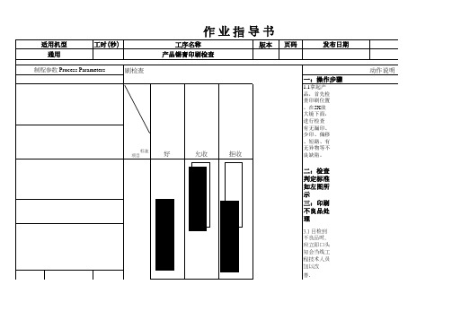
SMT产品锡膏印刷检查作业指导书

工时(秒)
通用 制程参数 Process Parameters
锡膏印 刷检查
标准 项目
作业指导书
工序名称 产品锡膏印刷检查
版本 页码
发布日期
好
允收
拒收
一:操作步骤
1.1拿起产 品,首先检 查印刷位置 。在5X放 大镜下面, 进行检查 有无漏印、 少印、偏移 、短路、有 无异物等不 良缺陷。
二:检查 判定标准 如左图所 示 三:印刷 不良品处 理
3.2 不良品 统一处理, 集中进行清 洗吹干后, 重新进行印 刷. 3.3印刷不 良品,须先 用棉签清理 锡膏,待锡 膏清理干净 后再 用酒精清 洗,再放大 镜检查OK经 IPQC确认后 方可生产.
4.适合机 种
所有产品.
注意事项 Notice
有特殊 要求, 则以客 户文件 为准。
制程特性
符号Symbol
1.重要点: 客户要求的管制点
*
拟定 :_______ _______
审核 :_________ _____
1.作业员必 须佩戴静电 手套或静电 手环。 2.作业员在 检查产品时 勿碰触锡膏 印刷区域。
3.有不良品 洗板时,注 意锡膏不能 沾附于 FPC/PCB上 。
核准 :_______ ________
文件编号 说明
项 Notice
3.1 目检到 不良品时, 应立即口头 知会当线工 程技术人员 加以改
善.
பைடு நூலகம்物料编号
物料名称
用量
文件编号 动作说明
物料编号
物料名称
1
5X放大镜
用量
偏移
无
偏移<1/4 偏移>1/4
《SMT安全规范培训》word版

SMT安全生产注意事项一. 锡膏印刷机使用安全应注意事项.1.锡膏中不含有机溶剂中毒预防规则中所规制的有机溶剂,但锡膏含有金属铅成份,仍应注意避免溶融锡膏所散发气体的吸入. 以及锡膏沾染皮肤, 若有锡膏沾染皮肤, 应立即用含有乙醇的绵花擦拭, 再用肥皂与水冲洗干净; 若有锡膏被揉搓到眼睛内部情况发生, 请立即以清水轻洗患部至少15分钟,并送到医务室请医师检查及治疗处理.2.印刷机所使用网板清洗剂( YC-336 )属于易挥发,易燃液体, 使用时应避免接触火源;清洗剂桶必须放于防爆箱内保存.二. 回焊炉使用安全应注意事项1.回焊炉内部含加热器会产生高温, 在将回焊炉盖掀开时务必用安全插销支撑炉盖(插销具有方向性,长端向上,短端向下), 以防止当气压下降炉盖下压, 造成人身伤害.2. 关闭回流炉,不可迅速切断电源,应逐步冷却,防止轨道变形,作业员被烫伤。
3. 因回焊炉出口的PCB板为高温状态, 当需要接触板子时,须戴耐温手套, 防止被灼伤.实用文档4. 回焊炉运行时炉体中充实惰性气体N2 , 当需要打开炉子密封盖检查时, 应避免将头伸入炉子内部; 以防缺氧状况发生. ( 当出现头晕目眩, 恶心感觉时,请立刻通知同事并离开现场)三. 贴片机设备使用安全应注意事项.1.SMT贴片机属于高速运转设备, 在机器运转时, 禁止作业人员将手或头伸入机台内, 防止造成人员伤亡事故.2.正常生产时, 若需要伸手或头部进入机台检查时, 请将机器的就近紧急保护按钮按下; 然后才能进行检查动作.3.为防止头发被机器运转部位缠绕,而导致事故的发生隐患. 所以要求: SMT作业人员在操作时,必须将头发盘起放入防静电帽中,每日上班时由带线领班检查.4.SMT贴片设备安全门盖上的保护连锁开关, 禁止拆除或屏蔽处理, 违者将给予严厉处分.5.若有发现安全门盖上的保护连锁开关有损坏现象, 请立即通知技术人员维修处理, 以免造成安全隐患.实用文档6. 严禁两人同时操作一台机器。
smt经典培训教材

2、各工序引见:
贴片机的引见
拱架型(Gantry)
元件送料器、基板(PCB)是固定的,贴片头(装置多个真空吸料嘴)在 送料器与基板之间来回移动,将元件从送料器取出,经过对元件位置与 方向的调整,然后贴放于基板上。由于贴片头是装置于拱架型的X/Y坐 标移动横梁上,所以得名。
这类机型的优势在于: 系统结构复杂,可完成高精度,适于各种大小、外形的元件,甚
0.50, 0.65, 0.80, 1.00
Standard type
Ditto, modified leads
Heat resistant type (<64-pin) Heat resistant type (>=64-pin)
144, 176, 208
0.5
1.4mm body thickness
smt经典培训教材
2021/6/30
SMT培训教材
SMT 简介
1、什么是SMT?
Surface mount
Through-hole
SMT:〝Surface Mount Technology 〞的缩写,及外表实装技 术
SMT培训教材
SMT 简介
2、 SMT工艺流程
一、单面组装: 丝印焊膏〔点贴片胶〕=>贴片 =>回流焊接=>检测 =>装箱
这类机型的缺陷在于: 贴装元件类型的限制,并且价钱昂贵。
SMT培训教材
SMT 简介
2、各工序引见:
对元件位置与方向的调整方法:
1)、机械对调整位置、吸嘴旋转调整方向,这种方法能到达的 精度有限,较晚的机型已再不采用。
2)、相机识别、X/Y坐标系统调整位置、吸嘴自动旋转调整方向,相 机固定,贴片头飞行划过相机上空,停止成像识别。
SMT锡膏印刷技术培训讲义

刮板 模板 PCB
焊膏
焊膏在刮板 前滚动前进
产生将焊膏注 Βιβλιοθήκη 漏孔的压力切变力使焊 膏注入漏孔
焊膏释放(脱模) 13
焊膏在刮板前滚动,才能产生将焊膏注入开口的压力
刮板
焊膏
焊膏滚动
印刷时焊膏填充模板开口的情况
脱模 14
开口面积B 开口壁面积A
PCB
图1-4 放大后的焊膏印刷脱模示意图 Fs——焊膏与PCB焊盘之间的粘合力:与开口面积、焊膏黏度有关 Ft——焊膏与开口壁之间的摩檫阻力:与开口壁面积、光滑度有关 A——焊膏与模板开口壁之间的接触面积; B——焊膏与PCB焊盘之间的接触面积(开口面积)
l 如间距为1.3–0.4 mm的J型引脚或翼型引脚元件,通常缩减 量:宽为0.03–0.08 mm,长为0.05–0.13 mm。
(摘录于:IPC-7525 模板设计导则)
用钢板的开口尺寸和形状来减少印刷缺陷
贴片前焊盘
贴片后 易粘连
修改方法1
修改方法2
39
有几种开孔形状有利于锡珠的产生,所有的设计都是为 了能减少锡膏过多地留在元件之下。这些设计通常适用于免 清洗工艺。
b 焊膏质量——焊膏的黏度、印刷性(滚动性、转移性)、触变性、常温 下的使用寿命等都会影响印刷质量。
c 印刷工艺参数——刮刀速度、刮刀压力、刮刀与网板的角度以及焊膏的 黏度之间都存在一定的制约关系,因此只有正确控制这些参数,才能保证焊 膏的印刷质量。
21
d 设备精度方面——在印刷高密度窄间距产品时,印刷机的印刷精度和重 复印刷精度也会起一定的作用。
24
(1)加工合格的模板
1)模板厚度; 2)设计的面积比和宽厚比; 3)开孔的几何形状; 4)开孔孔壁的光滑程度。
SMT锡膏印刷培训讲义(SP60)ppt课件

221~226 227
制程方 式 点胶 网板 钢板
粘度要求(單 位:KCPS)
200-400kcps 400-600kcps 400-1200kcps
按類型分
愈小愈均勻愈好且錫球愈圆愈好,对锡 球滚动较有帮助)。
类型
形狀 直徑um
400
球形
37
500
球形
30
625
球形
20
按清洗方式分
根据焊接過程中所使用的焊劑、焊料成 分來確定。
电木底座(試產)
17
錫膏机印刷過程
錫膏印刷的工作過程主要工序為: 基板輸入→基板定位→图像识別→錫膏印刷→基板輸出
PCB SENSOR
PCB STOP
真空固 定
識別 MARK
Z軸上 升
刮刀下降移動
錫膏填充
刮刀上升
Z軸下降
基板輸 基板從上一站利用輸送帶傳送到印刷机工作平台 入
完成印 刷
基板定 一般在基板與印刷鋼板貼緊的基础來固定基本,常以壓緊基板一份的方式
点击Getnew(Recover Getnew)取出回温,在Scan中输入User ID,在
SN中输入锡膏的序号,在Line 中输入线别在Chksn中输入Get out,
1即.印可刷OK锡,膏列过印程出中序,号印刷机温度必须控制在18℃~24℃,湿度 420.%生~5产0%线RH领环用境锡作膏业前最需好于,不搅可拌用机冷搅风拌或3~热5分风钟直,接具对体著数吹值,溫需度参超考过搅拌 2机6.转6℃速,等會影响錫膏性能。
刮刀清洁步骤、P交C接B执送行进事送项出、步锡骤膏添加作业步骤、
品质异常处理流程、常见故障排除、离岗注意事项、
交接班该执行事项
SMT检验标准培训

1. L2≧L*1/3,OK ; 2. L2<L*1/3,NG .
L2
L
零件间隔
1、两元件之间最小间隔在0.5mm以上为最大允收; 2、两元件之间最小间隔小于0.5mm拒收。
1. 1. W≧0.5mm,OK;
W
2. W<0.5mm,NG
零件直立
零件直立拒收!
零件直立拒收
电容、电感类实装标准模式
D
最小可允收
L W
w1
1. L≧D*25%,OK ; 2. w1≦W*50%, OK .
反之 NG .
二极管偏移
1、二极管突出焊点一端的部分应小于二极管直径的 25%,如果超出二极管直径的25%则拒收。
D W
1. W<D*25%, OK ; 2. W≧D*25%, NG ;
缺口、墓碑、浮高、翻面
NG,拒收
电阻类装配标准模式
按正面贴装,电阻的两端置于基板焊点的中央位置。
OK
电阻偏移(垂直方向)
电阻偏移突出基板焊点的部份是电阻宽度的25% 以下为最大允收限度,如果超过25%则拒收。
W1
W W1≧W*25%,NG.
电阻偏移(水平方向)
1、电阻水平方向偏移,其基板焊点一端的空余长度; 大于或等于另一端空余长度的1/3,为最大允收限度; 如果小于另一端空余长度的1/3则拒收。
(NG)
+
负极
D5 方向
短路 、空焊 、假焊 、冷焊
1、a不同位置两焊点或两导脚间连锡、碰脚为不良; b在不影响外观的前提下,同 一线路两焊点可短路。
2、不允许有空焊,即部品端或导脚与PCB焊点未通过 焊锡连接。 3、 假焊不良。(组件焊端面与PAD未形成金属合金, 施加外力可能使组件松动、 接触不良)
- 1、下载文档前请自行甄别文档内容的完整性,平台不提供额外的编辑、内容补充、找答案等附加服务。
- 2、"仅部分预览"的文档,不可在线预览部分如存在完整性等问题,可反馈申请退款(可完整预览的文档不适用该条件!)。
- 3、如文档侵犯您的权益,请联系客服反馈,我们会尽快为您处理(人工客服工作时间:9:00-18:30)。
同方向匀速约每秒1圈搅拌10分钟
锡膏搅拌拉起呈糊状OK,色泽光亮, 用搅拌到挑起,成线性自由滑落
锡膏搅拌没有达到要求的情况下:
1)印刷时出现在钢网上容易堵塞微小的网孔,下锡不良,直接影响产品品质及效率。 2)锡膏容易变干,直接影响生产效益,浪费生产资源。 3)锡膏原特性质下降,直接影响品质状况及生产效率。
三、锡膏的使用
4. 锡膏的领用: 正常情况下每一条SMT线每次只领用一瓶锡膏,领用锡膏须填写《SMT锡膏出入明
细表》 5. 锡膏的用:
5.1 已开封的锡膏必须在24H内用完,否则需放回冰箱中冷藏。 5.2 首次新锡膏投入量应印刷面积大小而定,且保证锡膏能充分滚动(厚度约5~ 8mm,约为刮刀片高度的2/3),最多不得超过300g。 5.3 在锡膏瓶中取出相应锡膏后,应立即盖上内盖和外盖。 5.4 首次添加到钢网上的锡膏,不得连续使用4小时以上,即在4小时内必须至少添加 2次以上新锡膏。每次添加的锡膏量约为250g以下(≥1/2瓶,组件少的产品,应适当减少 添加量),并且能保证锡膏在钢网上形成良好的滚动印刷性能,添加前须对瓶中的锡膏 进行搅拌( 锡膏机器搅拌时间为3分钟,人工搅拌时间为3-5分钟)。 5.5 一瓶锡膏最多可回冻使用三次,另手机类产品BGA面生产禁止使用回冻锡膏。 6. 锡膏的回收: 6.1 添加到钢网上的锡膏在30分钟内不使用须收回锡膏瓶内保存。 6.2 回收的锡膏超过2小时未投入使用,需将锡膏重新搅拌方可使用。使用的要求为: 相同品牌和相同机型的线别优先使用此回收锡膏。 7. 锡膏的报废: 7.1 开封的锡膏已超过24H,未开封的超过48H且未放回冰箱中冷藏。 7.2 锡膏使用回温次数不可超过3次。
2. 锡膏的分类: 按环保分类为: 有铅锡膏(如:锡铅/锡铅银等)与无铅锡膏(如:锡银铜/锡铜/锡铋等 ) 按使用温度分为: 高如锡铜或锡银铜系/ 常如锡银铋系/ 低温如锡铅铋/ 锡铋等锡膏 按是否需清洗分为: 清洗型和免洗型. 按活性分为: 高RA/中RMA/低R型
3.锡膏的成分及特性: 锡膏是一种均质混合物,由合金焊料粉、糊状悍剂和一些添加剂混合而成的具有一
输存储温度要求。要对锡膏的品牌、型号、有效期及出货检验报告进行检查,保证距 失效期应在三个月内。购买后应放在冰箱中保管储存.密封保存在冰箱0-10℃中,从生 产日起6个月内有效。
1.2 电冰箱温度按每天24H二次记录并绘制控制图填写在《电冰箱温度记录表》上 当冰箱温度超出标准控制温度时,应立即通知工艺工程师或厂务部相关人员处理。
1.3 先入先出锡膏编号管制. 例:入库时间是11年07月18号,则编号为110718001,依此类推。用黑色和绿色颜 色笔按批次标识序号在瓶盖以便识别,最终以编号为准。采用先进先出原则使用。
2. 开封后的锡膏保存: 剩余或使用后的锡膏必须以干净无污染的空瓶封装,要盖上内盖,内盖下推接触到
锡膏面,挤出内盖和锡膏间空气,然后拧紧外盖。如不继续使用,要放回冰箱储存, 不可和新锡膏混合保存,以确保生产品质。
SMT锡膏印刷操作规范及标准检查培训教材
一、锡膏的简介
1.锡膏的简介 2.锡膏的种类 3.锡膏的主要特性及成份 二、锡膏的保存
1.新购锡膏储存 2.开封锡膏的保存 三、锡膏的使用
1.锡膏的回温 2.锡膏使用前的机械搅拌 3.锡膏使用前的手搅拌 4.锡膏的领用 5.锡膏的使用 6.锡膏的回收 7.锡膏的报废 四、印刷前的工作准备
1.PCB领用 2.钢网领用 3.印刷台与钢网定位 4.首件印刷 5.正常印刷 6.钢网清洗 7.刮刀清洗
目录
五、锡膏印刷检验标准 1.CHIP类元件锡膏印刷规格示范 2.SOT类元件类元件锡膏印刷规格示范 3.QFN类元件锡膏印刷规格示范 4.PLCC类元件锡膏印刷规格示范 5.BGA类元件锡膏印刷规格示范 6.锡膏印刷不良与元件焊接造成不良现象 7. Chip料锡膏厚度外观 8. SOT料锡膏厚度外观 9. QFN料锡膏厚度外观 10. PLCC料锡膏厚度外观 11. BGA料锡膏厚度外观
三、锡膏的使用
1. 锡膏的回温:
保证“先进先出”原则,从冰箱取出需用的锡膏需回温,放置解冻区解冻4小时。 锡膏从冰箱取出时,其温度较室温低很多,若未经回温而开启瓶盖,则容易将空气中 的水汽凝结,并粘附于锡浆上,在过回流焊时,水份因受强热而迅速液化,造成“锡 爆”现象产生锡珠,甚至损坏器件。因此锡膏使用前,应先从冷藏室中取出,在不开 起瓶盖的前提下放置在阴凉处(禁止使用其他加热器使其温度瞬间上升的做法),室 温下回温4小时后才可正常使用。并在标签栏记录开始解冻时间,注意未经充足回温时 间的锡膏千万不要打开瓶盖。未开封的锡膏在常温下可存放48H(起始时间从冰箱内取 出开始计算),如超过48H需拿回冰箱冷藏.回温后的锡膏,必须在48小时内上线使用。
一、锡膏的简介
1. 锡膏的简介: solder paster也称焊锡膏,灰色或灰白色膏体,比重界乎:7.2-8.5,一般为五百克密封
瓶装,也有特别定做的如针筒包装或一公斤包装,与传统焊锡膏相比,多了金属成分.于零 到十度间低温保存(五至七度最佳),日前也有常温保存锡膏面市,效果仍不甚理想通常使 用3#粉径(25-45微米)之合金粉(因不同需要也有可能用到更细如4#及2.3#粗粉)与百分 之八到十二的助焊膏在真空(氮气保护)环境之均速搅拌而成。
编号定义:A20110708-140 "A"代表有铅锡膏,"B"代表无铅锡膏
“20110708”代表年月日 “140”代表流水号
三、锡膏的使用
2. 使用前的机械搅拌: 锡膏使用前应该充分搅拌,旋紧瓶盖,把整瓶锡膏放进机器内的固定位置上,设置
时间3分钟,均匀搅拌。
锡膏
搅拌机
三、锡膏的使用
3. 使用前的手搅拌: 锡膏使用前应充分搅拌,用塑胶刮刀顺时针搅拌,以减少锡粉的沉淀,一直到锡膏
定粘性和良好触变性的膏状体。在常温下,焊膏可将元器件初粘在既定位置,当被加 热到一定温度时(有铅183度,无铅217度)随着溶剂和部分添加剂的挥发,合金粉的 融化,使被焊元器件和焊盘连在一起,冷却形成永久连接的焊点。
二、锡膏的保存
1. 新购锡膏之储存: 1.1 锡膏供应商送货时,必须采用密封保温封装或放入冷藏箱内,确保符合短期运
