Mitra《数字信号处理-基于计算机的方法》翻译 武汉大学 孙洪
《数字信号处理》 完整加精版

采用抽象算法表达:由软件程序虚拟实现。 在采用硬件电路实现时,由于不需要考虑 物理环境对信号的影响,可以在设计中尽可
能采用低功耗高密度集成。
数字系统的特点
信号采用数字序列表达后,对模拟信号难以 进行的很多处理能够方便地实现,例如: 对信号的乘法调制和各种编码调制、信号的时 间顺序处理、信号的时间压缩/扩张、复杂标准 信号的产生…
时间变量与对应的函数值采用两个相等长度的序列 (一维向量)表示。 两个序列可以进行直接数值设臵:
例:n=[0 1 2 3 4 5 6 7];
x=[1 2 4 6 5 3 1 0];
数字信号的MATLAB表达
坐标区间设臵: n=[n1:n2] 只取整数,设定起点和终点;
信号函数设臵:其序列长度由n序列限定; x=3*n x=exp(j*(pi/8)*n)
设臵好坐标序列t和信号序列x后,可以采 用下列作图语句画出连续时间信号图形: plot(t,x) 该语句通过将离散的信号点之间用直线连 接得到连续图形。
模拟信号的作图表达
例:MATLAB程序
t=[0:0.1:10];x1=[zeros(1,30) ones(1,40) zeros(1,31)]; x2=2-0.3*t;x3=exp(j*(pi/8)*t);x4=exp(-0.2*t).*cos(2*pi*t);
欠采样导致的问题
s N
若原始频谱与镜像频谱混叠,产生混叠失真,则
信号不可恢复!
采样定理
待采样信号必须为带限信号
X 0
M
采样频率应大于信号最高频率的2倍
2 s 2M N Ts
Nyquist 频率
重建滤波器(低通)截止频率应满足:
2013Mitra_Chapter_1

朱丽平通信工程系(理工楼214房间)zlp6681@数字信号处理(Digital Signal Processing)关于本课程(About the course)教材¾数字信号处理——基于计算机的方法(第四版). Sanjit K. Mitra著,余翔宇译. 电子工业出版社. 2012,1.¾数字信号处理实验指导书(MATLAB 版). Sanjit K. Mitra 著,孙洪等译. 电子工业出版社. 2005, 1.参考书¾Richard G. Lyons. Understanding Digital Signal Processing(Second Edition). 机械工业出版社. 2005,1.¾朱光明,程建远,刘保童等译. 数字信号处理(原书第2版). 机械工业出版社. 2006,1.评分标准平时:出勤(10%) + 作业(10%) + 实验报告(10%)阶段测试:理论(20%) + 实验(20%) 期末考试: 30%课程体系(Architecture of the course)数字信号处理信号处理与算法实现系统分析、设计与实现数字滤波器结构(直接型、级联型、并联型、格型)数字滤波器实现中的有限字长效应离散时间信号的时频域变换(DTFT 、DFT 、STFT 、DCT 、z 变换)数字滤波器设计(IIR 、FIR)离散时间系统的时域分析离散时间信号的时域分析离散时间信号的频域分析快速算法(FFT)离散时间系统的变换域分析课程内容(Contents of the course)第1章信号和信号处理第2章时域中的离散时间信号 第3章频域中的离散时间信号 第4章离散时间系统 第5章有限长离散变换第7章变换域中的LTI 离散时间系统 第8章数字滤波器结构 第9章IIR 数字滤波器设计 第10章FIR 数字滤波器设计 第11章DFT 算法实现第12章有限字长效应的分析Matlab 实验(Laboratory Using Matlab)Lab 1 Discrete-Time Signals : Time-Domain Representations (离散时间信号的时域分析) Lab 2 Discrete-Time Systems : Time-Domain Representations (离散时间系统的时域分析) Lab3 Discrete-Time Signals : Frequency-Domain Representations (离散时间信号的频域分析)Lab 4 Digital Processing of Continuous-Time Signals (连续时间信号的数字处理)Lab 5 Digital Filter Design (数字滤波器设计) Lab 6 Digital Filter Implementation (数字滤波器实现)信号和信号处理(Signals and Signal Processing)第1章学习目标(Learning Objectives)信号的特征与分类(Characterization and Classification of Signals)典型的信号处理运算(Typical signal processing operations)典型信号举例(Examples of Typical Signals) 为什么要进行数字信号处理(Why digital signal processing)数字信号处理的实现(Implementations of Digital Signal Processing)1.1 信号的特征与分类continuous-time signal (连续时间信号)模拟信号量化阶梯信号discrete-time signal (离散时间信号)采样信号数字信号1.2 典型的信号处理运算时域基本运算(Simple Time-DomainOperations) 滤波(Filtering)复用和解复用(Multiplexing and Demultiplexing)信号的产生(Signal Generation)1.2.1 时域基本运算t 0 >0, delay (延时)t 0 <0, advance (超前)()x t ()()y t x t α=α为正的或负的常数.α 标乘(scaling)()x t ()()0y t x t t =−相加(addition)()a t ()()()y t a t x t =相乘(product)()1x t ()2x t ()()()12y t x t x t =+ 1.2.1 时域基本运算differentiation (微分)integration (积分)()x t ()()ty t x d ττ−∞=∫∫()x t d dt()()dx t y t dt=1.2.2 滤波()()j t X j x t e dt∞−Ω−∞Ω=∫():x t 连续时间信号the spectrum of x(t),x(t)的频谱()?X j Ω滤波的目的:根据指定的要求改变频谱。
现代信号处理大作业题目+答案

研究生“现代信号处理”课程大型作业(以下四个题目任选三题做)1. 请用多层感知器(MLP )神经网络误差反向传播(BP )算法实现异或问题(输入为[00;01;10;11]X T =,要求可以判别输出为0或1),并画出学习曲线。
其中,非线性函数采用S 型Logistic 函数。
2. 试用奇阶互补法设计两带滤波器组(高、低通互补),进而实现四带滤波器组;并画出其频响。
滤波器设计参数为:F p =1.7KHz , F r =2.3KHz , F s =8KHz , A rmin ≥70dB 。
3. 根据《现代数字信号处理》(姚天任等,华中理工大学出版社,2001)第四章附录提供的数据(pp.352-353),试用如下方法估计其功率谱,并画出不同参数情况下的功率谱曲线:1) Levinson 算法2) Burg 算法3) ARMA 模型法4) MUSIC 算法4. 图1为均衡带限信号所引起失真的横向或格型自适应均衡器(其中横向FIR 系统长M =11), 系统输入是取值为±1的随机序列)(n x ,其均值为零;参考信号)7()(-=n x n d ;信道具有脉冲响应:12(2)[1cos()]1,2,3()20 n n h n W π-⎧+=⎪=⎨⎪⎩其它式中W 用来控制信道的幅度失真(W = 2~4, 如取W = 2.9,3.1,3.3,3.5等),且信道受到均值为零、方差001.02=v σ(相当于信噪比为30dB)的高斯白噪声)(n v 的干扰。
试比较基于下列几种算法的自适应均衡器在不同信道失真、不同噪声干扰下的收敛情况(对应于每一种情况,在同一坐标下画出其学习曲线):1) 横向/格-梯型结构LMS 算法2) 横向/格-梯型结构RLS 算法并分析其结果。
图1 横向或格-梯型自适应均衡器参考文献[1] 姚天任, 孙洪. 现代数字信号处理[M]. 武汉: 华中理工大学出版社, 2001[2] 杨绿溪. 现代数字信号处理[M]. 北京: 科学出版社, 2007[3] S. K. Mitra. 孙洪等译. 数字信号处理——基于计算机的方法(第三版)[M]. 北京: 电子工业出版社, 2006[4] S.Haykin, 郑宝玉等译. 自适应滤波器原理(第四版)[M].北京: 电子工业出版社, 2003[5] J. G. Proakis, C. M. Rader, F. Y. Ling, etc. Algorithms for Statistical Signal Processing [M].Beijing: Tsinghua University Press, 2003一、请用多层感知器(MLP)神经网络误差反向传播(BP)算法实现异或问题(输入为[00;01;10;11],要求可以判别输出为0或1),并画出学习曲线。
专业英语翻译之数字信号处理

Signal processingSignal processing is an area of electrical engineering and applied mathematics that deals with operations on or analysis of signals, in either discrete or continuous time, to perform useful operations on those signals. Signals of interest can include sound, images, time-varying measurement values and sensor data, for example biological data such as electrocardiograms, control system signals, telecommunication transmission signals such as radio signals, and many others. Signals are analog or digital electrical representations of time-varying or spatial-varying physical quantities. In the context of signal processing, arbitrary binary data streams and on-off signalling are not considered as signals, but only analog and digital signals that are representations of analog physical quantities.HistoryAccording to Alan V. Oppenheim and Ronald W. Schafer, the principles of signal processing can be found in the classical numerical analysis techniques of the 17th century. They further state that the "digitalization" or digital refinement of these techniques can be found in the digital control systems of the 1940s and 1950s.[2]Categories of signal processingAnalog signal processingAnalog signal processing is for signals that have not been digitized, as in classical radio, telephone, radar, and television systems. This involves linear electronic circuits such as passive filters, active filters, additive mixers, integrators and delay lines. It also involves non-linear circuits such ascompandors, multiplicators (frequency mixers and voltage-controlled amplifiers), voltage-controlled filters, voltage-controlled oscillators andphase-locked loops.Discrete time signal processingDiscrete time signal processing is for sampled signals that are considered as defined only at discrete points in time, and as such are quantized in time, but not in magnitude.Analog discrete-time signal processing is a technology based on electronic devices such as sample and hold circuits, analog time-division multiplexers, analog delay lines and analog feedback shift registers. This technology was a predecessor of digital signal processing (see below), and is still used in advanced processing of gigahertz signals.The concept of discrete-time signal processing also refers to a theoretical discipline that establishes a mathematical basis for digital signal processing, without taking quantization error into consideration.Digital signal processingDigital signal processing is for signals that have been digitized. Processing is done by general-purpose computers or by digital circuits such as ASICs, field-programmable gate arrays or specialized digital signal processors (DSP chips). Typical arithmetical operations include fixed-point and floating-point, real-valued and complex-valued, multiplication and addition. Other typical operations supported by the hardware are circular buffers and look-up tables. Examples of algorithms are the Fast Fourier transform (FFT), finite impulseresponse (FIR) filter, Infinite impulse response (IIR) filter, and adaptive filters such as the Wiener and Kalman filters1.Digital signal processingDigital signal processing (DSP) is concerned with the representation of signals by a sequence of numbers or symbols and the processing of these signals. Digital signal processing and analog signal processing are subfields of signal processing. DSP includes subfields like: audio and speech signal processing, sonar and radar signal processing, sensor array processing, spectral estimation, statistical signal processing, digital image processing, signal processing for communications, control of systems, biomedical signal processing, seismic data processing, etc.The goal of DSP is usually to measure, filter and/or compress continuousreal-world analog signals. The first step is usually to convert the signal from an analog to a digital form, by sampling it using an analog-to-digital converter (ADC), which turns the analog signal into a stream of numbers. However, often, the required output signal is another analog output signal, which requires a digital-to-analog converter (DAC). Even if this process is more complex than analog processing and has a discrete value range, the application of computational power to digital signal processing allows for many advantages over analog processing in many applications, such as error detection and correction in transmission as well as data compression.[1]DSP algorithms have long been run on standard computers, on specialized processors called digital signal processors (DSPs), or on purpose-built hardware such as application-specific integrated circuit (ASICs). Today thereare additional technologies used for digital signal processing including more powerful general purpose microprocessors, field-programmable gate arrays (FPGAs), digital signal controllers (mostly for industrial apps such as motor control), and stream processors, among others.[2]2. DSP domainsIn DSP, engineers usually study digital signals in one of the following domains: time domain (one-dimensional signals), spatial domain (multidimensional signals), frequency domain, autocorrelation domain, and wavelet domains. They choose the domain in which to process a signal by making an informed guess (or by trying different possibilities) as to which domain best represents the essential characteristics of the signal. A sequence of samples from a measuring device produces a time or spatial domain representation, whereas a discrete Fourier transform produces the frequency domain information, that is the frequency spectrum. Autocorrelation is defined as the cross-correlation of the signal with itself over varying intervals of time or space.3. Signal samplingMain article: Sampling (signal processing)With the increasing use of computers the usage of and need for digital signal processing has increased. In order to use an analog signal on a computer it must be digitized with an analog-to-digital converter. Sampling is usually carried out in two stages, discretization and quantization. In the discretization stage, the space of signals is partitioned into equivalence classes and quantization is carried out by replacing the signal with representative signal of the corresponding equivalence class. In the quantization stage the representative signal values are approximated by values from a finite set.The Nyquist–Shannon sampling theorem states that a signal can be exactly reconstructed from its samples if the sampling frequency is greater than twice the highest frequency of the signal; but requires an infinite number of samples . In practice, the sampling frequency is often significantly more than twice that required by the signal's limited bandwidth.A digital-to-analog converter is used to convert the digital signal back to analog. The use of a digital computer is a key ingredient in digital control systems. 4. Time and space domainsMain article: Time domainThe most common processing approach in the time or space domain is enhancement of the input signal through a method called filtering. Digital filtering generally consists of some linear transformation of a number of surrounding samples around the current sample of the input or output signal. There are various ways to characterize filters; for example:• A "linear" filter is a linear transformation of input samples; other filters are "non-linear". Linear filters satisfy the superposition condition, i.e. if an input is a weighted linear combination of different signals, the output is an equally weighted linear combination of the corresponding output signals.• A "causal" filter uses only previous samples of the input or output signals; while a "non-causal" filter uses future input samples. A non-causal filter can usually be changed into a causal filter by adding a delay to it.• A "time-invariant" filter has constant properties over time; other filters such as adaptive filters change in time.•Some filters are "stable", others are "unstable". A stable filter produces an output that converges to a constant value with time, or remains bounded within a finite interval. An unstable filter can produce an output that grows without bounds, with bounded or even zero input.• A "finite impulse response" (FIR) filter uses only the input signals, while an "infinite impulse response" filter (IIR) uses both the input signal and previous samples ofthe output signal. FIR filters are always stable, while IIR filters may be unstable.Filters can be represented by block diagrams which can then be used to derive a sample processing algorithm to implement the filter using hardware instructions. A filter may also be described as a difference equation, a collection of zeroes and poles or, if it is an FIR filter, an impulse response or step response.The output of a digital filter to any given input may be calculated by convolving the input signal with the impulse response.5. Frequency domainMain article: Frequency domainSignals are converted from time or space domain to the frequency domain usually through the Fourier transform. The Fourier transform converts the signal information to a magnitude and phase component of each frequency. Often the Fourier transform is converted to the power spectrum, which is the magnitude of each frequency component squared.The most common purpose for analysis of signals in the frequency domain is analysis of signal properties. The engineer can study the spectrum todetermine which frequencies are present in the input signal and which are missing.In addition to frequency information, phase information is often needed. This can be obtained from the Fourier transform. With some applications, how the phase varies with frequency can be a significant consideration.Filtering, particularly in non-realtime work can also be achieved by converting to the frequency domain, applying the filter and then converting back to the time domain. This is a fast, O(n log n) operation, and can give essentially any filter shape including excellent approximations to brickwall filters.There are some commonly used frequency domain transformations. For example, the cepstrum converts a signal to the frequency domain through Fourier transform, takes the logarithm, then applies another Fourier transform. This emphasizes the frequency components with smaller magnitude while retaining the order of magnitudes of frequency components.Frequency domain analysis is also called spectrum- or spectral analysis.6. Z-domain analysisWhereas analog filters are usually analysed on the s-plane; digital filters are analysed on the z-plane or z-domain in terms of z-transforms.Most filters can be described in Z-domain (a complex number superset of the frequency domain) by their transfer functions. A filter may be analysed in the z-domain by its characteristic collection of zeroes and poles.7. ApplicationsThe main applications of DSP are audio signal processing, audio compression, digital image processing, video compression, speech processing, speech recognition, digital communications, RADAR, SONAR, seismology, and biomedicine. Specific examples are speech compression and transmission in digital mobile phones, room matching equalization of sound in Hifi and sound reinforcement applications, weather forecasting, economic forecasting, seismic data processing, analysis and control of industrial processes, computer-generated animations in movies, medical imaging such as CAT scans and MRI, MP3 compression, image manipulation, high fidelity loudspeaker crossovers and equalization, and audio effects for use with electric guitar amplifiers8. ImplementationDigital signal processing is often implemented using specialised microprocessors such as the DSP56000, the TMS320, or the SHARC. These often process data using fixed-point arithmetic, although some versions are available which use floating point arithmetic and are more powerful. For faster applications FPGAs[3] might be used. Beginning in 2007, multicore implementations of DSPs have started to emerge from companies including Freescale and Stream Processors, Inc. For faster applications with vast usage, ASICs might be designed specifically. For slow applications, a traditional slower processor such as a microcontroller may be adequate. Also a growing number of DSP applications are now being implemented on Embedded Systems using powerful PCs with a Multi-core processor.(翻译)信号处理信号处理是电气工程与应用数学领域,在离散的或连续时间域处理和分析信号,以对这些信号进行所需的有用的处理。
数字信号处理 国外教材
数字信号处理国外教材数字信号处理(Digital Signal Processing,DSP)是指通过数字计算机对信号进行采样、量化、编码、处理和解码的技术过程。
它已经成为现代通信、图像处理、音频处理和控制系统等领域中不可或缺的核心技术。
国外教材在数字信号处理方面具有丰富的资源和深厚的研究成果,以下将介绍一些常见的国外数字信号处理教材。
1. 《数字信号处理:原理、算法与硬件实现》(Digital Signal Processing: Principles, Algorithms, and Applications)- John G. Proakis, Dimitris G. Manolakis这是一本经典的数字信号处理教材,适用于本科和研究生的学习。
它全面介绍了数字信号处理的原理、算法和实现方法,并包含了大量的数学推导和实际应用。
该书广泛探讨了滤波器设计、频谱分析、傅里叶变换、数字滤波器设计和信号重建等主题。
2. 《数字信号处理和系统》(Digital Signal Processing and System)- Gérard Blanchet, Maurice Charbit这本教材介绍了数字信号处理的基本概念和技术,并重点介绍了系统建模、滤波器设计和频谱分析等内容。
它以实际的案例和应用为基础,帮助学习者理解数字信号处理在实际系统中的应用。
该书还包含了大量的练习题和实验,帮助学习者深入理解和应用所学知识。
3. 《数字信号处理系统设计与实现》(Digital Signal Processing System Design and Implementation)- Sanjit K.Mitra这本教材侧重于数字信号处理系统的设计和实现,包括硬件和软件方面的内容。
它详细介绍了数字信号处理器(DSP)的体系结构和特点,并着重讨论了DSP算法的设计和优化。
该书以实际应用为导向,涵盖了多种领域中的案例研究,如音频信号处理、图像处理和通信系统等。
Lecture 1 数字信号处理概述,华工数字信号处理课件,DSP

计算能力(MIPS )
5,40,200,5000,8000 50000? MIPS: Million Instructions Per Second
计算能力(主频 )
5MHz,到100MHz、200MHz 、1.1Ghz ?
考核方式
考核方式
期末考试:70%~80% 平时作业:20%~30%
课程宗旨
突出基本概念及原理算法 清晰理论及关键技术应用背景 强调理论联系实践
结合Matlab或C/C++,加强练习
Practice Makes Perfect
结合学科发展进行有特色的讲座式授课 创新型人才培养
DSP(processing) vs. DSP(processor)
数字信号处理是分析处理数字信号的一门科学, DSP将信号离散数字化表示,通过计算处理设备, 用数值计算方法进行各种处理,达到提取有用信息 便于应用的目的。常用的处理方法有:
AD/DA,滤波、检测、变换、编码、压缩、增强、估计、
的定义
A special-purpose CPU used for digital
signal processing applications. It provides ultra-fast instruction sequences, such as shift and add, and multiply and add, which are commonly used in math-intensive signal processing. DSP chips are widely used in a myriad of devices, including cell-phones, sound cards, fax machines, modems, hard disks and digital TVs. The first DSP chip used in a commercial product was believed to be in the very popular Speak & Spell game, introduced by TI(Texas Instruments) in the late 1970s.
数字信号处理中英文对照外文翻译文献
中英文对照外文翻译(文档含英文原文和中文翻译)数字信号处理一、导论数字信号处理(DSP)是由一系列的数字或符号来表示这些信号的处理的过程的。
数字信号处理与模拟信号处理属于信号处理领域。
DSP包括子域的音频和语音信号处理,雷达和声纳信号处理,传感器阵列处理,谱估计,统计信号处理,数字图像处理,通信信号处理,生物医学信号处理,地震数据处理等。
由于DSP的目标通常是对连续的真实世界的模拟信号进行测量或滤波,第一步通常是通过使用一个模拟到数字的转换器将信号从模拟信号转化到数字信号。
通常,所需的输出信号却是一个模拟输出信号,因此这就需要一个数字到模拟的转换器。
即使这个过程比模拟处理更复杂的和而且具有离散值,由于数字信号处理的错误检测和校正不易受噪声影响,它的稳定性使得它优于许多模拟信号处理的应用(虽然不是全部)。
DSP算法一直是运行在标准的计算机,被称为数字信号处理器(DSP)的专用处理器或在专用硬件如特殊应用集成电路(ASIC)。
目前有用于数字信号处理的附加技术包括更强大的通用微处理器,现场可编程门阵列(FPGA),数字信号控制器(大多为工业应用,如电机控制)和流处理器和其他相关技术。
在数字信号处理过程中,工程师通常研究数字信号的以下领域:时间域(一维信号),空间域(多维信号),频率域,域和小波域的自相关。
他们选择在哪个领域过程中的一个信号,做一个明智的猜测(或通过尝试不同的可能性)作为该域的最佳代表的信号的本质特征。
从测量装置对样品序列产生一个时间或空间域表示,而离散傅立叶变换产生的频谱的频率域信息。
自相关的定义是互相关的信号本身在不同时间间隔的时间或空间的相关情况。
二、信号采样随着计算机的应用越来越多地使用,数字信号处理的需要也增加了。
为了在计算机上使用一个模拟信号的计算机,它上面必须使用模拟到数字的转换器(ADC)使其数字化。
采样通常分两阶段进行,离散化和量化。
在离散化阶段,信号的空间被划分成等价类和量化是通过一组有限的具有代表性的信号值来代替信号近似值。
武汉大学数字信号处理课件ch01

数字信号处理实际系统并不一定要包括它的所有框如有些系统只需数字输出,可直接以数另一些系统的输入就是数字量,因而就纯数字系统则只需要数字信号处理器这在国际上一般把而它的历史可以追溯到数字信号处理的基本工具:微积分,概数字信号处理的理论基础:离散线性变在学科发展上,数字信号处理又和最优数字信号处理学科包含有与模拟系统1234567在模拟系统中,它的精度是由元件决2.可靠性强模拟系统:各参数都有一定的温度系数,易受环境条件,如温度、振动、电磁感应等影响,产生杂散效应甚至振荡等数字系统:只有两个信号电平0,1受噪声及环境条件等影响小。
且数字系统采用大规模集成电路,其故障率远远小于采用众多分立元件构成的模拟系统数字系统的性能主要决定于乘法器的各利用某一路信号的相邻两抽样值之间存在很大的空隙例:对信号进行频谱分析模拟频谱仪在频率低端只能分析到但在数字的谱分析中,已能做到又例:有限长冲激响应数字滤波器,则可实现利用庞大的存储单元,可以存储一帧或数字系统的速度还不算高,因而不能处另外,数字系统的设计和结构复杂,价数字系统由有源器件构成自数字信号处理大致可分为:信号分析信号滤波它是最早采用数字信号处理技术的领域之一。
本世纪在语音领域现存在着三种系统:即广泛应用于电话窃听。
应用于语音编码、语音合在GSM手机中用DSP可将语音压缩数字信号处理技术成功应用的图像处理方法数据压缩图像复原清晰化与增强采用DSP完成视频图像信号的压缩整个通信领域几乎没有不受数字信号处理数字技术已用于信号的调制、解调、滤语音数据压缩与解压是数字信号处理的重在电信领域,数字处理技术已发展到音调利用通信卫星打越洋长途电话时调制解调器下面介绍它们在通讯中的应用大家知道,脉与数据压缩相反的数据扩张,也是很有用的技现代通信系统是信息时代的生命线。
最生物医学信号处理CTCAT:1. 2. 3. 4.工作站和微机上各厂家的数字信号软用这一方法优点:可适用于各种数字信由于单片机发展已经很久,价格便宜,优点:可根据不同环境配不同单片机,DSP如内部带有乘法器,累加器,采用流水线目前市场上的美国德州仪器公司还有MotorolaAD市场上推出专门用于如:National其软件算法已在芯片内部用硬件电路实现,使数字信号处理技术已经成熟DSP。
现代信号处理大作业
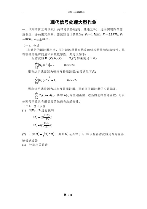
现代信号处理大型作业一.试用奇阶互补法设计两带滤波器组(高、低通互补),进而实现四带滤波器组;并画出其频响。
滤波器设计参数为:F p =1.7KHz , F r =2.3KHz , F s =8KHz , A rmin ≥70dB 。
(一)、分析与通常的滤波器相比,互补滤波器具有优良的结构特性和结构特性,具有较低的噪声能量和系数敏感性,其定义如下:一组滤波器H 12(),(),.......()Z H Z H Z n 如果满足下式:He Kjw k n(),==∑110<w<2π 则称这组滤波器为幅度互补滤波器;如果满足下式:He kjw k n()=∑=121, 0<w<2π则称这组滤波器为功率互补滤波器,同时互补滤波器还应该满足:Hz A z kk n()()=∑=1其中A(z)为全通函数,适当的选择全通函数,可以使两带函数具有所需要的低通和高通特性。
(二)、设计步骤(1) 对Fp 、Fr 进行预畸);();(''FsFrtg FsFptg r p ∏=Ω∏=Ω(2) 计算'''*r p c ΩΩ=Ω,判断'c Ω是否等于1,即该互补滤波器是否为互补镜像滤波器(3) 计算相关系数⎪⎩⎪⎨⎧-==+++=+-=-=ΩΩ=--=偶数)N 为(;21奇数)N 为 (;;lg /)16/1lg(;150152;1121;1;;])110)(110[(1213090500''02'''211-min1.0min1.0i i u q k N q q q q q k k q k k k k rp Ar Ap;)2cos()1(21))12(sin()1(21)1(21'2∑∑∞=∞=+-++-=Ωm mm m m m m i u Nm q u Nm q q ππ;42⎥⎦⎤⎢⎣⎡=N N;221N N N -⎥⎦⎤⎢⎣⎡=;)/1)(1(2'2'k k v i i i Ω-Ω-=12'1212,1;12N i v i i i =Ω+=--α 22'22,1;12N i v iii =Ω+=β (4) 互补镜像滤波器的数字实现;22i ii A αα+-=;22iii B ββ+-=1221,1;1)(N i ZA Z A Z H i i i =++=∏--22212,1;1)(N i ZB Z B Z Z H i i i =++=∏--- )];()([21)(21Z H Z H Z H L +=(三)、程序与结果 1. 二带滤波器组 (1) 源程序: clear; clf;Fp=1700;Fr=2300;Fs=8000; Wp=tan(pi*Fp/Fs); Wr=tan(pi*Fr/Fs); Wc=sqrt(Wp*Wr); k=Wp/Wr;k1=sqrt(sqrt(1-k^2)); q0=0.5*(1-k1)/(1+k1);q=q0+2*q0^5+15*q0^9+150*q0^13; N=11;N2=fix(N/4); M=fix(N/2); N1=M-N2; for jj=1:M a=0;for m=0:5a=a+(-1)^m*q^(m*(m+1))*sin((2*m+1)*pi*jj/N);%N is odd, u=j end ab=0;for m=1:5b=b+(-1)^m*q^(m^2)*cos(2*m*pi*jj/N); end bW(jj)=2*q^0.25*a/(1+2*b);V(jj)=sqrt((1-k*W(jj)^2)*(1-W(jj)^2/k)); endfor i=1:N1alpha(i)=2*V(2*i-1)/(1+W(2*i-1)^2); endfor i=1:N2beta(i)=2*V(2*i)/(1+W(2*i)^2); endfor i=1:N1a(i)=(1-alpha(i)*Wc+Wc^2)/(1+alpha(i)*Wc+Wc^2); endfor i=1:N2b(i)=(1-beta(i)*Wc+Wc^2)/(1+beta(i)*Wc+Wc^2); endw=0:0.0001:0.5;LP=zeros(size(w));HP=zeros(size(w));for n=1:length(w)z=exp(j*w(n)*2*pi);H1=1;for i=1:N1H1=H1*(a(i)+z^(-2))/(1+a(i)*z^(-2)) ;endH2=1/z;for i=1:N2H2=H2*(b(i)+z^(-2))/(1+b(i)*z^(-2));endLP(n)=abs((H1+H2)/2);HP(n)=abs((H1-H2)/2);endplot(w,LP,'b',w,HP,'r');hold on;xlabel('digital frequency');ylabel('amptitude');(2)运行结果:见图1图1 二带数字滤波器组2.四带滤波器组(1)源程序:clf;Fp=1700;Fr=2300;Fs=8000;Wp=tan(pi*Fp/Fs);Wr=tan(pi*Fr/Fs);Wc=sqrt(Wp*Wr);k=Wp/Wr;k1=sqrt(sqrt(1-k^2));q0=0.5*(1-k1)/(1+k1);q=q0+2*q0^5+15*q0^9+150*q0^13;N=11;N2=fix(N/4);M=fix(N/2);N1=M-N2;for jj=1:Ma=0;for m=0:5a=a+(-1)^m*q^(m*(m+1))*sin((2*m+1)*pi*jj/N); % N is odd, u=jendb=0;for m=1:5b=b+(-1)^m*q^(m^2)*cos(2*m*pi*jj/N);endW(jj)=2*q^0.25*a/(1+2*b);V(jj)=sqrt((1-k*W(jj)^2)*(1-W(jj)^2/k));Endfor i=1:N1alpha(i)=2*V(2*i-1)/(1+W(2*i-1)^2);endfor i=1:N2beta(i)=2*V(2*i)/(1+W(2*i)^2);endfor i=1:N1a(i)=(1-alpha(i)*Wc+Wc^2)/(1+alpha(i)*Wc+Wc^2);endfor i=1:N2b(i)=(1-beta(i)*Wc+Wc^2)/(1+beta(i)*Wc+Wc^2);endw=0:0.0001:0.5;LLP=zeros(size(w));LHP=zeros(size(w));HLP=zeros(size(w));HHP=zeros(size(w));for n=1:length(w)z=exp(j*w(n)*2*pi);H1=1;for i=1:N1H1=H1*(a(i)+z^(-2))/(1+a(i)*z^(-2)) ;endH21=1;for i=1:N1H21=H21*(a(i)+z^(-4))/(1+a(i)*z^(-4)) ;H2=1/z;for i=1:N2H2=H2*(b(i)+z^(-2))/(1+b(i)*z^(-2));endH22=1/(z^2);for i=1:N2H22=H22*(b(i)+z^(-4))/(1+b(i)*z^(-4));endLP=((H1+H2)/2);HP=((H1-H2)/2);LLP(n)=abs((H21+H22)/2*LP);LHP(n)=abs((H21-H22)/2*LP);HHP(n)=abs((H21+H22)/2*HP);HLP(n)=abs((H21-H22)/2*HP);endplot(w,LLP,'b',w,LHP,'r',w,HLP,'k',w,HHP,'m')hold onxlabel('digital frequency');ylabel('amptitude');(2)运行结果:见图2图2 四带数字滤波器组二、根据《现代数字信号处理》第四章提供的数据,试用如下方法估计其功率谱,并画出不同参数情况下的功率谱曲线:1)Levison算法2)Burg算法3) ARMA 模型法 4) MUSIC 算法 1 Levinson 算法Levinson 算法用于求解Yule-Walker 方程,是一种按阶次进行递推的算法,即首先以AR (0)和AR (1)模型参数作为初始条件,计算AR (2)模型参数;然后根据这些参数计算AR (3)参数,等等,一直到计算出AR (p )模型参数为止,需要的运算量数量级为2p ,其中p 为AR 模型的阶数。
成都电子科技大学研究生新生跨学科考生补修本科核心课程统计表(最终版)
007
081100
控制科学与工程
信号与系统
007
085203
仪器仪表工程
电子测量原理
007
085210
控制工程(控制方向)
信号与系统
009
071006
神经生物学
神经解剖学
009
071010
生物化学与分子生物学
遗传学
009
071011
生物物理学
大学物理
009
083100
生物医学工程
数字信号处理
《现代医学电子仪器原理与设计》余学飞 华南 生物医学仪器原 理工大学出版社 2007年第2版 理 《现代医学电子仪器原理与设计》余学飞 华南 生物医学仪器原 理工大学出版社 2007年第3版 理 高等代数 作者:北大数学系 出版社:高等教育出版社
课程三
参考书目三(包括作者 、出版社、出版年份)
《电子测量原理》古天祥 王厚军等主编 机械工 自动测试系统 业出版社 2004 《信号与系统》(第2版)陈后金 胡健 薛健主 自动控制原理 编 清华大学出版社 2003 《电子测量原理》古天祥 王厚军等主编 机械工 自动测试系统 业出版社 2004 《信号与系统》(第2版)陈后金 胡健 薛健主 自动控制原理 编 清华大学出版社 2003 《神经解剖学》蒋文华 复旦大学出版社 2011年 生理学 Essentials of Genetics Klug WS 高等教育出 生物制药技术 版社 2008 《普通物理学》(第五版) 程守洙 高等教育出版 生理学 社 2003年 《数字信号处理-基于计算机的方法》(第三 版) Sanjit K. Mitra著 孙洪译 2007 《数字信号处理-基于计算机的方法》(第三 版) Sanjit K. Mitra著 孙洪译 2007 作者:陈记修等 出版社:高等教育出版社
数字信号处理英文翻译
英文原文The simulation and the realization of the digital filter With the information age and the advent of the digital world, digital signal processing has become one of today's most important disciplines and door technology. Digital signal processing in communications, voice, images, automatic control, radar, military, aerospace, medical and household appliances, and many other fields widely applied. In the digital signal processing applications, the digital filter is important and has been widely applied.1、figures Unit on :Analog and digital filtersIn signal processing, the function of a filter is to remove unwanted parts of the signal, such as random noise, or to extract useful parts of the signal, such as the components lying within a certain frequency range.There are two main kinds of filter, analog and digital. They are quite different in their physical makeup and in how they work. An analog filter uses analog electronic circuits made up from components such as resistors, capacitors and op amps to produce the required filtering effect. Such filter circuits are widely used in such applications as noise reduction, video signal enhancement, graphic equalisers in hi-fi systems, and many other areas. There are well-established standard techniques for designing an analog filter circuit for a given requirement. At all stages, the signal being filtered is an electrical voltage or current which is the direct analogue of the physical quantity (e.g. a sound or video signal or transducer output) involved. A digital filter uses a digital processor to perform numerical calculations on sampled values of the signal. The processor may be a general-purpose computer such as a PC, or a specialised DSP (Digital Signal Processor) chip. The analog input signal must first be sampled and digitised using an ADC (analog to digital converter). The resulting binary numbers, representing successive sampled values of the input signal, are transferred to the processor, which carries out numerical calculations on them. These calculations typically involve multiplying the input values by constants and adding the products together. If necessary, the results of these calculations, which now represent sampled values of the filtered signal, are output through a DAC (digital to analog converter) to convert the signal back to analog form.Note that in a digital filter, the signal is represented by a sequence of numbers, rather than a voltage or current.Unit refers to the input signals used to filter hardware or software. If the filter input, output signals are separated, they are bound to respond to the impact of the Unit is separated, such as digital filters filter definition. Digital filter function, which was to import sequences X transformation into export operations through a series Y.According to figures filter function 24-hour live response characteristics, digital filters can be divided into two, namely, unlimited long live long live the corresponding IIR filter and the limited response to FIR filters. IIR filters have the advantage of the digital filter design can use simulation results, and simulation filter design of a large number of tables may facilitate simple. It is the shortcomings of the nonlinear phase; Linear phase if required, will use the entire network phase-correction. Image processing and transmission of data collection is required with linear phase filters identity. And FIR linear phase digital filter to achieve, but an arbitrary margin characteristics. Impact from the digital filter response of the units can be divided into two broad categories : the impact of the limited response (FIR) filters, and unlimited number of shocks to (IIR) digital filters.FIR filters can be strictly linear phase, but because the system FIR filter function extremity fixed at the original point, it can only use the higher number of bands to achieve their high selectivity for the same filter design indicators FIR filter called band than a few high-IIR 5-10 times, the cost is higher, Signal delay is also larger. But if the same linear phase, IIR filters must be network-wide calibration phase, the same section also increase the number of filters and network complexity. FIR filters can be used to achieve non-Digui way, not in a limited precision of a shock, and into the homes and quantitative factors of uncertainty arising from the impact of errors than IIR filter small number, and FIR filter can be used FFT algorithms, the computational speed. But unlike IIR filter can filter through the simulation results, there is no ready-made formula FIR filter must use computer-aided design software (such as MATLAB) to calculate. So, a broader application of FIR filters, and IIR filters are not very strict requirements on occasions.2、MATLAB introducedMATLAB is a matrix laboratory (Matrix Laboratory) is intended. In addition to anexcellent value calculation capability, it also provides professional symbols terms, word processing, visualization modeling, simulation and real-time control functions. MATLAB as the world's top mathematical software applications, with a strong engineering computing, algorithms research, engineering drawings, applications development, data analysis and dynamic simulation, and other functions, in aerospace, mechanical manufacturing and construction fields playing an increasingly important role. And the C language function rich, the use of flexibility, high-efficiency goals procedures. High language both advantages as well as low level language features. Therefore, C language is the most widely used programming language. Although MATLAB is a complete, fully functional programming environment, but in some cases, data and procedures with the external environment of the world is very necessary and useful. Filter design using Matlab, could be adjusted with the design requirements and filter characteristics of the parameters, visual simple, greatly reducing the workload for the filter design optimization.In the electricity system protection and secondary computer control, many signal processing and analysis are based on are certain types Yeroskipou and the second harmonics of the system voltage and current signals (especially at D process), are mixed with a variety of complex components, the filter has been installed power system during the critical components. Current computer protection and the introduction of two digital signal processing software main filter. Digital filter design using traditional cumbersome formula, the need to change the parameters after recalculation, especially in high filters, filter design workload. Uses MATLAB signal processing boxes can achieve rapid and effective digital filter design and simulation.MATLAB is the basic unit of data matrix, with its directives Biaodashi mathematics, engineering, commonly used form is very similar, it is used to solve a problem than in MATLAB C, Fortran and other languages End precision much the same thing. The popular MATLAB 5.3/Simulink3.0 including hundreds of internal function with the main pack and 30 types of tool kits (Toolbox). kits can be divided into functional tool kits and disciplines toolkit. MATLAB tool kit used to expand the functional symbols terms, visualization simulation modelling, word processing and real-time control functions. professional disciplines toolkit is a stronger tool kits, tool kits control, signal processing tool kit, tool kits, etc. belonging to such communicationsMATLAB users to open widely welcomed. In addition to the internal function, all thepackages MATLAB tool kits are readable document and the document could be amended, modified or users through Yuanchengxu the construction of new procedures to prepare themselves for kits.3、Digital filter designDigital filter design of the basic requirementsDigital filter design must go through three steps :(1) Identification of indicators : In the design of a filter, there must be some indicators. These indicators should be determined on the basis of the application. In many practical applications, digital filters are often used to achieve the frequency operation. Therefore, indicators in the form of general jurisdiction given frequency range and phase response. Margins key indicators given in two ways. The first is absolute indicators. It provides a function to respond to the demands of the general application of FIR filter design. The second indicator is the relative indicators. Its value in the form of answers to decibels. In engineering practice, the most popular of such indicators. For phase response indicators forms, usually in the hope that the system with a linear phase frequency bands human. Using linear phase filter design with the following response to the indicators strengths:①it only contains a few algorithms, no plural operations;②there is delay distortion, only a fixed amount of delay; ③the filter length N (number of bands for N-1), the volume calculation for N/2 magnitude.(2) Model approach : Once identified indicators can use a previous study of the basic principles and relationships, a filter model to be closer to the target system.(3) Achieved : the results of the above two filters, usually by differential equations, system function or pulse response to describe. According to this description of hardware or software used to achieve it.4、Introduced FPGAProgrammable logic device is a generic logic can use a variety of chips, which is to achieve ASIC ASIC (Application Specific Integrated Circuit) semi-customized device, Its emergence and development of electronic systems designers use CAD tools to design their own laboratory in the ASIC device. Especially FPGA (Field Programmable Gate Array) generated and development, as a microprocessor, memory, the figures for electronic system design and set a new industry standard (that is based on standard product sales catalogue in the market to buy).Is a digital system for microprocessors, memories, FPGA or three standard building blocks constitute their integration direction.Digital circuit design using FPGA devices, can not only simplify the design process and can reduce the size and cost of the entire system, increasing system reliability. They do not need to spend the traditional sense a lot of time and effort required to create integrated circuits, to avoid the investment risk and become the fastest-growing industries of electronic devices group. Digital circuit design system FPGA devices using the following main advantages(1)Design flexibleUse FPGA devices may not in the standard series device logic functional limitations. And changes in system design and the use of logic in any one stage of the process, and only through the use of re-programming the FPGA device can be completed, the system design provides for great flexibility.(2) Increased functional densityFunctional density in a given space refers to the number of functional integration logic. Programmable logic chip components doors several high, a FPGA can replace several films, film scores or even hundreds of small-scale digital IC chip illustrated in the film. FPGA devices using the chip to use digital systems in small numbers, thus reducing the number of chips used to reduce the number of printed size and printed, and will ultimately lead to a reduction in the overall size of the system.(3) Improve reliabilityPrinting plates and reduce the number of chips, not only can reduce system size, but it greatly enhanced system reliability. A higher degree of integration than systems in many low-standard integration components for the design of the same system, with much higher reliability. FPGA device used to reduce the number of chips required to achieve the system in the number printed on the cord and joints are reduced, the reliability of the system can be improved.(4) Shortening the design cycleAs FPGA devices and the programmable flexibility, use it to design a system for longer than traditional methods greatly shortened. FPGA device master degrees high, use printed circuit layout wiring simple. At the same time, success in the prototype design, the development of advanced tools, a high degree of automation, their logic is very simple changes quickly.Therefore, the use of FPGA devices can significantly shorten the design cycle system, and speed up the pace of product into the market, improving product competitiveness.(5) Work fastFPGA/CPLD devices work fast, generally can reach several original Hertz, far larger than the DSP device. At the same time, the use of FPGA devices, the system needed to achieve circuitclasses and small, and thus the pace of work of the entire system will be improved.(6)Increased system performance confidentialityFPGA is the English abbreviation Field of Programmable Gate Array for the site programmable gate array, which is in Pal, Gal, Epld, programmable device basis to further develop the product. It is as ASIC (ASIC) in the field of a semi-customized circuit and the emergence of both a customized solution to the shortage circuit, but overcome the original programmable devices doors circuit few limited shortcomings.FPGA logic module array adopted home (Logic Cell Array), a new concept of internal logic modules may include CLB (Configurable Logic Block), export import module IOB (Input Output Block) and internal links (Interconnect) 3. FPGA basic features are :(1) Using FPGA ASIC design ASIC using FPGA circuits, the chip can be used,while users do not need to vote films production.(2) FPGA do other customized or semi-customized ASIC circuits throughout the Chinese specimen films.3) FPGA internal capability and rich I/O Yinjue.4) FPGA is the ASIC design cycle, the shortest circuit, the lowest development costs, risks among the smallest device5) FPGA using high-speed Chmos crafts, low consumption, with CMOS, TTL low-power compatibleIt can be said that the FPGA chip is for small-scale systems to improve system integration, reliability one of the bestCurrently FPGA many varieties, the Revenue software series, TI companies TPC series, the fiex ALTERA company seriesFPGA is stored in films from the internal RAM procedures for the establishment of the state of its work, therefore, need to programmed the internal Ram. Depending on the differentconfiguration, users can use a different programming methodsPlus electricity, FPGA, EPROM chips will be read into the film, programming RAM中data, configuration is completed, FPGA into working order. Diaodian, FPGA resume into white films, the internal logic of relations disappear, FPGA to repeated use. FPGA's programming is dedicated FPGA programming tool, using generic EPROM, prom programming device can. When the need to modify functional FPGA, EPROM can only change is. Thus, with a FPGA, different programming data to produce different circuit functions. Therefore, the use of FPGA very flexible.There are a variety of FPGA model : the main model for a parallel FPGA plus a EPROM manner; From the model can support a number of films FPGA; serial prom programming model could be used serial prom FPGA programming FPGA; The external model can be engineered as microprocessors from its programming microprocessors.Verilog HDL is a hardware description language for the algorithm level, doors at the level of abstract level to switch-level digital system design modelling. Modelling of the target figure by the complexity of the system can be something simple doors and integrity of electronic digital systems. Digital system to the levels described, and in the same manner described in Hin-time series modelling.Verilog HDL language with the following description of capacity : design behaviour characteristics, design data flow characteristics, composition and structure designed to control and contain the transmission and waveform design a certification mechanism. All this with the use of a modelling language. In addition, Verilog HDL language programming language interface provided by the interface in simulation, design certification from the external design of the visit, including specific simulation control and operation.Verilog HDL language grammar is not only a definition, but the definition of each grammar structure are clear simulation, simulation exercises. Therefore, the use of such language to use Verilog simulation models prepared by a certification. From the C programming language, the language inherited multiple operating sites and structures. Verilog HDL provides modelling capacity expansion, many of the initial expansion would be difficult to understand. However, the core subsets of Verilog HDL language very easy to learn and use, which is sufficient for most modelling applications. Of course, the integrity of the hardware description language is the most complex chips from the integrity of the electronic systems described.5、In troduction of DSPToday, DSP is w idely used in the modern techno logy and it has been the key part of many p roducts and p layed more and mo re impo rtant ro le in our daily life.Recent ly, Northw estern Po lytechnica lUniversity Aviation Microelect ronic Center has comp leted the design of digital signal signal p rocesso r co re NDSP25, w h ich is aim ing at TM S320C25 digital signal p rocesso r of Texas Inst rument TM S320 series. By using top 2dow n design flow , NDSP25 is compat ible w ith inst ruct ion and interface t im ing of TM S320C25.Digital signal processors (DSP) is a fit for real-time digital signal processing for high-speed dedicated processors, the main variety used for real-time digital signal processing to achieve rapid algorithms. In today's digital age background, the DSP has become the communications, computer, and consumer electronics products, and other fields based device.Digital signal processors and digital signal processing is inseparably, we usually say "DSP" can also mean the digital signal processing (Digital Signal Processing), is that in this digital signal processors Lane. Digital signal processing is a cover many disciplines applied to many areas and disciplines, refers to the use of computers or specialized processing equipment, the signals in digital form for the collection, conversion, recovery, valuation, enhancement, compression, identification, processing, the signals are compliant form. Digital signal processors for digital signal processing devices, it is accompanied by a digital signal processing to produce. DSP development process is broadly divided into three phases : the 20th century to the 1970s theory that the 1980s and 1990s for the development of products. Before the emergence of the digital signal processing in the DSP can only rely on microprocessors (MPU) to complete. However, the advantage of lower high-speed real-time processing can not meet the requirements. Therefore, until the 1970s, a talent made based DSP theory and algorithms. With LSI technology development in 1982 was the first recipient of the world gave birth to the DSP chip. Years later, the second generation based on CMOS工艺DSP chips have emerged. The late 1980s, the advent of the third generation of DSP chips. DSP is the fastest-growing 1990s, there have been four successive five-generation and the generation DSP devices. After 20 years of development, the application of DSP products has been extended to people's learning, work and all aspects of life and gradually become electronics products determinants.中文翻译数字滤波器的仿真与实现随着信息时代和数字世界的到来,数字信号处理已成为当今一门极其重要的学科和技术领域。
数字信号处理基于计算机的方法英文改编版第四版课程设计
Digital Signal Processing Using Computer-Based Methods -Course Design for the 4th EditionIntroductionDigital Signal Processing (DSP) is an area of study that has witnessed significant growth and advancement in recent times. Technological advancements have made it possible to work with signals and signals processing methods more effectively and efficiently. The use of computers has also contributed significantly to the development of DSP methods. In this course design, we will provide an overview of the Digital Signal Processing course designed for the 4th edition of the book titled Digital Signal Processing Using Computer-Based Methods.Overview of the CourseThis course is designed to provide students with a fundamental understanding of digital signal processing concepts, their applications, and techniques for analyzing signals. The course is divided into eight modules, covering the following topics:1.Introduction to Digital Signal Processing2.Discrete-Time Signals and Systems3.Discrete Fourier Transform4.Z-Transform and Analysis of LTI Systems5.FIR Filter Design6.IIR Filter Design7.Multirate Signal Processing8.DSP Applications in Speech and Image ProcessingThe course will cover both theoretical and practical aspects of DSP, including hands-on experience with MATLAB software. The course involves lectures, discussions, and assignments, which will enable students to develop an in-depth understanding of DSP concepts and their applications.Course ObjectivesThe primary objectives of this course are to: - Develop an in-depth understanding of digital signal processing concepts and techniques - Familiarize students with the use of MATLAB for signal analysis and processing - Develop skills for designing digital filters and analyzing signals using the Fourier and Z-transforms - Provide practical experience with signal processing applications in speech and image processingCourse OutlineModule 1: Introduction to Digital Signal Processing •Basic concepts of digital signal processing•Analog-to-digital conversion•Sampling theorem•Signal quantizationModule 2: Discrete-Time Signals and Systems•Discrete-time signals and their characteristics•Discrete-time systems and their properties•Convolution and correlation of discrete-time signalsModule 3: Discrete Fourier Transform•Fourier series and Fourier Transform•Discrete Fourier Transform (DFT) and its properties •Fast Fourier Transform (FFT) algorithmsModule 4: Z-Transform and Analysis of LTI Systems •Z-Transform and its properties•Transfer function and Frequency Response of LTI systems•Analysis of LTI systems using Z-TransformModule 5: FIR Filter Design•Design of Finite Impulse Response (FIR) filters•Windowing techniques and their effects•Filter design using Fourier SeriesModule 6: IIR Filter Design•Design of Infinite Impulse Response (IIR) filters•Pole-zero locations and their effects•Butterworth and Chebyshev filter designs Module 7: Multirate Signal Processing•Sampling rate conversion using decimation and interpolation•Polyphase decomposition and filter banks•Multistage decimation and interpolation Module 8: DSP Applications in Speech and Image Processing •Speech analysis and synthesis•Speech coding and compression•Image enhancement and restoration•Image compressionEvaluationThe grading for this course will be based on your performance in the following components: - Regularassignments and quizzes: 20% - Mid-term examination: 30% - Final examination: 50%ConclusionThis course in Digital Signal Processing will provide students with a comprehensive understanding of digital signal processing concepts and their applications. The course will focus on fundamental principles, practical applications, and hands-on experience with digital signal processing using MATLAB. Upon successful completion of this course, students will have the skills and knowledge to analyze and design digital signal processing systems.。
数字信号处理—基于计算机的方法第3章答案
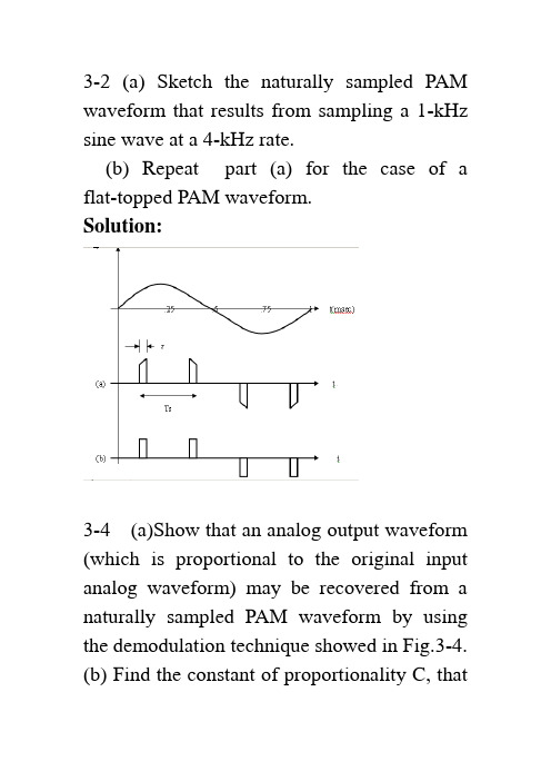
3-2 (a) Sketch the naturally sampled PAM waveform that results from sampling a 1-kHz sine wave at a 4-kHz rate.(b) Repeat part (a) for the case of a flat-topped PAM waveform.Solution:3-4 (a)Show that an analog output waveform (which is proportional to the original input analog waveform) may be recovered from a naturally sampled PAM waveform by using the demodulation technique showed in Fig.3-4.(b) Find the constant of proportionality C, thatis obtained with this demodulation technique , where w(t) is the oriqinal waveform and Cw(t) is the recovered waveform. Note that C is a function of n ,where the oscillator frequency isnfs.Solution:()()()()()()1111sin sin 2cos sin 2cos cos sin [cos 2cos cos sin 2cos s s jk ts k k k jk ts k k s s k s s s s s k n kt kT s t c ek d k d ded d k tk dk dk d w t w t d d k t k d v t w t n tk d w t d n t n d dd k t n tn k ddωωτππωπππωπωππωππωω∞∞-=-∞=-∞∞∞-=-∞=∞=∞=≠-⎡⎤=∏=⎢⎥⎣⎦==+⎡⎤=+⎢⎥⎣⎦==++∑∑∑∑∑∑2]s n t ω211cos cos 222s s n t n tωω=+after LPF:()()()sin sin o w t w t n d d n d n ddn dcw t c ππππ==∴=3-7 In a binary PCM system, if the quantizing noise is not to exceed P ± percent of the peak-to-peak analog level, show that the number of bits in each PCM word needs to be⎪⎭⎫⎝⎛=⎥⎦⎤⎢⎣⎡⎪⎪⎭⎫ ⎝⎛≥P pn 50log 32.350log 10] [log 10102(Hint: Look at Fig. 3-8c.)Solution:Binary PCM M=n2levelsforPPq V P n 100||≤We need)50(log)10(log 50log 5025011002 size step 1022pP n PM P M V P MV nPPPP ≥⎪⎭⎫⎝⎛≥≥=≤≤==δ)(log )(log )(log )(log )(log x b a x x b a b b a ==3-8 The information in an analog voltagewaveform is to be transmitted over a PCM system with a ±0.1% accuracy (full scale). The analog waveform has an absolute bandwidth of 100 Hz and an amplitude range of –10 to +10V .(a) Determine the minimum sampling rate needed.(b) Determine the number of bits needed in each PCM word.(c) Determine the minimum bit rate required in the PCM signal.(d) Determine the minimum absolute channel bandwidth required for transmission of this PCM signal. Solution:(a) Determine the minimum sampling rate needed./sec samples 200)100(22===B f s(b) Determine the number of bits needed in each PCM word.Using the results given in prob. 3-7.(c) Determine the minimum bit rate required in the PCM signal.s f w ords n bits K bits (9)200 1.8 w ord sec sec R ⎛⎫⎛⎫=== ⎪ ⎪⎝⎭⎝⎭(d) Determine the minimum absolute channelbandwidth required for transmission of this920.1%0.1%24250025125009V V V M and n bits a PC M w ord δδδ±=±→====>=→PCM signal.For binary PCM D=RHz9002==⇒D B3-9 An 850-Mbyte hard disk is used to store PCM data. Suppose that a voice-frequency (VF) signal is sampled at 8 ksamples/s and the encoded PCM is to have an average SNR of at least 30dB. How many minutes of VF conversation (i.e., PCM data) can be stored on the hard disk? Solution:53002.6230lg 1022=→=∴=≥=⎪⎭⎫⎝⎛n n M dB MM N S nsec 58sec 40sec 405sec 8kbytes bits byte kbits R kbits sample bits ksamples n f R s =⎪⎭⎫ ⎝⎛⎪⎭⎫ ⎝⎛=⇒=⎪⎪⎭⎫⎝⎛⎪⎭⎫ ⎝⎛==min13,47min 833,2minsec/60sec 10170sec 10170sec10170sec 10510850sec585033336hrs T kbytes Mbytes T ==⨯=⨯=⇒⨯=⨯⨯==3-10 An analog signal with a bandwidth of 4.2 MHz is to be converted into binary PCM and transmitted over a channel, The peak-signal quantizing noise ratio at the receiver output must be at least 55 dB.(a) If we assume that 0=Pe and that there is no ISI, what will be the word length and the number of quantizing steps needed?(b) What will be the equivalent bit rate? (c) What will be the channel null bandwidth required if rectangular pulse shapes are used? Solution:(a) If we assume that 0eP = and that there is no ISI, what will be the word length and the num-ber of quantizing steps needed? Using(3-18),lengthword 9 34.85577.402.6bitsn use n n dB N S peak =⇒≥⇒≥+=⎪⎭⎫⎝⎛steps quantizing 512229===nM(b)sec Mbits6.75Sample bits 9sec 4.8ecMsamples/s4.8)MHz 2.4(22log=⎪⎪⎭⎫ ⎝⎛⎪⎭⎫⎝⎛=====Msamplesn f R f f s anasFor rectangular pulse shapeMHz 6.75==R B null3-12 G iven an audio signal with spectralcomponents in the frequency band 300 to 3000Hz, assume that a sampling rate of 7KHz will be used to generate a PCM signal .Design an appropriate PCM system as follows:a. Draw a block diagram of the PCM system , including the transmitter, channel, receiver.b. S pecify the number of uniform quantization steps needed and the channel null bandwidth required , assume that the peak signal-to-noise ratio at the receiver output needs to be at least 30dB and that polar NRZ signaling is used.c. Discuss how nonuniform quantization canbe used to improve the performance of the system.Solution: (a) 略 (b)lengthword 5 10.43077.402.6bitsn use n n dB N S peak=⇒≥⇒≥+=⎪⎭⎫ ⎝⎛stepsquantizing 32225===nM7sam ples/sec 7 5bits K bits 35 sec Sam ple sec s s f K K sam plesR f n =⎛⎫⎛⎫===⎪⎪⎝⎭⎝⎭()KHzR B null 35==∴( c) uniform quantizing : for all samples,the quantizing noise power is the same 122δ=N↑→↓→NS signal big N S signal smalluniform quantizing is not good for small signal.Nonuniform quantizing: samples are nonlinear processed,Small signal is amplified↑→N S(or small signal ---using small step size ↑→N S )3-14 In a PCM system , the bits error rate dueto channel noise is 10-4. Assume that peak signal-to-noise ratio on the received analog signal needed to be at least 30dB.(a) Find the minimum number of quantizing steps that can be used to encode the analog signal into a PCM signal.(b) If the original analog signal had an absolute bandwidth of 2.7kHz , what is the null bandwidth of PCM signal for the polar NRZ signaling case.Solution: (a) 410-=PedB N S PKout30≥⎪⎭⎫⎝⎛()2231000141PK out S M N M Pe⎛⎫=≥ ⎪+-⎝⎭52206.19===≥n M M use M nKz f s 4.57.22=⨯=27KHz R /274.55===⨯==nullsB sKb nf R 3-17 For a 4 bit PCM system , calculate and sketch a plot of the output SNR(in decibels) as a function of the relative input level , ()20lg rmsx V for(a) A PCM system that uses 10μ= law companding(b) A PCM system that uses uniform quantizationWhich of these system is better to use in practice? Why?Solution: n = 4 bits ---- a PCM word (a)()()()6.02 4.7720lg ln 16.024 4.7720lg ln 11021.25dB SNn dBμ=+-+⎡⎤⎣⎦=⨯+-+⎡⎤⎣⎦=(b)() 6.02 4.7720lg ()6.024 4.7720lg ()28.8520lg ()rm s dBrm s rm s S N n x V x V x V =++=⨯++=+3-19 A multilevel digital communication system sends one of 16 possible levels over the channel every 0.8 ms .(a) What is the number of bits corresponding to each level? (b) What is the baud rate? (c) What is the bit rate? Solution:(a) What is the number of bits corresponding to each level?2164/lL l bits level==⇒=(b) What is the baud rate?311,2500.810secN sym bol D baudT -===⨯(c) What is the bit rate?kbits/sec5)250,1(4===lD R3-20 A multilevel digital communication system is to operate at a data rate of 9,600 bits/s.(a) If 4-bit words are encoded into each level for transmission over the channel, what is the minimum required bandwidth for the channel?(b) Repeat part (a) for the case of 8-bit encoding into each level. Solution:(a) If 4-bit words are encoded into each level for transmission over the channel. What is the min-imum required bandwidth for the channel?(b) Repeat part (a) for the case of 8-bit encoding into each level.600600)1200(2121baud 120089600minHz B HzD B D ===≥==3-24 Consider a random data pattern consisting of binary 1’s and 0’s, where the probability of obtaining either a binary 1 or abinary 0 is21. Calculate the PSD for thefollowing types of signaling formats as a function of b T ,the time needed to send 1 bit of data:(a) Polar RZ signaling where the pulse width isbT 21=τ.(b) Manchester RZ signaling where the pulse width isbT 41=τ. What is the first nullbandwidth of these signals? What is the spectral efficiency for each of these signaling cases? Solution:(a) Polar RZ signaling where the pulse width is bT 21=τ.sin(/2)()[()]2/2b b b T fT F f F f t fT ππ==and the data are independent from bit to bit1:1:210,2n n b a AV AV →+→-,依概率依概率()222:01,221,2nn knFor k A a a a and I A +=⎧⎪⎪===⎨⎪-⎪⎩依概率依概率()2222111(0)()22n n i ii R a a P A A A ===⨯+-⨯=∑The first-null bandwidth is RT B bnull 22==andthe bandwidth efficiency is12R B η==(b) Manchester RZ signaling where the pulse width isbT 41=τ. What is the first nullband-width of these signals? What is the spectral efficiency for each of these signaling cases?()()2,0:3400,0A k Thus R k k ⎧==-⎨≠⎩()()22S s2222222()P ()336T sin (/2)12(/2)sin (/2)4(/2)sj k f T k b b b b b b b F f fR k a T fT A T fT A T fT fT eπππππ∞=-∞=-⎛⎫= ⎪⎝⎭=∑Equation (3-36) can also be used to evaluate the PSD for RZ Manchester signaling where the pulse shape is shown in the figure.⎥⎦⎤⎢⎣⎡-⎪⎪⎭⎫ ⎝⎛=-22)sin()(τωτωτπτπτj j ee f f f F⎪⎭⎫⎝⎛⎪⎪⎭⎫ ⎝⎛=⇒2sin )sin(2)(ωττπτπτf f j f FUsing (3-40) and (3-36), the PSD forManchester signaling is()()2222)][sin(sin 4)(τπτπτπτf f f T A f p b⎥⎦⎤⎢⎣⎡=IfbT 41=τ, this becomes2224sin 44sin 41)(⎥⎦⎤⎢⎣⎡⎪⎭⎫ ⎝⎛⎥⎥⎥⎥⎦⎤⎢⎢⎢⎢⎣⎡⎪⎭⎫⎝⎛⎪⎭⎫ ⎝⎛=b b b b fT fT fT T A f p πππThe first-null bandwidth is RT B bnull 44==and thespectral efficiency is41=η(bits/sec)/Hz.3-29 The data stream 01101000101 appears at the input of a differential encoder. Depending on the initial start-up condition of the encoder, find out two possible differential encoded data streams that can appear at the output. Solution:3-30 Create a practical block diagram for a differential encoding system. Explain how thesystem work by showing the encoding and decoding for the sequence 001111010001. Assume that the reference digit is a binary 1. Show that error propagation can not occur. Solution:3-34 The information in an analog waveform is first encoded into binary PCM and then converted to a multilevel signal for transmission over the channel. The number of multilevels is eight. Assume that the analog signa has a bandwidth of 2700Hz and is tobe reproduced at the receiver output with an accuracy of 1%±(full scall).(a) Determine the minimum bit rate of the PCM signal.(b) Determine the minimum baud rate of the multilevel signal.(c) Determine the minimum absolute channel bandwidth required for transmission of this PCM signal. Solution:1221%50624100V M n V V δδδ±=±→=→==→= m in ()62270032.4/()28332.410.83()5.42s la R nf kb s b L L l R D kBdlD c B kH z==⨯⨯=========3-35 A binary waveform of 9600bits/s is converted into an octal (Multilevel) waveform that is pass through a channel with a raisedcosine-rolloff Nyquist filter characteristic . The channel has a conditioned (equalized) phase response out to 2.4kHz .(a) What is the baud rate of the multilevel signal?(b) What is the rolloff factor of the filtercharacteristic?Solution:09600()8332003()(1)(1) 2.40.52R a L l D Bdl D b B f r r kH z r =→=====+=+=→=3-37 A binary communication system uses polar signal. The overall impulse response is designed to be of thesin x xtype, as given byEq(3-67),so that there will be no ISI. The bitrate is 300/s R f bit s ==.(a) What is the baud rate of the polar signal? (b) Plot the waveform of polar signal at the system output when the input binary data is 01100101. Can you discern the data by looking at this polar waveform? Solution:1502s T f B H z==(b)sin ()s e s f t h t f t ππ=1()eSsf H f f f ⎛⎫= ⎪⎝⎭∏1Ss f DT ==3-43 Using the results of prob.3-42, demonstrate that the following filter characteristics do or do not satisfy Nyquist ’s criterion for eliminating ISI (0022s f f T ==).()()00122eT a H f fT ⎛⎫=⎪⎝⎭∏()()00223eT b H f fT ⎛⎫=⎪⎝⎭∏Solution:()()000012222e T T f a H ffT f ⎛⎫⎛⎫==⎪ ⎪⎝⎭⎝⎭∏∏()()0000232322eT T f b H f fT f ⎛⎫⎪⎛⎫==⎪⎪⎝⎭⎪⎝⎭∏∏3-45 An analog signal is to be converted into a PCM signal that is a binary polar NRZ line code. The signal is transmitted over a channel that is absolutely bandlimited to 4kHz. Assume that the PCM quantizer has 16 steps and that the overall equivalent system transfer function is of the raised cosine-rolloff type with r =0.5.(a) Find the maximum PCM bit rate that can be supported by this system without introducing ISI.(b) Find the maximum bandwidth that canbe permitted for the analog signal . Solution:()0:164 a PC M w ord 40.522 5.33/1T T M n B kH zr B a R D f kb sr==→=====⨯=+量化器()analog analog 2 5.331000667224s b R nf n B R B H zn=≥⋅⨯∴≤==⨯3-47 Multilevel data with an equivalent bit rate of 2,400 bits/s is sent over a channel using a four-level line code that has a rectangular pulse shape at the output of the transmitter. The overall transmission system (i.e., the transmitter, channel, and receiver) has an r =0.5 raised cosine-rolloff Nyquist filtercharacteristic.(a) Find the baud rate of the received signal.(b) Find the 6-dB bandwidth for this transmission system.(c) Find the absolute bandwidth for the system. Solution:(a) Find the baud rate of the received signal.242=⇒==l L l2400/1200aud2D R l B ===(b) Find the 6-dB bandwidth for thistransmission system.611(1200)600H z 22dB B D ===(c) Find the absolute bandwidth for the system.113(1)(10.5)(1200)(1200)900224absolute T B B r D H z==+=+==3-54 One analog waveform w 1(t ) is bandlimited to 3 kHz, and another, w 2(t), is bandlimited to 9 kHz. These two signals are to be sent by TDM over a PAM-type system. (a) Determine the minimum sampling frequency for each signal, and design a TDM commutator and decommutator to accommodate the signals.(b) Draw some typical waveforms for w 1(t ) and w 2(t ), and sketch the corresponding TDM PAM waveform. Solution:(a) Determine the minimum sampling frequency for each signal, and design a TDM commutator and decommutator to accommodate the signals. TDM1122(): 3kH z 6ksam ples/sec (): 9kH z 18ksam ples/secs s t B f t B f ωω=⇒==⇒=(b) Draw some typical waveforms for w 1(t ) and w 2(t ), and sketch the corresponding TDM PAM waveform.3-56 Twenty-three analog signals , each with a bandwidth of 3.4kHz, are sampled at an 8-kHz rate and multiplexed together with a synchronization channel (8kHz)into a TDM PAM signal. This TDM signal is passed through a channel with an overall raised cosine-rolloff Nyquist filter characteristic of r=0.75.(a) Draw a block diagram for the system, indicating the fc of the commutator and the overall pulse rate of the TDM PAM signal.(b) Evaluate the absolute bandwidth required for the channel.Solution:248k pulses/sec=192k pulses/sec D =⨯()()192k pulse/sec110.75168kH z 22D B r =+=+=3-58 Rework Prob.3-56 for a TDM pulse code modulation system in witch an 8-bit quantizer is used to generate the PCM words for each of the analog inputs and an 8-bit synchronization word is used in the synchronization channel.Solution:3-59 Design a TDM PCM system that will accommodate four 300-bit/s (synchronous) digital inputs and one analog input that has a bandwidth of 500Hz. Assume that the analog samples will be encoded into 4-bit PCM word. Draw a block diagram for your design, analogous to Fig.3-39, indicating the data rates at the various points on the diagram. Explain how your design works.Solution:3-60 Design a TDM PCM system that will accommodate two 2400-bit/s synchronous digital inputs and an analog input that has a bandwidth of 2700 Hz. Assume that the analog input is sampled at 1.11111 times the Nyquist rate and converted into 4-bit PCM word. Draw a block diagram for your design, and indicate the data rates at the various points on your diagram. Explain how your TDM scheme works.Solution:。
基于等效采样原理的数字示波器
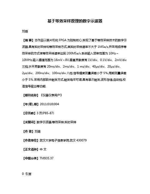
基于等效采样原理的数字示波器刘璐【摘要】本作品以单片机和FPGA为控制核心,实现了基于等效采样技术的数字示波器.具有实时采样和等效采样方式,其实时采样速率不大于1MSa/s,并采用顺序等效采样的方式使等效采样速率达到200MSa/s.系统输入频率范围为10Hz~10MHz,输入幅值范围为16mV~8V,垂直灵敏度有1V/div、0.1V/div、2mV/div 三档,水平灵敏度有20ms/div、2ms/div、1 ms/div、40μs/div、20μs/div、2μs/div、200ns/div、100ns/div八档.信号幅度测量误差小于5%,周期测量误差小于5%.采用内部软件触发方式,触发电平可调.具有单次触发,波形存储,自动档,校准信号输出等功能.【期刊名称】《仪器仪表用户》【年(卷),期】2011(018)004【总页数】3页(P85-87)【关键词】数字示波器;等效采样;实时采样【作者】刘璐【作者单位】武汉大学电子信息学院,武汉430079【正文语种】中文【中图分类】TM935.370 引言在数字示波器技术中,常用的采样方法有两种[1]:实时采样和等效采样。
实时采样是指在触发信号到来后,一次性完成整个数据采集过程,其特点是顺序,等时间隔,通常对信号的实时采样都必须满足Nyquist采样定理[2],采样频率至少为待采样信号频率的2倍。
然而,在数字示波器应用中,通过对信号采样,在时域内完成波形的重绘,一个周期内仅采集信号的两个点是远远不够的。
为了准确恢复时域上的波形,一个完整的周期至少有10个以上的采样点,即采样频率至少为待采样信号的10倍。
对高频信号进行实时采样,必然要求更高速的A/D采样芯片,同时高速转换会使转换精度下降,系统成本上升。
为了解决对高频周期信号的数据采集,发展出了等效采样技术[3]。
等效采样(Equivalent Sampling)是指对多个信号周期连续样来复现一个信号波形,采样系统能以扩展的方式复现频率大大超过奈奎斯特极限频率的信号波形。
Mitra《数字信号处理-基于计算机的方法》翻译 武汉大学 孙洪ch7 adaptive
Time constant:
1 − 2 µλk = e
Average time constant:
1 −τ
= 1−
1 1 1 + −L ≈ 1 − τ 2!τ 2 τ
v′ 1 − 2µλmin )v′ min (n + 1) = ( min ( n) λmax λmin
τk =
1 2 µλ k
τ av =
Performance criterion
e (n )
Optimum solution
W = Wopt
武汉大学 研究生课程 © 2002 孙洪 1 武汉大学 研究生课程 © 2002 孙洪 2
Basic elements of a general adaptive filter
x(n )
Input signal
The deepest-descend method
The deepest-descend method
Gradient of the MSE function
E e 2 (n) = rdd (0) − 2W T (n)rxd (n) + W T (n) Rxx (n)W ( n)
The gradient of the MSE function: The steepestdescent method:
The stochastic difference equation – weight-error
= (I − 2µR )E [W ( n)] + 2µRWopt
Convergence condition: the same as the deepestdescend method
E [W (n + 1)] = E [W ( n) + 2µX (n)e(n)]
- 1、下载文档前请自行甄别文档内容的完整性,平台不提供额外的编辑、内容补充、找答案等附加服务。
- 2、"仅部分预览"的文档,不可在线预览部分如存在完整性等问题,可反馈申请退款(可完整预览的文档不适用该条件!)。
- 3、如文档侵犯您的权益,请联系客服反馈,我们会尽快为您处理(人工客服工作时间:9:00-18:30)。
Filtering
A/D conversion Frequency selective filters Filter banks Lattice filter realizations
l
Signal analyses
– To extract useful information – Spectral estimation, signal modeling – Classification, detection, prediction, representation
Model-based Signal Processing (2) ModelSignal
Random signal (nonlinear model)
Model-based Model(parametric) Method
l
1 Introduction
Analyses
Higher-order spectrum Self-similar model Chaotic model
Viener filter Kalman filter Optimum filters Parametric Random signal spectral (probability estimation model) (stationary linear model) (time-variant linear model)
武汉大学 电子信息学院 研究生课程 © 2002 孙洪 9
Adaptive filter Time-frequency /scale analysis Wavelet
© 2002 孙洪 10
more and more unpredictable
武汉大学 电子信息学院
研究生课程
1 Introduction
研究生课程
1 Introduction
1 Introduction
Implementation of filters
l l
Applications of DSP
l
Basic structures
– direct form, cascade form, … By techniques
– – – – – – – –
l
Combination / complecation of systems
– Iteration – Forward and back ward
Classification Detection Prediction Compression Noise cancelation Equalization Deconvolution Restoration
武汉大学 电子信息学院 研究生课程 © 2002 孙洪 12
武汉大学 电子信息学院
现代数字信号处理
2
1 Introduction
1 Introduction
Blind Signal Processing
Signal
Random signal
Blind Method
Filtering
l
Analyses
Filtering
Higher-order spectral filter Homomorphic Fractional spaced equalizer
(probability modeliener Filtering Model (HMM)
研究生课程 © 2002 孙洪 11
Signals
– Be a function of independent variables – Carries information
Signal
Deterministic (equations) (mono-rate) (local linear technique)
Analyses
DFT Decomposition
其它专著
6
武汉大学 电子信息学院
研究生课程
© 2002 孙洪
5
武汉大学 电子信息学院
研究生课程
© 2002 孙洪
现代数字信号处理
1
1 Introduction
l
1 Introduction Waveform-based Digital WaveformSignal Analysis and Processing
l
l
姚天任,孙洪:《现代数字信号处 理》,华中理工大学出版社,1999 V.K.Ingle and S.M. Kogon,:Statistical and Adaptive Signal Processing, McGraw-Hill, 2000 S.V.Vaseghi: Advanced Digital Signal Processing and Noise Reduction, Second Edition, John Wileys’ Sons. LTD., 2000
l
Prerequisites
– Basic digital signal processing – Probability theory – Linear algebra
Introduction (signal analysis and filtering) Fundamentals of Discrete-Time Signal Processing Random Signals and Probability Models Optimum Linear Filters Adaptive Filters Linear Signal Models and Prediction Spectral Estimation Some Further Topics
Decomposition of random (unknown model) signal in probability space . . .
Neural network Particular filtering . . .
Both advantages of waveform-based methods and model-based methods Both drawbacks waveform-based methods and model-based methods.
Time/scale analysis Modern digital signal analysis
Beyesian statistical processing
© 2002 孙洪
Nonlinear (blind) filtering
16
武汉大学 电子信息学院
研究生课程
© 2002 孙洪
15
武汉大学 电子信息学院
l
Signal filtering
– To improve the quality of a signal – Digital filters, optimum ~, adaptive ~, array ~ – Cancelation, equalization, deconvolution, …
Multirate sampling
17
l
By areas
– – – – – – – Speech / audio Image / video Communication Radar / sonar Biomedical signal Geophysics Seismic data
Decomposition of systems
– Polyphase (multirate) realization – Minimum-phase and all-pass – Complementary systems
研究生课程 © 2002 孙洪 4
武汉大学 电子信息学院
研究生课程
© 2002 孙洪
武汉大学 电子信息学院
Preface
Preface
Theory and Practice
l l l l
Bibliography
l
Computer experiments using MATLAB functions Seminar Term Paper Examination
7
武汉大学 电子信息学院
研究生课程
© 2002 孙洪
武汉大学 电子信息学院
研究生课程
© 2002 孙洪
8
Waveform-based Waveform(non-parametric) Method (nonl
1 Introduction
1 Introduction
Model-based Signal Processing (1) ModelSignal Analyses Filtering
现代数字信号处理
孙洪
Preface
l
The principal objectives
– A unified theory – Implementation – Applications Of modern signal processing methods.
Modern Digital Signal Processing
Advantage: normally outperform nonparametric methods, since they utilise more information in the form of a model of the signal process. l Drawback: they can be sensitive to the deviations of a signal from the class of signals characterised by the model.