电动抽液泵使用说明书
电动抽油泵说明

电动抽油泵说明电动抽油泵概述:SB抽油泵是我公司引进西德优质样机开发研制而成,各项技术指标均能达到样机水平,并在样机基础上开发了不同的使用场合不同抽吸液体的系列派生产品,该系列泵为轻便型管式轴流泵,具有效率高,使用、维修方便等特点。
SB型油泵广泛用于化工、石油化工、精细化工、染料化工、环保、水处理、医药、食品等部门抽吸不同液体。
如在易燃易爆场合使用,可选用我公司生产的防爆型电动抽液泵。
(SB-3型、SB-4型)使用油泵时应按CB38361-2《爆炸环境用防爆电气设备》有关规定并正确使用防爆插头插座。
抽油泵可以直接插入物料桶(最大适用于符合GB/325-1991标准的钢桶)中抽取桶中液体。
可输送各种油料、带腐蚀性化学药水、其他液体。
根据所输送的液体性质,电动抽油泵泵体沾湿部分材料可选用铝合金、不锈钢,316不锈钢等组成。
驱动电机配备单相标准电机,防爆电机,高转速电机等多种选择。
根据材质,电机不同,型号可分为:SB-1,SB-2,SB-3,SB-3-1,SB-4,SB-5,SB-6,SB-7,SB-8系列铝合金,不锈钢或防爆型。
我们备有详细资料,欢迎索取。
该系列泵可按防爆区域和非防爆区域选用,凡在防爆区域使用配置防爆型电机,这类电机分三种机组型号,当使用条件含各种易燃易爆混合时,应选用最高组级。
该系列泵可输送酸、碱、盐、油品、饮料等介质,广泛用于化工、石油化工、精细化工、染料化工、环保、水处理、医药、食品等部门。
同时适用于中小型油田、油库、炼油厂、加油站、农机站、企事业单位、车队、车辆船舶等输送汽油、煤油、柴油、轻质燃油的理想工具 .电动抽油泵性能参数:产品型号流量流量扬程转速功率进口出口材质重量m3/h L/min m r/min Kw mm mm泵管KgSB-17.81307.510000 1.15025不锈钢8 SB-1-1 6.61107100000.885025不锈钢7.5 SB-1-27.81307.510000 1.15025不锈钢8 SB-1-3 6.61107.5100000.885025不锈钢7.8 SB-27.81307.510000 1.15025铝合金 5.5 SB-2-1 6.61107.5100000.885025铝合金 5.3 SB-3915010120000.885025不锈钢9 SB-3-1915010120000.885025不锈钢9.5 SB-4915010120000.885025铝合金7.5 SB-66100780000.554125不锈钢 5.7 SB-76100780000.554125不锈钢 5.5SB-86100780000.554125铝合金 3.8电动抽油泵使用与维护1、全新或长期搁置不用的电动抽油泵使用与维护,开箱后用500伏兆欧表测量所有带电零件与可能触及的金属零件之间绝缘电阻,在接近工作温度时应不低于7兆欧。
电动抽水机使用方法说明书

电动抽水机使用方法说明书使用方法说明书尊敬的用户,感谢您购买我们的电动抽水机。
为了您能够顺利使用该产品并达到最佳的使用效果,我们特别提供了以下使用方法的说明,请您仔细阅读。
一、产品概述1.1 产品简介电动抽水机是一种便携式的水泵设备,能够快速抽水并将水流送至需要的地方。
该产品可以广泛应用于家庭、农田灌溉、建筑工地等多个领域。
1.2 主要特点- 便携式设计,方便携带和使用;- 高效抽水,提供稳定的水流;- 高效过滤系统,有效过滤杂质;- 低噪音设计,使用过程安静舒适。
二、使用准备2.1 确认配件完整性在使用之前,请确保配件完整。
包括电动抽水机主体、电源线、水管连接器等。
2.2 检查外观和功能请仔细检查电动抽水机外观是否完好,并确保各个功能开关正常。
2.3 水源和电源准备选择一个合适的水源,并确保电源电压符合要求。
三、使用步骤3.1 连接水源和出水管道将水源与电动抽水机的进水口连接,确保连接牢固;然后将出水管道与电动抽水机的出水口连接。
3.2 开启电源将电源线插入电源插座,并按下电源开关,此时电动抽水机即开始工作。
3.3 调节水流根据需要,您可以通过调节电动抽水机上的水流调节阀来控制水流大小。
3.4 结束使用当使用完成后,先关闭电源开关,然后拔掉电源线。
四、使用注意事项4.1 安全使用在使用电动抽水机时,请确保周围环境清洁、干燥,避免进水口接触到腐蚀性液体。
4.2 防止过热长时间连续使用电动抽水机可能会导致过热。
为了防止过热,建议您每次使用后休息一段时间。
4.3 防止堵塞为了保持电动抽水机的正常工作,建议定期清洗水泵和过滤器,避免堵塞。
4.4 保养与维修定期检查电动抽水机的各个部件,如有损坏或故障,请及时寻求专业维修人员的帮助。
五、常见问题解答接下来,我们列举了一些常见问题及解答,希望能够帮助您更好地使用电动抽水机。
问题1:电动抽水机没有水流出。
解答:请检查水源是否正常、水泵是否连接正常、电源是否打开等。
电动油泵说明书

一、产品型号、名称二、技术性能ZB4-500D型电动油泵技术性能三、构造简介本油泵为高压电动油泵,由泵体、组合控制阀、车体管路、液压控制回路等五部分组成。
1、泵体该泵系采用自吸式轴向柱塞泵。
电动油泵带动轴旋转,轴在旋转过程中,通过设置于该轴上的推力轴承逐次将柱塞压入油缸,而吸油弹簧靠其弹力时刻使柱塞贴紧在推力轴承端盖上,轴和弹簧的交替作用使柱塞在油缸中往复运动,在进、排两单向球阀同步配合下,便在出油嘴得到连续均匀的出油。
该泵共有6个油缸,圆周等分排列又交错分成两条排油路,每一排油路均由三个相间120°角的油缸组成。
两条排油路单独出油,各不相扰。
本泵头系阀式配流,斜盘式轴向柱塞泵,设有5XΦ10柱塞副,公称流量为2L/min,最高压力为50MPa。
泵头结构示意图如图1。
图1 泵头构造示意图2、控制阀整组控制阀是在原ZB4-500型电动油泵控制阀基础上增加比例溢流阀PMVP4-44/24及球式电磁换向阀VZP1D22-G24而成。
工作时把与P 口(在阀块上打有钢印)连接的原ZB4-500电动油泵一侧控制阀关闭,另一侧控制阀开启,系统的压力由比例溢流阀调定,压力的高低变化与控制电流的变化有关。
千斤顶的伸缩缸通过电磁换向阀的切换来实现。
3、控制回路4、油箱小车车体采用薄板焊接结构,油在下部,主泵直接浸入油中。
泵、阀和电动油泵与翻板系固定联接,高压管采用Φ9x2.5紫铜管及Φ6高压胶管,低压管采用Φ11x0.5透明塑料管和Φ6高压胶管。
油箱采用钢板焊接,容量约为42L。
小车安装固定轮及万向轮,转向灵活,运输轻便。
5、电器开关采用磁力开关,以减少负载时的启动电流。
四、使用与保养(一)灌油本油泵采用优质矿物油,油内不含水、酸及其他杂质混合物,粘度约为2~3,根据环境温度实际情况一般可采用液压油L-HM32(冬用)或L-HM46(夏用)灌油前需经过滤,并应把油箱、泵体管路等处清洗干净,否则泥沙铁屑等脏物带入将可能发生不正常的磨损和刮伤,甚至造成事故。
QDX、QD、QY、WQ潜水电泵使用说明书

QDX、QX、QD、QY型潜水电泵Type QDX、QX、QD、QY Submersible Pumps安装使用说明书Instruction On Installation And Operation湖南湘电长泵(长沙水泵厂)长一制泵有限公司ChangYi Pump Manufacturing Co.,Ltd. Of XiangDian Chang Sha Pump Works一、概述本系列水泵由电机、泵体、机械密封(动密封、静密封)等部件组成,采用优质材料精制而成。
具有结构科学、小巧轻便、用途广泛等特点,是先进的排灌设备。
警告1、每台电泵都有接地标志,电泵必须可靠接地,并在供电线路中装漏电保护器。
2、严禁用力拉扯电缆(电源线),以免电缆线断裂而造成漏电。
3、电泵泵体潮湿时,在通电的情况下请勿触摸。
泵使用中,工作面附近水域内,禁止洗涤、游泳或放牲畜下水,谨防意外发生。
4、因维修或清理等,需移动电泵时,应先行切断电源。
5、安装使用前,请详阅说明书。
电泵泵体上贴有警告标志,为了您和他人的安全,请保持此标志完整清晰,不要随意撕落、涂沫或涂改。
另外,因产品不断开发,本公司保留技术更改权。
未列入本说明书内的产品,其技术参数请参见铭牌数据,在下一版本说明书中将作出调整。
感谢您选购本公司产品,务请依照说明书,正确操作与使用。
二、系列潜水电泵安装使用及注意事项1、潜水电泵必须按实际需要在推荐的扬程范围内选用,以防过载运行而损坏电机。
选用电泵扬程应考虑管路及弯头损失,一般每10米水平管道损失1米扬程,每一弯头损失1米扬程。
2、使用前,先检查电缆线及插头是否完好无损,各处螺栓有无松动,有无油浸出泵壳。
电机相线间及接地线与相线间绝缘电阻值应大于50兆欧,还必须安装漏电断路器等保安设施。
每台电泵都附有接地标记,应进行可靠接地。
3、在河塘安装电泵时,最好垂直放置在竹篓或其他网篮内,以防水草等杂物进入、堵塞叶轮。
可用三角架或借助船、桥、码头等吊放。
3电动抽液泵安全操作规程
电动抽液泵安全操作规程
1使用范围
1.1电动抽液泵可用来抽水和润滑油。
1.2不准用电动抽液泵抽吸汽油、易燃清洗剂等易燃易爆液体。
2使用前的检查
2.1使用前检查确认电缆线无破损,电缆线有破损的电动抽液泵不准使用。
2.2使用前要检查确认电源电压在合适的范围内(220伏—230伏)。
2.3检查确认定期检验标志清晰、未超期。
2.4检查泵的出入口管路无堵塞后接好出入口管路。
2.5合闸前确认电动抽液泵开关在关位。
2.6点动电动抽液泵检查确认其运行平稳、无异音。
3使用方法和操作程序
3.1在启动开关按下后,检查泵排放口是否有液体排出,如无液体排出要查明原因,
不可让泵长时间空转。
3.2使用过程中如泵体振动变大或声音异常要立即停泵,查明原因经处理后方可投
入使用。
4维护和保养
4.1在进行检查排除故障前一定要将电源断开。
4.2电动抽液泵由班组设专人保管,使用后将泵体及管路清理干净,储存于干燥处。
4.3每六个月由电气试验人员进行试验,外壳绝缘不良的不准使用。
5注意事项
5.1必须使用带漏电保护器的电源。
5.2因故离开工作场所或暂停工作以及遇有临时停电时,须立即切断电源。
5.3高处使用时要做好防止高空坠落的安全措施。
5.4电动抽液泵的电线不准接触热体,不要放在湿地上,并避免载重车辆和重物压
在电线上。
机务维护部
2004年12月16日。
YBYB型手提式电动油桶泵使用说明

【YBYB型手提式电动油桶泵】使用说明:1 电动机的使用,详见YBYB6312隔爆型油桶电泵电容运转异步电动机产品使用维护说明书》。
2 油桶泵使用前应接通电源并扭转电机开关,检查电泵运转是否正常,叶轮旋转方向是否正确。
3 油桶泵应轻轻插入和抽出油桶,避免泵体与油桶出油口边之间激烈磨擦。
·4 转动电机开关待泵启动后,应检查流量和扬程是否正常,并检查电机运转和温升等情况。
5 抽完一桶油后应马上停机,如电泵较长时间不工作时应将电流断开。
油桶泵切忌干运转。
怎样选择水泵?建议从五个方面加以考虑,既液体输送量、扬程、液体性质、管路布置以及操作运转条件等。
1、流量是选泵的重要性能数据之一,它直接关系到整个装置的的生产能力和输送能力。
如设计工艺能算出泵正常、最小、最大三种流量。
选择泵时,以最大流量为依据,兼顾正常流量,在没有最大流量时,通常可取正常流量的1.1倍作为最大流量。
2、扬程是选泵的又一重要性能数据,一般要用放大5%—10%余量后扬程来选型。
3、液体性质,包括液体介质名称,物理性质,化学性质和其它性质,物理性质有温度c、密度d、粘度u,介质中固体颗粒直径和气体的含量等,这涉及到系统的扬程,有效气蚀余量计算和合适泵的类型:化学性质,主要指液体介质的化学腐蚀性和毒性,是选用泵材料和选用那一种轴封型式的重要依据。
4、管路布置条件指的是送液高度送液距离送液走向,吸如侧最低液面,排出侧最高液面等一些数据和管道规格及其长度、材料、管件规格、数量等,以便进行系梳扬程计算和汽蚀余量的校核。
5、操作条件的内容很多,如液体的操作T饱和蒸汽力P、吸入侧压力PS(绝对)、排出侧容器压力PZ、海拔高度、环境温度操作是间隙的还是连续的、泵的位置是固定的还是可移的。
选购方法水泵的流量,即出水量,一般不宜选得过大,否则会增加购买水泵的费用。
应按需选用,如用户家庭使用的自吸式水泵,流量应尽量选小一些的;如用户灌溉用的潜水泵,就可适当选择流量大一些的。
BQS型水泵说明书(煤矿用)
YBQW— □ / 2 ( ) 电压,单位:伏(V) 电动机级数 电动机额定功率,单位:千瓦(kW) 矿用隔爆型潜污水电泵用电机
2
目录
一、 概述 …………………………………………………………………………………3
二、 产品结构特征及工作原理……………………………………………………………5
三、 技术特性 …………………………………………………………………………….5
四、 泵的选型及安装调试 ………………………………………………………………8
式, 立式、 干式电动机,电压:660/1140
4
(3).BQW 型 矿用隔爆型潜污水电泵型号: B Q W □—□—□ / □
电泵叶轮形式特征 K—开式 电动机额定功率,单位为千瓦(kW) 电泵额定扬程,单位为米(m) 电泵额定流量,单位为立方米每小时(m3/h) 电泵输送介质:W—污水 潜水电泵 矿用隔爆型
41.7
80
9
40 70 22
660/1140
39.3
80
9
80 60 30
45.05
100
9
80 80
37
100 60 37
110 50 45
50 150 45
44.2
80
9
47
80
9
380/660
51
100
9
40.2
100
9
360 28
53.4
KRT 40至700废水用潜水电动泵说明书
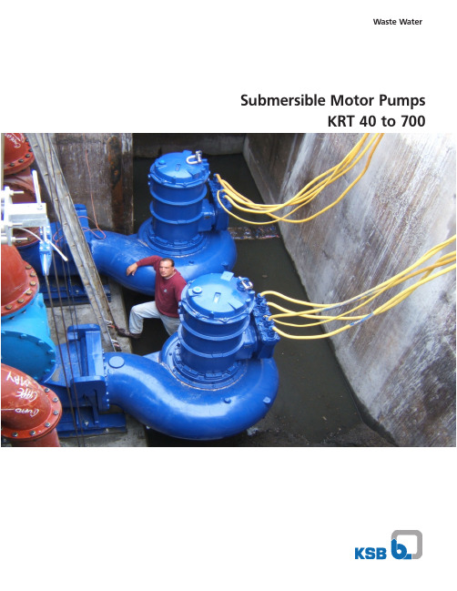
Waste Water Submersible Motor PumpsKRT 40 to 700Three (3) 161 hp Dry-Pit Pumps with cooling jacketKRT Submersible motor pumps for Versatile ApplicationsAdvantages and technical features:• economical installation• wet installation submersible motor pumps operate submerged in the pump sump• low building costs, eliminating intermediate shaft, drainage pump and superstructure• pump stations below ground do not spoil the landscape, traffic areas remain unchanged when sumps are located under roads • the compact pump/motor sets require less space and are easier to install• with the double pump guides the pump can be installed at any installation depth and withdrawn without difficulties • no need to enter the pump sump to carry out inspection and maintenance work• smaller inspection opening on duplex pump sets• small pump sump due to high permissible switching frequency • stationary and portable applications possible, see types of installations• permanent dry well installation possible where the pump is exposed to the danger of occasional flooding • minimum assembly and maintenance work• no coupling to be aligned since KRT pump and motor have a common shaft• no sealing or flushing water required or leakage outlet • motor cooled by the medium• high operation safety (dry running possible)• quiet operationKRT submersible motor pumps are highly efficient in the handling of:- raw sewage containing solid and long fibrous mixtures - contaminated liquids with a high gas and air content - liquids containing sludge and solid substances - concentrated sludge (KRT with agitator) for circulating and mixing the medium prior to pumping - floating sludge and debris such as vegetable wastes, wood chips and similar waste (KRT as a vacuum suction pump on a pontoon)- dirty water and storm water - raw and activated sludge - flume and wash water - pulp- slaughter house wastes - water/product suspensions - sand/cement/water mixtures - plastic granules in liquid - textile effluent- industrial effluent and wash water as well as media in production plants, e.g. flume water, scale wastes, cutting oil and other media containing abrasive components.- chemical and waste disposal effluent with pH-values 2 to 12- effluent containing acid- seawater and brackish water as well as other media with chlorine.Type of construction:KRT submersible motor pumps are submerged, single stage close-coupled pump sets. Depending on the liquid to be pumped and the size of the pump different impel -ler shapes are used: K - Closed non-clogging 2 or 3 vane impeller E - Single vane impeller F - Vortex impellerS - Cutting or Grinding impellerD - Open single vane impellerFields of application:Two (2) 148 hp Submersible Pumps with cooling jacket.1 - Reliable Motor - specifically designed for submersible pumps with air filled housings, explosion proof ratings, continuous duty cycles and automatic monitoring of winding temperature and moisture.2 - Water Tight Cable Entry - power cables with grommet and washer. Cable entry further epoxy sealed to insure no liquid gets inside the motor even if the cables are severed below water level.3 - Non-proprietary silicon carbide faced mechanical seals mounted in tandem in an oil bath.4 - Pump and motor shafts of stainless steel or Gr 1045 carbon steel protected and isolated by stainless steel shaft sleeves.5 - Flexible Hydraulic System - enclosed 1, 2 and 3 vane, recessed, grinder or open single vane impellers available to allow a hydraulic selection ideally suited for a particular application.6 - Major castings of ASTM A 48 Class 35 B cast iron, duplex stainless steel and wear resistant chromium white iron to Brinell 1000 available.7 - Automatic discharge connections with a positive seal between pump and elbow insures zero leakage.8 - Hard metal wear rings maintain hydraulic efficiency.The Safe and Reliable SolutionMotors smaller than ~80 hp :Motors 5 hp and below :9 - Major castings of ASTM A 48 Class 40 B cast iron, duplex stainless steel and wear resistant chromium white iron to Brinell 1000 available.10 - Plug in cable entry for a simple, polarized connection, fast pump installation and removal.11 - All-in-one bearing, seal, and gasket kits that areinterchangeable for all pump sizes, reducing spare parts costs.• 12 •• 3• 4• 5• 7• 910 •• 1• 4• 5• 6• 7• 3• 82 •The right impeller design for cost effective and reliable operationSince no one type of impeller is equally suitable for all applica -tions, KSB offers the KRT series of submersible motor pump with various types of impellers according to specific requirements. Our range of vortex, single vane and non-clogging impellers allows thebest impeller to be selected for the product with due consideration of operating parameters such as flow rate, head, efficiency, solidsize, wear behavior and gas content.Flexible installationsStationary guide wire installationStationary guide rail installationTransportable installationDryinstallationStationary guide wire or guide rail installation - for installation in the pump sump with suspension device ensuring automatic pres -sure-tight coupling of the pump.Transportable installation - with base stand and flange connection for pipework or hose connection (e.g. with rigid coupling)Dry installation - for installation in a separate dry well.The Pump That Keeps Cool1 - Cable Entry - absolutely water tight even in the event of damage to the cable sheath and core insulation there is no possibility of mositure entering the motor chamber along the strands due to capillary action.2 - Thermal Motor Protection - extensive sensor technology for permanent monitoring to ensure trouble-free operation.3 - High Efficiency Motor - all motors FM approved for Class I, Division 1 Group C & D hazardous locations.4 - OPTIONAL Closed-loop Cooling System - optimal cooling in all operating conditions with no external cooling required, perfect for dry-well installations .5 - Non- proprietary silicon carbide faced mechanical seals mounted in tandem in an oil bath.6 - Major Casting of ASTM A 48 Class 35 B Cast iron, Duplex Stainless steel and wear resistant Chromium White Iron.7 - Heat exchanger and separate coolant circulating impeller for optional cooling jacket.8 - Enclosed 1, 2 and 3 vane or recessed impellers available to allow a hydraulic selection ideally suited for a particular application.9 - Wear rings in hard metal to insure continued high efficiences and long impeller life.10 - Pump and motor shafts of stainless steel or Gr 1045 carbon steel protected and isolated by stainless steel shaft sleeves.11 - Temperature monitoring available for lower bearing12 - Float sensor in separate leakage collection chamber. Prevents leakage from reaching motor or lower bearing.* Motors larger than ~80 hp:• 1• 2• 3• 4• 6• 8• 910 •11 •12 •• 5• 7* For certain models, 30, 40, 50, 56, and 74 HP motors with cooling jacket are also available.06Installations and Technical DataThree (3) 12“ discharge, 161 hp closed-loop cooling dry-pit pumps with stainless steel Jacket in existing pumping station.Dry Well InstallationsTwo (2) large 24“ discharge, 148 hp Submersible Pumps with stainless steel cooling jacket on KSB guide rail system for an effluent waste water treatment pumping station.Wet Well Installations Three (3) 10“ discharge, 194 hp closed-loop cooling dry-pit pumps with stainless steel Jacket in existing pumping station.Two (2) large 24“ discharge, 251 hp Submersible Pumps and one (1) 12“ discharge, 80 hp on KSB guide cable system for a stormwater station.Technical DataOperating Data Pump Size - DN 2” - 30”Capacity - Q (gpm)up to 45,000Head - H (ft)up to 330Liquid Temperature - t (°F)up to 140Motor Rating - P (hp)up to 1,080Material Options Cast Iron A 48 Class 35 B Wear Resistant Chromium White IronA 532 II C 15% CrMo-HcDuplex Stainless Steel A 743 CD 4 MCU Part Designation GG1G2GHHC1C2Pump Casing A 48 Class 35 BA532 II C 15% CrMo-Hc A 743 CD 4 MCU Intermediate Casing A 48 Class 35 BA 532 II C 15% CrMo-HcA 743 CD 4 MCU Shaft A 276 Type 420;A 576 Gr. 1045 w/shaft protection sleeve A 276 S 31803/A 576 Gr. 1045ImpellerA 48 class 35B A 743 CD 4 MCU A 532 IIC 15% CrMo-HcA 276 S 31803/A 576 Gr. 1045Motor Casing A 48 Class 35 BA 743 CD 4 MCU Discharge Elbow A 48 Class 35 BA 532 II C 15% CrMo-HcA 743 CD 4 MCUPower/Control CableNeopreneKSB, Inc.4415 Sarellen Road Henrico, VA 2553.031/2-14 / 02.10 © K S B I n c 2008Your local KSB representative:S u b j e c t t o t e c h n i c a l m o d i f i c a t i o n w i t h o u t p r i o r n o t i c e。
QW型泵说明书
QW型潜水电泵使用说明书QW型潜水电泵使用与维护说明一、使用条件1、最大介质温度40℃;2、PH值4-10;3、可通过最大固体颗粒直径Φ70-Φ125㎜;4、比重原则上不超过1.1;5、每小时启动次数不多于6次,且间隙时间均匀;6、泵体上的进水孔及过滤后的较清洁海水(海水中的悬浮物直径小于5㎜)。
二、产品系统说明QW系列产品由电机与泵两部分组成,二者通过油隔离室及机械密封组件隔开。
整个水泵长度智短,结构紧凑,并设置了各种保护装置,使得泵运行安全、可靠。
三、吊运和使用注意事项1、吊运时,用带钩的链条钩在吊环上,注意保护电缆不受损伤。
2、水泵不能放在污水的入口处。
当水泵座处在泥地上或浮砂上,水泵由于震动,产生下陷,在这种情况下,建议将水泵放在一个较大的底板上。
3、如果泵在运转而气温降至0℃以下时,可以继续使用。
4、出水管内径应符合规定的要求。
5、在污水中使用的泵,如机壳周围堆积了泥浆、杂物等。
这样降低了传热的速度,使电动机内部的温度上升,缩短定子的使用寿命或赞成无缘故的跳闸,所以在污水液位抽吸至最低之后,用软管定期冲洗泵,外壳、清除杂物。
必要时,拆开冷却套端固定板,清理冷却套及循环水管中杂物层。
6、注意,未切断电源前,不得移动或提升水泵。
四、使用说明在安装和使用水泵之前,必须详细阅读说明书,避免使用不当而损坏机器,仔细检查一下,水泵的选型是否正确,实际使用条件是否与规定的使用条件一致。
水泵启动前:应由一名合格的电工,对该系统进行检查,确保采取下述各项所要求的电器保护措施。
1、泵在运转前,应用0~500V兆欧表检查电机主电缆三相绕组对地绝缘电阻,最低不得小于1兆欧,绝不允许用摇表检查控制电缆,避免损坏内部电子元件。
2、电源电压一定要在铭牌上标出的额定电压±5%的范围内,电源电压升高值不允许超过额定电压的10%,如果电源离水泵使用的地方距离较远时,电缆的截面积应加粗,接头尽可能少些,且接头处必须作密封处理,以防漏水。
使用说明书(QDX、QY、WQ、WZB、JET、G)

使⽤说明书(QDX、QY、WQ、WZB、JET、G)使⽤说明书安装、使⽤产品前,请阅读使⽤说明书●QDX、QX型下泵式⼩型潜⽔电泵●QY型充油式⼩型潜⽔电泵●WQ、WQD型污⽔污物潜⽔电泵●WZB型旋涡式⾃吸电泵●JET型喷射泵●G型管道泵浙江新⽻机电有限公司前⾔本说明书依据GB9969.1-1998《⼯业产品使⽤说明书总则》及GB/T9480-2001《农林拖拉机和机械、草坪和园艺动⼒机械使⽤说明书编写规则》的要求编写。
本说明书详细阐述了本企业系列产品的使⽤和说明,为⽤户在正确选⽤、安装、使⽤和维护保养本企业系列电泵提供帮助,⽤户在安装、使⽤本企业系列电泵产品前,请详阅使⽤说明书。
出版:浙江新⽻机电有限公司地址:温岭市泽国镇天皇村邮编:317523电话:0576-********编号:OYJ.463开本:16K版次:2007年6⽉第1版印次:2007年6⽉第1次印刷感谢你选购本企业⽣产的系列电泵,我们恳请您在安装、使⽤前仔细阅读本说明书,并遵循其建议,严格按要求安装使⽤、维护保养。
为了您和他⼈安全,使⽤前必须可靠接地,并加装漏电保护器。
贴于泵体中间的警⽰标志,要保持清洁,不得随意撕落、涂改;若警⽰标志丢失或不清楚,请与供应商联系,及时更换警⽰标志并重新贴于泵体中间。
1、请严格按《使⽤说明书》使⽤;2、通电前,请仔细检查绝缘电阻,以防漏电;3、电泵应可靠接地,并在使⽤前安装漏电保护装置;4、严禁⽆⽔试机、脱⽔运转或超负荷运转,严禁提拉电缆,应系绳吊放;5、电泵运转时,⼿和⼈体不可触摸或靠近被输送液体及电泵,⼯作⽔⾯附近不得洗涤、游泳和放牲畜下⽔,应做好隔离⼯作;6、维修或清理电泵前,应切断电源。
⽬录⼀、电泵安装使⽤及注意事项 (1)1、潜⽔电泵 (1)2、微型电泵 (2)⼆、电泵⽤途及技术规格 (3)1、QDX、QX型下泵式⼩型潜⽔电泵 (3)2、QY型充油式⼩型潜⽔电泵 (5)3、WQ、WQD型污⽔污物潜⽔电泵 (7)4、WZB型旋涡式⾃吸电泵 (9)5、JET型喷射泵 (11)6、G型管道泵 (12)三、故障原因及排除⽅法 (14)四、售后服务指南 (15)五、售后服务信息反馈 (16)六、保修卡 (16)⼀、电泵安装使⽤及注意事项1、潜⽔电泵使⽤前,先检查电缆线及插头是否完好⽆损,各处螺栓有⽆松动,有⽆油渗出泵壳。
海尔湿灌洗水槽电动泵用户手册说明书
-1-HIDRO-HML SERIES PUMPWHIRLPOOL BATH PUMPUSER MANUALWhen installing and using this electrical equipment, basic safety precautions should always be followed, including the following:1.READ AND FOLLOW ALL INSTRUCTIONS2.WARNING To reduce the risk of injury . Do not permit children to use this product unless they are closely supervised at all times.3.WARNING Risk of Electrical Shock . Connected only to grounding type receptacle protected by a ground fault circuit interrupter (GFCI). Contact a qualified electrician if you cannot verify that the receptacle is protected by GFCI.4.CAUTION Do not bury cord . Locate cord to minimize abuse from lawnmowers, hedge trimmers, and other equipment.5.CAUTION In case the running parts will injure people, don't make the electric pump running before then pipeline have been connected.6.WARNING To reduce the risk of electrical shock, replace damaged cord immediately.7.WARNING To reduce the risk of electrical shock, do not use extension cord to connect unit electric supply; provide a properly located outlet.8.CAUTION This pump is for used for fix-installed bath tub, It is not suitable for swimming pool spa.9.Do not install within an outer enclosure or beneath the skirt of a hot tub unless so marked.10.This appliance is not intended for use by young children or infirm persons unless they have been adequately supervised by a responsible person to ensure that they can use the appliance safely.11.Young children should be supervised to ensure that they do not play with the appliance.12.FOR INDOOR USE ONLY .13.SA VE THESE INSTRUCTIONS.IMPORTANT SAFETY INSTRUCTIONS-2- This product 1.GENERAL_ These instructions are for correct installation,and optimum performanceof the bath pumps, so they should be read carefully._ These are single - stage centrifugal pumps designed to operate withcompact hydromassage equipment, They are equipped with a totalemptying system to prevent the discharge of residual liquid in eachstopping._ _ These units are designed to operate with clean water at a maximum water O temperature of 50C._ O O Storage temperature: -10C ~ +50C. Relative A ir Humidity:95% Max._ Built of top quality materials, they are subjected to strict hydraulic and electrical controls and are carefully verified._Correct installation is ensured by following these instructions and those of the wiring diagram; otherwise, over loads may be produced in the motor. We decline responsibility for any damage caused by not following these instructions.2.I NSTALLATION_Dimensions and position of the pumpfor supporting and fixing the pump within this space(Pig.2)._ Pump must be fixed by screw on the tub shelf, and fixed with silent block to lower the noise and libration. Sticking and enlacing is forbidden._ The pump will be getting hot in operating , to speed up cooling, the minimum distance between the motor of the pump and the surrounding structure should not be less then 20mm._ The suction, pipe of the pump should be as short as possible._ The rating Label must be visible after installation._ Parts containing live parts, except parts supplied with safety extra low voltage<12V, must be inaccessible to a person in the bath._ Class I appliances must be permanently connected to fixed wiring. Part including electrical components except remote control devices must be located or fixed so that they cannot into bath.most not be disposed together with the do mestic waste. of electrical and electro -nic appliances.By collecting and recycling waste,you help save natural resources, and make sure the product is disposed in an environmental friendlyand healthy way.This product has to be disposed at an authorized place for recycling V/Hz esp: See pump nameplate.-3-3.PIPE ASSEMBLY_ The maximum inlet water pressure 0.15MPa._ The suction pipes should have a diameter equal to or larger than of the discharge pipes. It can avoid the loss of the head and improve the efficiency._ The suction and discharge pipes should not rest above the pump in any case._ Seal all the connectors and unions well. Avoid any dripping on the motor,which would unfailingly damage it._ Should be use the new hose module which supplements along with the bathtub, the old hose module cannot be reused.4.ELECTRICAL CONNECTION_ The electrical install action should have a multiple separation system withcontacts opening at least 3mm._ For continued protection against possible electric shock this unit is to be mounted to the base in accordance with the installation instructions.1) The protection of the system should be based on a residual current device (RCD) with a rated tripping current not exceeding 30mA. The supply cable should comply with EMC standards. 2) Single-phase motors have built-in thermal protection._ The electric connection must be carried out by qualified staff following strictly the "EN60335-2-60" standard._ Be sure that the earth cable connection is correctly made._ Wires serving as equipotential bonding conductors shall have a cross22 sectional area between 2.5 mm and 6 mm and shall be equipped with the terminal suitable receptacle.5.CONTROLS PRIOR TO INITIAL START-UP_ Verify that the pump shaft turns freely._ Check that the mains voltage and frequency are according to the nameplate._ The hydromassage assembly should be equipped with a system to prevent the pump from starting up if a minimum water level is not present. _ Check the rotating direction of the motor, which should concur with that indicated on the fan cover._ If the motor does not start up, try to locate the problem in the table of most common faults and their possible solutions that is provided further on._ THE PUMP SHOULD NEVER OPERA TE DRY .-4-6.START-UP_ Start electrically the pump only when the suction and discharge pipes are connected to the corresponding inlets and outlets._ Apply voltage to the motor and suitably adjust the jets to obtain the desired flow.7.MAINTENANCE AND CLEAN_ Our pumps for hydromassage facilities do not require any special maintenance or programming. If the pump will be idle for a long period of time , it is recommended to disassemble , clean and store it in a dry , well ventilated place. If the supply cord is damaged, it must be replaced by the manufacturer or its service agent or a similarly qualified person to a hazard.8.TROUBLE SHOOTING GUIDELOW VOL TAGE SYMPTOMPOSSIBLE CAUSECHECKPUMP DOES NO TURNNO POWER TO PUMP-Incoming power to the pump?-Is circuit breaker on?-Is GFCI operating properly?-Is the air switch plugged in?AIR SWITCH DISCONNECTED -Is the air switch hose connected to thepump?-Is the air switch hose connected to theactuator button on the tub deck?-Jets should be pointed away from the suction inlet so air is not forced into pump suction.-Is the in tub suction inlet blockedor covered?-Is there any debris in the pump housing?-Is there a leak in the piping or the pump?BLOCKAGE ORLEAKPUMPNOT PUMPING PROPERLY -Is the proper voltage applied to thepump?-Is there an extension cord being used?-5-9.INSTALLATION DIAGRAMFig.1Fig.2HIDRO-HML200(H) 1.50 2.0 380 Power(P)1ModelkW HP HIDRO-HML300(H) 2.20 3.0395L HIDRO-HML250(H)1.852.5 380 HIDRO-HML1501.101.5 380-6-P e r f o r m a n c e c u r v e sF l o wH e a d (m )E d i t i o n : 2017-06 a。
3A6850H电动泵产品说明书
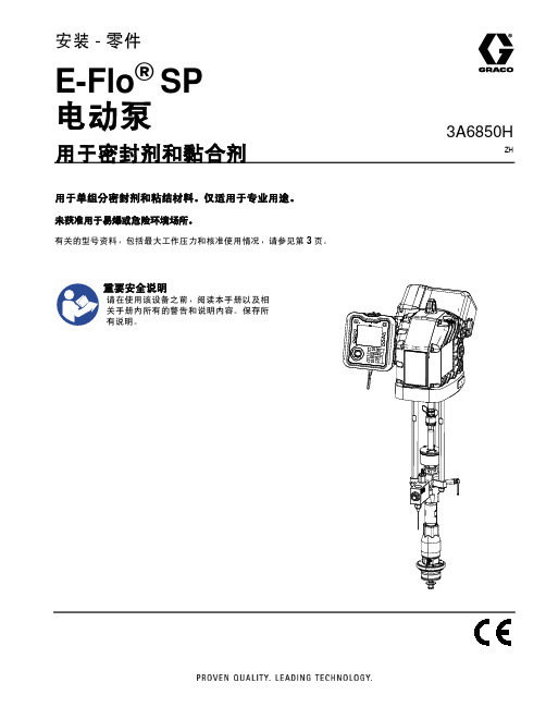
3A6850HZH安装 - 零件E-Flo ®SP 电动泵用于密封剂和黏合剂用于单组分密封剂和粘结材料。
仅适用于专业用途。
未获准用于易爆或危险环境场所。
有关的型号资料,包括最大工作压力和核准使用情况,请参见第 3 页。
重要安全说明请在使用该设备之前,阅读本手册以及相关手册内所有的警告和说明内容。
保存所有说明。
相关手册23A6850H目录相关手册 . . . . . . . . . . . . . . . . . . . . . . . . . . . . . . . . . . 2型号 . . . . . . . . . . . . . . . . . . . . . . . . . . . . . . . . . . . . . . 3系统压力 . . . . . . . . . . . . . . . . . . . . . . . . . . . . . . . 4警告 . . . . . . . . . . . . . . . . . . . . . . . . . . . . . . . . . . . . . . 5部件辨认 . . . . . . . . . . . . . . . . . . . . . . . . . . . . . . . . . . 7带 100 cc Check-Mate CS 下缸体的电动泵 . . . . 7高级显示模块 (ADM) . . . . . . . . . . . . . . . . . . . . . . 8安装 . . . . . . . . . . . . . . . . . . . . . . . . . . . . . . . . . . . . . . 9定位和安装 . . . . . . . . . . . . . . . . . . . . . . . . . . . . . 9接地 . . . . . . . . . . . . . . . . . . . . . . . . . . . . . . . . . . . 9电源要求 . . . . . . . . . . . . . . . . . . . . . . . . . . . . . . . 9连接电源 . . . . . . . . . . . . . . . . . . . . . . . . . . . . . . 10连接独立变压器 . . . . . . . . . . . . . . . . . . . . . . . . . 11在设备使用之前安装开口机油盖 . . . . . . . . . . . . 12流体软管的连接 . . . . . . . . . . . . . . . . . . . . . . . . . 12连接多个泵 . . . . . . . . . . . . . . . . . . . . . . . . . . . . 13设置 . . . . . . . . . . . . . . . . . . . . . . . . . . . . . . . . . . . . . 14湿杯 . . . . . . . . . . . . . . . . . . . . . . . . . . . . . . . . . . 14冲洗泵 . . . . . . . . . . . . . . . . . . . . . . . . . . . . . . . . 14泄压步骤 . . . . . . . . . . . . . . . . . . . . . . . . . . . . . . . . . 16关闭并维护泵 . . . . . . . . . . . . . . . . . . . . . . . . . . . . . . 16驱动器维护 . . . . . . . . . . . . . . . . . . . . . . . . . . . . . . . . 17零配件 . . . . . . . . . . . . . . . . . . . . . . . . . . . . . . . . . . .18带 Check-Mate 下缸体的电动泵 . . . . . . . . . . . .18带 Dura-Flo 下缸体的电动泵 . . . . . . . . . . . . . . .22单向阀 . . . . . . . . . . . . . . . . . . . . . . . . . . . . . . . .25套件及附件 . . . . . . . . . . . . . . . . . . . . . . . . . . . . . . . .28高级显示模块配件包 25E439 . . . . . . . . . . . . . .28通信网关模块 (CGM) 配件包 . . . . . . . . . . . . . . .29入口压力传感器配件包,24Y245 . . . . . . . . . . .30泵架式机架,253692 . . . . . . . . . . . . . . . . . . . .31壁式安装支架,255143 . . . . . . . . . . . . . . . . . .31地板安装适配器,223952 . . . . . . . . . . . . . . . . .32CAN 电缆 . . . . . . . . . . . . . . . . . . . . . . . . . . . . . .32灯塔配件包,255468 . . . . . . . . . . . . . . . . . . . .32I/O 电缆,122029 . . . . . . . . . . . . . . . . . . . . . . .32尺寸 . . . . . . . . . . . . . . . . . . . . . . . . . . . . . . . . . . . . .33E-Flo SP 泵尺寸 . . . . . . . . . . . . . . . . . . . . . . . .33泵机架安装孔图表 . . . . . . . . . . . . . . . . . . . . . . .34地板支脚安装孔图表 . . . . . . . . . . . . . . . . . . . . .35电动驱动器安装孔位置图 . . . . . . . . . . . . . . . . . .35变压器安装孔图表 . . . . . . . . . . . . . . . . . . . . . . .36泵性能 . . . . . . . . . . . . . . . . . . . . . . . . . . . . . . . . . . .37E-Flo SP 性能图表 . . . . . . . . . . . . . . . . . . . . . . .38技术规格 . . . . . . . . . . . . . . . . . . . . . . . . . . . . . . . . . .43美国加州第 65 号提案 . . . . . . . . . . . . . . . . . . . . . . .44Graco 标准保修 . . . . . . . . . . . . . . . . . . . . . . . . . . . .46相关手册这些手册可以从 网站获取。
SB型电动抽液泵电动油桶泵使用说明及价格

【SB型电动抽液泵┃电动油桶泵】使用说明:1、使用规定电压:线路电压不超过抽液泵铭牌上所规定电压的±10%方可使用。
2、如何装备:开箱后按结构示意图装配,接上电动机(1)并紧接连手机(2)使之泵体与电机为一体(3)上接好出水轮管3、使用前检查各部件外型完好才能开机使用。
4、本抽液泵不宜作空运转,使用时,抽吸完毕,即停泵,否则会加速叶轮密封件轴承等磨损。
也可能磨损泵管,因本泵电机空载转速可达10000转/分。
5、及时调换电刷,电刷磨损到将不能使用时,须及时调换(2只电刷同时调换)否则会使电刷与换向器接触不良引起环损,损坏换向器,严惩时会烧坏电枢。
6、在下列情况下不得使用,在使用过程中如发现绝缘损坏,电源线工电缆护套破裂,插头插座开裂或接触不良,以及断续运转,出现严惩火花等故障时,电机外壳操作时,应立即进行修理。
在未修复前不得使用。
7、防止过载,使用时,凡遇转速异常或降低时,应即停机检查是否有杂物卡住叶轮或电机是否发生故障,抽液泵因故刹车时必须立即切断电源。
8、使用工具要爱惜,所有抽液泵要小心轻放避免受到冲击。
SB型电动油桶泵价格流量流量扬程功率进口出口价格型号m3/h L/min m Kw mm mm 元304不锈钢防爆SB-3-1 9 150 10 0.88 50 25 1350 铝合金防爆SB-4 9 150 10 0.88 50 25 750普通不锈钢SB-6 6 100 7 0.55 41 25 825普通铝合金SB-7 6 100 7 0.55 41 25 525小型油泵价格品名型号不含税运价格含税运价格电压功率流量扬程柴油\煤油泵价格G12ZYB 150 180 直流12V 150w 40l/min 10m柴油\煤油泵价格G24ZYB 156 187 直流24V 150w 40l/min 10m柴油\煤油泵价格G12ZYB(正反转)168 202 直流12V 150w 40l/min 10m柴油\煤油泵价格G24ZYB(正反转)179 215 直流24V 150w 40l/min 10m大功率不锈钢柴油\煤DYB70型950 1140 直流12V/24V 370瓦 70L/min 16米油泵价格大功率柴油\煤油泵价DY70型325 390 直流12V/24V 500瓦 70L/min 10米格两相防爆油泵价格DY-80型300 360 交流220V 50Hz 550W 80L/min 10m两相防爆不锈钢油泵价DYB-80型525 630 交流220V 51Hz 550W 80L/min 15米格柴油、煤油泵价格DY-90型325 390 交流220V 50Hz 750W 90L/min 10米220V防爆总成1065 127812Vor24V直流总成580 69612Vor24V直流防爆总成1065 1278。
Rexroth PGZ 泵使用说明书
德国rexroth泵PGZ使用说明力士乐致力于为各类机械和系统设备提供安全、精准、高效以及高性价比的传动与控制技术。
公司融合全球的应用经验,研发创新的产品,为行走机械、机械应用与工程、工厂自动化及可再生能源每一个细分市场的客户量身定制系统解决方案及服务。
博世力士乐同时为客户提供各种液压、电子传动与控制、气动、齿轮、线性传动及组装技术。
公司业务遍及全球80多个国家,拥有37,500多名专业员工,2012年全球的销售额近65亿欧元。
业务部门行走机械:建筑机械、物料搬运设备、农业与林业机械、商用/公路汽车机械应用与工程、工厂自动化:运动机构、汽车工业、采矿业、石油和天然气钻探(地面)、舞台技术、化工业、印刷与纸张处理、能源技术、物料输送、玻璃机械制造、橡胶加工、半导体和电子工业、木工行业、水平定向钻机、发动机、塑料机械和拉磨机、冶金、矿山设备、组装与装卸、挖泥船、近海工程、加工与包装、测试技术、回收和垃圾处理、船舶工程、运动模拟技术、太阳能、机床(切削)、水利工程、盾构机、金属成形机床和压机、传送技术、流体动力研究、船厂设备、水泥工业、制糖工业、纸浆和造纸机械。
可再生能源:风能产品组群驱动技术、电子传动与控制技术、浇注成型技术、齿轮技术、工业液压、线性传动技术、行走液压、组装技术、气动、拧紧与焊接技术Gerotor泵具有恒定排量PGZ帧大小4,5尺寸20 (140)最大工作压力15bar最大排量136.3cm?特征具有固定排量的低压泵极低的运行噪音适用于广泛的粘度和速度范围出色的吸力特性可与轴向柱塞泵,内齿轮泵和叶片泵组合使用用途:工业或移动应用中的低压冷却,过滤器或润滑剂回路,例如塑料加工机器,机床,压力机和风力涡轮机。
一般技术数据产品描述建立PGZ型液压泵是具有恒定排量的齿轮泵。
它们基本上包括:法兰壳体(1),轴(2),置换器元件内转子(3)和齿轮转子(4)以及驱动盘(5)和盖(6)。
吸气和置换程序通过驱动盘,轴沿指示的旋转方向驱动内转子。
日立液相L-2130泵中文使用说明书3

三、功能3.1 仪器键盘3.1.1 每一部分的名称和功能主开关排气阀左门右门LED排水池漏液传感器图3-1 前视图●主开关:开关电源●门:有两个门●排气阀:打开可以清洗系统●漏液传感器:检测液体的泄漏●UI-键盘:可独立操作泵的键盘(可供选择)●LED :共有4个指示灯,每个灯都有特定的颜色对于不同的检测指示配线盖板I/F板安装空间接地线配线盖板泵能用外部信号启动泵能用外部信号停止压力值被输出到外部(约49Mpa)/lv图3-2 后视图配线盖板:配线盖板:打开左侧盖板(见前视图),可以看到用于L-2000系列之间的e-line连接器,这些配线盖板也可以用作固定板,使L-2000仪器和仪器之间紧固一些。
地线端:有三个端子可供仪器接地使用。
I/F板安装空间:既安装I/F的空间,该板是用来连接计算机(数据库)和高效液相系统。
表3-1 后面板上每个端子的名称和功能3.1.2 UI 键盘的名称和功能(选项)(1) 操作键以下是UI 键盘操作面板的每一个键的作用解释。
(2) 监控屏幕UI 键盘提供了一个液晶显示的监控屏幕,它可以指示仪器的运行状态,指示仪器状态的屏幕叫做监控屏幕,监控屏幕的操作方法和指示的例子如下所示。
(a) 第一监控屏幕主要指示泵的主结构信息当两种液体在进行低压梯度操作时,%C 和%D 总是0。
泵的状态指示在监控屏幕的右上方,如下所示。
[GR]该梯度程序在执行中[I N] 等待分析的执行,A 液已被输送。
[ -- ] 等待分析的执行,泵已停止。
[MN] 手动程序被选择。
[PG] 清洗程序在执行中。
[LK] 操作盘的键盘被锁定。
(b)第二监控屏幕(c)第三监控屏幕(d)监控屏幕的转换监控屏幕按下面方式转换,如果连接程序功能是OFF,那么第四监控屏幕将不显示。
1)第一监控屏幕2)第二监控屏幕3)第三监空屏幕4)第四监控屏幕3.2 操作状态表示被压下的键)<打开电源>MANUAL :操作在不使用程序的条件下进行。
电子水泵系统说明说明书

LNNote,a system may take 24 hours to vent all the air in the system to atmosphere.ATTENTION DO NOT run the pump dry as this will result in bearing failure.Speed RegulatorOutput of the CP range of domestic circulators is by 3 speed control.(Single speed versions are also available)Speed regulator adjustment should only be made with electrical supply switched off.1.It is always preferable to use the lowest performance where this gives circulationsufficient to heat all the heat emitters evenly (uneven distribution of heat may be due to the need to balance the flow of water in each heat emitter).2.If the pump performance requirement is not known start with the lowest pumpsetting.If heat emitters remain cold,or if the boiler inlet and outlet temperature differential (specified by the manufacturers of the boiler) is not achieved increase the flow by adjusting the speed control as shown in fig.7.ATTENTION too high a speed setting may result in pumping over or drawing in air.Important - DO NOT use pump isolating valves for performance control.6.MaintenanceNo routine maintenance is necessary,however,during prolonged shutdown e.g.summer months,it is advisable to run the pump for a few minutes every few weeks.Locked PumpShould the pump fail to start,switch to maximum setting.If the pump still does not start,the manual restart knob can be used to free a locked pump (see manual restart procedure - section 5).Once the pump is running the regulator should be reset to its original position.7.Trouble Shooting GuideFaults and Remedies Pump Fails to Start Check power supply fuses.Check voltage at pump terminals (see pump nameplate data).Check electrical connection wiring procedure (see section 4.3).Check rotor free to rotate (see section 6).Pump Starts but Provides Incorrect Circulation Check pump valves open.Check pump case and system adequately vented (see section 5).Check correct electrical regulator setting (see section 5).NoiseCheck electrical regulator setting and readjust as required (see section 5).Noise due to cavitation can be subdued by increasing the system pressure within the permissible limits.Pump may require 48 hours to attain normal quiet operation.8.Relevant DocumentationSpare PartsNo non-approved replacement parts may be used.Publication CPUK 10/02.Printed in the U.K.PART NO.6479433 (230V)In accordance with our policy of continual product improvement,we reserve theright to amend the specification of these products without prior notice.COMPACTDOMESTICCIRCULA TOR PUMPInstallation and Operating InstructionsCirculating Pumps Ltd,Oldmedow Road,Kings Lynn,EnglandT echnical Helplines (01553) 7648214.3 Electrical Connections ATTENTIONElectrical work to be carried out by competent qualified and licensed electricians in strict conformity to ruling national conditions and local regulations.All wiring and external switchgear to comply with the ruling local regulations in accordance with the latest edition of IEE wiring regulations.Observe pump name plate data.For pump fuse protection use a 3 Amp fuse.A means of disconnection from the power supply having a contact separation of at least 3mm in all poles must be provided.If the pump already has a cable fitted to it,ensure the pump is isolated from the mains before removing the terminal cover.Wiring Proceduree heat resisting 3 x 0.75mm 2 core cable with rubber insulation rated at110ºC minimum.2.Cut cable to required length.3.Remove terminal cover.4.Thread cable through grommet.5.Depress levers to open cable clamps.Connect cable - Brown to L,Blue to N,Y ellow/Green to see Fig 6.6.See Fig 6.7.Refit terminal cover,locating cover onto motor and tighten screws.The cable must not come in contact with the pump body or pipework.W ARNING - ‘THIS PUMP MUST BE EARTHED’missioning/Operation ATTENTIONOpen both valves either side of the pump.In normal operation the pump surface can be hot (up to 125ºC) creating a risk of being burnt.Manual Restart (First Commissioning)During this operation be aware of the risk of scalding from escaping hot water or steam.Before switching the pump on the manual restart Fig 7 should be unscrewed and withdrawn to engage in the motor shaft.Check that the shaft rotates freely ,and that the knob can be seen rotating on initial start up of the circulator.Screw manual restart back in.(CP23/CP43/CP53/CP63 only).V entingWhen the system is filled with water the pump will normally self vent air within a short while of switching on.In cases where the pump venting is slow (identified by pump noise) the pump bearings may be quickly vented by using the manual restart knob.During this operation ensure the pump is switched off.Once the system has filled,switch off the pump,unscrew the manual restart knob applying sideways pressure to the screw until water emerges from it.Screw the manual restart knob back in.Switch pump back on.Fig 6 Plan view of T erminal Arrangement1.General Safety RulesThese instructions are of fundamental importance for the installation,use andmaintenance of these products and must therefore be read before commencing work and then carried out accurately by the installer and end user.Installation and maintenance must be carried out by qualified personnel only .Failure to comply with these safety instructions will cause risk to people and equipment and may invalidate the guarantee.Danger from general causes:Instructions which if ignored could cause damage or impair the function of the pump are highlighted by the word:ATTENTION1.1 Field of ApplicationThe CP range is suitable for open vented or pressurised domestic central heating systems only.1.2 Product DataW eight CP21/23/41/43/51/53 2.8Kg (6.3lbs)W eight CP61/632.9Kg (6.5lbs)Maximum water temperature 110ºC (230ºF)Maximum Ambient temperature 55ºC Maximum static pressure 10 bar(147p.s.i.)(102m water gauge)Max system pressure =Max head m wg from Fig 1 to Fig 4 + Max static pressure 102mwg Minimum recommended flow rate5 l/minOperating conditions - When pumping water at 110ºC the minimumdynamic head should be 11 meters water gauge to avoid cavitation and ensure quiet running.Minimum static head - open vented systems CP pumps may be fitted tosystems with a minimum static head of 300mm provided the pump inlet is adjacent to the neutral point and the water temperature does not exceed 80o C.Fig 1 CP21/23 Performance Curve - 230V ~ 50HzW ater T emperature - 20ºC.For CP21 use speed 3.Fig 2 CP41/43 Performance Curve - 230V ~ 50HzW ater T emperature - 20ºC.For CP41 use speed 3.Fig 3 CP51/53 Performance Curve - 230V ~ 50HzW ater T emperature - 20ºC.For CP51 use speed 3.Fig 4 CP61/63 Performance Curve - 230V ~ 50HzW ater T emperature - 20ºC.For CP61 use speed 3.Supply voltage 230V ~ 50Hz Model Speed Speed W atts Amps SettingRPM Input CP212600600.28CP411950710.30CP5118501040.45CP6118001100.48CP2332600600.2822450450.2012100350.16 CP4331950710.3021550550.2411150400.18CP53318501040.4521400780.351950560.26CP63318001100.4821400830.3711050600.27Dimensions2.Packaging & Handling2.1 Transport and Storage ATTENTIONThe pump must be protected from moisture,and must not be subjected to temperatures outside -10ºC and 50ºC.2.2 Handling ATTENTIONCare must be taken when handling and installing the pump to avoid damaging components.If damage occurs the pump must not be used.Abnormal handling may invalidate the warranty.3.Description of Pump3.1 General DescriptionThe pumps are of a drum motor design using hard coated shaft and bearings supporting a moulded impeller and rotor.Motor cooling and bearing lubrication is carried out by the pumped water.Models offer a single or variable speed setting to allow system requirements to be accurately met.Design and Function/Safety DevicesThe motor windings are impedance protected.A provision for earthing the outer casing is provided.Prohibited Use ATTENTIONThe pump must not be used on secondary hot water services or handling drinking water or handling food related liquids.4.Installation4.1 Electrical Connection Block PositioningIf the electrical connection block is not in a convenient position when the circulator is delivered,the motor head may be rotated prior to fitting.Release the screws on the pump casing and rotate the motor head to its new position.If this is done please check the following :-1.Take care not to remove or damage the ‘O’ring seal between motor headand pump casing.2.Tighten the fixing screws in a diagonal pattern in stages to a final torque of25Kg cm (22lb in).3.Check the motor is still moving freely by loosening the Manual RestartKnob (fig.7) and then withdrawing until it engages in the motor shaft.The motor should then be free to turn with the finger tips.N.B.After use the Manual Restart Knob should be screwed back finger tight into its original position.4.2 System ATTENTIONThe pump must not be installed against wood or any other material which may be effected by heat from the pump.Before installing the circulator ensure all soldering/welding adjacent to the pump is complete,the system has been thoroughly flushed out to remove any foreign matter and that vent and feed pipes are positioned so that the pump will not draw in air or pump over.It is advisable to ensure the impeller is free by rotating manually through the outlet.The pump should not be installed in either a high point in the system where air could collect or a low point where sediment could build up.Pipes on both sides of the pump should be supported to reduce strain and must be correctly aligned prior to installing the pump to reduce the risk of scalding.The pump must be installed with the rotating shaft horizontal (see fig.5)Fig 5 Pump Installation PositionsCheck the direction of flow indicated by an arrow on the pump casing and install the pump between the isolating valves.When replacing a pump maintain the same direction of flow.Use approved makes of additives with corrosion inhibitors only and follow manufacturer’s instructions.Do not leave system empty without protection from corrosion inhibitor.Ensure no fluid drips onto the pump motor or its electrical connections during installation,venting or operation as when the pump is energised this may create a risk of electric shock.76.78046.6105.4130/1801”/1.5”/2”BSP 1200123456712345Q(m /h)H (m )PC1394CP21132112345672345Q(m /h)H (m )PC1393123CP4100123456712345Q(m 3/h)H (m )PC1392123CP510.0012345670.51.01.52.0 2.53.03.54.04.5Q(m /h)H (m )PC1372123CP6112.0 S L O T。
电动给水泵使用说明书

100SB-P锅炉给水泵安装使用说明书100SB-P-SM郑州电力机械厂2009年7月1用途及型号1.1用途1OOSB 一P 型锅炉给水泵是50 ~1OOMW火力发电机组配套的电动全容量定速锅炉给水泵。
给水的最高温度为160 ℃,也可作为油田注水用水泵。
1.2 性能范围流量:230 ~440 t/h(可根据需要选择)扬程:1460 ~1600m (可根据需要选择)进口压力:0.59MPa效率76 %~81 % (效率与流量有关,额定流量大时效率较高)转速:2980 r/min1.3配用电机型号:根据水泵轴功率选定、2 结构说明1OOSB -P 型给水泵是单壳体、分段、多级离心泵。
2.1定子部分定子部分主要由吸入、吐出端轴承部件、吸入段、吸入吐出水封体、吐出段、导叶、中段等组成,用穿杠连接,成为一个刚性整体结构,安装在泵座上。
为保持美观和隔热,泵体上用泵罩覆盖,泵罩用螺栓固定在泵座上。
吸入段的进口和吐出段的出口均垂直向上。
泵的吸入段、中段、吐出段的端面密封采用金属面直接密封(硬密封), 并辅以绕垫加强密封效果,在拆装给水泵时,必须对其密封面加以仔细保护。
在泵座与泵体之间安装有横向键和纵向键,可保证水泵受热后横向对称膨胀及在轴线方向上能向吐出端自由膨胀。
2.2转子部分水泵转子由吸入吐出段轴封套、首级叶轮、次级叶轮、调整套、平衡盘、前后轴压套、推力盘、推力盘轴向调整套等组成,由轴套螺母和推力盘锁紧螺母固定在轴上。
叶轮和轴之间为过盈量很小的过盈配合,这种结构能增加转子的刚性,减少泵运行时的振动,装拆时应将叶轮加热到180℃左右(但不宜超过200℃),使叶轮内孔膨胀后再拆装。
加热叶轮应从叶轮后盖板最大外圆处开始,逐步向中心靠近,最后加热到叶轮尾部。
叶轮经精加工后作静平衡,最大外圆处残余不平衡重量不大于2 克。
转子部件组装后,作动平衡试验,平衡精度为G2.5级,残余不平衡量不大于120 克〃厘米2.3平衡机构平衡机构由平衡盘、平衡套及推力轴承组成,用以平衡轴向推力。
抽水泵的操作规程

抽水泵的操作规程一、目的本文档旨在规范抽水泵的操作流程,确保安全高效地使用抽水泵,保护设备和人员安全。
二、适用范围本操作规程适用于各类抽水泵的操作使用。
三、操作准备1.确保操作人员已经接受过相关的培训,并具备操作抽水泵的资格。
2.检查抽水泵设备的完好性,包括电线、插头、开关等是否有损坏。
3.检查抽水泵设备的周围环境,确保没有堆积物、阻塞物或其他障碍物。
4.熟悉抽水泵设备的显示界面和操作按钮的功能和用途。
四、操作流程1.接通电源:–插好插头,确保电源线可靠连接。
–打开抽水泵设备的电源开关。
2.设置操作参数:–根据实际需要,设置抽水泵设备的相关参数,如流量、压力等。
–遵循设备的操作手册或相关指导,进行参数设置。
3.启动抽水泵:–按下设备的启动按钮,等待抽水泵启动。
–观察设备显示界面,确保设备正常运行。
4.监测操作:–操作抽水泵期间,要定期观察设备的运行状态和指标,如温度、电流等。
–如发现异常情况,应立即停止抽水泵,并进行故障排除。
5.使用结束:–当抽水任务完成后,将抽水泵设备关闭。
–先按下设备的停止按钮,等待设备停止运行。
–再关闭设备的电源开关,拔掉插头,断开电源。
6.设备清洁:–在使用完抽水泵设备后,应及时清洁设备,清除泵体和管路中的积水、污物等。
–检查设备的过滤网和进出水口,清理其中的杂物。
五、注意事项1.操作人员应经常检查抽水泵设备的运行状态,如果发现异常情况,应及时停止设备并寻找故障原因。
2.操作人员应遵循设备的操作手册,不得擅自调整设备参数或进行维修操作。
3.操作人员应定期对抽水泵设备进行保养,如更换损坏的零部件、清洗润滑等。
4.在操作过程中,应严格遵守相关安全规定,穿戴好必要的安全防护装备。
5.使用抽水泵设备过程中,要注意节约资源,避免浪费。
6.如发生紧急情况或意外事故,操作人员应立即停止设备并及时报告上级。
六、附件无以上,即为抽水泵的操作规程。
在操作抽水泵之前,操作人员应严格遵守本规程,依次进行操作准备、操作流程以及注意事项,确保抽水泵设备的正常运行和人员的安全。
E2-30、 40电动泵指导手册

指导手册指导手册E2E2--30 30 电动泵电动泵电动泵• 107071型 (欧盟型号)• 107074 型(美国型号) • 107075型 (日本型号)E2E2--40 0 电动泵电动泵电动泵• 107093 型(欧盟型号)• 107094型 (美国型号) • 107095型 (日本型号)Note: Read and follow all instructions and safety precautions before using this equipmentProduct Description107071 – E2-30 Electric Pump107093 – E2-40 Electric PumpThis equipment is designed for use with Solvent based and Waterborne materials. Suitable for use in Zone 1 and 2, Protection Level: II 2 G XManufacturer: - Finishing BrandsJustus-von-Liebig-Straße31,63128 Dietzenbach. DEEU Declaration of ConformityWe: Finishing Brands declare that the above product conforms with the Provisions of Machinery Directive 98/37/EC, the Provisions of Pressure Equipment Directive 97/23/EC and the ATEX Directive 94/9/EC by complying with the following statutory documents and harmonized standards: -Machinery Safety Standards BS EN ISO 12100 Part 1 and 2Pressure Equipment Regulations 1999 (SI 1999/2001)Explosion Prevention Potentially Explosive Atmospheres BS EN 1127-1Non-electrical Equipment for Potentially Explosive Atmospheres BS EN 13463-1 2001 Constructional Safety for Potentially Explosive Atmospheres BS EN 13463-5 2003 Providing all conditions of safe use stated within the product manuals have been complied with and that the final equipment into which this product is installed has been re-assessed as required, in accordance with essential health and safety requirements of the above standards, directives and statutory instruments and also installed in accordance with any applicable local codes of practice.PM Green (General Manager)4th April 2007引索 引节章 节1.1 概述 (4)1.2 工作原理..........................5-6 1.3 规格. (7)1.4 尺寸与安装详图 (8)2.1 重要安全信息························9-113.1 安装--概述 (11)3.2 安装-电气/接地·······················12-133.3 安装--机械 (14)4.1 操作····························14-155.1 零件清单--主泵组件·····················16-17 5.2 零件清单--机械传动组件···················18-215.3 零件清单--流体部分组件···················22-236.1 维护--组装程序.......................24-32 6.2 维护--概述.........................33-34 6.3 维护-电机/齿轮箱. (35)6.4 维护--故障查找 (36)6.5 维护--测试/润滑/排放 (37)7.1 备件清单 (38)8.1 附件 (39)概述-1.1E2-30、40电动泵泵使用标准的防爆变频交流异步4极电机驱动流体部分,以输送油漆、溶剂及其它适当的材料。
BRW400/31.5乳化液泵使用说明

Ah1x泵站操作人员必须经过专业培训后方可上岗。
2、严格按照《使用说明书》要求进行操作。
3、使用前应检查各联接部位及高压密封部位,确保联接可靠、密封安全。
3、严禁液压系统在泄漏状态下工作,对泄漏物要及时清理4、设备维修前要将压力卸掉,确认设备内无压力后再实施维修5、畜能器为高压容器,拆装、检修务必小心以免伤人。
6、蓄能器充入气体为氮气,不可充装氧气、压缩空气或其它可燃性气体7、在充装氮气时应缓慢进行,以防冲破胶囊。
泵站使用要点仁旋向:电动机转向应与所示箭头方向一致。
2、排气:首次安装或检修泵阀后,拧下放气螺堵,放尽进液腔空气。
3、保持润滑油池油量,延长柱塞及密封圈的使用寿命。
4、每班检查滑块锁紧螺套,发现松动应及时拧紧, 确保柱塞和滑块紧密联接。
5、使用扳手经常检查并用力拧紧吸排液阀压紧螺堵。
6、日常观察进排液阀的节奏声,卸载阀动作情况,压力表的读数及曲轴箱的油温、油位变化(油位在游标红线以上,绿线以下)7、各类过滤器每月清洗一次,以免堵塞。
&当环境温度wOC时,停泵后应放尽进液腔内的液体,以免冻坏箱体。
BRW400/31.5型乳化液泵是由通用的五柱塞曲轴箱为基础配以250kW三相异步电动机使用螺栓固定在底托上(与RX400/25型乳化液箱及W10FX型辅助液箱组成乳化液泵站)。
BRW400/31.5型乳化液泵在曲轴箱上增加了一台齿轮油泵,油泵的一端与曲轴相连,此时曲轴旋转带动齿轮油泵,润滑油在齿轮油泵的作用力下将曲轴箱内的润滑油经过冷却器(冷却器安装在泵进液腔内)将其压入曲轴中,然后通过曲轴中心与各曲拐相通的孔完成对各连杆轴瓦的润滑。
公称压力(MPa)公称流量(L/min)卧式乳化液执行标准:BRW400/31.5乳化液泵执行:MT/T188. 2-2000安标配套件明细表:妙貝妾蚩刑隹g・LW/OOWVUd日-ffl-0图二连轴器组件1 s五柱塞泵五柱塞泵(见图三所示)主要由曲轴箱' 曲轴组件(见图四)、小齿轮箱组件(见图五)、高压钢套组件(见图六)、连杆组件(见图七)泵头组件(见图八)等组成。
- 1、下载文档前请自行甄别文档内容的完整性,平台不提供额外的编辑、内容补充、找答案等附加服务。
- 2、"仅部分预览"的文档,不可在线预览部分如存在完整性等问题,可反馈申请退款(可完整预览的文档不适用该条件!)。
- 3、如文档侵犯您的权益,请联系客服反馈,我们会尽快为您处理(人工客服工作时间:9:00-18:30)。
XI’AN NENGTAI西安热工研究院NTSTB系列电动抽液泵
使用说明书
TPRI/T3.4-QC-004-2001A
一.特点及用途
本系列电动抽液泵,是引进国外先进技术研制开发的轻便型超高管式轴流泵动力部分,采用单相串激电机,符合IEC国际标准,符合GB 3883.1-83《手持式电动工具的安全》具有安全可靠、结构合理、工艺先进、效率高、维修方便等优点。
二. 主要规格及参数
注:NTSTB-2型NTSTB-3型泵管长1.2米
NTSTB-2A型NTSTB-3A型泵管长1米
三. 安全使用、维护说明
抽液泵在接通电源之前,请先阅读下列说明。
安全说明
1、除遵照本说明外,还应严格执行GB-3787-83《手持式电动工具的管理、使用、检查和维修安全技术规程》的有关规定。
2、使用规定电压,线路电压不超过电动抽液泵上所规定电压的±10%方可使用。
3、避开电线及水、油,在装设电线的场所,使用本泵时,切勿有损电线,并避免水、油进入电机、开关等电器部分。
4、禁止使用的场所,在特殊环境如湿热、风雪,以及爆炸性或腐蚀性气体的场所不能使用。
5、正确使用插头,不得任意调换插头,也不能不用插头而将裸导线直接插入插座内。
6、勿滥用电源线,不得将电源任意接长或调换。
不能拉着电源线提拉泵,不能使电源线与热源、油接触,并随时防止电源线破割、擦破和轧坏等现象。
7、防止突然启动。
插插头时,开关应断开位置,不要在插头仍插入电源时,把手按在开关上搬动泵。
使用说明
1、使用规定电压:线路电压不超过抽液泵铭牌上规定电压的的±10%方可使用。
2、如何装配:开箱后按结构示意图装配,接上电动机(1),并紧连按手轮(2)使之泵体与电动机为一体(3),上接好出水软管(4)。
3、使用前的检查:使用前检查各部件外型完好才能开机使用。
4、本泵不宜作空运转,使用时,抽吸完毕,即停泵,否则会加速叶轮密封件、轴承等磨损,也可能磨损泵管,因本泵电机空载转速可达18000转/分。
5、防止过载,使用时,凡遇转速异常或降低时,应即停机检查是否有杂物卡住叶轮或电机是否发生故障,抽液泵因故刹停时,必须立即切断电源。
6、及时调换电刷,电刷磨损到将不能使用时,须及时调换(2只电刷同时调换)否则会使电刷与换向器接触不良引起环火,损坏换向器,严重时会烤坏电枢。
7、在下列情况下不得使用,在使用过程中发现绝缘损坏,电源线或电缆护套破裂,插头、插座开裂或接触不良,以及断续运转,出现严重火花等故障时,应立即进行修理,在未修复前不得使用。
8、使用工具要爱惜,所用抽液泵要小心轻放避免受到冲击。
维护保养
1、经常加脂,电动抽液泵为高速运转,润滑脂易于挥发,故必须使轴承处的润滑脂经常保持清洁,并注意添换。
2、经常检查维修,电动抽液泵应经常检查、维修、须检查电源线、内接线、插头、开关是否接好,绝缘电阻是否正常,刷握座是否松动,换向器与电刷接触是否良好,电枢绕组及定子绕组是否有短路、断路现象,轴承及传动零件是否有坏等等。
3、保存好每个零件和调换相同零件,在拆检油液泵时,应保存好每个零件,包括绝缘衬垫及套管,如有损坏,必须调换上新的相同零件,不得采用低于原用材料的代用材料或原有规格不符的零部件。
装配时应将所有零件按原先位置装好,
不能遗漏。
4、注意绝缘电阻,长期搁置不用的或在潮湿环境中使用的电动抽液泵,使用前必须用500伏兆欧表测重绕组的绝缘电阻。
如绕组与机壳间绝缘电阻小于7兆欧时,必须对绕组进行干燥处理。
5、注意保存,电动抽液泵应放于干燥、清洁和没有腐蚀性气体的环境中。
四. 可能发生的故障及排除方法
五. 附件六. 备用件
1、产品说明书1、万向节1件
2、出水口、节头。
