泥浆泵产品说明书
美国标准双杆螺纹泥浆泵产品说明书

Spec U.S. Standard Type:duplex Minimum Piston Diameter:2½"Maximum Piston Diameter:5"Stroke length:10"Maximum Working Pressure:1,800 PSIRod/Piston Load:13100lb Gallons per Minute:234.0Barrels per Day:8023Brake Horse Power:119.1Gaso, 1740, Duplex, Piston Pump (Mud Pump)Pumps in this series1740174117421743SpecsPump CurvesHover over Power Curves to reveal RPM and GPMPerformance Data Table40 RPM 62.3 HP45 RPM 70.1 HP50 RPM 77.8 HP55 RPM 85.6 HP60 RPM 93.4 HP65 RPM 101.2 HP 70 RPM 109.0 HP 75 RPM 116.8 HP 80 RPM 124.5 HP 85 RPM 132.3 HP 90 RPM 140.1 HP 95 RPM147.9 HP501001502002503005" DIA. — 667 MAX. P.S.I.4¾" DIA. — 739 MAX. P.S.I.4½" DIA. — 824 MAX. P.S.I.4¼" DIA. — 923 MAX. P.S.I.4" DIA. — 1042 MAX. P.S.I.3¾" DIA. — 1186 MAX.P.S.I.3½" DIA. — 1362 MAX.P.S.I.3¼" DIA. — 1579 MAX.P.S.I.3" DIA. — 1800 MAX. P.S.I.2¾" DIA. — 1800 MAX.P.S.I.2½" DIA. — 1800 MAX.P.S.I.Phone:IEQ Industries Ltd PO Box 230097Grand Rapids, MI 49523800.544.9053 |616.452.6882Features/BenefitsGASO DUPLEX PISTON PUMPSRatings published here in are intended to be used only for preliminary planning purposes, and as such carried no warranties whatsoever. All applications for gas opines must be approved in writing. THE INFORMATION CONTAINED HERE IS TRANSCRIBED FROM A GASO TECHNICAL MANUAL FROM THE 1960’S - 70’S. IEQ INDUSTRIES OR THE CUSTODIANS OF THIS WEBSITE ARE NOT RESPONSIBLE FOR ITS CONTENT.Power End SpecificationsPower Frame. High-strength gray iron alloy casting with heavy wall sections, well ribbed to ensure rigid construction and design to fully enclose all working parts.Gears. Continuous to Sykes herringbone construction. Main gear is heat treated high-grade ductile iron. Pinion gear is cut from forged alloy steel and hardened.Crankshaft. Have a center section for mounting main gear. Large diameter crank pinsPinion Shaft. Alloy steel bar stock, machine and precision ground.Bearings. Heavy duty tapered roller bearings on crankshaft. Self-contained double roll bearings on pinion shaft to permit free floating of shaft for self centering of peers.Connecting Rods. Heavy cross section castings with renewable Babbitt lined steel shell bearings and crank and; bronze bushing in cross head end. Lubrication. All power and parts including gears, cross heads, connecting rod bearings, crankshaft bearings and pinion crank shaft bearings, are lubricated by splash system from lubricant in crankcase reservoir.Fluid End SpecificationsPower Frame. Alloys stocked are Molybdenum’s cast iron and cast steel. Fluid ounce can be trimmed out for pumping various liquids. Ductile iron can be furnished upon request.Cylinder Heads. Heavy section alloy casting to match material of pump fluid body.Valve Covers. Heavy section alloy casting to match material of pump fluid body.Liners. All pumps are available with interchangeable pipe liners. Standard materials available are Molybdenums alloyed iron, file hard steel and special corrosion resistant liners.Piston Rods. Various rod materials are available. These are: steel, bronze, stainless steel, file hard steel, and chrome plated steel.Pistons. Molly–iron and bronze bodies fitted with various types of rings or cups are available.slush service pistons can also be furnished.Valves. Valves and seats are available as follows: hardened and ground steel wing guided, bronze wing guided, steal or bronze insert type, direct blood valves for use on cast iron or bronze seats. McClatchie and mission can also be furnished.Stuffing Boxes. All duplex pumps are furnished with replaceable type stuffing boxes which are available in cast iron and bronze.Packing. Standard packing is a set of lip–type packing rings. Other packings can be furnished for special applications.Stuffing Box Lubrication. Furnished by use of regulated flow of oil from a force-feed lubricate or mounted on the pump, with a separate oil line to each stuffing box.Disclaimer IThis website is intended as a reference tool only. It has been constructed from published data that is based on manufacturer's sales and engineering documents that are either current, historical and obsolete. Much of the machinery data contained herein has been re-rated through the years with different engineering criteria which maybe in conflict with legacy data. Much of the content published here is calculated online with the use of dynamic data using formulas and extrapolations considered to be sound engineering formulas and are correct to the degree that the data used is accurate. We have done our best to be as precise as as possible in this posting but do not represent any of the calculations or performance data to be entirely accurate. The data published here is intended to be general information rather than actual and to serve as a reference rather than a technical absolute. The user of such data should confirm such information independently.Copyright and Disclaimers is your resource for Gaso pumps, Gaso pump parts and a supplier of ORIGINAL GASO PARTS and equipment, new used and remanufactured Wheatley, GASO andWheatley/GASO plunger and piston pumps and pump parts and is not affiliated with Wheatley/GASO Inc. or its parent company, National Oilwell Varco,p Copyright ©2017, IntelleQ Holdings, LLC. All rights reserved, *Used under license from IntelleQ Holdings, LLC.。
F5001000泥浆泵说明书

BOMCO F-500/800/1000钻井泵使用说明书AH05010100SMAH08010100SMAH10010100SM2005年9月前言感谢您购买和使用宝鸡石油机械有限责任公司生产的F系列钻井泵。
F-500/800/1000钻井泵使用说明书是提供给用户的一套完整资料。
使用说明书中提供了大量准确而简明的数据及操作要领,供钻井泵的操作人员、现场维修人员和技术服务人员查阅。
由于篇幅限制,不可能面面俱到。
但只要严格执行F-500/800/1000钻井泵使用说明书提供的操作规范,相信可以保证钻井泵有效的工作时间,延长设备的使用寿命。
所有规范和数据都是根据工程设计编制的,应在各项维护和修理作业时严格遵守。
有关F系列泵配套厂家生产的设备,在使用和维修时则以制造厂家的资料为准。
本说明书如有不完善之处,恳请用户提出宝贵意见和建议。
目录1新泵的使用 (1)1.1 技术规范及性能参数 (1)1.2 新泵的安装 (7)1.3 对吸入系统的要求 (9)1.4 动力端的准备工作 (10)1.5 喷淋泵总成 (12)1.6 液力端零件的装配 (15)1.7 空气包总成 (18)2润滑 (21)2.1 最低工作速度 (21)2.2 控制液流的飞溅润滑 (21)2.3 压力润滑系统 (22)2.4 润滑系统的维护 (24)3维护 (26)3.1 动力端 (26)3.2 滚动轴承 (27)3.3 小齿轮轴总成 (28)3.4 曲轴总成 (29)3.5 将曲轴总成安装在机架上 (32)3.6 十字头导板的安装 (33)3.7 F-500泵导筒的更换 (34)3.8 十字头的安装 (34)3.9 十字头对中的检查 (36)3.10 液力端的维护保养 (37)3.11 补焊和修理 (41)3.12 气囊的更换 (42)3.13 F-1300/1600泵的各总成的大约重量 (43)4钻井泵的维护与保养 (44)4.1 每天的维护保养 (44)4.2 每周的维护保养 (44)4.3 每月的维护 (45)4.4 每年的维护保养 (45)4.5 在维护保养中尚须注意的其它事项 (45)5可能发生的故障和排除方法 (48)6封存注意事项 (48)7订货说明 (50)7.1 单泵配套范围 (50)7.2 F系列泵分公制、英制两种类型,由用户选择。
3NBB型泥浆泵说明书

2001年通过IS09001: 2000质量体系认证3NBB260~35/10~7-45煤矿用泥浆泵使用说明书石家庄煤矿机械有限责任公司安全警示1、投入使用前,请务必详细阅读本说明书。
2、操作者必须经过培训合格后,方可操作,严禁非操作者开机。
3、安标配套件不得随意更换。
4、安全阀销钉应使用随机原件,材料不得随意更换。
安全阀压力应严格按参数表中各档流量对应的压力调定,严禁随意调定。
5、安全阀卸荷管路必须保障畅通不得阻塞。
6、整机严禁带负荷启动。
7、客户应根据本说明书和使用现场条件编写安全操作规则。
8、各护罩不得随意取消或挪做他用。
注:本说明书依据GB9969.1《工业产品使用说明书总则》编写。
3NBB260~35/10~7-45型泥浆泵1、概述:3NBB260~35/10~7-45型煤矿用泥浆泵为卧式三缸单作用活塞泵。
冲洗液以泥浆为主,能够适应硬质合金及金刚石钻进。
由于增加了5挡变速装置,所以对各种不同地质条件、各种不同钻探工艺的特殊要求均能满足。
适用于各种煤田采掘工作面的地质中深孔钻探,也适用于冶金地质、水文地质等同行业钻探的需要。
2、型号说明3—缸数N—泥浆(工作介质)B—泵类B—变量260~35—额定流量范围(L/min)10~7—额定排出压力范围(MPa)45—电机功率(kw)3、型式与基本参数3.1型式三缸单作用往复式活塞泵3.2基本参数吸水管直径Φ89mm排水管直径Φ50mm三角带规格型号煤矿用阻燃抗静电V带MV-2740~15200(电机端Li=2242mm 3根)(机架端Li=2652mm 4根)高压胶管规格型号钢丝缠绕液压橡胶软管4SP-51(用户自备)配套动力型号 YBK2-225M-4配套动力功率 45 KW外形尺寸(1×b×h) 2910×1318×981 mm重量 2177 kg电机用皮带轮计算直径Φ275 mm泥浆泵容积效率应不低于85%、总效率应不小于72%4、结构介绍4.1总体介绍本泵由十个部件组成,它们是:机架组、传动装置、泵体组立、安全阀组、排水装置、吸水笼头、泵底座、电机底座、大皮带轮罩、电机皮带轮罩,其中泵底座与电机底座连接在一起,其余部件安装在其上面。
GEA Futuro 和 Magnum 水泥泥浆泵产品说明书
Hydraulic Piston Pumps Reliable and efficient positive displacementpumps for manure transfer2 · HYDRAULIC PISTON PUMPSCHRIS PECK, Maintenance ManagerHerrema Dairy – Fair Oaks, IN, USAYears ago, Herrema Dairy installed four GEA Futuro pumps. These pumps have been pumping every day for over 17 years, with minimal maintenance. “They can be carefree if you look after them,” says Chris Peck. Herrema Dairy has now added six additional Futuro pumps for a total of ten.Time tested and farmer approvedReputable manure evacuation systemsfor over 40 yearsThe range of hydraulic piston pumps offered by GEA comprises three different models: the Electromix system, Futuro, and Magnum. All models enable efficient, low-energy transfer of manure with or without bedding from a free stall or a tie-stall typeof barns. GEA always strives to produce durable equipment that is capable of operating in the most extreme conditions. For this reason, the hydraulic piston pumps, like all of the manure management equipment offered by GEA, are manufactured from high-quality steel, and then treated with an epoxy base coat and two coats of urethane paint. GEA is also concerned with its environmental impact, and works continually to implement efficient environmental management systems. As a result, GEA has achieved ISO 14001 certification. The manure management equipment developed by GEA is rooted in more than 50 years of field-proven experience. This knowledge is available through our sales specialists and established dealership network to provide sound guidance in designing a suitable manure evacuation system that exceeds your requirements.Join the ranks of the many satisfied customers operating an Electromix system, Futuro and Magnum. Don’t hesitate to get in touch with your nearest GEA representative for assistance and advice.Advantages• Proven reliability - included in the product range for over 40 years, this equipment has evolved alongside livestock farms to provide the same high level of satisfaction and performance.• Nothing but quality - robust equipment that is manufactured from top-quality components.• Long service life - smooth operation and efficient mechanical design requires minimal maintenance.• Adaptable equipment - multiple configurations to suit your installations and type of herd management.Main features• Stainless steel pump tube - for longer service life.• Double mechanical piston seal - upper and lower mechanical seals made of high-quality flexible polyurethane that enable hermetic operation with minimal friction against the pump tube wall, reducing the amount of lubricant required.• Low-pressure reversing mechanism - for quiet and smooth operation without backlash.• Lubrication lines - accessible from the top of the pump to facilitate equipment maintenance.• Hydraulic unit- 5 or 7½ HP (4 or 5.5 kW) motor- 15 US gal. (57 l) oil tank- Pressure and oil level gauges- Electric oil heater and ventilated hydraulic unit availableHYDRAULIC PISTON PUMPS · 3Electromix systemThe Electromix system is versatile and offers remarkable performance in a wide variety of applications. In addition to transferring manure to an outside pit, the Electromix system is well suited to feed a manure digestion system or a separation system.Key features• Efficient design - able to transfer manure with limited bedding a long distance with a smaller diameter evacuation line.• Minimum and easy maintenance - easily accessible grease lines for lubricating the bronze bearings valve pivots.• Versatile pump - multiple installation configurations to suit the design of your reception pit. 8” (203 mm) diameter suction pipe enabling a suction depth of up to 10 feet (3 m).• A System adapted to your needs - standard 3” (76 mm) hydraulic cylinder with 5 HP motor. The option includes a 4” (102 mm) cylinder and a 7.5 HP motor with a robust pumping tube.• Efficient and smooth operation - the Electromix pump is equipped with a pressure damper allowing smooth transfer without backlash.• Evacuation line measuring 6” or 8” (152 or 203 mm) in diameter - allowing manure evacuation over a greater distance than the Magnum and the Futuro.• Everything you need for an efficient installation - 6” (76 mm) cast-iron and 8” (203 mm) steel guillotines as well as a wide range of parts and accessories to complete the installation of your system.• Electromix agitator - high-performance propeller agitator allowing homogenization of the manure before it is transferred to main storage.The Electromix system enables free stall or tie-stall barn manure to be sufficiently agitated and homogenizedbefore transferDairy manure Free stall & tie-stall barns Maximum consistency 1½” (38 mm)* M andatory to have air risers in the evacuation line.4 · HYDRAULIC PISTON PUMPSElectromix pump configurations Working principleDuring the suction cycle, the upstroke of the piston creates a suction effect that forces the discharge valve to close and the intake valve to open, allowing the evacuation chamber to fill with manure.During the evacuation cycle the downstroke of the piston creates sufficient pressure to close the intake valve and open the discharge valve, allowing evacuation of the manure.Installation on the floor above the reception pit Suitable for a reception pit with a depth of 10 feet (3 m) maximum.Installation on the floornext to the reception pitSuction pipe 36” (91 cm)from the wall. The pumpmust be installed in a recesswhen the reception pit isdeeper then 10 feet (3 m).Installation on the wallinside the reception pitSuitable for reception pitswith depths exceeding10 feet (3 m) and whenhead space or floor spaceis limited.Installation insidea service pit next tothe reception pitProvides a flooded inlet tothe pump for worry-freeoperation.HYDRAULIC PISTON PUMPS · 5Typical installation with liquid return lineThe liquid return line enables the liquid in the main storage to be recovered and returned underground to the reception pit to maintain proper consistency. Also, the liquid return line makes it possible to limit the addition of fresh water so that the volume of manure stored can be reduced.Even with a liquid return line, 1 to 2 US gallons (4 to 8 liters) of water per cow per day must be added to the manure to facilitate agitation of the main pit. Typically, the quantity of water used for cleaning the milking system is more than sufficient.manage up to 40 lb of straw/hay bedding per 10 dairy cows daily. BarnDrive shaft with an antivibration bearingGearboxPropeller guardFoot operated locking deviceRemote grease linesHandle to rotate the agitatorOil gaugeThe Electromix agitator is mandatory when using the Electromix pump to pumping out the reception pit.Key features• Efficient design - the Futuro is equipped with robust valves fitted with a rubber gasket to seal the valve.• Minimum and easy maintenance - easily accessible grease lines for lubricating the bronze bearing valve pivots. The interior of the evacuation chamber is accessible from both sides of the pump.• Completely safe operation - the outlet valve of the Futuro is fitted with a spring ensuring closure of the valve. 12¾” (324 mm) and 16” (406 mm) inlet and outlet guillotines also are available with hydraulic cylinders allowing remote operation of the guillotines from the hydraulic unit. The hydraulic outlet guillotine can also be equipped with a pneumatic spring allowing your installation to be protected against backflowby automatically closing the guillotine in the event ofa system shutdown.Hydr.unitOutputMax. transfer distancedepending on manureconsistency2” (51 mm)5” (127 mm)5 HP112 US gpm423 lpm600 feet(183 m)200 feet(61 m) 7.5 HP127 US gpm482 lpmPerformance varies according to the installation, the manure consistency and the quantity and type of bedding. Can manage up to 40 lb of straw/hay bedding per 10 dairy cows daily. It may be necessary to add water.Futuro with manual inlet andoutlet guillotines set on a riser and fitted with a 16” (406 mm) diameter suction pipeThe riser allows building the service and reception pits at the same floor level when using the suction pipe facing downward.Futuro with manual inlet and outlet guillotines and fitted with a 16” (406 mm) diameter suction pipe The suction pipe can be installed with the opening facing upwards or down-wards, downwards is required when the manure is laden with sand.Futuro with manual inlet andoutlet guillotines and fitted with a hopper to collect the manure from a cross-gutter cleaner or skid-steer loaderTwo hopper models are available: 60” x 48” (152 cm x 122 cm) or 84” x 72” (213 cm x 183 cm).Futuro modelsWorking principleDuring the suction cycle, the piston upstroke creates vacuum, which closes the discharge valve and forces the intake valve to open, allowing the evacuation chamber to fill with manure.During the evacuation cycle the pressure exerted by the piston downstroke closes the intake valve and forces the discharge valve to open, allowing evacuation of manure. The downstroke lever attached to the intake valve ensures complete closure of the pump inlet.HYDRAULIC PISTON PUMPS · 910 · HYDRAULIC PISTON PUMPSMagnumThe Magnum is a made-to-order piece of equipmentfor efficiently transferring thick manure from a free stallor tie-stall barnSeveral types of hoppers are available for installations comprising1 or2 barn cleaners, or for skid-steer loader scraped alleys in freestall barns. The pump hopper can be replaced by a suction pipeand reception pit if the manure does not contain bedding.Key features• Robust and durable guillotines - hydraulically operatedinlet and outlet guillotines and 16” (406 mm) manual safetyguillotines equipped with a sharp blade to cut through strawand organic bedding.• Completely safe operation - the hydraulic outlet guillotineequipped with a pneumatic spring prevents the risk of backflowby automatically closing in the event of a system shutdown.• Sand-laden manure option - in addition to a sequence valve,QPQ treatment of the guillotine blade, doors, and walls of theevacuation chamber for better abrasion resistance.• Hopper available in stainless steel• 16” (406 mm) diameter evacuation outlet - optional 24”(610 mm) outlet.Dairy manure Free stall & tie-stall barnsMaximum consistency5” (127 mm)Typical installationMagnumHydraulic alley scraperHydraulic unitControl panelHydraulic gutter cleaner5 HP 4 kW 53 Imp gpm 200 lpm 350 feet (107 m)200 feet (61 m)7.5 HP 5.5 kW67 Imp gpm255 lpmPerformance varies according to the installation, the manure consistency and the quantity and type of bedding. Can manage up to 40 lb of straw/hay bedding per 10 dairy cows daily. It may be necessary to add water.Futuro and Magnum Evacuation LineCoupling kit for male PVC end to male PVC endTwo anti-slip collars connect-ed by four threaded rods and one split coupler - 12 ¾” (324 mm) and 16” (406 mm).Coupling kit for male PVC end to female stainless steel endAnti-slip collar with retaining ring and O-ring connected to steel pipe by four threaded rods - 12 ¾” (324 mm).Coupling kit for male steel end to female PVC end Retaining ring connected to steel pipe by four threaded rods - 12 ¾” (324 mm) and 16” (406 mm).Coupling kit for male steel end to female stainless steel endRetaining ring with O-ring connected to steel pipe by four threaded rods -12 ¾” (324 mm).Coupling kit for male steel end to male PVC endAnti-slip collar connected to steel pipe by four threaded rods and one split coupler - 12 ¾” (324 mm) and 16” (406 mm).Coupling kit for male steel end to female steel end Steel pipes connected by four threaded rods and a seal - 16” (406 mm).Coupling kit for male PVC end to female PVC end Anti-slip collar and retaining ring connected by four threaded rods - 12 ¾”(324 mm) and 16” (406 mm).Coupling kit for male steel end to male steel end One split coupler with seal connecting the steel pipes by four threaded rods - 12 ¾” (324 mm) and 16” (406 mm).GEA offers 12 ¾” (324 mm) and 16” (406 mm) diameter steel pipes, as well as a variety of elbows, discharge pipes, coupling kits,and other accessories for steel or PVC evacuation line installation.HYDRAULIC PISTON PUMPS · 13Lengthof the evacuation lineQuantity of anodesUp to 120 feet (36 m) 1 anode Up to 240 feet (73 m) 2 anodes Up to 360 feet (110 m) 3 anodes Up to 480 feet (146 m) 4 anodes Up to 600 feet (183 m)5 anodesAn underground evacuation line made of steel is susceptible to corrosion. How can this phenomenon be explained? How can the effects of corrosion be prevented and the evacuation line protected against premature wear?Very-low voltage electricity travels through soil and the amount of electricity transmitted is closely related to soil type. Hard and wet clay soil offers high conductivity while coarse and dry sand has almost no capacity for conduction.If electricity traveling through the soil meets a steel evacuation line, it will use the steel line as a conductor. Then, at the point where the electricity leaves the steel evacuation line, a chemical corrosion reaction occurs. This corrosion can occur rapidly or slowly, depending on the soil type.Sacrificial anodesThe steel evacuation line, whether that of the Futuro or the Magnum, can be protected against corrosion by installing sacrificial anodes at specific points along the buried line.• High-purity magnesium bar - the sacrificial anodes are made of a material that corrodes faster than steel. They are designed to protect the steel pipes and elbows.• A greatly-extended service life - the anodes gradually corrode over the years instead of the evacuation line. When properly installed, the sacrificial anodes can have a service life of 20 years.Copper wireMagnesium bar Conductive powder The high purity magnesium bar inside the sac-rificial anode will disintegrate slowly and will protect your evacuation line over several years.Futuro and Magnum Evacuation Line14 · HYDRAULIC PISTON PUMPSAir riser pipe for flushing the evacuation line A 6” (152 mm) diameter steel pipe fitted with a 2” (51 mm) airline inlet is used to inject a large volume of air to flush the line free of sedimented material. The air riser pipe is mandatory when sand bedding is used, and is a great way to access the evacuation line for cleaning with a water jet.Air riser pipes must be installed at least every 200 feet (61 m) along the evacuation line. However, certain lines require additional air riser pipes at points where the risk of blockage is higher, such as narrow-angle elbows or positive slopes.Air riser pipe capManual gate valvePit management devicesAccurately measure liquid levels inside a reception pitLaser level sensorThe laser level sensor readings are done from a distance without being in contact with the material, even from an elevated distance and outside of the pit. It is not subject to manure build-up which may result in a false liquid level reading. The laser level sensor is an optional accessory offered with all hydraulic piston pumps. Accuracy is not affected by manure with foam. Diaphragm switchA diaphragm switch is a mechanical level measurement device installed inside the pit and acts as a high- or low-level switch. The diaphragm switch is optional with all hydraulicpiston pump models.Flapper valve• Safety first! - The flapper valve is attached to the end of the evacuation line to prevent the risk of backflow. An in-line model is also available for the 6” and 8” (152 and 203 mm) diameter evacuation lines.• Suitable for thick manure - the flapper valve can seal in thick manure. A guillotine valve is recommended for manure containing more liquid.• Suitable for evacuation lines - measuring 6”, 8”, 12¾” and 16” (152, 203, 324 and 406 mm) in diameter.Suitable for evacuation lines measuring 6”, 8” 12 3/4” and 16” (152, 203, 324 and406 mm) in diameter.AIR RISER PIPEHYDRAULIC PISTON PUMPS · 152007-4815-210 © G E A F a r m T e c h n o l o g i e s C a n a d a , I n c . A l l r i g h t s r e s e r v e d . W e r e s e r v e t h e r i g h t t o m o d i f y t h e c o n s t r u c t i o n a n d d e s i g n i n a l l c a s e s . V .4 - A p r i l 22n d , 2020GEA is one of the largest technology suppliers for food processing and a wide range of other industries. The global group specializes in machinery, plants, as well as process technology and components. GEA provides sustainable solutions for sophisticated production processes in diverse end-user markets and offers a comprehensive service portfolio.The company is listed on the German MDAX (G1A, WKN 660 200), the STOXX® Europe 600 Index and selected MSCI Global Sustainability Indexes.We live our values.Excellence • Passion • Integrity • Responsibility • GEA-versityGEA North AmericaGEA Farm Technologies Canada Inc. 4591 boul. St-JosephDrummondville, Qc, Canada J2A 0C6Tel +1 819 477 7444 Fax +1 819 477 5565GEA Farm Technologies, Inc. 1880 Country Farm Drive Naperville, IL 60563 USA Tel +1 800 563 4685 Fax +1 819 477 0486。
泥浆泵用户手册F-1600

F-1600 三缸泵下面的底座可适应所有形式的安装,泵下面的支承基础必须是 水平的,并有足够强度,以便能够支持泵的自重和运转时所产生的力。
(二)地面的安
图2
当进行地面安装时,至少要用8块 76x305mm 的垫板,垫在泵 底座的长度方向上,如图 2 所示的几个位置上。垫板下的基础必须比泵的底 座滑体宽 300mm 以上,潮湿或沼泽地带,需要更稳固的基础。
(五)下部阀杆导向器和缸盖:
装上阀杆导向器⒀,并把它套在阀体杆上,通过插板⒁把阀杆导向器往下压 同时压紧阀弹簧。将定位盘⑿装进泵头孔,同时将缸盖密封圈⒂装在缸盖堵头⒃ 上。用轻质油涂抹密封圈和缸盖堵头的外圆。用一根 1 米长的管子穿入缸盖堵头 端部的带扣孔内,用管子平衡缸盖堵头,使它能直入液力端开口内。用润滑脂涂 抹缸盖螺纹上,对着缸盖堵头⒃旋入缸盖⒄,用随泵附带的加力杆和榔头上紧缸 盖。
3
二、新泵的安装
F-1600 三缸泵在发运到油田以前已完全组装好,并经过负荷运转实验,润滑油 已从动力端放出。 在泵投入使用之前,必须采取下述预防措施,进行操作和检查: 为了防止在进行维护或检查过程中发生人身事故,本设备必须关闭,停止运转,并且 在原动机和传动装置上的所有安全防护装置必须在安全位置上。
上紧扭矩 N·m 搬手长度 mm 作用于搬手上力 N
813
900
900
注:N=0.1kg
1. 三角皮带传动
(1)检查皮带轮槽状态
在安装前,检查皮带轮槽是否磨损变圆,因为这样将会使三角带很快损坏。
槽壁必须平直,槽内无污物,或挤出凸起。
(2) 调整三角皮带的预紧力
移动皮带轮中心距,以调整皮带的张紧力,直到皮带的张紧侧没有下垂,松
四、动力端的准备工作
3NB-350泥浆泵说明书

泵壳为铸钢与钢板组焊结构:焊后退火处理,消除残余应力,保证了整体刚性和结构稳定。
3.11、介杆密封与夹板总成
介杆密封采用波纹管密封来代替以往的V形圈密封,此密封方法使密封件的使用寿命长,密封效果更好。
活塞杆与介杆之间采用夹板(2112.70.00)连接,质量轻的夹板使活塞杆与介杆的连接方便可靠。
采用双金属缸套,内层材料为高铬耐磨合金,内表面光洁度为0.2,硬度≥HRC60。缸套规格Φ110-Φ160 mm,供用户选择。
3.5、活塞总成(附图五)
活塞总成由活塞芯、皮碗、压圈、卡簧等组成;符合部颁标准,是钻井泵的通用件。
活塞杆与介杆采用卡箍联接,装卸方便。
介杆密封为浮动式弹性波纹管形式,密封可靠,经久耐用。
额定冲数minˉ¹
135
冲程长度mm
180
额定输入转速r/min
605
吸入管径mm
203
排出管径mm
76
外形尺寸mm
3100×2086×2015
重量kg
8680
压力与排量关系表
冲数minˉ¹
缸套直径mm
110
120
130
140
150
160
理论排量L/s
135
11.5
13.7
16
18.7
21.5
24.4
3、客户应根据本说明书和使用现场条件编写安全操作规程;
4、本公司质量三包规定:在产品三包期内,凡因违章操作以及更换非原厂配件,或用户自行拆卸而导致的故障损害,本公司不承担三包责任;
5、说明书由河北永明地质工程机械有限公司科技中心编制,非质量保证书,对印刷错误的更正、以及产品的改进,均由本公司随时做出解释,恕不另行通知,修改内容将编入再版使用说明书,购买配件请按随机使用说明书中的图号进行定货。
泥浆泵使用说明书
目录前言 (2)第一章安装、使用、保养 (3)RS-F1600/1300钻井泵外形图 (4)1 技术规范及性能参数 (5)2 结构特点 (7)3 新泵的安装 (8)4 泵的起动及操作 (11)5 润滑 (13)6 喷淋泵装置 (14)7 保养 (15)8贮藏 (17)9日常维护保养一览表 (18)第二章维护手册 (20)1动力端的维护 (21)2 动力端零件的装配 (22)3液力端维护 (29)4液力端零件的装配 (30)5可能发生的故障和排除方法 (35)第三章零件目录 (36)1 零件目录图纸清单 (37)2 随机工具 (53)3 随机备用件 (55)前言本说明书为了帮助用户对钻井泵有所了解和给钻井泵的操作者和修理工提供指导,就RS-F1300/1600钻井泵的技术规范、结构特点、安装、使用、维护和拆卸等方面分别作较详细的介绍,正确使用本说明书将有助于保证泵的正常运行,但由于篇幅的局限,不可能把每一个一般性的技术问题都一一说明得十分清楚。
安全警示为了防止人身伤害,所有的维修及检查都应在停泵后再进行。
应将泵的发动机上的停机开关关上、安全手柄处于正确的位置再对泵进行检修。
应使用正确的方法对泵进行维修、调节、检查等操作。
在泵运行过程中,所有的安全装置如安全阀、管汇等,必须调整好并处于良好的工作状态。
第一章安装、使用、保养安装、使用、保养1 技术规范及性能参数1.1 技术规范1.2 性能参数(取机械效率η=90%,充满系数α=100%,容积效率100%)2 结构特点2.1动力端泵机架为钢板焊接结构,传动轴和曲轴轴承座系铸钢件,粗加工后与机壳组焊,在曲轴轴承座处采用筋板加强结构,焊后退火以消除内应力,钢性好强度高。
2.1.1曲轴为合金钢铸件。
曲轴上分别装有大齿圈、连杆、轴承等。
大齿圈齿形为整体人字齿,大齿圈内孔与曲轴为过盈配合,并用螺栓、防松螺母紧固。
连杆大端通过单列短圆柱滚子轴承分别安装在曲轴的三个偏心拐上,小端通过双列长圆柱滚子轴承安装在十字头销上。
美国某公司水泥泥土泥浆泵系列产品说明说明书
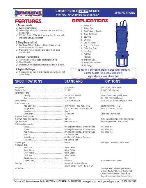
1. Enclosed Impeller Even wear components.Balanced hydraulic design for extended and even wear life of all components.28% High Chrome 650+ Brinell hardness, impeller, wear plate and casing. Back pull out design.2. Slurry Mechanical SealDual Seals of Silicon Carbide vs. Silicon Carbide running without the need for flush water.The motor is further protected by a labyrinth seal and a seal relief port.3. Premium Efficiency MotorInverter duty, air filled, copper wound/formed motor. Class H insulation.Extended run dry capabilities, minimizes the cost of operation.4. Replaceable FlangesFlanges are made from mild steel to prevent cracking the high chrome fittings.Horsepower................................................................................................15 – 1500 HP 15 – 150 HP ( SBLH Series )Discharge Size............................................................................................3” – 20”3” to 8” ( SBLH Series )Performance RangeCapacity................................................................................100 – 20,000 US GPM 100 – 4,500 US GPM ( SBLH Series )Head ......................................................................................50’ – 350’ TH10’ – 160’ TH ( SBLH Series )Solids Handling..........................................................................................1” to 5” Particle Size1.375” to2.50” Particle Size (SBLH Series)Motor NomenclatureType, Speed, HZ ..................................................................TENV Air Filled / 890-1180 / 60 HZ 350 to 1780 RPM / 50 HZ Voltage, Phase......................................................................480 V. / 3 Phase / 1.2 Service Factor 240 / 575 / 2400 / 4160 Volt Insulation ..............................................................................Class H Cable Length........................................................................33’ Standard Cable Length as RequiredMaximum Run Time in Air...................................................................... 1 Year Maximum Water Temperature................................................................180°F. +Water Jacket to Handle Hotter Temperatures Operation Mode ........................................................................................Manual or SnoreVariable Speed Drive / Float Controls Materials of ConstructionCasing....................................................................................28% High Chrome 650+ Brinell Hardness 15/3 White Iron Impeller..................................................................................28% High Chrome 650+ Brinell Hardness 15/3 White Iron Wear Plate............................................................................28% High Chrome 650+ Brinell Hardness 15/3 White IronShaft ......................................................................................416 Stainless SteelMotor Housing......................................................................Cast Iron 3/8” Minimum Thickness Fasteners ..............................................................................316 Stainless Steel Impeller Type..............................................................................................EnclosedSemi-Open - Recessed ( SBLH Series )Mechanical SealUpper Seat............................................................................Silicon Carbide Upper Rotator ......................................................................Silicon Carbide Lower Rotator......................................................................Silicon Carbide Lower Seat............................................................................Silicon Carbide Elastomers............................................................................Viton Labyrinth Seal......................................................................Cast Steel316 Stainless Steel / BronzeBearings......................................................................................................Permanently Lubricated DoubleAngular Contact 100,000 Hour B-10 LifeAccessories ................................................................................................Discharge Hose / Variable Speed Drives / Urethane Coating / Elbows in Steel or High Chrome / Control Panels / Moisture and Thermal Protection / Float Controls / Rafts.FEATURESAPPLICATIONS1.Bottom Ash2.Tailings Ponds3.Sand / Gravel / Taconite4.Clean Out Sumps5.Coke Pits6.Dredging7.Coal Pile Runoff 8.Slag Pits / Mill Scale 9.Boiler Blow Down 10.Lime Slurry 11.Red Mud Recovery12.Thickener Drain13.Precipitation Thickener 14.API SludgeSPECIFICATIONSHEAVY DUTY HIGH CHROME SLURRY PUMPThe heaviest duty submersible pump in the industry.Built to handle the most severe slurryapplications where others fail.SPECIFICATIONSSTANDARDOPTIONSFactory–4432VentureAvenue•Duluth,MN55811•218.722.9904•Fax218.722.2826••email:***************©GPM,INC.2002SUBMERSIBLE SBEW SERIES。
- 1、下载文档前请自行甄别文档内容的完整性,平台不提供额外的编辑、内容补充、找答案等附加服务。
- 2、"仅部分预览"的文档,不可在线预览部分如存在完整性等问题,可反馈申请退款(可完整预览的文档不适用该条件!)。
- 3、如文档侵犯您的权益,请联系客服反馈,我们会尽快为您处理(人工客服工作时间:9:00-18:30)。
——山东中兖矿业
PN泥浆泵使用目录
1. PN泥浆泵产品介绍 2. PN泥浆泵结构特点 3. PN泥浆泵结构组成及型号意义 4. PN泥浆泵用途及适用范围
5.PN泥浆泵结构使用注意事项 6.PN泥浆泵技术参数 7.PN泥浆泵实物图 8.PN泥浆泵维护保养
PN泥浆泵产品介绍
PN型泥浆泵过流件使用耐磨合金材料制造,寿命长。6"及6"以 下泥浆砂叶轮与轴用螺纹联接,8"及8"以上泥浆泵,泵体较大, 采用了水平中开的结构型式,拆装检修方便。400*6868*639
轴封采用一般填料密封,工作时应注入高于工作压力1公斤/厘 米²的轴封清水。 PN型泥浆泵,以传动方向看,为逆时针方向 旋转(其中1、2、3PN为顺时针)叶轮用螺纹与轴连接时,如 果反方向旋转,叶轮将从轴上脱落。
PN泥浆泵结构特点
1、结构合理、维修方便:泵头部分采用前、后开门式结构,维修时 不需拆卸管路,只需将电机向后移动,即可对泵进行拆卸和维修。 2、浓度高、无堵塞:输送纸浆浓度可达6%; 3、气蚀性能好、寿命长:实际使用寿命比普通纸浆泵可提高2-3倍; 4、高效、节能:运行效率比普通纸浆泵平均高出3-10个百分点,节 能、降耗达15-30% 5、叶轮和护板的间隙可以及时调整,保持较高效率工作。泵以上的 泵体较大,采用了对开的结构形式,拆装检修方便
PN泥浆泵结构组成及型号意义
PN泥浆泵由10大部分组成,分别是:泵体、泵盖 、叶轮、护板、填 料箱、轴、托架后盖、托架、冷却管、泵座。
PN泥浆泵型号意义: 如2PN泥浆泵
2---吐出口径(毫米数被25除所得值)
P---杂质泵
N---泥浆
PN泥浆泵用途及适用范围
1、 PN型泥浆泵系单级单吸泥浆泵(分立式、卧式)具 有寿命长、结构简单、运行可靠等特点。输送最大浓度 按重量计为50%。 2、 用于矿山、冶金、市政建筑、化工、印染等吸送有 流砂、小泥块泥浆、污浊液体之用。 3、 用于农村的河泥、池塘泥液、粪便、浆状饮料的吸 送;亦可用于城市工厂输送矿砂液,地下道吸黄砂子及 泥浆等。
PN泥浆泵结构使用注意事项
1、 PN型泥浆泵系单级单吸泥浆泵(分立式、 卧式)具有寿命长、结构简单、运行可靠等 特点。输送最大浓度按重量计为50%。 2、 用于矿山、冶金、市政建筑、化工、印 染等吸送有流砂、小泥块泥浆、污浊液体之 用。 3、 用于农村的河泥、池塘泥液、粪便、浆 状饮料的吸送;亦可用于城市工厂输送矿砂 液,地下道吸黄砂子及泥浆等。
PN泥浆泵技术参数
PN泥浆泵实物图
PN泥浆泵维护保养
(1)检查泵及管路各接合处有无松动现象,用手转动泵试看水。 (3)向泵加注引水 (4)关好出水管的闸门和出口压力表。 (5)开动电机,当泵正常动转后,打开出口压力表,逐渐打开闸阀,视其显示适当压力为止。同时检 查电机负荷情况。 (6)尽量控制泵的流量和扬程在泵标牌上注明的范围内,保证泵在高效率点附近长期运转,以便获得 最大的节能效果。 (7)泵在运转过程中,轴承温升不超过环境温度35℃,最高温度不超过80℃。 (8)泵在运行过程中,如发现有异常声音,应立即停车检查原因。 (9)泵要停止使用时,先关闭闸阀,压力表,然后停止电机。 (10)注意轴承的润滑情况,定期向轴承室注入润滑脂。 (11)泵在寒冬季节使用时,停车后须将泵体下部放水丝堵拧开将水放净,防止冻裂。 (12)泵长期使用,须将泵全部拆、擦干水份,将转动部件及结合处涂以油脂装好,妥善保存.
谢谢观赏
WPS Office
中兖矿业