GPS玻璃钢天线规格书
GPS.BD2(北斗)四臂螺旋天线规格书

GPS、BD2(北斗)多频四臂螺旋天线规格书
前言:随着现代无线通讯事业的发展,卫星导航
定位系统在人们的生活中起着越来越重要的作用。
从而
对GPS以及北斗天线的需求越来越大,深圳微航磁电技
术有限公司基于新型高分子介质材料,研发出了现有的
GPS+BD2(北斗)四臂螺旋多频天线。
一.产品说明
本产品属于3D构型天线,放置空间任何位置时增益稳定
二.产品类别
天线类别:四臂螺旋多频天线
三.产品编码
WH-S-GB-D:GPS+BD2四臂螺旋多频天线
四.产品性能
GPS性能:
频率范围:1575.42±1.023Mhz
极化方向:右旋圆极化
增益:-2dBi
电压驻波比≤1.5
阻抗:50Ω
轴比:≤6dB
不圆度:±2.0dB
BD2性能:
频率范围:1561.42±3.58Mhz
极化方向:右旋圆极化
增益:-2dBi
电压驻波比≤1.5
阻抗:50Ω
轴比:≤6dB
不圆度:±2.0dB
五.产品性能指标
增益
电压驻波比
Marker1:1575.42Mhz(1.8) Marker2:1561.098Mhz(1.3)
阻抗:50Ω
Marker1:1575.42Mhz
五.产品外形尺寸六.焊接方式
七.引脚方式。
无人机北斗天线规格书
GHT02002ZCA天线规格书2015年7月北京旋极星达技术有限公司1.概述GHT02002ZCA是一款集B1、L1、B3的天线,可广泛应用于弹、箭、星、船等军事领域。
该天线采用多馈点设计,保证天线相位中心和几何中心的重合,提高测量的精度。
内置低噪声放大模块,采用前置及多级滤波器滤除干扰信号,保证在恶劣电磁环境下正常工作。
体积小巧,重量轻。
2.技术性能指标1)工作频率和带宽:B1:1561+2.04MHzL1:1575+1.02MHzB3:1268+10.23MHz2)极化方式:B1L1B3:右旋圆极化3)天线波束:方位0°~360°;仰角20°~90°4)不圆度:B1L1B3:±1.5dB,仰角≥20°5)极化增益:B1L1:≥-4.5dBi(仰角20°,B1L1全频段)≥2.5dBi(仰角70°,B1L1全频段)B3:≥-5dBi(仰角20°,B3全频段)≥2dBi(仰角70°,B3全频段)6)轴比:B1L1:≤8dB(仰角20°,B1L1全频段)B3:≤6dB(仰角20°,B3全频段)7)电压驻波比:B1L1、B3≤1.5(50Ω)8)检测要求:检测任意一端口指标时,其余端口加50Ω负载3.环境适应性(1)温度要求工作温度:-50℃~+60℃贮存温度:-55℃~+70℃(2)湿热满足GJB150.9A-2009规定的湿热试验要求。
(3)振动要求满足GJB150.16A-2009环境试验方法振动试验中规定的振动条件。
(4)冲击要求能承受GJB150.18中“实验五基本设计试验”半正弦波,峰值加速度20m/s2,脉冲持续时间11ms的冲击,而具有保持结构和性能完好的能力,两次冲击间隔时间60ms。
4.天线尺寸项目特性1.1体积(Dimension)48*48*11.2mm1.2B1L1体积(Dimension)35*35*4mm1.3B3体积(Dimension)44*44*3mm1.4线长(Cable Length)100mm1.5接头(Connector)MMCX公弯头5.低噪放指标No.项目(Item)特性环境试验后允许误差(Post Environmental Tolerance)4.1低噪放增益(LNA Gain)32±2dB±0.5 4.2噪声系数(Noise Figure)≤2.0dB——4.3输出驻波(VSWR)≤2±0.3 4.4输入驻波(VSWR)≤2±0.3 4.5增益平坦度(Gain Flatness)±2dB±0.54.6输出P1dB压缩点(Pout at1dB GainCompression Point)≥0dBm——4.7工作电压(LNA Drain Voltage)3.3-12VDC——4.8工作电流(LNA Current Consumption)≤48mA——4.9差分传输延迟(delay)<5ns——5.0带外100M抑制(band rejection)40dB——。
GPS玻璃钢天线规格书
底温试验
COLD TEST
在-40+2℃ 环境中放96小时,再置放正常环境中30分钟后进行测试
-40+2℃ for 96hours, after keep in normal condition for 30mim the to test.
5、驻波测试(STATIONARY WAVE PATTERN)
辐射方向RadiationDirection
垂直
最大输入功率Max Input Power (w)
100
机械指标Mechanical Speபைடு நூலகம்ifications
天线长度Antenna Length (mm)
100MM
连接器型号Connect Type
N型公头公针(用户指定)
外壳颜色Radome Color
以1.10mm和振幅和33.30Hz/sec振动频率以X轴方向振动120分钟,Y轴方向振动120分钟,Z轴方向振动240分钟.
无任何现象显示电器性能之损坏.
4、耐久性测试(DURABILITY)
1
盐雾试验
SAIT SPRAY TEST
盐水喷雾试验:依GB1266-86标准
蒸馏水:一次蒸馏
PH6.5~7
遥摆1000次后测试特性无任何现象显示电器性能之损坏.
2
强度测试
STRENG TEST
一个15磅之静负荷施加放线端底部持续一分钟.
无任何现象显示机械及电器性能之损坏.
3
拉力测试PULLING FORCE
用拉力计接头及线财间进行拉力测试.
可承受拉力为7Kg无任何现象显示电器性能之损坏.
4
振动测试VIBRATION TEST
MARUWA MWSL1252 GPS L1 天线规格书说明书

1.ScopeThis specification applies to the MARUWA MWSL1252 GPS L1 antenna which is intentionally designed to resonate in free-space at 1593.5MHz so that it can be tuned by the embedding configuration to the GPS L1 frequency: 1575.42MHz.The MWSL1252 part is designed for applications where packaging will cause a moderate level of down-tuning. Forapplications with a higher degree of detuning the MWSL1251 part should be selected.2.SpecificationsMinimum Typical Maximum UnitPart Number MWSL1251 (MARUWA dwg N o: MEFP125X0022A140101)Type Dielectric-loaded Quadrifilar HelixConnector Type Refer to embedding information / connection diagramsFree Space Frequency 1593.5MHzEmbedded Frequency 1575.42MHzPolarisation Right-hand Circular PolarisedIntegrated Gain (evaluation PCB)-3.0dBic at zenithBeamwidth >115DegreesBandwidth (3dB)15MHzAxial Ratio <1.5at zenithVSWR <2.0:1 2.3:1Impedance 50ΩOperating Temperature -402085°C Overall Dimensions Refer to mechanical drawings mmWeight 7.0grams3.DimensionsBasic MWSL1252 form:Rev.Date Description Approved Checked PreparedK.Inagaki F.Frimpong Product Specification (Preliminary)MARUWA Antenna ProductsDocument №MEPS-12520042150101MWSL12520103 Feb. 15Issue of the first edition O.Leisten Notes:1.MARUWA Europe assembly drawingMEFP125X022******* applies.2. Units in mm.3. For connection layout and pad-size, through-hole andconnector details please refer to pad layout and designationdefinitions.MWSL1252S form with loosely fitting translucent sleeve.Notes:1.MARUWA Europe assembly drawingMEFP125XS28A140101 applies.2. Units in mm.3. Transluscent sleeve unit: METC12XX028A140101 shownfitted but actually shipped separately.4. For connection layout and pad-size, through-hole andconnector details please refer to pad layout and designationMWSL1252R form with loosely fitting black radome cap.Notes:1.MARUWA Europe assembly drawingMEFP1252R04B140101 applies.2. Units in mm.3. Black cap/radome unit: METC120X158140101 shownfitted but actually shipped separately.4. For connection layout and pad-size, through-hole andconnector details please refer to pad layout and designation0103 Feb. 15Issue of the first edition K.Inagaki F.Frimpong O.Leisten Rev.Date Description Approved Checked Prepared4.Product DescriptionTypical Gain PatternThe MWSL1252 GPS L1 miniature dielectric-loaded antenna uses MARUWA’s distinctive materials technology to provide high circularly-polarised gain in a small size for particularly tightly integrated applications.It enables excellent GPS performance in such tightly integrated devices that require good positional eful gain uplift, due to near-field reflections, can be achieved throughinstallation according to MARUWA design guidelines.The MWSL1252 antenna has a sharp filtering response and is particularly suitable for applications where:*The device is hand-held, body-worn, or otherwise surrounded by materials of high relative dielectric-constant which would de-tune other antennas.* The antenna is installed in close proximity to other antennas sharing the same device housing and ground-plane: for example Bluetooth®, WiFi, LTE,WiMax and other cellular radio antennas.* The antenna must fit into a very small installation volume with close proximity to other components and little or no space available for a ground-plane.* The orientation of the device is random.* The antenna must be embedded into the device.The MWSL1252 antenna is balanced, which isolates it from the device ground enabling it to reject common-mode noise present on the device ground-plane. The construction and materials of the antenna constrain its near-field region to occupy a very small volume so that materials near theantenna cause negligible de-tuning effects. Therefore the antenna maintains its pattern and efficiency in the presence of dielectric loading. As a dielectric-loaded antenna the MWSL1252 has a stablefiltering effect; attenuating signals from common cellular and ISM frequency bands by as much as 30dB without external filtering.0849096180-96-90-84Elevation Gain (G θ) For Azimuth (φ)0264270276Azimuth Gain (G φ) for Elevation (θ)Rev.Date Description Approved Checked PreparedMARUWA Antenna ProductsDocument №MEPS-12520042150101MWSL12520103 Feb. 15Issue of the first edition K.Inagaki F.Frimpong O.Leisten A second mode of installation is one in which the MWSL1252 isembedded into the housing with features surrounding theantenna causing a moderate degree of down-tuning. Though it iselectrically isolated from the device ground plane, through theaction of an integrated balun, the MWSL1252 antenna can beexpected to increase efficiency by up to 100% when integratedinto a ground plane due to constructive near-field signalreflections. This product is generally used in a class of smallportable devices that have slim styling so that there is no spacefor a ground-plane that is laterally disposed with respect to theantenna-axis. It is therefore specified as embedded into aground-plane that is co-planar with the antenna axis.The MWSL1252 is designed for applications with embedding configurations that tune theantenna from the free-space resonant frequency of 1593.5MHz to the GPS L1 frequency of1575.42MHz. Such configurations include the co-planar ground-plane as shown above with10mm offset between the circuit-board copper-ground plane and the side of the antennatogether with further de-tuning caused by the plastic housing of the product.For applications with more tight embedding MARUWA offers the MWSL1251 part which is tuned to a free-space frequency of 1603.5MHz.The MARUWA MWSL1252 antenna is designed for two modes ofinstallation.The first (and preferred) configuration is as a stand-aloneextenally mounted antenna (outside of the housing) with the black-capradome fitted (MARUWA part number: METC120X0158140101). Theantenna can be incorporated into a stand-alone package with a co-axialconnector output as might be configured in a screw-on packageformat. In such a configuration the MWSL1252 part may be embeddedwithin a plastic over-moulding. Alternatively the antenna can beconnected to an internal circuit board using the connection pads butwith the product housing closing into the groove of the black capradome. As an another alternative the customer may choose to designa radome of a different style. Such a design must be implemented witha suitable low-loss material which has the same dielectric loadingeffect as the MARUWA METC120X0158141010 black cap/radome.Typical Impedance Response Typical Return Loss Response Filtering Response Rev.Date Description Approved Checked PreparedMARUWA Antenna ProductsDocument №MEPS-12520042150101MWSL1252O.Leisten Cellular 900GPS L1Cellular 18003G Rx ISM 2.4190021102170-29-32-30-40-38-46-40-3K.Inagaki F.Frimpong 0103 Feb. 2015Issue of the first edition Frequency (MHz)S 21 (dB)24002480860970157517001800-26-36A set of match loci for a typical MWSL1252antenna is shown as plotted on a Smith chartwhich is normalised to 50 . The dielectric-loaded structure of the antenna causes thematch characteristic not to change significantlywhen is close proximity to the human body. Forexample the |S 11| response is remarkablyunchanged as a human hand is brought as closeas 5mm from the antenna.This MARUWA dielectric-loaded antenna technology delivers a major advantage with regard toimmunity to de-tuning when brought into close proximity to human tissues and other "in-use"causes of dielectric loading. The MWSL1252 antenna retains efficiency and polarisation near the human body. Conventional antennas may lose 5-10dB of gain or efficiency in similarcircumstances of use.The frequency stability of the MWSL1252antenna is further illustrated in the graph ofreturn-loss magnitude (in dB)for fourdifferent levels of dielectric loading (mmoffset from a phantom hand). Once again itdemonstrates that minimal detuning occursuntil the antenna is within 10 mm of thephantom hand.Page 6/6Embedding Information Pad Layout and designation Pad Number Function 1Ground 2Signal 3GroundDimensionsmm ± 0.1A3.2B1.45C1.7D0.5E1.5F3.5G 3.5Ordering Guide for the MWSL1252 AntennaMaruwa PartDescription MOQ Pack Size MWSL1252 with PBC-feed connection.MWSL1252SMWSL1252 with sleeve (for embedded use).Please note that when MWSL1252S or MWSL1252R parts are ordered the sleeve/radome parts shall be delivered in separate packaging and will not be fitted to the MWSL1252 product. The radome and sleeve parts are designed to fit loosely.5.Notes1. The contents of this document assure the characteristics and quality of the antenna components themselves.2. Please ensure that they work correctly in the installed configuration and method of use of your equipment.Rev.Date Description Approved Checked PreparedProduct Specification (Preliminary)MARUWA Antenna ProductsO.Leisten Document №MEPS-12520042150101MWSL125201K.Inagaki MWSL1252R MWSL1252 with radome (for external use).400400400400400400MWSL1252Issue of the first edition 03 Feb. 2015 F.Frimpong A typical installation into a plastic housing isshown. It embodies the combination of ahand-soldered electrical connection to thehost PCB with mechanical support, in theform of plastic cradle-ribs, to implement ashock-resistant structure. Of course it isimportant to ensure that the assembly is notunder strain when the parts are fittedtogether. If accurate assembly jigs areavailable, the antenna can be soldered to theboard and thereafter the board-assemblycan be fitted into the housing. Alternativelythe MWSL1252 can be soldered to the boardwhich is itself fitted into the housing. Theinstallation is completed when the lid half ofthe housing, with the opposing antenna ribs,is fitted. Further installation information canbe obtained from MARUWA's integrationguideline documents.The "ground exclusion area" applies to all PCB layers. Ground-plane within this regiondegrades the 50Ωmatch.123F D EG AA B B C Ground。
(整理)卫星天线4.5米天线说明书.

精品文档SCE-450C型4.5米天线安装、使用、维护手册西安航天恒星科技股份有限公司手册使用说明 :SCE-450C型天线是实现C波段与Ku波段共用的卫星地球站天线。
使用时,只需根据不同的使用情况换上C波段馈源或Ku波段馈源即可。
《SCE-450C型4.5米天线安装、使用、维护手册》针对C波段与Ku波段的使用,除了馈源安装方式(附图13A为C波段馈源,13B为Ku波段馈源)和天线电气特性指标不同外,其余内容全部通用。
精品文档安全方面的注意事项安全声明:以下声明适用于本手册的全过程。
在天线安装前必须仔细阅读本手册,并切实按照规定的步骤及方法进行操作,以保障人身及设备的安全。
1. 必须严格按照要求制作地基,只有在地基达到预定的强度后,方可对天线进行安装。
2. 在吊装过程中,应注意人员及设备的安全;保证设备在吊装中平稳。
3. 在无吊车情况下安装,应特别小心,以确保人身及设备的安全。
4. 在首次运行前,应对所有有润滑要求的部件进行润滑。
其中,减速器用指定的润滑油润滑;方位轴、俯仰轴用稀油注入油杯润滑;丝杠螺母用润滑脂润滑。
5. 在调整限位器工作时,应特别注意不要使丝杠脱出减速器,尤其是俯仰丝杠脱出减速器将造成天线严重损坏。
在方位、俯仰二丝杠的左,右(或上,下)极限位置限位器安装完毕后,首先进行试运行,确保限位器工作无误。
6. 天线具有软件和硬件两重限位保护。
为确保天线使用安全,在转动天线时,应使用ACU,并将软件限位设置在硬件限位之前。
7. 手轮用后应取下,并装上蜗杆轴盖,切勿将手轮套在蜗杆轴上,以免电动时,发生意外事故。
8. 应注意检查波纹喇叭封口材料是否破损或漏水,尤其是在冰雹或大雨之后,若波纹喇叭口漏水,将影响系统正常工作,严重时造成HPA或SSPA损坏。
若封口材料破损,应及时更换。
精品文档1. 4.5米天线简介SCE-450C型4.5米卫星通信天线是西安航天恒星科技实业(集团)公司研制生产的卫星通信地球站天线。
卫星天线4.5米天线说明书
SCE-450C型4.5米天线安装、使用、维护手册精彩文档精彩文档西安航天恒星科技股份有限公司手册使用说明 :SCE-450C型天线是实现C波段与Ku波段共用的卫星地球站天线。
使用时,只需根据不同的使用情况换上C波段馈源或Ku波段馈源即可。
《SCE-450C型4.5米天线安装、使用、维护手册》针对C波段与Ku波段的使用,除了馈源安装方式(附图13A为C波段馈源,13B 为Ku波段馈源)和天线电气特性指标不同外,其余内容全部通用。
安全方面的注意事项安全声明:以下声明适用于本手册的全过程。
在天线安装前必须仔细阅读本手册,并切实按照规定的步骤及方法进行操作,以保障人身及设备的安全。
1. 必须严格按照要求制作地基,只有在地基达到预定的强度后,方可对天线进行安装。
2. 在吊装过程中,应注意人员及设备的安全;保证设备在吊装中平稳。
3. 在无吊车情况下安装,应特别小心,以确保人身及设备的安全。
4. 在首次运行前,应对所有有润滑要求的部件进行润滑。
其中,减速器用指定的润滑油润滑;方位轴、俯仰轴用稀油注入油杯润滑;丝杠螺母用润滑脂润滑。
5. 在调整限位器工作时,应特别注意不要使丝杠脱出减速器,尤其是俯仰丝杠脱出减速器将造成天线严重损坏。
在方位、俯仰二丝杠的左,右(或上,下)极限位置限位器安装完毕后,首先进行试运行,确保限位器工作无误。
6. 天线具有软件和硬件两重限位保护。
为确保天线使用安全,在转动天线时,应使用ACU,并将软件限位设置在硬件限位之前。
7. 手轮用后应取下,并装上蜗杆轴盖,切勿将手轮套在蜗杆轴上,以免电动时,发生意外事故。
8. 应注意检查波纹喇叭封口材料是否破损或漏水,尤其是在冰雹或大雨之后,若波纹喇叭口漏水,将影响系统正常工作,严重时造成HPA或SSPA损坏。
若封口材料破损,应及时更换。
精彩文档1.4.5米天线简介SCE-450C型4.5米卫星通信天线是西安航天恒星科技实业(集团)公司研制生产的卫星通信地球站天线。
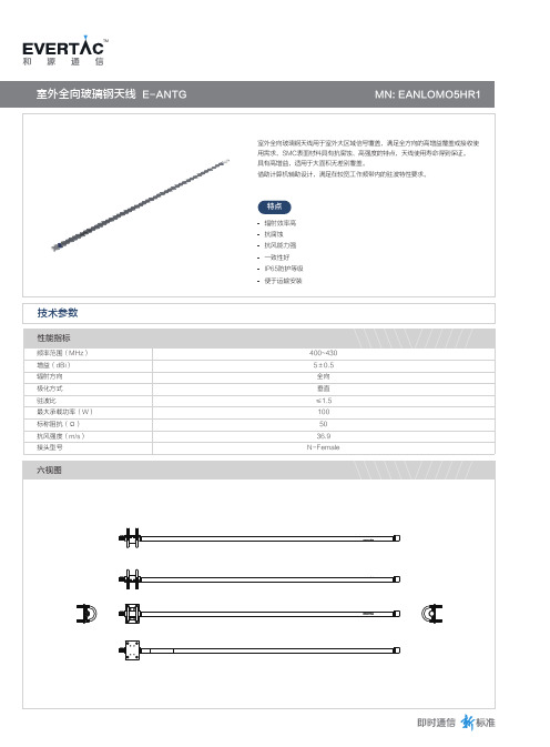
室外全向玻璃钢天线E-ANTG
TM
-20~55℃ ≤95% IP65
1200mm 20mm
1230*93*35mm 1kg
1 2 1 1 1 1 如欲了解更多产品信息,请致电400-615-6850或浏览网址
TM
室外全向玻璃钢天线 E-ANTG
技术参数
性能指标
频率范围(MHz) 增益(dBi) 辐射方向 极化方式 驻波比 最大承载功率(W) 标称阻抗(Ω) 抗风强度(m/s) 接头型号
六视图
MN: EANLOMO5HR1
室外全向玻璃钢天线用于室外大区域信号覆盖,满足全方向的高增益覆盖或接收使 用需求,SMC表面材料具有抗腐蚀、高强度的特点,天线使用寿命得到保证。 具有高增益,适用于大面积无差别覆盖。 借助计算机辅助设计,满足在较宽工作频带内的驻波特性要求。
特点 辐射效率高 抗腐蚀 抗风能力强 一致性好 IP65防护等级 便于运输安装
400~430 5±0.5 全向 垂直 ≤1.5 100 50 36.9
N-Female
工作环境
温度 相对湿度 防护等级
机械规格
产品长度 产品直径 包装尺寸(L*W*H) 重量
包装规格
室外全向玻璃钢天线*1 抱箍 安装支架 安装板 合格证 安ቤተ መጻሕፍቲ ባይዱ指南
GPS天线数据

一、产品型号Product Model GZXT-A二、介质天线 Dieletric Antenna中心频率Center Frequency 1575.42MHz±3 MHz电压驻波比V.S.W.R 1.5:1带宽Band Width ±5 MHz阻抗Impendence 50 ohm最高增益Peak Gain >3dBic Based on 7×7cm ground plane 增益范围Gain Coverage >-4dBic at –90°<0<+90°(over 75% Volume) 天线极化Polarization RHCP三、放大器/滤波器LNA/Filter放大器增益LNA Gain(Without cable) 28dB Typical噪声系数Noise Figure 1.5dB滤波器带外衰减Filter Out Band Attenuation (f0=1575.42 MHZ)7dB Min f0+/-20MHZ ;20dB Min f0+/-50MHZ;30dB Min f0+/-100MHZ输出电压驻波比V.S.W.R <2.0直流电压DC V oltage 3V , 5V, 3V to 5V或其他直流电流DC current 5mA ,10mA Max四、结构Mechanical重量Weight <105(克)gram外型尺寸Size 35×33×13mm电缆Cable RG174 5 meters 或3 meters连接器型号Connector SMA/SMB/SMC/BNC/FME/TNC/MCX /MMCX 固定方式Mounting 磁性Magnetic base/粘贴stiking外壳颜色Housing 黑Black五、环境Environmental工作温度Working Temp -40℃~+85℃振动Vibration Sine sweep 1g(0-p)10~50~10Hz each axis湿度Humidity Humidity95%~100%RH防水Weatherproof 100%Waterproof测试数据及曲线图1.天线2.方向图(DAE1575R2540A指向性测试图)天線指向性(axial ratio):藍色字體處數值控制在3dB 以內 -1.000 0.000-0.266 -146.496 -1.000 0.000 -0.197 -48.904 0.000 0.000 -0.599 -43.376 0.000 0.000 -0.369 55.557 1.0000.0000.00062.1161.0000.0000.000160.098Gain :(plot)+47= -43.513+47 =3.487Gain :(plot)+47= -43.692+47 =3.3083.滤波器广州鑫图科技有限公司。
GPS授时天线性能规格及安装方式
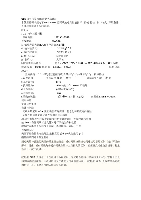
GPS信号接收天线(蘑菇头天线)本使用说明书规定了GPS-3000A型天线的电气性能指标、机械特性、接口方式、环境条件、设计与制造及天线的安装。
2.要求3.2.1 电气性能指标频率范围: 1575.42±5MHz天线增益: 38±2dBic. 低噪声放大器(LNA)噪声系数: ≤2.5dBd. 输入驻波比: VSWR≤2.0:1e. 输出驻波比: VSWR≤2.5:1f. 极化方式: 右旋圆极化g. 前后比: 大于10h.防雷击浪涌特性符合:GB/T 17626.5-1999 idt IEC 61000-4-5:1995 标准 浪涌波形CWG 组合波(1.2/50us, 8/20us) 峰值电压2000Vi. 直流供电: 3.5~6V(通过射频电缆,内导体为"+",外导体为"-") 机械特性a.温度范围: 工作温度-40℃~+70℃; 储存温度-55℃~+85℃b.工作湿度: 95%c.抗风能力:45m/s能工作,60m/s不破坏d.天线体积: φ110×113(mm^3)e.天线重量: 2kgf.天线安装管:φ28×300 2.3 接口方式: N型座/FME/BNC/TNC使用环境:室外自然条件设计与制造天线外罩采用ASA模压成型,有耐腐蚀、防老化和强度高的特性天线及低噪放关键元器件采用进口元器件.外罩与安装座用硅胶密封圈及硅酮密封胶封装 性能检测与验收按《GPS有源天线工艺文件》进行天线生产和检验。
将验收合格的天线存放于库房,要求阴凉、通风、干燥天线的安装天线不要安装在电线附近,抱杆直径φ30~60,优先选用φ48抱箍的紧固螺母拧紧防松授时天线与普通的天线的最主要差别是,授时天线应该长时间连续可靠地工作,减少环境的影响,因此,授时天线与普通的天线在设计上有很大的区别,必须重点考虑防雷设计、稳定性设计、抗干扰设计。
深圳市蝙蝠无线技术有限公司 GPS 贴片天线 BWGPSZWX46-38JL1000 产品规格承认书

承认厂商:(Recognized制造厂商(Manufacturer)产品名称:GPS贴片天线(Description)产品选型表:(Product Type)型号说明备注BWGPSZWX46-38JL1000SMA内螺内针线长可选配供应商承认签栏制表者审核者核准者客户承认栏审核者核准者1.2AntennaPicture(可定制)*注:因天线功能较为敏感,主体周边机构有变更请通知我们评估。
上图型号:BWGPSZWX46-38JL10002.Electrical S pecification2.1Test EquipmentA.VSWR and input impedance:Agilent8753/E5071Network AnalyzerB.Antenna gain and efficiency:ETS three-dimensional anechoic chamber2.2Test Setup2.2.1Frequency Range2.2.2VSWRStep1:The antenna is arranged on the customer provided test fixture.Step2:The VSWR of the antenna is measured via Agilent8720/8753Network Analyzer(see figure.1).Figure.12.2.3Radiation pattern and GainA.The3D chamber provides less than-40dB reflectivity from800MHz to6GHz and a40cm diameterspherical quiet zone.The measurement results are calibrated using both dipoles and standard gainhorns(see figure.2).B.The antenna under tested is arranged in the turned table and a decoupling sleeve is used to reducefeed line radiation(see figure.3).C.The measured results of the radiation patterns and antenna gain are obtained from the controlsystem and showed on the monitor(see figure.4and5).Figure.2Figure.3Figure.4Figure.53.Performance Data3.1Passive dataVSWR(电压驻波比)/Return Loss(回波损耗)/Smith Chart(史密斯圆图)*注:以上为实测数据,仅供参考;因天线功能较为敏感,主体周边机构有变更请通知我们评估。
Abracon 外部组合LTE GPS天线说明书
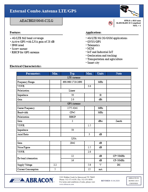
MSL = 1
1990 MHz
2170 MHz
2670 MHz
Packaging
Each 70 x 32 x 15 cm size carton includes 100 pcs antenna, weighs 15 kg.
ATTENTION: Abracon LLC’s products are COTS – Commercial-Off-The-Shelf products; suitable for Commercial, Industrial and, where designated, Automotive Applications. Abracon’s products are not specifically designed for Military, Aviation, Aerospace, Life-dependent Medical applications or any application requiring high reliability where component failure could result in loss of life and/or property. For applications requiring high reliability and/or presenting an extreme operating environment, written consent and authorization from Abracon LLC is required. Please contact Abracon LLC for more information.
Ø50.0 x 48.0 mm
卫星天线3米天线说明书

SCE-300B型3米C、Ku波段天线安装、使用、维护手册西安航天恒星科技股份有限公司手册使用说明SCE-300B型天线是实现Ku波段与C波段共用的卫星地球站天线。
使用时,只需根据不同的使用情况换上Ku波段馈源或C波段馈源即可。
《SCE-300B型3米Ku、C波段天线安装、维护、使用手册》针对Ku波段与C波段的使用,除了馈源安装方式和天线电气特性指标外,其余内容全部通用。
安全声明在天线安装或使用前,必须仔细阅读本说明,并切实按照规定的步骤和方法进行操作,以保障人身安全及设备的安装精度。
1.天线简介SCE–300B型3米卫星通信天线是西安航天恒星科技股份有限公司研制生产的卫星通信地球站天线。
该天线是高性能的双修正环焦型天线,由于采用了计算机优化设计和先进的制造工艺,因而该天线具有高增益、低旁瓣、高极化鉴别率、小电压驻波比等良好特性。
该天线主反射面是赋形抛物面,由八块瓜瓣样的铝合金面板组成,每块面板均采用高精度拉伸成型蒙皮与高刚度骨架铆接而成,这种复合结构的面板保证了天线重装精度,减少了安装工作量,使天线有很强的抗风能力和足够的强度。
天线副反射面及馈源系统均由数控车床加工成型,表面处理采用导电阳极化、热喷锌后烤漆(包括底漆和面漆)的处理工艺。
天线全部钢结构部件采用热浸锌或热喷锌后喷漆的表面处理工艺,全部连接用标准件采用不锈钢件,增强了它的防腐蚀能力,使天线的使用寿命大于15年。
天线座架形式采用有限可控立柱式俯仰-方位型,保证天线系统具有0°~360°的方位转动和 0°~ 90°的俯仰转动范围。
由于天线口径较小,一般采用手动调节;若使用方有特殊要求,也可提供电动调节。
天线系统由天线和馈源两大部分组成。
由于天线波束较窄,手动型天线备有方位微调机构,确保准确对星。
天线部分由主反射面、副反射面、天线座架、辐射板等组成(见附图1:3m天线结构图)。
馈源部分由波纹喇叭、双工器两部分组成。
全向天线说明书
GWT-2000-S-A型船用全向有源电视广播接收组合天线使用说明书GWT-2000-S-A型船用全向有源电视广播接收组合天线GWT-2000-S-A型船用全向有源电视广播接收组合天线采用全新概念设计是专为舰船或海上移动场合设计全方向广播、电视信号接收天线。
适用频率:AM0.3-20MHZ。
FM85-108MHZ、TV48-890MHZ全球各地均可使用。
本天线外形呈流线形,美观新颖,体积小,重量轻,安装方便,外壳采用玻璃钢结构,机械强度高,安全可靠。
适用各种海上条件的长期使用,及远航时接收效果。
主要技术参数:1.FMAM接收频率:FM85-108MHZ、AM0.3-20MHZ2.输出增益:≥20DB接收频率:48-895MHZ4.输出增益:>16db5.接收方向:水平面内天线呈全方向性(全向性不均度≤4db)6.电源电压:AC220V±10%7.输出电压:DC12V(可调)8.工作电流:100-300MA9.标称阻抗:75Ω10.环境:-20℃+60℃11.净重:≤5kg12.安装孔:Ø50m/m≤该天线接收分为两个部分:1、AMFM由四根振子呈放射形,信号放大后独立输出。
2、TV由六振根子呈弧形组合,信号经放大后送到电源盒。
一、由该系统之间配接合理,关键部位采用进口元件,故接收灵敏度高,噪声低,适用各种航海条件下的使用。
电源盒上的电位器可以在不同接收场合中进行调节,使电视图象更清晰。
安装方法:按图分别把TV、AMFM输出头接上:把整个天线套在Ø50m/m钢管上,旋紧定位螺钉。
由于本天线是全方向接收的,故在其周围3米内不应有高大建筑物和金属物,尽可避开其它接收盒发射天线包括雷达,应尽可能把天线架高,但注意要在避雷针保护区以内,确保安全。
二、AM/FM输出端在接系统箱之前,先用万用表测量阻值约在11K左右。
如发现短路则需排除,确认无误后再接系统箱AM/FM的输入端上(IN).三、TV输出端在接电源之前先用万用表测量阻值约在7K左右。
- 1、下载文档前请自行甄别文档内容的完整性,平台不提供额外的编辑、内容补充、找答案等附加服务。
- 2、"仅部分预览"的文档,不可在线预览部分如存在完整性等问题,可反馈申请退款(可完整预览的文档不适用该条件!)。
- 3、如文档侵犯您的权益,请联系客服反馈,我们会尽快为您处理(人工客服工作时间:9:00-18:30)。
产品承认书
PRODUCT SPECIFICATION
Customer’s part number:
Product description: GPS玻璃钢天线
Issue Date: 2017-8-29
Note: GPS MHz-N公头公针
客户签名
核准
审核
检查
核准
审核
检查
联系人:手机:
85+2℃for 96 hours, after keep in normal condition for 30mim the to test.
3
温试验
HUMIDITY TEST
在40+2℃90-95%RH环境中放96小时,再放在正常环境中30分钟后进行测试40+2℃90-95%RH for 96hours, after keep in normal condition for 30mim the to test.
喷雾量:1.4me80cm²/h
压缩空气压力:1Kgf/ cm²
试验相对度:98°
温度:45°~47°
压力温度:35°
测试时间:96hr
所有规格变华范围初始值30%
All characteristic range is 30% of the initial value
2
高温试验
HEAT TEST
在85+2℃环境中放96小时,再放在正常环境中30分钟后进行测试
地址:QQ:
1、产品技术指标(PRODUCT TECHNICAL SPECIFICATION)
电性能指标Electrical Specifications
频率范围Frequency Range (MHz)
1575 MHZ
输入阻抗Input Impendence (Ω)
50
电压驻波比V.S.W.R
≤2.0
增益Gain (dBi)
3 DBI
极化形式Polarization Type
垂直极化Vertical
辐射方向Radiation Direction
垂直
最大输入功率Max Input Power (w)
ห้องสมุดไป่ตู้100
机械指标Mechanical Specifications
天线长度Antenna Length (mm)
遥摆1000次后测试特性无任何现象显示电器性能之损坏.
2
强度测试
STRENG TEST
一个15磅之静负荷施加放线端底部持续一分钟.
无任何现象显示机械及电器性能之损坏.
3
拉力测试PULLING FORCE
用拉力计接头及线财间进行拉力测试.
可承受拉力为7Kg无任何现象显示电器性能之损坏.
4
振动测试VIBRATION TEST
4
底温试验
COLD TEST
在-40+2℃环境中放96小时,再置放正常环境中30分钟后进行测试
-40+2℃for 96hours, after keep in normal condition for 30mim the to test.
5、驻波测试(STATIONARY WAVE PATTERN)
以1.10mm和振幅和33.30Hz/sec振动频率以X轴方向振动120分钟,Y轴方向振动120分钟,Z轴方向振动240分钟.
无任何现象显示电器性能之损坏.
4、耐久性测试(DURABILITY)
1
盐雾试验
SAIT SPRAY TEST
盐水喷雾试验:依GB1266-86标准
蒸馏水:一次蒸馏
PH6.5~7
100MM
连接器型号Connect Type
N型公头公针(用户指定)
外壳颜色Radome Color
灰色
接头Attachment
焊接Welding
2、产品图片(PRODUCT PICTURE)
3、机械性能(MECHANICAL CHARACTERISTICS)
1
摇摆测试BENDING TEST
放离接头30CM的线端上荷重120g,固定接头后进行遥摆测试,遥摆角度左右各60度,遥摆1000次后测试特性.