3自由度并联机床的运动学和动力学研究(翻译)
3自由度并联机器人的运动学与动力学分析_刘善增

第 45 卷第 8 期 2009 年 8 月
机械工程学报
JOURNAL OF MECHANICAL ENGINEERING
Vo l . 4 5 N o . 8 Aug. 2009
DOI:10.3901/JME.2009.08.011
3 自由度并联机器人的运动学与动力学分析*
刘善增 1, 2 余跃庆 1 佀国宁 1 杨建新 1 苏丽颖 1
(1. 北京工业大学机械工程与应用电子技术学院 北京 100124; 2. 中国矿业大学机电学院 徐州 221116)
1 3-RRS 并联机器人的运动学分析
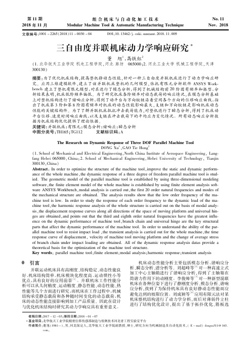
一种空间 3 自由度并联机器人的结构简图,如 图 1 所示。它由一个动平台 P1P2P3,三条支链 BiCiPi(i=1, 2, 3)和一个静平台(基座)B1B2B3 组成。其 中,动平台通过球面副(S 副)与各支链连接,静平台 通过转动副(R 副)与各支链连接,且 Bi 处转动副的 轴线与 Ci(i=1, 2, 3)处转动副的轴线对应平行。分别 建立与动平台固结的局部(动)坐标系 Pxyz 和系统 (固定)坐标系 OXYZ,如图 1 所示,坐标系的原点 P 和 O 分别位于动平台和静平台的几何中心,轴 z 和 Z 分别垂直于动、静平台向上,轴 x、y 与 X、Y 分 别平行和垂直于上、下平台的边 P2P3 与 B2B3。局部 定坐标系 Bixiyizi (i=1, 2, 3)的 xi 轴与 Bi 处转动副轴线 一致,zi 垂直于静平台 B1B2B3 向上,yi 轴同时垂直 于 xi 和 zi 轴。
一种三自由度并联动力头——A3头的运动学标定方法研究的开题报告

一种三自由度并联动力头——A3头的运动学标定方法研究的开题报告一、研究背景随着机器人技术的不断发展,各种型号和种类的机器人涌现出来,从工业机器人、服务机器人到特殊机器人等,都在不断的发展和更新。
机器人的执行器是机器人的核心部件之一,其性能直接关系到机器人的运动精度和静态特性。
而在机器人的执行器中,动力头是其核心部件之一。
A3动力头是一种常见的三自由度并联动力头,其通过输出力矩实现对机器人末端执行器的控制。
A3动力头的准确定位和定位精度直接影响到机器人的操作精度和性能,因此对其进行运动学标定具有重要意义。
二、研究内容本文将研究A3动力头的运动学标定方法,具体研究内容包括以下三个方面:1. A3动力头的运动学模型建立:通过研究A3动力头的结构和工作原理,建立其运动学模型,包括正运动学和逆运动学。
2. 运动学标定实验设计:本文将设计实验方案,利用指定位置和姿态的标定点,采用示教器手动控制A3动力头在空间中运动,记录各个关节的位置、姿态和输出力矩等数据。
3. 参数估计和误差分析:利用标定点采集的数据,利用最小二乘法对A3动力头的参数进行估计,并对估计结果进行误差分析。
三、研究意义运动学标定是机器人运动控制的基础,其对机器人的精度和性能有着重要影响。
本文将研究A3动力头的运动学标定方法,对于提升A3动力头的运动精度和定位精度,优化机器人操作性能,具有重要的应用价值。
开发和应用该方法还有望进一步推动我国机器人技术的发展及国际竞争力的提升。
四、研究方法和步骤本文将采用实验方法和数学分析方法,在建立A3动力头运动学模型的基础上,设计运动学标定实验并记录数据,利用最小二乘法对参数进行估计,并对估计结果进行误差分析。
具体步骤如下:1. A3动力头的运动学模型建立。
2. 设计A3动力头运动学标定实验,并采集数据。
3. 利用最小二乘法对A3动力头的参数进行估计。
4. 对估计结果进行误差分析并进行优化。
5. 编制研究报告。
三自由度并联机床动力学响应研究
9&:!! 9&;:"#!$
}~VH`IJKxy!
$)%! µ&$
!-'ÚÛÜ7Ä$% U«78$%Ô' ÝÞ)"%&"""$-Ô'7Ä&$ UV78$%Üß) (""!("
67>?M4ÂÅ9^Â'Æ-S²_`0(H`ÂKL?Æ892ªì * ªE01:fÇ+:4?vH`ÂÂD)*fg+,mÇ+ NZXOX PHT3A c?21W :4?ÂmfgKL?f?ÂÍÅ9 $" m[ z g ÅáâãÂ[ º >?ì*Â-[ Æ(èD2ª.Ë/faÐ ÑÂÅ9KL?/2ª?ÆhK50$/12c36-k$Dç42ª5iu U?£ ( z£ ' m[ ÂDÆ-S12×·61z0$/1712ÂÆ -SD_8Å9+ >??pH`Â9:;<(èS8ÂKL?=?ÂÆ hKç4çQ62ª5iõ.61/;<(è¡Dh§ª8Z4.Ë >mÆ2ª2 x>ÂÅ9M4^ø?Þ+x 89:H`Âmf/2ª= ;<=>(KL!%&KM!!$)))%?@ABN
1-0W0@0*+,-&/>E/*5.,W0@L&/@0&61-+00>=TS*+*))0)%*,-./01&&) *+ZM:E! 'MN+K4?LH2@$
!!-X1WHH=HIJ?1W72417=72U <=?16T417=<2@42??T42@'ZHT6W VW427,2D646E6?HIN?THDB71?<2@42??T42@' F
三自由度Delta并联机械手运动学分析及轨迹规划

第32卷第1期青岛大学学报(工程技术版)Vol.32 N o.12 0 1 7 年 2 月JOURNAL OF QINGDAO UNIVERSITY (E&T) Feb. 2 0 17文章编号:1006 - 9798(2017)01 - 0063 - 06; DOI:10. 13306/j. 1006 - 9798. 2017.01.012三自由度Delta并联机械手运动学分析及轨迹规划王娜,王冬青,赵智勇(青岛大学自动化与电气工程学院,山东青岛266071)摘要:针对自动化生产流水线普遍存在的分拣、抓取及包装等大量的重复性工作的问题,本文对三自由度Delta并联机械手进行了机械结构的分析,建立了其正逆运动学方程,推导出运动学正反解公式,进行轨迹规划,并采用M a t l a b编程求解Delta机械手的正解方程组。
同时,通过分析动平台与静平台之间的矢量关系,结合几何原理得出每个点在静坐标系中的坐标,建立了逆运动学方程组,进一步推导出了位置反解。
在反解的基础上,运用矢量关系列写正运动学方程组,结合Matlab得出了正解。
采用三次多项式插值方法对Delta机器人进行关节空间轨迹规划,并结合MatlabRobotics T o o l仿真工具箱对3个关节的角度、速度、加速度随时间的变化进行仿真分析。
仿真结果表明,正解与反解的计算结果完全对应,证明位置正解与位置反解的推导过程完全正确;关节1角度值与时间呈现正相关,关节2与关节3角度值与时间呈现负相关,验证了反解是正确的。
该规划方法对证明Delta机械手的关节空间轨迹规划是有效的。
关键词:Delta并联机械手;正逆运动学方程;关节空间;轨迹规划中图分类号:TP241.3文献标识码:A目前,Delta并联机械手是食品行业中应用最广泛和最成功的并联机械手之一。
各类行业中的自动化生产流 水线普遍存在分拣、抓取以及包装等大量的重复性工作,这些工作如果全部由人工完成,不仅劳动强度大,而且不 可避免地会造成不同程度的污染。
基于Adams的3自由度并联机构运动学分析
2 0 1 3 年 5 月
黑
龙
江
大 学
工
程
学
报
Vo 1 . 4 。 NO . 2
Ma y, 2 01 3
J o u r n a l o f En g i n e e r i n g o f He i l o n g j i a n g Un i v e r s i t y
c r e a t e d t h r o u g h t h e d a t u m c o o r d i n a t e s y s t e m a n d t h e mo t i o n v e c t o r e q u a t i o n . An d t h e a n a l y t i c a l s o l u t i o n o f t h e i n v e r s e s o l u t i o n wa s c a l c u l a t e d o n u s i n g t h e a n a l y t i c a l me t h o d . F i n a l l y t h r o u g h Ad a ms v i r t u a l p r o t o t y p i n g we g o o n t h e s t r u c t u r e o f t h e s i mu l a t i o n a n d d a t a a n a l y s i s .An d we g e t t h e p o s i t i o n d a t a o f t h e u n i o n l e v e r ,t h e mo v i n g p l a t f o r m a n d v e r i f y t h e r a t i o n a l i t y .
并联三自由度运动平台动力学分析

式中: Fz (t ) 为三个电动缸在 a,b,c 三点对动平台作 用力在质心的合力; M1(t ) 为绕 x 轴的转矩; M 2 (t) 为
绕 y 轴的转矩。由此角加速度 和 也就得到了。 根据并联三自由度运动平台系统的机械结构以及技
术指标要求: 三根电动缸总体承受载荷 W=1000kg。
2 动力学分析 由于运动平台的高度非线性和时变性,以及多体系 统的约束条件等都给计算带来巨大困难。利用广义坐标, 对动力学普遍方程进行变换,可以得到与自由度数目相 同的一组独立运动微分方程,从而使方程更简洁,便于 计算。设机构系统广义坐标 qi(t)(i=1,2,3),即为三自由度 运动仿真模拟平台的动平台质心位置的垂直位移 z 和整
基金项目:辽宁省教育厅科研项目(201114126)
1 运动平台自由度的计算 并联三自由度运动平台,其结构简图如图 1 所示。 该机构上下平台支点连接起来后是两个全等的等边三角 形 abc 和 ABC,三条边的长度均为 600mm, 上、下平台 之间用 3 根可伸缩的量程为 400mm 的电动缸相联,即
Dynamic Analysis of a 3-DOF Parallel Platform
FU Jing-shun1,LANG Xiao-hui1,ZHANG Hong2 (1.Shenyang University of Technology,Shenyang 110870; 2.Shenyang Equipment Manufacturing School, Shenyang 110026)
动 平 台 可 以 由 a,b,c 三 点 空 间 坐 标
,
和
完全确定,由于三角形 abc
为等边三角形,且三边长度不变,即 Lab=Lbc=Lca,可列 出三个约束方程:
三自由度并联机床驱动分支动力学分析
软 件 中的示 意 图 。
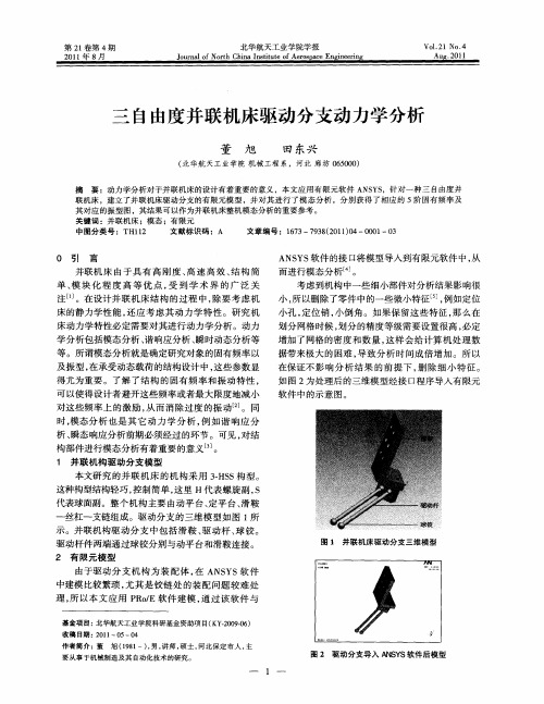
本文研究 的并 联机床 的机构采用 3H S构型。 .S 这种构型结构轻巧 , 控制简单 , 这里 H代表螺旋副 , s 代表球面副。整个机构主要 由动平 台、 定平 台、 滑鞍
—
丝杠 一支链 组成 。驱 动 分支 的三 维 模 型如 图 1 所
基金项 目: 华航天工业学 院科研基金资助项 目( Y 2 0 —6 北 K . 90 ) 0
收稿 日期 : 0 1 5—0 2 1 一O 4
作者简介 : 董
旭 (9 1 , , 18 一) 男 讲师 , 士, 硕 河北保定 市人 , 主
要从事于机械制造及其 自动化技术的研 究。
一
图 2 驱 动分 支 导 入 A S S软 件 后 模 型 NY
床的静力学性能 , 还应考虑其动力学特性。研究机 床动力学特性必定需要对其进行动力学分析 。动力 学分 析包 括模 态 分析 、 响应 分析 、 时动态 分 析等 谐 瞬
等 。所谓 模 态分 析就 是确 定研 究对 象 的 固有 频率 以
及振型 , 在承受动态载荷的结构设计 中, 这些参数显 得尤 为重 要 。 了解 了 结构 的 固有 频 率 和 振 动 特性 , 可以使得设计者避开这些频率或者最大限度地减小 对这 些频 率 上 的激 励 , 而 消 除过 度 的振 动 _ 。同 从 2 ]
考虑 到机构 中一些 细小部 件对 分析 结果 影 响很
小 , 以删 除 了零 件 中的一些微 小特 征 , 所 ]例如 定 位 小孔 , 位 销 , 倒 角 。如果 保 留这些 特 征 , 么在 定 小 那 划分 网格 时候 , 划分 的精 度等 级需要 设 置很高 , 定 必 增加了网格的密度和数量 , 这样会 给计算机处理数 据带来极 大 的 困难 , 导致 分 析 时 间 成倍 增 加 。所 以
一种三自由度并联机构的运动学分析
龙源期刊网
一种三自由度并联机构的运动学分析
作者:刘锟泽
来源:《科技资讯》2013年第05期
摘要:本文设计了一种三自由度混连机构,介绍了该机构的组成、计算了该机构的自由度,推导了并联部分的运动学正反解求解公式。
给出了具体的算例进行验证,结果对该机器人机构的设计控制等有重要的指导意义。
关键词:三自由度正反解并联机构
中途分类号:TG156 文献标识码:A 文章编号:1672-3791(2013)02(b)-0128-01
并联机构相对于串联机构具有刚度高、陈承载能力大、运动精度高、动态特性好等特点。
但并联机构的缺点也同样明显:位置正解运算复杂、工作空间小、难以实现大倾角加工以及运动特性和力特性的非线性关系、机床标定困难等。
因此混连机构的研究成为当下研究的热门课题。
混联结构机床是机床技术、并联机器人技术、现代伺服驱动技术和数控技术相结合而产生的一种新型自动化加工设备。
1 结构及其自由度
2 运动学正反解
3 算例
4 结语
本文以一种三自由度混连机构为研究对象,研究了该机构的自由度,提出了该机构的正反解计算公式,给出了具体算例,结果符合要求,计算简单,效率高。
参考文献
[1] 熊有伦.机器人技术基础[M].华中科技大学出版社,1996:1-92.
[2] 黄真,孔令富,方跃法.并联机器人机构学理论及控制[M].机械工业出版社,1997,12。
3自由度并联机床的运动学和动力学研究(翻译)

3自由度并联机床的运动学和动力学研究摘要:中国东北大学已经研制出一种用于钢坯研磨的新型3自由度并联机床。
它具有结构简单,刚度大的优点,更高的力量重量比,较大的工作空间,简单的运动学方程,没有运动的奇异位姿。
在使用相应刀具情况下该机器人可用于磨削,研磨,抛光等加工过程。
在本文中,介绍了简单的机器人的结构和自由度,运动学和工作空间,精度分析,静态和动态的分析及其相关参数。
关键词:并联机床;运动学;动力学;3自由度1.前言与传统机床相比,并联机床具有更高的精度,高刚度的优点,和更高的刚度质量比,所以近些年它得到了行业和机构大量的研究和评估。
由美国Giddings & Lewis公司研制的“六足虫”并联机床被认为是21世纪机床领域中的革命性理念。
然而这个Stewart平台存在运动耦合的缺点,并且具有复杂的运动学和构件要求十分严格。
这类少于六自由度并联机床在行业和机构也因此受到越来越多的关注。
意大利Comau研制出了一种命名为Tricept的四条腿的的三自由度并联机床。
东北大学已经开发出了一种新型三自由度的三腿平行磨削机床(图1)。
与“六足虫”并联机床相比,此三腿平行磨削并联机床具有以下优点:(1)结构简单且具有更大工作空间;(2)动力学方程简单便于控制操作;(3)在工作空间没有运动耦合状态。
图12.并联机床2.1 3自由度系统的布局该三自由度并联机构由一个移动平台,基础平台,一个平行的联动和三条腿的连接两个平台。
中间腿支链控制的移动平台的三个自由,如图2所示。
移动平台的转换是由平行连杆机构控制。
图22.2 运动学和工作空间移动平台平行于基础平台,一个坐标系统(O- X,Y,Z)选择如图2所示,这种机制的逆向运动学正解方程可以表示为:123l l l ===其中w=a-b,2m = ,n=w/2 ,a 和分别表示基础平台的两侧的长度和等边三角形状的移动平台的长度。
该机构的位置正解方程可表示为:2222222132X l l w Y w Z =-+==从公式1和2可知系统在整个工作空间无奇异位姿和运动耦合。
基于SimMechanics的三自由度并联打磨机构动力学分析与仿真

·制造业信息化·收稿日期:2011-05-16作者简介:解本铭(1956-),辽宁彰武人,教授,工学硕士。
研究方向:民航设备机电液一体化;孔维定(1984-),河南信阳人,硕士研究生。
研究方向:民航设备机电液一体化。
0引言目前电力行业中的中小型企业生产的悬锤产品,采用铸造工艺,在热镀锌工序之前需要打磨表面的毛刺,而进口专用机械设备价格较高、手工打磨效率低且劳动力成本高,为了解决上述问题,根据三自由度并联机构以其驱动元件少、造价低、结构紧凑及工作空间大等优点而有较高的实用价值[1],设计了一款新型三杆三自由度平移并联机构,改变控制程序和更换夹具可以打磨不同型号的铸件,生产效率高,能够很好的满足客户需求。
本文首先对三自由度并联打磨机构(3-P4R 并联机器人)进行了运动矩阵变换和动力学分析,计算构件及关节的质量、转动惯量、惯性力,并借助于Matlab/SimMechanics[2]工具箱的系统动态建模功能,搭建了一仿真平台。
接着在并联机器人与外界环境相互作用时,动平台在与负载接触的地方要产生末端受广义力矢量(力F 和力矩T )的条件下,对系统进行动力学仿真与分析。
1并联机构运动学分析(1)并联机构构型。
该并联机构由动平台pt 、3个P4R 型支链腿、三根滚珠丝杠组合成的导轨构成,并联打磨机构简图如图1所示。
每个支链腿都是依次由一个滑块、第一个虎克铰、一个中间连杆、第二个虎克铰组基于SimMechanics 的三自由度并联打磨机构动力学分析与仿真解本铭,孔维定(中国民航大学航空自动化学院,天津300300)摘要:针对一种新型三自由度并联打磨机构进行了运动学和动力学分析,并借助于MatLab/SimMechanics工具箱的系统动态建模功能,搭建了一精确的仿真平台。
结果表明:当并联打磨机构末端受广义力矢量作用时,在仿真平台上对系统进行Lagrange 方法的动力学仿真分析,示波器跟踪动平台中心点的位置、速度及加速度,从而获得驱动关节力和动平台位姿的函数曲线关系,可验证所设计机构的动力学特性是否理想。
3自由度Delta并联机构的特性分析与运动仿真的开题报告

3自由度Delta并联机构的特性分析与运动仿真的开
题报告
一、选题背景及研究意义
Delta并联机构广泛应用于工业生产中的装配、包装、取料等领域。
该机构具有高精度、高刚度、高速度等优点,被广泛应用于生产线上。
近年来,随着技术的不断进步,Delta并联机构的应用范围不断拓展,因此对其特性分析及运动仿真的研究具有重要的意义。
本次研究将采用MATLAB等软件工具,对Delta并联机构进行分析,并开展运动仿真,为机器人设计及工业生产提供参考。
二、研究内容
1. Delta并联机构概述
2. Delta并联机构的运动学分析
3. Delta并联机构的动力学分析
4. Delta并联机构的运动仿真
5. Delta并联机构的参数优化
三、研究方法
本研究将采用基于MATLAB的数学建模方法,对Delta并联机构进
行运动学和动力学分析,并进行运动仿真。
其中,运用动力学定理对Delta并联机构进行分析,得出其性能参数,并结合实验数据对其进行优化。
四、预期结果及意义
通过对Delta并联机构进行分析,可以获得其运动学和动力学特性,为机器人设计及工业生产提供参考。
同时,通过运动仿真和参数优化,可以为Delta并联机构的实际应用提供有效的技术支持。
三自由度并联机器人运动学分析与研究
吴培栋,张振久,龚爱平
( 深圳信息职业技术学院 智能制造与装备学院,深圳 518172)
摘摇 要:主要对三自由度 Delta 并联机器人进行逆运动学研究。 首先在 Delta 机器人的动平台和静平台上分别建立 动坐标系和静坐标系,根据其动静平台及各运动支链的结构特征建立其矢量方程,并由此推导其运动学方程,进一 步推导出 Delta 并联机器人的逆运动学方程。 逆运动学方程的两个解分别对应两种不同的机构构型,本文选择其中 的一种构型作为研究对象。 最后通过 MATLAB 和 ADAMS 联合使用对一个算例进行仿真分析,其仿真结果与预期 结果一致,表明本文所采用的方法是可行的、正确的。 关键词:并联机器人摇 Delta 机器人摇 逆运动学分析 中图分类号:TP242摇 摇 摇 摇 摇 文献标识码:A摇 摇 摇 摇 摇 文章编号:1002-6886(2020)05-0023-04
Kinematic analysis of three-degree-of-freedom parallel robots
WU Peidong,ZHANG Zhenjiu,GONG Aiping
Abstract:In this study we carried out inverse kinematic analysis of the three-degree-of-freedom Delta parallel robots. First鄄 ly,the static coordinate system was established on the fixed platform,and the moving coordinate system was established on the moving platform. Vector equation was built based on the characteristics of the fixed platform,the moving platform and the limbs. Kinematic and inverse kinematic equations were then derived from the vector equation. The two different solutions of the inverse kinematic equation corresponded to the two different configurations of the Delta robot,and one of them was select鄄 ed as the study object. Finally,an example was simulated by using MATLAB and ADAMS,and the simulation results were consistent with the predicted results,which verified the correctness and effectiveness of the method. Keywords:parallel robots,Delta robot,inverse kinematic analysis
三自由度并联分拣机器人的动力学建模与仿真
包 装 工 程第45卷 第3期 ·218·PACKAGING ENGINEERING 2024年2月收稿日期:2023-03-27基金项目:国家青年科学基金(E51505124);河北省自然科学基金(E2017209252);河北省高等学校科学技术研究重点项目(ZD2020151);唐山市机器人机构学理论基础创新团队项目(21130208D );唐山市基础研究项目(23130201E );华北理工大学重点科研项目(ZD-YG-202306-23);华北理工大学专业学位综合改革项目(ZD18010223-03)三自由度并联分拣机器人的动力学建模与仿真崔冰艳,桂小庚,曾鸿泰,李贺(华北理工大学 机械工程学院,河北 唐山 063000)摘要:目的 针对自动化生产线上分拣机器人的动力可控性问题,提出一种2UU-UPU 三自由度并联分拣机器人,以提高分拣的精度可控性。
方法 分析该机器人的机构自由度,以及各参数之间的关系,基于闭环矢量法建立并联机构的运动学逆解模型;利用拉格朗日动力学方程推导该机器人的动力学表达式,并进行数值计算,采用Matlab Simulink 和Adams 进行动力学联合仿真,对理论值和仿真值进行误差分析。
结果 揭示了该机器人动平台的运动规律,得到了驱动力矩曲线,理论值与仿真值的误差较小,3个驱动力矩的最大误差分别为0.379%、0.283%、0.146%。
结论 通过验证可知,该机构具有较好的动力学特性,这为后续电机的选型和精准控制奠定了基础。
关键词:2UU-UPU 并联机构;分拣机器人;动力学;分拣精度中图分类号:TH112 文献标志码:A 文章编号:1001-3563(2024)03-0218-08 DOI :10.19554/ki.1001-3563.2024.03.025Dynamic Modeling and Simulation of a 3-DOF Parallel Sorting RobotCUI Bingyan , GUI Xiaogeng , ZENG Hongtai , LI He(College of Mechanical Engineering, North China University of Science and Technology, Hebei Tangshan 063000, China) ABSTRACT: Aiming at the dynamic controllability of sorting robots in automatic production lines, the work aims to propose a 2UU-UPU 3-DOF parallel sorting robot to improve the accuracy and controllability of sorting. The relationship between the degrees of freedom and various parameters of the robot was analyzed, and an inverse kinematics model of the parallel mechanism was established based on closed-loop vector method. The dynamics expression of the robot was derived using Lagrange dynamics equations, and numerical calculations were performed. The dynamic joint simulation of the robot was performed using Matlab Simulink and Adams, and the error analysis of the theoretical and simulation values was performed. The motion law of the robot's moving platform was revealed, and the driving moment curves were obtained. The error between the theoretical value and the simulation value was small, with the maximum error of the three driving torques being 0.379%, 0.283%, and 0.146%, respectively. It is verified that the mechanism has good dynamic characteristics, laying a foundation for the subsequent motor selection and precise control. KEY WORDS: 2UU-UPU parallel mechanism; sorting robot; dynamics; sorting accuracy随着生产线的智能化发展,产品的分拣已进入一个新阶段,特别是分拣机器人的研发,为生产线上的产品分拣注入了新的活力。
3-PSR并联机构运动学和动力学分析

2021年3月第49卷第5期机床与液压MACHINETOOL&HYDRAULICSMar.2021Vol 49No 5DOI:10.3969/j issn 1001-3881 2021 05 002本文引用格式:谢志江,余欣,胡知诿,等.3-PSR并联机构运动学和动力学分析[J].机床与液压,2021,49(5):9-13.XIEZhijiang,YUXin,HUZhiwei,etal.Kinematicsanddynamicanalysisofa3-PSRparallelmechanism[J].MachineTool&Hydraulics,2021,49(5):9-13.收稿日期:2019-11-15基金项目:国家自然科学基金联合基金项目(U1530138)作者简介:谢志江(1962 ),男,教授,博士生导师,研究方向为机电一体化㊁精密传动系统㊁特种装备设计及制造㊂E-mail:xie@cqu edu cn㊂3-PSR并联机构运动学和动力学分析谢志江,余欣,胡知诿,王稳(重庆大学机械传动国家重点实验室,重庆400044)摘要:建立3-PSR并联机构的约束方程,求解3-PSR并联机构的运动学正逆解㊂在此基础上,求解3-PSR机构的速度雅可比矩阵以进行动力学分析㊂采用凯恩法建立动力学模型,以动平台位姿为参数,对机构各构件进行受力分析,并转化为3个驱动滑块的等效驱动力㊂通过对比MATLAB和ADAMS仿真结果,总结了该机构的基本动力学性能㊂研究结果为研究该机构的工作空间㊁功率优化等提供了参考㊂关键词:3-PSR并联机构;运动学;动力学模型;凯恩法中图分类号:TH122KinematicsandDynamicAnalysisofa3-PSRParallelMechanismXIEZhijiang,YUXin,HUZhiwei,WANGWen(StateKeyLaboratoryofMechanicalTransmissions,ChongqingUniversity,Chongqing400044,China)Abstract:Theconstraintequationsofthe3-PSRparallelmechanismwereestablished,andtheforwardandinversekinematicssolutionsofthe3-PSRparallelmechanismweresolved.Onthisbasis,thevelocityJacobianmatrixofthe3-PSRmechanismwassolvedfordynamicanalysis.ThedynamicmodelwasestablishedbyusingKanemethod.Theposeofthemovingplatformweretakenasparameters,theforceexertedoneachcomponentofthemechanismwasanalyzedandthenconvertedintotheequivalentdrivingforceofthreeslidingblocks.BycomparingthesimulationresultsofMATLABandADAMS,thebasicdynamicperformanceofthemechanismwassummarized.Theresearchresultsprovideareferenceforstudyingtheworkspaceandpoweroptimizationofthemechanism.Keywords:3-PSRparallelmechanism;Kinematics;Dynamicmodel;Kanemethod0㊀前言相比较于传统的串联机构,并联机构具有刚性好㊁承载能力强㊁良好的运动学和动力学性能等优势,目前已经大量应用于运动模拟器㊁并联机床㊁医疗设备和精密加工中[1-3]㊂其中,3-PSR并联机构作为一种能实现2R1T运动的三自由度机构,适合应用于精密装校平台㊁高速加工机床㊁混联机构等场合,作为其执行机构的主体或部分㊂并联机构的动力学模型是并联机构控制㊁结构设计㊁驱动器选型的基础[4],是其实现高速㊁高精度运动控制的前提条件[5],具有重要意义㊂由于并联机构数学计算的复杂性,其动力学模型通常是多自由度㊁高度非线性㊁多参数耦合的复杂的系统[6]㊂近年来,国内外学者对并联机构动力学进行了大量研究㊂SHAO等[7]提出了一种新的3-PSR-O机构并对它进行了动力学和工作空间的分析;白志富等[8]提出了三自由度并联机构的拉格朗日方程,并给出了可以对机构进行简化的条件;赵永生等[9]使用凯恩法对5-UPS/PRPU五自由度并联机构进行动力学建模;孔令富等[10]使用牛顿-欧拉方法对6-PUS并联机构进行了动力学建模;沈涛等人[11]研究了一种对接机构的运动学正逆解;唐永兴和朱战霞[12]利用对偶四元数建立了DFP航天器两模块间的相对运动动力学方程㊂本文作者首先进行运动学分析,在运动学分析基础上,利用凯恩法建立动力学模型㊂针对具体工况,使用ADAMS和MATLAB进行仿真,验证模型正确性并分析该机构的力学性能㊂1㊀机构简述与坐标系建立3-PSR并联机构如图1所示㊂3-PSR并联机构由定平台P1P2P3,动平台A1A2A3和3条包含一个移动副(P)㊁一个球副(S)㊁一个转动副(R)的支链PiAi(i=1,2,3)组成㊂其中,Ai(i=1,2,3)为转动副轴心,滑块和球副的中心重合,为Bi(i=1,2,3)㊂动平台上3个铰点的中心Ai(i=1,2,3)构成一个正三角形,边长为T;连接在3个直线模组滑块上的球铰副中心Bi(i=1,2,3)也构成一个正三角形,边长为D㊂在动平台和静平台上分别建立局部坐标系和定坐标系㊂选取动平台的中心为局部坐标系原点Oᶄ,其OᶄXᶄ轴方向为由Oᶄ指向A1,OᶄZᶄ轴垂直于动平台,OᶄYᶄ轴方向由右手螺旋定则确定㊂定平台中心为原点,建立定坐标系OXYZ,定坐标系与局部坐标系的3个轴线方向均相同,如图1所示㊂图1㊀3-PSR机构简图选取其中一条PSR支链,因为螺旋系的分析与坐标系的选择无关[13],故在PSR支链球副的球心建立局部坐标系O1X1Y1Z1,如图2所示㊂图2㊀PSR支链的运动螺旋系PSR支链的运动螺旋系在该局部坐标系下表示为Ɣ1=000;001()Ɣ2=001;000()Ɣ3=010;000()Ɣ4=100;000()Ɣ5=100;0AB()ìîíïïïïïï(1)求得PSR支链的约束反螺旋为Ɣr=(1㊀0㊀0;0㊀0㊀0)(2)该反螺旋表示方向平行于转动副轴线方向的约束力㊂3-PSR机构共有3条支链,动平台受到3个沿转动副轴线方向的约束力,由螺旋理论可知它能够实现沿Z轴移动以及绕X㊁Y轴转动,机构自由度为3㊂2 并联机构运动学分析转动副轴心Aᶄi(i=1,2,3)在局部坐标系下的坐标值为Aᶄ1=33T,0,0æèçöø÷Aᶄ2=-36T,-T2,0æèçöø÷Aᶄ3=-36T,T2,0æèçöø÷ìîíïïïïïïïï(3)转动副轴心Aᶄi(i=1,2,3)从动平台到定平台的坐标变换为A=RˑAᶄ+P(4)式中:P为局部坐标系原点在绝对坐标系的位置矢量,且因动平台只能沿Z轴移动,则:P=[0,0,zp]T(5)R为旋转矩阵:OCR=[RYβ][RXα]=CβSβSαSβCα0Cα-Sα-SβCβSαCβCαéëêêêêùûúúúú(6)式中:Cα㊁Cβ分别表示cosα㊁cosβ;Sα㊁Sβ分别表示sinα㊁sinβ,下同㊂动平台各铰点Ai(i=1,2,3)在绝对坐标系OXYZ的坐标值为A1=Cβ33T,0,-Sβ3T3+zéëêêùûúúTA2=-Cβ36T-SβSαT2,-CαT2,éëêêSβ36T-CβSαT2+zùûúúTA3=-Cβ36T+SβSαT2,CαT2,éëêê-Sβ36T+CβSαT2+zùûúúTìîíïïïïïïïïïïïïïï(7)3个滑块上的球铰副中心Bi(i=1,2,3,4)在定坐标系中的坐标值为B1=-33D,0,H1æèçöø÷B2=36D,-D,H2æèçöø÷B3=36D,D,H3æèçöø÷ìîíïïïïïïïï(8)㊃01㊃机床与液压第49卷式中:Hi(i=1,2,3)为3个滑块沿绝对坐标系OXYZ的OZ移动的位移量,即3-PSR机构的逆解量㊂杆长矢量Li=AiBi(i=1,2,3)在定坐标系OXYZ的表达为L1=Cβ33T+33D,0,-Sβ33T+z-H1æèçöø÷TL2=-Cβ36T-SβSαT-36D,-CαT2+D,æèçSβ36T-CβSαT2+z-H2öø÷TL3=-Cβ36T+SβSαT-36D,CαT2-D,æèç-Sβ36T+CβSαT2+z-H3öø÷T利用以上坐标值,根据杆长公式得3-PSR机构位置逆解值为H1=-Sβ33T+z-l21-L21x-L21yH2=Sβ36T-CβSαT2+z-l22-L22x-L22yH3=-Sβ36T+CβSαT2+z-l23-L23x-L23yìîíïïïïïïïï(9)式中:li= Li (i=1,2,3)㊂3 并联机构动力学建模与分析3 1㊀雅可比矩阵求解V为动平台中心点Oᶄ的速度,ω为动平台中心点的角速度,ri为铰点Ai相对于Oᶄ的矢径,Vai为铰点Ai的速度,ni为杆Li的单位方向矢量,vi为杆Li的杆长变化速率,则有:Vai=V+ωˑri(10)vi=Vai㊃ni(11)把式(10)代入式(11)得:v1v2v3éëêêêêùûúúúú=nT1(r1ˑn1)TnT2(r2ˑn2)TnT3(r3ˑn3)TéëêêêêùûúúúúVωéëêêùûúú(12)简写为v=J[V㊀ω]T(13)式中:J为速度雅可比矩阵,JɪR3ˑ6㊂3 2㊀机构各部件受力分析首先对动平台进行分析,动平台所受力为oFoᶄ=-moᶄaoᶄoCoᶄ=-oᶄoRoᶄIoᶄoᶄoRTεoᶄ-ωoᶄˑ(oᶄoRoᶄIoᶄoᶄoRT)ωoᶄoGoᶄ=moᶄg(14)式中:oFoᶄ为动平台所受惯性力;moᶄ为动平台质量;aoᶄ为动平台线加速度;oCoᶄ为动平台所受惯性力矩;εoᶄ为动平台的角加速度;oᶄIoᶄ为动平台转动惯量在{oᶄ}坐标系下的描述;ωoᶄ动平台的角速度;ooᶄR为定坐标系与动坐标系之间的旋转变换矩阵;oGoᶄ为动平台重力㊂3 3㊀PSR分支的受力分析与动平台受力类似,PSR支链各构件所受惯性力为oFi=-miai(15)支链各构件的惯性力矩为oCi=-oiRiIioiRTεi-ωiˑ(oiRiIioiRT)ωi(16)支链各构件的重力为oGi=mig(17)在给定位姿下可以方便地求出动平台的广义速度和加速度,但是支链的受力表达式中需要用到各构件的速度,如下为计算过程㊂由运动影响系数理论,动平台的广义速度[V㊀ω]T与任一PSR支链关系为Vωéëêêùûúú=S1S2ˑR2S3ˑR3S4ˑR4S5ˑR5éëêêêêêêêùûúúúúúúúϕ㊃(18)式中:S1为运动副轴线的空间坐标;R2为动平台中心点到运动副轴线的矢径;ϕ㊃为各运动副的速度,则:Goᶄϕ=SnˑRn㊀㊀n=2,3,4,5为转动副Sn㊀㊀㊀㊀n=1为移动副{(19)式(19)代入式(18)并求逆解得:ϕ㊃=Goᶄϕ-1J-1v(20)PSR分支上各构件角速度为ωi=Giϕϕ㊃(21)式中:Giϕ=S1 Si[]式(21)代入式(20)得:ωi=GiϕGoᶄϕ-1J-1v(22)3 4㊀3-PSR机构动力学模型建立将动平台受力转化为3个驱动分支的等效驱动力:FE=JT[oFoᶄ+oCoᶄ+oGoᶄ](23)各支链所受的力转化为3个驱动分支的等效驱动力为ðFEi=(GkϕGoᶄϕ-1J-1)T[oFi+oCi+oGi](24)㊃11㊃第5期谢志江等:3-PSR并联机构运动学和动力学分析㊀㊀㊀由虚功原理,得驱动力为f1f2f3éëêêêêùûúúúú=-FE-ðFEi(25)式中:fi为各个驱动滑块所受驱动力㊂将前面各式代入,可解出驱动力数值㊂4 仿真算例4 1㊀结构参数为减小计算量,提高仿真精度,在已知将机构结构参数进行比例缩放后对机构的运动学㊁动力学等性能不会产生影响的情况下[14],优化设计3-PSR机构参数,结果如表1所示㊂表1㊀3-PSR机构参数参数数值动平台质量m0/kg0.5动平台边长R/mm173连杆质量ma/kg0.015连杆长L/mm200滑块质量mb/kg0.015定平台边长D/mm500㊀㊀动平台转动惯量矩阵为oᶄIoᶄ=650 823000650 8230001299 411éëêêêùûúúú(26)连杆的转动惯量矩阵为iIi=0 0070008 7770008 777éëêêêùûúúú(27)4 2㊀运动学与动力学仿真为更加直观地了解机构的运动学㊁动力学等特性,并考虑装置实际应用中可能存在的需求,选择3-PSR机构的工况为α=π25sinπ5tæèçöø÷β=π30sinπ5tæèçöø÷z=sinπ5tæèçöø÷ìîíïïïïïïï(28)以式(28)所示工况作为输入条件,在MAT⁃LAB和ADAMS中分别进行运动学与动力学仿真,得到该工况下3个驱动滑块的位移㊁速度㊁驱动力曲线,如图3所示㊂图3㊀驱动滑块运动学与动力学仿真结果限于篇幅,仿真过程只输入了一组运动参数,进行了一个周期内的仿真㊂对比数值仿真结果和虚拟仿真结果,综合分析得到以下结论:(1)3-PSR机构的3个驱动滑块的速度㊁位移㊁驱动力数值仿真与虚拟仿真结果极其接近,证明了运动学和动力学模型的正确性㊂MATLAB曲线更加平滑,且因为数值计算未考虑摩擦等因素,MATLAB仿真曲线速度㊁位移极值略大,驱动力极值略小㊂表2针对滑块1列出具体数值进行对比㊂(2)3个驱动滑块具有相似的运动规律,其位移与驱动力都接近正弦函数变化,速度接近余弦函数㊂(3)滑块驱动力的最值相差不大,且驱动力变化平滑,没有突变,表明此工况中无奇异位型㊂各个滑块受力均较小,并且驱动力恒为正值,这是因为受重力影响,动平台下降周期中驱动力明显减小㊂以上结果表明该机构具有良好的动力学性能㊂(4)在设定的工作空间较小的情况下,驱动滑块的位移已经偏大,说明此参数下该机构的工作空间还有较大优化空间㊂㊃21㊃机床与液压第49卷表2㊀仿真结果最大值对比MATLABADAMS速度最大值/(mm㊃s-1)2.752.71位移最大值/mm28.5428.11驱动力最大值/N1.861.90速度最小值/(mm㊃s-1)-5.01-4.98位移最小值/mm-48.32-49.00驱动力最小值/N1.511.555㊀结论(1)建立了3-PSR并联机构的运动学模型,并求出了逆解,为动力学分析打下基础;(2)求解了机构的速度雅可比矩阵,推导出动平台位姿与机构各构件受力关系,进而用凯恩法建立了机构的动力学模型;(3)分别采用MATLAB和ADAMS进行仿真,对比仿真结果,验证了本文作者构建的模型的正确性和该机构具有较好的力学性能㊂以上结果为进一步研究3-PSR机构及其他机构运动学与动力学提供了参考㊂参考文献:[1]陈学生,陈在礼,孔民秀.并联机器人研究的进展与现状[J].机器人,2002,24(5):464-470.CHENXS,CHENZL,KONGMX.Recentdevelopmentandcurrentstatusofstewartplatformresearch[J].Robot,2002,24(5):464-470.[2]LISH,LIUYM,CUIHL,etal.Synthesisofbranchedchainswithactuationredundancyforeliminatinginteriorsingularitiesof3T1Rparallelmechanisms[J].ChineseJournalofMechanicalEngineering,2016,29(2):250-259.[3]杨斌久,蔡光起,罗继曼,等.少自由度并联机器人的研究现状[J].机床与液压,2006,34(5):202-205.YANGBJ,CAIGQ,LUOJM,etal.Thestateofresearchonlimited-DOFparallelrobot[J].MachineTool&Hy⁃draulics,2006,34(5):202-205.[4]谢志江,吴小勇,张军,等.3-PPR并联机构动力学建模与分析[J].机械传动,2017,41(5):53-58.XIEZJ,WUXY,ZHANGJ,etal.Dynamicsmodelingandanalysisofa3-PPRparallelmechanism[J].JournalofMe⁃chanicalTransmission,2017,41(5):53-58.[5]罗磊,莫锦秋,王石刚,等.并联机构动力学建模和控制方法分析[J].上海交通大学学报,2005,39(1):75-78.LUOL,MOJQ,WANGSG,etal.Analysisofdynamicmodelingandcontrolofparallelmechanism[J].JournalofShanghaiJiaotongUniversity,2005,39(1):75-78.[6]黄真,赵永生,赵铁石.高等空间机构学[M].2版.北京:高等教育出版社,2014:200-204.[7]SHAOJJ,CHENW,FUX.Position,singularityandwork⁃spaceanalysisof3-PSR-Ospatialparallelmanipulator[J].ChineseJournalofMechanicalEngineering,2015,28(3):437-450.[8]白志富,韩先国,陈五一.基于Lagrange方程三自由度并联机构动力学研究[J].北京航空航天大学学报,2004,30(1):51-54.BAIZF,HANXG,CHENWY.Studyofa3-DOFparallelmanipulatordynamicsbasedonLagrange sequation[J].JournalofBeijingUniversityofAeronauticsandAstronau⁃tics,2004,30(1):51-54.[9]赵永生,郑魁敬,施毅.5-UPS/PRPU五自由度并联机床动力学建模[J].机械设计与研究,2004,20(3):45-47.ZHAOYS,ZHENGKJ,SHIY.Dynamicsmodelingof5-UPS/PRPU5-DOFparallelmachinetool[J].MachineDe⁃signandResearch,2004,20(3):45-47.[10]孔令富,张世辉,肖文辉,等.基于牛顿-欧拉方法的6-PUS并联机构刚体动力学模型[J].机器人,2004,26(5):395-399.KONGLF,ZHANGSH,XIAOWH,etal.Rigidbodydynamicsmodelofthe6-PUSparallelmechanismbasedonNewton-Eulermethod[J].Robot,2004,26(5):395-399.[11]沈涛,柏合民,邱华勇.一种新型弱撞击对接机构运动学分析[J].航空学报,2018,39(S1):53-59.SHENT,BAIHM,QIUHY.Kinematicsanalysisofanewlowimpactdockingmechanism[J].ActaAeronauticaetAstronauticaSinica,2018,39(S1):53-59.[12]唐永兴,朱战霞.基于螺旋理论的DFP隔振航天器相对运动动力学建模与姿轨耦合控制[J].西北工业大学学报,2019,37(4):673-681.TANGYX,ZHUZX.RelativemotiondynamicsmodelingandcontrolofDFPvibrationisolationspacecraft[J].Jour⁃nalofNorthwesternPolytechnicalUniversity,2019,37(4):673-681.[13]黄真,赵永生,赵铁石.高等空间机构学[M].北京:高等教育出版社,2006:128-130.[14]杨应洪,尹显明.一种2RPS-RPU并联机构的动力学分析[J].机械设计与制造,2019(9):58-62.YANGYH,YINXM.Dynamicanalysisof2RPS-RPUparallelmechanism[J].MachineryDesign&Manufac⁃ture,2019(9):58-62.(责任编辑:张楠)㊃31㊃第5期谢志江等:3-PSR并联机构运动学和动力学分析㊀㊀㊀。
平面3自由度并联机构弹性动力学研究
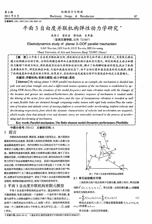
单 的 能 动 : f1T d: 6 元 势 和 能 ) D 1 “ ( : 21 “
£ J q Q导 m’ ) d= 6 = s
式 中 : — 力应变关系矩阵 ;一面积密度 ; , —单元刚度 位 q k m
3机构动态特征
31机构振 动方程 的求解 及弹性 位移 .
【 b ta t B kn pa a - O aa e m c a i a a xm l, e c ai i dv e t A s c 】 yt ig l r D F r l l eh s s nea pe t h s s ii di o r a n 3 p l n m h m n m d n e p l uiad l etag n , da ie n am t n q ao t cai s b se - o n pa i l ui a d r tl oo ut n f h m h s ie alhd y p e t n n r e t n f e i i e i o e n e n ms t i ba pyn E er.hnte i aoso tem d fe unyadm i vbai oewt tecags l gF M t oyTe t t n h oa rqec an ir o m d i h e i h h su i f l n t n hh n f o tel ai dg s r ae aaye .utem r , ed nmi e o eo c a i tde n r h o t o a et er l zdF r r et y a c rs n m hn m i s i u d c nn u n ho h s ps f e s s u d e te r i t cv fr di ra oc, d h p nt t eu v r i va da w l h in o h ate o e e ifr a e ye fi a a os i ao i r e e e d v gf e i ca nt n en t t o s n n bt ns e l s l 珊 ma f xbel k r ot ndtruhcm ai ai t nwt gdbd t nTu h ai il il i s e ba e og o p n r lym i i r i o moi .h tevr - n e n a i h r g e to o hi y o s a t no l ai datueerro m vn lfr sace ne clr i , n om vlcyad i oto a i d r s o f c nn t t o oi aomir e hdudr eea n u ir eoi f gpt se r c a t g f tn d c l a n se t e ,o hc ed nmi c aatr t so vlc ya daclr i r q i d eeet gr p ci l f m w i t a c h c ei i eoi ceea o aea u e , ri e vy r hh y r sc f tn t n c r w i sl hwta tueerr ddn i ses r nte l icesdi e r eso clr hc r tso t a i d r ya c ts e oi a y nrae t o s f a ee- h eu s h tt oa n m r a cb nh p c c t n eeea n o eh s aigaddclr i m cai . n t gf n m
一种3自由度并联抛磨机械臂的运动学分析

2024年第48卷第4期Journal of Mechanical Transmission一种3自由度并联抛磨机械臂的运动学分析包新棉1王学雷2张伟涛1王禄1赵栋杰1(1 聊城大学机械与汽车工程学院,山东聊城252000)(2 北京电子科技职业学院汽车工程学院,北京100176)摘要针对百叶窗叶片的仿形抛磨要求,研究了一种可为末端执行器提供X向、Y向的移动和Z 向转动的3自由度并联机械臂。
为了验证机械臂的运动学性能,首先,描述了其机构特征,并基于螺旋理论进行了机构自由度分析;其次,基于闭环矢量法构建了机构运动学方程,对其进行了位置正、逆解分析,并通过具体算例对分析结果进行了初步验证;最后,构建了机构的数值仿真模型和虚拟样机模型,进行了位置、速度的逆运动学仿真分析。
仿真结果表明,两种模型的分析结果一致,逆解理论分析结果可信;机械臂各支链可协调运动,运动过程平稳,位移、速度曲线平滑、无突变,可为后续机械臂的尺寸优化和运动控制提供依据。
关键词并联机械臂螺旋理论运动学虚拟样机Kinematic Analysis of a 3-DOF Parallel Polishing ManipulatorBao Xinmian1Wang Xuelei2Zhang Weitao1Wang Lu1Zhao Dongjie1(1 School of Mechanical & Automotive Engineering, Liaocheng University, Liaocheng 252000, China)(2 School of Automotive Engineering, Beijing Polytechnic, Beijing 100176, China)Abstract A 3-DOF parallel manipulator with X, Y movement and Z rotation for the end-effector is stud⁃ied in order to meet the requirements of copying and polishing of louver blades. In order to verify the kinematic performance of the manipulator, firstly, the mechanism characteristics are described, and the degree of freedom of the mechanism is analyzed based on the spiral theory. Secondly, the kinematics equations of the mechanism are constructed based on the closed-loop vector method, the forward and inverse position solutions are analyzed, and the analysis results are preliminarily verified by concrete examples. Finally, the numerical simulation model and virtual prototype model of the mechanism are constructed, and the inverse kinematics simulation analysis of the position and velocity is carried out. The simulation results show that the analysis results of the two models are consistent, and the result of inverse solution is reliable. The arm chain can coordinate the movement, the movement process is smooth, and the displacement and velocity curves are smooth and without mutation, and can provide a basis for the size optimization and motion control of the manipulator.Key words Parallel manipulator Spiral theory Kinematics Virtual prototype0 引言百叶窗具有良好的通风换气、防热降温功能,广泛应用于民居、大型厂房等场所。
3自由度工业机器人(外文翻译)
动态优化的一种新型高速,高精度的三自由度机械手①彭兰(兰朋)②,鲁南立,孙立宁,丁倾永(机械电子工程学院,哈尔滨理工学院,哈尔滨 150001,中国)( Robotics Institute。
Harbin Institute of Technology,Harbin 150001,P。
R。
China)摘要介绍了一种动态优化三自由度高速、高精度相结合,直接驱动臂平面并联机构和线性驱动器,它可以提高其刚度进行了动力学分析软件ADAMS仿真模拟环境中,进行仿真模拟实验.设计调查是由参数分析工具完成处理的,分析了设计变量的近似的敏感性,包括影响参数的每道光束截面和相对位置的线性驱动器上的性能.在适当的方式下,模型可以获得一个轻量级动态优化和小变形的参数。
一个平面并联机构不同截面是用来改进机械手的.结果发生明显的改进后的系统动力学仿真分析和另一个未精制一个几乎是几乎相等.但刚度的改进的质量大大降低,说明这种方法更为有效的。
关键词: 机械手、 ADAMS、优化、动力学仿真0 简介并联结构机械手(PKM)是一个很有前途的机器操作和装配的电子装置,因为他们有一些明显的优势,例如:串行机械手的高负荷承载能力,良好的动态性能和精确定位的优点等. 一种新型复合3一DOF臂的优点和串行机械手,也是并联机构为研究对象,三自由度并联机器人是少自由度并联机器人的重要类型。
三自由度并联机器人由于结构简单,控制相对容易,价格便宜等优点,具有很好的应用前景。
但由于它们比六自由度并联机器人更复杂的运动特性,增加了这类机构型综合的难度,因此对三自由度并联机器人进行型综合具有理论意义和实际价值。
本文利用螺旋理论对三自由度并联机器人进行型综合,以总结某些规律,进一步丰富型综合理论,并为新机型的选型提供理论依据,以下对其进行阐述。
如图-1所示机械手组成的平面并联机构(PPM)包括平行四边形结构和线性驱动器安装在PPM.两直接驱动电机c整合交流电高分辨率编码器的一部分作为驱动平面并联机械装置.线型致动器驱动的声音线圈发动机.这被认为是理想的驱动短行程的一部分.作为一个非换直接驱动类,音圈电机可以提供高位置敏感和完美的力量与中风的角色,高精密线性编码作为回馈部分保证在垂直方向可重复性。
三自由度可调并联机构的位置与运动学分析

P o s i t i o n a l a n d Ki n e ma t i c s A n a l y s i s o f A d j u s t a b l e T h r e e - D OF P a r a l l e l Me c h a is n m
YAO Xi a n g, L I N Gu a n g — c h u n, D0U Yi — l i n g
文章编号 : 1 0 0 1 — 2 2 6 5 ( 2 0 1 5 ) 0 3— 0 0 5 9— 0 3
D O I : 1 0 . 1 3 4 6 2 / j . c n k i . m m t a m t . 2 0 1 5 . 0 3 . 0 1 6
三 自由度 可调 并 联 机 构 的位 置 与运 动 学 分 析
姚 翔, 林 光春 , 豆依 玲
( 四川大 学 制造科 学与工程 学院 , 成 都 6 1 0 0 6 5 ) 摘要 : 针 对 一种 三 自由度 的球 面并联 平 台机 构 , 基 于符 号. 数 字方 法 , 建 立 了机 构 的位 置 正 解数 学模 型, 在此 基础 上推 导 出了末 端执行 器( 动平 台) 球 铰质 心 点的速 度 、 加 速度 的 正反 解数 学模 型 , 研究了 机 构 的运动 学特 性 。利 用 Ma t l a b符 号运 算对模 型进 行 实例 求解 , 验 证 了该 方法 的正确 性 。研 究 了调 节驱动杆 杆 长和速 度 时动 平 台位 置 的 变化 规律 , 对 该机 构 的动力 学研 究提 供 了基 础 。 关 键词 : 三 自由度 ; 可调 并联 机构 ; 位 置分析 中图分 类号 : T H1 1 2; T G 6 5 9 文 献标 识码 : A
【机械专业中文翻译】平行结构两个或三个自由度
目录 1 0 0 7—0 2 1 4 1 7 1 9 P P 1 0 5’、—1 1 2V o l u m e 8,N u m b e t 1,F e b r u a r y 2 0 0 3平行结构两个或三个自由度刘辛军、汪劲松、李铁民、段广洪。
北京清华大学工程学院。
1000841摘要平行机器人在机器人工业界已广泛的研究,服务于各工业的工作领域,并成为设计上综合发展体系的,越复杂的平行机构将带来越多的研究兴趣,并行手法少于6级的自由度,几个平行的机制与各种数量和类型。
自由度本文描述,可以用在平行机器,运动模拟器和工业机器人。
关键词平行机器人,平行,运动学机械自由度机器人引言机械系统,从而使刚体转动方面中扮演非常重要的角色,无数的机构,可迁入各种平移或旋转方向的一个回顾程度。
自由度,为僵化的身体不能超过6 ,举例来说,三个翻译议案沿相互或轴线和三个转动提出的关于这些机器人包括系统控制若干程度的结束效应。
过去几年来,经历了重要的发展情况,在一辈人使用工业机器人,主要是由于其机械结构的最常见的机器人,是没有很好地适应某些类型的架构也因此,最近已开发为工业用途,其中包括平行机器人。
一个平行的机械臂,这是一个闭环几个四肢或有多少手杆,等于多少个自由度,如每肢体是由一个致动器和所有驱动器可安装在或接近固定这个原因,平行升有时华航主导平台外部负载可以共享的,由作动器,平行机构往往有一个大的承载手法总是作为具有非常好的表现,无论在精度,刚度并有能力操控大型已用于大批应用范围从飞行模拟器,并正成为越来越受欢迎的,在机床行业。
该设计平行机器人,可以追溯到1947年,当的基本原则,机制与闭环系统的运动学结构,以控制位置和方向的移动平台,以测试轮胎磨损和建起了原型在1955年(图1 )元素是一个六角形的平台,其顶点都连接到三通由球和插座,然后的另一端连接被重视该基地由然后第九线性传动改造总升油墨长度。
斯图尔特设计了一个平台机器人作为模拟器于1965年(图二),其中感人元素是一个平台,其顶点都连接球及插座,然后支持每个机制构成的两个千斤顶,放置提出了系统的研究运动学结构的平行机器人与平面三是保障计划平行升手法作为一个典型的的例子。
- 1、下载文档前请自行甄别文档内容的完整性,平台不提供额外的编辑、内容补充、找答案等附加服务。
- 2、"仅部分预览"的文档,不可在线预览部分如存在完整性等问题,可反馈申请退款(可完整预览的文档不适用该条件!)。
- 3、如文档侵犯您的权益,请联系客服反馈,我们会尽快为您处理(人工客服工作时间:9:00-18:30)。
3自由度并联机床的运动学和动力学研究
摘要:中国东北大学已经研制出一种用于钢坯研磨的新型3自由度并联机床。
它具有结构简单,刚度大的优点,更高的力量重量比,较大的工作空间,简单的运动学方程,没有运动的奇异位姿。
在使用相应刀具情况下该机器人可用于磨削,研磨,抛光等加工过程。
在本文中,介绍了简单的机器人的结构和自由度,运动学和工作空间,精度分析,静态和动态的分析及其相关参数。
关键词:并联机床;运动学;动力学;3自由度
1.前言
与传统机床相比,并联机床具有更高的精度,高刚度的优点,和更高的刚度质量比,所以近些年它得到了行业和机构大量的研究和评估。
由美国Giddings & Lewis公司研制的“六足虫”并联机床被认为是21世纪机床领域中的革命性理念。
然而这个Stewart平台存在运动耦合的缺点,并且具有复杂的运动学和构件要求十分严格。
这类少于六自由度并联机床在行业和机构也因此受到越来越多的关注。
意大利Comau研制出了一种命名为Tricept的四条腿的的三自由度并联机床。
东北大学已经开发出了一种新型三自由度的三腿平行磨削机床(图1)。
与“六足虫”并联机床相比,此三腿平行磨削并联机床具有以下优点:(1)结构简单且具有更大工作空间;(2)动力学方程简单便于控制操作;(3)在工作空间没有运动耦合状态。
图1
2.并联机床
2.1 3自由度系统的布局
该三自由度并联机构由一个移动平台,基础平台,一个平行的联动和三条腿的连接两个平台。
中间腿支链控制的移动平台的三个自由,如图2所示。
移动平台的转换是由平行连杆机构控制。
图2
2.2 运动学和工作空间
移动平台平行于基础平台,一个坐标系统(O- X,Y,Z)选择如图2所示,这种机制的逆向运动学正解方程可以表示为:
123l l l ===其中w=a-b
,2m = ,n=w/2 ,a 和分别表示基础平台的两侧的长度和等边三角形状的移动平台的长度。
该机构的位置正解方程可表示为:
2222
222132X l l w Y w Z =
-+=
=
从公式1和2可知系统在整个工作空间无奇异位姿和运动耦合。
其工作空间的形状如图3所示:它是一个三角曲面的金字塔。
其最大断面和深度均大于正常工作情况的数值。
这对于如磨削、抛光、焊接等加工形式都是非常适合的。
图3
3.控制系统
研磨操作应进行连续路径控制,
控制连续路径符合雅可比矩阵之间的
关系。
p V (动平台的速度)和l V (腿的延伸率)可以表示为p l V JV = 其中:312
1[
],[]T
T
p dl dl dl dX dY dZ V V dt
dt
dt dt
dt
dt
== 该雅克比矩阵计算如下:
3
1
222222222222[
]l l J w
w
-=
如果P ∆和 θ∆分别代表每分钟位置的变化和动平台的旋转角度,并且K 描述角度对三条腿的线位移,如下方程可以确立:
1kJ P θ∆=∆
根据上述所提到的,连续的路径控制单元的设计已经完成。
三条腿的控制是用C 语言编制的软件程序来实现的。
它具有良好的适应性和可移植性。
机器人示意图如图4所示。
图
4
4. 静力学和动力学分析 4.1 静力学
假设三脚并联机床载荷(如磨削载荷)矩阵是F ,驱动臂力矩阵是1F (图5),则有:
[]X
Y
Z F F F F =和11
2
3[]F F F F =
且根据虚位移理论,正解矩阵为:1T F J F =-,静力学逆解为11()T F J F -=-从上面的静力学分析也可以看出转矩是由平动机构承担的。
此外切削力是由三个环节的拉力承担。
这个机制在力学结构上是合理的。
图5
4.2.动力学
根据朗格朗日方程,每条腿的轴驱动力i F 为:
(),1,2,3i i i i
d K K P
F i dt q q q ∂∂∂=
-+=∂∂∂ 其中K 是动能,P 的潜在能量,i q 是关节的广义坐标。
用于驱动腿如图6所示,忽略关节摩擦力和平移运动机理,可以得出以下的动力学
方程:
3
33
2
2
1111
()(2())()(()sin cos )i i P P P ci ci i ci i
ci ci ci i i ci i i i i m m m m F M X Y Z m l l l l m m l Mg mg l m m θθθθθ===--=+++++--+++∑∑∑
其中ci l 是固定端到质心的距离,m 是连杆i 的质量,m 是较低的联络线振荡环节i 的质量,M 是动平台质量,1θ是连杆i 和底平台夹角。
图6
5.结论
这种新型并联机床是非常方便实用。
由于机构的独特运动转换方式,其运动学是简单的,且无奇异位形和运动。
因此,该机构易于进行实时控制。
如果有其他的刀具,这个机器人还可以改装发展其他机床和机器人进行应用。