GT系列运动控制器 用户手册
美丽手表Amazfit GTR用户手册说明书
Amazfit GTR User ManualContentOperating Instructions and Functions Navigation (2)Basic Operations (2)Functions Navigation (2)Watch Wearing and Charging (4)Use of Functions (5)Device Pairing and Unpairing (5)Control Shortcut Menu (7)Flashlight (7)Brightness adjustment (8)DND mode (8)Battery saver mode (9)Lock screen (10)Replace the Watch Face (11)Status (11)Heart Rate (12)Workout (13)Workout Record (14)Weather (15)Music (16)Notifications (17)Alarm (18)Event Reminder (20)Timer (22)Count Down (23)Find Device (24)Compass/Air Pressure/Altitude (25)Settings (27)Workout Function (29)Workout Positioning (30)During Workouts (31)Swimming (32)Workout Reminder (33)Workout Pause and End (33)Workout Settings (34)Operating Instructions and Functions NavigationAmazfit GTR features one AMOLED touch screen and two physical buttons.Basic OperationsSlide left and right or up and down: You can switch between different function pages.Tap and exit: You can tap to enter a specific function page and also operate the tap tips on that page. You can slide right to quickly return to the upper-level menu after tapping to enter a certain function page.Button on the upper right:①Short press to light up the screen.②Short press the watch face page to close the screen.③Short press other pages to quickly return to the watch face.④Long press for 10s to shut down.Button on the bottom right:①Short press to light up the screen.②Short press the watch face page to quickly enter the workout list. (This function can be customized and used to short press to quickly start other functions)You can long press either of the two buttons above to exit the battery saver mode, suspend the workout, and close the alarm alert.Functions NavigationPull the watch face down: You can then enter the shortcut control menu, which allows you to quickly open the flashlight, set brightness, control the DND mode, enter the battery saver mode, and lock the screen.Slide the watch face left and right: You can then quickly enter Status, Heart rate,Slide the watch face up: You can then enter the function list.Watch Wearing and ChargingDaily wearing: During daily use, it is recommended to wear the watch with a moderate tightness at a distance two fingers far from your wrist to ensure that the optical heart rate monitor works properly. Wearing during workouts: During workouts, it is recommended to wear the watch comfortably and ensure a tight fit without slipping. Being too tight or too loose may cause the inaccuracy of detected workout data, so avoid doing this.Charging•The watch charger's USB port needs to be plugged into the USB-supported device, such as socket, PC, power bank.•When placing the watch into the power socket, it's required to keep the watch in a proper direction and position. Be sure that the metal contacts on the back of the watch are closely connected to the charging base.•The screen will display the charging reminder when the watch is placed properly.Use of FunctionsDownload the Amazfit App via the mobile phone before using Amazfit GTR. You cannot use the entire watch functions nor save and upload watch data to your personal cloud account until the watch is paired by using the Amazfit App.Device Pairing and Unpairing Download the Amazfit App from Google Play Store or App Store and register an account or log in.Open the Amazfit App and choose "Profile – My devices – Watch – Amazfit GTR" to search the device nearby.Please tap the check-mark when it shows a pairing request on the watch.If a device can be paired by scanning a QR code, with the Amazfit App on, you can directly pair the device by scanning the QR code on your watch.After paired, the watch usually needs to be upgraded. Wait for upgrading with patience. With the mobile network and Bluetooth on, you also need to keep the watch close to the mobile phone, so as to ensure a successful upgrade.After the watch is paired and upgraded, its functions are available. Meanwhile, the Amazfit App allows for the watch function-specific operations and settings.To unpair the watch, open the Amazfit App, tap "Profile – My devices – Amazfit GTR" and then swipe up and tap the "Unpair" button.Control Shortcut MenuPulling down on the watch face page can quickly open the control shortcut menu page.FlashlightTapping the flashlight icon can open the flashlight function. The white background on the watch screen helps light up a small area at night. You can close the enabled flashlight function by slidingright or pressing the button on the upper right.Brightness adjustmentTapping on the brightness adjustment button can go to the brightness adjustment settings.Auto brightness: The watch will automatically adjust the screen brightness upon ambient light. Manual brightness: You can tailor the screen brightness as you wish.DND modeEnable DND: With the DND mode enabled, the watch will not vibrate when receiving any message pushed by the mobile phone.Time DND: You can tailor the time period during which the DND mode changes from automatically enabled to disabled.Smart DND: After you fall asleep with the watch, the watch will automatically enable the DND mode.Disable DND: The DND mode is disabled, so the watch will vibrate when receiving notifications.Battery saver modeThe battery saver mode can minimize the power consumption of the watch and improve its endurance. With the battery saver mode on, the watch can only record steps and sleep time, with other functions disabled.To exit the battery saver mode, long press any button on the watch.Lock screenWith the lock screen function on, you can unlock the watch to enter the watch face page only by using the watch button. This can prevent any error caused by mistouch. To close the lock screen function, tap the lock screen button again to close this function.Replace the Watch FaceTo replace the watch face on the watch: Long press the watch face page for 2s, or go to "Settings –Watch face settings", slide left and right to scan the watch face, and tap one to complete replacement. To replace the watch face on the App: Tap "Profile –Amazfit GTR –Watch face settings" to download more watch faces on the Watch Face Store.StatusSliding left on the watch face page can enable you to enter the status page which displays the current steps and goal completed. Tapping the status entry can enable you to enter the details page whichshows you the steps, distance, calories and idle data.You can also enter the details page by sliding up on the watch face page and choosing "Status".Heart RateSliding left on the watch face can enable you to enter the heart rate page, and then the watch automatically starts to measure the heart rate. During measurement, it is required to properly wear the watch and keep the back of the watch fairly close to your skin until the watch can measure a stable heart rate.To enable the all-day measure function, open the Amazfit App, go to "Profile – Amazfit GTR –Heart rate detection", and choose to enable automatic heart rate detection.Notes: With the all-day measure function on, the watch will measure the heart rate at regular time. Sliding right on the watch face can make the last heart rate value visible. You can enter the all-day heart rate details page by tapping it.WorkoutAmazfit GTR supports twelve workout types: Outdoor running, Walking, Outdoor cycling, Treadmill, Indoor cycling, Pool swim, Open water swim, Elliptical trainer, Climb, Trail run, Skiing, and Exercise. See the "Workout" section for more details about the functions of different workout types.Workout RecordThe workout data on the watch will be stored in workout records, which are shown from the latest to the earliest. Tapping a specific workout record will make the workout details visible. The visible details vary in workout type.The workout record not uploaded to the App will be marked with a little red dot before it. Open the App to synchronize data timely to avoid the loss of workout records.To delete a workout record on the watch, tap to enter the workout record details page, slide up to the bottom of the page, and then tap the delete button.WeatherTapping the weather function can give you access to the current weather conditions and the weather forecast. If weather data are invisible, you should open the App and connect the device to update the data.MusicWith the Bluetooth, the watch can suspend or play the music on the mobile music player, switch between songs, and adjust the volume.• Open the mobile music player first, and then enable the music function on the watch.• If you are using an iOS device, you need to pair and connect the watch with the Amazfit App. • If you are using an Android device, you need to connect the watch with the Amazfit App andalso enable the notification reading permission on the App.Notes: The compatibility of the Android mobile phone system and the openness of different music players may to a certain extent affect the music control function of the watch.NotificationsEnable notificationsDuring use, you need to enable the corresponding "App alerts" on the App, and keep the watch and the mobile phone connected. You can also enable the incoming SMS and incoming call alerts as you wish.•If you are using an iOS device, you need to pair and connect the watch with the Amazfit App. •If you are using an Android device, you need to keep the App running in the background or include the App into the self-starting whitelist, so as to ensure the mobile phone can send the alert to the watch.View notifications1.In the case of an incoming notification, the watch will automatically light up the screen anddisplay the content.2.You can view the unread notification in the notification list and tap any notification to enter thenotification details page.Delete notifications•The read notification on the watch or the mobile phone will be automatically deleted from the notification list on the watch.•To manually delete the notification on the watch, slide left on the notification to be deleted and tap the delete button.AlarmAmazfit GTR supports creating and managing the alarm on the watch. You can also create a watch alarm on the Amazfit App.Tapping the create button on the watch alarm function page can enable you to set the alarm time andcycle. After saved, the alarm can be opened and closed in the alarm list.To create an alarm via the Amazfit App, go to "Profile – Amazfit GTR – Watch alarm" and add an alarm upon the tips on the page.Alarm alertIn the case of a watch alarm alert, you can choose to close it or remind you later.To close the alarm, long press any button for 2s within the duration of the alarm alert.To make a delayed alert, you can, within the duration of the alarm alert, tap the "Z" button at the bottom. Then, the alarm will remind you 10min later.Event ReminderYou need to create and manage the event reminder via the Amazfit App. The watch will display your to-do list and vibrate to remind you in the set time.Open the Amazfit App, go to "Profile – Amazfit GTR –Event reminder", and create the event reminder upon the tips on the page.An alert will pop up on the watch when the time set for the event arrives. Tap the "×" button at the bottom to close the alert.The watch supports modifying and deleting the event reminder.To modify the event reminder, tap the right arrow on the event reminder list page to modify the event reminder date and time.To delete the event reminder, slide right on the event to be deleted and tap the trash icon to delete it.TimerThe timer on the watch supports one hundredth of a second. To enable the timer, pull up the app list on the watch face and choose the timer app.•Tapping the start button can activate the timer to time it right away.•During timing, you can also count the number of times by tapping the button on the bottom left on the watch screen (up to 99 times of such operation),•and suspend the current timer by tapping the button on the bottom right on the watch screen. •When the timer pauses, you can reset it by tapping the button on the bottom left on the watch screen, and resume timing by tapping the button on the bottom right on the watch screen.Count DownTo enable the count down, pull up the app list on the watch face and choose the count down app. By default, the watch supports the shortcut count down of 1min, 3min, 5min, 10min, 15min, 20min, 30min, and 60min. You can enable the count down function right away by tapping it.A custom count down function is available, which ranges from 1min to 23h and 59min.You can suspend, resume or stop the count down function anytime when it operates. When time's up, the watch will vibrate to remind you. You can close the count down function by tapping the "×" button at the bottom.Find DeviceAmazfit GTR supports finding the device via the Bluetooth. To enable this function, slide up the app list on the watch face page and tap the find device function.•To activate the find device function, you need to keep the Amazfit App running and ensure the watch is connected to the mobile phone. Otherwise the function is not available.•On the find page, the watch will automatically find the device. If no device is found after 60s,a failure prompt will display and then you can try again.When found, the mobile phone will beep. You can close the ring on the mobile phone by tapping the tip button on the watch. Meanwhile, the mobile phone will produce a message on the notification bar. Tapping the message can draw back the Amazfit App and close the ring on the mobile phone.Notes: If you wish to use the find device function anytime, you can include the Amazfit App into the built-in self-starting whitelist and keep it running in the background. In addition, the watch is required to be connected to the mobile phone, otherwise it is unable to find the mobile phone.Compass/Air Pressure/AltitudeAmazfit GTR supports the compass function. When the compass page opens, the watch automatically detects the current orientation and degree. If needed, you can wear the watch and calibrate the compass by filling out that circle with figure 8 movements in the air, until the watch vibrates. Then the compass function can be reused.Sliding up on the compass page can enable you to enter the atmospheric pressure page. The barometer on the watch displays the current air pressure in real time.Sliding up on the air pressure page can enable you to enter the altitude page. The altitude requires double calibration of watch barometer and GPS. If you want more accurate altitude data, try to get the satellite positioning in an open area as soon as possible.SettingsThe watch settings page includes some watch settings and built-in control functions.Watch face settings: You can quickly switch between watch faces.Screen-on duration: You can control the screen-on duration of the watch for 8s (by default) to 15s (max).Quick start: You can short press the button on the bottom right to quickly start one watch function (by default, workout list).System: It supports viewing the firmware version and regulatory information, and controlling the actions of closing and rebooting the watch and performing the factory reset.Workout FunctionAmazfit GTR supports twelve workout types: Outdoor running, Walking, Outdoor cycling, Treadmill, Indoor cycling, Pool swim, Open water swim, Elliptical trainer, Climb, Trail run, Skiing, and Exercise. And the workout types like Outdoor running, Walking, Outdoor cycling, Open water swim, Climb, Trail run, and Skiing support recording GPS-enabled workout tracks.There are two approaches to enabling the workout function on the watch:•If the workout list is set for quick start, then you can quickly enter the workout list by short pressing the button on the bottom right on the watch face page. By default, the last workout type displays.•Sliding up on the watch face page and choosing "Workout" can enable you to enter the workout list page and choose the workout you want to start.Workout PositioningIf you choose to start Outdoor running, you'd better go to the open area before workouts, which is conducive to rapid GPS positioning.If it takes a long time to process positioning, it may be because the buildings nearby block satellite signals, or because the watch is disconnected to the App for a long time, causing the AGPS to be not upgraded. You can open the Amazfit App, connect it to the watch, and try again after the AGPS is updated.It is recommended to ensure GPS positioning is processed successfully before the outdoor workout. If you start the workout during positioning, the workout track cannot be recorded and the recorded workout data will not be accurate.After GPS positioning is processed successfully, the "GO" icon will be lit up and you can tap it to start the workout.During WorkoutsDuring workouts, the watch will display the current workout data in real time, such as time, distance, pace/speed, and heart rate. After the watch screen goes off, the screen can be lit up again by lifting the wrist or touching the screen.Sliding right during workouts can enable you to view the time, date, and watch power.SwimmingWith the swimming workout enabled, the watch will automatically lock the screen to avoid water drops interfering with the screen display during the workout. To unlock the screen, you can short press any button on the watch, and the screen will be locked again after the watch screen goes off.Workout ReminderThe workout reminder on the watch varies in workout type. For the workout types Running, Cycling, and Walking, the alert will be vibrated once per kilometer by default. You can also set the alerts for other workout types before workouts. See the "Workout Settings" section for more details.Workout Pause and EndWith the auto pause function on, the watch will automatically pause when the workout end is detected. When the workout resumes, the watch will automatically end the pause status and resume recording the workout performance.Tapping any button during a workout can suspend the workout.Tapping the right button can cancel the pause and resume the workout.Tapping the left button can end the current workout and save the workout performance. Workout SettingsBefore workouts, you can set some relevant functions.The workout goal supports three types: mileage, duration, and calories. When the set goal is achieved, the watch will vibrate to remind you.The workout reminder supports five types: distance, pace, safe heart rate, heart rate zone, and pace With a reminder set, the watch will vibrate to remind you as long as the set value is reached during workouts.With the auto pause on, the watch will automatically detect the workout status. When the workout is stopped, the watch will automatically suspend the current exercise. And the watch will re-record the data when the workout is resumed.The real-time diagram supports demonstrating the real-time heart rate and pace. With the real-time diagram on, a curve is drawn for the fluctuations of the heart rate or pace during workouts.Notes: Some workout types don't support the above four settings. The settings might slightly vary in workout type.。
基于C#语言的GTS控制卡入门手册(1)
图 6 端子板电源连接图 3)端子板与驱动器连接 一般情况下,伺服驱动器的 C1 接口用屏蔽电缆连接到轴通道 CN1~CN8。
(a)包装盒标签
(b)板卡上的标签
(c)端子板标签 图 1 运动控制器的型号 请戴上配备的防静电手套从产品包装箱取出运动控制卡,然后插入到计算机 机箱中 PCI 插槽,在这之前请确认计算机关闭电源。插好之后,用螺丝将 GTS 卡 转接板固定在机箱上。
1.2 安装运动控制器驱动程序
1)GTS 卡安装好之后,启动计算机,点击“我的电脑”—“属性”—“设
图 4 驱动安装成功提示
1.3 硬件之间的连接
1)运动控制器与段子板的连接
关闭计算机电源,取出产品附带的屏蔽电缆(4 轴卡 1 条,8 轴卡 2 条)。以 4 轴卡为例,屏蔽电缆一端连接控制卡,一端连接端子板(注意:运动控制卡接 口、屏蔽电缆线和端子板都带有标识“CN17”,需要更换时要避免带电插拔), 如图 5 所示连接。
第 1 章 控制卡和端子板型号识别以及硬件连接 1.1 认识运动控制卡和硬件安装
运动控制器包含两个部件:运动控制卡和端子板。从包装盒侧面标签处可以 知道 GTS 卡和端子板的型号,还可以通过 GTS 卡和端子板上的标签得知型号。 如 图 1 所 示VB-LASER ; 端 子 板 型 号 为 GT2-400-ACC2-VB-G-A。
图 29
在 private void button5_click(object sender,EventArgs e) { } 中输入以下代码,如图 30
固高GT2用户手册
地 址:深圳市高新技术产业园南区深港产学研基地西座 二层 W211 室
电 话:0755-26970823 26970819 26970824 传 真:0755-26970821 电子邮件:support@ 网 址:
务必将此手册交给用户 z 非常感谢您选购 GT 系z 请将此手册妥善保存,以备随时查阅。
版权申明
版权声明
固高科技有限公司 保留所有权力
固高科技有限公司(以下简称固高科技)保留在不事先通知的情况下,修改本手册中的 产品和产品规格等文件的权力。
您也可以通过电话(0755-26970839)咨询关于公司和产品的更多信息。
技术支持和售后服务
您可以通过以下途径获得我们的技术支持和售后服务: ♦ 电子邮件: support@; ♦ 电话: (0755) 26970835 ♦ 发函至:深圳市高新技术产业园南区园深港产学研基地西座二楼 W211 室 固高科技(深圳)有限公司 邮编:518057
固高科技(香港)有限公司
地 址:香港九龙清水湾香港科技大学新翼楼 3639 室 电 话:(852) 2358-1033 传 真:(852) 2358-4931 电子邮件:info@ 网 址:/
GT 系列运动控制器 用户手册
附录A 技术参数 -----------------------------------------------------------------------------------------------------------A-1
附录B 位置、速度、加速度设置---------------------------------------------------------------------------------------B-1 B.1 位置设置 ............................................................................................................................................... B-1 B.2 速度设置 ............................................................................................................................................... B-1 B.3 加速度设置 ........................................................................................................................................... B-2
Panasonic GT 32 技术手册
否则会造成电池和电子部品等的破裂。
注意
当发生错误操作时,会出现使用者重伤或物品损害的危险状态
●为防止异常发热和冒烟,使用时请相对于本产品的保证特性、性能值留有一定的余量。 ●请勿分解、改造。否则会引起异常发热和冒烟。 ●通电过程中请勿触摸端子。否则会引起触电。 ●请在外部构成紧急停止、联锁电路。 ●请正确连接电线和连接器。以免因接触不良而引起异常发热和冒烟。 ●请勿将液体、可燃物、金属等异物放入产品内部。否则会引起异常发热和冒烟。 ●请勿在接通电源的状态下进行施工(连接、拆卸等)。否则会引起触电。 ●触摸开关的操作力应在产品规格值以下。用力过度时会造成破损、受伤。 ●本触摸开关为模拟电阻膜方式。请勿在屏幕上同时按下2个或2个以上点。
前言
承蒙购买可编程智能操作面板 GT 系列,在此向您表示诚挚的谢意。 本手册对规格、与 PLC 的连接方法、环境设置、维护、GTWIN 的安装方 法进行说明。 请在充分理解手册内容的基础上使用。
目录
使用前的注意事项
i
第 1 章 规格 ................................................................................................................................... 1-1 1.1 GT32 的规格 ......................................................................................................................................... 1-2 1.1.1 一般规格 ........................................................................................................................................ 1-2 1.1.2 显示部规格..................................................................................................................................... 1-2 1.1.3 触摸开关规格 ................................................................................................................................. 1-3 1.1.4 功能规格 ........................................................................................................................................ 1-3 1.1.5 存储器规格..................................................................................................................................... 1-4 1.1.6 通信接口规格 ................................................................................................................................. 1-4 1.1.7 外部存储器规格 ............................................................................................................................. 1-5 1.1.8 声音输出规格(仅限GT32T1) ......................................................................................................... 1-5 1.2 各部位的名称和功能............................................................................................................................. 1-6 1.2.1 GT32 .............................................................................................................................................. 1-6 1.3 各端口的说明........................................................................................................................................ 1-8 1.3.1 COM.端口....................................................................................................................................... 1-8 1.3.2 USB端口......................................................................................................................................... 1-9 1.3.3 Ethernet端口(GT32T1)................................................................................................................ 1-12 1.4 外形尺寸图 ......................................................................................................................................... 1-15 1.4.1 GT32 ............................................................................................................................................ 1-15
GTS功能及行业应用介绍
八轴控制器
8轴电机控制(包括脉冲、模拟量、限位、原点 等) 1路辅助编码器 16路通用数字量输入 16路通用数字量输出
四轴端子板
4轴电机控制 8路AD输入 2路辅助编码器
16路通用数字量输入
16路通用数字量输出
运动模式
点位运动 JOG 电子齿轮 PT PVT 电子凸轮(FOLLOW) 插补
支持多线程编程
在Windows操作系统下支持多线程编程 支持单卡模式下的多线程编程
支持多卡模式下的多线程编程(需要特殊的动 态链接库)
初始化配置多样化(与标准卡区别)
ห้องสมุดไป่ตู้
配置工具+配置文件 初始化配置指令:GT_CtrlMode()、 GT_StepDir() …………
位置比较输出功能
能够跟随任意轴的规划位置、编码器位置 能够设置跟随方向、启动跟随条件、循环 跟随次数 提供2个电子凸轮数据表,可以在运动状态 下进行切换
插补运动
支持两个坐标系同时进行插补运动 支持直线和平面圆弧插补,描述方式符合G代码标准 插补缓存区段数多达4096段 支持缓存区暂停、恢复,暂停后可以进行其他运动 具有前瞻预处理功能,前瞻缓存区大小由用户指定 支持插补缓存区内的延时和数字量输出操作 缓存区内支持改变加速度、目标速度 可以支持当量不一致的插补运动 刀向跟随
钻孔机视频 固晶机视频
应用举例2——流水线
流水线运动(区别于异步电机控制)
JOG运动
独立设置加速度和减速度,实现非对称加 减速 能够设置S曲线加减速,实现平滑运动 能够在运动状态下更新目标速度
HDL-GT>R系列操作菜单日中文对照表

打开用户用的设定页面打开管理者用的设定页面打开在线的产品手册请选择以上的菜单管理员密码输入不知道管理员密码的情况下,请参照CD-ROM内操作手册查看信息菜单栏退出系统信息网络信息磁盘组信息日志信息2-1,2-2,2-3,2-4,鼠标双击此硬盘组硬盘组运行正常表示项目的指定管理者日志停止管理者日志记录成功网络设定共享管理磁盘管理备份管理系统管理管理员密码变更Email 通知通过音乐查找放置GT 的位置3-1.3-2.3-3.3-4.3-5.3-6.3-7.3-8.9共享服务设定MS 网络设定TCP/IP 设定3-1-1.3-1-2.3-1-3.10有效服务选择3-1-2.MSネットワーク設定(MS网络设定)注意:在使用域的情况下,请将工作组切换到在进入域后,域用户名和域用户组以是共有,若要切换到工作,组状态,以前所保存的共有数据将被消除。
还有,在进入不同的域时,不能使用以前的域用户和域工作组。
输入共享文件夹管理用户管理组群管理3-2-1.3-2-2.3-2-3.13添加的共享文件夹注释服务添加用户密码变更一次建立多个新用户在LANDISK上组群,磁盘组操作磁盘组设定检测修复磁盘节能模式3-3-1.3-3-2.3-3-3.3-3-4.16分散对称存贮动作模式动作正常格式化(专用)共享磁盘组(FAT/NTES现在不可以操作快速启动拷贝模式动作模式的选择分散存贮分散奇偶校验存贮现在的模式分散奇偶校验存贮分散对称存贮RAID1+0模式飛彈检测修复设定不能实行检测修复检测修复时间表选择使用选择不使用指定星期:日;一;二;三;四;五;六事先设定好时间表,到了指定的时刻会自动进行检测修磁盘节能开始时间设定没有整体磁盘节能设定普通备份(备份至外置硬盘)远程备份(外部PC 备份至网络硬盘)3-4-1.3-4-2.21每回备份覆盖上一次(普通备份的设定选择使用选择使用指定星期:日;一;二;三;四;五;六リモートバックアップ(远程备份)远程备份的设定Email 基本设定Email 通知设定使用量通知设定3-5-1.3-5-2.3-5-3.233-5-1.メール基本設定(Email 基本设定)SMTP 服务器SMTP 端口号发件人的邮箱地址「Email 通知机能」的设定,对全部Email 通知需交换机,在选择「无效」的情况下,即使有各种Email 通知设定画面也不能发送Email 。
三系gt按键功能操作方法
三系gt按键功能操作方法
三系GT按键功能操作方法如下:
1. 电源键:长按电源键数秒,可开启或关闭三系GT。
2. 挂起键:短按挂起键,可使三系GT进入挂起状态;再次短按挂起键,可唤醒三系GT。
3. 返回键:短按返回键,可返回上一个界面或退出当前应用。
4. 主页键:短按主页键,可返回桌面或打开最近使用的应用列表;长按主页键,可呼出Google助手。
5. 多任务键:短按多任务键,可打开最近使用的应用列表;长按多任务键,可进入分屏模式,同时显示两个应用程序。
6. 音量键:按音量上键增大音量;按音量下键降低音量;连续按音量上下键,可调节系统铃声;按住音量下键数秒,可静音。
7. 拍摄键:短按拍摄键,可打开相机应用;长按拍摄键,可启动语音助手。
8. 导航键:导航键为三个按键,分别对应返回、主页和多任务功能。
根据需求进行操作即可。
请注意,不同的三系GT可能略有差异,请根据具体设备的说明书或手册进行操作。
运动控制系列教程固高GTS
运动控制系列教程固高GTS运动控制是指通过控制电机和运动控制器实现对运动系统的精确控制。
在现代工业生产中,运动控制被广泛应用于机械设备、自动化生产线、机器人等领域。
固高GTS系列是一款高性能的运动控制器,具有可编程性强、易于集成、运动稳定等特点,广泛应用于各种运动控制系统中。
本教程将分为以下几个部分对固高GTS系列的运动控制进行介绍和教学。
一、固高GTS系列概述(200字)-介绍固高GTS系列的基本特点和应用领域。
-说明GTS系列的硬件结构和工作原理。
二、固高GTS系列的安装和配置(200字)-介绍如何正确安装GTS系列运动控制器。
-说明如何进行控制器的基本配置和参数设置。
三、固高GTS系列的运动控制编程(300字)-介绍GTS系列的编程语言和编程环境。
-说明如何使用GTS系列的开发工具进行编程。
-提供一些编程示例和常用函数的说明。
四、固高GTS系列的运动控制实例(300字)-提供一些实际应用案例,展示GTS系列在不同领域中的应用。
-介绍如何利用GTS系列实现不同类型的运动控制,如直线运动、圆弧插补、速度控制等。
五、固高GTS系列的故障排除与维护(200字)-提供故障排除的常见问题和解决方法。
-介绍如何进行系统的维护和保养,以确保系统的稳定运行。
六、固高GTS系列的最新技术(200字)-介绍固高GTS系列的最新技术和应用案例。
-展望GTS系列在未来的发展方向和趋势。
通过以上的教学内容,读者可以了解固高GTS系列运动控制器的基本原理和使用方法,掌握运动控制的基本技能,并能够应用于实际的运动控制系统中。
同时,读者还可以了解到固高GTS系列在不同领域中的应用案例,为未来的运动控制工作提供参考和借鉴。
GT系列激光振镜运动控制器(GT-400-SCAN)
GT系列激光振镜运动控制器(GT-400-SCAN)GT-400-SCAN型激光振镜控制器是固高科技开发的新一代的激光振镜控制器,该控制器硬件系统采用PCI总线形式,基于更高主频的DSP处理器和FPGA的架构,能对振镜扫描头和激光进行实时同步精确控制的多功能控制卡。
该控制器提供了更多得到存储空间和更高的控制性能以及更加精简的控制指令集。
该控制器可以广泛的应用于金属非金属的打标、精细加工、半导体切割以及快速成型等应用领域。
激光振镜控制功能:基于高性能的DSP+FPGA结构,高速高精度的振镜运动控制。
提供可容纳10000条控制指令的缓冲区,提高振镜控制的实时性。
可实现二轴激光振镜的直线和圆弧插补输出,支持三维动态调焦功能(选件)。
支持缓冲区运动的暂停、恢复和停止操作。
高速高精度的飞行打标功能,支持模拟飞行打标和带码盘反馈的飞行打标模式。
多种模式的图像扫描功能,可以实现高清晰真灰度的图片扫描,可以通过调节控制参数实现图像灰度和对比度的调节。
控制器具备振镜非线性校正功能。
具有专门的快速定位功能以及跳转出光的功能,可以用于激光打孔等行业。
多种激光振镜工艺参数设置功能,最大限度的提高振镜扫描系统的性能,降低用户的开发难度。
具备多种特殊应用功能,满足一些特殊行业应用。
振镜刷新周期为10μs。
在缓冲区内可以直接控制D/A输出和I/O输出。
运动控制功能:可以提供多达4轴的脉冲输出,可以实现柱面以及大幅面的平面打标,各轴运动相互独立。
脉冲输出频率达1MHz。
HOME信号、限位信号和报警信号输入接口,限位或报警触发自动停止运动。
HOME 或INDEX捕获可实现精确回原点。
可以设置轴运动近速度、加速度和位置,T型曲线加减速。
激光控制功能:可以设置激光开关延时,单位为1us ,且延时时间可以为负值,即可以提前开光。
PWM输出的时基可选,分别为1MHz和8MHz。
可直接设置PWM输出的频率和占空比,用于控制CO2激光器输出的能量大小或控制Q驱动器的Q脉冲,最高频率可达8MHz。
GT通用操作手册

GT Solar IncorporatedDirectionalSolidification System (DSS)User Instruction ManualDirectional Solidification System (DSS)Green Energy TechnologyPN 513299 Rev. 2.2Printed March, 2007243 Daniel Webster Highway Merrimack, NH 03054, USA Phone: + 1 603 883 5200Fax: + 1 603 598 0444Web: Contents Preface (i)T ext References (i)Safety Considerations (ii)Safety Symbols (ii)Local Codes and Standards (ii)Documentation (ii)Safety Precautions (iii)Equipment Hazards (iv)High Voltage Precautions (iv)Compressed Air Precautions (iv)Lockout/T agout (v)Lockout/T agout Procedures (v)Electrical Equipment Lockouts (vi)DSS Facilities Specifications (vii)DSS Facility Layout Drawing (viii)System Overview...........................................1 - 1 Introduction.............................................................................................................1 - 1 Theory of Operation and Process...........................................................................1 - 1 System Hardware....................................................................................................1 - 2 Furnace Chamber.................................................................................................1 - 2 Hot Zone...............................................................................................................1 - 2 Vacuum Pump System..........................................................................................1 - 3 Power Supply.......................................................................................................1 - 3 Control Console....................................................................................................1 - 4 Operator Control Console......................................................................................1 - 4Directional Solidification SystemContents - 1ContentsOperating Screens...................................................................................................1 - 4 Alarms Button..........................................................................................................1 - 5 Alarms Screen......................................................................................................1 - 5 Power Loss/Phase Loss Screen............................................................................1 - 6 End Trigger Disabled Button..................................................................................1 - 7 Contactor Failure Screen......................................................................................1 - 7 Contactor Failure Button.......................................................................................1 - 7 Overview Button......................................................................................................1 - 8 Overview Screen...................................................................................................1 - 8 Detail Screens......................................................................................................1 - 9 Gas Out Detail Screen................................................................................1 - 9Gas In Detail Screen...................................................................................1 - 9PID T emperature Detail Screen...................................................................1 - 9Pressure Detail Screen.............................................................................1 - 10Position Detail Screen..............................................................................1 - 10 Modes Button........................................................................................................1 - 11 ModesScreen.....................................................................................................1 - 11 Advance to Next Step Button...............................................................................1 - 12 Do your really want to Abort Screen....................................................................1 - 12 Master Parameters Screen..........................................................................................1 - 13 PID Values Screen.............................................................................................1 - 13 Manual Button..............................................................................................................1 - 14 Manual Screen (with Password Access)..............................................................1 - 14 Pumpdown screen.......................................................................................................1 - 15 Recipe Button........................................................................................................1 - 16 Recipe Screen.............................................................................................................1 - 16 Manual Button.......................................................................................................1 - 17 Manual Screen.............................................................................................................1 - 17 Real Values Screen.....................................................................................................1 - 18 Manual Insulation Screen....................................................................................1 - 18 Manual Insulation Screen (with “Homing” Routine)...............................................1 - 20 Plot Data Button....................................................................................................1 - 21 Plot Data Screens...............................................................................................1 - 21 Melt and Growth End Screen...............................................................................1 - 22 Power Profiles Screen........................................................................................1 - 22 Power Profiles Mode/Step Screen.......................................................................1 - 23 Mode/Step Screen - Mode Step Invalid................................................................1 - 24 Accept/Do Not Accept Power Profile...................................................................1 - 24 Contents - 2GT Solar IncorporatedContentsFurnace Operation.........................................2 - 1 General Description.................................................................................................2 - 1 Opening the chamber................................................................................2 - 2 Manual screen...............................................................................................................2 - 2 RemoveClamp Warning Screen.............................................................................2 - 2 Lower Chamber Lift Screen..................................................................................2 - 3Removing the grown ingot........................................................................2 - 4 Manual Insulation Screen......................................................................................2 - 4Loading a new Silicon Charge.................................................................2 - 8 Securing support plates with studs.......................................................................2 - 11 Manual Insulation Screen....................................................................................2 - 16 Base Pressure and Outgas Timers......................................................................2 - 17Running an Auto Cycle..........................................................................................2 - 18 Loading a Recipe................................................................................................2 - 18 Pumpdown Checklist Screen...............................................................................2 - 19 Water_Fail_in Pump (part of Pumpdown Checklist screen)..................................2 - 19 Base_Pressure_Fail (part of Pumpdown Checklist screen)..................................2 - 20 Leak_Rate_Fail (part of Pumpdown Checklist screen)..........................................2 - 20Automated Run Sequence.....................................................................................2 - 21 Insulation Did Not Reach Lower Limit..................................................................2 - 21 Melt End Screen.................................................................................................2 - 22 Plot Data Screen................................................................................................2 - 22 Melt and Growth End Trend Screen.....................................................................2 - 23 Center Growth End Screen.................................................................................2 - 23 Monitoring the Automated Cycle:..........................................................2 - 25 Overview Screen.........................................................................................................2 - 25 Paused For 30 Minutes Screen...................................................................................2 - 25Responding to Alarms:............................................................................2 - 26 Alarms Screen....................................................................................................2 - 26 Alarms Lights......................................................................................................2 - 26 Adjusting Operating Conditions and Jumping between Steps:........2 - 27 Real Values Screen............................................................................................2 - 27 Changing Step Time or Jumping to New Step......................................................2 - 28Aborting an Automated Run:..................................................................2 - 29Directional Solidification System Contents - 3ContentsAborting Auto Mode............................................................................................2 - 29Aborting from Emergency Cool:............................................................2 - 30 Aborting Emergency Cool...................................................................................2 - 30Thermocouple Failure:...........................................................................2 - 31 Upper Thermocouple (TC1) Failure Screen.........................................................2 - 31 Load Profile Button.............................................................................................2 - 31 DS-Block Thermocouple Failure Screen..............................................................2 - 31 Reset Upper Thermocouple (part of Overview Screen).........................................2 - 32 TC Failure at Start Auto.......................................................................................2 - 32Furnace Over-Temperature:..................................................................2 - 32 Over-T emperature Screen (-DS-Block Thermocouples)........................................2 - 32 Silicon Spill Warning:...............................................................................2 - 33 Silicon Spill Warning Screen...............................................................................2 - 33 Measuring the Growth of an Ingot:.......................................................2 - 34Advanced Functions.....................................A - 1 Control Loops.........................................................................................................A - 2 Real Values screen........................................................................................................A - 2 Power................................................................................................................................A - 2 Temperature......................................................................................................................A - 2 Vacuum.............................................................................................................................A - 3 Gas....................................................................................................................................A - 3 Inlet....................................................................................................................................A - 3 Outlet.................................................................................................................................A - 3 Sequence of events during a DSS Growth Run:..........A - 3 Heat...................................................................................................................................A - 4 Melt....................................................................................................................................A - 4 Growth...............................................................................................................................A - 5 Anneal...............................................................................................................................A - 6 Cooldown..........................................................................................................................A - 6 Recipe Development and Modification.........................A - 8 Recipe Definitions:..........................................................A - 8 Contents - 4GT Solar IncorporatedContentsRecipe Creation and Development:...............................A - 9 Recipe screen page 1 (with typical values)...................................................................A - 10 Recipe screen page 2.................................................................................................A - 11 Recipe screen page 3.................................................................................................A - 11 Enter String screen.............................................................................................A - 12 Enter String Confirm screen.........................................................................................A - 12 Entered string short............................................................................................A - 13 Enter string nonvalid...........................................................................................A - 13 Master Parameter Definitions:......................................A - 14 Master Parameters P1................................................................................................A - 14 Master Parameters P2................................................................................................A - 14 Troubleshooting Section:............................................A - 21 Alarms Screen.............................................................................................................A - 21 Alarm functions:............................................................A - 21 Data-log function:..........................................................A - 26 Variables logged:.....................................................................................A - 27Directional Solidification System Contents - 5Contents Contents - 6GT Solar IncorporatediDirectional Solidification System This manual contains the information necessary to operate the GT Solar Directional Solidification System (DSS furnace). This information is essential for the efficient use of the furnace, and must be read and understood to avoid problems.This operating manual is intended as a guide for operators using the automatic features of the DSS to run production ingot growth cycles. It also gives some information about process development and advanced troubleshooting using the manual control features of the system, but the main emphasis is on typical automatic operation. The use of the Manual operating control screen is password-protected during A uto mode and is reserved for service and engineering technicians. A dvanced functions are discussed in Appendix A.This manual consists of:Preface:•Safety Considerations •Facilities/layout specifications Chapter 1:System Overview •Introduction •Theory of Operation and Process •System Hardware •Operating Screens Chapter 2:Furnace Operation Chapter 3: Appendix A: Advanced Functions References to buttons or values displayed on the operator interface screens areshown using Upper Case characters at the start of the word(s) in the descriptions of the operating procedures and other instructions.PrefaceText Referencesii PrefaceGT Solar Incorporated Conventions used in this manual:Safety ConsiderationsSTATEMENTS THAT INDICATE A POTENTIALLY HAZARDOUS SITUATION WHICH COULD RESULT IN SERIOUS INJURY. YOU SHOULD NOT PROCEED UNTIL YOU HAVE THOROUGHLY READ AND HAVE UNDERSTOOD THE WARNING INFORMATION STATEMENTS THAT INDICATE A HAZARDOUS SITUATION WHICH WILL RESULT IN DEATH OR SERIOUS INJURY, IF NOT A VOIDED. ONLY FULLY QUALIFIED PERSONNEL SHOULDATTEMPT TO RECTIFY THE HAZARD CONDITION.GIVES INFORMATION ABOUT A SITUATION OR CONDITION THAT COULD RESULT IN EQUIPMENT MALFUNCTION, MOD-ERATE INJURY OR LOST DATA.DESCRIBES IMPORTANT RELATED INFORMATION, REMIND-ERS, RECOMMENDATIONS AND SUGGESTIONS.The following symbols are used throughout this manual to draw attention to specialinformation or warn of potential hazards. Customers are responsible for informing operators, maintenance, and installation personnel of the symbol’s meaning and ensure that the symbols are satisfactorily comprehended. The generic definition to the right of each symbol indicates the severity of the hazard or warning.These safety symbols are be used to clarify, supplement or substitute for a portion or the entire word message found to the right of the symbol. A list of safety definitions and symbols throughout the manual are listed below. The terms and definition are consistent with ANSI Z 535.4 (Product Safety Sign Labels), ISO 3864 (Safety Colours and Safety Signs), and IEC 60417 (Graphical Symbols for Use on Equipment) guidelines, but the text may be modified to explain the nature of the specific hazard or information notice.Each customer is responsible for ensuring that the design, facilities layout/connections and process conditions conform to local codes and standards.Documentation for the Directional Solidification System consists of the Operationand Maintenance Manuals, plus V endor Documentation and Mechanical and Electrical Drawings. Information provided by the power supply manufacturere is located inside the power supply cabinet.Safety Symbols Local codes andstandards Documentationiii Preface Directional Solidification System PROPER PRECAUTIONS MUST BE FOLLOWED BY ANYONEOPERATING, OPENING OR SERVICING THE MACHINE. OPERA-TORS AND MAINTENANCE PERSONNEL MUST FOLLOW ALLSAFETY INSTRUCTIONS FOUND IN THIS MANUAL.FOLLOW LOCKOUT AND TAGOUT PROCEDURES ASDEFINED IN THIS MANUAL.USE HIGH-TEMPERATURE GLOVES TO HANDLE ANYGRAPHITE PARTS DURING THE LOADING OR UN-LOADING STEPS. DO NOT TOUCH ANY HOT SUR-FACE OR MATERIAL WITH BARE HANDS!THE INGOT CAN BE OVER 400°C AS IT IS REMOVEDFROM THE FURNACE. DO NOT TOUCH THE INGOTOR THE HOT GRAPHITE PARTS WHILE THEY ARECOOLING!THE INGOT COOLS VERY RAPIDLY DURING THEREMOV AL OPERATION AND THE SILICA CRUCIBLEWILL CRACK. WEAR SAFETY GLASSES AT ALLTIMES - THERE IS A POTENTIAL FOR PIECES OFCRUCIBLE TO BE EJECTED DURING THIS RAPIDCOOLING PROCESS!While this furnace system incorporates many features that protect the user fromelectrical, pinch point, and burn hazards, general “common sense” safety precautions must be followed when operating this system. Failure to observe these precautions could result in damage to the equipment, or injury to personnel.It is understood that safety rules within individual companies vary. If a conflict exists between the material contained in this manual and the rules of a company using this system, the more stringent rules should take precedence.Personnel operating or servicing the Directional Solidification System (DSS) MUST follow ALL the safety guidelines referenced in this Manual and the Maintenace Manual. Each customer is responsible for ensuring that operators, maintenance and installation personnel are trained and follow the appropriate safety precautions and procedures listed in these Manuals. These personnel must comprehend and follow the meaning of all of the safety warnings and symbols used throughout these Manuals.Safety Precautionsiv PrefaceGT Solar IncorporatedEquipment HazardsHigh VoltagePrecautionsCompressed AirPrecautionsHazards on this equipment include, multiple pinch points, high voltage electricity,and exposed hot parts during loading and unloading. Protection for the operator is provided by electrical safety interlocks and hazard warning symbols. Wear safety glasses during ingot loading and unloading. Wear high-temperature gloves when handling hot graphite parts.These guidelines are to protect you from potentially deadly electrical shock hazards as well as the equipment from accidental damage. Don’t work alone - in the event of an emergency another person’s presence may be essential.Always keep one hand in your pocket when anywhere around a powered line-connected or high voltage system.Wear rubber bottom shoes or sneakers. An insulated floor is better than metal or bare concrete but this may be outside of your control. A rubber mat could be an acceptable substitute but a carpet, no matter how thick, may not be a particularly good insulator.Wear eye protection - large plastic lensed eyeglasses or safety goggles.Don’t wear any jewelry or other articles that could accidentally contact circuitry and conduct current, or get caught in moving parts.Never assume anything without checking it out for yourself! Don’t take shortcuts!Physical injury to the eyes or ear drums from sudden intense air pressure or from flying particles.Flying particles propelled by compressed air can cause personal injury or damage to property.Customers shall instruct employees about the correct use of compressed air for equipment.The hazards of compressed air and compressed air equipment shall be explained.Provisions for disconnecting the air supplied, and locking out the air supply shall be pressed air systems shall be shut off when changing attachments or when not is use.v PrefaceDirectional Solidification System Lockout/Tagout Lockout/TagoutProceduresPreparationEquipment Shutdown Equipment IsolationTHE CUSTOMER IS TO SUPPLY APPROPRIATE LOCKOUT/TAGOUT DEVICES WHEN SERVICING, REPAIRING, OR MAIN-TAINING THE DIRECTIONAL SOLIDIFICATION SYSTEM.Employees will be protected from injuries caused by unexpected energizing orstart up of machines or equipment, or release of stored energy during service,repair, maintenance, operation, and associated activities.The lockout tag-out policy establishes minimum performance requirements toregulate potentially hazardous conditions. This will be accomplished by lockingout and tagging out energy isolating devices, and otherwise disabling machines orequipment to prevent unexpected energizing, start-up or release of stored energy.A prominent warning device, such as a tag, is securely attached to equipment ormachinery for the purpose of warning personnel not to operate an energy-isolatingdevice, and identifies the applier or authority that conducts the procedure.The appropriate customer representative maintains awareness of all aspects of thelockout/tag-out policy and ensures that all employees under supervision understandthe requirements for compliance with this policy, are made aware of the lockout/tag-out procedure and are issued appropriate locks/tags.The customer conducts a periodic inspection of the energy control procedure atleast annually to ensure that the procedure and the requirements of this policy arebeing followed and certifies that the periodic inspections have been performed.The employee maintains awareness of all aspects of the lockout/tagout policy andcomplies with all procedures.Notify all affected employees that a lockout is required and the reason therefore.If the equipment is energized, turn it off using the normal procedure. Disconnectswitches should never be pulled while under load, because of the possibility ofarcing or even explosion. Personnel knowledgeable of equipment operation shouldbe involved with shut down or re-start procedures.Operate the switch, valve, or other energy isolating device so that the energysource(s) (electrical, mechanical, hydraulic, etc.) is (are) disconnected or isolatedfrom the equipment.INTERMITTENTLY OPERATING EQUIPMENT SUCH AS PUMPS,BLOWERS, FANS, AND COMPRESSORS MAY SEEM HARMLESSWHEN DORMANT. DON’T ASSUME THAT BECAUSE EQUIP-MENT ISN’T FUNCTIONING, IT WILL STAY THAT WAY.vi PrefaceGT Solar IncorporatedApplication of Lockout/Tagout Verification of Isolation Electrical EquipmentLockoutsTHE UNINTERRUPTIBLE POWER SUPPLY (UPS) MUST ALSOBE TURNED OFF AND THE PLUG REMOVED TO DISABLE ALL MACHINE POWER SOURCES.Stored energy, such as that in capacitors, springs, elevated machine members,rotating wheels, hydraulic systems, and air, gas, steam, or water pressure, etc.,must also be dissipated, disconnected, or restrained by methods such as grounding,repositioning, blocking, bleeding-down, etc. Pulling fuses is not a substitute forlocking out. A fuse that is removed is no guarantee the circuit is dead, and even ifit were dead, there is nothing to stop someone from unthinkingly replacing thefuse.Lockout and tag the energy isolating device with an assigned individual lock, even though someone may have locked the lockout control before you. Y ou will not beprotected unless you put your own padlock on it. For some equipment, it may benecessary to construct attachments to which locks can be applied. An example isa common hasp to cover an operating button. Tags shall be attached to the energyisolating device(s) and to the normal operating device and shall be attached in sucha manner as to preclude operation.After ensuring that no personnel can be exposed and as a check on havingdisconnected the energy sources, try to start or operate the device to make certainthe equipment will not function.If there is a possibility of re-accumulation of stored energy to a hazardous level,verification of isolation shall be continued until the maintenance or repair iscompleted, or until the possibility of such accumulation no longer exists.The main power supply cabinet has a lockout/tagout feature on the main disconnect switch. This can beused to disable the remainder of the devices onthe DSS, but does not disable all power to thepower supply cabinet.The customer must supply a means of lockout/tagout at the main disconnect switch/box to ensureall power is removed from the DSS.vii PrefaceDirectional Solidification System DSS Facilities Specifications Power:·480V AC, 200kV A, 3 Phase, 60Hz, 3-wire delta connection, plus earth ground.(·400V AC, 200kV A, 3 Phase, 50Hz, 3-wire delta connection available as option.)Cooling Water:· 110 - 120 lpm (29 - 32 gpm)· 3.4 bar (50psi) inlet pressure. Maximum 4.4 bar (65psi) inlet pressure· Must maintain 2.5 bar (37psi) delta pressure from inlet to outlet to supply adequate water flow.· 0.9 bar (13psi) outlet pressure. See above delta pressure to calculate maximum outlet pressure.· Maximum 30°C (85°F), minimum 21°C (70°F) Inlet temperature. Recommend 24°C (75°F) and must be controlled to ±1°C (±2°F).· Maximum 8°C (15°F) temperature rise. Average <5.5°C (10°F).· Connections 2 x 2” Female NPT.Emergency Cooling Water:· 60 lpm (16 gpm) minimum flow.· Gravity feed to open drain at sufficient pressure to maintain the above minimum flow for a minimum period of eight hours.· Maximum pressure 4.5 bar (66psi).Argon:· 40 - 45m 3 per growth run, maximum flow rate 50 lpm during growth and minimum 100 lpm during backfill. Supply pressure 2±0.3 bar (30±5psi).· Connection NW-16.Air:· 0.5 m 3 per growth run. Supply pressure 5 bar (75psi).· Connection ¼” Male NPT.Vacuum Pump Exhaust:· Connection 60.3 mm OD (2.375” OD).Helium (optional):· 3 -5 m 3 per growth run. Supply pressure 2±0.5 bar (30±7psi).· Connection NW-16.Overpressure Vent:· Minimum 200 mm duct per furnace.· Connection 168.3 mm OD (6.625” OD)Environmental Conditions:· Operating Temperature +5° to +30° C.· Relative Humidity maximum 65% at 25° C. (non condensing)。
GTS功能及行业应用介绍
17
可编辑ppt
应用举例5——飞剪
位置同步 速度同步
视频
18
可编辑ppt
FOLLOW运动(电子凸轮)
能够跟随任意轴的规划位置、编码器位置 能够设置跟随方向、启动跟随条件、循环
跟随次数 提供2个电子凸轮数据表,可以在运动状态
下进行切换
19
可编辑ppt
插补运动
支持两个坐标系同时进行插补运动
31
可编辑ppt
初始化配置多样化(与标准卡区别)
配置工具+配置文件
初始化配置指令:GT_CtrlMode()、 GT_StepDir() …………
32
可编辑ppt
位置比较输出功能
通过编码器位置启动高速IO输出 用在半导体加工行业的飞行拍摄功能中 应用案例子——焊线机
绑定机视频
33
可编辑ppt
6
可编辑ppt
案例分析
钻孔机视频
7
可编辑ppt
点位运动
独立设置加速度和减速度 实现非对称加减速
能够设置起跳速度,提高 运动效率
能够设置S曲线加减速, 实现平滑运动
能够在运动状态下更新目 标位置和目标速度
8
可编辑ppt
应用举例1——钻孔机、固晶机、焊线机
非对称梯形曲线升降速 非对称S曲线升降速 自定义升降速 到位误差带标志 可配置IO停止 自动零漂补偿
GTS系列运动控制器功能及应用介绍
固高科技(深圳)有限公司
1
可编辑ppt
GTS系列运动控制器产品列表
GTS系列运动控制器产品列表 GTS-800-PV-PCI GTS-800-PG-PCI GTS-400-PV-PCI GTS-400-PG-PCI
一级直线倒立摆系统模糊控制器设计---实验指导书
一级直线倒立摆系统之宇文皓月创作模糊控制器设计实验指导书目录1 实验要求..................................................... ....................................................... . (3)1.1 实验准备..................................................... ....................................................... . (3)1.2 评分规则..................................................... ....................................................... . (3)1.3 实验陈述内容..................................................... ....................................................... .. (3)1.4平安注意事项............................................................................................................ .. (3)2 倒立摆实验平台介绍..................................................... ....................................................... .. (4)2.1 硬件组成..................................................... ....................................................... . (4)2.2 软件结构..................................................... ....................................................... . (4)3 倒立摆数学建模(预习内容)................................................... ....................................................... .. 64模糊控制实验..................................................... ....................................................... (8)4.1 模糊控制器设计(预习内容)................................................... . (8)4.2 模糊控制器仿真..................................................... ....................................................... (12)4.3 模糊控制器实时控制实验..................................................... ....................................................... .. 125附录:控制理论中经常使用的MATLAB 函数..................................................... . (13)6参考文献..................................................... ....................................................... .. (14)1 实验要求1.1 实验准备实验准备是顺利完成实验内容的需要条件。
Amazfit GTS 使用手册说明书

Amazfit GTS 使用手册目 录01 01 01 02 03 03 03 04 05 06 06 07 07 08 08 08 09 10 10 11 11 12 12 13 14 14 15 15 15 16 16手表操作说明及功能导航 基础操作功能导航手表佩戴及充电手表功能使用设备绑定与解绑控制快捷菜单更换表盘支付宝卡包状态心率运动运动记录天气音乐通知闹钟事件提醒秒表倒计时查找手机指南针/气压/海拔设置运动功能运动定位运动中游泳运动运动提醒运动暂停与结束运动设置手表操作说明及功能导航Amazfit GTS搭载一块AMOLED触摸式屏幕和一个实体按键。
基础操作左右或者上下滑动:可以切换展示不同的功能页面。
点击和退出:点击可以进入具体的功能页面,也可以操作页面中的点击提示。
通过点击进入某个功能后,可以右滑快速返回上一层菜单。
按键:① 短按点亮屏幕。
② 表盘页短按关闭屏幕。
③ 其他页面短按快速返回表盘。
④ 长按10s关机。
⑤ 表盘页长按按键进入运动页(用户可在长按按键中设置, 默认开启运动项)。
功能导航表盘下拉:进入快捷控制菜单,可快速开启手电筒、设置亮度、控制勿扰模式和锁屏。
手表佩戴及充电日常佩戴:日常佩戴时建议将手表以适中的松紧度佩戴在离手腕两指距离的位置上,以确保光学心率检测器正常测量心率数据。
运动佩戴:运动中佩戴时,建议将手表以贴合、舒适且不会滑动的松紧度佩戴。
不要过于拉紧或松动,避免运动数据检测不准确。
充电:1、将手表充电器插入支持USB 供电的设备,如插座、电脑或者充电宝等。
2、将手表放入充电插座,注意手表放入的方向和位置,并确保手表背部的金属触点与充电器底座紧密贴合。
3、手表放置正确时,屏幕上会出现充电提示。
表盘左右滑动:可以快速进入状态、心率、支付宝、卡包。
表盘上滑:进入功能列表手表功能使用使用Amazfit GTS前,请使用手机下载Zepp App。
通过手机App绑定手表才可体验手表完整功能,并将手表产生的数据保存至个人云端账号中。
《GTS系列运动控制器编程手册》C#例程列表
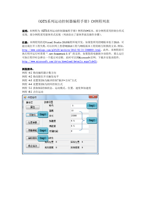
《GTS系列运动控制器编程手册》C#例程列表说明:本例程为《GTS系列运动控制器编程手册》例程的C#版本,部分例程采用控制台形式实现,部分例程采用窗体形式实现(列表给出了窗体界面及操作步骤)。
注意:本例程用的是Visual Studio 2010编程环境开发,如果您所用的VS版本低于2010,可能出现打开工程失败,可以在网上查看VS2010工程与VS低版本工程的相互转换的文章,例如:/glf123/archive/2012/02/24/2366934.html。
此外,本例程的可执行程序运行时需要“.net framework 3.5”的支持,如果您的电脑缺少该组件,那么运行可执行程序时会弹出一个提示对话框,此时可以到Microsoft官网,下载并安装该组件。
/zh-cn/download/details.aspx?id=21。
例程清单:例程4-1 修改编码器计数方向例程4-2 修改限位开关触发电平例程4-3 设置第1轴为脉冲控制“脉冲+方向”方式例程4-4 设置第1轴为闭环控制方式例程5-1 获取轴1的轴状态、运动模式、位置、速度和加速度例程6-1 点位运动Step1Step3Step2Step4Step5例程6-2 Jog运动例程6-3 PT静态FIFO Step1 Step2Step3Step4Step5Step1 Step2Step3Step4Step5例程6-4 PT动态FIFO例程6-5 电子齿轮跟随Step1Step2Step3Step4Step1 Step2 Step3例程6-7 Follow单FIFO模式Step1Step2Step3Step4例程6-8 Follow双FIFO切换Step1Step1Step2Step3例程6-9 建立坐标系例程6-10 直线插补例程例程6-11 圆弧插补例程例程6-12 插补FIFO管理例程6-13 前瞻预处理例程例程6-14 刀向跟随功能GT_BufMove() 例程6-15 刀向跟随功能GT_BufGear()例程 6-16 刀向跟随功能——实际工件加工 (例程6-9~16集成在一起)例程 6-17 PVT 描述方式 例程 6-18 Complete 描述方式 例程 6-19 Percent 描述方式 例程 6-20 Continuous 描述方式 例程 7-1 访问数字IO例程 7-2 读取8个轴编码器和辅助编码器位置值Step1Step2Step3Step1 Step2例程7-3 访问DAC例程7-4 访问ADCStep1Step4Step5Step2Step3Step1Step2例程 8-2 Home 回原点例程 8-3 Home+Index 回原点Step1Step2Step3Step2Step4 Step5 Step6Step1Step2Step3Step4Step5例程8-4 探针捕获例程8-5 HSIO捕获用法示例例程9-1 软限位使用例程10-1 运动程序单线程累加求和例程10-2 运动程序多线程累加求和例程11-1 读取运动控制器版本号例程11-2 电机到位检测功能例程11-3 自动回原点例程11-4 位置比较输出指令详细的用法Step1 Step2Step3Step4 Step5。
GT用户手册
冠图高精度户内外写真机T-1600D使用说明书﹡本说明适用于T-1600D/T-1600S一、安全使用须知 (3)1.1关于标记 (3)1.2关于机器上的标签 (6)二、机器组件 (7)操作面板: (7)三、机器组装 (8)四、软件安装 (11)4.1 机器驱动安装 (11)4.2 打印软件安装 (11)五、开机准备 (12)5.1开始注墨: (12)5.2清洗喷头: (12)六、校准机器 (14)6.1双向校准 (14)6.2打印作业 (16)6.3暂停/取消打印操作 (16)七、菜单列表及说明 (18)7.1【PRINT QUALITY】 (18)7.2【CLEANING】 (18)7.3【FUNCTION】 (19)一、安全使用须知1.1关于标记关于和标记不能拆开,修理或改装否则会导致火灾或非正常操作引起的伤害请使用与机器上标明的额定值相同的电源使用任何其他的电源会导致火灾或电击用地线将机器接地。
否则在出现机械故障时会造成电击危险。
当处于异常状态时,不要使用。
(例如:冒烟,烤焦味道,异常杂音等等)否则会出现火灾或电击危险。
首先立即关掉子电源,然后立即关掉主电源。
请使用原厂配带的电源线使用不标准的电源线可能导致火灾或电器故障。
不要使液体,进入机器内。
这些物品能造成火灾拆包、安装和移动必须由四个或更否则易造成机器跌落,引起伤害。
用连接螺钉将机器固定在支架上否则导致卷筒跌落,造成伤害安装在平坦稳定的位置否则导致卷筒跌落,造成否则会造成伤害卷筒材料必须安装在预先设定好的滚轴的位置否则导致卷筒跌落,造成伤害。
否则机器会翻倒造成伤害操作时不要把手伸到打印部件的内部否则会造成伤害。
..如果墨水飞溅入眼睛请立刻用水清洗改前盖板的时候注意夹伤手指。
请确认墨水存放位置远离儿童。
1.2关于机器上的标签关闭前盖时,小心夹到手指.操作时不要把手伸到打印部件的内部。
注意:除了W ARNING和CAUTION还有其他标签,请使用时注意观察,以防发生意外。
Mitsubishi Electric GT25系列机器人控制器产品说明书
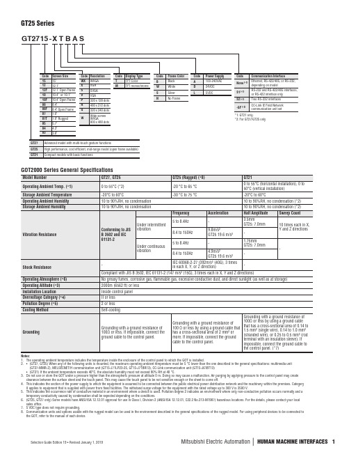
GT25 SeriesNotes:1. The operating ambient temperature includes the temperature inside the enclosure of the control panel to which the GOT is installed.2. • (GT27, GT25) When any of the following units is mounted, the maximum operating ambient temperature must be 5 °C lower than the one described in the general specifications: multimedia unit(GT27-MMR-Z), MELSECNET/H communication unit (GT15-J71LP23-25, GT15-J71BR13), CC-Link communication unit (GT15-J61BT13) • (GT21) If the ambient temperature exceeds 40°C, the absolute humidity must not exceed 90% RH at 40 °C.3. Do not use or store the GOT under a pressure higher than the atmospheric pressure at altitude 0 m. Doing so may cause a malfunction. Air purging by applying pressure to the control panel may createclearance between the surface sheet and the touch panel. This may cause the touch panel to be not sensitive enough or the sheet to come off.4. This indicates the section of the power supply to which the equipment is assumed to be connected between the public electrical power distribution network and the machinery within the premises. CategoryII applies to equipment that is supplied with power from fixed facilities. The withstand surge voltage for the equipment with the rated voltage up to 300 V is 2500 V.5. This indicates the occurrence rate of conductive material in an environment where a device is used. Pollution degree 2 indicates an environment where only non-conductive pollution occurs normally and atemporary conductivity caused by condensation shall be expected depending on the conditions.6. (GT25, GT27 only) Some models have ANSI/ISA 12.12.01 approval for use in Class I, Division 2 (ANSI/ISA 12.12.01, C22.2 No.213-M1987) hazardous locations. For the details, please contact your localsales office.7. 5 VDC type does not require grounding.8. Communication units and options usable with the rugged model can be used in the environment described in the general specifications of the rugged model. For using peripheral devices to be connected tothe GOT, refer to the manual of each device.GOT2000 Series General Specificationsn H U M A N M A C H I N E I N T E R F A C E SGT25 Power Supply Specificationsdoing so may damage or soil the GOT or cause foreign matter to enter the GOT, resulting in a failure or malfunction+2B +2 0(0.08)(0.08)(0)(unit: mm)GT25 Panel Cut Dimensionsn H U M A N M A C H I N E I N T E R F A C E SGT25 Performance SpecificationsNotes:1. As a characteristic of liquid crystal display panels, bright dots (always lit) and dark dots (never lit) may appear on the panel. Since liquid crystal display panels comprise a great number of display elements, the appearance of bright and dark dots cannot be reduced to zero. Individual differences in liquid crystal display panels may cause differences in color, uneven brightness and flickering. Note that these phenomena are characteristics of liquid crystal display panels and it does not mean the products are defective or damaged.2. Flickering may occur due to vibration, shock, or the display colors.3. When a stylus is used, the touch panel has a life of 100 thousand touches. The stylus must satisfy the following specifications: • Material: polyacetal resin • Tip radius: 0.8 mm or more4. To prevent the display section from burning in and lengthen the backlight life, enable the screen save function and turn off the backlight.5. If you touch two points or more simultaneously on the touch panel, a touch switch near the touched points may operate unexpectedly. Do not touch two points or more simultaneously on the touch panel.6. To conform to IP67F, close the USB environmental protection cover by pushing the [PUSH] mark firmly. (To conform to IP2X, open the USB environmental protection cover.) Note that the structure does not guarantee protection in all users’ environments. The GOT may not be used in certain environments where it is subjected to splashing oil or chemicals for a long period of time or soaked in oil mist.7. To conform to IP67F attach the environmental protection sheet. Note that the structure does not guarantee protection in all users’ environments. The GOT may not be used in certain environments where it is subjected to splashing oil or chemicals for a long period of time or soaked in oil mist.8. The minimum size of a key that can be arranged. To ensure safe use of the product, the following settings are recommended: • Key size: 16 x 16 dots or larger • Distance between keys: 16 dots or more 9. The suffix “F” of IP67F is a symbol that indicates protection rate against oil. It is described in the Appendix of Japanese Industrial Standard JIS C 0920.Notes:1. As a characteristic of liquid crystal display panels, bright dots (always lit) and dark dots (never lit) may appear on the panel. Since liquid crystal display panels comprise a great number of display elements, theappearance of bright and dark dots cannot be reduced to zero. Individual differences in liquid crystal display panels may cause differences in color, uneven brightness and flickering. Note that these phenomena are characteristics of liquid crystal display panels and it does not mean the products are defective or damaged.2. Flickering may occur due to vibration, shock, or the display colors.3. When a stylus is used, the touch panel has a life of 100 thousand touches. The stylus must satisfy the following specifications: • Material: polyacetal resin • Tip radius: 0.8 mm or more4. To prevent the display section from burning in and lengthen the backlight life, enable the screen save function and turn off the backlight.5. If you touch two points or more simultaneously on the touch panel, a touch switch near the touched points may operate unexpectedly. Do not touch two points or more simultaneously on the touch panel.6. To conform to IP67F, close the USB environmental protection cover by pushing the [PUSH] mark firmly. (To conform to IP2X, open the USB environmental protection cover.) Note that the structure does notguarantee protection in all users’ environments. The GOT may not be used in certain environments where it is subjected to splashing oil or chemicals for a long period of time or soaked in oil mist.7. To conform to IP67F attach the environmental protection sheet. Note that the structure does not guarantee protection in all users’ environments. The GOT may not be used in certain environments where it issubjected to splashing oil or chemicals for a long period of time or soaked in oil mist.8. The minimum size of a key that can be arranged. To ensure safe use of the product, the following settings are recommended: • Key size: 16 x 16 dots or larger • Distance between keys: 16 dots or more9. The suffix “F” of IP67F is a symbol that indicates protection rate against oil. It is described in the Appendix of Japanese Industrial Standard JIS C 0920.。
GT系列运动控制器 用户手册
前言
前言
感谢选用固高运动控制器
为回报客户,我们将以品质一流的运动控制器、完善的售后服务、高效的技术支持,帮 助您建立自己的控制系统。
固高产品的更多信息
固高科技的网址是 。在我们的网页上可以得到更多关 于公司和产品的信息,包括:公司简介、产品介绍、技术支持、产品最新发布等等。
用户手册的用途
用户通过阅读本手册,能够了解 GT 系列运动控制器的基本结构,正确安装运动控制器, 连接控制器与电机控制系统,完成运动控制系统的基本调试。
用户手册的使用对象
本编程手册适用于,具有硬件基本知识,对控制有一定了解的工程人员。
用户手册的主要内容
本手册由三章内容和附录组成。第一章“概述”,简介 GT 系列运动控制器 及如何构成电机控制系统;第二章“快速使用”,介绍控制卡安装、接线和驱动程 序的安装;第三章“系统调试”,介绍利用控制卡配套软件,进行系统调试;附录 提供了:控制器技术参数;位置、速度和加速度设置;典型接线;故障处理;配 套软件使用说明。
地址线定义图23jp1基地址开关默认定义表22运动控制器基地址开关选择表基地址hex十进制a9a8a7a6a5a40x1002560x1202880x1403200x1603520x1803840x1a0x1c0x1e0x2005120x2205440x2405760x2606080x2806400x2a0x2c0x2e0x300默认768offoff0x3208000x3408320x3608640x3808960x3a0x3c0x3e第二章快速使用23pc机已占用地址表isa总线地址分配十六进制十进制功能00001f003102003f3263中断控制器04005f6495定时器06006f96111键盘07007f112127实时时钟08009f128159页寄存器0a00b160191中断控制器0c00d0f00f240255数学协处理器1f01f496504硬盘驱动器20020f512527游戏口210217528535扩展单元27827f630639并行口2b02d688735可选择2f82f760767异步通信口30031f768799原型卡36036f864879网络卡37837f888895并行口38038f896911390393912915保留3a03a3b03b单显3c03c3d03d976991彩显3f03f10081015软盘驱动器3f83f10161023异步通信口390x393异步通信口2312中断选择jp2运动控制器提供时间中断和事件中断信号供主机使用
GTS 激光控制说明书
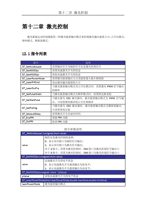
第十二章激光控制激光振镜运动控制器提供三种激光能量输出模式来控制激光输出能量大小:占空比模式,频率模式,模拟量模式。
12.1指令列表无效FPK信号12.2 重点说明12.2.1 激光能量输出方式激光振镜运动控制器可提供四种激光能量输出模式,除模拟量输出模式外,首先需要将对应的信号输出口从轴控信号输出切换到激光信号输出,即调用函数GT_SetAxisAsLaser(1),然后再分别根据如下模式操作:●占空比输出模式1:通过设置频率和占空比调节激光器能量。
使用时调用函数GT_LaserPowerMode()设置为占空比输出模式,调用函数GT_LaserOutFrq()设置PWM信号的输出频率,调用函数GT_LaserPrfCmd()设置PWM信号的输出占空比,调用函数GT_SetHSIOOpt()启动输出。
●频率输出模式:通过设置频率和脉宽调节激光器能量。
使用时调用函数GT_LaserPowerMode设置为频率输出模式,调用函数GT_LaserPrfCmd()设置频率输出值,调用函数GT_SetHSIOOpt()启动输出。
●模拟量输出模式:通过设置输出电压调节激光器能量。
使用时调用函数GT_LaserPowerMode()设置为DA 输出模式,调用函数GT_LaserPrfCmd()设置DA输出值,调用函数GT_SetHSIOOpt() 启动输出。
●占空比输出模式2:通过设置频率和占空比调节激光器能量,激光开关信号为恒高信号。
使用时调用函数GT_LaserPowerMode()设置为占空比输出模式2,调用函数GT_LaserOutFrq()设置占空比信号输出频率,调用函数GT_LaserPrfCmd()设置占空比信号输出占空比,立即模式调用函数GT_SetHSIOOpt()启动输出。
当激光能量输出模式为占空比输出模式或者频率输出模式时,其输出的PWM信号占空当激光能量输出模式为模拟量输出时,范围为0V~10V。
通用型运动控制器GT-400-SX、GT-400-SV
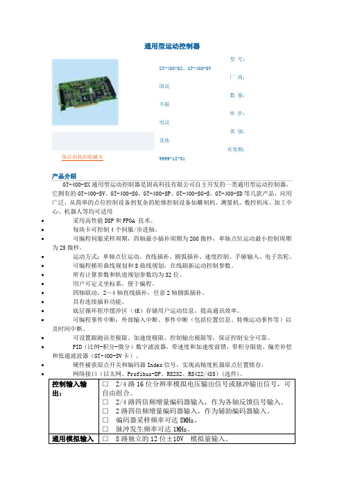
通用型运动控制器∙∙保存到我的收藏夹型号:GT-400-SX、GT-400-SV厂商:固高数量:不限单价:电议类别:其他有效期:9999-12-31产品介绍GT-400-SX通用型运动控制器是固高科技有限公司自主开发的一类通用型运动控制器,它拥有的GT-400-SV、GT-400-SG、GT-400-SP、GT-400-SG-S、GT-400-SD等几款产品,应用广泛,从简单的点位控制设备到复杂的轮廓控制设备如雕刻机、测量机、数控机床、加工中心、机器人等均可适用∙采用高性能DSP和FPGA 技术。
∙每块卡可控制4个伺服/步进轴。
∙可编程伺服采样周期,四轴最小插补周期为200微秒,单轴点位运动最小控制周期为25微秒。
∙运动方式:单轴点位运动、直线插补、圆弧插补、速度控制、手脉输入、电子齿轮。
∙可编程梯形曲线规划和S曲线规划,在线刷新运动控制参数。
∙所有计算参数和轨迹规划参数均为32位。
∙用户可定义坐标系,便于编程。
∙四轴联动,2~4轴直线插补,任意2轴圆弧插补。
∙具有连续插补功能。
∙底层循环程序缓冲区(4K)存储用户运动信息,提高通讯效率。
∙可编程事件中断:外部输入中断、事件中断(包括位置信息、特殊运动事件等)以及时间中断。
∙可设置跟随误差极限、加速度极限、控制输出极限等,保证控制安全可靠。
∙PID(比例-积分-微分)数字滤波器,带速度和加速度前馈,带积分限值、偏差补偿和低通滤波器(GT-400-SV卡)。
∙硬件捕获原点开关和编码器Index信号,实现高精度机器原点位置锁存。
∙网络接口(以太网、Profibus-DP、RS232、RS422/485)(选件)。
控制输入输出:□ 2/4路16位分辨率模拟电压输出信号或脉冲输出信号,可自由组合。
□ 2/4路四倍频增量编码器输入,作为各轴反馈信号输入。
□ 2路四倍频增量编码器输入,作为辅助编码器输入。
□编码器采样频率可达8MHz。
□脉冲发生频率可达1MHz。
- 1、下载文档前请自行甄别文档内容的完整性,平台不提供额外的编辑、内容补充、找答案等附加服务。
- 2、"仅部分预览"的文档,不可在线预览部分如存在完整性等问题,可反馈申请退款(可完整预览的文档不适用该条件!)。
- 3、如文档侵犯您的权益,请联系客服反馈,我们会尽快为您处理(人工客服工作时间:9:00-18:30)。
固高科技有限公司 保留所有权力
固高科技有限公司(以下简称固高科技)保留在不事先通知的情况下,修改本手册中的 产品和产品规格等文件的权力。
固高科技不承担由于使用本手册或本产品不当,所造成直接的、间接的、特殊的、附带 的或相应产生的损失或责任。
固高科技具有本产品及其软件的专利权、版权和其它知识产权。未经授权,不得直接或 者间接地复制、制造、加工、使用本产品及其相关部分。
第三章 系统调试------------------------------------------------------------------------------------------------------------3-1 3.1 系统初始化.............................................................................................................................................3-1 3.2 设置控制输出,驱动使能(轴开启).................................................................................................3-3 3.3 PID 参数调节 .......................................................................................................................................3-4 3.4 以梯形曲线运动模式实现单轴运动.....................................................................................................3-4
第二章 快速使用 ------------------------------------------------------------------------------------------------------------2-1 2.1 开箱检查...............................................................................................................................................2-1 2.2 GT 系列运动控制卡的外形结构 ........................................................................................................2-1 2.3 安装步骤.................................................................................................................................................2-2 2.3.1 步骤 1:在运动控制卡上设置跳线(仅对 ISA 卡).............................................................2-2 2.3.2 步骤 2:将运动控制卡插入计算机.........................................................................................2-5 2.3.3 步骤 3:安装控制器通讯驱动(Windows 操作系统) .........................................................2-5 2.3.4 步骤 4:建立主机与运动控制器的通讯(Windows 操作系统).........................................2-6 2.3.5 步骤 5:联接电机和驱动器.....................................................................................................2-6 2.3.6 步骤 6:联接控制卡和端子板.................................................................................................2-7 2.3.7 步骤 7:联接驱动器、系统输入/输出和端子板....................................................................2-7
您也可以通过电话(0755-26970839来自咨询关于公司和产品的更多信息。
技术支持和售后服务
您可以通过以下途径获得我们的技术支持和售后服务: ♦ 电子邮件: support@; ♦ 电话: (0755) 26970835 ♦ 发函至:深圳市高新技术产业园南区园深港产学研基地西座二楼 W211 室 固高科技(深圳)有限公司 邮编:518057
运动中的机器有危险!使用者有责任在机器中设计有效的出错处理和 安全保护机制,固高科技没有义务或责任对由此造成的附带的或相应 产生的损失负责。
前言
前言
感谢选用固高运动控制器
为回报客户,我们将以品质一流的运动控制器、完善的售后服务、高效的技术支持,帮 助您建立自己的控制系统。
固高产品的更多信息
固高科技的网址是 。在我们的网页上可以得到更多关 于公司和产品的信息,包括:公司简介、产品介绍、技术支持、产品最新发布等等。
Googol Technology (HK) Ltd
Addr: Room 3639,Annex Building
Hong Kong University of Science and Technology,
Hong Kong
Tel:
(852) 2358-1033
Fax:
(852) 2358-4931
固高科技(深圳)有限公司
地 址:深圳市高新技术产业园南区深港产学研基地西座 二层 W211 室
电 话:0755-26970823 26970819 26970824 传 真:0755-26970821 电子邮件:support@ 网 址:
E-mail: info@
Web:
GT 系列运动控制器 用户手册
务必将此手册交给用户 非常感谢您选购 GT 系列运动控制器 在您使用之前,请仔细阅读此手册,确保正确使用。 请将此手册妥善保存,以备随时查阅。
版权申明
版权声明
附录 C 典型接线-----------------------------------------------------------------------------------------------------------C-1 C.1 控制器与 Panasonic 驱动器速度控制方式接线 ................................................................................. C-1 C.2 控制器与 Panasonic 驱动器位置控制方式接线 ................................................................................. C-2 C.3 控制器与 SANYO DENKI PV1 系列驱动器速度控制方式接线 ...................................................... C-3 C.4 控制器与 SANYO DENKI PV1 系列驱动器位置控制方式接线 ...................................................... C-4 C.5 控制器与 SANYO DENKI PY0/PY2 系列驱动器速度控制方式接线........................................................ C-5 C.6 控制器与 SANYO DENKI PY0/PY2 系列驱动器位置控制方式接线........................................................ C-6 C.7 控制器与 SANYO DENKI PU 系列驱动器速度控制方式接线 ................................................................. C-7 C.8 控制器与YASKAWASERVOPACK系列驱动器速度/力矩控制方式接线............................................................... C-8 C.9 控制器与 YASKAWA SERVOPACK 系列驱动器位置控制方式接线........................................................ C-9 C.10 控制器与 YASKAWA SGDE 系列驱动器位置控制方式接线 ....................................................... C-10
相关文件
关于 GT 系列运动控制器的编程,请参见随产品配套的《GT 系列运动控制 器编程手册》。
I
目录
目录
第一章 概述------------------------------------------------------------------------------------------------------------------1-1 1.1 简介..........................................................................................................................................................1-1 1.2 GT 系列运动控制器型号及含义 ...........................................................................................................1-1 1.3 GT 系列控制器功能列表 .......................................................................................................................1-2 1.4 电机控制系统的基本组成.....................................................................................................................1-3
