建筑结构设计及材料中英文对照外文翻译文献
建筑结构设计中英文对照外文翻译文献
中英文对照外文翻译(文档含英文原文和中文翻译)Create and comprehensive technology in the structure globaldesign of the buildingThe 21st century will be the era that many kinds of disciplines technology coexists , it will form the enormous motive force of promoting the development of building , the building is more and more important too in global design, the architect must seize the opportunity , give full play to the architect's leading role, preside over every building engineering design well. Building there is the global design concept not new of architectural design,characteristic of it for in an all-round way each element not correlated with building- there aren't external environment condition, building , technical equipment,etc. work in coordination with, and create the premium building with the comprehensive new technology to combine together.The premium building is created, must consider sustainable development , namely future requirement , in other words, how save natural resources as much as possible, how about protect the environment that the mankind depends on for existence, how construct through high-quality between architectural design and building, in order to reduce building equipment use quantity andreduce whole expenses of project.The comprehensive new technology is to give full play to the technological specialty of every discipline , create and use the new technology, and with outside space , dimension of the building , working in coordination with in an all-round way the building component, thus reduce equipment investment and operate the expenses.Each success , building of engineering construction condense collective intelligence and strength; It is intelligence and expectation that an architect pays that the building is created; The engineering design of the building is that architecture , structure , equipment speciality compose hardships and strength happenning; It is the diligent and sweat paid in design and operation , installation , management that the construction work is built up .The initial stage of the 1990s, our understanding that the concept of global design is a bit elementary , conscientious to with making some jobs in engineering design unconsciously , make some harvest. This text Hangzhou city industrial and commercial bank financial comprehensive building and Hangzhou city Bank of Communications financial building two building , group of " scientific and technological progress second prize " speak of from person who obtain emphatically, expound the fact global design - comprehensive technology that building create its , for reach global design outstanding architect in two engineering design, have served as the creator and persons who cooperate while every stage design and even building are built completely.Two projects come into operation for more than 4 years formally , run and coordinate , good wholly , reach the anticipated result, accepted and appreciated by the masses, obtain various kinds of honor .outstanding to design award , progress prize in science and technology , project quality bonus , local top ten view , best model image award ,etc., the ones that do not give to the architect and engineers without one are gratified and proud. The building is created Emphasizing the era for global design of the building, the architects' creation idea and design method should be broken through to some extent, creation inspirations is it set up in analysis , building of global design , synthesize more to burst out and at the foundation that appraise, learn and improve the integration capability exactly designed in building , possess the new knowledge system and thinking method , merge multi-disciplinary technology. We have used the new design idea in above-mentioned projects, have emphasized the globality created in building .Is it is it act as so as to explain to conceive to create two design overview and building of construction work these now.1) The financial comprehensive building of industrial and commercial bank of HangZhou,belong to the comprehensive building, with the whole construction area of 39,000 square meters, main building total height 84, 22, skirt 4 of room, some 6 storeys, 2 storeys of basements.Design overall thinking break through of our country bank building traditional design mode - seal , deep and serious , stern , form first-class function, create of multi-functional type , the style of opening , architecture integrated with the mode of the international commercial bank.The model of the building is free and easy, opened, physique was made up by the hyperboloid, the main building presented " the curved surface surrounded southwards ", skirt room presents " the curved surface surrounded northwards ", the two surround but become intension of " gathering the treasure ".Building flourishing upwards, elevation is it adopt large area solid granite wall to design, the belt aluminium alloy curtain wall of the large area and some glass curtain walls, and interweave the three into powerful and vigorous whole , chase through model and entity wall layer bring together , form concise , tall and straight , upward tendency of working up successively, have distinct and unique distinctions.Building level and indoor space are designed into a multi-functional type and style of opening, opening, negotiate , the official working , meeting , receiving , be healthy and blissful , visit combining together. Spacious and bright two storeys open in the hall unifiedly in the Italian marble pale yellow tone , in addition, the escalator , fountain , light set off, make the space seem very magnificent , graceful and sincere. Intelligent computer network center, getting open and intelligent to handle official business space and all related house distribute in all floor reasonably. Top floor round visit layer, lift all of Room visit layer , can have a panoramic view of the scenery of the West Lake , fully enjoy the warmth of the nature. 2) The financial building of Bank of Communications of Hangzhou, belong to the purely financial office block, with the whole construction area of 19,000 square meters, the total height of the building is 39.9 meters, 13 storeys on the ground, the 2nd Floor. Live in building degree high than it around location , designer have unique architectural appearance of style architectural design this specially, its elevation is designed into a new classical form , the building base adopts the rough granite, show rich capability , top is it burn granite and verticality bar and some form aluminum windows make up as the veneer to adopt, represent the building noble and refined , serious personality of the bank.While creating in above-mentioned two items, besides portraying the shape of the building and indoor space and outside environment minister and blending meticulously, in order to achieve the outstanding purpose of global design of the building , the architect , still according to the region and project characteristic, put forward the following requirement to every speciality:(1) Control the total height of the building strictly;(2) It favorable to the intelligent comfortable height of clearances to create; (3) Meet thefloor area of owner's demand;(4)Protect the environment , save the energy , reduce and make the investment;(5) Design meticulously, use and popularize the new technology; (6)Cooperate closely in every speciality, optimization design.Comprehensive technologyThe building should have strong vitality, there must be sustainable development space, there should be abundant intension and comprehensive new technology. Among above-mentioned construction work , have popularized and used the intelligent technology of the building , has not glued and formed the flat roof beam of prestressing force - dull and stereotyped structure technology and flat roof beam structure technology, baseplate temperature mix hole , technology of muscle and base of basement enclose new technology of protecting, computer control STL ice hold cold air conditioner technology, compounding type keeps warm and insulates against heat the technology of the wall , such new technologies as the sectional electricity distribution room ,etc., give architecture global design to add the new vitality of note undoubtedly.1, the intelligent technology of the buildingIn initial stage of the 1990s, the intelligent building was introduced from foreign countries to China only as a kind of concept , computer network standard is it soon , make information communication skeleton of intelligent building to pursue in the world- comprehensive wiring system becomes a kind of trend because of 10BASE-T. In order to make the bank building adapt to the development of the times, the designer does one's utmost to recommend and design the comprehensive wiring system with the leading eyes , this may well be termed the first modernized building which adopted this technical design at that time.(1) Comprehensive wiring system one communication transmission network, it make between speech and data communication apparatus , exchange equipment and other administrative systems link to each other, make the equipment and outside communication network link to each other too. It include external telecommunication connection piece and inside information speech all cable and relevant wiring position of data terminal of workspace of network. The comprehensive wiring system adopts the products of American AT&T Corp.. Connected up the subsystem among the subsystem , management subsystem , arterial subsystem and equipment to make up by workspace subsystem , level.(2) Automated systems of security personnel The monitoring systems of security personnel of the building divide into the public place and control and control two pieces of systemequipment with the national treasury special-purposly synthetically.The special-purpose monitoring systems of security personnel of national treasury are in the national treasury , manage the storehouse on behalf of another , transporting the paper money garage to control strictly, the track record that personnel come in and go out, have and shake the warning sensor to every wall of national treasury , the camera, infrared microwave detector in every relevant rooms, set up the automation of controlling to control.In order to realize building intellectuality, the architect has finished complete indoor environment design, has created the comfortable , high-efficient working environment , having opened up the room internal and external recreation space not of uniform size, namely the green one hits the front yard and roofing, have offered the world had a rest and regulated to people working before automation is equipped all day , hang a design adopt the special building to construct the node in concrete ground , wall at the same time.2, has not glued and formed the flat roof beam of prestressing force- dull and stereotyped structure technology and flat roof beam structure technologyIn order to meet the requirement with high assurance that the architect puts forward , try to reduce the height of structure component in structure speciality, did not glue and form the flat roof beam of prestressing force concrete - dull and stereotyped structure technology and flat roof beam structure technology after adopting.(1) Adopt prestressing force concrete roof beam board structure save than ordinary roof beam board concrete consumption 15%, steel consumption saves 27%, the roof beam reduces 300mm high.(2) Adopt flat roof beam structure save concrete about 10% consumption than ordinary roof beam board, steel consumption saves 6.6%, the roof beam reduces 200mm high.Under building total situation that height does not change , adopt above-mentioned structure can make the whole building increase floor area of a layer , have good economic benefits and social benefit.3, the temperature of the baseplate matches muscle technologyIn basement design , is it is it is it after calculating , take the perimeter to keep the construction technology measure warm to split to resist to go on to baseplate, arrange temperature stress reinforcing bar the middle cancelling , dispose 2 row receives the strength reinforcing bar up and down only, this has not only save the fabrication cost of the project but also met the basement baseplate impervious and resisting the requirement that splits.4, the foundation of the basement encloses and protects the new technology of design and operationAdopt two technological measures in enclosing and protecting a design:(1) Cantilever is it is it hole strength is it adopt form strengthen and mix muscle technology to design to protect to enclose, save the steel and invite 60t, it invests about 280,000 to save.(2) Is it is it protect of of elevation and keep roof beam technology to enclose , is it protect long to reduce 1.5m to enclose all to reduce, keep roof beam mark level on natural ground 1.5m , is it is it protect of lateral pressure receive strength some height to enclose to change, saving 137.9 cubic meters of concrete, steel 16.08t, reduces and invests 304,000 yuan directly through calculating.5, ice hold cold air conditioner technologyIce hold cold air conditioner technology belong to new technology still in our country , it heavy advantage that the electricity moves the peak and operates the expenses sparingly most. In design, is it ice mode adopt some (weight ) hold mode of icing , is it ice refrigeration to be plane utilization ratio high to hold partly to hold, hold cold capacity little , refrigeration plane capacity 30%-45% little than routine air conditioner equipment, one economic effective operational mode.Hold the implementation of the technology of the cold air conditioner in order to cooperate with the ice , has used intelligent technology, having adopted the computer to control in holding and icing the air conditioner system, the main task has five following respects:(1) According to the demand for user's cold load , according to the characteristic of the structure of the electric rate , set up the ice and hold the best operation way of the cold system automatically, reduce the operation expenses of the whole system;(2) Fully utilize and hold the capacity of the cold device, should try one's best to use up all the cold quantity held basically on the same day;(3) Automatic operation state of detection system, ensure ice hold cold system capital equipment normal , safe operation;(4) Automatic record parameter that system operate, display system operate flow chart and type systematic operation parameter report form;(5) Predict future cooling load, confirm the future optimization operation scheme.Ice hold cold air conditioner system test run for some time, indicate control system to be steady , reliable , easy to operate, the system operates the energy-conserving result remarkably.6, the compounding type keeps in the wall warm and insulates against heat To the area of Hangzhou , want heating , climate characteristic of lowering the temperature in summer in winter, is it protect building this structural design person who compound is it insulate against heat the wall to keep warm to enclose specially, namely: Fit up , keep warm , insulate against heat the three not to equal to the body , realize building energy-conservation better.Person who compound is it insulate against heat wall to combine elevation model characteristic , design aluminium board elevation renovation material to keep warm, its structure is: Fill out and build hollow brick in the frame structure, do to hang the American Fluorine carbon coating inferior mere aluminium board outside the hollow brick wall.Aluminium board spoke hot to have high-efficient adiabatic performance to the sun, under the same hot function of solar radiation, because the nature , color of the surface material are different from coarse degree, whether can absorb heat have great difference very , between surface and solar radiation hot absorption system (α ) and material radiation system (Cλ ) is it say to come beyond the difference this. Adopt α and Cλ value little surface material have remarkable result , board α、Cλ value little aluminium have, its α =0.26, Cλ =0.4, light gray face brick α =0.56, Cλ =4.3.Aluminium board for is it hang with having layer under air by hollow brick to do, because aluminium board is it have better radiation transfer to hot terms to put in layer among the atmosphere and air, this structure is playing high-efficient adiabatic function on indoor heating too in winter, so, no matter or can well realize building energy-conservation in winter in summer.7, popularize the technology of sectional electricity distribution roomConsider one layer paves Taxi " gold " value , the total distribution of the building locates the east, set up voltage transformer and low-voltage distribution in the same room in first try in the design, make up sectional electricity distribution room , save transformer substation area greatly , adopt layer assign up and down, mixing the switchyard system entirely after building up and putting into operation, the function is clear , the overall arrangement compactness is rational , the systematic dispatcher is flexible . The technology have to go to to use and already become the model extensively of the design afterwards.ConclusionThe whole mode designed of the building synthetically can raise the adaptability of the building , it will be the inevitable trend , environmental consciousness and awareness of saving energy especially after strengthening are even more important. Developing with the economy , science and technology constantly in our country, more advanced technology and scientific and technical result will be applied to the building , believe firmly that in the near future , more outstanding building global design will appear on the building stage of our country. We will be summarizing, progressing constantly constantly, this is that history gives the great responsibility of architect and engineer.译文:建筑结构整体设计-建筑创作和综合技术21世纪将是多种学科技术并存的时代,它必将形成推动建筑发展的巨大动力,建筑结构整体设计也就越来越重要,建筑师必须把握时机,充分发挥建筑师的主导作用,主持好各项建筑工程设计。
高层建筑与钢结构外文文献翻译中英文
高层建筑与钢结构外文文献翻译(含:英文原文及中文译文)文献出处:Structural Engineer Journal of the Institution of Structural Engineer, 2014, 92, pp: 26-29.英文原文Talling building and Steel constructionCollins MarkAlthough there have been many advancements in building construction technology in general. Spectacular achievements have been made in the design and construction of ultrahigh-rise buildings.The early development of high-rise buildings began with structural steel fraing. Reinforced concrete and stressed-skin tube systems have since been economically and competitively used in a number of structures for both residential and commercial purposes. The high-rise buildings ranging from 50 to 110 stories that are being built all over the United States are the result of innovations and development of new structural systems.Greater height entails increased column and beam sizes to make buildings more rigid so that under wind load they will not sway beyond an acceptable limit. Excessive lateral sway may cause serious recurring damage to partitions, ceilings. and other architectural details. In addition, excessive sway may cause discomfort to the occupants of the building because their perception of such motion. Structural systems of reinforcedconcrete, as well as steel,take full advantage of inherent potential stiffness of the total building and therefore require additional stiffening to limit the sway.In a steel structure, for example, the economy can be defined in terms of the total average quantity of steel per square foot of floor area of the building. Curve A in Fig .1 represents the average unit weight of a conventional frame with increasing numbers of stories. Curve B represents the average steel weight if the frame is protected from all lateral loads. The gap between the upper boundary and the lower boundary represents the premium for height for the traditional column-and-beam frame. Structural engineers have developed structural systems with a view to eliminating this premium.Systems in steel. Tall buildings in steel developed as a result of several types of structural innovations. The innovations have been applied to the construction of both office and apartment buildings.Frame with rigid belt trusses. In order to tie the exterior columns of a frame structure to the interior vertical trusses, a system of rigid belt trusses at mid-height and at the top of the building may be used. A good example of this system is the First Wisconsin Bank Building(1974) in Milwaukee.Framed tube. The maximum efficiency of the total structure of a tall building, for both strength and stiffness,to resist wind load can beachieved only if all column element can be connected to each other in such a way that the entire building acts as a hollow tube or rigid box in projecting out of the ground. This particular structural system was probably used for the first time in the 43-story reinforced concrete DeWitt Chestnut Apartment Building in Chicago. The most significant use of this system is in the twin structural steel towers of the 110-story World Trade Center building in New YorkColumn-diagonal truss tube. The exterior columns of a building can be spaced reasonably far apart and yet be made to work together as a tube by connecting them with diagonal members interesting at the centre line of the columns and beams. This simple yet extremely efficient system was used for the first time on the John Hancock Centre in Chicago, using as much steel as is normally needed for a traditional 40-story building.Bundled tube. With the continuing need for larger and taller buildings, the framed tube or the column-diagonal truss tube may be used in a bundled form to create larger tube envelopes while maintaining high efficiency. The 110-story Sears Roebuck Headquarters Building in Chicago has nine tube, bundled at the base of the building in three rows. Some of these individual tubes terminate at different heights of the building, demonstrating the unlimited architectural possibilities of this latest structural concept. The Sears tower, at a height of 1450 ft(442m), is th e world’s tallest building.Stressed-skin tube system. The tube structural system was developed for improving the resistance to lateral forces (wind and earthquake) and the control of drift (lateral building movement ) in high-rise building. The stressed-skin tube takes the tube system a step further. The development of the stressed-skin tube utilizes the façade of the building as a structural element which acts with the framed tube, thus providing an efficient way of resisting lateral loads in high-rise buildings, and resulting in cost-effective column-free interior space with a high ratio of net to gross floor area.Because of the contribution of the stressed-skin façade, the framed members of the tube require less mass, and are thus lighter and less expensive. All the typical columns and spandrel beams are standard rolled shapes,minimizing the use and cost of special built-up members. The depth requirement for the perimeter spandrel beams is also reduced, and the need for upset beams above floors, which would encroach on valuable space, is minimized. The structural system has been used on the 54-story One Mellon Bank Center in Pittburgh.Systems in concrete. While tall buildings constructed of steel had an early start, development of tall buildings of reinforced concrete progressed at a fast enough rate to provide a competitive chanllenge to structural steel systems for both office and apartment buildings.Framed tube. As discussed above, the first framed tube concept fortall buildings was used for the 43-story DeWitt Chestnut Apartment Building. In this building ,exterior columns were spaced at 5.5ft (1.68m) centers, and interior columns were used as needed to support the 8-in . -thick (20-m) flat-plate concrete slabs.Tube in tube. Another system in reinforced concrete for office buildings combines the traditional shear wall construction with an exterior framed tube. The system consists of an outer framed tube of very closely spaced columns and an interior rigid shear wall tube enclosing the central service area. The system (Fig .2), known as the tube-in-tube system , made it possible to design the world’s present tallest (714ft or 218m)lightweight concrete building ( the 52-story One Shell Plaza Building in Houston) for the unit price of a traditional shear wall structure of only 35 stories.Systems combining both concrete and steel have also been developed, an examle of which is the composite system developed by skidmore, Owings &Merril in which an exterior closely spaced framed tube in concrete envelops an interior steel framing, thereby combining the advantages of both reinforced concrete and structural steel systems. The 52-story One Shell Square Building in New Orleans is based on this system.Steel construction refers to a broad range of building construction in which steel plays the leading role. Most steel construction consists oflarge-scale buildings or engineering works, with the steel generally in the form of beams, girders, bars, plates, and other members shaped through the hot-rolled process. Despite the increased use of other materials, steel construction remained a major outlet for the steel industries of the U.S, U.K, U.S.S.R, Japan, West German, France, and other steel producers in the 1970s.Early history. The history of steel construction begins paradoxically several decades before the introduction of the Bessemer and the Siemens-Martin (openj-hearth) processes made it possible to produce steel in quantities sufficient for structure use. Many of problems of steel construction were studied earlier in connection with iron construction, which began with the Coalbrookdale Bridge, built in cast iron over the Severn River in England in 1777. This and subsequent iron bridge work, in addition to the construction of steam boilers and iron ship hulls , spurred the development of techniques for fabricating, designing, and jioning. The advantages of iron over masonry lay in the much smaller amounts of material required. The truss form, based on the resistance of the triangle to deformation, long used in timber, was translated effectively into iron, with cast iron being used for compression members-i.e, those bearing the weight of direct loading-and wrought iron being used for tension members-i.e, those bearing the pull of suspended loading.The technique for passing iron, heated to the plastic state, betweenrolls to form flat and rounded bars, was developed as early as 1800;by 1819 angle irons were rolled; and in 1849 the first I beams, 17.7 feet (5.4m) long , were fabricated as roof girders for a Paris railroad station.Two years later Joseph Paxton of England built the Crystal Palace for the London Exposition of 1851. He is said to have conceived the idea of cage construction-using relatively slender iron beams as a skeleton for the glass walls of a large, open structure. Resistance to wind forces in the Crystal palace was provided by diagonal iron rods. Two feature are particularly important in the history of metal construction; first, the use of latticed girder, which are small trusses, a form first developed in timber bridges and other structures and translated into metal by Paxton ; and second, the joining of wrought-iron tension members and cast-iron compression members by means of rivets inserted while hot.In 1853 the first metal floor beams were rolled for the Cooper Union Building in New York. In the light of the principal market demand for iron beams at the time, it is not surprising that the Cooper Union beams closely resembled railroad rails.The development of the Bessemer and Siemens-Martin processes in the 1850s and 1860s suddenly open the way to the use of steel for structural purpose. Stronger than iron in both tension and compression ,the newly available metal was seized on by imaginative engineers, notably by those involved in building the great number ofheavy railroad bridges then in demand in Britain, Europe, and the U.S.A notable example was the Eads Bridge, also known as the St. Louis Bridge, in St. Louis (1867-1874), in which tubular steel ribs were used to form arches with a span of more than 500ft (152.5m). In Britain, the Firth of Forth cantilever bridge (1883-90) employed tubular struts, some 12 ft (3.66m) in diameter and 350 ft (107m) long. Such bridges and other structures were important in leading to the development and enforcement of standards and codification of permissible design stresses. The lack of adequate theoretical knowledge, and even of an adequate basis for theoretical studies, limited the value of stress analysis during the early years of the 20th century,as iccasionally failures,such as that of a cantilever bridge in Quebec in 1907,revealed.But failures were rare in the metal-skeleton office buildings;the simplicity of their design proved highly practical even in the absence of sophisticated analysis techniques. Throughout the first third of the century, ordinary carbon steel, without any special alloy strengthening or hardening, was universally used.The possibilities inherent in metal construction for high-rise building was demonstrated to the world by the Paris Exposition of 1889.for which Alexandre-Gustave Eiffel, a leading French bridge engineer, erected an openwork metal tower 300m (984 ft) high. Not only was theheight-more than double that of the Great Pyramid-remarkable, but the speed of erection and low cost were even more so, a small crewcompleted the work in a few months.The first skyscrapers. Meantime, in the United States another important development was taking place. In 1884-85 Maj. William Le Baron Jenney, a Chicago engineer , had designed the Home Insurance Building, ten stories high, with a metal skeleton. Jenney’s beams were of Bessemer steel, though his columns were cast iron. Cast iron lintels supporting masonry over window openings were, in turn, supported on the cast iron columns. Soild masonry court and party walls provided lateral support against wind loading. Within a decade the same type of construction had been used in more than 30 office buildings in Chicago and New York. Steel played a larger and larger role in these , with riveted connections for beams and columns, sometimes strengthened for wind bracing by overlaying gusset plates at the junction of vertical and horizontal members. Light masonry curtain walls, supported at each floor level, replaced the old heavy masonry curtain walls, supported at each floor level , replaced the old heavy masonry.Though the new construction form was to remain centred almost entirely in America for several decade, its impact on the steel industry was worldwide. By the last years of the 19th century, the basic structural shapes-I beams up to 20 in. ( 0.508m) in depth and Z and T shapes of lesser proportions were readily available, to combine with plates of several widths and thicknesses to make efficient members of any requiredsize and strength. In 1885 the heaviest structural shape produced through hot-rolling weighed less than 100 pounds (45 kilograms) per foot; decade by decade this figure rose until in the 1960s it exceeded 700 pounds (320 kilograms) per foot.Coincident with the introduction of structural steel came the introduction of the Otis electric elevator in 1889. The demonstration of a safe passenger elevator, together with that of a safe and economical steel construction method, sent building heights soaring. In New York the 286-ft (87.2-m) Flatiron Building of 1902 was surpassed in 1904 by the 375-ft (115-m) Times Building ( renamed the Allied Chemical Building) , the 468-ft (143-m) City Investing Company Building in Wall Street, the 612-ft (187-m) Singer Building (1908), the 700-ft (214-m) Metropolitan Tower (1909) and, in 1913, the 780-ft (232-m) Woolworth Building.The rapid increase in height and the height-to-width ratio brought problems. To limit street congestion, building setback design was prescribed. On the technical side, the problem of lateral support was studied. A diagonal bracing system, such as that used in the Eiffel Tower, was not architecturally desirable in offices relying on sunlight for illumination. The answer was found in greater reliance on the bending resistance of certain individual beams and columns strategically designed into the skeletn frame, together with a high degree of rigidity sought at the junction of the beams and columns. With today’s modern interiorlighting systems, however, diagonal bracing against wind loads has returned; one notable example is the John Hancock Center in Chicago, where the external X-braces form a dramatic part of the structure’s façade.World War I brought an interruption to the boom in what had come to be called skyscrapers (the origin of the word is uncertain), but in the 1920s New York saw a resumption of the height race, culminating in the Empire State Building in the 1931. The Empire State’s 102 stories (1,250ft. [381m]) were to keep it established as the hightest building in the world for the next 40 years. Its speed of the erection demonstrated how thoroughly the new construction technique had been mastered. A depot across the bay at Bayonne, N.J., supplied the girders by lighter and truck on a schedule operated with millitary precision; nine derricks powerde by electric hoists lifted the girders to position; an industrial-railway setup moved steel and other material on each floor. Initial connections were made by bolting , closely followed by riveting, followed by masonry and finishing. The entire job was completed in one year and 45 days.The worldwide depression of the 1930s and World War II provided another interruption to steel construction development, but at the same time the introduction of welding to replace riveting provided an important advance.Joining of steel parts by metal are welding had been successfully achieved by the end of the 19th century and was used in emergency ship repairs during World War I, but its application to construction was limited until after World War II. Another advance in the same area had been the introduction of high-strength bolts to replace rivets in field connections.Since the close of World War II, research in Europe, the U.S., and Japan has greatly extended knowledge of the behavior of different types of structural steel under varying stresses, including those exceeding the yield point, making possible more refined and systematic analysis. This in turn has led to the adoption of more liberal design codes in most countries, more imaginative design made possible by so-called plastic design ?The introduction of the computer by short-cutting tedious paperwork, made further advances and savings possible.中文译文高层结构与钢结构作者:Collins Mark近年来,尽管一般的建筑结构设计取得了很大的进步,但是取得显著成绩的还要属超高层建筑结构设计。
建筑结构设计及材料中英文对照外文翻译文献
中英文对照外文翻译文献(文档含英文原文和中文翻译)Structure in Design of ArchitectureAnd Structural MaterialWe have and the architects must deal with the spatial aspect of activity, physical, and symbolic needs in such a way that overall performance integrity is assured. Hence, he or she well wants to think of evolving a building environment as a total system of interacting and space forming subsystems. Is represents a complex challenge, and to meet it the architect will need a hierarchic design process that provides at least three levels of feedback thinking: schematic,preliminary, and final.Such a hierarchy is necessary if he or she is to avoid being confused , at conceptual stages of design thinking ,by the myriad detail issues that can distract attention from more basic considerations .In fact , we can say that an architect’s ability to distinguish the more basic form the more detailed issues is essential to his success as a designer .The object of the schematic feed back level is to generate and evaluate overall site-plan, activity-interaction, and building-configuration options .To do so the architect must be able to focus on the interaction of the basic attributes of the site context, the spatial organization, and the symbolism as determinants of physical form. This means that ,in schematic terms ,the architect may first conceive and model a building design as an organizational abstraction of essential performance-space in teractions.Then he or she may explore the overall space-form implications of the abstraction. As an actual building configuration option begins to emerge, it will be modified to include consideration for basic site conditions.At the schematic stage, it would also be helpful if the designer could visualize his or her options for achieving overall structural integrity and consider the constructive feasibility and economic ofhis or her scheme .But this will require that the architect and/or a consultant be able to conceptualize total-system structural options in terms of elemental detail .Such overall thinking can be easily fed back to improve the space-form scheme.At the preliminary level, the architect’s emphasis will shift to the elaboration of his or her more promising schematic design options .Here the architect’s structural needs will shift to approximate design of specific subsystem options. At this stage the total structural scheme is developed to a middle level of specificity by focusing on identification and design of major subsystems to the extent that their key geometric, component, and interactive properties are established .Basic subsystem interaction and design conflicts can thus be identified and resolved in the context of total-system objectives. Consultants can play a significant part in this effort; these preliminary-level decisions may also result in feedback that calls for refinement or even major change in schematic concepts.When the designer and the client are satisfied with the feasibility of a design proposal at the preliminary level, it means that the basic problems of overall design are solved and details are not likely to produce major change .The focus shifts again ,and the design process moves into the final level .At this stage the emphasiswill be on the detailed development of all subsystem specifics . Here the role of specialists from various fields, including structural engineering, is much larger, since all detail of the preliminary design must be worked out. Decisions made at this level may produce feedback into Level II that will result in changes. However, if Levels I and II are handled with insight, the relationship between the overall decisions, made at the schematic and preliminary levels, and the specifics of the final level should be such that gross redesign is not in question, Rather, the entire process should be one of moving in an evolutionary fashion from creation and refinement (or modification) of the more general properties of a total-system design concept, to the fleshing out of requisite elements and details.To summarize: At Level I, the architect must first establish, in conceptual terms, the overall space-form feasibility of basic schematic options. At this stage, collaboration with specialists can be helpful, but only if in the form of overall thinking. At Level II, the architect must be able to identify the major subsystem requirements implied by the scheme and substantial their interactive feasibility by approximating key component properties .That is, the properties of major subsystems need be worked out only in sufficient depth to very the inherent compatibility of their basic form-related and behavioral interaction . This will mean a somewhat more specificform of collaboration with specialists then that in level I .At level III ,the architect and the specific form of collaboration with specialists then that providing for all of the elemental design specifics required to produce biddable construction documents .Of course this success comes from the development of the Structural Material.The principal construction materials of earlier times were wood and masonry brick, stone, or tile, and similar materials. The courses or layers were bound together with mortar or bitumen, a tar like substance, or some other binding agent. The Greeks and Romans sometimes used iron rods or claps to strengthen their building. The columns of the Parthenon in Athens, for example, have holes drilled in them for iron bars that have now rusted away. The Romans also used a natural cement called puzzling, made from volcanic ash, that became as hard as stone under water.Both steel and cement, the two most important construction materials of modern times, were introduced in the nineteenth century. Steel, basically an alloy of iron and a small amount of carbon had been made up to that time by a laborious process that restricted it to such special uses as sword blades. After the invention of the Bessemer process in 1856, steel was available in large quantities at low prices. The enormous advantage of steel is its tensile forcewhich, as we have seen, tends to pull apart many materials. New alloys have further, which is a tendency for it to weaken as a result of continual changes in stress.Modern cement, called Portland cement, was invented in 1824. It is a mixture of limestone and clay, which is heated and then ground into a power. It is mixed at or near the construction site with sand, aggregate small stones, crushed rock, or gravel, and water to make concrete. Different proportions of the ingredients produce concrete with different strength and weight. Concrete is very versatile; it can be poured, pumped, or even sprayed into all kinds of shapes. And whereas steel has great tensile strength, concrete has great strength under compression. Thus, the two substances complement each other.They also complement each other in another way: they have almost the same rate of contraction and expansion. They therefore can work together in situations where both compression and tension are factors. Steel rods are embedded in concrete to make reinforced concrete in concrete beams or structures where tensions will develop. Concrete and steel also form such a strong bond─ the force that unites them─ that the steel cannot slip within the concrete. Still another advantage is that steel does not rust in concrete. Acid corrodes steel, whereas concrete has an alkaline chemical reaction, the opposite of acid.The adoption of structural steel and reinforced concrete caused major changes in traditional construction practices. It was no longer necessary to use thick walls of stone or brick for multistory buildings, and it became much simpler to build fire-resistant floors. Both these changes served to reduce the cost of construction. It also became possible to erect buildings with greater heights and longer spans.Since the weight of modern structures is carried by the steel or concrete frame, the walls do not support the building. They have become curtain walls, which keep out the weather and let in light. In the earlier steel or concrete frame building, the curtain walls were generally made of masonry; they had the solid look of bearing walls. Today, however, curtain walls are often made of lightweight materials such as glass, aluminum, or plastic, in various combinations.Another advance in steel construction is the method of fastening together the beams. For many years the standard method was riveting.A rivet is a bolt with a head that looks like a blunt screw without threads. It is heated, placed in holes through the pieces of steel, and a second head is formed at the other end by hammering it to hold it in place. Riveting has now largely been replaced by welding, the joining together of pieces of steel by melting a steel materialbetween them under high heat.Priestess’s concrete is an improved form of reinforcement. Steel rods are bent into the shapes to give them the necessary degree of tensile strengths. They are then used to priestess concrete, usually by one of two different methods. The first is to leave channels in a concrete beam that correspond to the shapes of the steel rods. When the rods are run through the channels, they are then bonded to the concrete by filling the channels with grout, a thin mortar or binding agent. In the other (and more common) method, the priestesses steel rods are placed in the lower part of a form that corresponds to the shape of the finished structure, and the concrete is poured around them. Priestess’s concrete uses less steel and less concrete. Because it is a highly desirable material.Progressed concrete has made it possible to develop buildings with unusual shapes, like some of the modern, sports arenas, with large spaces unbroken by any obstructing supports. The uses for this relatively new structural method are constantly being developed.建筑中的结构设计及建筑材料建筑师必须从一种全局的角度出发去处理建筑设计中应该考虑到的实用活动,物质及象征性的需求。
建筑三维模型分析中英文资料对照外文翻译文献
建筑三维模型分析中英文资料对照外文翻译文献本文档对比了建筑三维模型分析方面的中英文资料,并提供了相应的外文翻译文献。
以下是对比内容:1. 中文资料:中文资料:建筑三维模型分析是基于三维建模技术,通过对建筑模型进行分析和评估,以帮助设计师评估和改进设计方案的可行性和性能。
这些模型可以用于预测建筑物的能源效率、结构强度、照明效果等方面的性能。
2. 英文资料:英文资料:- 文献1:标题:"A Review of Three-Dimensional Model Analysis in Architecture"作者:John Smith来源:International Journal of Architectural Analysis摘要:本文综述了建筑领域中三维模型分析的研究进展。
通过分析现有文献,总结了三维模型分析在建筑设计中的应用、方法和技术。
文章还讨论了目前存在的挑战和未来的研究方向。
- 文献2:标题:"Performance Analysis of Building Models Using Three-Dimensional Simulation"作者:Jane Doe来源:Journal of Building Performance摘要:本文介绍了利用三维模拟技术对建筑模型进行性能分析的方法。
通过模拟建筑物在不同环境条件下的行为,提供了对建筑物能源效率、照明效果和空气流动等方面性能的评估。
文章还讨论了如何利用这些分析结果来优化建筑设计。
3. 外文翻译文献:外文翻译文献:- 文献1:《建筑中三维模型分析的综述》- 翻译摘要:本文综述了建筑领域中三维模型分析的研究进展。
通过分析现有文献,总结了三维模型分析在建筑设计中的应用、方法和技术。
文章还讨论了目前存在的挑战和未来的研究方向。
翻译摘要:本文综述了建筑领域中三维模型分析的研究进展。
通过分析现有文献,总结了三维模型分析在建筑设计中的应用、方法和技术。
框架结构毕业设计外文文献翻译(外文原文中文翻译)
附录1:外文原文外文翻译附录2:外文翻译钢筋混凝土建筑在地震中的抗倒塌安全性研究(二):延性和非延性框架的对比分析(Abbie B。
Liel1,Curt B。
Haselton2, and Gregory G. Deierlein3)摘要:本文是两篇配套论文的第二篇,旨在探讨钢筋混凝土框架结构在地震中的抗倒塌安全性,并检验加利福尼亚州在20世纪70年代中期之前所建非延性框架结构建筑的可靠性。
基于对结构响应的非线性动态模拟进行概率评估,以此来计算对应于不同的地运动特性和结构类型时结构倒塌的危险。
评估的对象是一套不同高度的非延性钢筋混凝土框架结构原型,它们是根据1967年版《统一建筑规范》中的抗震规定设计的.结果表明,当处于一个典型的加利福尼亚高震场地时,非延性钢筋混凝土框架结构发生倒塌的年平均频率范围为(5~14)×10—3,这比按现代规范设计的结果高出约40倍。
这些数据表明新规范对延性构造和能力设计要求是行之有效的,这使得在过去的30年中新建的钢筋混凝土建筑物的安全性得到明显改善.通过对延性和非延性结构的安全性比较,有助于出台新的规章来评估和减轻现有的钢筋混凝土框架结构建筑物地震倒塌的危险。
关键词:倒塌;地震工程;结构可靠度;钢筋混凝土结构;建筑;商业;地震影响。
引言20世纪70年代中期以前加利福尼亚州建设的钢筋混凝土框架结构缺乏好的抗震设计理念(例如:加强柱子、钢筋延性构造),这使得它们很容易在地震中发生倒塌. 这些非延性钢筋混凝土框架结构在经历了加利福尼亚州1971年圣费尔南多大地震,1979年英皮里尔谷大地震,1987年惠蒂尔纳罗斯大地震,1994年北山大地震和世界上其他地方发生的无数地震之后,已经遭受了很严重的地震损害。
这些因素促使人们关注加利福尼亚州的近40000栋钢筋混凝土建筑,其中的一部分在未来地震中可能会发生倒塌而危害生命财产安全。
然而,我们缺乏足够的数据来衡量建筑的危险程度,因而无法确定是大量的建筑均存在这种危险,还是只有特定的建筑物才存在危险。
高层建筑论文中英文资料外文翻译文献
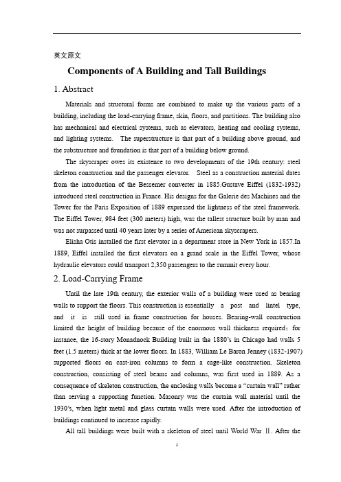
英文原文Components of A Building and Tall Buildings1. AbstractMaterials and structural forms are combined to make up the various parts of a building, including the load-carrying frame, skin, floors, and partitions. The building also has mechanical and electrical systems, such as elevators, heating and cooling systems, and lighting systems. The superstructure is that part of a building above ground, and the substructure and foundation is that part of a building below ground.The skyscraper owes its existence to two developments of the 19th century: steel skeleton construction and the passenger elevator. Steel as a construction material dates from the introduction of the Bessemer converter in 1885.Gustave Eiffel (1832-1932) introduced steel construction in France. His designs for the Galerie des Machines and the Tower for the Paris Exposition of 1889 expressed the lightness of the steel framework. The Eiffel Tower, 984 feet (300 meters) high, was the tallest structure built by man and was not surpassed until 40 years later by a series of American skyscrapers.Elisha Otis installed the first elevator in a department store in New York in 1857.In 1889, Eiffel installed the first elevators on a grand scale in the Eiffel Tower, whose hydraulic elevators could transport 2,350 passengers to the summit every hour.2. Load-Carrying FrameUntil the late 19th century, the exterior walls of a building were used as bearing walls to support the floors. This construction is essentially a post and lintel type, and it is still used in frame construction for houses. Bearing-wall construction limited the height of building because of the enormous wall thickness required;for instance, the 16-story Monadnock Building built in the 1880’s in Chicago had walls 5 feet (1.5 meters) thick at the lower floors. In 1883, William Le Baron Jenney (1832-1907) supported floors on cast-iron columns to form a cage-like construction. Skeleton construction, consisting of steel beams and columns, was first used in 1889. As a consequence of skeleton construction, the enclosing walls become a “curtain wall” rather than serving a supporting function. Masonry was the curtain wall material until the 1930’s, when light metal and glass curtain walls wer e used. After the introduction of buildings continued to increase rapidly.All tall buildings were built with a skeleton of steel until World War Ⅱ. After thewar, the shortage of steel and the improved quality of concrete led to tall building being built of reinforced concrete. Marina Tower (1962) in Chicago is the tallest concrete building in the United States;its height—588 feet (179 meters)—is exceeded by the 650-foot (198-meter) Post Office Tower in London and by other towers.A change in attitude about skyscraper construction has brought a return to the use of the bearing wall. In New York City, the Columbia Broadcasting System Building, designed by Eero Saarinen in 1962,has a perimeter wall consisting of 5-foot (1.5meter) wide concrete columns spaced 10 feet (3 meters) from column center to center. This perimeter wall, in effect, constitutes a bearing wall. One reason for this trend is that stiffness against the action of wind can be economically obtained by using the walls of the building as a tube;the World Trade Center building is another example of this tube approach. In contrast, rigid frames or vertical trusses are usually provided to give lateral stability.3. SkinThe skin of a building consists of both transparent elements (windows) and opaque elements (walls). Windows are traditionally glass, although plastics are being used, especially in schools where breakage creates a maintenance problem. The wall elements, which are used to cover the structure and are supported by it, are built of a variety of materials: brick, precast concrete, stone, opaque glass, plastics, steel, and aluminum. Wood is used mainly in house construction;it is not generally used for commercial, industrial, or public building because of the fire hazard.4. FloorsThe construction of the floors in a building depends on the basic structural frame that is used. In steel skeleton construction, floors are either slabs of concrete resting on steel beams or a deck consisting of corrugated steel with a concrete topping. In concrete construction, the floors are either slabs of concrete on concrete beams or a series of closely spaced concrete beams (ribs) in two directions topped with a thin concrete slab, giving the appearance of a waffle on its underside. The kind of floor that is used depends on the span between supporting columns or walls and the function of the space. In an apartment building, for instance, where walls and columns are spaced at 12 to 18 feet (3.7 to 5.5 meters), the most popular construction is a solid concrete slab with no beams. The underside of the slab serves as the ceiling for the space below it. Corrugated steel decks are often used in office buildings because the corrugations, when enclosed by another sheet of metal, form ducts for telephone and electrical lines.5. Mechanical and Electrical SystemsA modern building not only contains the space for which it is intended (office, classroom, apartment) but also contains ancillary space for mechanical and electrical systems that help to provide a comfortable environment. These ancillary spaces in a skyscraper office building may constitute 25% of the total building area. The importance of heating, ventilating, electrical, and plumbing systems in an office building is shown by the fact that 40% of the construction budget is allocated to them. Because of the increased use of sealed building with windows that cannot be opened, elaborate mechanical systems are provided for ventilation and air conditioning. Ducts and pipes carry fresh air from central fan rooms and air conditioning machinery. The ceiling, which is suspended below the upper floor construction, conceals the ductwork and contains the lighting units. Electrical wiring for power and for telephone communication may also be located in this ceiling space or may be buried in the floor construction in pipes or conduits.There have been attempts to incorporate the mechanical and electrical systems into the architecture of building by frankly expressing them;for example, the American Republic Insurance Company Building(1965) in Des Moines, Iowa, exposes both the ducts and the floor structure in an organized and elegant pattern and dispenses with the suspended ceiling. This type of approach makes it possible to reduce the cost of the building and permits innovations, such as in the span of the structure.6. Soils and FoundationsAll building are supported on the ground, and therefore the nature of the soil becomes an extremely important consideration in the design of any building. The design of a foundation dependson many soil factors, such as type of soil, soil stratification, thickness of soil lavers and their compaction, and groundwater conditions. Soils rarely have a single composition;they generally are mixtures in layers of varying thickness. For evaluation, soils are graded according to particle size, which increases from silt to clay to sand to gravel to rock. In general, the larger particle soils will support heavier loads than the smaller ones. The hardest rock can support loads up to 100 tons per square foot(976.5 metric tons/sq meter), but the softest silt can support a load of only 0.25 ton per square foot(2.44 metric tons/sq meter). All soils beneath the surface are in a state of compaction;that is, they are under a pressure that is equal to the weight of the soil column above it. Many soils (except for most sands and gavels) exhibit elasticproperties—they deform when compressed under load and rebound when the load is removed. The elasticity of soils is often time-dependent, that is, deformations of the soil occur over a length of time which may vary from minutes to years after a load is imposed. Over a period of time, a building may settle if it imposes a load on the soil greater than the natural compaction weight of the soil. Conversely, a building may heave if it imposes loads on the soil smaller than the natural compaction weight. The soil may also flow under the weight of a building;that is, it tends to be squeezed out.Due to both the compaction and flow effects, buildings tend settle. Uneven settlements, exemplified by the leaning towers in Pisa and Bologna, can have damaging effects—the building may lean, walls and partitions may crack, windows and doors may become inoperative, and, in the extreme, a building may collapse. Uniform settlements are not so serious, although extreme conditions, such as those in Mexico City, can have serious consequences. Over the past 100 years, a change in the groundwater level there has caused some buildings to settle more than 10 feet (3 meters). Because such movements can occur during and after construction, careful analysis of the behavior of soils under a building is vital.The great variability of soils has led to a variety of solutions to the foundation problem. Wherefirm soil exists close to the surface, the simplest solution is to rest columns on a small slab of concrete(spread footing). Where the soil is softer, it is necessary to spread the column load over a greater area;in this case, a continuous slab of concrete(raft or mat) under the whole building is used. In cases where the soil near the surface is unable to support the weight of the building, piles of wood, steel, or concrete are driven down to firm soil.The construction of a building proceeds naturally from the foundation up to the superstructure. The design process, however, proceeds from the roof down to the foundation (in the direction of gravity). In the past, the foundation was not subject to systematic investigation. A scientific approach to the design of foundations has been developed in the 20th century. Karl Terzaghi of the United States pioneered studies that made it possible to make accurate predictions of the behavior of foundations, using the science of soil mechanics coupled with exploration and testing procedures. Foundation failures of the past, such as the classical example of the leaning tower in Pisa, have become almost nonexistent. Foundations still are a hidden but costly part of many buildings.The early development of high-rise buildings began with structural steel framing. Reinforced concrete and stressed-skin tube systems have since been economically and competitively used in a number of structures for both residential and commercial purposes. The high-rise buildings ranging from 50 to 110 stories that are being built all over the United States are the result of innovations and development of new structural systems.Greater height entails increased column and beam sizes to make buildings more rigid so that under wind load they will not sway beyond an acceptable limit. Excessive lateral sway may causeserious recurring damage to partitions, ceilings, and other architectural details. In addition, excessive sway may cause discomfort to the occupants of the building because of their perception of such motion. Structural systems of reinforced concrete, as well as steel, take full advantage of the inherent potential stiffness of the total building and therefore do not require additional stiffening to limit the sway.中文译文建筑及高层建筑的组成1 摘要材料和结构类型是构成建筑物各方面的组成部分,这些部分包括承重结构、围护结构、楼地面和隔墙。
钢筋混凝土结构中英文对照外文翻译文献
中英文对照外文翻译(文档含英文原文和中文翻译)Reinforced ConcreteConcrete and reinforced concrete are used as building materials in every country. In many, including the United States and Canada, reinforced concrete is a dominant structural material in engineered construction. The universal nature of reinforced concrete construction stems from the wide availability of reinforcing bars and the constituents of concrete, gravel, sand, and cement, the relatively simple skills required in concrete construction, and the economy of reinforced concrete compared to other forms of construction. Concrete and reinforced concrete are used in bridges, buildings of all sorts underground structures, water tanks, television towers, offshore oil exploration and production structures, dams, and even in ships.Reinforced concrete structures may be cast-in-place concrete, constructed in their final location, or they may be precast concreteproduced in a factory and erected at the construction site. Concrete structures may be severe and functional in design, or the shape and layout and be whimsical and artistic. Few other building materials off the architect and engineer such versatility and scope.Concrete is strong in compression but weak in tension. As a result, cracks develop whenever loads, or restrained shrinkage of temperature changes, give rise to tensile stresses in excess of the tensile strength of the concrete. In a plain concrete beam, the moments about the neutral axis due to applied loads are resisted by an internal tension-compression couple involving tension in the concrete. Such a beam fails very suddenly and completely when the first crack forms. In a reinforced concrete beam, steel bars are embedded in the concrete in such a way that the tension forces needed for moment equilibrium after the concrete cracks can be developed in the bars.The construction of a reinforced concrete member involves building a from of mold in the shape of the member being built. The form must be strong enough to support both the weight and hydrostatic pressure of the wet concrete, and any forces applied to it by workers, concrete buggies, wind, and so on. The reinforcement is placed in this form and held in place during the concreting operation. After the concrete has hardened, the forms are removed. As the forms are removed, props of shores are installed to support the weight of the concrete until it has reached sufficient strength to support the loads by itself.The designer must proportion a concrete member for adequate strength to resist the loads and adequate stiffness to prevent excessive deflections. In beam must be proportioned so that it can be constructed. For example, the reinforcement must be detailed so that it can be assembled in the field, and since the concrete is placed in the form after the reinforcement is in place, the concrete must be able to flow around, between, and past the reinforcement to fill all parts of the form completely.The choice of whether a structure should be built of concrete, steel, masonry, or timber depends on the availability of materials and on a number of value decisions. The choice of structural system is made by the architect of engineer early in the design, based on the following considerations:1. Economy. Frequently, the foremost consideration is the overall const of the structure. This is, of course, a function of the costs of the materials and the labor necessary to erect them. Frequently, however, the overall cost is affected as much or more by the overall construction time since the contractor and owner must borrow or otherwise allocate money to carry out the construction and will not receive a return on this investment until the building is ready for occupancy. In a typical large apartment of commercial project, the cost of construction financing will be a significant fraction of the total cost. As a result, financial savings due to rapid construction may more than offset increased material costs. For this reason, any measures the designer can take to standardize the design and forming will generally pay off in reduced overall costs.In many cases the long-term economy of the structure may be more important than the first cost. As a result, maintenance and durability are important consideration.2. Suitability of material for architectural and structural function.A reinforced concrete system frequently allows the designer to combine the architectural and structural functions. Concrete has the advantage that it is placed in a plastic condition and is given the desired shape and texture by means of the forms and the finishing techniques. This allows such elements ad flat plates or other types of slabs to serve as load-bearing elements while providing the finished floor and / or ceiling surfaces. Similarly, reinforced concrete walls can provide architecturally attractive surfaces in addition to having the ability to resist gravity, wind, or seismic loads. Finally, the choice of size of shape is governed by the designer and not by the availability of standard manufactured members.3. Fire resistance. The structure in a building must withstand the effects of a fire and remain standing while the building is evacuated and the fire is extinguished. A concrete building inherently has a 1- to 3-hour fire rating without special fireproofing or other details. Structural steel or timber buildings must be fireproofed to attain similar fire ratings.4. Low maintenance.Concrete members inherently require less maintenance than do structural steel or timber members. This is particularly true if dense, air-entrained concrete has been used forsurfaces exposed to the atmosphere, and if care has been taken in the design to provide adequate drainage off and away from the structure. Special precautions must be taken for concrete exposed to salts such as deicing chemicals.5. Availability of materials. Sand, gravel, cement, and concrete mixing facilities are very widely available, and reinforcing steel can be transported to most job sites more easily than can structural steel. As a result, reinforced concrete is frequently used in remote areas.On the other hand, there are a number of factors that may cause one to select a material other than reinforced concrete. These include:1. Low tensile strength.The tensile strength concrete is much lower than its compressive strength ( about 1/10 ), and hence concrete is subject to cracking. In structural uses this is overcome by using reinforcement to carry tensile forces and limit crack widths to within acceptable values. Unless care is taken in design and construction, however, these cracks may be unsightly or may allow penetration of water. When this occurs, water or chemicals such as road deicing salts may cause deterioration or staining of the concrete. Special design details are required in such cases. In the case of water-retaining structures, special details and / of prestressing are required to prevent leakage.2. Forms and shoring. The construction of a cast-in-place structure involves three steps not encountered in the construction of steel or timber structures. These are ( a ) the construction of the forms, ( b ) the removal of these forms, and (c) propping or shoring the new concrete to support its weight until its strength is adequate. Each of these steps involves labor and / or materials, which are not necessary with other forms of construction.3. Relatively low strength per unit of weight for volume.The compressive strength of concrete is roughly 5 to 10% that of steel, while its unit density is roughly 30% that of steel. As a result, a concrete structure requires a larger volume and a greater weight of material than does a comparable steel structure. As a result, long-span structures are often built from steel.4. Time-dependent volume changes. Both concrete and steel undergo-approximately the same amount of thermal expansion and contraction. Because there is less mass of steel to be heated or cooled,and because steel is a better concrete, a steel structure is generally affected by temperature changes to a greater extent than is a concrete structure. On the other hand, concrete undergoes frying shrinkage, which, if restrained, may cause deflections or cracking. Furthermore, deflections will tend to increase with time, possibly doubling, due to creep of the concrete under sustained loads.In almost every branch of civil engineering and architecture extensive use is made of reinforced concrete for structures and foundations. Engineers and architects requires basic knowledge of reinforced concrete design throughout their professional careers. Much of this text is directly concerned with the behavior and proportioning of components that make up typical reinforced concrete structures-beams, columns, and slabs. Once the behavior of these individual elements is understood, the designer will have the background to analyze and design a wide range of complex structures, such as foundations, buildings, and bridges, composed of these elements.Since reinforced concrete is a no homogeneous material that creeps, shrinks, and cracks, its stresses cannot be accurately predicted by the traditional equations derived in a course in strength of materials for homogeneous elastic materials. Much of reinforced concrete design in therefore empirical, i.e., design equations and design methods are based on experimental and time-proved results instead of being derived exclusively from theoretical formulations.A thorough understanding of the behavior of reinforced concrete will allow the designer to convert an otherwise brittle material into tough ductile structural elements and thereby take advantage of concrete’s desirable characteristics, its high compressive strength, its fire resistance, and its durability.Concrete, a stone like material, is made by mixing cement, water, fine aggregate ( often sand ), coarse aggregate, and frequently other additives ( that modify properties ) into a workable mixture. In its unhardened or plastic state, concrete can be placed in forms to produce a large variety of structural elements. Although the hardened concrete by itself, i.e., without any reinforcement, is strong in compression, it lacks tensile strength and therefore cracks easily. Because unreinforced concrete is brittle, it cannot undergo large deformations under load and failssuddenly-without warning. The addition fo steel reinforcement to the concrete reduces the negative effects of its two principal inherent weaknesses, its susceptibility to cracking and its brittleness. When the reinforcement is strongly bonded to the concrete, a strong, stiff, and ductile construction material is produced. This material, called reinforced concrete, is used extensively to construct foundations, structural frames, storage takes, shell roofs, highways, walls, dams, canals, and innumerable other structures and building products. Two other characteristics of concrete that are present even when concrete is reinforced are shrinkage and creep, but the negative effects of these properties can be mitigated by careful design.A code is a set technical specifications and standards that control important details of design and construction. The purpose of codes it produce structures so that the public will be protected from poor of inadequate and construction.Two types f coeds exist. One type, called a structural code, is originated and controlled by specialists who are concerned with the proper use of a specific material or who are involved with the safe design of a particular class of structures.The second type of code, called a building code, is established to cover construction in a given region, often a city or a state. The objective of a building code is also to protect the public by accounting for the influence of the local environmental conditions on construction. For example, local authorities may specify additional provisions to account for such regional conditions as earthquake, heavy snow, or tornados. National structural codes genrally are incorporated into local building codes.The American Concrete Institute ( ACI ) Building Code covering the design of reinforced concrete buildings. It contains provisions covering all aspects of reinforced concrete manufacture, design, and construction. It includes specifications on quality of materials, details on mixing and placing concrete, design assumptions for the analysis of continuous structures, and equations for proportioning members for design forces.All structures must be proportioned so they will not fail or deform excessively under any possible condition of service. Therefore it is important that an engineer use great care in anticipating all the probableloads to which a structure will be subjected during its lifetime.Although the design of most members is controlled typically by dead and live load acting simultaneously, consideration must also be given to the forces produced by wind, impact, shrinkage, temperature change, creep and support settlements, earthquake, and so forth.The load associated with the weight of the structure itself and its permanent components is called the dead load. The dead load of concrete members, which is substantial, should never be neglected in design computations. The exact magnitude of the dead load is not known accurately until members have been sized. Since some figure for the dead load must be used in computations to size the members, its magnitude must be estimated at first. After a structure has been analyzed, the members sized, and architectural details completed, the dead load can be computed more accurately. If the computed dead load is approximately equal to the initial estimate of its value ( or slightly less ), the design is complete, but if a significant difference exists between the computed and estimated values of dead weight, the computations should be revised using an improved value of dead load. An accurate estimate of dead load is particularly important when spans are long, say over 75 ft ( 22.9 m ), because dead load constitutes a major portion of the design load.Live loads associated with building use are specific items of equipment and occupants in a certain area of a building, building codes specify values of uniform live for which members are to be designed.After the structure has been sized for vertical load, it is checked for wind in combination with dead and live load as specified in the code. Wind loads do not usually control the size of members in building less than 16 to 18 stories, but for tall buildings wind loads become significant and cause large forces to develop in the structures. Under these conditions economy can be achieved only by selecting a structural system that is able to transfer horizontal loads into the ground efficiently.钢筋混凝土在每一个国家,混凝土及钢筋混凝土都被用来作为建筑材料。
建筑结构设计的创新与应用(英文中文双语版优质文档)
建筑结构设计的创新与应用(英文中文双语版优质文档)With the continuous advancement of science and technology, architectural structure design is also constantly innovating and applying. Architectural structure design is a very important part of architectural design, which determines the shape and performance of the building. This paper will introduce the innovation and application of architectural structure design from various aspects.1. Structural design of suspended buildingsSuspended buildings refer to buildings that are mainly suspended from support points to maintain balance. The design of suspended buildings puts forward higher requirements for the design of building structures. In the structural design of suspended buildings, factors such as the weight of the building itself, wind loads, and earthquake loads need to be considered. At the same time, since the construction process of the suspended building requires hoisting, the safety of hoisting also needs to be considered. In order to solve these problems, architects and structural engineers have carried out a lot of exploration and research in the structural design of suspended buildings, and achieved many innovative results.2. Application of steel structureSteel structure is an important type of building structure, which has the advantages of high strength, good rigidity, and short construction period. In recent years, steel structures have been widely used in architectural design, especially in large buildings such as gymnasiums and exhibition halls. The application of steel structure not only improves the performance of the building, but also endows the building with a new shape. For example, architects have used steel structures to create stadiums like bird's nests and buildings like sailboats.3. Modular structure designModular structure refers to dividing the building into several modules, which are prefabricated in the factory and then assembled on site. The application of modular structure can greatly shorten the construction period, improve construction efficiency, and reduce the cost of construction. In the design of the modular structure, factors such as the connection mode between the modules, as well as the weight and size of the modules need to be considered. Architects and structural engineers use a variety of connection methods and materials, such as bolted connections, welding, bonding, etc., in the design of modular structures.4. Application of Building Information Modeling (BIM)Building Information Modeling is a comprehensive approach to digitize the building design and construction process. Through BIM technology, architects and structural engineers can design, optimize and simulate building structures on computers, and update building models in real time. BIM technology not only improves design efficiency, but also reduces errors and conflicts in architectural design. In the design of building structures, BIM technology can help designers simulate the stress of buildings and improve the stability and safety of buildings. In addition, BIM technology can also play an important role in the operation and maintenance of buildings, such as predicting building energy consumption, repairing and updating building facilities, etc.5. Application of new materialsThe application of new materials has also brought great innovation to the design of building structures. For example, the application of new materials such as high-performance concrete and ultra-high-strength steel can improve the strength and stability of buildings, enabling buildings to withstand greater loads. At the same time, the application of new materials can also reduce the weight of the building and the load of the foundation, thereby reducing the cost of the building. In addition, the application of new materials can also give buildings new forms. For example, architects have used materials such as fiberglass and carbon fiber to create lightweight and transparent architectural forms.6. Intelligent structural designWith the continuous development of artificial intelligence and big data technology, intelligent structural design has become a new direction of architectural structure design. Intelligent structural design can help architects and structural engineers better predict the stress of buildings and improve the safety and stability of buildings. For example, intelligent structural design can use sensors and data acquisition technology to monitor the stress of buildings in real time and give early warning of possible safety hazards. In addition, intelligent structural design can also optimize the structural design of buildings through data simulation and optimization algorithms, and improve the performance and energy saving of buildings.To sum up, the innovation and application of architectural structure design is a very important part of architectural design. Architects and structural engineers are constantly exploring and researching to promote the progress of building structure design. In the future, with the continuous advancement of science and technology, architectural structure design will continue to be innovated and applied to create a better architectural environment for human beings.随着科技的不断进步,建筑结构设计也在不断地创新与应用。
建筑结构外文文献翻译
Architecture StructureWe have and the architects must deal with the spatial aspect of activity, physical, and symbolic needs in such a way that overall performance integrity is assured. Hence, he or she well wants to think of evolving a building environment as a total system of interacting and space forming subsystems. Is represents a complex challenge, and to meet it the architect will need a hierarchic design process that provides at least three levels of feedback thinking: schematic, preliminary, and final.Such a hierarchy is necessary if he or she is to avoid being confused , at conceptual stages of design thinking ,by the myriad detail issues that can distract attention from more basic considerations .In fact , we can say that an architect’s abili ty to distinguish the more basic form the more detailed issues is essential to his success as a designer .The object of the schematic feed back level is to generate and evaluate overall site-plan, activity-interaction, and building-configuration options .To do so the architect must be able to focus on the interaction of the basic attributes of the site context, the spatial organization, and the symbolism as determinants of physical form. This means that ,in schematic terms ,the architect may first conceive and model a building design as an organizational abstraction of essential performance-space in teractions.Then he or she may explore the overall space-form implications of the abstraction. As an actual building configuration option begins to emerge, it will be modified to include consideration for basic site conditions.At the schematic stage, it would also be helpful if the designer could visualize his or her options for achieving overall structural integrity and consider the constructive feasibility and economic of his or her scheme .But this will require that the architect and/or a consultant be able to conceptualize total-system structural options in terms of elemental detail .Such overall thinking can be easily fed back to improve the space-form scheme.At the preliminary level, the architect’s emphasis will shift to the elaboration of his or her more promising schematic design options .Here the architect’s structural needs will shift to approximate design of specific subsystem options. At this stage the total structural scheme is developed to a middle level of specificity by focusing on identification and design of major subsystems to the extent that their key geometric, component, and interactive properties are established .Basic subsystem interaction and design conflicts can thus be identified and resolved in the context of total-system objectives. Consultants can play a significant part in this effort; these preliminary-level decisions may also result in feedback that calls for refinement or even major change in schematic concepts.When the designer and the client are satisfied with the feasibility of a design proposal at thepreliminary level, it means that the basic problems of overall design are solved and details are not likely to produce major change .The focus shifts again ,and the design process moves into the final level .At this stage the emphasis will be on the detailed development of all subsystem specifics . Here the role of specialists from various fields, including structural engineering, is much larger, since all detail of the preliminary design must be worked out. Decisions made at this level may produce feedback into Level II that will result in changes. However, if Levels I and II are handled with insight, the relationship between the overall decisions, made at the schematic and preliminary levels, and the specifics of the final level should be such that gross redesign is not in question, Rather, the entire process should be one of moving in an evolutionary fashion from creation and refinement (or modification) of the more general properties of a total-system design concept, to the fleshing out of requisite elements and details.To summarize: At Level I, the architect must first establish, in conceptual terms, the overall space-form feasibility of basic schematic options. At this stage, collaboration with specialists can be helpful, but only if in the form of overall thinking. At Level II, the architect must be able to identify the major subsystem requirements implied by the scheme and substantial their interactive feasibility by approximating key component properties .That is, the properties of major subsystems need be worked out only in sufficient depth to very the inherent compatibility of their basic form-related and behavioral interaction . This will mean a somewhat more specific form of collaboration with specialists then that in level I .At level III ,the architect and the specific form of collaboration with specialists then that providing for all of the elemental design specifics required to produce biddable construction documents .Of course this success comes from the development of the Structural Material.1.Reinforced ConcretePlain concrete is formed from a hardened mixture of cement ,water ,fine aggregate, coarse aggregate (crushed stone or gravel),air, and often other admixtures. The plastic mix is placed and consolidated in the formwork, then cured to facilitate the acceleration of the chemical hydration reaction lf the cement/water mix, resulting in hardened concrete. The finished product has high compressive strength, and low resistance to tension, such that its tensile strength is approximately one tenth lf its compressive strength. Consequently, tensile and shear reinforcement in the tensile regions of sections has to be provided to compensate for the weak tension regions in the reinforced concrete element.It is this deviation in the composition of a reinforces concrete section from the homogeneity of standard wood or steel sections that requires a modified approach to the basic principles of structural design. The two components of the heterogeneous reinforced concrete section are to be so arranged and proportioned that optimal use is made of the materials involved. This is possiblebecause concrete can easily be given any desired shape by placing and compacting the wet mixture of the constituent ingredients are properly proportioned, the finished product becomes strong, durable, and, in combination with the reinforcing bars, adaptable for use as main members of any structural system.The techniques necessary for placing concrete depend on the type of member to be cast: that is, whether it is a column, a bean, a wall, a slab, a foundation. a mass columns, or an extension of previously placed and hardened concrete. For beams, columns, and walls, the forms should be well oiled after cleaning them, and the reinforcement should be cleared of rust and other harmful materials. In foundations, the earth should be compacted and thoroughly moistened to about 6 in. in depth to avoid absorption of the moisture present in the wet concrete. Concrete should always be placed in horizontal layers which are compacted by means of high frequency power-driven vibrators of either the immersion or external type, as the case requires, unless it is placed by pumping. It must be kept in mind, however, that over vibration can be harmful since it could cause segregation of the aggregate and bleeding of the concrete.Hydration of the cement takes place in the presence of moisture at temperatures above 50°F. It is necessary to maintain such a condition in order that the chemical hydration reaction can take place. If drying is too rapid, surface cracking takes place. This would result in reduction of concrete strength due to cracking as well as the failure to attain full chemical hydration.It is clear that a large number of parameters have to be dealt with in proportioning a reinforced concrete element, such as geometrical width, depth, area of reinforcement, steel strain, concrete strain, steel stress, and so on. Consequently, trial and adjustment is necessary in the choice of concrete sections, with assumptions based on conditions at site, availability of the constituent materials, particular demands of the owners, architectural and headroom requirements, the applicable codes, and environmental reinforced concrete is often a site-constructed composite, in contrast to the standard mill-fabricated beam and column sections in steel structures.A trial section has to be chosen for each critical location in a structural system. The trial section has to be analyzed to determine if its nominal resisting strength is adequate to carry the applied factored load. Since more than one trial is often necessary to arrive at the required section, the first design input step generates into a series of trial-and-adjustment analyses.The trial-and –adjustment procedures for the choice of a concrete section lead to the convergence of analysis and design. Hence every design is an analysis once a trial section is chosen. The availability of handbooks, charts, and personal computers and programs supports this approach as a more efficient, compact, and speedy instructional method compared with the traditional approach of treating the analysis of reinforced concrete separately from pure design.2. EarthworkBecause earthmoving methods and costs change more quickly than those in any other branch of civil engineering, this is a field where there are real opportunities for the enthusiast. In 1935 most of the methods now in use for carrying and excavating earth with rubber-tyred equipment did not exist. Most earth was moved by narrow rail track, now relatively rare, and the main methods of excavation, with face shovel, backacter, or dragline or grab, though they are still widely used are only a few of the many current methods. To keep his knowledge of earthmoving equipment up to date an engineer must therefore spend tine studying modern machines. Generally the only reliable up-to-date information on excavators, loaders and transport is obtainable from the makers.Earthworks or earthmoving means cutting into ground where its surface is too high ( cuts ), and dumping the earth in other places where the surface is too low ( fills). Toreduce earthwork costs, the volume of the fills should be equal to the volume of the cuts and wherever possible the cuts should be placednear to fills of equal volume so as to reduce transport and double handlingof the fill. This work of earthwork design falls on the engineer who lays out the road since it is the layout of the earthwork more than anything else which decides its cheapness. From the available maps ahd levels, the engineering must try to reach as many decisions as possible in the drawing office by drawing cross sections of the earthwork. On the site when further information becomes available he can make changes in jis sections and layout,but the drawing lffice work will not have been lost. It will have helped him to reach the best solution in the shortest time.The cheapest way of moving earth is to take it directly out of the cut and drop it as fill with the same machine. This is not always possible, but when it canbe done it is ideal, being both quick and cheap. Draglines, bulldozers and face shovels an do this. The largest radius is obtained with the dragline,and the largest tonnage of earth is moved by the bulldozer, though only over short distances.The disadvantages of the dragline are that it must dig below itself, it cannot dig with force into compacted material, it cannot dig on steep slopws, and its dumping and digging are not accurate.Face shovels are between bulldozers and draglines, having a larger radius of action than bulldozers but less than draglines. They are anle to dig into a vertical cliff face in a way which would be dangerous tor a bulldozer operator and impossible for a dragline. Each piece of equipment should be level of their tracks and for deep digs in compact material a backacter is most useful, but its dumping radius is considerably less than that of the same escavator fitted with a face shovel.Rubber-tyred bowl scrapers are indispensable for fairly level digging where the distance of transport is too much tor a dragline or face shovel. They can dig the material deeply ( but only below themselves ) to a fairly flat surface, carry it hundreds of meters if need be, then drop it and level it roughly during the dumping. For hard digging it is often found economical to keep a pusher tractor ( wheeled or tracked ) on the digging site, to push each scraper as it returns to dig. As soon as the scraper is full,the pusher tractor returns to the beginning of the dig to heop to help the nestscraper.Bowl scrapers are often extremely powerful machines;many makers build scrapers of 8 cubic meters struck capacity, which carry 10 m ³ heaped. The largest self-propelled scrapers are of 19 m ³struck capacity ( 25 m ³ heaped )and they are driven by a tractor engine of 430 horse-powers.Dumpers are probably the commonest rubber-tyred transport since they can also conveniently be used for carrying concrete or other building materials. Dumpers have the earth container over the front axle on large rubber-tyred wheels, and the container tips forwards on most types, though in articulated dumpers the direction of tip can be widely varied. The smallest dumpers have a capacity of about 0.5 m ³, and the largest standard types are of about 4.5 m ³. Special types include the self-loading dumper of up to 4 m ³ and the articulated type of about 0.5 m ³. The distinction between dumpers and dump trucks must be remembered .dumpers tip forwards and the driver sits behind the load. Dump trucks are heavy, strengthened tipping lorries, the driver travels in front lf the load and the load is dumped behind him, so they are sometimes called rear-dump trucks.3.Safety of StructuresThe principal scope of specifications is to provide general principles and computational methods in order to verify safety of structures. The “ safety factor ”, which according to modern trends is independent of the nature and combination of the materials used, can usually be defined as the ratio between the conditions. This ratio is also proportional to the inverse of the probability ( risk ) of failure of the structure.Failure has to be considered not only as overall collapse of the structure but also as unserviceability or, according to a more precise. Common definition. As the reaching of a “ limit state ” which causes the construction not to accomplish the task it was designed for. There are two categories of limit state :(1)Ultimate limit sate, which corresponds to the highest value of the load-bearing capacity. Examples include local buckling or global instability of the structure; failure of some sections and subsequent transformation of the structure into a mechanism; failure by fatigue; elastic or plastic deformation or creep that cause a substantial change of the geometry of the structure; and sensitivity of the structure to alternating loads, to fire and to explosions.(2)Service limit states, which are functions of the use and durability of the structure. Examples include excessive deformations and displacements without instability; early or excessive cracks; large vibrations; and corrosion.Computational methods used to verify structures with respect to the different safety conditions can be separated into:(1)Deterministic methods, in which the main parameters are considered as nonrandom parameters.(2)Probabilistic methods, in which the main parameters are considered as random parameters.Alternatively, with respect to the different use of factors of safety, computational methods can be separated into:(1)Allowable stress method, in which the stresses computed under maximum loads are compared with the strength of the material reduced by given safety factors.(2)Limit states method, in which the structure may be proportioned on the basis of its maximum strength. This strength, as determined by rational analysis, shall not be less than that required to support a factored load equal to the sum of the factored live load and dead load ( ultimate state ).The stresses corresponding to working ( service ) conditions with unfactored live and dead loads are compared with prescribed values ( service limit state ) . From the four possible combinations of the first two and second two methods, we can obtain some useful computational methods. Generally, two combinations prevail:(1)deterministic methods, which make use of allowable stresses.(2)Probabilistic methods, which make use of limit states.The main advantage of probabilistic approaches is that, at least in theory, it is possible to scientifically take into account all random factors of safety, which are then combined to define the safety factor. probabilistic approaches depend upon :(1) Random distribution of strength of materials with respect to the conditions of fabrication and erection ( scatter of the values of mechanical properties through out the structure );(2) Uncertainty of the geometry of the cross-section sand of the structure ( faults and imperfections due to fabrication and erection of the structure );(3) Uncertainty of the predicted live loads and dead loads acting on the structure;(4)Uncertainty related to the approximation of the computational method used ( deviation of the actual stresses from computed stresses ).Furthermore, probabilistic theories mean that the allowable risk can be based on several factors, such as :(1) Importance of the construction and gravity of the damage by its failure;(2)Number of human lives which can be threatened by this failure;(3)Possibility and/or likelihood of repairing the structure;(4) Predicted life of the structure.All these factors are related to economic and social considerations such as:(1) Initial cost of the construction;(2) Amortization funds for the duration of the construction;(3) Cost of physical and material damage due to the failure of the construction;(4) Adverse impact on society;(5) Moral and psychological views.The definition of all these parameters, for a given safety factor, allows construction at the optimum cost. However, the difficulty of carrying out a complete probabilistic analysis has to be taken into account. For such an analysis the laws of the distribution of the live load and its induced stresses, of the scatter of mechanical properties of materials, and of the geometry of the cross-sections and the structure have to be known. Furthermore, it is difficult to interpret the interaction between the law of distribution of strength and that of stresses because both depend upon the nature of the material, on the cross-sections and upon the load acting on the structure. These practical difficulties can be overcome in two ways. The first is to apply different safety factors to the material and to the loads, without necessarily adopting the probabilistic criterion. The second is an approximate probabilistic method which introduces some simplifying assumptions ( semi-probabilistic methods ) .文献翻译建筑师必须从一种全局的角度出发去处理建筑设计中应该考虑到的实用活动,物质及象征性的需求。
建筑设计中英文对照外文翻译文献
中英文对照外文翻译文献(文档含英文原文和中文翻译)原文:Housing Problems and Options for the Elderly 1. IntroductionHousing is a critical element in the lives of older persons. The affordability of housing affects the ability of the elderly to afford other necessities of life such as food and medical care. Housing that is located near hospitals and doctors, shopping, transportation, and recreational facilities can facilitate access to services that can enhance the quality of life. Housing can also be a place of memories of the past and a connection to friends and neighbors. Housing with supportive features and access to services can also make it possible for persons to age in place. In this session, we will be examining housing problems andoptions for the elderly. Along the way, we will be testing your housing IQ with a series of questions and exercises.2. Housing Situation of Older PersonsHow typical is the housing situation of the olders?We will begin by examining five areas :(1)Prevalence of home ownership (2)Length of stay in current residence (3)Living arrangements (4)Attachments of older persons to where they live (5)Moving behavior.With whom older persons live can influence housing affordability, space needs, and the ability to age in place. About 54% of older persons live with their spouses, 31% live alone, almost 13% live with related persons other than their spouse and about 2% live with unrelated persons. With increasing age, older persons (primarily women) are more likely to live alone or with a relative other than a spouse. Frail older women living alone are the persons most likely to reside in homes with ‘extra’ rooms and to need both physically supportive housing features and services to "age in place". This segment of the population is also the group most likely to move to more supportive housing settings such as assisted living.Many older persons have strong psychological attachments to their homes related to length of residence. The home often represents the place where they raised their children and a lifetime of memories. It is also a connection to an array of familiar persons such as neighbors and shopkeepers as well as near by places including houses of worship, libraries and community services. For manyolder persons, the home is an extension of their own personalities which is found in the furnishings . In addition, the home can represent a sense of economic security for the future, especially for homeowners who have paid off their mortgages. For owners, the home is usually their most valuable financial asset. The home also symbolizes a sense of independence in that the resident is able to live on his or her own. For these types of reasons, it is understandable that in response to a question about housing preferences, AARP surveys of older persons continue to find that approximately 80% of older persons report that what they want is to "stay in their own homes and never move." This phenomena has been termed the preference to "age in place."Although most older persons move near their current communities, some seek retirement communities in places with warmer weather in the southwest, far west and the south.3. The Federal Government's Housing Programs for the ElderlyThe federal government has had two basic housing strategies to address housing problems of the elderly. One strategy, termed the "supply side" approach, seeks to build new housing complexes such as public housing and Section 202 housing for older persons. Public housing is administered by quasi-governmental local public housing authorities. Section 202 Housing for the elderly and disabled is sponsored by non-profit organizations including religious and non-sectarian organizations. Approximately 1.5 million olderpersons or 3% of the elderly population live in federally assisted housing, with about 387,000 living in Section 202 housing. Over time, the government has shifted away from such new construction programs because of the cost of such housing, the problems that a number of non-elderly housing programs have experienced, and a philosophy that the government should no longer be directly involved with the building of housing. Section 202 housing, a very popular and successful program, is one of the few supply-side programs funded by the federal government, although the budget allocation during the last ten years has allowed for the construction of only about 6,000 units per year compared to a high of almost 20,000 units in the late 1970s. Instead of funding new construction, federal housing initiatives over the last decade have emphasized ‘demand side’ subsidies that provide low-income renters with a certificate or a voucher that they can use in a variety of multiunit settings, including apartments in the private sector that meet rental and condition guidelines. These vouchers and certificates are aimed at reducing excessive housing costs. Some certificates are termed ‘project based’ subsidies and are tied to federally subsidized housing such as Section 202. Because housing programs are not an entitlement, however, supply-side and demand side programs together are only able to meet the needs of about 1/3 of elderly renters who qualify on the basis of income.While advocates for housing have been trying to hold on to the existing programs in the face of huge budget cuts at HUD, much of the attention has been shifting towards meeting the shelter and service needs of the frail elderly. This emphasis reflects the increasing number of older persons in their eightiesand nineties who need a physically supportive environment linked with services. This group of older persons includes a high percentage of older residents of public and Section 202 housing. Initially built for independent older persons who were initially in the late sixties and early seventies, this type of housing now includes older persons in their eighties and nineties, many of whom have aged in place. Consequently, the government is faced with creating strategies to bring services into these buildings and retrofit them to better suit the needs of frail older persons. A major initiative of the early 1990s, which may be stalled by current budget problems at HUD, has been for the federal government to pay for service coordinators to assess the needs of residents of government assisted housing complexes and link them with services. As of 1998, there were approximately 1,000 service coordinators attached to government assisted housing complexes across the country.4. The Housing Continuum: A Range of Options for ElderlyA long-standing assumption in the field of housing has been that as persons become more frail, they will have to move along a housing continuum from one setting to another. As the figure on housing options suggests, along this continuum are found a range of housing options including single family homes, apartments, congregate living, assisted living, and board and care homes (Kendig & Pynoos, 1996). The end point of the housing continuum has been thenursing home. These options vary considerably in terms of their availability, affordability, and ability to meet the needs of very frail older persons.The concept of a continuum of supportive care is based on the assumption that housing options can be differentiated by the amount and types of services offered; the supportiveness of the physical setting in terms of accessibility, features, and design; and the competency level of the persons to whom the housing is targeted. The figure on housing options indicates how such options generally meet the needs of older persons who are categorized,as independent, semi-dependent and dependent. Semi-dependent older persons can be thought of as needing some assistance from other persons with instrumental activities of daily living (IADLs) such as cooking, cleaning, and shopping. In addition to needing assistance with some IADLs, dependent older persons may require assistance with more basic activities such as toileting, eating and bathing. Although semi-dependent and dependent older persons can be found throughout the housing continuum, independent older persons are very unlikely to reside in housing types such as assisted living specifically designed and equipped to meet the needs of frail older persons unless their spouses require these needs.Although the continuum of housing identifies a range of housing types, there is increasing recognition that frail older persons do not necessarily have to move from one setting to another if they need assistance. Semi-dependent or dependent older persons can live in a variety of settings, including their own homes and apartments, if the physical environment is made more supportive, caregivers are available to provide assistance and affordable services areaccessible.5. ConclusionsHousing plays a critical role in the lives of older persons. Most older homeowners who function independently express a high level of satisfaction with their dwelling units. However, high housing costs, especially for renters, remain a financial burden for many older persons and problems associated with housing condition persist especially for low- income renters and persons living in rural areas. Federal housing programs such as public housing, Section 202 housing, and Section 8 housing certificates have only been able to address the basic housing problems of only about one-third of eligible older persons because of limited budgets. Moreover, a shortage of viable residential options exists for frail older persons. Up until the last decade, housing for the elderly was conceived of primarily as shelter. It has become increasingly recognized that frail older persons who needed services and physically supportive features often had to move from their homes or apartments to settings such as board and care or nursing homes to receive assistance. Over time, however, the concept of a variety of housing types that can be linked has replaced the original idea of the continuum of housing. It is possible for frail older persons to live in a variety of existing residential settings, including their own homes and apartments with the addition of services and home modifications. Consequently, the last decade has seen a number of efforts to modify homes, add service coordinators to multi-unit housing and create options such as accessory and ECHO units. Although thesestrategies have been enhanced by a somewhat greater availability of home care services, Medicaid policy still provides incentives to house frail older persons in nursing homes. The most visible development in the field of housing for frail older persons has been the growth of private sector assisted living which is now viewed by many state governments as a residential alternative to nursing homes. The AL movement itself has raised a number of regulatory and financing issues that cross-cut housing and long term care such as what constitutes a residential environment, insuring that residents can age in place, accommodating resident preferences, protecting the rights of individuals and insuring quality of care. Nevertheless, the emergence of AL along with a wider range of other housing options holds out the promise that older persons will have a larger range of choices among living arrangements.译文:老年人的住宅问题与选择一、简介住宅在老年人生活的极为重要。
建筑类外文文献及中文翻译资料讲解
forced concrete structure reinforced with anoverviewReinSince the reform and opening up, with the national economy's rapid and sustained development of a reinforced concrete structure built, reinforced with the development of technology has been great. Therefore, to promote the use of advanced technology reinforced connecting to improve project quality and speed up the pace of construction, improve labor productivity, reduce costs, and is of great significance.Reinforced steel bars connecting technologies can be divided into two broad categories linking welding machinery and steel. There are six types of welding steel welding methods, and some apply to the prefabricated plant, and some apply to the construction site, some of both apply. There are three types of machinery commonly used reinforcement linking method primarily applicable to the construction site. Ways has its own characteristics and different application, and in the continuous development and improvement. In actual production, should be based on specific conditions of work, working environment and technical requirements, the choice of suitable methods to achieve the best overall efficiency.1、steel mechanical link1.1 radial squeeze linkWill be a steel sleeve in two sets to the highly-reinforced Department with superhigh pressure hydraulic equipment (squeeze tongs) along steel sleeve radial squeeze steel casing, in squeezing out tongs squeeze pressure role of a steel sleeve plasticity deformation closely integrated with reinforced through reinforced steel sleeve and Wang Liang's Position will be two solid steel bars linkedCharacteristic: Connect intensity to be high, performance reliable, can bear high stress draw and pigeonhole the load and tired load repeatedly.Easy and simple to handle, construction fast, save energy and material, comprehensive economy profitable, this method has been already a large amount of application in the project.Applicable scope : Suitable for Ⅱ, Ⅲ, Ⅳgrade reinforcing bar (including welding bad reinfor cing bar ) with ribbing of Ф 18- 50mm, connection between the same diameter or different diameters reinforcing bar .1.2must squeeze linkExtruders used in the covers, reinforced axis along the cold metal sleeve squeeze dedicated to insert sleeve Lane two hot rolling steel drums into a highly integrated mechanical linking methods.Characteristic: Easy to operate and joining fast and not having flame homework , can construct for 24 hours , save a large number of reinforcing bars and energy. Applicable scope : Suitable for , set up according to first and second class antidetonation requirement -proof armored concrete structure ФⅡ, Ⅲgrade reinforcing bar with ribbing of hot rolling of 20- 32mm join and construct live.1.3 cone thread connectingUsing cone thread to bear pulled, pressed both effort and self-locking nature, undergo good principles will be reinforced by linking into cone-processing thread at the moment the value of integration into the joints connecting steel bars.Characteristic: Simple , all right preparatory cut of the craft , connecting fast, concentricity is good, have pattern person who restrain from advantage reinforcing bar carbon content.Applicable scope : Suitable for the concrete structure of the industry , civil buil ding and general structures, reinforcing bar diameter is for Фfor the the 16- 40mm one Ⅱ, Ⅲgrade verticality, it is the oblique to or reinforcing bars horizontal join construct live.conclusionsThese are now commonly used to connect steel synthesis methods, which links technology in the United States, Britain, Japan and other countries are widely used. There are different ways to connect their different characteristics and scope of theactual construction of production depending on the specific project choose a suitable method of connecting to achieve both energy conservation and saving time limit for a project ends.钢筋混凝土结构中钢筋连接综述改革开放以来,随着国民经济的快速、持久发展,各种钢筋混凝土建筑结构大量建造,钢筋连接技术得到很大的发展。
工程结构中英文对照外文翻译文献
中英文对照外文翻译文献(文档含英文原文和中文翻译)原文:Structure DesignAbstract: Structure design is the selection of materials and member type ,size, and configuration to carry loads in a safe and serviceable fashion .In general ,structural design implies the engineering of stationary objects such as buildings and bridges ,or objects that maybe mobile but have a rigid shape such as ship hulls and aircraft frames. Devices with parts planned to move with relation to each other(linkages) are generally assigned to the area of mechanical .Key words: Structure Design ;Structural analysis ;structural scheme ;Project requirementsStructural design involved at least five distinct phases of work: project requirements, materials, structural scheme, analysis, and design. For unusual structures or materials a six phase, testing, should be included. These phases do not proceed in a rigid progression , since different materials can be most effective in different schemes , testing can result in change to a design , and a final design is often reached by starting with a rough estimated design , then looping through several cycles of analysis and redesign . Often, several alternative designs will prove quite close in cost, strength, and serviceability. The structural engineer, owner, or end user would then make a selection based on other considerations.Project requirements. Before starting design, the structural engineer must determine the criteria for acceptable performance. The loads or forces to be resisted must be provided. For specialized structures, this may be given directly, as when supporting a known piece of machinery, or a crane of known capacity. For conventional buildings, buildings codes adopted on a municipal, county , or , state level provide minimum design requirements for live loads (occupants and furnishings , snow on roofs , and so on ). The engineer will calculate dead loads(structural and known, permanent installations ) during the design process.For the structural to be serviceable or useful , deflections must also be kept within limits ,since it is possible for safe structural to be uncomfortable “bounce”Very tight deflection limits are set on supports for machinery , since beam sag can cause drive shafts to bend , bearing to burn out , parts to misalign , and overhead cranes to stall . Limitations of sag less than span /1000 ( 1/1000 of the beam length ) are not uncommon . In conventional buildings, beams supporting ceilings often have sag limits of span /360 to avoid plaster cracking, or span /240 to avoid occupant concern (keep visual perception limited ). Beam stiffness also affects floor “bounciness,”which can be annoying if not controlled. In addition , lateral deflection , sway , or drift of tall buildings is often held within approximately height /500 (1/500 of the building height ) to minimize the likelihood of motion discomfort in occupants of upper floors on windy days .Member size limitations often have a major effect on the structural design. For example, a certain type of bridge may be unacceptable because of insufficient under clearance for river traffic, or excessive height endangering aircraft. In building design, ceiling heights and floor-to-floor heights affect the choice of floor framing. Wall thicknesses and column sizes and spacing may also affect theserviceability of various framing schemes.Materials selection. Technological advances have created many novel materials such as carbon fiber and boron fiber-reinforced composites, which have excellent strength, stiffness, and strength-to-weight properties. However, because of the high cost and difficult or unusual fabrication techniques required , they are used only in very limited and specialized applications . Glass-reinforced composites such as fiberglass are more common, but are limited to lightly loaded applications. The main materials used in structural design are more prosaic and include steel, aluminum, reinforced concrete, wood , and masonry .Structural schemes. In an actual structural, various forces are experienced by structural members , including tension , compression , flexure (bending ), shear ,and torsion (twist) . However, the structural scheme selected will influence which of these forces occurs most frequently, and this will influence the process of materials selection.Tension is the most efficient way to resist applied loads ,since the entire member cross section is acting to full capacity and bucking is not a concern . Any tension scheme must also included anchorages for the tension members . In a suspension bridge , for example ,the anchorages are usually massive dead weights at the ends of the main cables . To avoid undesirable changes in geometry under moving or varying loads , tensionschemes also generally require stiffening beams or trusses.Compression is the next most efficient method for carrying loads . The full member cross section is used ,but must be designed to avoid bucking ,either by making the member stocky or by adding supplementary bracing . Domed and arched buildings ,arch bridges and columns in buildings frames are common schemes . Arches create lateral outward thrusts which must be resisted . This can be done by designing appropriate foundations or , where the arch occurs above the roadway or floor line , by using tension members along the roadway to tie the arch ends together ,keeping them from spreading . Compression members weaken drastically when loads are not applied along the member axis , so moving , variable , and unbalanced loads must be carefully considered.Schemes based on flexure are less efficient than tension and compression ,since the flexure or bending is resisted by one side of the member acting in tension while the other side acts in compression . Flexural schemes such as beams , girders , rigid frames , and moment (bending ) connected frames have advantages in requiring no external anchorages or thrust restrains other than normal foundations ,and inherent stiffness and resistance to moving ,variable , and unbalanced loads .Trusses are an interesting hybrid of the above schemes . They are designed to resist loads by spanning in the manner of a flexural member, but act to break up the load into a series of tension and compressionforces which are resisted by individually designed tension and have excellent stiffness and resistance to moving and variable loads . Numerous member-to-member connections, supplementary compression braces ,and a somewhat cluttered appearance are truss disadvantages .Plates and shells include domes ,arched vaults ,saw tooth roofs , hyperbolic paraboloids , and saddle shapes .Such schemes attempt to direct all force along the plane of the surface ,and act largely in shear . While potentially very efficient ,such schemes have very strict limitations on geometry and are poor in resisting point ,moving , and unbalanced loads perpendicular to the surface.Stressed-skin and monologue construction uses the skin between stiffening ribs ,spars ,or columns to resist shear or axial forces . Such design is common in airframes for planes and rockets, and in ship hulls . it has also been used to advantage in buildings. Such a design is practical only when the skin is a logical part of the design and is never to be altered or removed .For bridges , short spans are commonly girders in flexure . As spans increase and girder depth becomes unwieldy , trusses are often used ,as well as cablestayed schemes .Longer spans may use arches where foundation conditions ,under clearance ,or headroom requirements are favorable .The longest spans are handled exclusively by suspension schemes ,since these minimize the crucial dead weight and can be erectedwire by wire .For buildings, short spans are handled by slabs in flexure .As spans increase, beams and girders in flexure are used . Longer spans require trusses ,especially in industrial buildings with possible hung loads . Domes ,arches , and cable-suspended and air –supported roofs can be used over convention halls and arenas to achieve clear areas .Structural analysis . Analysis of structures is required to ensure stability (static equilibrium ) ,find the member forces to be resisted ,and determine deflections . It requires that member configuration , approximate member sizes ,and elastic modulus ; linearity ; and curvature and plane sections . Various methods are used to complete the analysis .Final design .once a structural has been analyzed (by using geometry alone if the analysis is determinate , or geometry plus assumed member sizes and materials if indeterminate ), final design can proceed . Deflections and allowable stresses or ultimate strength must be checked against criteria provided either by the owner or by the governing building codes . Safety at working loads must be calculated . Several methods are available ,and the choice depends on the types of materials that will be used .Pure tension members are checked by dividing load by cross-section area .Local stresses at connections ,such as bolt holes or welds ,require special attention . Where axial tension is combined with bendingmoment ,the sum of stresses is compared to allowance levels . Allowable : stresses in compression members are dependent on the strength of material, elastic modulus ,member slenderness ,and length between bracing points . Stocky members are limited by materials strength ,while slender members are limited by elastic bucking .Design of beams can be checked by comparing a maximum bending stress to an allowable stress , which is generally controlled by the strength of the material, but may be limited if the compression side of the beam is not well braced against bucking .Design of beam-columns ,or compression members with bending moment ,must consider two items . First ,when a member is bowed due to an applied moment ,adding axial compression will cause the bow to increase .In effect ,the axial load has magnified the original moment .Second ,allowable stresses for columns and those for beams are often quite different .Members that are loaded perpendicular to their long axis, such as beams and beam-columns, also must carry shear. Shear stresses will occur in a direction to oppose the applied load and also at right angles to it to tie the various elements of the beam together. They are compared to an allowable shear stress. These procedures can also be used to design trusses, which are assemblies of tension and compression members. Lastly, deflections are checked against the project criteria using finalmember sizes.Once a satisfactory scheme has been analyzed and designed to be within project criteria, the information must be presented for fabrication and construction. This is commonly done through drawings, which indicate all basic dimensions, materials, member sizes, the anticipated loads used in design, and anticipated forces to be carried through connections.结构设计摘要:结构设计是选择材料和构件类型,大小和形状以安全有用的样式承担荷载。
建筑结构设计与预算外文翻译文献
建筑结构设计与预算外文翻译文献建筑结构设计与预算外文翻译文献(文档含中英文对照即英文原文和中文翻译)A fundamental explanation of the behaviour ofreinforced concrete beams in flexure basedon the properties of concrete under multiaxial stressM. D. KotsovosDepartment of Civil Engineering, Imperial College of Science and Technology, London (U. K.)The paper questions the validity of the generally accepted view that for a reinforced concretestructure to exhibit "ductile" behaviour under increasing load it is necessary for the stressstrain relationships of concrete to have a gradually descending post-ultimate branch.Experimental data are presented for reinforced concrete beams in bending which indicate the presence of longitudinal compressive strains on the compressive face in excess of 0.0035. It is shown that these strains, which are essential for "ductile" behaviour, are caused by acomplex multiaxial compressive state of stress below ultimate strength rather than postultimate material characteristics. The presence of a complex stress system provides a fundamental explanation for beam behaviour which does not affect existing design procedures.1. INTRODUCTIONThe "plane sections" theory not, only is generally considered to describe realistically the deformation response of reinforced and prestressed concrete beams under flexure and axial load, but is also formulated so that it provides a design tool noted for both its effectiveness and simplicity [1]. The theory describes analytically the relationship between load-carrying capacity and geometric characteristics of a beam by considering the equilibrium conditions at critical cross-sections. Compatibility of deformation is satisfied by the "plane cross-sections remain plane" assumption and the longitudinal concrete and steel stresses are evaluated by the material stress-strain characteristics. Transverse stresses and strains are ignored for the purposes of simplicity.The stress-strain characteristics of concrete in compression are considered to be adequately described by the deformational response of concrete specimens such as prisms or cylinders under uniaxial compression and the stress distribution in the compression zone of a cross-section at the ultimate limit state, as proposed by current codes of practice such as CP 110 [1], exhibits a shape similar to that shown in figure 1. The figure indicates that the longitudinal stress increases with thedistance from the neutral axis up to a maximum value and then remains constant. Such a shape of stress distribution has been arrived at on the basis of both safety considerations and the widely held view that the stress-strain relationship of concrete in compression consists of both an ascending and a gradually descending portion (seefig. 2). The portion beyond ultimate defines the post-ultimate stress capacity of the material which, Typical stress-strain relationship for concrete in compression. as indicated in figure 1, is generally considered to make a major contribution to the maximum load-carrying capacity of the beam.However, a recent analytical investigation of the behaviour of concrete under concentrations of load has indicated that the post-ultimate strength deformational response of concrete under compressive states of stress has no apparent effect on the overall behaviour of the structural forms investigated ( [2], [3]). If such behaviour is typical for any structure, then the large compressivestrains (in excess of 0.0035) measured on the top surface of a reinforced concrete beam at its ultimate limit state (see fig. 1), cannot be attributed to post-ultimate uniaxial stress-strain characteristics. Furthermore, since the compressive strain at the ultimate strength level of any concrete under uniaxial compression is of the order of 0.002 (see fig. 2), it would appear that a realistic prediction of the beam responseunder load cannot be based solely on the ascending portion of the uniaxial stress-strain relationship of concrete.In view of the above, the work described in the following appraises the widely held view that a uniaxial stress-strain relationship consisting of an ascending and a gradually descending portion is essential for the realistic description of the behaviour of a reinforced concrete beam in flexure. Results obtained from beams subjected to flexure under two-point loading indicate that the large strains exhibited by concrete in the compression zone of the beams are due to a triaxial state of stress rather than the uniaxial post-ultimate stress-strain characteristics of concrete. It is shown that the assumption that the material itself suffers a completeand immediate loss of load-carrying capacity when ultimate strength is exceeded is compatible with the observed "ductile" structural behaviour as indicated by load-deflexion or moment-rotation relationships.2. EXPERIMENTAL DETAILS2.1. SpecimensThree rectangular reinforced concrete beams of 915 mm span and 102 mm height x 51 mm width cross-section were subjected to two-point load with shear spans of 305 mm (see fig. 3). The tension reinforcement consisted of two 6 mm diameter bars with a yield load of 11.8 kN. The bars were bent back at the ends of the beams so as to provide compression reinforcement along the whole length of the shear pression and tension reinforcement along each shear span were linked by seven 3.2 mm diameter stirrups. Neither compression reinforcement nor stirrups were provided in the central portion of the beams. Due to the above reinforcement arrangement all beams failed in flexure rather than shear, although the shear span to effective depthratio was 3.The beams, together with control specimens, were cured under damp hessian at 20~ for seven days and then stored in the laboratory atmosphere (20o C~and 40% R.H.) for about 2 months, until tested. Full details of the concrete mix used are given in table I.2.2. TestingLoad was applied through a hydraulic ram and spreader beam in increments of approximately 0.5 kN. At each increment the load was maintained constant for approximately 2 minutes in order to measure the load and the deformation response of the specimens. Load was measured by using a load cell and deformation response by using both 20 mm long electrical resistance strain gauges and displacement transducers. The strain gauges were placed on the top and side surfaces of the beams in the longitud{nal and the transverse directions as shown in figure 4. The figure also indicates the position of the linear voltage displacement transducers (LVDT's) which were used to measure deflexion at mid-span and at the loaded cross-sections.The measurements were recorded by an automatic computer-based data-logger (Solatron) capable of measuring strains and displacements to a sensitivity of ± 2 microstrain and ±0.002 ram, respectively.3. EXPERIMENTAL RESULTSThe main results obtained from the experiments together with information essential for a better understanding of beam behaviour are shown in figures 5 to 14. Figure 5 shows the uniaxial compression stressstrain relationships of the concrete used in the investigation, whereas figures 6 and 7 show the relationships between longitudinal and transverse strains, measured on the top surface of the beams (a) at the cross-sections where the flexure cracks which eventually cause failure are situated (critical sections) and (b)at cross-sections within the shear span, respectively. Figures 6 and 7 also include the longitudinal straintransverse strain relationship corresponding to the stress-strain relationships of figure 5.Figure 8 shows the typical change in shape of the transverse deformation profile of the top surface of the beams with load increasing to failure and figure 9 provides a schematic representation of the radial forces and stresses developing with increasing load due to the deflected shape of the beams. Typical load-deflexion relationships of the beams are shown in figure 10, whereas figure 11 depicts the variation on critical sections of the average vertical strains measured on the side surfaces of the beams with the transverse strains measured on the top surface. Figure 12 indicates the strength and deformation response of a typical concrete under various states of triaxial stress and figure 13 presents the typical crack pattern of the beams at the moment of collapse. Finally, figure 14 shows the shape of the longitudinal stress distribution on the compressive zone of a critical section at failure predicted on the basis of the concepts discussed in the following section.翻译在多向应力作用下从混凝土的特性看受弯钢筋混凝土梁变化的一个基本试验M. D. Kotsovos 伦敦皇家科学与技术学院土木工程系本文所探讨的问题是通常认为在荷载递增下钢筋混凝土结构呈现弹性状态,这必须是因为混凝土的应力-应变关系有一个逐渐递减的临界部分的真实性。
剪力墙结构论文中英文资料外文翻译文献
中英文资料外文翻译文献一.英文原文A NEW STAGGERED SHEAR WALL STRUCTURE FOR HIGH-RISE BUILDINGABSTRACTShear wall structure has been widely used in tall buildings. However, there are still two obvious disadvantages in this structure: first of all, space between two shear wall could not too big and the plane layout is not flexible, so that serviceability requirements are dissatisfied for public buildings; secondly, the bigger dead weight will lead to the increase of constructional materials and seismic force which cause desigh difficulty of super-structures and foundations. In this paper, a new type tall building structure-staggered shear wall structure-is presented in order to overcome above disadvantages of traditional shear wall, which not only provide big space for architectural design but also has lighter dead weight and high capacity of resistance to horizontal load. REINFORCEMENT CONCRETE STAGGERED SHEAR WALL STRUCTURAL SYSTEM IN TALL BUILDINGS Structure Style and Features of New Type Shear Wall Structural System:In this new-type shear wall structural system,every shear wall is at staggered location on adjacent floor, as well as adjacent shear walls are staggered with each other.One end of floor slab is supported on top edge of one shear wall; the other end of floor slab is supported on bottom edge of adjacent shear wall. The edge column and beam are set beside every shear wall. The embedded column and connected beam are set on every floor. The advantage of this structural system is its big use space with small span floor slab.The shear wall arrangement can be staggered or not according to use requirement, shown in Figure 1. As a result, the width of one bay is increased from L to 2L or 3L. In addition, the dead weigh of staggered shear wall is smaller than that of traditional down-to-ground shear wall, so the material cost is reduced. The structural analysis result indicates the wall amount decreases by 25% and the dead weigh decreased by 20%comparing the new-type shear wall with traditional shear wall, while both have same lateral stiffness. Two main obvious disadvantages of traditional shear wall are overcome and the use space of shear wall structures is enlarged effectively. Besides the architectural convenience, the staggered shear wall has other advantages. Although the stiffness of every shear wall is changed along vertical direction, the sum stiffness of whole structure is even along vertical direction when adjacent shear walls are set on staggered locations. The whole structural deformation is basically bending style. Form the analysis of reference,the staggered shear wall has stronger whole stiffness, less top-storey displacement(decreasing by about 58%),and less relative storey displacement comparing with traditional coupled shear wall.Under the same horizontal load, the staggered shear wall structure could effectively cut down the internal force of coupled beam and embedded column, at the same time the structural seismic performance is improved.1 2Working Mechanism of New Type Shear Wall StructureUnder the vertical load, this structure effect is the same as ordinary frame-shear wall structure, that is, the shear wall and column act together to resist the vertical load. Because the stiffness of every span shear wall is large and the deformation is small, the bending deformation and moment of columns are very small. Under lateral load, the structure deformation is uniform, thereby it can improve the whole stiffness effectively and the higher capability resisting lateral load is obtained.The main cause is the particular arrangement method of walls, which could be explained as follows: firstly, the lateralshearing force transfer mechanism is different from traditional shear wall. The lateral shearing force on top edge of shear wall is transferred to under layer floor slab though the bottom edge of wall, then to under storey adjacent shear wall through the under storey floor slab. At last, the lateral shearing force is transferred to ground floor shear wall and foundation.By this way,the lateral shearing force transfer mechanism is special, in which every floor slab transfer the lateral shearing force of itself floor and above floor.But in traditional shear wall directly. This structure makes the best use of the peculiarity that the slab stiffness is very strong to transfer and resist lateral shear. Although the shear walls are not up bottom in sequence, the slabs which has larger stiffness participate in the work transferring and resisting lateral shear force from the top to the down,from the floor middle part to edge, and from the edge to middle part in whole structure.It corresponds to a space integer structure with large lateral stiffness connected all shear walls by slabs, which have been cut in every story and span. It has been proved in author’s paper that the whole structure will occur integer-bending deformation under lateral force action,while every storey shear walls will occur integer bending without local bending. Secondly, in every piece of staggered shear wall (shown in Figure 2),the shear wall arrangement forms four large X diagonal brace along adcb,cfed, ehgf, gjih (dashed as shown in Figure 2).Because the shear walls forming X diagonal brace have large stiffness and strength, the X diagonal brace stiffness is strong. In addition, both the edge beams and columns around the boundary form bracing ‘frame”with large lateral stiffness. Hence, the structural integer stiffness is greatly improved.Due to the above main reasons, this structure is considered to have particular advantages compared with traditional shear wall structure in improving structural lateral stiffness. It can provide larger using space, and reduce the material, earthquake action as well as dead weight.Also, it can provide larger lateral stiffness, which will benefit the structural lateral capability. In author’s paper and in this paper the example calculating results indicates that lateral stiffness of this structure are double of coupled shear wall structure ,and nearly equal to integer shear wall structure (light small than the latter).Aseismic analysis and construction measures in a buildingexampleIn order to study dynamic characteristics and aseismic performances in this structural system, the staggered shear wall will be used as all cross walls in the large bay shear wall structure without internal longitudinal walls.Example. Thereis a nine-storey reinforcement concrete building, which is large bay shear wall struvture, shown in figure3. here,walls columns, beams, and slabs are all cast-in-situ. The thickness t=240mm is used for shear walls from 1 to 3 stories, while thickness t=200mm is used for shear walls from 4 to 9 stories. Given the section of columns of width b=500mm and depth h=600mm . Given the section of beams of width b=300mm and depth h=700mm . The modulus of elasticity is assumed to be E=2.1*10E7kN/2m and G=1.05*10E7 kN /2m . The external longitudinal walls are cast-in-situ wall frame, and the cross walls are staggered shear walls , showm in Figure 3 (a) (scheme I) ,intensity 8 zones near earthquake, 2type site ground 。
高层建筑结构外文翻译文献
高层建筑结构外文翻译文献高层建筑结构外文翻译文献(文档含中英文对照即英文原文和中文翻译)外文:The Structure Form of High-Rise Buildings ABSTRACT:High-rise building is to point to exceed a certain height and layers multistory buildings. In the United States, 24.6 m or 7 layer above as high-rise buildings; In Japan, 31m or 8 layer and above as high-rise buildings; In Britain, to have equal to or greater than 24.3 m architecture as high-rise buildings. Since 2005 provisions in China more than 10 layers of residential buildings and more than 24 meters tall other civil building for high-rise buildings.KEYWARD:High-Rise Buildings;Shear-Wall Systems;Rigid-Frame Systems 1. High-rise building profilesAlthough the basic principles of vertical and horizontal subsystem design remain the same for low- , medium- , or high-rise buildings, when a building gets high the vertical subsystems become a controlling problem for two reasons. Higher vertical loads will require larger columns, walls, and shafts. But, more significantly, the overturning moment and the shear deflections produced by lateral forces are much larger and must be carefully provided for.The vertical subsystems in a high-rise building transmit accumulated gravity load from story to story, thus requiring larger column or wall sections to support such loading. In addition these same vertical subsystems must transmit lateral loads, such as wind or seismic loads, to the foundations. However, in contrast to vertical load, lateral load effects on buildings are not linear and increase rapidly with increase in height. For example under wind load , the overturning moment at the base of buildings varies approximately as the square of a buildings may vary as the fourth power of buildings height , other things being equal. Earthquake produces an even more pronounced effect.When the structure for a low-or medium-rise building is designed for dead and live load, it is almost an inherent property that the columns, walls, and stair or elevator shafts can carry most of the horizontal forces. The problem is primarily one of shear resistance. Moderate addition bracing for rigid frames in “short” buildings can easily be provided by filling certain panels (or even all panels) without increasing the sizes of thecolumns and girders otherwise required for vertical loads.Unfortunately, this is not is for high-rise buildings because the problem is primarily resistance to moment and deflection rather than shear alone. Special structural arrangements will often have to be made and additional structural material is always required for the columns, girders, walls, and slabs in order to made a high-rise buildings sufficiently resistant to much higher lateral deformations.As previously mentioned, the quantity of structural material required per square foot of floor of a high-rise buildings is in excess of that required for low-rise buildings. The vertical components carrying the gravity load, such as walls, columns, and shafts, will need to be strengthened over the full height of the buildings. But quantity of material required for resisting lateral forces is even more significant.With reinforced concrete, the quantity of material also increases as the number of stories increases. But here it should be noted that the increase in the weight of material added for gravity load is much more sizable than steel, whereas for wind load the increase for lateral force resistance is not that much more since the weight of a concrete buildings helps to resist overturn. On the other hand, the problem of design for earthquake forces. Additional mass in the upper floors will give rise to a greater overall lateral force under the of seismic effects.In the case of either concrete or steel design, there are certain basic principles for providing additional resistance to lateral to lateral forces and deflections in high-rise buildings without too much sacrifire in economy.(1) Increase the effective width of the moment-resisting subsystems. This is very useful because increasing the width will cut down the overturn force directly and will reduce deflection by the third power of the width increase, other things remaining cinstant. However, this does require that vertical components of the widened subsystem be suitably connected to actually gain this benefit.(2) Design subsystems such that the components are made to interact in the most efficient manner. For example, use truss systems with chords and diagonals efficiently stressed, place reinforcing for walls at critical locations, and optimize stiffness ratios for rigid frames.(3) Increase the material in the most effective resisting components. For example, materials added in the lower floors to the flanges of columns and connecting girders will directly decrease the overall deflection and increase the moment resistance without contributing mass in the upper floors where the earthquake problem is aggravated.(4) Arrange to have the greater part of vertical loads be carried directly on the primary moment-resisting components. This will help stabilize the buildings against tensile overturning forces by precompressing the major overturn-resisting components.(5) The local shear in each story can be best resisted by strategic placement if solid walls or the use of diagonal members in a vertical subsystem. Resisting these shears solely by vertical members in bending is usually less economical, since achieving sufficient bending resistance in the columns and connecting girders will require more material and construction energy than using walls or diagonal members.(6) Sufficient horizontal diaphragm action should be provided floor. This will help to bring the various resisting elements to work together instead of separately.(7) Create mega-frames by joining large vertical and horizontal components such as two or more elevator shafts at multistory intervals with a heavy floor subsystems, or by use of very deep girder trusses.Remember that all high-rise buildings are essentially vertical cantilevers which are supported at the ground. When the above principles are judiciously applied, structurally desirable schemes can be obtained by walls, cores, rigid frames, tubular construction, and other vertical subsystems to achieve horizontal strength and rigidity.2. Shear-Wall SystemsShear wall structure is reinforced concrete wallboard to replace with beam-column frame structure of, can undertake all kinds of loads, and can cause the internal force of the structure effectively control the horizontal forces with reinforced concrete wallboard, the vertical and horizontal force to bear the structure called the shear wall structure. This structure was in high-rise building aplenty, so, homebuyers can need not be blinded by its terms. Shear wall structure refers to the vertical of reinforced concrete wallboard, horizontal direction is still reinforced concrete slab of carrying the wall, so big a system, that constitutes the shear wall structure. Why call shear wall structure,actually, the higher the wind load building to its push is bigger, so the wind direction of pushing that level, such as promoting the house, below was a binding, the above the wind blows should produce certain swing floating, swing floating restrictions on the very small, vertical wallboard to resist, the wind over, wants it has a force on top, make floor do not produce swing or shift float degrees small, in particular the bounds of structure, such as: the wind from one side, then there is a considerable force board with it braved along the vertical wallboard, the height of the force, is equivalent to a pair of equivalent shearing, like a with scissors cut floor of force building and the farther down, accordingly, the shear strength of such wallboard that shear wall panels, also explains the wallboard vertical bearing of vertical force also not only should bear the horizontal wind loading, including the horizontal seismic forces to one of its push wind.When shear walls are compatible with other functional requirements, they can be economically utilized to resist lateral forces in high-rise buildings. For example, apartment buildings naturally require many separation walls. When some of these are designed to be solid, they can act as shear walls to resist lateral forces and to carry the vertical load as well. For buildings up to some 20storise, the use of shear walls is common. If given sufficient length, such walls can economically resist lateral forces up to 30 to 40 stories or more.However, shear walls can resist lateral load only the plane of the walls ( i.e.not in a diretion perpendicular to them) . Therefore, it is always necessary to provide shear walls in two perpendicular directions can be at least in sufficient orientation so that lateral force in any direction can be resisted. In addition, that wall layout should reflect consideration of any torsional effect.In design progress, two or more shear walls can be connected to from L-shaped or channel-shaped subsystems. Indeed, internal shear walls can be connected to from a rectangular shaft that will resist lateral forces very efficiently. If all external shear walls are continuously connected , then the whole buildings acts as tube , and connected , then the whole buildings acts as a tube , and is excellent Shear-Wall Systems resisting lateral loads and torsion.Whereas concrete shear walls are generally of solid type with openings whennecessary, steel shear walls are usually made of trusses. These trusses can have single diagonals, “X” diagonals, or “K” arrangements. A trussed wall will have its members act essentially in direct tension or compression under the action of view, and they offer some opportunity and deflection-limitation point of view, and they offer some opportunity for penetration between members. Of course, the inclined members of trusses must be suitable placed so as not to interfere with requirements for windows and for circulation service penetrations though these walls.As stated above, the walls of elevator, staircase, and utility shafts form natural tubes and are commonly employed to resist both vertical and lateral forces. Since these shafts are normally rectangular or circular in cross-section, they can offer an efficient means for resisting moments and shear in all directions due to tube structural action. But a problem in the design of these shafts is provided sufficient strength around door openings and other penetrations through these elements. For reinforced concrete construction, special steel reinforcements are placed around such opening .In steel construction, heavier and more rigid connections are required to resist racking at the openings.In many high-rise buildings, a combination of walls and shafts can offer excellent resistance to lateral forces when they are suitably located ant connected to one another. It is also desirable that the stiffness offered these subsystems be more-or-less symmertrical in all directions.3. Rigid-Frame SystemsFrame structure is to point to by beam and column to just answer or hinged connection the structure of bearing system into constitute beam and column, namely the framework for common resistance appeared in the process of horizontal load and vertical load. Using structure housing wall not bearing, only play palisade and space effect, generally with the aerated concrete prefabricated, expansion perlite, hollow bricks or porous brick, pumice, vermiculite, taoli etc lightweight plank to wait materials bearing or assembly and into.Frame structure shortcoming for: frame node stress concentration significantly; Frame structure of the lateral stiffness small, flexible structure frame, in strongearthquake effect, horizontal displacement structures result is larger, easy cause serious non-structural broken sex; The steel and cement contents of the total number of larger, more component, hoisting number, joint workload big, procedures, waste human, construction by the seasons, environmental impact is bigger; Not suitable for build high-rise building, the frame is composed of by beam-column system structure, its pole bearing capacity and rigidity are low, especially the horizontal (even consider cast-in-situ floor with beam to work together to improve the floor level, but is also limited stiffness), it the mechanical characteristics similar to vertical cantilever beam, the overall level of shear displacement on the big with small, but relatively under floors are concerned, interlayer deformation under the small, how to improve the framework design resist lateral stiffness and control good structure for important factors, lateral move for reinforced concrete frame, when the height of the great, layer quite long, structure of each layer of not only column bottom of axial force are big, and beam and column generated by the horizontal load the bending moment and integral side move also increased significantly, leading to the section size and reinforcement of architectural layout increases, and the treatment of space, may cause difficulties, the influence of rational use of architectural space in materials consumption and cost, unreasonable, also tend to be generally applied in construction, so no more than 15 layer houses.In the design of architectural buildings, rigid-frame systems for resisting vertical and lateral loads have long been accepted as an important and standard means for designing building. They are employed for low-and medium means for designing buildings. They are employed for low- and medium up to high-rise building perhaps 70 or 100 stories high. When compared to shear-wall systems, these rigid frames both within and at the outside of a buildings. They also make use of the stiffness in beams and columns that are required for the buildings in any case , but the columns are made stronger when rigidly connected to resist the lateral as well as vertical forces though frame bending.Frequently, rigid frames will not be as stiff as shear-wall construction, and therefore may produce excessive deflections for the more slender high-rise buildingsdesigns. But because of this flexibility, they are often considered as being more ductile and thus less susceptible to catastrophic earthquake failure when compared with shear-wall designs. For example , if over stressing occurs at certain portions of a steel rigid frame ( i.e.,near the joint ) , ductility will allow the structure as a whole to deflect a little more , but it will by no means collapse even under a much larger force than expected on the structure. For this reason, rigid-frame construction is considered by some to be a “best”seismic-resisting type for high-rise steel buildings. On the other hand, it is also unlikely that a well-designed share-wall system would collapse.In the case of concrete rigid frames, there is a divergence of opinion. It true that if a concrete rigid frame is designed in the conventional manner, without special care to produce higher ductility, it will not be able to withstand a catastrophic earthquake that can produce forces several times longer than the code design earthquake forces. Therefore, some believe that it may not have additional capacity possessed by steel rigid frames . But modern research and experience has indicated that concrete frames can be designed to be ductile, when sufficient stirrups and joinery reinforcement are designed in to the frame. Modern buildings codes have specifications for the so-called ductile concrete frames. However, at present, these codes often require excessive reinforcement at certain points in the frame so as to cause congestion and result in construction difficulties. Even so, concrete frame design can be both effective and economical.Of course, it is also possible to combine rigid-frame construction with shear-wall systems in one buildings, For example, the buildings geometry may be such that rigid frames can be used in one direction while shear walls may be used in the other direction.4. The frame shear wall structureFrame-shear wall structure also called box shear structure, this kind of structure is decorated in the framework of a certain number of shear wall, constitute the use of flexible free space and satisfy different building functional requirement, also have enough shear wall, there is considerable stiffness, box shear structure stress features, is the framework and shear wall structure two different resist lateral force of the structureof the new forces, so its frame forms different from pure frame structure of framework, shear wall structure of the box shear is different from the shear wall structure of shear wall. Because, in the lower floors, shear wall displacement is lesser, it took frame type curve by bending deformation, shear wall inherit most horizontal force, the upper floors, by contrast, shear wall displacement is more and more big, the outside of the trend, and there is a framework of adduction, frame shear wall trend according to shear curve pull deformation, frame of the loading except burden level force produced outside, still extra burden the shear pull back of additional levels of force, shear wall not only the horizontal force produced bear loads, but also because to frame an additional level force and bear minus shear, so, the upper floor even produced the loading framework of shear small, floor also appears considerable shear.5. SummaryAbove states is the high-rise construction ordinariest structural style. In the design process, should the economy practical choose the reasonable form as far as possible.译文:高层建筑结构形式摘要:高层建筑是指超过一定高度和层数的多层建筑。
建筑学毕业设计的外文文献及译文
建筑学毕业设计的外文文献及译文文献、资料题目:《Advanced Encryption Standard》文献、资料发表(出版)日期:2004.10.25系(部):建筑工程系学生:陆总 LYY外文文献:Modern ArchitectureModern architecture, not to be confused with 'contemporary architecture', is a term given to a number of building styles with similar characteristics, primarily the simplification of form and the elimination of ornament. While the style was conceived early in the 20th century and heavily promoted by a few architects, architectural educators and exhibits, very few Modern buildings were built in the first half of the century. For three decades after the Second World War, however, it became the dominant architectural style for institutional and corporate building.1. OriginsSome historians see the evolution of Modern architecture as a social matter, closely tied to the project of Modernity and hence to the Enlightenment, a result of social and political revolutions.Others see Modern architecture as primarily driven by technological and engineering developments, and it is true that the availability of new building materials such as iron, steel, concrete and glass drove the invention of new building techniques as part of the Industrial Revolution. In 1796, Shrewsbury mill owner Charles Bage first used his ‘fireproof’ design, which relied on cast iron and brick with flag stone floors. Such construction greatly strengthened the structure of mills, which enabled them to accommodate much bigger machines. Due to poor knowledge of iron's properties as a construction material, a number of early mills collapsed. It was not until the early 1830s that Eaton Hodgkinson introduced the section beam, leading to widespread use of iron construction, this kind of austere industrial architecture utterly transformed the landscape of northern Britain, leading to the description, "Dark satanic mills" of places like Manchester and parts of West Yorkshire. The Crystal Palace by Joseph Paxton at the Great Exhibition of 1851 was an early example of iron and glass construction; possibly the best example is the development of the tall steel skyscraper in Chicago around 1890 by William Le Baron Jenney and Louis Sullivan. Early structures to employ concrete as the chief means of architectural expression (rather than for purely utilitarian structure) include Frank Lloyd Wright's Unity Temple, built in 1906 near Chicago, and Rudolf Steiner's Second Goetheanum, built from1926 near Basel, Switzerland.Other historians regard Modernism as a matter of taste, a reaction against eclecticism and the lavish stylistic excesses of Victorian Era and Edwardian Art Nouveau.Whatever the cause, around 1900 a number of architects around the world began developing new architectural solutions to integrate traditional precedents (Gothic, for instance) with new technological possibilities. The work of Louis Sullivan and Frank Lloyd Wright in Chicago, Victor Horta in Brussels, Antoni Gaudi in Barcelona, Otto Wagner in Vienna and Charles Rennie Mackintosh in Glasgow, among many others, can be seen as a common struggle between old and new.2. Modernism as Dominant StyleBy the 1920s the most important figures in Modern architecture had established their reputations. The big three are commonly recognized as Le Corbusier in France, and Ludwig Mies van der Rohe and Walter Gropius in Germany. Mies van der Rohe and Gropius were both directors of the Bauhaus, one of a number of European schools and associations concerned with reconciling craft tradition and industrial technology.Frank Lloyd Wright's career parallels and influences the work of the European modernists, particularly via the Wasmuth Portfolio, but he refused to be categorized with them. Wright was a major influence on both Gropius and van der Rohe, however, as well as on the whole of organic architecture.In 1932 came the important MOMA exhibition, the International Exhibition of Modern Architecture, curated by Philip Johnson. Johnson and collaborator Henry-Russell Hitchcock drew together many distinct threads and trends, identified them as stylistically similar and having a common purpose, and consolidated them into the International Style.This was an important turning point. With World War II the important figures of the Bauhaus fled to the United States, to Chicago, to the Harvard Graduate School of Design, and to Black Mountain College. While Modern architectural design never became a dominant style in single-dwelling residential buildings, in institutional and commercial architecture Modernism became the pre-eminent, and in the schools (for leaders of the profession) the only acceptable, design solution from about 1932 to about 1984.Architects who worked in the international style wanted to break with architectural tradition and design simple, unornamented buildings. The most commonly used materials are glass for the facade, steel for exterior support, and concrete for the floors and interior supports; floor plans were functional and logical. The style became most evident in the design of skyscrapers. Perhaps its most famous manifestations include the United Nations headquarters (Le Corbusier, Oscar Niemeyer, Sir Howard Robertson), the Seagram Building (Ludwig Mies van der Rohe), and Lever House (Skidmore, Owings, and Merrill), all in New York. A prominent residential example is the Lovell House (Richard Neutra) in Los Angeles.Detractors of the international style claim that its stark, uncompromisingly rectangular geometry is dehumanising. Le Corbusier once described buildings as "machines for living", but people are not machines and it was suggested that they do not want to live in machines. Even Philip Johnson admitted he was "bored with the box." Since the early 1980s many architects have deliberately sought to move away from rectilinear designs, towards more eclectic styles. During the middle of the century, some architects began experimenting in organic forms that they felt were more human and accessible. Mid-century modernism, or organic modernism, was very popular, due to its democratic and playful nature. Alvar Aalto and Eero Saarinen were two of the most prolific architects and designers in this movement, which has influenced contemporary modernism.Although there is debate as to when and why the decline of the modern movement occurred, criticism of Modern architecture began in the 1960s on the grounds that it was universal, sterile, elitist and lacked meaning. Its approach had become ossified in a "style" that threatened to degenerate into a set of mannerisms. Siegfried Giedion in the 1961 introduction to his evolving text, Space, Time and Architecture (first written in 1941), could begin "At the moment a certain confusion exists in contemporary architecture, as in painting; a kind of pause, even a kind of exhaustion." At the Metropolitan Museum of Art, a 1961 symposium discussed the question "Modern Architecture: Death or Metamorphosis?" In New York, the coup d'état appeared to materialize in controversy around the Pan Am Building that loomed over Grand Central Station, taking advantage of the modernist real estate concept of "air rights",[1] In criticism by Ada Louise Huxtable and Douglas Haskell it was seen to "sever" the Park Avenue streetscape and "tarnish" the reputations of its consortium of architects: Walter Gropius, Pietro Belluschi and thebuilders Emery Roth & Sons. The rise of postmodernism was attributed to disenchantment with Modern architecture. By the 1980s, postmodern architecture appeared triumphant over modernism, including the temple of the Light of the World, a futuristic design for its time Guadalajara Jalisco La Luz del Mundo Sede International; however, postmodern aesthetics lacked traction and by the mid-1990s, a neo-modern (or hypermodern) architecture had once again established international pre-eminence. As part of this revival, much of the criticism of the modernists has been revisited, refuted, and re-evaluated; and a modernistic idiom once again dominates in institutional and commercial contemporary practice, but must now compete with the revival of traditional architectural design in commercial and institutional architecture; residential design continues to be dominated by a traditional aesthetic.中文译文:现代建筑现代建筑,不被混淆与'当代建筑' , 是一个词给了一些建筑风格有类似的特点, 主要的简化形式,消除装饰等. 虽然风格的设想早在20世纪,并大量造就了一些建筑师、建筑教育家和展品,很少有现代的建筑物,建于20世纪上半叶. 第二次大战后的三十年, 但最终却成为主导建筑风格的机构和公司建设.1起源一些历史学家认为进化的现代建筑作为一个社会问题, 息息相关的工程中的现代性,从而影响了启蒙运动,导致社会和政治革命.另一些人认为现代建筑主要是靠技术和工程学的发展, 那就是获得新的建筑材料,如钢铁, 混凝土和玻璃驱车发明新的建筑技术,它作为工业革命的一部分. 1796年, shrewsbury查尔斯bage首先用他的'火'的设计, 后者则依靠铸铁及砖与石材地板. 这些建设大大加强了结构,使它们能够容纳更大的机器. 由于作为建筑材料特性知识缺乏,一些早期建筑失败. 直到1830年初,伊顿Hodgkinson预计推出了型钢梁, 导致广泛使用钢架建设,工业结构完全改变了这种窘迫的面貌,英国北部领导的描述, "黑暗魔鬼作坊"的地方如曼彻斯特和西约克郡. 水晶宫由约瑟夫paxton的重大展览, 1851年,是一个早期的例子,钢铁及玻璃施工; 可能是一个最好的例子,就是1890年由William乐男爵延长和路易沙利文在芝加哥附近发展的高层钢结构摩天楼. 早期结构采用混凝土作为行政手段的建筑表达(而非纯粹功利结构) ,包括建于1906年在芝加哥附近,劳埃德赖特的统一宫, 建于1926年瑞士巴塞尔附近的鲁道夫斯坦纳的第二哥特堂,.但无论原因为何, 约有1900多位建筑师,在世界各地开始制定新的建筑方法,将传统的先例(比如哥特式)与新的技术相结合的可能性.路易沙利文和赖特在芝加哥工作,维克多奥尔塔在布鲁塞尔,安东尼高迪在巴塞罗那, 奥托瓦格纳和查尔斯景mackintosh格拉斯哥在维也纳,其中之一可以看作是一个新与旧的共同斗争.2现代主义风格由1920年代的最重要人物,在现代建筑里确立了自己的名声. 三个是公认的柯布西耶在法国, 密斯范德尔德罗和瓦尔特格罗皮乌斯在德国. 密斯范德尔德罗和格罗皮乌斯为董事的包豪斯, 其中欧洲有不少学校和有关团体学习调和工艺和传统工业技术.赖特的建筑生涯中,也影响了欧洲建筑的现代艺术,特别是通过瓦斯穆特组合但他拒绝被归类与他们. 赖特与格罗皮乌斯和Van der德罗对整个有机体系有重大的影响.在1932年来到的重要moma展览,是现代建筑艺术的国际展览,艺术家菲利普约翰逊. 约翰逊和合作者亨利-罗素阁纠集许多鲜明的线索和趋势, 内容相似,有一个共同的目的,巩固了他们融入国际化风格这是一个重要的转折点. 在二战的时间包豪斯的代表人物逃到美国,芝加哥,到哈佛大学设计黑山书院. 当现代建筑设计从未成为主导风格单一的住宅楼,在成为现代卓越的体制和商业建筑, 是学校(专业领导)的唯一可接受的, 设计解决方案,从约1932年至约1984年.那些从事国际风格的建筑师想要打破传统建筑和简单的没有装饰的建筑物。
建筑类外文文献及中文翻译
forced concrete structure reinforced with anoverviewReinSince the reform and opening up, with the national economy's rapid and sustained development of a reinforced concrete structure built, reinforced with the development of technology has been great. Therefore, to promote the use of advanced technology reinforced connecting to improve project quality and speed up the pace of construction, improve labor productivity, reduce costs, and is of great significance.Reinforced steel bars connecting technologies can be divided into two broad categories linking welding machinery and steel. There are six types of welding steel welding methods, and some apply to the prefabricated plant, and some apply to the construction site, some of both apply. There are three types of machinery commonly used reinforcement linking method primarily applicable to the construction site. Ways has its own characteristics and different application, and in the continuous development and improvement. In actual production, should be based on specific conditions of work, working environment and technical requirements, the choice of suitable methods to achieve the best overall efficiency.1、steel mechanical link1.1 radial squeeze linkWill be a steel sleeve in two sets to the highly-reinforced Department with superhigh pressure hydraulic equipment (squeeze tongs) along steel sleeve radial squeeze steel casing, in squeezing out tongs squeeze pressure role of a steel sleeve plasticity deformation closely integrated with reinforced through reinforced steel sleeve and Wang Liang's Position will be two solid steel bars linkedCharacteristic: Connect intensity to be high, performance reliable, can bear high stress draw and pigeonhole the load and tired load repeatedly.Easy and simple to handle, construction fast, save energy and material, comprehensive economy profitable, this method has been already a large amount of application in the project.Applicable scope : Suitable for Ⅱ, Ⅲ, Ⅳgrade reinforcing bar (including welding bad reinfor cing bar ) with ribbing of Ф 18- 50mm, connection between the same diameter or different diameters reinforcing bar .1.2must squeeze linkExtruders used in the covers, reinforced axis along the cold metal sleeve squeeze dedicated to insert sleeve Lane two hot rolling steel drums into a highly integrated mechanical linking methods.Characteristic: Easy to operate and joining fast and not having flame homework , can construct for 24 hours , save a large number of reinforcing bars and energy. Applicable scope : Suitable for , set up according to first and second class antidetonation requirement -proof armored concrete structure ФⅡ, Ⅲgrade reinforcing bar with ribbing of hot rolling of 20- 32mm join and construct live.1.3 cone thread connectingUsing cone thread to bear pulled, pressed both effort and self-locking nature, undergo good principles will be reinforced by linking into cone-processing thread at the moment the value of integration into the joints connecting steel bars.Characteristic: Simple , all right preparatory cut of the craft , connecting fast, concentricity is good, have pattern person who restrain from advantage reinforcing bar carbon content.Applicable scope : Suitable for the concrete structure of the industry , civil buil ding and general structures, reinforcing bar diameter is for Фfor the the 16- 40mm one Ⅱ, Ⅲgrade verticality, it is the oblique to or reinforcing bars horizontal join construct live.conclusionsThese are now commonly used to connect steel synthesis methods, which links technology in the United States, Britain, Japan and other countries are widely used. There are different ways to connect their different characteristics and scope of the actual construction of production depending on the specific project choose a suitable method of connecting to achieve both energy conservation and saving time limit for a project ends.钢筋混凝土构造中钢筋连接综述改革开放以来,伴随国民经济旳迅速、持久发展,多种钢筋混凝土建筑构造大量建造,钢筋连接技术得到很大旳发展。
建筑外文文献(含中文翻译)
中文译文:建筑业的竞争及竞争策略美国的工程建筑公司几十年来一直控制着国际建筑市场,但近来世界上发生的事件改变了它的主导地位。
为了调查今后十年对工程建筑竞争产生影响的推动力及趋势,由建筑工业研究院的"2000年建筑特别工作组:发起一项称为“2000年建筑市场竞争分析”的研究项目。
该研究项目考察了一些影响竞争的因素,包括下列方面:企业能力塑造:采用纵向联合,横向发展的方法,提高企业的综合能力。
扩大市场领地,这种做法包括被海外的联合企业收购或被其合并,或是由美国公司收购外国公司。
筹措资金的选择方法:私有化作用,建筑权力转让项目,未来市场中工程筹资特征。
管理、组织及结构:未来的经营管理及组织方法、组织结构、组织技巧要有利于引导职员在世界竞争环境中发挥作用。
劳力特征:未来具有专业水平和技工水平的工程建筑工人的供求情况技术问题:技术将如何影响竞争,如何用来弥补劳力不足的缺陷。
研究目标及范围这一研究项目的目标是收集信息,使之为适应2000年及以后的工程建筑业在调整、制定策略方面的需要提供真知灼见,并制定出2000年工程建筑业的可能的发展计划。
这项研究回顾了工程建筑业的历史过程,审视了当前的发展趋势,以确定影响该工业未来的推动力,与该工业相关的有重塑企业能力,私有化及筹措资金方法的潜在作用以及经营管理、组织方法、公司结构方面的未来发展方向。
研究范围包括选定一些公司,采访这些公司有专业特长的人员。
这些人员的专业涉及面很广,包括商业建筑,重工业建筑,公共事业设施建设,基础建设.轻工业建筑,电力,生产程序以及航天科学。
工程建筑业竞争特性工程建筑业的竞争特征由于下列原因在变动:80年代发生的事件,以及计划在90年代实施的项目,正在引导建筑业摆脱相互对立的局面,转向相互合作。
应该以积极的眼光看待新的公司进入国际工程建筑市场,因为它增加了全球合作的机遇。
合作关系会使所有的伙伴受益,这是因为美国公司可以在合作伙伴的国家找到机遇,同样,外国公司也会打入美国市场。
高层建筑设计中英文对照外文翻译文献
中英文对照外文翻译文献(文档含英文原文和中文翻译)Structural Systems to resist lateral loadsmonly Used structural SystemsWith loads measured in tens of thousands kips, there is little room in the design of high-rise buildings for excessively complex thoughts. Indeed, the better high-rise buildings carry the universal traits of simplicity of thought and clarity of expression.It does not follow that there is no room for grand thoughts. Indeed, it is with such grand thoughts that the new family of high-rise buildings has evolved. Perhaps more important, the new concepts of but a few years ago have become commonplace in today’ s technology.Omitting some concepts that are related strictly to the materials of construction, the most commonly used structural systems used in high-rise buildings can be categorized as follows:1.Moment-resisting frames.2.Braced frames, including eccentrically braced frames.3.Shear walls, including steel plate shear walls.4.Tube-in-tube structures.5.Tube-in-tube structures.6.Core-interactive structures.7.Cellular or bundled-tube systems.Particularly with the recent trend toward more complex forms, but in response also to the need for increased stiffness to resist the forces from wind and earthquake, most high-rise buildings have structural systems built up of combinations of frames, braced bents, shear walls, and related systems. Further, for the taller buildings, the majorities are composed of interactive elements in three-dimensional arrays.The method of combining these elements is the very essence of the design process for high-rise buildings. These combinations need evolve in response to environmental, functional, and cost considerations so as to provide efficient structures that provoke the architectural development to new heights. This is not to say that imaginative structural design can create great architecture. To the contrary, many examples of fine architecture have been created with only moderate support from the structural engineer, while only fine structure, not great architecture, can be developed without the genius and the leadership of a talented architect. In any event, the best of both is needed to formulate a truly extraordinary design of a high-rise building.While comprehensive discussions of these seven systems are generally available in the literature, further discussion is warranted here .The essence of the design process is distributed throughout the discussion.2.Moment-Resisting FramesPerhaps the most commonly used system in low-to medium-rise buildings, the moment-resisting frame, is characterized by linear horizontal and vertical members connected essentially rigidly at their joints. Such frames are used as a stand-alone system or in combination with other systems so as to provide the needed resistance to horizontal loads. In the taller of high-rise buildings, the system is likely to be found inappropriate for a stand-alone system, this because of the difficulty in mobilizing sufficient stiffness under lateral forces.Analysis can be accomplished by STRESS, STRUDL, or a host of other appropriatecomputer programs; analysis by the so-called portal method of the cantilever method has no place in today’s technology.Because of the intrinsic flexibility of the column/girder intersection, and because preliminary designs should aim to highlight weaknesses of systems, it is not unusual to use center-to-center dimensions for the frame in the preliminary analysis. Of course, in the latter phases of design, a realistic appraisal in-joint deformation is essential.3.Braced FramesThe braced frame, intrinsically stiffer than the moment –resisting frame, finds also greater application to higher-rise buildings. The system is characterized by linear horizontal, vertical, and diagonal members, connected simply or rigidly at their joints. It is used commonly in conjunction with other systems for taller buildings and as a stand-alone system in low-to medium-rise buildings.While the use of structural steel in braced frames is common, concrete frames are more likely to be of the larger-scale variety.Of special interest in areas of high seismicity is the use of the eccentric braced frame.Again, analysis can be by STRESS, STRUDL, or any one of a series of two –or three dimensional analysis computer programs. And again, center-to-center dimensions are used commonly in the preliminary analysis.4.Shear wallsThe shear wall is yet another step forward along a progression of ever-stiffer structural systems. The system is characterized by relatively thin, generally (but not always) concrete elements that provide both structural strength and separation between building functions.In high-rise buildings, shear wall systems tend to have a relatively high aspect ratio, that is, their height tends to be large compared to their width. Lacking tension in the foundation system, any structural element is limited in its ability to resist overturning moment by the width of the system and by the gravity load supported by the element. Limited to a narrow overturning, One obvious use of the system, which does have the needed width, is in the exterior walls of building, where the requirement for windows is kept small.Structural steel shear walls, generally stiffened against buckling by a concrete overlay, have found application where shear loads are high. The system, intrinsically more economicalthan steel bracing, is particularly effective in carrying shear loads down through the taller floors in the areas immediately above grade. The sys tem has the further advantage of having high ductility a feature of particular importance in areas of high seismicity.The analysis of shear wall systems is made complex because of the inevitable presence of large openings through these walls. Preliminary analysis can be by truss-analogy, by the finite element method, or by making use of a proprietary computer program designed to consider the interaction, or coupling, of shear walls.5.Framed or Braced TubesThe concept of the framed or braced or braced tube erupted into the technology with the IBM Building in Pittsburgh, but was followed immediately with the twin 110-story towers of the World Trade Center, New York and a number of other buildings .The system is characterized by three –dimensional frames, braced frames, or shear walls, forming a closed surface more or less cylindrical in nature, but of nearly any plan configuration. Because those columns that resist lateral forces are placed as far as possible from the cancroids of the system, the overall moment of inertia is increased and stiffness is very high.The analysis of tubular structures is done using three-dimensional concepts, or by two- dimensional analogy, where possible, whichever method is used, it must be capable of accounting for the effects of shear lag.The presence of shear lag, detected first in aircraft structures, is a serious limitation in the stiffness of framed tubes. The concept has limited recent applications of framed tubes to the shear of 60 stories. Designers have developed various techniques for reducing the effects of shear lag, most noticeably the use of belt trusses. This system finds application in buildings perhaps 40stories and higher. However, except for possible aesthetic considerations, belt trusses interfere with nearly every building function associated with the outside wall; the trusses are placed often at mechanical floors, mush to the disapproval of the designers of the mechanical systems. Nevertheless, as a cost-effective structural system, the belt truss works well and will likely find continued approval from designers. Numerous studies have sought to optimize the location of these trusses, with the optimum location very dependent on the number of trusses provided. Experience would indicate, however, that the location of these trusses is provided by the optimization of mechanical systems and by aesthetic considerations,as the economics of the structural system is not highly sensitive to belt truss location.6.Tube-in-Tube StructuresThe tubular framing system mobilizes every column in the exterior wall in resisting over-turning and shearing forces. The term‘tube-in-tube’is largely self-explanatory in that a second ring of columns, the ring surrounding the central service core of the building, is used as an inner framed or braced tube. The purpose of the second tube is to increase resistance to over turning and to increase lateral stiffness. The tubes need not be of the same character; that is, one tube could be framed, while the other could be braced.In considering this system, is important to understand clearly the difference between the shear and the flexural components of deflection, the terms being taken from beam analogy. In a framed tube, the shear component of deflection is associated with the bending deformation of columns and girders (i.e, the webs of the framed tube) while the flexural component is associated with the axial shortening and lengthening of columns (i.e, the flanges of the framed tube). In a braced tube, the shear component of deflection is associated with the axial deformation of diagonals while the flexural component of deflection is associated with the axial shortening and lengthening of columns.Following beam analogy, if plane surfaces remain plane (i.e, the floor slabs),then axial stresses in the columns of the outer tube, being farther form the neutral axis, will be substantially larger than the axial stresses in the inner tube. However, in the tube-in-tube design, when optimized, the axial stresses in the inner ring of columns may be as high, or even higher, than the axial stresses in the outer ring. This seeming anomaly is associated with differences in the shearing component of stiffness between the two systems. This is easiest to under-stand where the inner tube is conceived as a braced (i.e, shear-stiff) tube while the outer tube is conceived as a framed (i.e, shear-flexible) tube.7.Core Interactive StructuresCore interactive structures are a special case of a tube-in-tube wherein the two tubes are coupled together with some form of three-dimensional space frame. Indeed, the system is used often wherein the shear stiffness of the outer tube is zero. The United States Steel Building, Pittsburgh, illustrates the system very well. Here, the inner tube is a braced frame, the outer tube has no shear stiffness, and the two systems are coupled if they were considered as systemspassing in a straight line from the “hat” structure. Note that the exterior columns would be improperly modeled if they were considered as systems passing in a straight line from the “hat” to the foundations; these columns are perhaps 15% stiffer as they follow the elastic curve of the braced core. Note also that the axial forces associated with the lateral forces in the inner columns change from tension to compression over the height of the tube, with the inflection point at about 5/8 of the height of the tube. The outer columns, of course, carry the same axial force under lateral load for the full height of the columns because the columns because the shear stiffness of the system is close to zero.The space structures of outrigger girders or trusses, that connect the inner tube to the outer tube, are located often at several levels in the building. The AT&T headquarters is an example of an astonishing array of interactive elements:1.The structural system is 94 ft (28.6m) wide, 196ft(59.7m) long, and 601ft (183.3m)high.2.Two inner tubes are provided, each 31ft(9.4m) by 40 ft (12.2m), centered 90 ft (27.4m)apart in the long direction of the building.3.The inner tubes are braced in the short direction, but with zero shear stiffness in the longdirection.4. A single outer tube is supplied, which encircles the building perimeter.5.The outer tube is a moment-resisting frame, but with zero shear stiffness for thecenter50ft (15.2m) of each of the long sides.6. A space-truss hat structure is provided at the top of the building.7. A similar space truss is located near the bottom of the building8.The entire assembly is laterally supported at the base on twin steel-plate tubes, becausethe shear stiffness of the outer tube goes to zero at the base of the building.8.Cellular structuresA classic example of a cellular structure is the Sears Tower, Chicago, a bundled tube structure of nine separate tubes. While the Sears Tower contains nine nearly identical tubes, the basic structural system has special application for buildings of irregular shape, as the several tubes need not be similar in plan shape, It is not uncommon that some of the individual tubes one of the strengths and one of the weaknesses of the system.This special weakness of this system, particularly in framed tubes, has to do with the concept of differential column shortening. The shortening of a column under load is given by the expression△=ΣfL/EFor buildings of 12 ft (3.66m) floor-to-floor distances and an average compressive stress of 15 ksi (138MPa), the shortening of a column under load is 15 (12)(12)/29,000 or 0.074in (1.9mm) per story. At 50 stories, the column will have shortened to 3.7 in. (94mm) less than its unstressed length. Where one cell of a bundled tube system is, say, 50stories high and an adjacent cell is, say, 100stories high, those columns near the boundary between .the two systems need to have this differential deflection reconciled.Major structural work has been found to be needed at such locations. In at least one building, the Rialto Project, Melbourne, the structural engineer found it necessary to vertically pre-stress the lower height columns so as to reconcile the differential deflections of columns in close proximity with the post-tensioning of the shorter column simulating the weight to be added on to adjacent, higher columns.抗侧向荷载的结构体系1.常用的结构体系若已测出荷载量达数千万磅重,那么在高层建筑设计中就没有多少可以进行极其复杂的构思余地了。
建筑抗震设计中英文对照外文翻译文献
中英文对照外文翻译The frame structure anti- earthquake concept design The disaster has an earthquake dashing forward sending out nature, may forecast nature very low so far, bring about loss for human society is that the natural disaster of all kinds is hit by one of the gravest disaster gravely. In the light of now available our country science level and economy condition, correct the target building seismic resistance having brought forward "three standards " fortification, be that generally, the what be spoken "small earthquake shocks does not but constructs in the dirty trick, big earthquakes do not fall ". That generally, what be talked small shocks in the earthquake, big earthquakes refer to respectively is intensity exceed probability in 50 fortifying for 3%'s 63% , 10% , 2 ~ being more is caught in an earthquake, earthquake , rare Yu earthquake.Since building the astigmatic design complexity, in actual project, anti-knock conceptual design appears especially important right away. It includes the following content mainly: Architectural design should pay attention to the architectural systematic ness; Choose rational building structure system; the tensile resisting inclining force structure and the component is designed.That the ability designs law is the main content that the structure denasality designs includes standard our country internal force adjustment and structure two aspect. It is twenty centuries seventies later stage , reinforced concrete structure brought forward by famous New Zealand scholar T.Paulay and Park has sufficient tonsillitis method under the force designing an earthquake chooses value is prejudiced low situationW.hose core thought is: "The beam cuts organization " or "the beam column cuts organization " by the fact that "the strong weak post beam " guidesstructure to take form; Avoid structure by "strong weak scissors turn " before reach estimate that shearing happened in the denasality in the ability front destroy; Turn an ability and consume an ability by the fact that necessary structure measure makes the location may form the plasticity hinge have the necessary plasticity. Make structure have the necessary tonsillitis from all above three aspect guarantee. That framed structure is the common structure form, whose senility certainly designs that, is to embody from about this three aspect also mainly.1, Strong pillar weak beamDriving force reaction analysis indicates structure; architectural deformability is connected with to destroying mechanism. Common have three kinds model’s c onsume energy organization ", beam hinge organization ““, post hinge organization ““, beam column hinge organization "."Beam hinge organization " and "beam column hinge organization " Lang Xian knuckle under , may let the entire frame have distribution and energy consumption heavierthan big internal forces ability, limit tier displacement is big , plasticity hinge quantity is many , the hinge does not lose efficacy but the structure entirety does not lose efficacy because of individual plasticity. The as a result anti-knock function is easy to be that the armored concrete is ideal consume energy organization. Being that our country norm adopts allows a pillar , the shearing force wall puts up the hinge beam column hinge scheme, taking place adopting "strong relative weak post beam " measure , postponing a pillar cuts time. Weak tier of post hinge organization possibility appear on unable complete trouble shooting but , require that the axis pressure restricting a pillar compares as a result, architectural weakness prevents necessary time from appearing tier by the fact that Cheng analysis law judges now and then, post hinge organization.Are that V. I. P. is to enhance the pillar bending resistance , guidance holds in the beam appear first, the plasticity cuts our "strong common weak post beam " adjustment measure. Before plasticity hinge appearing on structure, structure component Yin La District concrete dehiscence and pressure area concrete mistake elasticity character, every component stiffness reduces a reinforced bar will do with the cementation degeneration between the concrete. That stiffness reduces a beam isrelatively graver than accepting the pillar pressing on , structure enhances from initial shearing type deformation to curved scissors shape deformation transition , curved post inner regulation proportion really more curved than beam; The at the same time architectural period is lengthened, size affecting the participation modulus shaking a type respectively to structure's; Change happened in the earthquake force modulus , lead to the part pillar bend regulation enhancing, feasible beam reality knuckles under intensity rise , the post inner bends regulation when plasticity hinge appearing on thereby feasible beam enhancing since structure cause and the people who designs the middle reinforced bar's are to enhance.. And after plasticity hinge appearing on structure, same existence having above-mentioned cause, structure knuckles under mistake elasticity in the day after tomorrow process being that process , post that the earthquake enhances strenuously further bend regulation enhancing with earthquake force but enhance. The force arouses an earthquake overturn force moment having changed the actual post inner axis force. We knuckle under the ability lessening than axis pressure in standardizing being limited to be able to ensure that the pillar also can lead to a pillar in big the bias voltage range inner , axis force diminution like value. The anti-knock norm is stipulated: Except that the frame top storey and post axis pressure are compared to the strut beam and frame pillar being smaller than 0.15 person and frame, post holds curved regulation designing that value should accord with difference being,that first order takes 1.4 , the two stage takes 1.2 , grade-three takes 1.1. 9 degree and one step of framed structure stillresponds to coincidence, ,intensity standard value ascertains that according to matching reinforced bar area and material really. The bottom post axis is strenuously big, the ability that the plasticity rotates dispatches, be that pressure collapses after avoiding a foot stall producing a hinge, one, two, three steps of framed structure bottom, post holds cross section constituting curved regulation designing that value takes advantage of that 1.5, 1.25 compose in reply 1.15 in order to enhancing a modulus respectively. Combination of the corner post adjustment queen bends regulation still should take advantage of that not to be smallerthan 1.10's modular. Curved regulation designs that value carries out adjustment to one-level anti-knock grade shearing force wall limb cross section combination , force the plasticity hinge to appear to reinforce location in the wall limb bottom, the bottom reinforces location and all above layer of curved regulation designing that value takes wall limb bottom cross section constituting curved regulation designing value , other location multiplies 1.2's by to enhance a modulus. Prop up anti-knock wall structure to part frame, bottom-end , whose curved combination regulation design value respond to one, two steps of frame pillars post upper end and bottom post take advantage of that 1.5 composes in reply 1.25 in order to enhancing a modulus respectively. All above "strong weak post beam” adjustment measure, reaction analysis indicates , big satisfied fundamental earthquakes demand no upside down course nonlinearity driving force. Reinforced bar spending area, the beam in 7 is controlled from gravity load, the post reinforced ba r matches’ tendon rates basically from the minimum under the control of. Have enhanced post Liana Xiang all round resisting the curved ability. At the same time, 7 degree of area exactly curved regulation plasticity hinge appears on disaster very much, plays arrive at advantageous role to fighting against big earthquakes. In 9 degree of area, adopt reality to match reinforced bar area and material bending regulation within intensity standard value calculation post, structural beam reinforced bar enhancing same lead to enhancing bending regulation within post designing value, under importing in many waves, the beam holds the plasticity hinge rotating developing greatly, more sufficient, post holds the plasticity hinge developing insufficiency, rotate less. Design demand with the beam. Reaction and 9 degree are about the same to 8 degree of area , whose big earthquake displacement , that post holds the plasticity hinge is bigger than rotating 9 degree much but, the beam holds the plasticity hinge appearing sufficient but rotate small, as a result "strong weak post beam " effect is not obvious , curved regulation enhances a modulus ought to take 1.35 , this waits for improving and perfecting going a step further when the grade suggesting that 8 degree of two stage is anti-knock in connection with the expert.2, Strong shear weak curved"Strong weak scissors turn” is that the plasticity cuts cross section for guarantee on reach anticipate that shearing happened in the mistake elastic-deformation prior to destroy. As far as common structure be concerned, main behaviors holds in the beam, post holds, the shearing force wall bottom reinforces area , shearing force wall entrance to a cave company beam tools , beam column node core area. Show mainly with being not that seismic resistance is compared with each other, strengthening measure in improving the effect shearing force; Aspect adjusting a shear bearing the weight of two forces.1)effect shearing forceOne, two, three-level frame beam and anti-knock wall middle stride over high ratio greater than 2.5 company beam, shearing force design value among them, first order choose 1.3, two stage choose 1.2, three-level choose 1.1, first order framed structure and 9 Due Shan respond to coincidence. Coincidence one, two, three steps of frame post and frame pillar , shearing force being designed being worth taking 1.4 among them, one step , taking 1.2, three steps of take 1.1 , one-level framed structure and 9 Due Shank two steps responding to. One, two, three steps of anti-knock walls bottom reinforces location the shearing force designs that value is among them, first order takes 1.6 , the two stage takes 1.4 , grade-three takes 1.2, 9 Dud Shank respond to coincidence. The node core area seismic resistance the beam column node , one, two steps of anti-knock grades are carried out is born the weight of force checking calculation by the scissors , should accord with anti-knock structure measure about 3 step, correct 9 degree of fortify and one-level anti-knock grade framed structure, think to the beam end the plasticity hinge already appears , the node shearing force holds reality completely from the beam knuckling under curved regulation decision , hold reality according to the beam matching reinforced bar covering an area of the growing modulus that intensity standard value calculation,takes advantage of that at the same time with 1.15 with material. Other first order holds curved regulation according to the beamdesigning that value secretly schemes against , the shearing force enhances a modulus being 1.35 , the two stage is 1.2.2) Shear formulaThe continuous beam of armored concrete and the cantilever beam are born the weight of at home and abroad under low repeated cycle load effect by the scissors the force experiment indicates the main cause pooling efforts and reducing even if tendon dowel force lessening is that the beam is born the weight of a force by the scissors, concrete scissors pressure area lessening shearing an intensity, tilted rift room aggregate bite. Scissors bear the weight of a norm to the concrete accepting descending strenuously being 60% be not anti-knock, the reinforced bar item does not reduce. By the same token, the experiment indicates to insisting to intimidate post with that the force is born the weight of by the scissors, loading makes post the force be born the weight of by the scissors reducing 10% ~ again and again 30%, the item arouses , adopts practice identical with the beam mainly from the concrete. The experiment is indicated to shearing force wall, whose repeated loading breaks the subtraction modulus up than monotony increases be loaded with force lessening is born the weight of by the scissors 15% ~ 20%, adopts to be not that seismic resistance is born the weight of by the scissors energy times 0.8's. Two parts accept the pressure pole strenuously tilted from the concrete is born the weight of by the scissors and horizontal stirrup of beam column node seismic resistance cutting the expert who bears the weight of force composition , is connected with have given a relevance out formula.Tilted for preventing the beam , post , company beam , shearing force wall , node from happening pressure is destroyed, we have stipulated upper limits force upper limit to be born the weight of by the scissors , have stipulated to match hoop rate’s namely to accepting scissors cross section.Reaction analysis indicates strong weak curved scissors requests; all above measure satisfies basically by mistake elasticity driving force. The plasticity rotates because ofanti-knock grade of two stage beam column under big earthquakes still very big , suggest that the shearing force enhances a modulus is bigger than having there is difference between one step unsuitably in connection with the expert, to the beam choose 1.25 is fairly good , ought to take 1.3 ~ to post 1.35. It's the rationality taking value remains to be improved and perfected in going a step further.Require that explanatory being , the beam column node accept a force very complicated , need to ensure that beam column reinforced bar reliability in the node is anchoring , hold occurrence bending resistance at the same time in the beam column destroying front, shearing happened in the node destroy, whose essence should belong to "strong weak curved scissors" categories. The node carries out adjustment on one, two steps of anti-knock grades shearing force and, only, the person enhances a modulus be are minor than post, ratio post also holds structure measure a little weak. As a result ", more strong node “statement, is not worth it encourage.3) Structure measureStructure measure is a beam, post, the shearing force wall plasticity cuts the guarantee that area asks to reach the plasticity that reality needs turning ability and consuming ability. Its "strong with "strong weak scissors turn ", weak post beam " correlates, a architectural denasality of guarantee.”Strong weak scissors turn " is a prerequisite for ensuring that the plasticity hinge turns an ability and consumes an ability; Strict "strong weak post beam " degree, the measure affecting corresponding structure, if put strict "strong weak post beam " into practice, ensure that the pillar does not appear than the plasticity hinge, corresponding axis pressure waiting for structure measure to should be a little loose right away except the bottom. Our country adopts "the strong relative weak post beam”, delays a pillar going beyond the hinge time, therefore needing to adopt stricter structure measure.①the beam structure measure beam plasticity hinge cross section senility and many factors match tendon rates and the rise knuckling under an intensity but reduce in connection with cross section tensile, with the reinforced bar being pulled; The reinforced bar matches tendon rates and concrete intensity rise but improve with being pressed on, width enhances but enhances with cross section; Plasticity hinge areastirrup can guard against the pressure injustice releasing a tendon , improve concrete limit pressure strain , arrest tilted rift carrying out , fight against a shearing force , plasticity hinge deformation and consume an ability bring into full play, That deck-molding is stridden over is smaller than exceeding , shearing deformation proportion is increasingly big, the gentility destroying , using the tilted rift easy to happen reduces. The beam has led low even if the tendon matches hoop, the reinforced bar may knuckle under after Lang Kai cracks break up by pulling even. As a result, the norm matches tendon rates to the beam even if the tendon maximum matches tendon rates and minimum , the stirrup encryption District length , maximal spacing , minimal diameter , maximal limb lead all have strict regulations from when, volume matches hoop. Being bending regulation , the guarantee cross section denasality , holding to the beam possibly for the end fighting against a beam to pull the pressure reinforced bar area ratio make restrict. Stride over height at the same time, to minimal beam width, than, aspect ratio has done regulation.② the post structure measureFor post bending a type accepting the force component, axis pressure than to the denasality and consuming to be able to, nature effect is bigger. Destroy axis pressure than big bias voltages happened in the pillar hour, component deformation is big , gentility energy nature easy to only consume, reduces; Nature is growing with axis pressure than enhancing , consuming an energy, but the gentility sudden drop, moreover the stirrup diminishes to the gentility help. Readjust oneself to a certain extent to adopt the pillar, main guarantee it's tonsillitis that the low earthquake designs strenuously, but consuming energy sex to second. The pressure ratio has made a norm to the axis restricting, can ensure that within big bias voltages range in general. Stirrup same get the strain arriving at big roles, restraining the longitudinal tendon, improving concrete pressure, deter the tilted rift from developing also to the denasality. Be to match tendon symmetrically like post, the person leads feeling bigger , as big , becoming deformed when the pillar knuckles under more even if the tendon matches tendon , the tensile finishes exceeding. As a result, the tendon minimum matches tendon rates, the stirrup encryption District length, maximalspacing, minimal diameter, maximal limb lead having made strict regulations out from when, and volume matches hoop to the pillar jumping. At the same time, aspect ratio , scissors to the pillar have stridden over a ratio , minimal altitude of cross section , width have done out regulation, to improve the anti-knock function.③ Node structure measureThe node is anchoring beam column reinforced bar area, effect is very big to structure function. Be under swear to act on earthquake and the vertical stroke to load, area provides necessary constraint to node core when node core area cuts pressure low than slanting, keep the node fundamental shear ability under disadvantageous condition, make a beam column anchoring even if the tendon is reliable, match hoop rates to node core area maximal spacing of stirrup, minimal diameter, volume having done out regulation. The beam column is main node structure measure content even if tendon reliability in the node is anchoring. Have standardized to beam tendon being hit by the node diameter; Release the anchoring length of tendon to the beam column; anchoring way all has detailed regulation.To sum up ,; Framed structure is to pass "the design plan calculating and coming realize structure measure the ability running after beam hinge organization" mainly thereby, realize "the small earth—quake shocks does not but constructs in the dirty trick, big earthquakes do not fall " three standards to-en fortifying target's. References.框架结构抗震设计地震灾害具有突发性,至今可预报性很低,给人类社会造成的损失严重,是各类自然灾中最严重的灾害之一。
- 1、下载文档前请自行甄别文档内容的完整性,平台不提供额外的编辑、内容补充、找答案等附加服务。
- 2、"仅部分预览"的文档,不可在线预览部分如存在完整性等问题,可反馈申请退款(可完整预览的文档不适用该条件!)。
- 3、如文档侵犯您的权益,请联系客服反馈,我们会尽快为您处理(人工客服工作时间:9:00-18:30)。
中英文对照外文翻译文献(文档含英文原文和中文翻译)Structure in Design of ArchitectureAnd Structural MaterialWe have and the architects must deal with the spatial aspect of activity, physical, and symbolic needs in such a way that overall performance integrity is assured. Hence, he or she well wants to think of evolving a building environment as a total system of interacting and space forming subsystems. Is represents a complex challenge, and to meet it the architect will need a hierarchic design process that provides at least three levels of feedback thinking: schematic,preliminary, and final.Such a hierarchy is necessary if he or she is to avoid being confused , at conceptual stages of design thinking ,by the myriad detail issues that can distract attention from more basic considerations .In fact , we can say that an architect’s ability to distinguish the more basic form the more detailed issues is essential to his success as a designer .The object of the schematic feed back level is to generate and evaluate overall site-plan, activity-interaction, and building-configuration options .To do so the architect must be able to focus on the interaction of the basic attributes of the site context, the spatial organization, and the symbolism as determinants of physical form. This means that ,in schematic terms ,the architect may first conceive and model a building design as an organizational abstraction of essential performance-space in teractions.Then he or she may explore the overall space-form implications of the abstraction. As an actual building configuration option begins to emerge, it will be modified to include consideration for basic site conditions.At the schematic stage, it would also be helpful if the designer could visualize his or her options for achieving overall structural integrity and consider the constructive feasibility and economic ofhis or her scheme .But this will require that the architect and/or a consultant be able to conceptualize total-system structural options in terms of elemental detail .Such overall thinking can be easily fed back to improve the space-form scheme.At the preliminary level, the architect’s emphasis will shift to the elaboration of his or her more promising schematic design options .Here the architect’s structural needs will shift to approximate design of specific subsystem options. At this stage the total structural scheme is developed to a middle level of specificity by focusing on identification and design of major subsystems to the extent that their key geometric, component, and interactive properties are established .Basic subsystem interaction and design conflicts can thus be identified and resolved in the context of total-system objectives. Consultants can play a significant part in this effort; these preliminary-level decisions may also result in feedback that calls for refinement or even major change in schematic concepts.When the designer and the client are satisfied with the feasibility of a design proposal at the preliminary level, it means that the basic problems of overall design are solved and details are not likely to produce major change .The focus shifts again ,and the design process moves into the final level .At this stage the emphasiswill be on the detailed development of all subsystem specifics . Here the role of specialists from various fields, including structural engineering, is much larger, since all detail of the preliminary design must be worked out. Decisions made at this level may produce feedback into Level II that will result in changes. However, if Levels I and II are handled with insight, the relationship between the overall decisions, made at the schematic and preliminary levels, and the specifics of the final level should be such that gross redesign is not in question, Rather, the entire process should be one of moving in an evolutionary fashion from creation and refinement (or modification) of the more general properties of a total-system design concept, to the fleshing out of requisite elements and details.To summarize: At Level I, the architect must first establish, in conceptual terms, the overall space-form feasibility of basic schematic options. At this stage, collaboration with specialists can be helpful, but only if in the form of overall thinking. At Level II, the architect must be able to identify the major subsystem requirements implied by the scheme and substantial their interactive feasibility by approximating key component properties .That is, the properties of major subsystems need be worked out only in sufficient depth to very the inherent compatibility of their basic form-related and behavioral interaction . This will mean a somewhat more specificform of collaboration with specialists then that in level I .At level III ,the architect and the specific form of collaboration with specialists then that providing for all of the elemental design specifics required to produce biddable construction documents .Of course this success comes from the development of the Structural Material.The principal construction materials of earlier times were wood and masonry brick, stone, or tile, and similar materials. The courses or layers were bound together with mortar or bitumen, a tar like substance, or some other binding agent. The Greeks and Romans sometimes used iron rods or claps to strengthen their building. The columns of the Parthenon in Athens, for example, have holes drilled in them for iron bars that have now rusted away. The Romans also used a natural cement called puzzling, made from volcanic ash, that became as hard as stone under water.Both steel and cement, the two most important construction materials of modern times, were introduced in the nineteenth century. Steel, basically an alloy of iron and a small amount of carbon had been made up to that time by a laborious process that restricted it to such special uses as sword blades. After the invention of the Bessemer process in 1856, steel was available in large quantities at low prices. The enormous advantage of steel is its tensile forcewhich, as we have seen, tends to pull apart many materials. New alloys have further, which is a tendency for it to weaken as a result of continual changes in stress.Modern cement, called Portland cement, was invented in 1824. It is a mixture of limestone and clay, which is heated and then ground into a power. It is mixed at or near the construction site with sand, aggregate small stones, crushed rock, or gravel, and water to make concrete. Different proportions of the ingredients produce concrete with different strength and weight. Concrete is very versatile; it can be poured, pumped, or even sprayed into all kinds of shapes. And whereas steel has great tensile strength, concrete has great strength under compression. Thus, the two substances complement each other.They also complement each other in another way: they have almost the same rate of contraction and expansion. They therefore can work together in situations where both compression and tension are factors. Steel rods are embedded in concrete to make reinforced concrete in concrete beams or structures where tensions will develop. Concrete and steel also form such a strong bond─ the force that unites them─ that the steel cannot slip within the concrete. Still another advantage is that steel does not rust in concrete. Acid corrodes steel, whereas concrete has an alkaline chemical reaction, the opposite of acid.The adoption of structural steel and reinforced concrete caused major changes in traditional construction practices. It was no longer necessary to use thick walls of stone or brick for multistory buildings, and it became much simpler to build fire-resistant floors. Both these changes served to reduce the cost of construction. It also became possible to erect buildings with greater heights and longer spans.Since the weight of modern structures is carried by the steel or concrete frame, the walls do not support the building. They have become curtain walls, which keep out the weather and let in light. In the earlier steel or concrete frame building, the curtain walls were generally made of masonry; they had the solid look of bearing walls. Today, however, curtain walls are often made of lightweight materials such as glass, aluminum, or plastic, in various combinations.Another advance in steel construction is the method of fastening together the beams. For many years the standard method was riveting.A rivet is a bolt with a head that looks like a blunt screw without threads. It is heated, placed in holes through the pieces of steel, and a second head is formed at the other end by hammering it to hold it in place. Riveting has now largely been replaced by welding, the joining together of pieces of steel by melting a steel materialbetween them under high heat.Priestess’s concrete is an improved form of reinforcement. Steel rods are bent into the shapes to give them the necessary degree of tensile strengths. They are then used to priestess concrete, usually by one of two different methods. The first is to leave channels in a concrete beam that correspond to the shapes of the steel rods. When the rods are run through the channels, they are then bonded to the concrete by filling the channels with grout, a thin mortar or binding agent. In the other (and more common) method, the priestesses steel rods are placed in the lower part of a form that corresponds to the shape of the finished structure, and the concrete is poured around them. Priestess’s concrete uses less steel and less concrete. Because it is a highly desirable material.Progressed concrete has made it possible to develop buildings with unusual shapes, like some of the modern, sports arenas, with large spaces unbroken by any obstructing supports. The uses for this relatively new structural method are constantly being developed.建筑中的结构设计及建筑材料建筑师必须从一种全局的角度出发去处理建筑设计中应该考虑到的实用活动,物质及象征性的需求。