飞利浦107S7显示器电路图纸维修手册
Philips 17 英寸 CRT 显示器 107E6 产品说明书
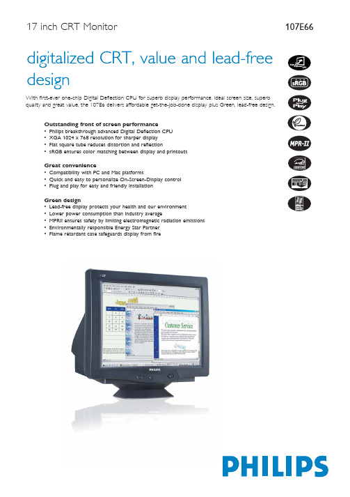
17 inch CRT MonitorCommercial Specifications Digital Deflection CPUAn exclusive Philips innovation -- the world's first one-chip CRT solution -- combines the deflection and the Microcontroller in a single chip to process and control input sync digitally. This innovative technology prevents electronic noise that can harm display quality, reduces display jitter and improves geometry for better front of screen performance.XGA, 1024 x 768 resolutionFor graphics monitors, the screen resolution signifies the number of dots (pixels) on the entire screen. For example, a 1024-by-768pixel screen is capable of displaying 1024 distinct dots on each of 768 lines, or about 786 thousand pixels. XGA provides resolutions of 640 by 480 or 1024 by 768 pixels.Flat square tubeA tube designed to reduce distortion and reflection.sRGB readyCalibrated RGB that is optimized for the vast majority of computer peripherals, monitors, operating systems and browsers, allowing accurate color mapping with very little data overhead.Two platform compatibilityThe ability to work with a variety of platforms; Philips monitors are compatible to connect with PC by employing a VGA connection and connect with Macintosh.OSD (On-Screen-Display control)An on-screen panel for adjusting a monitor. The OSD is used forcontrast, brightness, horizontal and vertical positioning and other monitor adjustments.Easy plug and playThe ability of display device to plug in a PC and operate without requiring user intervention to adjust complicated settings.Lead freeLead-free display products are designed and produced in compliance with strict European Community Restriction of Hazardous Substances (RoHS) standards that restrict lead and other toxic substances that can harm health and the environment.Energy efficiencyReduction of the electrical power required to operate a device to achieve real savings.MPRIIThe world standard setting stringent levels for electromagnetic radiation emitted by monitors.Energy Star PartnerPower conservation requirements set forth by the Environmental Protection Agency of the U.S. government.Flame retardant caseA system of limiting accidental fires by engineering flame retardants into the monitor's case.Product HighlightsTrademarks owned by Royal Philips Electronics2004 © Royal Philips Electronics - All rights reserved As an Energy Star partner, Philips has determined that this product meets the Energy Star guidelines for energy efficiency.Microsoft and Windows are registered trademarks of Microsoft Corporation.All data subject to change without notice Release date: December 2004, Picture/Display• Display Screen Type Flat Square Tube• Panel Size17"/ 41 cm • Phosphor P22• Recommended Display Area 306 x 230 mm (12.0" x 9.0")• Dot Pitch 0.27 mm• Horizontal Dot Pitch0.23 mm • White Chromaticity, 6500º K x = 0.313 / y = 0.329• White Chromaticity, 9300º K x = 0.283 / y = 0.297• Maximum Resolution 1280 x 1024 @ 60 Hz• Recommended Resolution1024 x 768 @ 85 Hz • Factory Preset Modes8 modes: 640 x 480 @ 60 Hz, 640 x 480 @ 85 Hz, 720 x 400 @ 70 Hz, 800 x 600 @ 75 Hz, 800 x 600 @ 85 Hz, 1024 x 768 @ 75 Hz 1024 x 768 @ 85 Hz, 1280 x 1024 @ 60 Hz • Factory Preload Modes 14 modes• Video Dot Rate120 MHz • Horizontal Scanning Frequency 30 - 71 KHz • Vertical Scanning Frequency 50 - 160 Hz • Recommended Refresh Rate 85 Hz• Screen EnhancementsAnti-glare Polarizer, Anti-reflection, Anti-static • Digital Deflection Yes • sRGB Yes • GTF YesConnectivity• Cables D-sub Video Cable, Power Cord • Sync Input Impedance (ohm) 4.7 k • Video Input Impedance (ohm) 75• Video Input Signal Levels 0.7 Vpp • Video Sync Input Signal Separate Sync • Video Sync Polarities Positive and Negative • Cable Connection AC Power inConvenience• Convenience Enhancements Menu Languages,On-screen Display• Monitor Controls Brightness Direct Access, Contrast Direct Access,Menu, Power On/Off • OSD Languages English, French, German, Italian, Spanish, Portuguese, Korean (Simplified Chinese, Russian, Turkish for someRegions)• Plug & Play Compatibility DDC 2BWindows 98/ME/2000/XP • Regulatory Approvals CE Mark, FCC-B, UL, CSA, NUTEK, Energy Star,SEMKO, TÜV/GS, TÜV Ergo, FDA, EZU, GOST, MEEI, PCBC, BSMI, MPRII,Low Emission, E2000• Swivel +/- 90°• Tilt-5° to 13°Accessories• Included Accessories AC Power Cord • Optional Accessories Multimedia Base • User Manual YesDimensions• Depth (with base) 419 mm • Height (with base) 383 mm • Width (with base)397 mm • Temperature Range (Operation) 0°C to 40°C • Temperature Range (Storage) -25°C to 65°C • Weight13.4 kgPower• Complies With Energy Star, NUTEK, E2000• Consumption 64 W (Typical)• Off Mode1 W• Power LED Indicator Off, Flashing Green;Operation, Green • Power SupplyBuilt-in。
Philips 107T4 17英寸彩色显示器说明书
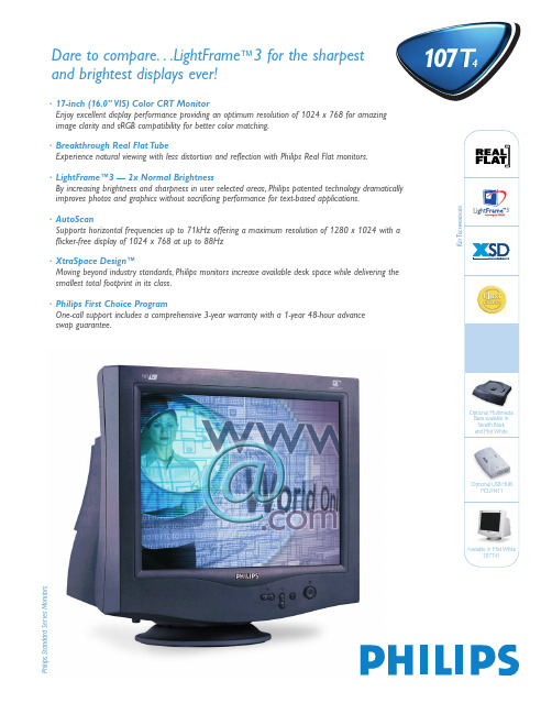
4107T4·17-inch (16.0" VIS) Color CRT MonitorEnjoy excellent display performance providing an optimum resolution of 1024 x 768 for amazing image clarity and sRGB compatibility for better color matching.·Breakthrough Real Flat TubeExperience natural viewing with less distortion and reflection with Philips Real Flat monitors.·LightFrame™3 — 2x Normal BrightnessBy increasing brightness and sharpness in user selected areas,Philips patented technology dramatically improves photos and graphics without sacrificing performance for text-based applications.·AutoScanSupports horizontal frequencies up to 71kHz offering a maximum resolution of 1280 x 1024 with a flicker-free display of 1024 x 768 at up to 88Hz·XtraSpace Design™Moving beyond industry standards,Philips monitors increase available desk space while delivering the smallest total footprint in its class.·Philips First Choice ProgramOne-call support includes a comprehensive 3-year warranty with a 1-year 48-hour advance swap guarantee.Dare to compare...LightFrame ™3 for the sharpest and brightest displays ever!P h i l i p s S t a n d a r d S e r i e s M o n i t o r sOptional USB HUBPCUH411Optional Multimedia Base available in Stealth BlackProduct Number107T43 Stealth Black107T41 Mist WhiteCRT•Size (inch/cm)17"/41 cm (16.0" VIS)•Deflection Angle (degrees)90°•Dot Pitch0.25 mm•Horizontal Pitch0.21 mm-Tube Type REAL FLAT,Flat Shadow Mask,High Contrast,Anti-Static,Anti-Reflection,Light Transmission 45%•Phosphor P22•Recom.Display Area (mm)306 x 230 mm•Recom.Display Area (inch)12.0" x 9.0"•Max.Display Area (mm)325 x 244 mm•Max.Display Area (inch)12.8" x 9.6"Scanning•Horizontal Scanning30 - 71kHz•Vertical Scanning50 - 160HzVideo•Video Dot Rate108MHz•Input Impedance-Video75Ω-Sync 2.2kΩ•Input Signal Levels0.7 Vp-p•Sync Input Signal Separate SyncComposite Sync•Sync Polarities Positive and NegativeWhite Color TemperatureChromaticity CIE Coordinates:•at 9300 K:x=0.283,y=0.297•at 6500 K:x=0.313,y=0.329Resolution and Preset Modes•Max.Resolution1280 x 1024•Recom.Resolution1024 x 768•16 User Definable Modes•22 Factory Preset Modes:Plug and Play Compatibility•Display Data Channel DDC 2B (VESA)•Microsoft®,Windows® 95/98/Me 2000/NT/XP PC2001 compatible•sRGBPower ManagementComplies with EPA Energy Star,NUTEK Specifications•Operation (typ.)68 W•Suspend/Stand-By Mode (typ.)< 2 W•Off Mode/Deep Sleep< 2 WLow-Emission Characteristics•Complies with MPR-II Specifications Monitor Controls and Functions•Main5-Button OSDBrightness +/- Direct AccessContrast+/- Direct Access•On Screen Display Language (English,Spanish,French,German,Italian,Chinese,Portuguese,Korean),Zoom,Horiz/VertPosition and Size,Pincushion,Balanced,Trapezoid,Parallelogram,Color,Reset,Degauss,Moire,SerialNumber,Resolution,Frequency,sRGB •LightFrame™3For improving the picture display of multimediacontent such as photos,videos and games.Willboost brightness and sharpness performance onuser selected areas/ windows on the screen.Withautomatic detection of graphical content in InternetExplorer for the web browsing.Can process up to16 images simultaneously.One-button full screenmode.Advanced user adjustments via Windowscontrol panel.Easy to use control software forWindows 98,Me,XP and 2000.Software in English,French,German,Spanish,Italian,Portuguese,Dutch,Chinese and Korean.Connections and Cables•Connections-Video15-pin D-Sub Input•Cables D-Sub Video (fixed) and Power CordRegulatory Approvals•MPR-II Low Emission•TüV/GS,TüV-Ergo,TüV/9241-3•FCC-B,UL,CSA,DHHS•SEMKO,Poland-B Sign,C-Tick•CE,BCIQ,PSB•NUTEK,Energy StarPhysical Specifications•UPC Code107T43 (Stealth Black)************107T41 (Mist White)************•Unit Dimensions (WxHxD) 15.7" x 16.1" x 16.5"399 x 410 x 419 mm (incl base)15.7" x 14.7" x 16.5"399 x 373 x 419 mm (excl base)•Unit Weight36.4 lbs./16.5 kg•Carton Dimensions (WxHxD) 21.90" x 20.50" x 19.50"556 x 520 x 495 mm•Carton Weight44 lbs./19.96 kg•Power Supply 90 - 264 VAC,50/60Hz•Temperature (operating)0°C to +40°C/32°to 104°F•Temperature (storage)-25°C to +65°C/-13°to 149°F•Relative Humidity5% to 95%•MTBF (excl.CRT)> 75,000 HOptional Accessories•USB Hub Option Type PCUH411•Multimedia Base Option Type 6G3B12 (Stealth Black)6G3B11 (Mist White)•Mac Adapter Free Upon Request via Tech SupportCarton contains:107T Monitor,power cord,and user’s manual on CD. INTERNET ADDRESS:TECHNICAL SUPPORT:(877) 835-1838 (USA)(402) 536-4171 (outside USA)Specifications subject to change without notice.Printed in the U.S.A.,©2003 Philips Consumer Electronics Co.A Division of Philips Electronics North America Corp.As an Energy Star partner,Philips has determined that this product meets the Energy Star guidelines for energy efficiency.Microsoft and Windows are registered trademarks of Microsoft Corporation MacOS is a regis-tered trademark of Apple Computer,Inc.All trademarks acknowledged.Copyright 2001 Koninklijke Philips Electronics N.V.CCM-110-01/03Literature Order Number:107T41/107T43Resolution H.freq V.freq 640 x 35031.5(kHz)70(Hz) 640 x 35037.9(kHz)85(Hz) 640 x 48031.5(kHz)60(Hz) 640 x 48037.9(kHz)72(Hz) 640 x 48037.5(kHz)75(Hz) 640 x 48043.3(kHz)85(Hz) 640 x 48050.6(kHz)100(Hz) 720 x 40031.5(kHz)70(Hz) 720 x 40037.9(kHz)85(Hz) 800 x 60037.9(kHz)60(Hz) 800 x 60048.1(kHz)72(Hz)Resolution H.freq V.freq800 x 60046.9(kHz)75(Hz)800 x 60053.7(kHz)85(Hz)800 x 60063.9(kHz)100(Hz)832 x 62449.7(kHz)75(Hz)1024 x 76848.4(kHz)60(Hz)1024 x 76856.5(kHz)70(Hz)1024 x 76860.0(kHz)75(Hz)1024 x 76868.7(kHz)85(Hz)1152 x 86467.5(kHz)75(Hz)1280 x 96060.0(kHz)60(Hz)1280 x 102464.0(kHz)60(Hz)107 T4T echnical Specifications。
液晶显示器维修手册
液晶显示器维修手册第一章: 引言液晶显示器维修手册是为了帮助用户了解液晶显示器的维修和故障排除方法而编写的。
本手册将提供液晶显示器常见问题的解决方案和处理方法,以确保用户能够迅速恢复屏幕的正常运行。
第二章: 基础知识在进行液晶显示器维修之前,用户需要了解一些基础知识。
液晶显示器是通过液晶技术显示图像的设备。
它是由像素组成的,每个像素都由液晶层和光源背光组成。
用户需要熟悉液晶显示器的组成部分、原理和常见故障类型。
2.1 液晶显示器的组成部分液晶显示器由多个组件组成,包括面板、背光源、控制电路、接口等。
用户需要了解这些组件的功能和相互关系。
2.2 液晶显示器的工作原理液晶显示器的工作原理包括电压控制液晶颗粒来控制光的通过、背光源的照明方式以及图像传输的过程。
用户需要熟悉这些原理,以便更好地进行维修工作。
2.3 常见故障类型液晶显示器常见故障类型包括无法开机、黑屏、色彩失真、图像闪烁等。
用户需要了解每种故障类型的原因和相应的维修方法。
第三章: 维修步骤本章将详细介绍用户在维修液晶显示器时需要采取的步骤。
3.1 故障诊断在开始维修前,用户需要先进行故障诊断。
通过观察、测试和排除法等方法,找出故障产生的原因。
3.2 维修工具和材料准备用户需要准备一些常用的维修工具和材料,如螺丝刀、电压表、焊接工具等。
这些工具和材料在维修过程中起到关键作用。
3.3 维修操作步骤在进行维修操作时,用户需要按照以下步骤进行:1) 关闭电源并拔掉电源线;2) 拆卸外壳以获得维修接触面;3) 检查电源问题,如电源线是否损坏或电源板是否故障;4) 检查信号线或接口问题,确保连接良好;5) 检查背光源是否正常运行;6) 检查控制电路和面板问题;7) 清洁显示屏和其他组件;8) 重新组装并测试修复效果。
第四章: 常见故障与解决方案本章将列举液晶显示器常见的故障情况,并提供相应的解决方案。
4.1 无法开机当液晶显示器无法开机时,可能是由于电源故障、信号线松动或电源线接触不良等原因造成。
显示器关机消亮点电路原理与维修(2)

显示器关机消亮点电路原理与维修(2)显示器关机消亮点电路原理与维修彩显进入节能状态后,微处理器检测到行场同步信号消失以后,在切断12V和6.3V灯丝供电后,还通过FC总线来控制TDA4856的16、17脚输出一定时间的高电平,使得上述电路动作,阴极负压最大来抑制亮点的出现。
在切换分辨率时,为了防止行振荡频率不能及时被主机的`行同步信号锁定而出现不正常的画面,16、17脚同时输出高电平,使G1负压最大,实现黑屏的目的。
当行振荡频率一直不能被行同步信号锁定时,显示器进入行频失锁保护状态,行场振荡电路停振。
为避免在这个瞬间出现亮点,此时16、17脚也会在FC总线的控制下输出高电平,上述相关电路动作,避免了在刚刚进入保护状态时出现亮点。
X射线保护动作时,原理与此相同。
在行频失锁和X射线保护状态下,16、17脚会一直保持高电平,这是与上述其他状态所不同的。
2.飞利浦CM231 7型显示器的关机消亮点电路有关原理见图4。
该机的关机亮点消除电路与ACER’78G型的原理基本相同,这里只介绍不同的部分。
在正常工作状态,CRT的Gl极电压是由行输出变压器5612的9脚输出的电动势经6606、2609整流滤波后形成的一l。
78V电压的基础上,再经:3504、3503、7503进行分压(此时由于7503的e极电压高于b极电压而处于导通状态)后,形成几十伏的负压提供给G1,为CRT的正常工作提供条件。
在关机的瞬间,由于8V电压下降并很快消失,7503迅速截止,G1电压失去了7503的分压,使一178V直接加到G1,从而使电子束截止;同时,12C 总线控制的行场扫描处理集成电路7 5 0 l(T19A4853)的17脚(H?UNLOCK)也会在关机时发出瞬间的高电平,去控制’7502和7504,使之导通。
7502导通后,使得’7503截止,G1负压最大;同时,7504的导通使电容2503的右端电压变为0V,因此也可使G1电压变为最负,电子束截止,消除了关机亮点。
Philips 107S76 数字化真实平面 CRT 显示屏说明书
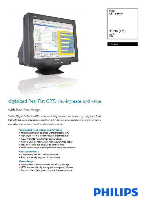
PhilipsCRT monitor43 cm (17")real flatXGA107S76digitalized Real-Flat CRT, viewing ease and valuewith lead-free designWith a Digital Deflection CPU, one-touch brightness enhancement, high brightness RealFlat CRT tube and ideal screen size, the 107S7 delivers an unbeatable mix of performanceand value plus environment-friendly lead-free design.Outstanding front of screen performance•Philips breakthrough advanced Digital Deflection CPU•High Bright Hot Key instantly adjusts brightness levels•XGA 1024x768 resolution for sharper display•Real flat CRT for natural, distortion and glare-free display•Easy-on-the-eyes high-bright, high-contrast tube•sRGB ensures color matching between display and printoutsGreat convenience•Compatibility with PC and Mac platforms•Easy, user friendly plug-and-play installationGreen design•Lower power consumption than the industry average•MPRII ensures safety by limiting electromagnetic radiation•For your safety: Aerospace composite fire retardant caseHighlightsDigital Deflection CPUAn exclusive Philips innovation -- the world's first one-chip CRT solution -- combines the deflection and the Microcontroller in a single chip to process and control input sync digitally. This innovative technology prevents electronic noise that can harm display quality, reduces display jitter and improves geometry for better front of screen performance.High Bright Hot KeyA feature that delivers instant brightness adjustment to the ideal level for viewing text, Internet, game or multimedia applications, providing comfortable viewing and an enhanced experience for each type of application.XGA, 1024 x 768 resolutionFor graphics monitors, the screen resolution signifies the number of dots (pixels) on the entire screen. For example, a 1024-by-768 pixel screen is capable of displaying 1024 distinct dots on each of 768 lines, or about 786 thousand pixels. XGA provides resolutions of640 by 480 or 1024 by 768 pixels.Real flat CRT displayPhilips advanced flat CRT technology reducesglare and reflection more efficiently than aconventional CRT. The special high-bright,high-contrast shadow mask helps maintainsharper focus and eliminates 'color blooming'compared to standard tubes. It displays imageson a monitor that look like images on paper:Viewing the image is more comfortable.Straight lines are straight. Finding a reflection-free viewing position is much easier. This addsup to reduced eyestrain for a comfortableviewing experience.High-bright-high-contrast tubeA CRT tube designed to increase displaybrightness and contrast by increasing the CRTray gun's beam current.sRGB readysRGB is an industry standard that ensures thebest possible match between the colorsdisplayed on your screen and those in yourprintouts.Two-platform compatibilityThe ability to work with a variety of platforms;Philips monitors are compatible to connectwith PC by employing a VGA connection andconnect with Macintosh.Energy efficiencyReduction of the electrical power required tooperate a device to achieve real savings.MPRII compliantThe world standard setting stringent levels forelectromagnetic radiation emitted bymonitors.Flame retardant cabinetPC/ABS plastic composite is the industry's bestand toughest flame-retardant casing material;and is a space-age compound deployed in theaerospace and automotive industries as well asin fire detectors that is compliant with moststringent fire safety standards.Issue date 2021-02-16 Version: 1.0.212 NC: 8639 000 17088 EAN: 87 10895 97266 6© 2021 Koninklijke Philips N.V.All Rights reserved.Specifications are subject to change without notice. Trademarks are the property of Koninklijke Philips N.V. or their respective owners.SpecificationsPicture/Display•Display screen type: Real Flat picture tube •Panel Size: 17"/ 41 cm•Phosphor: P22•Recommended display area(mm): 306 x 230 mm •Recommended Display Area(inch): 12" x 9"•Dot pitch: 0.25 mm•Dot Pitch (horizontal): 0.21 mm•White Chromaticity, 6500K: x = 0.313 / y = 0.329•White Chromaticity, 9300K: x = 0.283 / y = 0.297•Maximum Resolution: 1280 x 1024 @ 60 Hz •Optimum resolution: 1024 x 768 @ 85 Hz •Factory Preset Modes: 8 modes•Factory Preset Mode: 640 x 480 @ 60 Hz, 640 x 480 @ 85Hz, 720 x 400 @ 70 Hz, 800 x 600 @ 75 Hz, 800 x 600 @ 85 Hz, 1024 x 768 @ 75 Hz, 1024 x 768 @ 85 Hz, 1280 x 1024 @ 60 Hz •Factory Preload Modes: 10 modes•Video Dot Rate: 110 MHz•Horizontal Scanning Frequency: 30 - 71 kHz •Vertical Scanning Frequency: 50 - 160 Hz •Recommended Refresh Rate: 85 Hz•Screen enhancement: Anti-glare Polarizer, Anti-Reflection, Anti-Static, High Brightness, High Contrast•Digital deflection•sRGB•GTFConnectivity•Cables: D-sub Video Cable, Power Cord •Cable Connection: AC Power in•Sync input impedance: 2.2k ohm•Video input impedance: 75 ohm•Video input signal levels: 0.7 Vpp•Sync Input: Separate Sync•Video Sync Polarities: Positive and Negative Convenience•User convenience: Menu Languages, On-screen Display •Monitor Controls: Bright Direct Access, Contrast Direct Access, High Bright Hotkey, Menu, Power On/Off•OSD Languages: English, French, German, Italian, Korean, Portuguese, Spanish, Simplified Chinese •Plug & Play Compatibility: DDC 2B, Windows 98/ ME/2000/XP•Regulatory approvals: BSMI, CCC, CE Mark, C-Tick, DHS, eK, FCC-B, UL, CSA, FDA, GOST, IRAM, MIC, MPR-II, Low Emission, NOM, PSB, SEMKO, TÜV/GS, TÜV Ergo•Swivel:+/-90°•Tilt: -5° to 13°Accessories•Included accessories: AC Power Cord•User ManualDimensions•Box dimensions(W x H x D):446 x 420 x 475 mm•Box dimensions in inch (W x H x D):17.6 x 16.5 x 18.7 inch•Set dimensions(W x H x D):397 x 382 x 423.5 mm•Set dimensions in inch (W x H x D):15.6 x 15 x 16.7 inch•Set weight: 13.5 kg•Set weight (lb): 29.7 lb•Weight incl. Packaging: 15.4 kg•Weight incl. Packaging (lb): 33.95•Temperature range (operation): 0°C to 40°C •Temperature range (storage): -25°C to 65°C Power•Consumption(On mode): 62 W (Typical)•Consumption (Off Mode): around 1 W •Power LED indicator: Off - Flashing Green, Operation - green•Power supply: Built-in, 100-264 VAC, 50/60 Hz。
飞利浦 107S9 说明书

安装显示器正视图 •后视图正视图返回页首电源按钮用于开启显示器电源。
MENU “MENU ”按钮按下时会启用OSD 控制器。
(-)对比度热键。
按“(-)” 时 ,“对比度” 的调节控制器会显示或减小调整值。
(+)亮度热键。
按 「(+)」时,会显示「亮度」调节控制器 或增大调整值。
高亮度热键提供 4 种合适的亮度,分别用于文字、Internet 、游戏和多媒体。
1.接入电源-将电缆接入此处的插座。
2.视频输入-该电缆已经与显示器连接。
将电缆另一端与PC连接。
返回页首屏幕显示屏幕显示说明•OSD树 •OSD控制器屏幕显示说明什么是屏幕显示?所有飞利浦显示器均具有该功能。
它允许最终用户直接通过屏幕说明窗口调整显示器屏幕性能。
该用户界面为用户友好型,便于操作。
控制键的基本简单说明在显示器前侧控制器上,您只要按MENU按钮,屏幕显示(OSD)主控制器窗口就会弹出,此时您可以调整显示器的各种功能。
使用(-)或(+)键进行内部调整。
返回返回页首OSD树以下显示了屏幕显示结构全图。
您可以参考该图执行各项调整。
您的显示器不一定包含下面 OSD树中所示的所有项目。
OSD控制器屏幕显示说明• OSD树OSD控制器:亮度(热键)•对比度(热键)•语言•窗口缩放•水平方向位置和大小调整•垂直方向位置和大小调整•形状调整•色温调整•重设为工厂设定值•其他控制器•关闭主控制器亮度欲调整屏幕亮度,请遵循下列步骤。
亮度是屏幕发出的光的总体强度。
建议设定值为50%。
1) 按显示器上的(+) 按钮,出现“亮度”窗口。
2) 按(-) 或(+) 按钮调整亮度。
3) 当亮度调整为需要的水平时,停止按(-) 或(+) 按钮,3秒后亮度窗口消失,新调整值获得保存。
返回页首对比度欲调整屏幕对比度,请执行下列步骤。
对比度是屏幕上浅色区域和深色区域之间的区别。
建议对比度设定为100%。
2) 按(-) 或(+) 按钮调整对比度。
3) 当对比度调整为需要的水平时,停止按(-) 或(+) 按钮,3秒后对比度窗口消失,调整后的设定值获得保存。
飞利浦107S41型彩显电源工作原理分析 第3页
3、高压调整
该机的高压调整(B+电压调整)不是采用电位器调整方式,而是采用微处理器调整方式。当需要降低显像管高压时,7801的B+电压调整端29脚输出的控制信号的占空比增大,通过3858、2820低通滤波获得的直流电压增大。该电压通过3561使7501⑤脚输入的电压增大。7501⑤脚输入的电压增大后,B+电源输出的电压会减小,使显像管高压相应减小,实现高压调整的目的。反之,调整过程相反。
4、行频失锁控制
开机瞬间或显示模式变换瞬间,7501内的行振荡器产生的行频脉冲与同步信号不能及时同步时,750t的17脚输出高电平行频失锁控制电压。该电压通过38t8送到7801的18脚,经3544使7506导通,通过6515、6517、3545使7501的③脚变为低电平。由于③脚是B+电源的误差放大器输出端,所以③脚为低电平后,它的⑥脚不能输出开关管激励脉冲。B+电源电路不能工作;当行振荡器产生的振荡频率与同步信号同步后,17脚变为低电平,不影响7501③脚电位,B+电源开始工作,实现行频失锁/锁定控制。
飞利浦107S41型彩显
本文评论 查看全部评论 (0) 表情: 姓名: 匿名 字数
点评:
同意评论声明 请登录 评论声明
尊重网上道德,遵守中华人民共和国的各项有关法律法规
3联想LXB-HF769A型17英
3脉冲变压器隔离的自激
3用电源厚膜电路
3用电源控制芯片L5991构
Philips 107X4 17英寸色彩显示器用户指南说明书
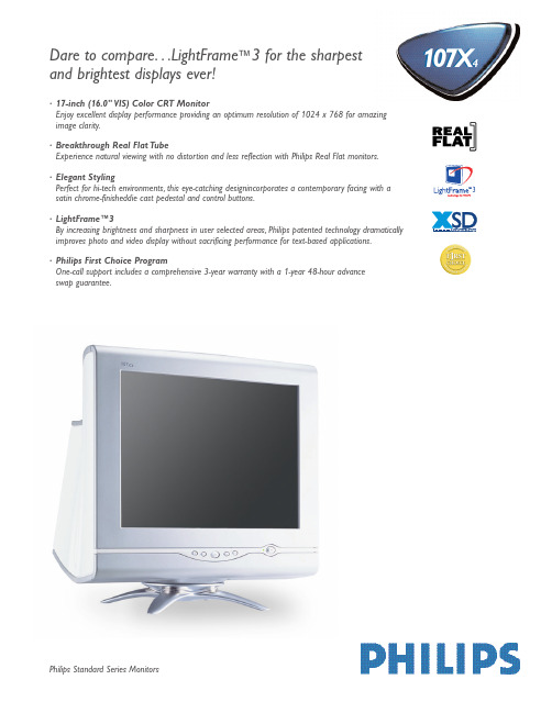
Philips Standard Series Monitors4·17-inch (16.0" VIS) Color CRT MonitorEnjoy excellent display performance providing an optimum resolution of 1024 x 768 for amazing image clarity.·Breakthrough Real Flat TubeExperience natural viewing with no distortion and less reflection with Philips Real Flat monitors.·Elegant StylingPerfect for hi-tech environments,this eye-catching designincorporates a contemporary facing with a satin chrome-finisheddie cast pedestal and control buttons.·LightFrame™3By increasing brightness and sharpness in user selected areas,Philips patented technology dramatically improves photo and video display without sacrificing performance for text-based applications.·Philips First Choice ProgramOne-call support includes a comprehensive 3-year warranty with a 1-year 48-hour advance swap guarantee.Dare to compare...LightFrame ™3 for the sharpestand brightest displays ever!Product Number 107X43CRT•Size (inch/cm)17"/41 cm (16.0" VIS)•Deflection Angle (degrees)90°•Dot Pitch0.25 mm•Horizontal Pitch0.21 mm-Tube Type Shadow Mask,Real Flat,High Contrast,Anti Glare,Anti-Static,Anti-Reflection,Light Transmission 47% •Phosphor P22•Recom.Display Area (mm)306 x 230 mm•Recom.Display Area (inch)12.0" x 9.0"•Max.Display Area (mm)327 x 244 mm•Max.Display Area (inch)12.8" x 9.6"Scanning•Horizontal Scanning30 - 71kHz•Vertical Scanning50 - 160HzVideo•Video Dot Rate108MHz•Input Impedance-Video75Ω-Sync 2.2kΩ•Input Signal Levels0.7 Vp-p•Sync Input Signal Separate SyncComposite Sync•Sync Polarities Positive and NegativeWhite Color TemperatureChromaticity CIE Coordinates:•at 9300 K:x=0.283,y=0.297•at 6500 K:x=0.313,y=0.329Resolution and Preset Modes•Max.Resolution1280 x 1024•Recom.Resolution1024 x 768•16 User Definable Modes•22 Factory Preset Modes:Plug and Play Compatibility•Display Data Channel DDC 2B (VESA)•Microsoft®,Windows® 95/98/Me 2000/NT/XP Compatible•sRGBPower ManagementComplies with EPA Energy Star,NUTEK Specifications•Operation (typ.)68 W•Suspend/Stand-By Mode (typ.)< 2 W•Off Mode/Deep Sleep< 2 WLow-Emission Characteristics•Complies with TCO '95Monitor Controls and Functions•Main5-Button OSD Brightness +/- Direct AccessContrast+/- Direct Access•On Screen Display Language (English,Spanish,French,German,Italian,Chinese,Portuguese,Korean),Zoom,Horiz/VertPosition and Size,Pincushion,Balanced,Trapezoid,Parallelogram,Color,Reset,Degauss,Moire,SerialNumber,Resolution,Frequency,sRGB •LightFrameTM3For improving the picture display of multi mediacontent such as photos,videos and games.Willboost brightness and sharpness performance onuser selected areas/ windows on the screen.Withautomatic detection of graphical content in InternetExplorer for the web browsing.Can process up to16 area simultaneously.One-button full screenmode.Advanced user adjustments via Windowscontrol panel.Easy to use control software forWindows 98,Me.XP and 2000.Software in English,French,German,Spanish,Italian,Portuguese,Dutch,Chinese and Korean (for Windows version) andEnglish,French,German,Spanish (for MacOS).Functionality for the MacOS version differs from theWindows version.Connections and Cables•Connections-Video15-pin D-Sub Input•Cables D-Sub Video (fixed) and Power CordRegulatory Approvals•TÜV/GS,TÜV/Ergo,TÜV/9241-3•FCC-B,UL,CSA,DHHS•SEMKO,Poland-B sign,C-Tick•CE,BCIQ,PSB•NUTEK,Energy StarPhysical Specifications•UPC Code107X43************•Unit Dimensions (WxHxD)16.1" x 17.1" x 17.5"410.2 x 435 x 443.5 mm (incl base)•Unit Weight39.7 lbs./18.0 kg•Carton Dimensions (WxHxD) 22.30" x 21.70" x 20.00"566 x 551 x 508 mm•Carton Weight46 lbs./20.87 kg•Power Supply 90 - 264 VAC,50/60Hz•Temperature (operating)0°C to +40°C/32°to 104°F•Temperature (storage)-25°C to +65°C/-13°to 149°F•Relative Humidity5% to 95%•MTBF (excl.CRT)> 75,000 HCarton contains:107X Monitor,power cord,and user’s manual on CD. INTERNET ADDRESS:TECHNICAL SUPPORT:(877) 835-1838 (USA)(402) 536-4171 (outside USA)CCM-110-9/02Literature Order Number:107X43Resolution H.freq V.freq 640 x 35031.5(kHz)70(Hz) 640 x 35037.9(kHz)85(Hz) 640 x 48031.5(kHz)60(Hz) 640 x 48037.9(kHz)72(Hz) 640 x 48037.5(kHz)75(Hz) 640 x 48043.3(kHz)85(Hz) 640 x 48050.6(kHz)100(Hz) 720 x 40031.5(kHz)70(Hz) 720 x 40037.9(kHz)85(Hz) 800 x 60037.9(kHz)60(Hz) 800 x 60048.1(kHz)72(Hz)Resolution H.freq V.freq800 x 60046.9(kHz)75(Hz)800 x 60053.7(kHz)85(Hz)800 x 60063.9(kHz)100(Hz)832 x 62449.7(kHz)75(Hz)1024 x 76848.4(kHz)60(Hz)1024 x 76856.5(kHz)70(Hz)1024 x 76860.0(kHz)75(Hz)1024 x 76868.7(kHz)85(Hz)1152 x 86467.5(kHz)75(Hz)1280 x 96060.0(kHz)60(Hz)1280 x 102464.0(kHz)60(Hz)4T echnical Specifications。
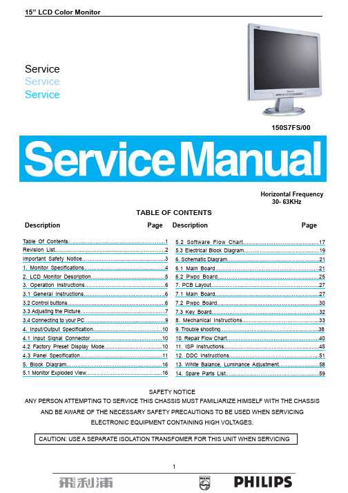
飞利浦150S7FS液晶显示器维修电路图纸(英文版)
Service Service Service150S7FS/00Horizontal Frequency30- 63KHzTABLE OF CONTENTSDescription Page Description PageSAFETY NOTICEANY PERSON ATTEMPTING TO SERVICE THIS CHASSIS MUST FAMILIARIZE HIMSELF WITH THE CHASSISAND BE AWARE OF THE NECESSARY SAFETY PRECAUTIONS TO BE USED WHEN SERVICINGELECTRONIC EQUIPMENT CONTAINING HIGH VOLTAGES.Table Of Contents..............................................................1Revision List.....................................................................2Important Safety Notice...................................................31. Monitor Specifications...................................................42. LCD Monitor Description..............................................53. Operation instructions.................................................63.1 General Instructions..............................................63.2 Control buttons........................................................63.3 Adjusting the Picture.......................................................73.4 Connecting to your PC ..................................................94. Input/Output Specification...........................................104.1 Input Signal Connector..............................................104.2 Factory Preset Display Mode......................................104.3 Panel Specification....................................................115. Block Diagram........................................................165.1 Monitor Exploded View..............................................16 5.2 Software Flow Chart..........................................175.3 Electrical Block Diagram................................................196. Schematic Diagram............................................................216.1 Main Board..........................................................216.2 Pwpc Board........................................................257. PCB Layout....................................................................277.1 Main Board................................................................277.2 Pwpc Board.............................................................307.3 Key Board.............................................................328. Mechanical Instructions..............................................339. Trouble shooting.........................................................3810. Repair Flow Chart.....................................................4011. ISP Instructions............................................................4512. DDC Instructions......................................................5113. White Balance, Luminance Adjustment..........................5814.Spare Parts List (59)Revision ListVersion Release Date Revision History TPV modelT560KGMDBPPHNP A00 Mar.20, 2006 Initial releaseT560KQMDBPPHNPImportant Safety NoticeProper service and repair is important to the safe, reliable operation of all Philips Company** Equipment. The service procedures recommended by Philips and described in this service manual are effective methods of performing service operations. Some of these service operations require the use of tools specially designed for the purpose. The special tools should be used when and as recommended.It is important to note that this manual contains various CAUTIONS and NOTICES which should be carefully read in order to minimize the risk of personal injury to service personnel. The possibility exists that improper service methods may damage the equipment. It is also important to understand that these CAUTIONS and NOTICES ARE NOT EXHAUSTIVE. Philips could not possibly know, evaluate and advise the service trade of all conceivable ways in which service might be done or of the possible hazardous consequences of each way. Consequently, Philips has not undertaken any such broad evaluation. Accordingly, a servicer who uses a service procedure or tool which is not recommended by Philips must first satisfy himself thoroughly that neither his safety nor the safe operation of the equipment will be jeopardized by the service method selected.* * Hereafter throughout this manual, Philips Company will be referred to as Philips.WARNINGUse of substitute replacement parts, which do not have the same, specified safety characteristics may create shock, fire,or other hazards.Under no circumstances should the original design be modified or altered without written permission from Philips. Philipsassumes no liability, express or implied, arising out of any unauthorized modification of design.Servicer assumes all liability.FOR PRODUCTS CONTAINING LASER:DANGER-Invisible laser radiation when open. AVOID DIRECT EXPOSURE TO BEAM.CAUTION-Use of controls or adjustments or performance of procedures other than those specified herein may result in hazardous radiation exposure.CAUTION -The use of optical instruments with this product will increase eye hazard.TO ENSURE THE CONTINUED RELIABILITY OF THIS PRODUCT, USE ONLY ORIGINAL MANUFACTURER'S REPLACEMENT PARTS, WHICH ARE LISTED WITH THEIR PART NUMBERS IN THE PARTS LIST SECTION OF THIS SERVICE MANUAL.Take care during handling the LCD module with backlight unit-Must mount the module using mounting holes arranged in four corners.-Do not press on the panel, edge of the frame strongly or electric shock as this will result in damage to the screen. -Do not scratch or press on the panel with any sharp objects, such as pencil or pen as this may result in damage to thepanel.-Protect the module from the ESD as it may damage the electronic circuit (C-MOS).-Make certain that treatment person’s body is grounded through wristband.-Do not leave the module in high temperature and in areas of high humidity for a long time.-Avoid contact with water as it may a short circuit within the module.-If the surface of panel becomes dirty, please wipe it off with a soft material. (Cleaning with a dirty or rough cloth may damage the panel.)1. Monitor SpecificationsScreen type Active matrix - TFT LCDPanel Type LM150X8-TL03 (LPL) QD15XL13-Rev.01 (QDI)Size 380mm(15.0") Pixel pitch 0.297mm(H) x 0.297mm(V)Viewable angle (CR>10) Horizontal ± 65 Vertical + 45º, - 55º (LPL) Horizontal ± 60Vertical + 45º,- 55º (QDI)LCD PanelResponse time 8ms (type) (LPL) 16ms (type) (QDI)Video R, G, B Analog InterfaceSeparate Sync TTL level, input impedance 2.2k OHM terminateH-Frequency 30kHz – 63kHzInputV-Frequency 56 - 76HzDisplay Colors 16.2 MVideo dot rate 80MHzMaximum Resolution 1024 x 768 at 76Hz (analog input) Recommended Resolution 1024 x 768 at 60Hz (analog input)Plug & Play VESA DDC2BPower Consumption Power on: < 23 W Power off: < 1 WInput Connector D-Sub 15pinAnalog R/G/B separate inputs, H/V sync separated, Composite (H+V) TTL level, SOG syncInput Video Signal 0.7 Vp-p, input impedance, 75 ohm @DC Tilt -5°~ 25°Maximum Screen Size Horizontal: 304.1mm;Vertical: 228.1mm Power Source 90-264 V AC, 50/60 ± 2 HzEnvironmental Considerations Operating Temp: 0° to 35°C Operating Humidity: 80%Max Storage Temp.: -20° to 60°C Storage Humidity: 85%MaxWeight (Net) 2.8 kg Cabinet color Silver2. LCD Monitor DescriptionThe LCD MONITOR will contain a main board, PWPC board, keypad board, which house the flat panel control logic, brightness control logic and DDC.The power board will provide AC to DC Inverter voltage to drive the backlight of panel and the main board chips each voltage.3. Operation instructions3.1 General InstructionsPress the power button to turn the monitor on or off. The other control buttons are located at front panel of the monitor. By changing these settings, the picture can be adjusted to your personal preferences.- The power cord should be connected.- Connect the video cable from the monitor to the video card.- Press the power button to turn on the monitor, the power indicator will light up.3.2 Control ButtonsFront ViewBack View3.3 Adjusting the PictureThis is a feather in all Philips LCD monitors. It allows an end user to adjust screen performance of the monitors directly through an on-screen instruction window. The user interface provides user-friendliness and ease-of-use when operating the monitor.When you press the button on the front control of your monitor, the On-Screen Display (OSD) main controlswindow will pop up and you can then start making adjustments to your monitor’s various features. Use theor the keys to make your adjustments.The OSD treeBelow is an overall view of the structure of the On-Screen Display. You can use this as a reference when you want to work your way around the different adjustments later on.For Europe Model only:3.4 Connecting to the PC1) Connect the power cord to the back of the monitor firmly. (Philips has pre-connected) VGA cable for the first installation.)2) Connect to PC(a) Turn off your computer and unplug its power cable.(b) Connect the monitor signal cable to the video connector on the back of your computer.(c) Plug the power cord of your computer and your monitor into a nearby outlet.(d) Turn on your computer and monitor. If the monitor displays an image, installation is complete.4. Input/Output Specification 4.1 Input Signal Connector4.2 Factory Preset Display Modes4.3 Panel Specification4.3.1 Display Characteristics For LM150X08 PanelFor QD15XL13 Panel4.3.2 Optical CharacteristicsFor LM150X08 PanelTa= 25±2°C, V LCD=3.3V, f V=60Hz, D clk=65MHz, I Lamp=8mAFor QD15XL13 PanelTa=25℃, V CC=+3.3V.4.3.3 Electrical Characteristics For LM150X08 PanelFor QD15XL13 Panel15” LCD Color Monitor165. Block Diagram5.1 Monitor Exploded View1) MCU Initializes.2) Is the EEprom blank?3) Program the EEprom by default values.4) Get the PWM value of brightness from EEprom.5) Is the power key pressed?6) Clear all global flags.7) Are the AUTO and SELECT keys pressed?8) Enter factory mode.9) Save the power key status into EEprom.Turn on the LED and set it to green color. Scalarinitializes.10) In standby mode?11) Update the lifetime of back light.12) Check the analog port, are there any signals coming?13) Does the scalar send out an interrupt request?14) Wake up the scalar.15) Are there any signals coming from analog port?16) Display "No connection Check Signal Cable" message. And go into standby mode after the message disappears.17) Program the scalar to be able to show the coming mode.18) Process the OSD display.19) Read the keyboard. Is the power key pressed?5.3 Electrical Block Diagram 5.3.1 Main Board5.3.2 Inverter/Power Board6. Schematic Diagram6.1 Main BoardPHILIPS 150S-ADC InputC715G1711-1 for 150S7A455Thursday, March 02, 2006Title Size Document NumberRev Date:SheetofCN40412x2 PIN/2.0mmPHILIPS 150S-PANEL OUTPUTC715G1711-1 for 150S7A435Thursday, March 02, 2006Title Size Document NumberRev Date:Sheetof1/8WFB703 120 OHM6.2 Pwpc BoardMODEL:PWPC1521LPR1PHILIPS 15"C1.POWER OUTPUT 12V & 3.3 VAOC (Top Victory) Electronics Co., Ltd.B 12Monday, October 17, 2005Title Size Document NumberRevDate:Sheetof7. PCB Layout 7.1 Main Board7.2 Pwpc Board7.3 Key Board8. Mechanical Instructions1. Back View as Fig.1Fig.12. Remove base as Fig.2- Fig.3a. Remove 1 screw for hinge cover as Fig.2b. Remove 5 screws for base as Fig.3Fig.2Fig.33. Remove rear cover as Fig.4- Fig.6a. Remove 2 screws for back cover as Fig.4b. Using the “1” type screwdriver to open the 3 clicks on bottom side as Fig.5Fig.4Fig.5Fig.64. Remove shield as Fig.7Remove 6 screws as Fig.7Fig.7 5. Remove main and pwpc board as Fig.8Remove 13 screws for main and pwpc board as Fig.8Fig.86. Remove the bezel as Fig.9- Fig.11a. Remove 2 screws at the right of bezel as Fig.9b. Remove 2 screws at the left of bezel as Fig.10c. Remove connect wire between main and key board as Fig.11Fig.9Fig.10Fig.117. Remove the main frame as Fig.12- Fig.14a. Remove 2 screws at the right of main frame Fig.12b. Remove 2 screws at the left of main frame Fig.13Fig.12Fig.13Fig.149. Trouble ShootingThis page deals with problems that can be corrected by a user. If the problem still persists after you have tried these solutions, contact Philips customer service representative.10. Repair Flow Chart (1). No Power(4). Keypad Board9.2.2 Power/Inverter Board No powerAdapter BoardInverter Board No power11. ISP Instruction (Take 170S model for example)(1). Install the program softwarea. First decompressing files, as follow:b. Double – click , start to install as follows:c. There will be a shortcut key appears on the desktop.(2). Connect the ISP board as follow:a. Double-click ,running the program as follows:Connect to the PC LPTb. Click icon, search the program”PHILIPS_170S_QDI_QD17EL0711_AP_036.HEX”, and click open:Note: When it is 150s model, you can select (for LPL panel) or (for QDI panel)c. After click “OPEN”, there would be a dialog box, select .c. Click icon, the writer is in processing…d. Until appears the follow Fig, writer completed.。
飞利浦中文维修手册-内销
飞利浦超级单片彩电原理与维修一、UOC-TOP 机芯简介1.主芯片特点:采用菲利浦最新超级单片TDA111XXPS,TDA121XXPS系列,极高集成度,最大限度减少外围元件数量.双列直插式64脚封装,方便生产.所有型号芯片PIN to PIN,同一块机芯可更换不同型号芯片,实现不同的功能,适用于全球电视市场内置多项最新图象改善技术,全面提升画质.2.功能特点:新颖OSD风格,拉幕式菜单,支持中文、英文、越南文、泰文、印尼文、阿拉伯文.增加彩色矩阵选择,用户可根据个人喜好选定彩色风格.增加地磁校正功能,消除地磁影响.增加彩色增强功能,包括清晰度提升,黑电平延伸,白峰限制,数字降噪等画质改善技术,相比前代机芯,具有画面清晰度高,层次丰富,图象轮廓清晰的优点.色温选择功能,用户可选择标准色温,暖色调或冷色调.兼容FS和VS高频头具有开关机拉幕功能,上下模式和左右模式可选可选AKB功能,当将AKB设置为关的时候,电路成本可以降低200频道记忆可选双喜字LOGO,用户也可以自编LOGO,开机和无信号时都能显示LOGO万年历和游戏功能定时开关机功能.节目交换功能.3.机芯调试特点:简单方便的调试方法,符合工厂调试习惯.内置7种测试信号(十字格,方格,暗场,白场,红场,蓝场,绿场等),可用于调整几何及白平衡,可不需要专门的测试信号发生器.增加阴极电平调整(CL),以适应不同显像管包括旧管的电子枪特性,达到最佳图象效果.增加暗电平偏移功能(BLOC),各种不同型号的显像管包括旧管均可调整到最佳的RGB截止及驱动电平.多项设置确保加速极电压调整方便,一致性好.增加了左右行消隐的调整,方便配置不同参数的显象管SANYO码遥控器和NEC码遥控器可选.4.硬件组成部分飞利浦超级单片机芯以TDA111XXPS、TDA121XXPS(N201)系列为核心,并配备存储器ATM24C08(N701)、伴音功放电路TDA2003(N601)、场输出电路LA78041(N451)、A3开关电源电路(V513)、高频调谐器CWC-5053-V8(A101)、行扫描电路和视频放大电路等组成。
- 1、下载文档前请自行甄别文档内容的完整性,平台不提供额外的编辑、内容补充、找答案等附加服务。
- 2、"仅部分预览"的文档,不可在线预览部分如存在完整性等问题,可反馈申请退款(可完整预览的文档不适用该条件!)。
- 3、如文档侵犯您的权益,请联系客服反馈,我们会尽快为您处理(人工客服工作时间:9:00-18:30)。
1Service Service Service107S70Horizontal Frequency30-71 kHzTable of contentsDescription Page Description PageSAFETY NOTICEANY PERSON ATTEMPTING TO SERVICE THIS CHASSIS MUST FAMILIARIZE HIMSELF WITH THE CHASSIS AND BE AWARE OF THENECESSARY SAFETY PRECAUTIONS TO BE USED WHEN SERVICING ELECTRONIC EQUIPMENT CONTAINING HIGH VOLTAGES.Jan.25 2006GB:Table Of Contents...................................................1Revision List.......................................................2Important Safety Notice.................................31. Specifica tions..........................................42. Precaution and notices................................72-1Safety precautions.......................................72-2 Product safety notice ..........................................72-3 Service Notices......................................72-4 High voltage warning.............................................83. Operating Instructions.............................................94. Adjustment .......................................................104 -1. Adjustment conditions and precautions .................104-2. Main adjustments..................................................104-3 Adjustment methods........................................104-4 EDID content.....................................................135.Circuit description .........................................145-1.Micro controller and deflection circuit ..........145-2.Transistor & diode circuit. (16)6. Trouble shooting chart......................................176-1.Noraster,CRT relative circuit problems...................176-2. Abnormal displays...................................................196-3 No blanking................................................206-4 Hor./OSC/DEF/HV circuit fault................................206-5. Abnormal horizontal deflection...................................216-6. Abnormal vertical scanning.......................................226-7. S i d e -p i n c u s h i o n d i s t o r t i o n..................226-8. Poor focus................................................226-9. Power supply trouble shooting chart.................237. Mechanical of cabinet front dis-assembly..........248. Spare parts list..........................................259 Block diagram............................................4010 IC block diagrams.............................................4111 P C B la yout............................................4511-1 Main PCB layout..........................................4511-2. CRPC board layout.........................................4612. Schematic diagram.. (47)Revision ListVersion Date Revision History TPV Model Name A00 Jan-25-2006 Initial Release B774BAPWPHN1P2Important Safety NoticeANY PERSON ATTEMPTING TO SERVICE THIS CHASSIS MUST FAMILIARIZE HIMSELF WITH THE CHASSIS AND BE AWARE OF THE NECESSARY SAFETY PRECAUTIONS TO BE USED WHEN SERVICING ELECTRONIC EQUIPMENT CONTAINING HIGH VOLTAGES.CAUTION: USE A SEPARATE ISOLATION TRANSFORMER FOR THIS UNIT WHEN SERVICINGREFER TO BACK COVER FOR IMPORTANT SAFETY GUIDELINGSProper service and repair is important to the safe, reliable operation of all Dell Company** Equipment. The service procedures recommended by Dell and described in this service manual are effective methods of performing service operations. Some of these service operations require the use of tools specially designed for the purpose. The special tools should be used when and as recommended.It is important to note that this manual contains various CAUTIONS and NOTICES which should be carefully read in order to minimize the risk of personal injury to service personnel. The possibility exists that improper service methods may damage the equipment. It is also important to understand that these CAUTIONS and NOTICES ARE NOT EXHAUSTIVE. Dell could not possibly know, evaluate and advise the service trade of all conceivable ways in which service might be done or of the possible hazardous consequences of each way. Consequently, Dell has not undertaken any such broad evaluation. Accordingly, a servicer who uses a service procedure or tool which is not recommended by Dell must first satisfy himself thoroughly that neither his safety nor the safe operation of the equipment will be jeopardized by the service method selected.* * Hereafter throughout this manual, Dell Company will be referred to as Dell.WARNINGUse of substitute replacement parts, which do not have the same, specified safety characteristics may create shock, fire, or other hazards.Under no circumstances should the original design be modified or altered without written permission from Dell. Dell assumes no liability, express or implied, arising out of any unauthorized modification of design. Servicer assumes all liability.341. Monitor Specifications1. CRT : 43.2CM(17") F&S high contrast CRT, 90 Deflection, 29mm Neck, 0.25mm phosphor dot pitch, Non-Glare Screen ,anti-static2. Viewable image Size: 40.6CM (16") diagonal3.Display Color: Unlimited Colors4. External Controls:Power On/Off, OSD key, OSD Function: Contrast, Brightness, H-Center, H-Size, H-Center, V-Size, Zoom, Pincushion, Trapezoid, Pin-Balance, Parallelogram, Rotation, 6500 Color Temperature, User Color, 9300 Color Temperature, Degauss, Moire Reduce, Recall, Exit, Language.5. Input Video Signal6. Display SizeHorizontal: 306mm ± 4mm Vertical: 230mm ± 4mm7. Scanning FrequenciesHorizontal: 30KHz ~ 71KHz Vertical: 50 Hz ~ 160 Hz8. Factory Preset Timings: 8User Timings: 6 GTF supported9. MisconvergenceZone A < 0.25 mm Zone B< 0.35 mm< 0.4mm (for modes < 50kHz).10. Video Bandwidth: 110 MHz11. Power Source:Switching Mode Power SupplyAC 90 ~264V, 50/60 ± 3 Hz Universal Type.Timing 1. 2. 3. Resolution 640 x 480 640 x 480 720 x 400 H. Frequency 31.469 kHz 43.269 kHz 31.468 kHz V. Frequency 59.941 Hz 85.008 Hz 70.084 HzH/V sync polarity- / - - / - - / + Timing 4. 5. 6. Resolution 800 x 600 800 x 600 1024 x 768 H. Frequency 46.875 kHz 53.674 kHz 60.023 kHz V. Frequency 75.000 Hz 85.061 Hz 75.029 HzH/V sync polarity+ / + + / + + / + Timing 7. 8.Resolution 1024 x 768 1280 x 1024 H. Frequency 68.677 kHz 63.981 kHz V. Frequency 84.997 Hz 60.020 HzH/V sync polarity+ / + + / +512. Operating Temperature: 0°C to 40°C Ambient13. Humidity: 5% to 90% Relative, Non-Condensing14. Weight: Net weight - 13.5 kgGross weight - 15.8 kg (for China, India)15.4 kg (for other regions)15. Dimensions Monitor:Unit dimension (with stand) - 397mm (W) x 382mm (H) x 423.5mm (D)Packed unit dimension (carton) - 460mm (W) x 450mm (H) x 526mm (D) for China, India446mm (W) x 420mm (H) x 475mm (D) for other regions 16. External Connection:15 Pin D-type Connector AC Power Cord17. Power Consumption Modes :Power on - < 75w.DPMS off state - < 2w at 240Vac.Power off (by switch) - < 1w at 120Vac, <2w at 240Vac.18.Regulations:International Regulatory SpecificationCountryDomain Safety / EMC / Ergonomics / StandardsDocumentsINTERNATIONAL Sa IEC60950-1: 2001. Group -and nationaldifferences of all countries listed in CBBulletin No. 107ACB Report and CB certificateSa European Low Voltage Directives 73/23/EEC and 93/68/EECDeclaration of ConformityEuropean Electromagnetic Compatibility Directive 89/336/EEC amended by the directive 93/68/EEC. EN 55022:1998 Class BEN 55024: 1998 EN 61000-3-2: 2000IEC 61000-3-3: 1994/EN61000-3-3: 1995EUROPEECISPR 22:1997 Class B International EMC standardDeclaration of Conformity and Full EMC/CEtest reportSa EN60950-1: 2001TUV certificate OISO 9241-3-7-8 (CRT) & 13406-2 (LCD),prEN 50279:1998 TUV-ERG certificate O GS-Mark / EK1-ITB 2000 TUV-GS certificateGERMANYXDecree ROV 08.01.87 (CRT)PTB6Sa EN60950-1: 2001SEMKO certificateO TCO 99 (TCO03) (to TCO models) TCO99 (TCO03) report + certificateSWEDENOMPR 1990: 8 / MPR 1990:10 (to MPRmodels)Meet requirement RUSSIA Sa GOST R 50377-1992GOST certificate Sa SABS IEC 60950 and IEC 60950-1 Certificate of Conformity SOUTH AFRICAE EN55022 or Cisper 22 Certificate of ConformitySaUL 60950-1: 2003 UL certificate E FCC Part 15 Class B FCC ID grant or DOC O Energy StarEPA registration USAX 21CFR 1002.10 to 13 (CRT) DHHS report SaCSA C22.2 No 60950 CSA certificate EICES-003 issue 3Statement on labelCANADAE RED (CRT)DNHW MEXICO Sa NOM-019-SCFI-1994NOM certificate SaKorean Safety Control law IEC 60950 eK certificate KOREAERegulations laws: EMI 1996-78, 80. EMS1996-79,81MIC certificate SINGAPORE Sa IEC60950PSB certificate Sa GB4943-2001E GB9254-1998; 17625.1-2003 CCC certificate CHINAO CSC/G1205-2004 CECP certificate SaCNS-14336 (IEC 60950-1) E CNS-13438 (CISPR22) Class B BSMI certificate TAIWAN O Criteria 18 (Monitor) (LCD) Green Mark / certificate AUSTRALIA/ NEW-ZEALANDE AS/NZS3548: 1995Declaration of Conformity S IS 1121, IEC60950/IEC60950-1 Certificate of Conformity ISRAELEEN or Cisper 22Certificate of ConformityS IEC standard SASO Saudi ArabiaE IEC standard SASO Sa EN60950-1:001 (AC adapter only) PSE JapanEVCCI class B (CISPR 22)VCCI CertificateArgentina Sa EN60950-1: 2001IRAMSa = SafetyE = Electromagnetic CompatibilityO = Other which including recycling, energy saving, ergonomics X = X-rayFor detailed regulatory items please refer to the international regulatory specification provided by Philips.2. Precautions and notices2-1.Safety precautions1. Observe all caution and safety related notes located inside the display cabinet.2. Operation of the display with the cover removed, may cause a serious shock hazard from the display powersupply. Work on the display should not be attempted by anyone who is not thoroughly familiar with precautions necessary when working on high voltage equipment.3. Do not install, remove or handle the picture tube in any manner unless shatter-proof goggles are worn.People who are not so equipped should be kept away while handling picture tube. Keep picture tube away from the body while handling.4. The picture tube is constructed to limit X-RAY radiation to 0.5 mR/HR. For continued protection, use thedesignated replacement tube only, and adjust the voltages so that the designated maximum rating at the6. Symbol”means X-ray relative parts. Before replacing any of these components please read the partslist in this manual carefully to avoid creating higher anode voltage or x-ray. Especially for sealed controls, such as VR902, VR903, VR701 and FBT screen VR etc, which were sealed by the manufacturer once their optimum position has been set, please don’t dismantle them as your likes, otherwise you will break or damage the component. If you need replace the parts with sealed control, please adjust the relative VR to make sure the B+ voltage under 59V and well seal it with A+B glue or equivalent, which you can not move away with one screw driver7. Before returning a serviced display to the customer, a thorough safety test must be performed to verify thatthe display is safe to operate without danger or shock. Always perform an AC leakage current check on the exposed metallic parts of the cabinet, such as screw heads.Test method for current leakage is described as follow.(a) Plug the AC line cord directly into rated AC outlet (do not use a line isolation transformer during thischeck).(b) Use an AC voltmeter having 5000 ohms per volt or with more sensitivity in the following manner:Connect a 1500 ohms 10 Watt resistor, paralleled by a 0.15UF, AC type capacitor between a knowngood earth ground (water pipe, conduit, etc.) and the exposed metallic parts simultaneously. Measurethe AC voltage across the combination of 1500 ohms resistor and 0.15UF capacitor.(c) Reverse the AC plug at the AC outlet and repeat AC voltage measurements for each exposed metallicpart.(d) Voltage measured must not exceed 0.5 volts RMS. This corresponds to 0.35 milliamp AC. Any valueexceeding this limit constitutes a potential shock hazard and must be corrected immediately.2-2 Product safety noticeMany electrical and mechanical parts in this chassis have special safety visual inspections and the protection afforded by them cannot necessarily be obtained by using replacement components rated for higher voltage, wattage, etc. Before replacing any of these components read the parts list in this manual carefully. The use of substitute replacement parts which do not have the same safety characteristics as specified in the parts list may create shock, fire, X-RAY radiation or other hazards.2-3 Service notes1. When replacing parts or circuit boards, clamp the lead wires around terminals before soldering.2. When replacing a high wattage resistor (more than 1/2W of metal oxide film resistor) in circuit board, keepthe resistor about 10mm (1/2 in) away from circuit board.3. Keep wires away from high voltage or high temperature components.4. Keep wires in their original position so as to reduce interference.72-4 High voltage warningOperation of monitor outside of cabinet or with back removed may cause a serious shock hazard. Work on this model should only be performed by those who are thoroughly familiar with precautions necessary when working on high voltage equipment.Exercise care when servicing this chassis with power applied. Many B plus and high voltage terminals are exposed which, if carelessly contacted, can cause serious shock or result in damage to the chassis. Maintain interconnecting ground lead connections between chassis and picture tube dag when operating chassis.Certain HV failures can increase X-ray radiation. Monitor should not be operated with HV levels exceeding the specified rating for the chassis type. The maximum operating HV specified for the chassis used in this monitor is 25KV ±0.8KVwith a line voltage of 120/240 VAC. Higher voltage may also increase possibility of failure in HV supply.It is important to maintain specified values of all components in the horizontal and high voltage circuits and anywhere else in the monitor that could cause a rise in high voltage or operating supply voltages. No changes should be made to the original design of the monitor. Components shown in the shaded areas on the schematic should be replaced with exact factory replacement parts. The use of unauthorized substitute parts may create a shock, fire or other hazard.To determine the presence of high voltage, use accurate, high impedance, HV meter connected between second anode lead and CRT dag grounding device. When servicing the High Voltage System, remove static charge from it by connecting a 10K ohm resistor in series with an insulated wire (such as a test probe) between picture tube dag and 2nd anode lead.(AC line cord disconnected from AC power outlet.)The picture tube used in this monitor employs integral implosion protection. Replace with tube of the same type number for continue safety. Do not lift picture tube by the neck. Handle the picture tube only after discharging the high voltage completely.893. Operating instructionsThis procedure gives you instructions for installing and using the Color display.1. Position the display on the desired operation and plug the power cord into a convenient AC outlet. Three-wire power cord must be shielded and is provided as a safety precaution as it connects the chassis and cabinet to the electrical conduit ground. If the AC outlet in your location does not have provisions for the grounded type plug, the installer should attach the proper adapter to ensure a safe ground potential.2. Connect the 15-pin color display shielded signal cable to your signal system device and lock both screws onthe connector to ensure firm grounding. The connector information is as follow:15 - Pin Color Display Signal CablePin No. Description Pin No. Description 1. Red video 9. +5V (Supply from PC for DDC circuit) 2.Green video10. Sync GND 3. Blue video 11. GND4. Self test 12. DDC serial data5. DDC return 13.H-sync 6. Red GND 14. V-sync 7.Green GND15. DDC serial clock 8. Blue GND3. Apply power to the display by turning the power switch to the "ON" position and allow about thirty secondsfor display tube warm-up. The Power-On indicator lights when the display is on.4. With proper signals feed to the display, a pattern or data should appear on the screen, adjust the brightnessand contrast to the most pleasing display.5. This monitor has power saving function following the VESA DPMS. Be sure to connect the signal cable tothe PC.6. If your color display requires service, it must be returned with the power cord.104. Adjustment4-1. Adjustment conditions and precautions1. Approximately 30 minutes should be allowed for warm up before proceeding.2.Adjustments should be undertaken only on those necessary elements since most of them have been carefully preset at the factory.4-2 Main adjustments- High Brightness PCB - MAIN HB 4 levels hot key selection4-3 Adjustment method1. TP901, B + & HV voltage adjustment:A. Chroma-2135 Signal generator or PC equivalent set mode 6, UVGA 640X480 pattern 101 .B. Connect a DC Volt meter between TP902 and ground, then adjust VR902 to be 57±0.2 VDC for CPT andLPDCRT.C. Set the contrast and brightness max,and then adjust G2=600V for CPT CRT and G2=560V for LG CRT. 2. Factory preset Timings Adjustment:A. Press MENU Key to show OSD window press Up or Down Key to switch the functional controls.B. Press the Up Key to select the "ZOOM" function, then press the MENU Key. While do not release the MENU Key until the OSD window changed to the Factory preset window.C. The Factory preset window contains the following functional controls. Select one of the control. Then pressthe Up/Down Key to adjust its value for the optimum picture.11SR Save SRGB color VO V Offset 55 Save 5500C color VG V Gain OS User OSD size HM H size Max LH Brightness HR H Size Range SB SBQHS HSUB Size RangeBI Set Burn/in Off & On HGH Gain SW Set H/Freq Max 85~72KHBRIOSD VC DC DCOffset ADJHBRIOSD HC AB ABL User adjustment OV User OSD VC Save and Exit OH User OSD HC Degauss EA EHT Auto AdjustmentB-Bias HE HEHT Gain G-Bias VE VEHT Gain R-Bias EO EHT Offset G-Gain EU EHT Current B-Gain BP B Plus R-Gain BB Bottom Balance Brightness TB Top Balance Contrast HB HS Wave BalanceV-Moire Reduce HS HSWAVE H-Moire Reduce TM User Timr:00273hours PIN-Balance 65 Save 6500C color Parallelogram 93 Save 9300C colorTrapezoid VFV-FocusPincushionVB VLIN BalanceRotationVI V Linearity V- CenterHL H Linearity V-sizeBC Bottom Corner H-CenterTC TOP Corner H -sizeD. To switches the input signal to the other Timing Mode. Please follow step A ~ C to get the optimum picture.E. Select the " " RETURN function and press the MENU Key, then the Factor Preset window will bereturned to the original OSD window.(user's operating condition)F. The setting data of the CONTRAST, BRIGHTNESS, COLOR TEMPERATURE are common mode savedin the memory. Don't needed adjust it individual at every timing Mode and save in the memory.3. White Balance, Luminance adjustment:A. Press MENU Key to show OSD menu ,and press the down Key to select the "zoom" function, then press the menu Key to enter second menu, press the down key to select “ “above 10S,then enter into factory setting area for modulation.B. Brightness & contrast ratio MAX.C. Raster Max modulation: Raster Pattern, adjust R or B bias and G2, make x=270±10, y=290±10, Y=2.0±0.2 cd/m2D. Raster cut off modulation: Raster Pattern, adjust brightness to make Cut off: 0.08±0.02 cd/m2,and then put 9300K & 6500K into it.E.Small white screen appears,Raster cut off, make SB to select 4(1).Choose 4 for LH ,set R or G or B gain, make x=283±15, y=297±15,Y=350±15 cd/m2,then save it into9300K color temperature, set R or G or B gain, make x=313±15, y=329±15,Y=300±15, then save it into 6500K color temperature, then exit the factory setting area.(2). Choose 3 for LH,set R or G or B gain, make x=283±15, y=297±15,Y=270±15,then save it into 9300Kcolor temperature; set R or G or B gain, make x=313±15, y=329±15,Y=250±15,then save it into 6500K color temperature, then exit the factory setting area.(3). Choose 2 for LH,set R or G or B gain, make x=283±15, y=297±15,Y=210±15,then save it into 9300K color temperature, set R or G or B gain, make x=313±15, y=329±15,Y=200±15,then save it into 6500K color temperature, then exit the factory setting area.(4). Choose 1 for LH,set R or G or B gain, make x=283±15, y=297±15,Y=140±15cd/m2,then save it into 9300K color temperature, set R or G or B gain, make x=313±15, y=329±15,Y=130±15,then save it into 6500K color temperature.F. White screen appears, brightness cut off, set “SB” as 4,adjust AB value, make 9300K color temperatureY=98±1 cd/m2,then save it into 9300K color temperature; set “SB” as 3,adjust AB value,make 9300K color temperature Y=96±1 cd/m2,then save it into 9300K color temperature; set “SB” as 2, make 9300K color temperature Y=94±1 cd/m2,then save it into 9300K color temperature; set “SB” as 1, make 9300K color temperature Y=92±1 cd/m2,then save it into 9300K color temperature.G. After modulation, it’s necessary to check if the white balance accords with the normal specification. If not,needs reset. then exit factory setting area.4.Focus Adjustment:A. Set mode7 1024×768@85Hz with character full page.B.Under the RECALL state.C.Then adjust focus VR1 to a fine vertical line.D.Adjust focus VR2 to a fine horizontal line.E. Repeat step C & D,after that ,set the Focus VR,G2 VR with the white lacquer.12135. Purity AdjustmentA. Be sure that the display is not being exposed to any external magnetic fields.B.Ensure that the spacing between the Purity, Convergence, Magnet, (PCM), assembly and the CRT stem is 29mm. (See below diagram)C.Produce a complete, red pattern on the display. Adjust the purity magnet rings on the PCM assembly to obtain a complete field of the color red. This is done by moving the two tabs in such a manner that they advance in an opposite direction but at the same time to obtain the same angle between the two tabs, which should be approximately 180'.D.Check the complete blue and complete green patterns to observe their respective color purity. Make minor adjustments if needed.Relative placement of typical componentsPurity MagnetsDeflection Yoke4-pole Convergence Magnets6-pole Convergence Magnets6. Convergence adjustmentA. Produce a magenta crosshatch on the display.B. Adjust the focus for the best overall focus on the display. Also adjust the brightness to the desired condition.C. Vertical red and blue lines are converged by varying the angle between the two tabs of the 4 pole magnets on the PCM assembly. (See above diagrams)D. Horizontal red and blue lines are converged by varying the two tabs together, keeping the angle between them constant.E. Produce a white crosshatch pattern on the display.F. Vertical green and magenta lines are converged by varying the angle between the two tabs of the 6-pole magnets.G. Horizontal green and magenta lines are converged by varying the two tabs together, keeping the angle between them constant.4-4 EDID Contents00 01 02 03 04 0506070809101112 13 14 150 00 FF FF FF FF FF FF 00410C 1C 0001 00 00 0016 01 0F 01 03 68 2018782B 9E A8A154 46 99 2432 0E 48 4C A5 6E 0031593168455945 68 61 5948 71 4F 81 40 81 80EA 240060410028 30 30 6064 13 00 36 E6 10 00001E 000000FF 00 41 55 3080 35 30 31 30 30 303030310A 000000 FD 00 3296 A0 1E 47 0B 00 0A 20202020202000 00 00 FC 112 00 50 48 31 30 37452F 532F54370A 20 00 2E5. Circuit description5-1 Micro controller and deflection circuitMicro ControllerThe micro controller(IC101) core is a 80C51 type. The micro clock frequency of 12 Mhz is derived from the Xtal oscillator, which is running at 48MHz. The DDC interface is suitable to handle DDC2 by a modified hardware I2C-bus interface .Standard high current ports,3 ADC pouts with voltage inputs and 4 static standard 8 bit DAC outputs (low interference) and one PWM output for digital control application are implemented. The centralprocessing unit (CPU) manipulates operands in two memory spaces. These are the 1024byte internal datamemory(consisting of 256 bytes standard RAM and 768 bytes AUX-RAM) and 48K-byte internal program memory .The programmemory of the SAA4849 consists of 48K bytes ROM.The SAA4849P provides sync. Processing with full auto sync. Capability, a flexible SMPS block and an extensive set of geometry control facilities. Further the IC generates the drive waveforms for DC coupled vertical boosters to the TDA4863A.H/V sync signals processorThe functions of the sync processor include polarity detection, H-SYNC & V-SYNC signals counting, Programmable SYNC signals output, free running signal generator. Pin52/Pin53 are for the H-SYNC and V-SYNC input.and the polarity are setting in the positive. When no signal input, the Pin49 will output a 75Hz V-SYNC free run signal. The Pin18/20will output a 60KHz H-SYNC free run signal. for the monitor testing use.Reset Circuit(pin23)There are three ways possible to invoke a reset and initialize the SAA4849P micro controller part: Via power-on reset circuitVia watchdog timer overflow(only micro controller reset)Via deflection reset after start up(only micro controller reset)The reset pin(pin23) is connected to a Schmitt trigger for nose reduction. A reset is accomplished by holding the Reset pin HIGH.C145The x-ray ptotection(pin22) input XRAY provides a voltage detector with a precise voltage input for X-ray protection .If the input voltage at XRAY exceeds the upper threshold for 150us to 300us,the system is forced to shut down by switching off vertical,H-and B-drive signals. There are two different ways to handle the system in case of XRAY occurrence:1.If the xray latch enable bit UCXRAY[2] was set to “0” during startup the system will shut down without anyinterference of the uC.The deflection controller is set to ldle mode.Restart of the system only possible due to seitching power off/power on.142.If register bit UCXRAY[2] was set to “1”,micro controller interaction is allowed .If the micro controller doesn’tinterrupt the system, the system will shut down to ldle mode.For any interaction of the micro controller the XRAY occurrence has to be acknowledged by the micro controller by clearing the bit SY-STATUS[2].The micro controller take over the control of the handling via software.The actual xray pin status can be read through bit SY-STATUS[1].Quartz Oscillator(pin45,pin46)The quartz oscillator circuit is available on pins XTAL1(input) and XTAL2(output) and works together with an external 48MHz 3rd overtone quartz. As a result the quartz oscillator is always running on 48MHz.Other quartz crystal frequencies than 48 MHz cannot be used.External capacitors on XTAL1 and XTAL2 are not allowed.B+ Control Function BlockThe B+control block of the SAA4849P has the same behaviour as the TDA4856 with adapted threshol voltages.The circuit allows the user to choose the trigger edge of the HDRV signal and the polarity of the output stage via I2C-Bus.The B+ control function block of the SAA4849P consists of an Operational Tran conductance Amplifier(OTA), a voltage comparator, a flip-flop and a discharge circuit. This configuration allows easy application for different B+ control concepts.HPLLThe horizontal part contains a PLL,which works over the full frequency range from 25kHz to 140 kHz. This range can be reduced by a ower and an upper frequency limit(Write Once Registers HPMAX and HPMIN).Via I2C bus the number of 48MHz clock cycles is sent through the register. The slewing speed during mode change is also programmable in a write once register (HSLEW)After the clocks for the HPLL are switched on, the HPLL starts with a fixed freerunning frequency of 60 kHz. The H-drive pulses are not active and the start up procedure is inhibited. The default setting of register bit HCONTROL [0] will cause the HPLL to slew ,not switch. to the freerunning frequency defined in the I2C register HPFREE( the default value is also 60 kHz).Independent on H-syncs which are possibly present. the HPLL will slew to that freerunning frequency. To achieve an always defined starting point for the startup procedure, this procedure cannot be interrupted.15。