MYN822BLE datasheet蓝牙4.0低功耗BLE模块规格书
亿佰特 E73-2G4M04S1A nRF52810 2.4GHz BLE4.2 5.0 低功耗蓝牙
E73-2G4M04S1A产品规格书nRF52810 2.4GHz BLE4.2/5.0 低功耗蓝牙模块第一章概述1.1 简介E73-2G4M04S1A是基于挪威Nordic生产的nRF52810为核心自主研发的小体积的贴片式蓝牙无线模块,采用32MHz高精度低温漂有源晶振,保证其工业特性和稳定性能。
nRF52810自带高性能ARM CORTEX-M4内核与蓝牙4.2和蓝牙5.0的射频收发器与协议栈,并拥有 UART、I2C、SPI、ADC、DMA、PWM 等丰富的外设资源。
模块引出了几乎所有的 IO 口,具体请查看引脚定义,方便用户进行多方位的开发。
模块内置PCB天线并可通过IPEX外接其他天线。
该产品已获得FCC、CE、RoHS等国际权威认证报告,用户无需担忧其性能。
由于该模块是纯硬件类SoC模块,需要用户对其编程后方可使用。
1.2 特点功能⚫支持BLE 4.2、BLE 5.0;⚫最大发射功率2.5mW,软件多级可调;⚫内置32.768kHz时钟晶体振荡器;⚫支持全球免许可ISM 2.4GHz频段;⚫内置高性能低功耗Cortex-M4核处理器;⚫丰富的资源,192KB FLASH,24KB RAM;⚫支持2.0~3.6V供电,大于3.3V供电均可保证最佳性能;⚫工业级标准设计,支持-40~+85℃下长时间使用;⚫双天线可选(PCB/IPEX),用户可根据自身需求选择使用。
⚫理想条件下,通信距离可达100m;1.3 应用场景⚫智能家居以及工业传感器等;⚫安防系统、定位系统;⚫无线遥控,无人机;⚫无线游戏遥控器;⚫医疗保健产品;⚫无线语音,无线耳机;⚫汽车行业应用。
第二章规格参数2.1 极限参数主要参数性能备注最小值最大值电源电压(V)0 3.6 超过3.6V 永久烧毁模块阻塞功率(dBm)- 10 近距离使用烧毁概率较小工作温度(℃)-40 +85 工业级2.2 工作参数主要参数性能备注最小值典型值最大值工作电压(V) 1.8 3.3 3.6 ≥3.3V 可保证输出功率通信电平(V) 3.0 使用5V TTL 有风险烧毁工作温度(℃)-40 - +85 工业级设计工作频段(GHz)2379 2430 2496 支持ISM 频段功耗发射电流(mA)18 瞬时功耗接收电流(mA)13休眠电流(μA) 2 软件关断最大发射功率(dBm) 3.8 4 4.3接收灵敏度(dBm)-94 -95 -96 空中速率为1Mbps主要参数描述备注参考距离100m 晴朗空旷,天线增益5dBi,高度2.5米,空中速率1Mbps 晶振频率24MHz/32.768KHz支持协议BLE 4.2/5.0封装方式贴片式接口方式 1.27mmIC全称nRF52810-QFAABB/QFN48FLASH 192KBRAM 24KB内核ARM CORTEX-M4外形尺寸17.5*28.7mm天线接口PCB/IPEX 默认PCB板载天线,等效阻抗约50Ω第三章机械尺寸与引脚定义引脚序号引脚名称引脚方向引脚用途0 GND 输入地线,连接到电源参考地1 GND 输入地线,连接到电源参考地2 GND 输入地线,连接到电源参考地3 DEC2 1.3 V数字电源去耦调节器(详见芯片手册)4 DEC3 电源去耦(详见芯片手册)5 P0.25 输入/输出单片机GPIO6 P0.26 输入/输出单片机GPIO7 P0.27 输入/输出单片机GPIO8 P0.28 输入/输出单片机GPIO9 P0.29 输入/输出单片机GPIO10 P0.30 输入/输出单片机GPIO11 P0.31 输入/输出单片机GPIO12 DEC4 1.3 V数字电源去耦调节器(详见芯片手册)Input from DC/DC regulator Output from 1.3 V LDO13 DCC DC/DC 直流调节器输出(详见芯片手册)14 DEC1 0.9 V数字电源去耦调节器(详见芯片手册)15 GND 输入单片机GPIO16 VCC 输入电源,1.8 ~ 3.6V DC(注意:高于3.6V电压,将导致模块永久损毁)17 P0.02 输入/输出单片机GPIO18 P0.03 输入/输出单片机GPIO19 P0.04 输入/输出单片机GPIO20 P0.05 输入/输出单片机GPIO21 P0.06 输入/输出单片机GPIO22 P0.07 输入/输出单片机GPIO23 P0.08 输入/输出单片机GPIO24 P0.09 输入/输出单片机GPIO25 P0.10 输入/输出单片机GPIO26 P0.11 输入/输出单片机GPIO27 P0.12 输入/输出单片机GPIO28 P0.13 输入/输出单片机GPIO29 P0.14 输入/输出单片机GPIO30 P0.15 输入/输出单片机GPIO31 P0.16 输入/输出单片机GPIO32 P0.17 输入/输出单片机GPIO33 P0.18 输入/输出单片机GPIO34 P0.19 输入/输出单片机GPIO35 P0.20 输入/输出单片机GPIO36 P0.21 输入/输出/RST 单片机GPIO37 SWDCLK 输入串行线调试时钟输入调试和编程38 SWDIO 输入串行线调试和编程调试39 P0.22 输入/输出单片机GPIO40 P0.23 输入/输出单片机GPIO41 P0.24 输入/输出单片机GPIO42 GND 输入地线,连接到电源参考地43 GND 输入地线,连接到电源参考地第四章基本操作4.1硬件设计⚫推荐使用直流稳压电源对该模块进行供电,电源纹波系数尽量小,模块需可靠接地;⚫请注意电源正负极的正确连接,如反接可能会导致模块永久性损坏;⚫请检查供电电源,确保在推荐供电电压之间,如超过最大值会造成模块永久性损坏;⚫请检查电源稳定性,电压不能大幅频繁波动;⚫在针对模块设计供电电路时,往往推荐保留30%以上余量,有整机利于长期稳定地工作;⚫模块应尽量远离电源、变压器、高频走线等电磁干扰较大的部分;⚫高频数字走线、高频模拟走线、电源走线必须避开模块下方,若实在需要经过模块下方,假设模块焊接在Top Layer,在模块接触部分的Top Layer铺地铜(全部铺铜并良好接地),必须靠近模块数字部分并走线在Bottom Layer;⚫假设模块焊接或放置在Top Layer,在Bottom Layer或者其他层随意走线也是错误的,会在不同程度影响模块的杂散以及接收灵敏度;⚫假设模块周围有存在较大电磁干扰的器件也会极大影响模块的性能,跟据干扰的强度建议适当远离模块,若情况允许可以做适当的隔离与屏蔽;⚫假设模块周围有存在较大电磁干扰的走线(高频数字、高频模拟、电源走线)也会极大影响模块的性能,跟据干扰的强度建议适当远离模块,若情况允许可以做适当的隔离与屏蔽;⚫通信线若使用5V电平,必须串联1k-5.1k电阻(不推荐,仍有损坏风险);⚫尽量远离部分物理层亦为2.4GHz的TTL协议,例如:USB3.0;⚫天线安装结构对模块性能有较大影响,务必保证天线外露,最好垂直向上。
TI低功耗蓝牙BLE4.0射频片上系统CC2540中文数据手册

WISDOM FUTURE WIRELESS WORLD
智慧未来 无线世界
信驰达简介
信驰达科技(RF-star)是一家集合方案设计功能和核心器件供应的专业本地电子元器件分销商,专注低功 耗射频 LPRF 和低功耗 MCU 领域,公司成立于 2010年,作为中国区唯一具有美国 TI 公司授予的 LPRF Product Reseller 和 Third Party 双重资质的公司,一直引领着 LPRF 技术在国内的推广和应用,是国内唯一 一家可提供 LPRF 软硬件产品、技术支持、解决方案和核心元器件供应一条龙服务的专业化公司;
Shenzhen RF-star Technology Co.,Ltd. TEL: 0755-86329829 FAX:0755-86329413
WISDOM FUTURE WIRELESS WORLD
智慧未来 无线世界
This integrated circuit can be damaged by ESD. Texas Instruments recommends that all integrated circuits be handled with appropriate precautions. Failure to observe proper handling and installation procedures can cause damage. ESD damage can range from subtle performance degradation to complete device failure. Precision integrated circuits may be more susceptible to damage because very small parametric changes could cause the device not to meet its published specifications.
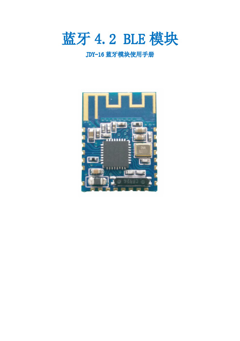
JDY-16蓝牙4.2模块(JDY-16-V1.9
亿佰特nRF52810 BLE5.0 低功耗 蓝牙转串口模块E104-BT5010A使用手册

目录第一章概述 (4)1.1简介 (4)1.2特点功能 (4)1.3应用场景 (4)第二章规格参数 (6)2.1极限参数 (6)2.2工作参数 (6)第三章机械尺寸与引脚定义 (7)第四章功能说明 (9)4.1角色说明 (9)4.2主机 (9)4.3从机 (10)4.4电源模式 (10)4.5MAC地址绑定 (11)4.6广播 (11)4.7配置 (12)4.8数据指示 (12)4.9UUID说明 (12)4.10状态或事件打印 (13)第五章 AT指令 (14)5.1指令说明 (14)5.2错误代码 (14)5.3状态打印 (14)5.4指令表 (15)5.4.1 AT 测试指令 (15)5.4.2 AT+RESET 复位指令 (15)5.4.3 AT+RESTORE 恢复出厂指令 (15)5.4.4 AT+BAUD串口波特率 (15)5.4.5 AT+PARI串口检验位 (16)5.4.6 AT+ROLE蓝牙角色 (16)5.4.7 AT+DEVMANUF 修改厂商名称 (17)5.4.8 AT+DEVSERIAL 修改设备串号 (17)5.4.9 AT+DEVMODEL 修改产品型号 (17)5.4.10 AT+DEVHWER 修改硬件版本 (18)5.4.11 AT+DEVSWVER 修改软件版本 (18)5.4.12 AT+DEVID 修改设备ID (18)5.4.13 AT+ADV广播使能 (18)5.4.14 AT+ADVDAT广播数据 (19)5.4.15 AT+ADVINTV广播间隙 (19)5.4.16 AT+IBCNUUID iBeacon UUID指令 (19)5.4.17 AT+MAJOR iBeacon Major指令 (20)5.4.18 AT+MINOR iBeacon Minor指令 (20)5.4.19 AT+IPWR 修改ibeacn tx_power (20)5.4.20 AT+NAME广播设备名 (21)5.4.21 AT+CONPARAMS 连接间隙配置 (21)5.4.22 AT+DISCON断开连接指令 (21)5.4.23 AT+DATDLY数据输出延迟 (22)5.4.24 AT+MAC本地MAC地址 (22)5.4.25 AT+PEERMAC连接设备MAC (22)5.4.26 AT+BOND绑定使能 (23)5.4.27 AT+BONDMAC添加绑定MAC地址 (23)5.4.28 AT+BONDDEL 删除绑定指定的MAC地址 (23)5.4.29 AT+SCAN广播扫描 (24)5.4.30 AT+SCANINTV扫描间隙 (24)5.4.31 AT+SCANWND扫描窗口 (24)5.4.32 AT+AUTOCONN 自动连接 (25)5.4.33 AT+CONN 指定连接 (25)5.4.34 AT+UUIDSVR128设置服务128bit UUID (25)5.4.35 AT+UUIDSVR蓝牙服务UUID (26)5.4.36 AT+UUIDCHARA1 SLAVE CHANNEL 特征UUID (26)5.4.37 AT+UUIDCHARA2 MAST CHANNEL特征UUID指令 (26)5.4.38 AT+VER 查询软件版本号 (26)5.4.39 AT+AUTH 空中配置认证密码 (27)5.4.40 AT+UPAUTH 修改空中认证密码 (27)5.4.41 AT+PWR 发射功率 (27)5.4.42 AT+ONSLEEP上电睡眠 (28)5.4.43 AT+DISCSLEEP连接断开后进入睡眠 (28)5.4.44 AT+SLEEP 立即进入睡眠指令 (28)5.4.45 AT+LOGMSG运行状态输出 (28)第六章快速使用 (30)6.1配置模式快速使用指南 (30)6.1.1 串口配置 (30)6.1.2 空中配置 (30)6.2数据传输 (32)6.2.1 数据透传 (32)第七章硬件设计 (34)第八章常见问题 (35)8.1传输距离不理想 (35)8.2模块易损坏 (35)8.3误码率太高 (35)第九章焊接作业指导 (36)9.1回流焊温度 (36)9.2回流焊曲线图 (37)第十章相关型号 (38)第十一章批量包装方式 (39)修订历史 (40)关于我们 (40)第一章概述1.1简介E104-BT5010A是一款基于蓝牙协议5.0版本的串口转BLE蓝牙主从一体模块,体积小、功耗低,工作在2.4GHz频段。
ZM5825 系列 Wi-Fi+BLE 模组数据手册说明书
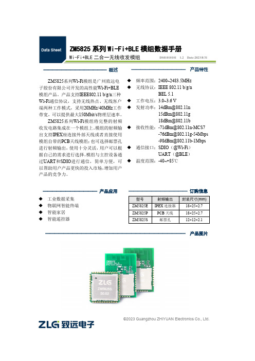
©2023 Guangzhou ZHIYUAN Electronics Co., Ltd.ZM5825系列Wi-Fi+BLE 模组数据手册Wi-Fi+BLE 二合一无线收发模组DS01010101 1.2 Date:2023/8/31———————————— 产品特性 ◆ 频率范围:2400~2483.5MHz ◆ 无线协议:IEEE 802.11 b/g/n BEL 5.1 ◆ 工作电压:3.0~3.6 V◆ 发射功率:************************** *************◆ 接收性能:************************************************************◆ 通信接口:SDIO (@Wi-Fi )UART (@BLE ) ◆ 温度范围:-40~+85℃————————————— 订购信息型号 射频输出 封装尺寸(mm) ZM5825E IPEX 连接器 18×25×2.7 ZM5825P PCB 天线 18×25×2.7 ZM5825S邮票孔12×12×2.1—————————————— 概述 ZM5825系列Wi-Fi 模组是广州致远电子股份有限公司开发的高性能Wi-Fi+BLE 模组产品。
产品支持IEEE802.11 b/g/n 三种Wi-Fi 通信协议,支持无线热点、无线客户端两种工作模式,采用20MHz/40MHz 工作带宽,可以提供最大150Mbit/s 物理层速率。
ZM5825系列Wi-Fi 模组将完整的射频收发电路集成在一个模组上。
模组的射频输出支持IPEX 座连接外部天线或者直接使用模组自带的PCB 天线模组;也可选择邮票孔进行射频输出,使用十分灵活,用户可以根据自己的需求进行选择。
模组与主控设备通过UART 和SDIO 进行通信,简单方便,可以帮助用户产品更快的投入市场,增加用户产品的竞争力。
信驰达 低功耗蓝牙(BLE)模块及标准透传协议 说明书

低功耗蓝牙(BLE)模块及标准透传协议协议版本:V5.20u(透传+直驱)更新日期:2021年10月29日版本更新记录文档日期更新内容2021/10/29 ✓第一次发布注:1、文档会不定期优化更新,在使用此文档前,请确保是最新版本;2、获取最新协议或文档,请到信驰达科技官方网址下载。
目录版本更新记录 (2)目录 (3)⚫ 概述 (5)⚫ 工作模式示意图 (7)⚫ 封装尺寸及脚位定义 (8)⚫ 串口透传协议说明(桥接模式) (10)⚫ BLE协议说明(APP接口) (12)➢ 设备信息【服务UUID:0x180A】 (12)➢ 串口数据通道【服务UUID:0xFFE0】 (12)➢ 蓝牙数据通道【服务UUID:0xFFE5】 (13)➢ 防劫持密钥【服务UUID:0xFFC0】 (13)➢ 模块参数设置【服务UUID:0xFF90】 (14)➢ 可编程IO(3路)【服务UUID:0xFFF0】 (17)➢ 定时翻转输出(2路)【服务UUID:0xFFF0】 (18)➢ 电平脉宽计数【服务UUID:0xFFF0】 (19)➢ 掉电保存设置【服务UUID:0xFFF0】 (20)➢ ADC输入(1路)【服务UUID:0xFFD0】 (20)➢ PWM输出(2路)【服务UUID:FFB0】 (21)⚫ 串口AT指令 (23)➢ 获取模块版本号 (23)➢ 连接间隔设定 (23)➢ 获取连接间隔 (23)➢ 获取模块名称 (23)➢ 模块重命名 (24)➢ 获取波特率 (24)➢ 波特率设定 (24)➢ 获取物理地址MAC (24)➢ 设置模块MAC地址 (24)➢ 广播周期设定 (25)➢ 获取广播周期 (25)➢ 附加自定义广播内容 (25)➢ 获取附加自定义广播内容 (25)➢ 定义产品识别码 (25)➢ 查看产品识别码 (26)➢ 发射功率设定 (26)➢ 获取发射功率 (26)➢ EN脚内部使能 (26)➢ EN脚内部使能状态查询 (26)➢ 修改透传服务UUID (27)➢ 修改BLE速率 (27)➢ 查看BLE速率 (28)➢ RSSI信号强度输出 (28)➢ RTC设定与获取 (28)➢ 数据延时设定 (28)➢ 获取数据延时 (29)➢ 获取模块连接密码 (29)➢ 设置模块连接密码 (29)➢ 串口回显设置/查询 (30)➢ 配对开关设置/查询 (30)➢ 配对超时设置/查询 (30)➢ 配对密码设置/查询 (31)➢ 配对列表查询/删除 (31)➢ 软件复位 (31)➢ 恢复出厂密码 (31)➢ 深度恢复 (32)AT指令表 (32)⚫ 广播数据设置 (35)⚫ 系统复位与恢复 (36)⚫ IOS APP编程参考 (37)⚫ 用USB Dongle及BTool测试 (39)➢ 连接BLE模块 (39)➢ 测试透传功能 (40)⚫ 主机参考代码(透传) (43)⚫ 联系我们 (44)附录A:模块硬件规格说明 (45)附录B:功耗测试截图 (47)⚫概述模块可以工作在桥接模式(透传传输模式)和直驱模式。
亿佰特 E104-BT52 BLE5.0低功耗贴片型蓝牙转串口模块规格书说明书

E104-BT52/E104-BT52X产品规格书DA14531BLE5.0低功耗贴片型蓝牙转串口模块目录第一章概述 (3)1.1简介 (3)1.3应用场景 (4)第二章规格参数 (4)2.1极限参数 (4)2.2工作参数 (4)第三章机械尺寸与引脚定义 (6)第四章基本应用 (8)4.1推荐电路 (8)第五章功能说明 (9)5.1角色说明 (9)5.2电源模式 (10)5.3数据传输模式 (10)5.4MAC地址绑定 (11)5.5广播 (11)5.6配置 (12)5.7数据指示 (12)5.8UUID说明 (13)5.9状态或事件打印 (13)第六章AT指令 (14)6.1指令说明 (14)6.2错误代码 (14)6.3状态打印 (14)6.4指令表 (14)第七章快速使用 (28)7.1配置模式快速使用指南 (28)7.2数据传输 (30)第八章常见问题 (32)8.1传输距离不理想 (32)8.2模块易损坏 (32)8.3误码率太高 (33)第九章焊接作业指导 (34)9.1回流焊温度 (34)9.2回流焊曲线图 (34)第十章相关型号 (35)第十一章批量包装方式 (36)修订历史 (37)关于我们 (37)第一章概述1.1简介E104-BT52/E104-BT52X是一款基于蓝牙协议5.0版本的串口转BLE蓝牙主从一体模块,体积小、功耗低,工作在2.4GHz 频段。
E104-BT52/E104-BT52X模块是成都亿佰特电子科技有限公司基于dialog的DA14531芯片研发,该模块使用通用的AT指令设置参数,操作简单快捷。
模块仅支持蓝牙主机、从机和观察者模式,模块在功能上支持低功耗广播、数据透传、空中配置。
模块可广泛应用于智能穿戴、家庭自动化、家庭安防、个人保健、智能家电、配饰与遥控器、汽车、照明、工业互联网、智能数据采集、智能控制等领域。
最大支持波特率460800bps的数据传输。
hac-embee-a11n 2.4g 低功耗无线数传模块(zigbee)用户手册说明书
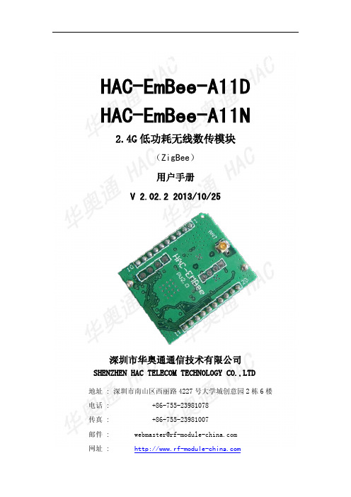
HAC-EmBee-A11D HAC-EmBee-A11N2.4G低功耗无线数传模块(ZigBee)用户手册V 2.02.2 2013/10/25深圳市华奥通通信技术有限公司SHENZHEN HAC TELECOM TECHNOLOGY CO.,LTD地址 : 深圳市南山区西丽路4227号大学城创意园2栋6楼电话 : +86-755-23981078传真 : +86-755-23981007邮件:*****************************网址 : HAC EmBee ZigBee Series 深圳市华奥通通信技术有限公司高性能✧20dbm可视距离2.8km✧7dbm可视距离850m 低功耗✧20dbm发射电流145mA,接收电流38mA,休眠电流3uA✧7dbm发射电流42mA,接收电流29mA,休眠电流3uAMESH网络✧自动组网,自动路由,自动愈合✧点对点,点对多点传输✧最多高达16跳传输 使用简单✧AT命令✧API命令✧API远程AT命令✧透明传输符合标准✧Zigbee 2007 Pro✧A11 Profile高可靠性✧DSSS O-QPSK调制方式✧CSMA-CA 自动退避机制✧重发与应答机制高安全性✧网络层AES加密✧应用层AES加密目录1 EmBee模块 (6)1.1 EmBee模块尺寸及管脚顺序 (6)1.2 模块管脚分布 (7)1.3 模块性能参数 (8)1.3.1 HAC-EmBee-A11N参数 (8)1.3.2 HAC-EmBee-A11D参数 (9)2 EmBee模块操作 (10)2.1 UART串口介绍 (10)2.2 通信协议 (10)2.2.1 透明传输模式 (10)2.2.2 API传输模式 (11)2.3 AT命令模式 (11)2.3.1 进入AT命令模式 (12)2.3.2 发送AT命令 (12)2.3.3 AT命令响应 (12)2.3.4 退出AT命令模式 (13)2.4 回环功能 (13)2.4.1 透传模式的回环 (13)2.4.2 API模式的回环 (13)3 API操作 (14)3.1 API帧格式 (14)3.2 API帧 (15)3.2.1 AT命令帧(立即生效) (15)3.2.2 AT命令帧(不立即生效) (16)3.2.3 AT命令响应帧 (17)3.2.4 传输请求帧 (18)3.2.5 应用层可选的传输请求帧 (19)3.2.6 传输状态帧 (21)3.2.1 数据接收指示帧(AO=0) (22)3.2.2 数据接收指示帧(AO=1) (23)3.2.3 I/O接收指示 (24)3.2.4 节点发现指示 (26)3.2.5 模块状态指示帧 (28)3.2.6 远端AT命令请求帧 (29)3.2.7 远端AT命令响应帧 (30)4 AT命令 (32)4.1 地址命令 (32)4.2 网络命令 (34)4.3 射频参数命令 (36)4.4 串口参数命令 (37)4.5 I/O参数命令 (38)4.6 诊断参数命令 (41)4.7 AT命令参数 (42)4.8 休眠命令 (42)4.9 命令执行 (43)5 数字I/O和模拟I/O (45)5.1 本地I/O (45)5.1.1 AT命令模式下读取本地I/O电平值和采样值 (45)5.1.1 AT命令模式下配置本地I/O (46)5.1.2 API模式下配置本地I/O (47)5.2 远端I/O (47)5.2.1 API模式下配置远端I/O (47)6 EmBee ZigBee网络 (48)6.1 协调器 (48)6.2 路由器 (49)6.3 终端设备 (49)6.3.1 子节点与父节点关系 (50)6.3.2 子节点容量 (50)6.4 子节点工作过程 (51)6.5 父节点工作过程 (51)1EmBee模块1.1EmBee模块尺寸及管脚顺序EmBee模块的外形结构如下:管脚顺序从PIN1开始,逆时针依次至PIN20。
亿佰特双模蓝牙模块V4.2协议模块E104-BT40使用手册

目录第一章概述 (2)1.1产品简介 (2)1.2特点功能 (2)1.3应用场景 (2)第二章规格参数 (2)2.1极限参数 (2)2.2工作参数 (3)第三章机械尺寸与引脚定义 (4)第四章快速使用 (5)4.1快速使用指南 (5)4.2空中配置 (6)4.3数据传输 (8)4.2.1 SPP数据透传 (8)4.2.2 BLE数据透传 (9)4.4其他 (11)第五章功能说明 (11)5.1配置 (11)5.2MAC地址绑定 (11)5.3状态或事件打印 (11)5.4经典蓝牙配对 (11)5.5UUID说明 (12)5.6打包机制 (12)第六章 AT指令 (12)第七章硬件设计 (24)第八章常见问题 (25)9.1传输距离不理想 (25)9.2 模块易损坏 (25)9.3误码率太高 (25)第九章焊接作业指导 (26)9.1回流焊温度 (26)9.2回流焊曲线图 (26)第十章批量包装方式 (27)修订历史 (27)关于我们 (27)第一章概述1.1 产品简介E104-BT40模块是一款基于蓝牙4.2+3.0版本的串口转双模蓝牙从机模块,即低功耗蓝牙BLE与经典蓝牙SPP Profile,可在BLE与经典蓝牙之间自由切换,工作在2.4GHz频段。
E104-BT40模块使用通用AT指令设置参数,操作简单快捷。
模块仅支持蓝牙从机角色,通过该模块可以使传统的低端串口设备或者MCU控制的设备进行无线数据传输。
是一款低成本,简单,可靠的数据传输模块。
1.2 特点功能●支持蓝牙Bluetooth Specification V4.2 +3.0协议;●支持AT指令配置;●支持BLE;●支持SPP 3.0;●GPIO输入/输出;●2路PWM输出●串口缓存249字节●有效通讯距离 30米以上●支持全球免许可ISM 2.4GHz频段;●支持1~2Mbps空中速率;●自带PCB板载天线,无需外接天线。
1.3 应用场景●蓝牙无线数据传输●无线抄表无线传感●智能家居、工业控制●工业遥控、遥测●智能楼宇、智能建筑●自动化数据采集●健康传感器●汽车检测设备●智能机器人第二章规格参数2.1 极限参数2.2 工作参数第三章机械尺寸与引脚定义①用户可配置输出IO默认输出低电平,设置后,下次上电后依然按照设置的参数输出电平;②PWM默认关闭,设置后,下次上电后依然按照设置的参数输出PWM;③MODE引脚切换模式仅在建立连接后有效第四章快速使用调试/测试推荐软件:●PC端串口工具-SSCOM.exe或者AccessPort●手机端ble调试APP BLE-nRF connect 经典蓝牙-蓝牙串口助手4.1快速使用指南●模块未连接时均为AT指令模式,建立连接时,模块进入透传模式,可通过拉低MODE引脚进入AT指令模式,拉高MODE引脚返回透传模式。
Espressif ESP32-C6 系列芯片技术规格书说明书

ESP32-C6系列芯片技术规格书搭载RISC-V32位单核处理器的极低功耗SoC2.4GHz Wi-Fi6(802.11ax)、Bluetooth®5(LE)、Zigbee及Thread(802.15.4)芯片封装内可叠封4MB flash30或22个GPIO,丰富的外设QFN40(5×5mm)或QFN32(5×5mm)封装包括:ESP32-C6ESP32-C6FH4版本1.0乐鑫信息科技版权©2023产品概述ESP32-C6是一款支持2.4GHz Wi-Fi 6、Bluetooth 5、Zigbee 3.0及Thread 1.3系统级芯片(SoC),集成了一个高性能RISC-V 32位处理器和一个低功耗RISC-V 32位处理器、Wi-Fi 、Bluetooth LE 、802.15.4基带和MAC 、RF 模块及外设等。
Wi-Fi 、蓝牙及802.15.4共存,共用同一个天线。
芯片的功能框图如下图所示。
Modules having power in specific power modes:ActiveActive and Modem-sleep Active, Modem-sleep, Light-sleep;optional in Light-sleepAll modesESP32-C6功能框图更多关于功耗的信息,请参考章节3.9低功耗管理。
产品特性Wi-Fi•工作在2.4GHz频段,1T1R•工作信道中心频率范围:2412~2484MHz•支持IEEE802.11ax协议:–仅20MHz非接入点工作模式(20MHz-onlynon-AP mode)–MCS0~MCS9–上行、下行正交频分多址接入(OFDMA),特别适用于高密度应用下的多用户并发传输–下行多用户多输入多输出(MU-MIMO),提升网络容量–波束成形接收端(Beamformee),提升信号质量–信道质量指示(Channel quality indication,CQI)–双载波调制(dual carrier modulation,DCM),提高链路稳定性–空间复用(Spatial reuse),提升网络容量–目标唤醒时间(TWT),提供更好的节能机制•完全兼容IEEE802.11b/g/n协议:–支持20MHz和40MHz频宽–数据速率高达150Mbps–无线多媒体(WMM)–帧聚合(TX/RX A-MPDU,TX/RX A-MSDU)–立即块确认(Immediate Block ACK)–分片和重组(Fragmentation and defragmen-tation)–传输机会(Transmission opportunity,TXOP)–Beacon自动监测(硬件TSF)–4×虚拟Wi-Fi接口–同时支持基础结构型网络(InfrastructureBSS)Station模式、SoftAP模式、Station+SoftAP模式和混杂模式请注意ESP32-C6在Station模式下扫描时,SoftAP信道会同时改变–天线分集–802.11mc FTM蓝牙•低功耗蓝牙(Bluetooth LE):通过Bluetooth5.3认证•Bluetooth mesh•高功率模式(20dBm)•速率支持125Kbps、500Kbps、1Mbps、2Mbps •广播扩展(Advertising Extensions)•多广播(Multiple Advertisement Sets)•信道选择(Channel Selection Algorithm#2)•功率控制(LE Power Control)•Wi-Fi与蓝牙共存,共用同一个天线IEEE802.15.4•兼容IEEE802.15.4-2015协议•工作在2.4GHz频段,支持OQPSK PHY•数据速率:250Kbps•支持Thread1.3•支持Zigbee3.0CPU和存储•高性能RISC-V处理器:–时钟频率:最高160MHz–四级流水线架构–CoreMark®得分:441.32CoreMark;2.76CoreMark/MHz(160MHz)•低功耗RISC-V处理器:–时钟频率:最高20MHz–二级流水线架构•L1cache:32KB•ROM:320KB•HP SRAM:512KB•LP SRAM:16KB•支持的SPI协议:SPI、Dual SPI、Quad SPI、QPI 接口在芯片封装外连接多个flash和其他SPI设备•通过cache加速flash访问•支持flash在线编程(ICP)高级外设接口•30×GPIO口(QFN40)或22×GPIO口(QFN32)•模拟接口:–1×12位SAR ADC,多达7个通道–1×温度传感器•数字接口:–2×UART–1×低功耗UART(LP UART)–2×SPI接口用于连接flash–1×通用SPI接口–1×I2C–1×低功耗I2C(LP I2C)–1×I2S–1×脉冲计数控制器–1×USB串口/JTAG控制器–2×TWAI®控制器,兼容ISO11898-1(CAN 规范2.0)–1×SDIO2.0从机控制器–LED PWM控制器,多达6个通道–1×电机控制脉宽调制器(MCPWM)–1×红外遥控器(TX/RX)–1×并行IO接口(PARLIO)–通用DMA控制器(简称GDMA),3个接收通道和3个发送通道–事件任务矩阵(ETM)•定时器:–1×52位系统定时器–2×54位通用定时器–3×数字看门狗定时器–1×模拟看门狗定时器功耗管理•通过选择时钟频率、占空比、Wi-Fi工作模式和单独控制内部器件的电源,实现精准电源控制•针对典型场景设计的四种功耗模式:Active、Modem-sleep、Light-sleep、Deep-sleep•Deep-sleep模式下功耗低至7µA•Deep-sleep模式下低功耗存储器(LP memory)仍保持工作安全机制•安全启动-内部和外部存储器的权限控制•Flash加密-加密和解密存储器•4096位OTP,用户可用的高达1792位•可信执行环境控制器(TEE)和访问(地址)权限管理(APM)•加密硬件加速器:–AES-128/256(FIPS PUB197)–ECC–HMAC–RSA–SHA–数字签名–Hash(FIPS PUB180-4)•片外存储器加密与解密(XTS_AES)•随机数生成器(RNG)RF模块•天线开关、射频巴伦(balun)、功率放大器、低噪声放大器•802.11b传输功率高达+21dBm•802.11ax传输功率高达+19.5dBm•低功耗蓝牙接收器灵敏度(125Kbps)高达-106dBm应用低功耗芯片ESP32-C6专为物联网(IoT)设备而设计,应用领域包括:•智能家居•工业自动化•医疗保健•消费电子产品•智慧农业•POS机•服务机器人•音频设备•通用低功耗IoT传感器集线器•通用低功耗IoT数据记录器目录产品概述2产品特性3应用51ESP32-C6系列型号对比12 1.1命名规则12 1.2型号对比122管脚13 2.1管脚布局13 2.2管脚概述15 2.3IO管脚182.3.1IO MUX和GPIO管脚功能182.3.2LP IO MUX功能212.3.3模拟功能212.3.4GPIO和LP GPIO的限制23 2.4模拟管脚24 2.5电源252.5.1电源管脚252.5.2电源管理252.5.3芯片上电和复位26 2.6Strapping管脚272.6.1SDIO输入采样沿和输出驱动沿控制282.6.2芯片启动模式控制282.6.3ROM日志打印控制282.6.4JTAG信号源控制29 2.7芯片与flash的管脚对应关系303功能描述31 3.1CPU和存储313.1.1HP CPU313.1.2LP CPU313.1.3片上存储313.1.4封装外flash323.1.5存储器映射323.1.6Cache333.1.7TEE控制器333.1.8访问权限管理(APM)333.1.9超时保护33 3.2系统时钟333.2.1CPU时钟333.2.2低功耗时钟343.3模拟外设343.3.1模/数转换器(ADC)343.3.2温度传感器34 3.4数字外设343.4.1通用异步收发器(UART)343.4.2串行外设接口(SPI)353.4.3I2C接口353.4.4I2S接口353.4.5脉冲计数控制器(PCNT)363.4.6USB串口/JTAG控制器363.4.7TWAI®控制器363.4.8SDIO2.0从机控制器373.4.9LED PWM控制器373.4.10电机控制脉宽调制器(MCPWM)373.4.11红外遥控器(RMT)383.4.12并行IO(PARLIO)控制器383.4.13通用DMA控制器(GDMA)383.4.14事件任务矩阵(ETM)38 3.5射频383.5.1 2.4GHz接收器393.5.2 2.4GHz发射器393.5.3时钟生成器39 3.6Wi-Fi393.6.1Wi-Fi射频和基带393.6.2Wi-Fi MAC403.6.3联网特性41 3.7低功耗蓝牙413.7.1低功耗蓝牙PHY413.7.2低功耗蓝牙链路控制器41 3.8802.15.4423.8.1802.15.4PHY423.8.2802.15.4MAC42 3.9低功耗管理42 3.10定时器433.10.1系统定时器433.10.2通用定时器433.10.3看门狗定时器43 3.11加密/安全组件443.11.1AES加速器(AES)443.11.2ECC加速器(ECC)453.11.3HMAC加速器(HMAC)453.11.4RSA加速器(RSA)453.11.5SHA加速器(SHA)453.11.6数字签名(DS)463.11.7片外存储器加密与解密(XTS_AES)463.11.8随机数发生器(RNG)463.12外设管脚分配474电气特性50 4.1绝对最大额定值50 4.2建议电源条件50 4.3VDD_SPI输出特性50 4.4直流电气特性(3.3V,25°C)51 4.5ADC特性51 4.6功耗特性524.6.1Active模式下的RF功耗524.6.2其他功耗模式下的功耗53 4.7可靠性535射频特性55 5.1Wi-Fi射频555.1.1Wi-Fi射频发射器(TX)特性555.1.2Wi-Fi射频接收器(RX)特性56 5.2低功耗蓝牙射频585.2.1低功耗蓝牙射频发射器(TX)特性585.2.2低功耗蓝牙射频接收器(RX)特性59 5.3802.15.4射频615.3.1802.15.4射频发射器(TX)特性625.3.2802.15.4射频接收器(RX)特性626封装637相关文档和资源64附录A–ESP32-C6管脚总览65修订历史67表格1-1ESP32-C6系列芯片对比12 2-1QFN40封装管脚概述16 2-2QFN32封装管脚概述17 2-3QFN40封装IO MUX管脚功能19 2-4QFN32封装IO MUX管脚功能19 2-5LP IO MUX功能21 2-6模拟功能22 2-7模拟管脚24 2-8电源管脚25 2-9电压稳压器25 2-10上电和复位时序参数说明26 2-11Strapping管脚默认配置27 2-12Strapping管脚的时序参数说明27 2-13SDIO输入采样沿/输出驱动沿控制28 2-14芯片启动模式控制28 2-15ROM日志打印控制29 2-16JTAG信号源控制29 2-17QFN40封装芯片与封装外flash/PSRAM的管脚对应关系30 3-1外设和传感器管脚分配47 4-1绝对最大额定值50 4-2建议电源条件50 4-3VDD_SPI内部和输出特性50 4-4直流电气特性(3.3V,25°C)51 4-5ADC特性51 4-6ADC校准结果52 4-7Active模式下Wi-Fi(2.4GHz)功耗特性52 4-8Active模式下低功耗蓝牙功耗特性52 4-9Active模式下802.15.4功耗特性53 4-10Modem-sleep模式下的功耗53 4-11低功耗模式下的功耗53 4-12可靠性认证53 5-1Wi-Fi射频规格55 5-2频谱模板和EVM符合802.11标准时的发射功率55 5-3发射EVM测试55 5-4接收灵敏度56 5-5最大接收电平57 5-6接收邻道抑制57 5-7低功耗蓝牙射频规格58 5-8低功耗蓝牙-发射器特性-1Mbps58 5-9低功耗蓝牙-发射器特性-2Mbps58 5-10低功耗蓝牙-发射器特性-125Kbps59 5-11低功耗蓝牙-发射器特性-500Kbps59 5-12低功耗蓝牙-接收器特性-1Mbps595-13低功耗蓝牙-接收器特性-2Mbps60 5-14低功耗蓝牙-接收器特性-125Kbps61 5-15低功耗蓝牙-接收器特性-500Kbps61 5-16802.15.4射频规格61 5-17802.15.4发射器特性-250Kbps62 5-18802.15.4接收器特性-250Kbps62 7-1QFN40封装管脚总览65 7-2QFN32封装管脚总览66插图插图1-1ESP32-C6系列芯片命名规则12 2-1ESP32-C6管脚布局(QFN40封装,俯视图)13 2-2ESP32-C6管脚布局(QFN32封装,俯视图)14 2-3ESP32-C6电源管理26 2-4上电和复位时序参数图26 2-5Strapping管脚的时序参数图28 3-1地址映射结构32 6-1QFN40(5×5mm)封装63 6-2QFN32(5×5mm)封装631ESP32-C6系列型号对比1ESP32-C6系列型号对比1.1命名规则F H/N xflash ⼤⼩ (MB)flash 温度H:⾼温N:正常封装内 flash芯⽚系列图1-1.ESP32-C6系列芯片命名规则1.2型号对比表1-1.ESP32-C6系列芯片对比1更多关于芯片丝印和包装的信息,请参考小节6封装。
Zebra Technologies IH21 UHF RFID 手持读取器配件手册说明书

IH21 HANDHELD UHF RFID READER Accessories GuideACCESSORIESIH21-EPL-CT40IH21-EPL-CT50ePop-Loq Snap-On Adaptor for CT40Snaps easily on or off the mobile computer. Compatiblewith the homebase for terminal charging.ePop-Loq Snap-On Adaptor for CT60Snaps easily on or off the mobile computer. Compatiblewith the homebase for terminal charging.IH21 RFID READERSIH21A0002IH21A0014IH21 Bluetooth®RFID ReaderWith ePop-Loq®, UHFAntenna, Trigger Handle,Battery, Battery Cover, noimager, red and black. ETSIIH21 BluetoothRFID ReaderWith ePop-Loq, UHFAntenna, Trigger Handle,Battery, Battery Cover, noimager, red and black. FCCIH21-EPL-EDA50IH21-EPL-D75EePop-Loq Snap-On Adaptor for ScanPal™ EDA50Snaps easily on or off the mobile computer. Compatiblewith the homebase for terminal charging.ePop-Loq Snap-On Adaptor for D75eSnaps easily on or off the mobile computer. Compatiblewith the homebase for terminal charging.IH21 Handheld UHF RFID Reader Accessories Guide | 2ScanPal is a trademark or registered trademark of Honeywell International Inc. Bluetooth is a trademark or registered trademark of Bluetooth SG, Inc.ePop-Loq is a trademark or registered trademark of Technology Solutions (UK) Ltd.All other trademarks are the property of their respective owners.IH21 Handheld UHF RFID Reader Accessories Guide | Rev B | 06/19© 2019 Honeywell International Inc.For more informationHoneywell Safety and Productivity Solutions 9680 Old Bailes RoadFort Mill, SC 29707800-582-4263 IH21-CB-1IH21-QBC-1318-060-001IH21 Docking Homebase Kit includes power supply unit and mini USB lead. 4-Slot Battery Charger Must order 12V 4A power supply and power cord separately. Individual charge status LED for each battery slot in addition to a main power supply status LED.Spare Battery For IH21 RFID reader, 3.7V 2300 mAh.。
VIVARES ZB O SENS 220-240 无线传感器产品说明书
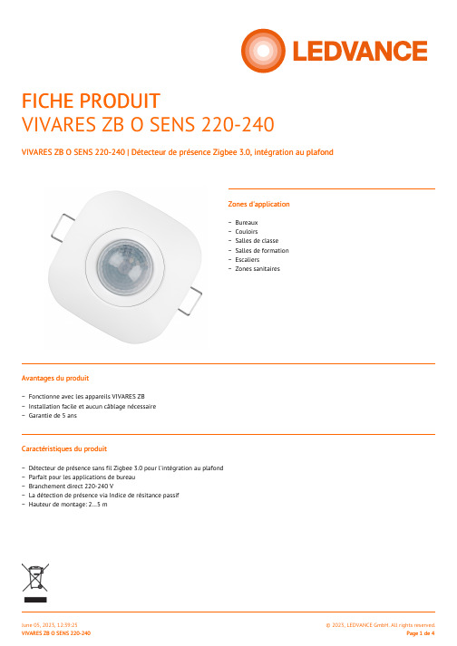
Zones d'applicationFICHE PRODUITVIVARES ZB O SENS 220-240VIVARES ZB O SENS 220-240 | Détecteur de présence Zigbee 3.0, intégration au plafondAvantages du produitCaractéristiques du produitBureaux −Couloirs−Salles de classe −Salles de formation −Escaliers−Zones sanitaires−Fonctionne avec les appareils VIVARES ZB −Installation facile et aucun câblage nécessaire −Garantie de 5 ans−Détecteur de présence sans fil Zigbee 3.0 pour l'intégration au plafond −Parfait pour les applications de bureau −Branchement direct 220-240 V−La détection de présence via Indice de résitance passif −Hauteur de montage: 2…5 m−DONNÉES TECHNIQUESDONNÉES ÉLECTRIQUESPuissance nominale1,84 W Tension nominale220…240 VFréquence du réseau50…60 Hz Tension maximum entre Phase/Neutre 2 kVDIMENSIONS ET POIDSLongueur85.00 mm Largeur85.00 mm Largeur (y compris les luminaires ronds)85.00 mm Hauteur64.00 mm Hauteur (luminaires cycliques inclus)64.00 mmPoids du produit120,00 gCOULEURS ET MATÉRIAUXCouleur du produit BlancMatériau de fermeture Polycarbonate (PC)TEMPÉRATURES ET CONDITIONS DE FONCTIONNEMENTPlage de température ambiante-20…+50 °C 1) Plage de température au point Tc+10…+35 °C Humidité relative10…85 %1) Max. plage de température valable uniquement pour la sécurité des composantsCAPACITÉSGradable Non Gradateur Zigbee 3.0 Hauteur maximale d'installation 5 mAngle de détection90 °Type d'installation EncastréPlage du transmetteur10 m 1)1) Pour une installation intérieureCERTIFICATS ET NORMESLabels et agréments CE / RoHSNormes Conformément à EN 60669-1 / Conformément à EN 60669-2-1 / Conformément à EN 60669-2-5 / Conformément à EN 61000-3-2 / Acc. to EN 50663 / Conformément à EN 300328 / Conformément à EN 301489Type de protection IP20DONNÉES LOGISTIQUESPlage de température de stockage-10…+65 °CTÉLÉCHARGEMENTSDocuments and certificatesUser instructionInstallation guidePackaging insertDeclarations Of Conformity CETender textsOffresDONNÉES LOGISTIQUESCode produit Unité d'emballage (Pièces/Unité)Dimensions (longueur x largeur x hauteur)Poids approximatif Volume4058075544222Etui carton fermé1111 mm x 110 mm x 86 mm167.00 g 1.05 dm³4058075544239Carton de regroupement10528 mm x 243 mm x 120 mm2066.00 g15.40 dm³Le code produit mentionné décrit la petite quantité d’unité qui peut être commandée. Une unité peut contenir un ou plusieurs produits. Lorsque vous passez la commande, merci de bien vouloir entrer une unité ou un multiple d’une unité.DÉTAILS COMPLÉMENTAIRESAVERTISSEMENTSous réserve de modifications. Sauf erreur ou omission. Veillez à toujours utiliser la version la plus récente.。
低功耗蓝牙4.0(BLE)主从通信模块及主透传协议
60*1000/30 = 2K 40*1000/30 = 1.3K 20*1000/30 = 666byte
表 3:通讯速率参考模式
注:可以根据实际应用设计特定的通讯模式,串口包的长度可以设计在 80byte < L < 200byte 之间(大包传输),根据 BLE 协议有以下关系: 当取 L<80 时,TS >= T; 当取 80<L<160 时,TS >= T*2; 当取 160<L<200 时,TS >= T*3; 满足以上条件的转发模式都是相对安全的,其中取 TS=T,TS=T*2,TS=T*3,可用但不推 荐,丢包率较高, 必须加入校验重发机制。也就是说,当串口包采用 80byte < L < 200byte 的大包时,串口数据可以一次性传递给模块,但需要预留模块通过蓝牙发送数据的时间, 否则会出现追尾现象。如:在连接间隔设置为 T=20ms 时,如串口数据包长度选择 L=200, 则 TS 必须大于 T*3 = 60ms,取 TS=70ms 是比较合理的选择。 串口数据包的大小可以不定长,长度可以是 200 字节以下的任意值,同样满足以上条 件即可。为最大效率地使用通讯有效载荷,同时又避免通讯满负荷运行,推荐使用 20, 40,60 字节长度的串口数据包。
深圳市信驰达科技பைடு நூலகம்限公司 4
� 概述
低功耗蓝牙模块主透传协议是针对低功耗蓝牙模块从透传协议设计的, 通过本协议模 块可替代手机设备与从透传协议模块连接,实现透传功能或直驱控制功能。此协议模块 可用作从透传协议模块开发过程中的辅助工具。 BLE 主透传模块 (以下简称 MTTM ) 可以工作在透传模式 (TTM ) 或指令模式 (CM) 。 主透传模块上电启动后,处于待机模式( SBM) ,此时处于空闲状态,无睡眠,需要 用户通过 AT 指令控制模块连接从设备。在成功与从设备建立链接后,主模块会自动查找 从设备的透传通道,如果从设备属于信驰达 BLE 从透传协议模块(以下简称 STTM ) , 主 模块默认进入透传模式,否则默认进入指令模式。 透传模式下,用户 CPU 可以通过主模块的通用串口与从模块进行双向通讯。从主模 块串口输入的数据将转发到从模块,并从其串口输出;从从模块串口输入的数据将转发 到主模块,并从其串口输出,从而实现双向透明传输,用户数据的具体含义由上层应用 程序自行定义。 指令模式下,用户 CPU 可以通过主模块的读写指令直接控制信驰达从模块的直驱功 能。此模式下功能开发中,敬请期待。
蓝牙(BLE)模块及协议
4
深圳市信驰达科技有限公司
SHENZHEN RF STAR TECHNOLOGY CO.,LTD.
V2.2u
2013/12/26
移植最新 TI 官方 BLE 协议栈 v1.3.2 底层,优化对 IO7 的兼容性 广播中的数据自动加载 ADC 采集结果,或者 PWM 输出状态,都为四个
字节。自动加载最后操作的通道数据(ADC/PWM); 增加两路电平脉宽计数功能。IO4,O5,两个 IO 支持电平计数功能; 添加发射功率,产品识别码,自定义广播内容,广播周期服务通道设置
模块做为智能手机外设的桥梁,使得主机端应用开发异常简单。在桥接模式下(串口), 用户的现有产品或者方案配合此透传模块,能十分方便地和移动设备(需支持蓝牙 4.0)相互通
2
深圳市信驰达科技有限公司
SHENZHEN RF STAR TECHNOLOGY CO.,LTD.
讯,实现超强的智能化控制和管理。而在直驱模式下,用户直接使用模块扩展简单外围,就 能快速设计出方案甚至产品,以最低成本最高效地推出特有的个性化移动设备新外设。
出状态值(掉电保存);
支持 PWM 频率自定义(61.036 Hz <=f <= 8 kHz,默认 120Hz)
广播内容提示模块系统状态,包括电池电量,自定义设备识别码,四路 PWM 输出值,IO 状态等;
芯科科技 BGX220S 无线 Gecko Bluetooth Xpress 模块数据表

BGX220S 无线 Gecko Bluetooth Xpress 模块数据表BGX220S 是无线电缆替换模块,可通过串行接口消除 Bluetooth固件开发的复杂性,该串行接口可作为原始数据流运行,也可以通过抽象命令 API 来控制设备。
BGX220S 可通过 Xpress Bluetooth 移动库加强设备对设备电缆更换连接或与移动设备通信。
随着Bluetooth 5.2 的采用率日渐上升,该设备会将符合 Bluetooth 5.2标准的协议栈集成到适应未来需求的应用中。
BGX220S 模块是全面的解决方案,具有完全可升级的强大软件协议栈、全球范围内的法规认证,以及可尽量缩减和简化最终产品工程和开发工作的支持功能,从而帮助缩短产品上市时间。
BGX220S 适用于广泛的应用领域,包括:•健康、运动和健康设备•工业、家庭和楼宇自动化•智能手机、平板电脑和 PC 附件主要特点•Bluetooth 5.2 技术•Bluetooth 低功耗•内置天线•高达 6 dBm 的 TX 功率•在 1 Mbps 时,dBm BLE RX 灵敏度为-98.6•8 个 GPIO 引脚•I2C 主接口•输入引脚事件监控和响应•6.0 mm x 6.0 mmBGX220S Wireless Gecko Bluetooth Xpress Module Data SheetOrdering Information 1. Ordering InformationTable 1.1. Ordering InformationTable of Contents1. Ordering Information (2)2. System Overview (5)2.1 Block Diagram (5)2.2 EFR32BG22 SoC (6)2.3 Antenna (6)2.4 Power Supply (6)3. Electrical Characteristics (7)3.1 Absolute Maximum Ratings (7)3.2 General Operating Conditions (8)3.2.1 DC-DC Operating Limits (9)3.3 Power Consumption (10)3.4 RF Transmitter General Characteristics for the 2.4 GHz Band (11)3.5 RF Receiver General Characteristics for the 2.4 GHz Band (11)3.6 RF Receiver Characteristics for Bluetooth Low Energy in the 2.4 GHz Band 1 Mbps Data Rate (12)3.7 RF Receiver Characteristics for Bluetooth Low Energy in the 2.4 GHz Band 2 Mbps Data Rate (13)3.8 RF Receiver Characteristics for Bluetooth Low Energy in the 2.4 GHz Band 500 kbps Data Rate..143.9 RF Receiver Characteristics for Bluetooth Low Energy in the 2.4 GHz Band 125 kbps Data Rate..153.10 Non-Volatile Configuration Storage (16)3.11 High-Frequency Crystal (16)3.12 GPIO Pins (17)3.13 Typical Performance Curves (17)3.13.1 Antenna Typical Characteristics (18)4. Reference Diagrams (19)4.1 Typical Connections (19)5. 44-Pin SiP Module Device Pinout (20)6. Functional overview (22)6.1 Introduction (22)6.2 Communication Use Cases (22)6.3 Embedded Interface (22)6.4 Command Mode and Streaming Mode (22)6.5 Command API (23)6.6 GPIO Control (23)6.7 Device Configuration (23)6.8 Security Features (23)6.9 OTA (23)6.10 Direct Test Mode Support (23)7. Design Guidelines (24)7.1 Layout and Placement (24)7.2 Best Design Practices (27)7.3 Radio Performance vs. Carrier Board Size (29)7.4 Proximity to Other Materials (29)7.5 Proximity to Human Body (30)8. Package Specifications (31)8.1 Package Dimensions (31)8.2 Recommended PCB Land Pattern (33)8.3 Top Marking (34)9. Soldering Recommendations (35)10. Tape and Reel (36)11. Certifications (38)11.1 Certifications for Model BGM220S22A (38)12. Revision History (39)2. System Overview2.1 Block DiagramThe BGX220S module combines an energy-friendly MCU with a highly integrated radio transceiver in a SiP module with a robust, inte-grated antenna. This section gives a short introduction to the features of the module.Note that features in the module are not directly configurable in this pre-programmed product, and are instead controlled through the abstracted command and variable set.The block diagram for the BGX220S module is shown in the figure below. The wireless module includes the EFR32BG22 wireless Sys-tem on a Chip (SoC), required decoupling capacitors and inductors, 38.4 MHz crystal, RF matching circuit, and integrated antenna.Figure 2.1. BGX220S Block DiagramA simplified internal schematic for the BGX220S module is shown in Figure 2.2 BGX220S Module Schematic on page 5.VREGVDDEFR32BG22GPIO(0-7)IOVDDVREGDECOUPLERF_2G4ANT_OUT ANT_IN Figure 2.2. BGX220S Module Schematic2.2 EFR32BG22 SoCThe EFR32BG22 SoC features a 32-bit ARM Cortex M33 core, a 2.4 GHz high-performance radio, 512 kB of flash memory, a rich set of MCU peripherals, and various clock management and serial interfacing options. Consult the EFR32xG22 Wireless Gecko Reference Manual and the EFR32BG22 Data Sheet for details.Note that the Flash and other features in this product are not directly accessible, and are instead accessed through the product's ab-stracted command and variable set.2.3 AntennaBGX220S modules include an integral antenna on board with the characteristics detailed in the tables below.Table 2.1. Antenna Efficiency and Peak Gain2.4 Power SupplyThe BGX220S requires a single nominal supply level of 3.0 V to operate. All necessary decoupling and filtering components are inclu-ded in the module.3. Electrical CharacteristicsAll electrical parameters in all tables are specified under the following conditions, unless stated otherwise:•Typical values are based on T A=25 °C and VDD supply at 3.0 V, by production test and/or technology characterization.•Radio performance numbers are measured in conducted mode, based on Silicon Laboratories reference designs using output pow-er-specific external RF impedance-matching networks for interfacing to a 50 Ω antenna.•Minimum and maximum values represent the worst conditions across supply voltage, process variation, and operating temperature, unless stated otherwise.3.1 Absolute Maximum RatingsStresses beyond those listed below may cause permanent damage to the device. This is a stress rating only and functional operation of the devices at those or any other conditions beyond those indicated in the operation listings of this specification is not implied. Exposure to maximum rating conditions for extended periods may affect device reliability. For more information on the available quality and relia-bility data, see the Quality and Reliability Monitor Report at /support/quality/pages/default.aspx.Table 3.1. Absolute Maximum Ratings3.2 General Operating ConditionsThis table specifies the general operating temperature range and supply voltage range for all supplies. The minimum and maximum values of all other tables are specifed over this operating range, unless otherwise noted.Table 3.2. General Operating Conditions3.2.1 DC-DC Operating LimitsThe maximum supported voltage on the VDD supply pin is limited under certain conditions. Maximum input voltage is a function of tem-perature and the average load current over a 10-year lifetime. Figure 3.1 Lifetime average load current limit vs. Maximum input voltage on page 9 shows the safe operating region under specific conditions. Exceeding this safe operating range may impact the reliability and performance of the DC-DC converter.The average load current for an application can typically be determined by examining the current profile during the time the device is powered. For example, an application that is continuously powered which spends 99% of the time asleep consuming 2 µA and 1% of the time active and consuming 10 mA has an average lifetime load current of about 102 µA.A v e r a g e L i f e t i m e I L O A D (m A )Maximum V VREGVDD (V)6053.33.8Tj ≤ 105 °CFigure 3.1. Lifetime average load current limit vs. Maximum input voltageThe minimum input voltage for the DC-DC in EM0/EM1 mode is a function of the maximum load current, and the peak current setting.Figure 3.2 Transient maximum load current vs. Minimum input voltage on page 9 shows the max load current vs. input voltage for different DC-DC peak inductor current settings.M a x i m u m I L O A D (m A )Minimum V VREGVDD (V)6052.21.836I PEAK = 150 mA I PEAK = 90 mAFigure 3.2. Transient maximum load current vs. Minimum input voltage3.3 Power ConsumptionTable 3.3. Power Consumption3.4 RF Transmitter General Characteristics for the 2.4 GHz BandUnless otherwise indicated, typical conditions are: T A = 25 °C, VREGVDD = 3.0V. RF center frequency 2.45 GHz.Table 3.4. RF Transmitter General Characteristics for the 2.4 GHz Band3.5 RF Receiver General Characteristics for the 2.4 GHz BandUnless otherwise indicated, typical conditions are: T A = 25 °C, VREGVDD = 3.0V. RF center frequency 2.45 GHz.Table 3.5. RF Receiver General Characteristics for the 2.4 GHz BandTable 3.6. RF Receiver Characteristics for Bluetooth Low Energy in the 2.4 GHz Band 1 Mbps Data RateTable 3.7. RF Receiver Characteristics for Bluetooth Low Energy in the 2.4 GHz Band 2 Mbps Data RateTable 3.8. RF Receiver Characteristics for Bluetooth Low Energy in the 2.4 GHz Band 500 kbps Data RateTable 3.9. RF Receiver Characteristics for Bluetooth Low Energy in the 2.4 GHz Band 125 kbps Data Rate3.10 Non-Volatile Configuration StorageTable 3.10. Non-volatile Configuration Storage3.11 High-Frequency CrystalTable 3.11. High-Frequency Crystal3.12 GPIO PinsUnless otherwise indicated, typical conditions are: IOVDD = 3.0 V.Table 3.12. GPIO Pins3.13 Typical Performance CurvesTypical performance curves indicate typical characterized performance under the stated conditions.3.13.1 Antenna Typical CharacteristicsTypical BGX220S radiation patterns for the on-board chip antenna under optimal operating conditions are plotted in the figures that follow. Antenna gain and radiation patterns have a strong dependence on the size and shape of the application PCB the module is mounted on, as well as on the proximity of any mechanical design to the antenna.Top Left: Phi 0o, Top Right: Phi 90o, Bottom Left: Theta 90oFigure 3.3. BGX220S Typical 2D Antenna Radiation Patterns on 55 mm x 20 mm boardReference Diagrams 4. Reference Diagrams4.1 Typical ConnectionsThe BGX220S can be controlled over the UART interface as a peripheral to an external host processor. Typical power supply and host interface connections are shown in the figure below.Note that an external pull-up should not be placed on the reset pin.RESETnFigure 4.1. Typical Connection DiagramU A R T _T XN CD E C O U P L EN CU A R T _R XU A R T _R T SU A R T _C T SG P I O 5G P I O 6G P I O 7Figure 5.1. 44-Pin SiP Module Device Pinout Table 5.1. 44-Pin SiP Module Device Pinout44-Pin SiP Module Device Pinout6. Functional overview6.1 IntroductionThe BGX220S creates a Bluetooth 5.2 compliant Bluetooth Low Energy cable replacement interface, facilitating a Bluetooth Low Ener-gy link to a second embedded device or a mobile device. An embedded MCU controls the device and communicates across the Blue-tooth Low Energy link through a serial interface and control signals. Parameters stored in non-volatile memory and configurable through the serial interface adjust performance characteristics of the device. Silicon Labs offers iOS and Android mobile libraries for Bluetooth Xpress devices to speed mobile development and simplify communication with the device. This library also controls OTA management, facilitating secure and reliable updates to the device’s embedded stack.This functional overview does not cover each command supported by the command API. The complete command API specification is available at .6.2 Communication Use CasesThe BGX220S family facilitates two types of Bluetooth Low Energy communication links:•BGX-to-mobile•BGX-to-BGXIn the BGX-to-mobile communication use case, the BGX220S operates as a peripheral that is discoverable and connectable when con-figured to that state through either the command API or the pin states driven by the embedded MCU. Using the Xpress mobile library, mobile applications can scan for BGX220S devices, connect, and communicate with the device in both streaming and remote command modes, where the mobile app can execute command API functions remotely.In the BGX-to-BGX communication use case, one BGX220S must be configured as the central device and one or more other BGX devices should be configured as a peripheral. Devices can be configured at runtime through the command API, or those settings can be saved to non-volatile memory so that each device wakes from power-on or low power states as either a peripheral or central. For more information on advertising and connection options, please see the command API documentation.6.3 Embedded InterfaceThe BGX220S family uses an 8-N-1 USART interface for data and flow control signaling. The interface is used both for a raw data streaming interface and a command interface, depending on additional hardware pin configuration.UART_TX and UART_RX are defined with flow directions relative to the BGX. Bytes sent from the embedded host to the BGX use the UART_RX pin. Bytes sent from the BGX to the embedded host appear on the UART_TX pin.UART_CTS is a digital input that controls the state of the UART_RTS digital output on the other end of the wireless link. Assertion of a CTS/RTS pair signals that the embedded MCU driving its respective UART_CTS is available to receive bytes.The baud rate of the BGX220S is a configurable parameter. For information on the process by which a baud rate change gets pro-cessed and executed by the device, please see the command API documentation.State control signals and visual indicators described below can be assigned to any of the GPIO pins through the command API. These settings can be stored in non-volatile memory and take effect during the next power cycle. For information on configuration of standard GPIO and available special function I/O available on the device, please see the command API documentation.6.4 Command Mode and Streaming ModeThe BGX220S is designed to wake and offer optimized serial interface with hardware flow control. Hardware flow control signaling is disabled by default. When operating in a peripheral role and when flow control signals are monitored, the device may never need to leave streaming mode during operation.However, when use cases require more advanced runtime configuration, the device can switch to command interface through pin or escape sequence. Commands defined here can control scanning, advertising, connection state, and GPIO settings.The command interface is also used to configure and store customizable parameters.Streaming mode can be switched to command mode through an escape sequence of characters if the sequence has been previously saved in the device's configuration. A command can be issued in command mode to switch to streaming mode. Stream mode and com-mand mode entrance can be controlled through a device port pin state, if a pin has been previously defined for that purpose.6.5 Command APIEach command begins with a command name followed by arguments, and the syntax of each command is defined in the command API documentation.The command interface saves settings as key-value pairs. These values can be used at runtime to modify the operational state, and they can also be stored in non-volatile memory. Values stored in non-volatile memory function to configure the device's startup/default state.6.6 GPIO ControlThe BGX220S offers 8 GPIO pins. These pins can be configured as state control pins or visual indicator pins. Alternatively, they can be used as general purpose I/O pins. Digital output settings can be set and digital input state can be read through the command interface locally or remotely through the remote command execution using the mobile libraries.6.7 Device ConfigurationDevice configuration is handled through the command API, where commands are executed when the serial interface is set to operate in command mode. These commands can also be executed remotely through the mobile library unless prohibited through previous config-uration.Additionally, a device configuration can be generated and saved using Simplicity Studio's Xpress Configurator tool. A generated config-uration can be submitted to Silicon Labs through the process defined in that application. Silicon Labs will then validate the configuration request, generate a custom orderable part number, and deliver first article samples for testing. Developers should contact sales repre-sentatives for more information about this process. Once first article samples have been validated by the customer, this custom ordera-ble part number can be ordered directly from Silicon Labs.6.8 Security FeaturesBGX220S devices communicate with LE secure connections, establishing encrypted communication upon connection.Device OTA requires an encrypted image signed by Silicon Laboratories. Only firmware developed, signed, and encrypted by Silicon Labs can be bootloaded successfully on the device.6.9 OTAThe BGX220S supports secure OTA of the embedded stack and the command interface. Images are encrypted and signed by Silicon Laboratories. OTA can be performed through the mobile library APIs. Specific device firmware versions can be selected and program-med through these APIs. See command API documentation for more information.For information on new functionality including firmware updates to BGX220S, please see . BGX220S module OPN firm-ware will not be updated to include newly released features available through OTA and DFU updates provided by Silicon Labs. Module OPN firmware will only be updated at manufacturing time to provide security-related enhancements.Contact Silicon Labs technical support for information on customer factory programming options for custom OPN ordering with a speci-fied device firmware version and for customer factory programming options.6.10 Direct Test Mode SupportThe BGX220S's command API offers a command set that configures the device to support the Direct Test Mode (DTM) protocol as defined in the Bluetooth Core Specification Version 4.2, Volume 6, part F.See the command API for information about commands to support specific DTM test procedures.7. Design Guidelines7.1 Layout and PlacementFor optimal performance of the BGX220S the following guidelines are recommended:•Place the module 1.50 mm from the edge of the copper “keep-in” area at the middle of the long edge of the application PCB, as illustrated in Figure 7.1 Recommended Layout for BGX220S on page 24.•Copy the exact antenna design from Figure 7.2 Antenna Layout With Coordinates on page 25 with the values for coordinates A to L given in Table 7.1 Antenna Polygon Coordinates, Referenced to Center of BGX220S on page 25.•Make a cutout in all lower layers aligned with the right edge and the bottom edge of the antenna as indicated by the yellow box in Figure 7.3 Antenna Clearance in Inner and Bottom Layers on page 26.•Connect all ground pads directly to a solid ground plane in the top layer.•Connect RF_2G4 to ANT_IN through a 0-ohm resistor.•The 0-ohm gives the ability to test conducted and to evaluate the antenna impedance in the design.•Place ground vias as close to the ground pads of the BGX220S as possible.•Place ground vias along the antenna loop right and bottom side.•Place ground vias along the edges of the application board.•Do not place plastic or any other dielectric material in contact with the antenna.• A minimum clearance of 0.5 mm is advised.•Solder mask, conformal coating and other thin dielectric layers are acceptable directly on top of the antenna region.Figure 7.1. Recommended Layout for BGX220STable 7.1. Antenna Polygon Coordinates, Referenced to Center of BGX220SFigure 7.3. Antenna Clearance in Inner and Bottom Layers7.2 Best Design PracticesThe design of a good RF system relies on thoughtful placement and routing of the RF signals. The following guidelines are recommen-ded:•Place the BGX220S and antenna close to the center of the longest edge of the application board.•Do not place any circuitry between the board edge and the antenna.•Make sure to tie all GND planes in the application board together with as many vias as can be fitted.•Generally ground planes are recommended in all areas of the application board except in the antenna keep-out area shown in Fig-ure 7.3 Antenna Clearance in Inner and Bottom Layers on page 26.•Open-ended stubs of copper in the outer layer ground planes must be removed if they are more than 5 mm long to avoid radiation of spurious emissions.•The width of the GND plane to the sides of the BGX220S will impact the efficiency of the on-board chip antenna.•To achieve optimal performance, a GND plane width of 55 mm for BGX220S is recommended as seen on Figure 7.4 Illustration of Recommended Board Width on page 27.•See 3.13.1 Antenna Typical Characteristics for reference.Figure 7.5 Non-Optimal Layout Examples on page 28 illustrates layout scenarios that will lead to severely degraded RF performance for the application board.Figure 7.4. Illustration of Recommended Board WidthFigure 7.5. Non-Optimal Layout Examples7.3 Radio Performance vs. Carrier Board SizeFor many applications, the carrier board size is determined by the overall form factor or size of the additional circuitry. The recommen-ded carrier board width of 55 mm for BGX220S22A is thus not always possible in the end-application. If another form factor is required, the antenna performance of the integrated antenna will be compromised but it may still be sufficiently good for providing the required link quality and range of the end-application. Figure 7.6 Efficiency of the Integrated Antenna as Function of the Carrier Board Size for BGX220S22A on page 29, which is also representative of antenna efficiency of the BGX220S, show the total efficiency of the integra-ted antenna for different carrier board sizes. As can be seen the best performance is achieved for the carrier board size of 55 mm x 25 mm for the BGX220S22A, with relatively constant performance for larger boards and rapidly declining performance for smaller boards. The performance of all the sizes tested will be adequate for more than 15 m line-of-sight range and all of the sizes are thus usable. WARNING: Any antenna tuning or change of the loop dimensions will void the modular certification of modules with modular certification. In that case, a Permissions Change to the modular approval is required.Figure 7.6. Efficiency of the Integrated Antenna as Function of the Carrier Board Size for BGX220S22A7.4 Proximity to Other MaterialsPlacing plastic or any other dielectric material directly in contact with the antenna may cause performance degradation. A clearance of minimum 0.5 mm is recommended to avoid excessive detuning of the antenna. Solder mask, conformal coating, and other thin dielec-tric layers are acceptable directly on top of the antenna region. Any metallic objects in close proximity to the antenna will prevent the antenna from radiating freely. The minimum recommended distance of metallic and/or conductive objects is 10 mm in any direction from the antenna except in the directions of the application PCB ground planes.7.5 Proximity to Human BodyPlacing the module in contact with or very close to the human body will negatively impact antenna efficiency and reduce range. Further-more, additional certification may be required if the module is used in a wearable device.8. Package Specifications8.1 Package DimensionsThe package dimensions are shown in Figure 8.1 Package Dimensions - Full on page 31 and Figure 8.2 Package Dimensions - Detail on page 31.Figure 8.1. Package Dimensions - FullFigure 8.2. Package Dimensions - DetailTable 8.1. Package Dimensions8.2 Recommended PCB Land PatternThe recommended PCB Land Pattern is shown in Figure 8.3 Module Land Pattern on page 33Figure 8.3. Module Land PatternTable 8.2. PCB Land Pattern Dimensions8.3 Top MarkingFigure 8.4. BGX220S Top MarkingTable 8.3. Top Marking DefinitionSoldering Recommendations 9. Soldering RecommendationsIt is recommended that final PCB assembly of the BGX220S follows the industry standard as identified by the Institute for Printed Cir-cuits (IPC). This product is assembled in compliance with the J-STD-001 requirements and the guidelines of IPC-AJ-820. Surface mounting of this product by the end user is recommended to follow IPC-A-610 to meet or exceed class 2 requirements.CLASS 1 General Electronic ProductsIncludes products suitable for applications where the major requirement is function of the completed assembly.CLASS 2 Dedicated Service Electronic ProductsIncludes products where continued performance and extended life is required, and for which uninterrupted service is desired but not critical. Typically the end-use environment would not cause failures.CLASS 3 High Performance/Harsh Environment Electronic ProductsIncludes products where continued high performance or performance-on-demand is critical, equipment downtime cannot be tolerated, end-use environment may be uncommonly harsh, and the equipment must function when required, such as life support or other critical systems.Note: General SMT application notes are provided in the AN1223 document.10. Tape and ReelBGX220S modules are delivered to the customer in tray (490 pcs / tray) or reel (2500 pcs / reel) packaging with the dimensions below. All dimensions are given in mm unless otherwise indicated.Figure 10.1. Carrier Tape DimensionsFigure 10.2. Reel Dimensions11. CertificationsPlease refer to the corresponding chapter 11 of the BGM220S modules for all information regarding regulatory radio approvals and Bluetooth qualification information. The BGX220S22A is derived from the BGM220S22A and shares the same test reports and certifica-tions.11.1 Certifications for Model BGM220S22ACertification is not yet completed for the BGM220SC22WGA2 and BGM220SC22HNA2.12. Revision HistoryRevision 1.0Initial release.IoT Portfolio/IoTSW/HW/simplicityQuality/qualitySupport & Community/communitySilicon Laboratories Inc.400 West Cesar Chavez Austin, TX 78701USADisclaimerSilicon Labs intends to provide customers with the latest, accurate, and in-depth documentation of all peripherals and modules available for system and software implementers using or intending to use the Silicon Labs products. Characterization data, available modules and peripherals, memory sizes and memory addresses refer to each specific device, and “Typical” parameters provided can and do vary in different applications. Application examples described herein are for illustrative purposes only. Silicon Labs reserves the right to make changes without further notice to the product information, specifications, and descriptions herein, and does not give warranties as to the accuracy or completeness of the included information. Without prior notification, Silicon Labs may update product firmware during the manufacturing process for security or reliability reasons. Such changes will not alter the specifications or the performance of the product. Silicon Labs shall have no liability for the consequences of use of the information supplied in this document. This document does not imply or expressly grant any license to design or fabricate any integrated circuits. The products are not designed or authorized to be used within any FDA Class III devices, applications for which FDA premarket approval is required, or Life Support Systems without the specific written consent of Silicon Labs. A “Life Support System” is any product or system intended to support or sustain life and/or health, which, if it fails, can be reasonably expected to result in significant personal injury or death. Silicon Labs products are not designed or authorized for military applications. Silicon Labs products shall under no circumstances be used in weapons of mass destruction including (but not limited to) nuclear, biological or chemical weapons, ormissiles capable of delivering such weapons. Silicon Labs disclaims all express and implied warranties and shall not be responsible or liable for any injuries or damages related to use of a Silicon Labs product in such unauthorized applications.Trademark InformationSilicon Laboratories Inc.®, Silicon Laboratories®, Silicon Labs®, SiLabs® and the Silicon Labs logo®, Bluegiga®, Bluegiga Logo®, ClockBuilder®, CMEMS®, DSPLL®, EFM®, EFM32®, EFR, Ember®, Energy Micro, Energy Micro logo and combinations thereof, “the world’s most energy friendly microcontrollers”, Ember®, EZLink®, EZRadio®, EZRadioPRO®, Gecko®, Gecko OS, Gecko OS Studio, ISOmodem®, Precision32®, ProSLIC®, Simplicity Studio®, SiPHY®, Telegesis, the Telegesis Logo®, USBXpress®, Zentri, the Zentri logo and Zentri DMS, Z-Wave®, and others are trademarks or registered trademarks of Silicon Labs. ARM, CORTEX, Cortex-M3 and THUMB are trademarks or registered trademarks of ARM Holdings. Keil is a registered trademark of ARM Limited. Wi-Fi is a registered trademark of the Wi-Fi Alliance. All other products or brand names mentioned herein are trademarks of their respective holders.。
E103-W08 产品规格书说明书

E103-W08产品规格书2.4G串口WIFI BLE配网低功耗目录第一章概述 (1)1.1简介 (1)1.2功能特点 (1)1.3应用场景 (2)第二章规格参数 (2)2.1极限参数 (2)2.2工作参数 (2)第三章机械尺寸与引脚定义 (3)3.1E103-W08A引脚尺寸图 (3)3.2E103-W08A引脚尺寸图 (4)第四章推荐连线图 (5)第五章功能说明 (5)5.1工作模式 (5)5.1.1TCP通信 (6)5.1.2MQTT通信 (7)5.1.3HTTP通信 (7)5.2TCP心跳包 (7)5.3自动连接 (7)5.4手动连接 (8)5.5手动断开 (8)5.6BLE配网 (8)5.7状态指示 (8)5.8低功耗 (8)5.9注意事项 (9)第六章默认参数 (9)第七章AT指令及参数 (10)7.1错误码表 (11)7.2基本AT指令 (11)7.2.1AT测试指令 (11)7.2.2重启模块 (11)7.2.3恢复出厂参数 (12)7.2.4查询版本信息 (12)7.2.5查询、设置串口参数 (12)7.2.6查询、设置工作模式 (12)7.2.7查询、设置电源模式 (13)7.3WIFI相关AT指令 (13)7.3.1扫描可用AP (13)7.3.2连接到指定AP (13)7.3.3与AP断开连接 (14)7.3.4查询、设置连接模式 (14)7.3.5查询MAC地址 (14)7.3.6查询、设置主机名 (14)7.4TCP相关AT指令 (15)7.4.1查询网络连接状态 (15)7.4.2建立TCP传输 (15)7.4.3关闭TCP传输 (15)7.4.4查询本地IP (15)7.4.5查询、设置多连接 (15)7.4.6查询、设置TCP模式 (15)7.4.7查询、设置是否打印对端IP、端口 (16)7.4.8查询、设置远程目标参数 (16)7.4.9查询、设置心跳数据 (16)7.5MQTT相关AT指令 (17)7.5.1查询、设置MQTT远程目标 (17)7.5.2查询、设置MQTT发布主题 (17)7.5.3查询、设置MQTT订阅主题 (17)7.5.4查询、设置MQTT登录参数 (17)7.5.5查询、设置MQTT连接参数 (18)7.6HTTP相关参数 (18)7.6.1查询、设置远程目标 (18)7.6.2查询、设置URL (18)7.6.3查询、设置数据类型 (18)7.7BLE相关参数 (19)7.7.1查询、设置BLE广播名 (19)7.7.2查询、设置BLE广播间隙 (19)第八章使用教程 (20)8.1TCP通信 (20)8.1.1透传 (20)8.1.2协议传输 (21)8.2HTTP通信 (23)8.3MQTT通信 (23)8.4BLE配网 (24)第九章焊接作业指导 (27)9.1回流焊温度 (27)9.2回流焊曲线图 (27)修订历史 (28)关于我们 (28)免责申明和版权公告本文中的信息,包括供参考的URL地址,如有变更,恕不另行通知。
深圳信驰达 RF-star Technology 低功耗蓝牙(BLE)模块 RSBRS02AA 硬件
低功耗蓝牙(BLE)模块RSBRS02AA硬件规格书信驰达科技有限公司更新日期:2019年07月30日目录目录 (2)概述 (3)版本更新记录 (4)模块参数 (5)模块引脚定义 (6)PCB封装尺寸 (8)原理框图 (9)参考原理图 (10)模块命名规则 (11)RF测试报告 (12)布局建议 (13)推荐操作条件 (14)回流焊条件 (15)静电放电警示 (16)联系我们 (17)附录:模块射频参数测试报告 (18)概述深圳信驰达该款蓝牙模块是基于公司RS02A1芯片研发的低功耗蓝牙(BLE)射频模块,可广泛应用于短距离无线通信领域。
具有功耗低、体积小、传输距离远、抗干扰能力强等特点。
模块配备高性能蛇形天线;模块采用邮票半孔形式硬件接口设计。
该模块可用于开发基于蓝牙4.2(BLE,低功耗蓝牙)的消费类电子产品、手机外设产品等,能提高操作的可靠性;提高信号的传输距离和抗干扰性;还能实现解决不同电子产品间的互操作问题,电池寿命也可显著延长。
为客户产品与智能移动设备通讯提供快速的BLE解决方案。
信驰达RSBRS02AA模块成为注重电池使用寿命、小型尺寸和简便实用性的各类应用的理想选择。
●版本更新记录模块参数VDD=3.3V,TA=25°C(除非另有说明),在RSBRS02AA模块参考设计包括外部匹配元件下测量。
模块引脚定义如图1显示的是模块的引脚图,表1为其各引脚定义。
图1模块引脚定义表1引脚定义PCB封装尺寸模块尺寸为15.1*11.2*1.65mm。
如图2为模块尺寸图,模块厚度为1.65±0.2mm。
1.8mm图2模块尺寸图原理框图如图3显示的是模块的原理框图。
图3原理框图RS02A1CHIPGPIO16MHz Filter and matcingPWR FilterPCB ANTENNARESET参考原理图如图4所示为模块的参考原理图。
图4模块参考原理图模块命名规则在产品开发周期的指定阶段,RF-Star指定命名模块的名称以及各部分的编号。
昇润科技HY-264018蓝牙低功耗4.1版本模块规格书说明书

HY-264018深圳昇润科技对本手册中可能出现的和/或规格书的权利,恕不另行通知用作生命支持设备或系统中的关键标是由美国蓝牙SIG公司所有.18蓝牙低功耗4.1版本 模块规格书(22 pin)文档版本:V1.02017年10月23日深圳市昇润科技有限公司版权所有现的错误不承担责任。
此外,昇润科技保留随时行通知,并不承诺更新此处所包含的信息。
昇润的关键组件。
以及不承担各种专利或知识产权的.密级:公开资料pin)留随时更改硬件,软件。
昇润的产品不被授权产权的授权使用;蓝牙商1.简述 (1)1-1应用: (1)1-2主要特征: (1)2. 产品型号 (2)2-1.(4 种天线形式可供选择)/( 可选: 带屏蔽罩或不带屏蔽罩) (2)3. 模块尺寸与图片 (2)3.1. HY-264018P / WMD400018SR6P0 (PCB 螺旋天线) (2)3-2.HY-264018I /WMD400018SR6I0 ( IPEX RF外接天线连接端子) (2)3-3. HY-264018W / MD400018SR6W0 金属线天线 (1/4波长偶极子天线) (3)3.4. HY-264018C/ WMD400018SR6C0 (陶瓷天线) (3)(4). 应用注意事项: (3)5.引脚分配和端口功能说明 (5)6. 电气特性 (6)6-1. 射频特性 及 电流功耗: (6)6-2. 绝对最大额定值 (6)6-3. ESD 额定值 (6)6-4. 建议工作条件 (6)6-5.GPIO DC特性 (7)6-6. 时序要求 (7)6-7. 动作状态切换时序特性 (7)7. 模块方块图 (8)8.IC功能方块图 (8)9. 工作模式架构图 (8)10. 回流焊曲线建议 (无铅锡膏: Sn 96.5%, Ag 3%, Cu 0.5%) (9)11.联系我们 (10)HY-264018提供蓝牙低功耗特性:无线电,蓝牙协议栈,配置文件和客户应用程序的所需空间。
SBM2541蓝牙4.0 BLE模块数据手册说明书
数据手册SBM2541蓝牙4.0 BLE 模块——————————————产品概述SBM2541模块是公司精心设计的一款蓝牙4.0 BLE 模块,采用TI (德州仪器)高性能无线芯片CC2541作为主控制器,是一款超低功耗、高度集成、小体积的收发系统模块。
用户使用简单方便,遵循低功耗蓝牙协议,适合单模式低功耗蓝牙的应用。
————————产品应用2.4G 低功耗蓝牙系统 移动手机外设人机接口设备(鼠标、键盘) 运动和健康设备 消费者健康和医疗 家庭/楼宇自动化 消费类电子产品——————————————产品特性—————————————————◆ 蓝牙4.0 BLE 单模带透传程序,简单易用 ◆ 符合FCC 和CE 标准,符合BQB 标准要求◆ 采用高可靠性的小体积主芯片,芯片内含高性能和低功率8051内核 ◆ RF 支持250kbps ,500kbps ,1Mbps ,2Mbps 的数据速率 ◆ 出色的高达0dBm 的可编程输出功率 ◆ 接收器灵敏度(1Mbps 时为-94dBm ) ◆ 工作模式RX 低至:17.9mA ◆ 工作模式TX (0 dBm):18.2mA◆ 超低待机功耗(睡眠模式3功耗:0.5uA ) ◆ 宽泛的电源电压范围(2V - 3.6V) ◆ 内置PCB 天线,也可选外接天线 ◆超小尺寸: 16*12mm目录1. 硬件介绍 (1)1.1引脚定义 (1)1.2典型应用电路图 (2)2. 电气参数 (3)2.1建议操作条件 (3)2.2电气规格 (3)2.3直流特性 (3)3. 结构尺寸 (4)4. 订购信息 (5)5. 文档信息 (6)5.1修订历史 (6)5.2免责声明 (6)1. 硬件介绍蓝牙模块SBM2541是基于用表贴技术,体积仅为15.75m 即可实现数据透传,蓝牙通讯采点为小功率短距离通讯,因此 1.1 引脚定义脚位序号 名称 Pin1 ANT Pin2 GND Pin3 VCC Pin4 DC Pin5 DD Pin6 TIMER4 Pin7 TIMER3 Pin8 SCL Pin9 SDA Pin10ADC7是基于芯片TICC2541设计的,内置PCB 天线,可15.75mm*11.88mm 。
- 1、下载文档前请自行甄别文档内容的完整性,平台不提供额外的编辑、内容补充、找答案等附加服务。
- 2、"仅部分预览"的文档,不可在线预览部分如存在完整性等问题,可反馈申请退款(可完整预览的文档不适用该条件!)。
- 3、如文档侵犯您的权益,请联系客服反馈,我们会尽快为您处理(人工客服工作时间:9:00-18:30)。
MYN822BLE
Datasheet V1.0 Revision 1.0 Date 2015/10/19 Remark First version
MYN822BLE 2
MYN822BLE
Datasheet V1.0
1. Introduction
MYN822BLE is a highly integrated module for fast implementation in various applications to enable electronic devices to communicate wirelessly with other BluetoothTM or proprietary enabled devices.
5. Bluetooth Characteristics
No 1 2 3 4 Characteristics Frequency Range Channel Spacing Output Power Sensitivity -20 -93 Condition Min. 2402 2 4 Typ. Max. 2480 Unit MHz MHz dBm dBm
MYN822BLE 4
MYN822BLE
Datasheet V1.0
6. Dimension
MYN822BLE 5
MYN822BLE
Datasheet V1.0
7. Pin Assignment
No 1 2 3 4 5 6 7 8 9 10 11 12 13 14 16 15 17 18 19 20 21 22 23 24 25 26 Pin Function Digital I/O Digital I/O Digital I/O Digital I/O Digital I/O Digital I/O Digital I/O Digital I/O Digital I/O Digital I/O Digital I/O Digital I/O GND GND Digital I/O Digital I/O Digital I/O SWDCLK SWDIO Digital I/O Digital I/O Digital I/O Digital I/O Digital I/O Digital I/O VDD Description General purpose I/O pin. NRF51822 GPIO3. General purpose I/O pin. NRF51822 GPIO2. General purpose I/O pin. NRF51822 GPIO1. General purpose I/O pin. NRF51822 GPIO0. General purpose I/O pin. NRF51822 GPIO30. General purpose I/O pin. NRF51822 GPIO29. General purpose I/O pin. NRF51822 GPIO28. General purpose I/O pin. NRF51822 GPIO25. General purpose I/O pin. NRF51822 GPIO24. General purpose I/O pin. NRF51822 GPIO23. General purpose I/O pin. NRF51822 GPIO22. General purpose I/O pin. NRF51822 GPIO21. Ground Ground General purpose I/O pin. NRF51822 GPIO18. General purpose I/O pin. NRF51822 GPIO19. General purpose I/O pin. NRF51822 GPIO17. HW debug and flash programming clock. System reset (active low). Also HW debug and flash programming I/O General purpose I/O pin. NRF51822 GPIO14. General purpose I/O pin. NRF51822 GPIO12. General purpose I/O pin. NRF51822 GPIO10. General purpose I/O pin. NRF51822 GPIO8. General purpose I/O pin. NRF51822 GPIO6. General purpose I/O pin. NRF51822 GPIO5. Power supply
MYN822BLE 7
MYN822BLE
Datasheet V1.0
9. Recommended Reflow Profile
MYN822BLE 8
MYN822BLE
Datasheet V1.0
10. BLE Schematic
3. Applications
Mobile phone accessories Wearables Beacons Rezence wireless charging monitoring PC peripherals (keyboard/mouse) Remote controls Proximity/Alert sensors Sports, fitness and healthcare sensors Others
2. Features
Support Bluetooth Smart and 2.4GHz proprietary protocols. ARM® Cortex™-M0 32 bit processor Surface mount type with compact size. Up to 4.0 dBm Tx power (typical) with transmit power control High sensitivity (-93 dBm typ.) No external components needed Fully integrated RF matching and Antenna Ultra low Power Consumption 21 general purpose I/O available
MYN822BLE
Datasheet V1.0
采用NORDIC品牌IC 模组已通过BQB认证
MYN822BLE
Bluetooth Low Energy module
联系人:廖洪亮 135 1003 2582 QQ:316224953 LHL@myland.com.hk
MYN822BLE 1
MYN822BLE 6
MYN822BLEБайду номын сангаас
Datasheet V1.0
8. General purpose I/O (GPIO) specification
Symbol VIH VIL VOH VOH VOL VOL RPU RPD Parameter (condition) Input high voltage Input low voltage Output high voltage (std. drive, 0.5 mA) Output high voltage (high-drive, 5 mA) Output low voltage (std. drive, 0.5 mA) Output low voltage (high-drive, 5 mA) Pull-up resistance Pull-down resistance 1. Maximum number of pins with 5 mA high drive is 3. 1 Note Min. 0.7 VDD VSS VDD-0.3 VDD-0.3 VSS VSS 11 11 13 13 Typ. Max. VDD 0.3 VDD VDD VDD 0.3 0.3 16 16 Units V V V V V V kΩ kΩ
MYN822BLE 3
MYN822BLE
Datasheet V1.0
4. Functional Specifications
Standard Data Rate Data Encryption RF Frequency Range Transmit Output Power Receiver Sensitivity Operating Voltage Power Consumption Antenna Type Operating temperature Storage temperature ESD Bluetooth Low Energy v4.0 1 Mbps 128-bit AES 2.402~2.480 GHz 20 dBm <= Output Power <= +4 dBm < 0.1% BER@1 Mbps at -93 dBm 1.8V to 3.6V RX 13mA (Peak), TX 10.5 mA @0 dBm Printed Antenna -25 to + 75℃ -40 to + 125℃ +/- 4 kV
MYN822BLE 9
