浙大自动控制理论-第七周作业 ( 英文
自动化专业英语考试答案

单词:20分,10个二。
句子翻译:40分,8题1: P2A?common?method?of?analyzing?an?electrical?network?is?mesh?or?loop?analysis.?The?fun damental?law?that?is?applied?in?this?method?is?Kirchhoff's?first?law,?which?states?that?the?algebraic?sun?of?the?voltages?around?a?closed?loop?is?0?,or?,?in?any?closed?loop?,?the?sum?of?the?voltage?rise s?must?equal?the?sum?of?the?voltage?drops.?Mesh?analysis?consists?of?assuming?that?curr ents~termed?loop?currents~flow?in?each?loop?of?a?network?,algebraically?summing?the?voltage?drops?around ?each?loop?,and?setting?each?sum?equal?to?0.分析电网络的一般方法是网孔分析法或回路分析法。
应用于此方法的基本定律是基尔霍夫第一定律,基尔霍夫第一定律指出:一个闭合回路中的电压代数和为0,换句话说,任一闭合回路中的电压升等于电压降。
网孔分析指的是:假设有一个电流——即所谓的回路电流——流过电路中的每一个回路,求每一个回路电压降的代数和,并令其为零。
2: P17Alternatively,?suppose?that?there?had?been?attached?to?each?pilot’s?seat?an?electronic?devi ce?that?provided?an?output?voltage?which?is?V1?when?the?seat?is?occupied?and?V2?when ?the?seat?is?not?occupied.?Let?us?attach?the?designation?“true”?to?the?voltage?level?V2?so ?that?the?lev el?V1?is?“false”.?Let?us?further?construct?an?electric?circuit?with?two?sets?of? ?input?terminals?and?one?set?of?output?terminals.?The?circuit?is?to?have?the?property?that? the?output?voltage?will?be?V2?if?and?only?if?both?inputs,?i.e.,?one?input?AND?simultaneo usly?the?other,?are?at?the?level?V2.?Otherwise?the?output?is?V1Finally?let?us?connect?the?inputs?to?the?devices?on?the?chairs?of?pilots?A?and?B?and?arra nge?that?an?alarm?bell,?connected?to?the?output?Z,?respond?when?the?output?is?V2?(“true”)?and?not?otherwise.?We?have?then?constructed?a?circuit?which?performs?the?AND?operati on?and?is?capable?of?making?the?logical?deduction?that?the?plane?is?unpiloted?when,?inde ed,?both?pilots?leave?the?cockpit换句话说,假设每一位飞行员座位下面有一个电子装置,当座位上有人时,其输出电压为V1,当座位上无人时,其输出电压为V2。
完整word版,《自动控制原理》试卷及答案(英文10套),推荐文档

AUTOMATIC CONTROL THEOREM (1)⒈ Derive the transfer function and the differential equation of the electric network⒉ Consider the system shown in Fig.2. Obtain the closed-loop transfer function)()(S R S C , )()(S R S E . (12%) ⒊ The characteristic equation is given 010)6(5)(123=++++=+K S K S S S GH . Discuss the distribution of the closed-loop poles. (16%)① There are 3 roots on the LHP ② There are 2 roots on the LHP② There are 1 roots on the LHP ④ There are no roots on the LHP . K=?⒋ Consider a unity-feedback control system whose open-loop transfer function is )6.0(14.0)(++=S S S S G . Obtain the response to a unit-step input. What is the rise time for this system? What is the maximum overshoot? (10%)Fig.15. Sketch the root-locus plot for the system )1()(+=S S K S GH . ( The gain K is assumed to be positive.)① Determine the breakaway point and K value.② Determine the value of K at which root loci cross the imaginary axis.③ Discuss the stability. (12%)6. The system block diagram is shown Fig.3. Suppose )2(t r +=, 1=n . Determine the value of K to ensure 1≤e . (12%)Fig.37. Consider the system with the following open-loop transfer function:)1)(1()(21++=S T S T S K S GH . ① Draw Nyquist diagrams. ② Determine the stability of the system for two cases, ⑴ the gain K is small, ⑵ K is large. (12%)8. Sketch the Bode diagram of the system shown in Fig.4. (14%)⒈212121121212)()()(C C S C C R R C S C C R S V S V ++++=⒉ 2423241321121413211)()(H G H G G G G G G G H G G G G G G G S R S C ++++++=⒊ ① 0<K<6 ② K ≤0 ③ K ≥6 ④ no answer⒋⒌①the breakaway point is –1 and –1/3; k=4/27 ② The imaginary axis S=±j; K=2③⒍5.75.3≤≤K⒎ )154.82)(181.34)(1481.3)(1316.0()11.0(62.31)(+++++=S S S S S S GHAUTOMATIC CONTROL THEOREM (2)⒈Derive the transfer function and the differential equation of the electric network⒉ Consider the equation group shown in Equation.1. Draw block diagram and obtain the closed-loop transfer function )()(S R S C . (16% ) Equation.1 ⎪⎪⎩⎪⎪⎨⎧=-=-=--=)()()()()]()()([)()]()()()[()()()]()()[()()()(3435233612287111S X S G S C S G S G S C S X S X S X S G S X S G S X S C S G S G S G S R S G S X⒊ Use Routh ’s criterion to determine the number of roots in the right-half S plane for the equation 0400600226283)(12345=+++++=+S S S S S S GH . Analyze stability.(12% )⒋ Determine the range of K value ,when )1(2t t r ++=, 5.0≤SS e . (12% )Fig.1⒌Fig.3 shows a unity-feedback control system. By sketching the Nyquist diagram of the system, determine the maximum value of K consistent with stability, and check the result using Routh ’s criterion. Sketch the root-locus for the system (20%)(18% )⒎ Determine the transfer function. Assume a minimum-phase transfer function.(10% )⒈1)(1)()(2122112221112++++=S C R C R C R S C R C R S V S V⒉ )(1)()(8743215436324321G G G G G G G G G G G G G G G G S R S C -+++=⒊ There are 4 roots in the left-half S plane, 2 roots on the imaginary axes, 0 root in the RSP. The system is unstable.⒋ 208<≤K⒌ K=20⒍⒎ )154.82)(181.34)(1481.3)(1316.0()11.0(62.31)(+++++=S S S S S S GHAUTOMATIC CONTROL THEOREM (3)⒈List the major advantages and disadvantages of open-loop control systems. (12% )⒉Derive the transfer function and the differential equation of the electric network⒊ Consider the system shown in Fig.2. Obtain the closed-loop transfer function)()(S R S C , )()(S R S E , )()(S P S C . (12%)⒋ The characteristic equation is given 02023)(123=+++=+S S S S GH . Discuss the distribution of the closed-loop poles. (16%)5. Sketch the root-locus plot for the system )1()(+=S S K S GH . (The gain K is assumed to be positive.)④ Determine the breakaway point and K value.⑤ Determine the value of K at which root loci cross the imaginary axis. ⑥ Discuss the stability. (14%)6. The system block diagram is shown Fig.3. 21+=S K G , )3(42+=S S G . Suppose )2(t r +=, 1=n . Determine the value of K to ensure 1≤SS e . (15%)7. Consider the system with the following open-loop transfer function:)1)(1()(21++=S T S T S K S GH . ① Draw Nyquist diagrams. ② Determine the stability of the system for two cases, ⑴ the gain K is small, ⑵ K is large. (15%)⒈ Solution: The advantages of open-loop control systems are as follows: ① Simple construction and ease of maintenance② Less expensive than a corresponding closed-loop system③ There is no stability problem④ Convenient when output is hard to measure or economically not feasible. (For example, it would be quite expensive to provide a device to measure the quality of the output of a toaster.)The disadvantages of open-loop control systems are as follows:① Disturbances and changes in calibration cause errors, and the output may be different from what is desired.② To maintain the required quality in the output, recalibration is necessary from time to time.⒉ 1)(1)()()(2122112221122112221112+++++++=S C R C R C R S C R C R S C R C R S C R C R S U S U ⒊351343212321215143211)()(H G G H G G G G H G G H G G G G G G G G S R S C +++++= 35134321232121253121431)1()()(H G G H G G G G H G G H G G H G G H G G G G S P S C ++++-+=⒋ R=2, L=1⒌ S:①the breakaway point is –1 and –1/3; k=4/27 ② The imaginary axis S=±j; K=2⒍5.75.3≤≤KAUTOMATIC CONTROL THEOREM (4)⒈ Find the poles of the following )(s F :se s F --=11)( (12%)⒉Consider the system shown in Fig.1,where 6.0=ξ and 5=n ωrad/sec. Obtain the rise time r t , peak time p t , maximum overshoot P M , and settling time s t when the system is subjected to a unit-step input. (10%)⒊ Consider the system shown in Fig.2. Obtain the closed-loop transfer function)()(S R S C , )()(S R S E , )()(S P S C . (12%)⒋ The characteristic equation is given 02023)(123=+++=+S S S S GH . Discuss the distribution of the closed-loop poles. (16%)5. Sketch the root-locus plot for the system )1()(+=S S K S GH . (The gain K is assumed to be positive.)⑦ Determine the breakaway point and K value.⑧ Determine the value of K at which root loci cross the imaginary axis.⑨ Discuss the stability. (12%)6. The system block diagram is shown Fig.3. 21+=S K G , )3(42+=S S G . Suppose )2(t r +=, 1=n . Determine the value of K to ensure 1≤SS e . (12%)7. Consider the system with the following open-loop transfer function:)1)(1()(21++=S T S T S K S GH . ① Draw Nyquist diagrams. ② Determine the stability of the system for two cases, ⑴ the gain K is small, ⑵ K is large. (12%)8. Sketch the Bode diagram of the system shown in Fig.4. (14%)⒈ Solution: The poles are found from 1=-s e or 1)sin (cos )(=-=-+-ωωσωσj e e j From this it follows that πωσn 2,0±== ),2,1,0(K =n . Thus, the poles are located at πn j s 2±=⒉Solution: rise time sec 55.0=r t , peak time sec 785.0=p t ,maximum overshoot 095.0=P M ,and settling time sec 33.1=s t for the %2 criterion, settling time sec 1=s t for the %5 criterion.⒊ 351343212321215143211)()(H G G H G G G G H G G H G G G G G G G G S R S C +++++= 35134321232121253121431)1()()(H G G H G G G G H G G H G G H G G H G G G G S P S C ++++-+=⒋R=2, L=15. S:①the breakaway point is –1 and –1/3; k=4/27 ② The imaginary axis S=±j; K=2⒍5.75.3≤≤KAUTOMATIC CONTROL THEOREM (5)⒈ Consider the system shown in Fig.1. Obtain the closed-loop transfer function )()(S R S C , )()(S R S E . (18%)⒉ The characteristic equation is given 0483224123)(12345=+++++=+S S S S S S GH . Discuss the distribution of the closed-loop poles. (16%)⒊ Sketch the root-locus plot for the system )15.0)(1()(++=S S S K S GH . (The gain K is assumed to be positive.)① Determine the breakaway point and K value.② Determine the value of K at which root loci cross the imaginary axis. ③ Discuss the stability. (18%)⒋ The system block diagram is shown Fig.2. 1111+=S T K G , 1222+=S T K G . ①Suppose 0=r , 1=n . Determine the value of SS e . ②Suppose 1=r , 1=n . Determine the value of SS e . (14%)⒌ Sketch the Bode diagram for the following transfer function. )1()(Ts s K s GH +=, 7=K , 087.0=T . (10%)⒍ A system with the open-loop transfer function )1()(2+=TS s K S GH is inherently unstable. This system can be stabilized by adding derivative control. Sketch the polar plots for the open-loop transfer function with and without derivative control. (14%)⒎ Draw the block diagram and determine the transfer function. (10%)⒈∆=321)()(G G G S R S C ⒉R=0, L=3,I=2⒋①2121K K K e ss +-=②21211K K K e ss +-= ⒎11)()(12+=RCs s U s UAUTOMATIC CONTROL THEOREM (6)⒈ Consider the system shown in Fig.1. Obtain the closed-loop transfer function )()(S R S C , )()(S R S E . (18%)⒉The characteristic equation is given 012012212010525)(12345=+++++=+S S S S S S GH . Discuss thedistribution of the closed-loop poles. (12%)⒊ Sketch the root-locus plot for the system )3()1()(-+=S S S K S GH . (The gain K is assumed to be positive.)① Determine the breakaway point and K value.② Determine the value of K at which root loci cross the imaginary axis. ③ Discuss the stability. (15%)⒋ The system block diagram is shown Fig.2. SG 11=, )125.0(102+=S S G . Suppose t r +=1, 1.0=n . Determine the value of SS e . (12%)⒌ Calculate the transfer function for the following Bode diagram of the minimum phase. (15%)⒍ For the system show as follows, )5(4)(+=s s s G ,1)(=s H , (16%) ① Determine the system output )(t c to a unit step, ramp input.② Determine the coefficient P K , V K and the steady state error to t t r 2)(=.⒎ Plot the Bode diagram of the system described by the open-loop transfer function elements )5.01()1(10)(s s s s G ++=, 1)(=s H . (12%)w⒈32221212321221122211)1()()(H H G H H G G H H G G H G H G H G G G S R S C +-++-+-+= ⒉R=0, L=5 ⒌)1611()14)(1)(110(05.0)(2s s s s s s G ++++= ⒍t t e e t c 431341)(--+-= t t e e t t c 41213445)(---+-= ∞=P K , 8.0=V K , 5.2=ss eAUTOMATIC CONTROL THEOREM (7)⒈ Consider the system shown in Fig.1. Obtain the closed-loop transfer function)()(S R S C , )()(S R S E . (16%)⒉ The characteristic equation is given 01087444)(123456=+--+-+=+S S S S S S S GH . Discuss the distribution of the closed-loop poles. (10%)⒊ Sketch the root-locus plot for the system 3)1()(S S K S GH +=. (The gain K is assumed to be positive.)① Determine the breakaway point and K value.② Determine the value of K at which root loci cross the imaginary axis. ③ Discuss the stability. (15%)⒋ Show that the steady-state error in the response to ramp inputs can be made zero, if the closed-loop transfer function is given by:nn n n n n a s a s a s a s a s R s C +++++=---1111)()(Λ ;1)(=s H (12%)⒌ Calculate the transfer function for the following Bode diagram of the minimum phase.(15%)w⒍ Sketch the Nyquist diagram (Polar plot) for the system described by the open-loop transfer function )12.0(11.0)(++=s s s S GH , and find the frequency and phase such that magnitude is unity. (16%)⒎ The stability of a closed-loop system with the following open-loop transfer function )1()1()(122++=s T s s T K S GH depends on the relative magnitudes of 1T and 2T . Draw Nyquist diagram and determine the stability of the system.(16%) ( 00021>>>T T K )⒈3213221132112)()(G G G G G G G G G G G G S R S C ++-++=⒉R=2, I=2,L=2 ⒌)1()1()(32122++=ωωωs s s s G⒍o s rad 5.95/986.0-=Φ=ωAUTOMATIC CONTROL THEOREM (8)⒈ Consider the system shown in Fig.1. Obtain the closed-loop transfer function)()(S R S C , )()(S R S E . (16%)⒉ The characteristic equation is given 04)2(3)(123=++++=+S K KS S S GH . Discuss the condition of stability. (12%)⒊ Draw the root-locus plot for the system 22)4()1()(++=S S KS GH ;1)(=s H .Observe that values of K the system is overdamped and values of K it is underdamped. (16%)⒋ The system transfer function is )1)(21()5.01()(s s s s K s G +++=,1)(=s H . Determine thesteady-state error SS e when input is unit impulse )(t δ、unit step )(1t 、unit ramp t and unit parabolic function221t . (16%)⒌ ① Calculate the transfer function (minimum phase);② Draw the phase-angle versus ω (12%) w⒍ Draw the root locus for the system with open-loop transfer function.)3)(2()1()(+++=s s s s K s GH (14%)⒎ )1()(3+=Ts s Ks GH Draw the polar plot and determine the stability of system. (14%)⒈43214321432143211)()(G G G G G G G G G G G G G G G G S R S C -+--+= ⒉∞ππK 528.0⒊S:0<K<0.0718 or K>14 overdamped ;0.0718<K<14 underdamped⒋S: )(t δ 0=ss e ; )(1t 0=ss e ; t K e ss 1=; 221t ∞=ss e⒌S:21ωω=K ; )1()1()(32121++=ωωωωs s ss GAUTOMATIC CONTROL THEOREM (9)⒈ Consider the system shown in Fig.1. Obtain the closed-loop transfer function)(S C , )(S E . (12%)⒉ The characteristic equation is given0750075005.34)(123=+++=+K S S S S GH . Discuss the condition of stability. (16%)⒊ Sketch the root-locus plot for the system )1(4)()(2++=s s a s S GH . (The gain a isassumed to be positive.)① Determine the breakaway point and a value.② Determine the value of a at which root loci cross the imaginary axis. ③ Discuss the stability. (12%)⒋ Consider the system shown in Fig.2. 1)(1+=s K s G i , )1()(2+=Ts s Ks G . Assumethat the input is a ramp input, or at t r =)( where a is an arbitrary constant. Show that by properly adjusting the value of i K , the steady-state error SS e in the response to ramp inputs can be made zero. (15%)⒌ Consider the closed-loop system having the following open-loop transfer function:)1()(-=TS S KS GH . ① Sketch the polar plot ( Nyquist diagram). ② Determine thestability of the closed-loop system. (12%)⒍Sketch the root-locus plot. (18%)⒎Obtain the closed-loop transfer function )()(S R S C . (15%)⒈354211335421243212321313542143211)1()()(H G G G G H G H G G G G H G G G G H G G H G H G G G G G G G G G S R S C --++++-= 354211335421243212321335422341)()(H G G G G H G H G G G G H G G G G H G G H G H G G G H H G S N S E --+++--= ⒉45.30ππK⒌S: N=1 P=1 Z=0; the closed-loop system is stable ⒎2423241321121413211)()(H G H G G G G G G G H G G G G G G G S R S C ++++++=AUTOMATIC CONTROL THEOREM (10)⒈ Consider the system shown in Fig.1. Obtain the closed-loop transfer function)()(S R S C ,⒉ The characteristic equation is given01510520)(1234=++++=+S S KS S S GH . Discuss the condition of stability. (14%)⒊ Consider a unity-feedback control system whose open-loop transfer function is)6.0(14.0)(++=S S S S G . Obtain the response to a unit-step input. What is the rise time forthis system? What is the maximum overshoot? (10%)⒋ Sketch the root-locus plot for the system )25.01()5.01()(s S s K S GH +-=. (The gain K isassumed to be positive.)③ Determine the breakaway point and K value.④ Determine the value of K at which root loci cross the imaginary axis. Discuss the stability. (15%)⒌ The system transfer function is )5(4)(+=s s s G ,1)(=s H . ①Determine thesteady-state output )(t c when input is unit step )(1t 、unit ramp t . ②Determine theP K 、V K and a K , obtain the steady-state error SS e when input is t t r 2)(=. (12%)⒍ Consider the closed-loop system whose open-loop transfer function is given by:①TS K S GH +=1)(; ②TS K S GH -=1)(; ③1)(-=TS KS GH . Examine the stabilityof the system. (15%)⒎ Sketch the root-locus plot 。
自动控制原理(中英文对照 李道根)习题5题解
180
44
■Solutions
P5.5 Fig. P5.5 shows the polar plots of the open-loop transfer functions of some systems. Determine whether the closed-loop systems are stable. In each case, p is the number of the open-loop poles located in the right half s -plane, is the number of the integral factors in the open-loop transfer function.
( j )
4 9
2
2
2
2
, ( j ) arctan
4
arctan
9
40
■Solutions
P5.3 Plot the asymptotic log-magnitude curves and phase curves for the following transfer functions (a) G ( s) H ( s) (c) G ( s) H ( s) (e) G ( s) H ( s)
(s )
G(s) 5 1 G (s ) 2s 6 5 (2 ) 6
2 2
( j )
, ( j ) arctan
2 6
respectively. (a) In the case of r (t ) sin(t 30 ) , since 1 and 0 30 , we have
《自动控制原理》部分中英文词汇对照表(英文解释)
《自动控制原理》部分中英文词汇对照表AAcceleration 加速度Angle of departure分离角Asymptotic stability渐近稳定性Automation自动化Auxiliary equation辅助方程BBacklash间隙Bandwidth带宽Block diagram方框图Bode diagram波特图CCauchy’s theorem高斯定理Characteristic equation特征方程Closed-loop control system闭环控制系统Constant常数Control system控制系统Controllability可控性Critical damping临界阻尼DDamping constant阻尼常数Damping ratio阻尼比DC control system直流控制系统Dead zone死区Delay time延迟时间Derivative control 微分控制Differential equations微分方程Digital computer compensator数字补偿器Dominant poles主导极点Dynamic equations动态方程EError coefficients误差系数Error transfer function误差传递函数FFeedback反馈Feedback compensation反馈补偿Feedback control systems反馈控制系统Feedback signal反馈信号Final-value theorem终值定理Frequency-domain analysis频域分析Frequency-domain design频域设计Friction摩擦GGain增益Generalized error coefficients广义误差系数IImpulse response脉冲响应Initial state初始状态Initial-value theorem初值定理Input vector输入向量Integral control积分控制Inverse z-transformation反Z变换JJordan block约当块Jordan canonical form约当标准形LLag-lead controller滞后-超前控制器Lag-lead network 滞后-超前网络Laplace transform拉氏变换Lead-lag controller超前-滞后控制器Linearization线性化Linear systems线性系统MMass质量Mathematical models数学模型Matrix矩阵Mechanical systems机械系统NNatural undamped frequency自然无阻尼频率Negative feedback负反馈Nichols chart尼科尔斯图Nonlinear control systems非线性控制系统Nyquist criterion柰奎斯特判据OObservability可观性Observer观测器Open-loop control system开环控制系统Output equations输出方程Output vector输出向量PParabolic input抛物线输入Partial fraction expansion部分分式展开PD controller比例微分控制器Peak time峰值时间Phase-lag controller相位滞后控制器Phase-lead controller相位超前控制器Phase margin相角裕度PID controller比例、积分微分控制器Polar plot极坐标图Poles definition极点定义Positive feedback正反馈Prefilter 前置滤波器Principle of the argument幅角原理RRamp error constant斜坡误差常数Ramp input斜坡输入Relative stability相对稳定性Resonant frequency共振频率Rise time上升时间调节时间 accommodation timeRobust system鲁棒系统Root loci根轨迹Routh tabulation(array)劳斯表SSampling frequency采样频率Sampling period采样周期Second-order system二阶系统Sensitivity灵敏度Series compensation串联补偿Settling time调节时间Signal flow graphs信号流图Similarity transformation相似变换Singularity奇点Spring弹簧Stability稳定性State diagram状态图State equations状态方程State feedback状态反馈State space状态空间State transition equation状态转移方程State transition matrix状态转移矩阵State variables状态变量State vector状态向量Steady-state error稳态误差Steady-state response稳态响应Step error constant阶跃误差常数Step input阶跃输入TTime delay时间延迟Time-domain analysis时域分析Time-domain design时域设计Time-invariant systems时不变系统Time-varying systems时变系统Type number型数Torque constant扭矩常数Transfer function转换方程Transient response暂态响应Transition matrix转移矩阵UUnit step response单位阶跃响应VVandermonde matrix范德蒙矩阵Velocity control system速度控制系统Velocity error constant速度误差常数ZZero-order hold零阶保持z-transfer function Z变换函数z-transform Z变换。
浙大远程英语第7次作业答案

翻译: 请将下列5个句子分别翻译成中文。
A characteristic of American culture is to respect the self-made man – the man who has made it through his own efforts.美国文化的一个特点就是尊重自我奋斗者,即通过自身努力成功的人。
Because of his carelessness, Jack hit his car into a big tree by the roadside.因为粗心,杰克开车撞到路边的树上。
Each time history repeats itself, the price goes up.历史每重演一次,代价就增加(一分)。
He went out of the room and came back a few minutes later他跑出房间,几分钟后又回来了。
I saw a man walking across the road with the obvious intention of talking to me.我看到一个人穿过大街,明显地想跟我交谈。
写作:请按要求完成英语作文一篇,字数不少于80字。
My Favorite Form of Entertainment 最喜欢的娱乐方式1.现代人越来越重视娱乐;2.娱乐方式丰富多彩,而我最喜欢的是……3.我选择的原因。
My Favorite Form of EntertainmentNowadays, as the development of the society, people attach important to the form of entertainment much more than ever. Then entertainment plays an more and more important part in peoples' daily life. According that, the forms of entertainment become rich and colorful rather than monotone. Such as singing, dancing, playing basketball, playing computer games, climbing mountains and so on.It's found that, take some entertainments after busy working can make one relax. It will do a good job for peoples' health. What's more, if you have it with your friends or colleagues then it can strong your friendship.Though there're so many forms, I like mountaineering most. Because on the one hand, it requires walk for a long time, it's good chance to test my patience and force myself to do excise. On the other hand, I can have a good view on the way. Besides, climbing always makes up of several persons and I can have a good chance to chat with others. The last but not the least is that it always makes me feel proud as I touch the top of the mountain.。
自动控制理论第七章

E7.1Let us consider a device that consists of a ball rolling on the inside rim of a hoop [11]. This model is similar to the problem of liquid fuel sloshing in a rocket. The hoop is free to rotate about its horizontal principle axis as shown in Figure E7.1. The angular position of the hoop may be controlled via the torque T applied to the hoop from a torque motor attached to the hoop drive shaft. If negative feedback is used, the system characteristic equation is 2(4)122Ks s s s ++++=0.(a) Sketch the root locus.(b) Find the gain when the roots are both equal. (c) Find these equal roots.(d) Find the settling time of the system when the roots are equal.E7.2A tape recorder has a speed control system so that H(s)=1 with negative feedback an 2()(2)(45)KG s s s s s =+++.(a) Sketch a root locus for K, and show that the dominant toots ate s=-0.35±j0.08 when K=6.5.(b) For the dominant roots of part (a), calculate the settling time and overshoot for a step input.E7.3A control system for an automobile suspension tester has negative unity feedback and a process [12] 22(48)()(4)K s s G s s s ++=+. We desire the dominantroots to have a ζ equal to 0.5. Using the root locus, show that K=7.35 is required and the dominant roots are s=-1.3±j2.2.E7.4Consider a unity feedback system with 2(1)()45K s G s s s +=++. (a) Find the angleof departure of the root locus from the complex poles. (b) Find the entry point for the root locus as it enters the real axis. Answers: ±225o ;-2.4E7.6One version of a space station is shown in Figure E6.3 [30].It is critical to keep this station in the proper orientation toward the sun and the Earth for generating power and communications. The orientation controlling may be represented by a unity feedback system with an actuator and controller, such as 225()(24100)KG s s s s =++. Sketch the root locus of the system as Kincreases. Find the value of K that results in an unstable system. Answers: K=96E7.9The world ’s largest telescope is located in Hawaii. The primary mirror has a diameter of 10 m and consists of a mosaic of 36 hexagonal segments with the orientation of each segment actively controlled. This unity feedback system for the mirror segments has 2()(25)K G s s s s =++.(a) Find the asymptotes and draw them in the s-plane. (b) Find the angle of departure from the complex poles.(c) Determine the gain when two roots lie on the imaginary axis. (d) Sketch the root locus.E7.25A closed-loop feedback system is show in Figure E7.25. For what range of values of the parameters K is the system stable? Sketch the root locus as 0<k<∞.P7.5Automatic control of helicopters is necessary because, unlike fixed-wing aircraft which possess a fair degree of inherent stability, the helicopter control system that utilizes an automatic control loop plus a pilot is shown in FIGURE P7.5. When the pilot is not using the control stick, the switch may be considered to be open. The dynamics of the helicopter are represented by the transfer function 225(0.03)()(0.4)(0.360.16)s G s s s s +=+-=.(a) With the pilot control loop open (hands-off control), sketch the root locus for the automatic stabilization loop. Determine the gain 2K that results in a dumping for the complex roots equal to ζ=0.707. (b) For the gain 2K obtained in part (a), determine the steady-state error due to a wind gust d T (s)=1/s.(c) With the pilot loop added, draw the root locus as 1K varies from zero to ∞ when 2K is set at the value calculated in part (a).(d) Recalculate the steady-state error of part (b) when 1K is equal to a suitable value based on the root locus.P7.6An attitude control system for a satellite vehicle within the earth ’s atmosphere is shown in Figure P7.6. The transfer functions of the system are (0.20)()(0.90)(0.60)(0.10)K s G s s s s +=+-- and (2 1.5)(2 1.5)()( 4.0)c s j s j G s s +++-=+.(a) Draw the root locus of the system as K varies from 0 to ∞.(b) Determine the gain K that results in a system with a settling time (with a 2% criterion) less than 12 seconds and a damping ratio for the complex roots greater than 0.50.P7.9 The achievement of safe, efficient control of the spacing of automatically controlled guided vehicles is an important part of the future use of the vehicle =s in a manufacturing pant [14, 15]. It is important that the system eliminate the effects of disturbances (such as oil on the floor) as well as maintain accurate spacing between vehicles on a guideway. The system can be represented by the block diagram of Figure P7.9. The vehicle dynamics can be represented by 22(0.1)(2289)()(0.4)(0.8)( 1.45361)s s s G s s s s s s +++=-+++.(a) Sketch the root locus of the system.(b) Determine all the roots when the loop gain K=1K 2K is equal to 4000.P7.16Control systems for maintaining constant tension on strip steel in a hot strip finishing mill are called “loopers ”. A typical system is shown in Figure 7.16. The looper is an arm 2 to 3 feet long with a roller on the end; it is raised and pressed against the strip passing the looper is 2000 ft/min. A voltage proportional to the looper position is compared with a reference voltage and integrated where it is assumed that a change in strip tension. The time constant of the filter, т, is negligible relative to the other time constants in the system.(a) Sketch the root locus of the control system for 0<a K <∞. (b) Determine the gain a K that results in a system whose roots have a damping ratio of ζ=0.707 or greater.(c) Determine the effect of т as т increases from a negligible quantity.P7.19In recent years, many automatic control systems for guided vehicles in factories have been utilized. One system uses a guidance cable embedded in the floor to guide the vehicle along the desired lane [10, 15]. An error detector, composed of two coils mounted on the front of the cart, senses a magnetic field produced by the current in the guidance cable. An example of a guided vehicle in a factory is shown in Figure P7.19 (a). We have2( 3.681)()(1)(5)a K s s G s s s s ++=++ when a K equals the amplifier gain.(a) Sketch a root locus and determine a suitable gain a K so that the damping ratio of the complex roots is 0.707.(b) Determine the root sensitivity of the system for the complex root1r as a function of (1) a K and (2) the pole of G(s) at s=-1.P7.28To meet current U.S. emissions standards for automobiles, hydrocarbon (HC) and carbon monoxide (CO) emissions are usually controlled by a catalytic converter in the automobile exhaust. Federal standards for nitrogenoxides (NxO) emissions are met mainly by exhaust-gas recirculation (EGR)techniques. However, as NxO emissions standards were tightened from the current limit of 2.0 grams per mile to 1.0 gram per mile, these techniques alone were no longer sufficient.Although many schemes are under investigation for meeting the emissionsstandards for all three-way catalyst—for HC, CO, and NxO emissions—in conjunction with a closed-loop engine-control system. The approach is to use a closed-loop engine control, as shown in Figure P7.28 [19, 23]. The exhaust-gas sensor gives an indication of a rich or lean exhaust and compares it to a reference. The difference signal is processed by the controller, and the output of the controller modulates the vacuum, level in the carburetor to achieve the best air-fuel ratio for proper operation of the catalytic converter. The open-loop transfer function isrepresented by2321220()1025K s sG H ss s s++=++.Calculate the root locus as afunction of K. Carefully calculate where the segments of the locus enter and leave the real axis. Determine the roots when K= 2. Predict the step response of the system when K=2.AP7.1The top view of a high-performance jet aircraft is shown in Figure AP7.1 (a) [20].Sketch the root locus and determine the gain K so that the ζ of the complex poles near the j ω-axis is the maximum achievable.Evaluate the roots at this K, and predict the response to a step input. Determine the actual response and compare it to predicted response.AP7.2A magnetically levitated high-speed train “flies ” on an air gap above its rail system [24]. The air gap control system has a unity feedback system with a plant (1)(3)()(1)(4)(8)K s s G s s s s s ++=-++.The goal is to select K sothat the response for a unit step input is reasonably damped and the settling time is less than 3 seconds. Sketch the root locus, and select K so that all of the complex roots have a ζ greater than 0.6. Determine the actual response for the selected K and the percent overshoot.AP7.3A compact disc player or portable use requires a good rejection of disturbances and an accurate position of the optical reader sensor. The position control system uses unity feedback and a plant transfer function10()(1)()G s s s s p =++. The parameter p can be chosen by selecting theappropriate DC motor. Sketch the root locus as a function of p. Select p so that the ζ of the complex roots of the characteristic equation isapproximately 1/AP7.12A control system is shown in Figure AP7.12. Sketch the root locus, and select a gain K so that the step response of the system has an overshoot of less than 20% and the settling time (with a 2% criterion) is less than 5 seconds.AP7.13A control system with PI control is shown in Figure AP7.13.(a) Let 1K /p K =0.2 and determine p K so that the complex roots have maximum damping ratio.(b) Predict the step response of the system with p K set to the value determined in part (a).DP7.1 A high-performance aircraft, shown in Figure DP7.1 (a), uses the ailerons, rubber, and elevator to steer through a three-dimensional flight at10,000m and Mach 0.9 can be represented by the system in Figure DP7.1 (b), where 2218(0.015)(0.45)()( 1.212)(0.010.0025)s s G s s s s s -++=++++.(a) Sketch the root locus when the controller is a gain, so that ()c G s =K, and determine K when ζ for the roots with n w >2 is larger than 0.15 (seek a maximum ζ).(b) Plot the response, q(t), for a step input r(t)with K as in (a). (c) A designer suggests an anticipatory controller with12()(2)c G s K K s K s =+=+. Sketch the root locus for this system as Kvaries and determine a K so that the ζof all the closed-loop roots is >0.8.(d) Plot the response, q(t), for a step input r(t) with K as in (c).DP7.2 A larger helicopter uses two tandem rotors rotating in opposite directions, as shown in Figure P7.33 (a). The controller adjusts the tilt angle of the main rotor and thus the forward motion as shown in Figure DP7.2. The helicopter dynamics are represented by 210() 4.59G s s s =++, and thecontroller is selected as 21(1)()c K K s G s K s s+=+=.(a) Sketch the root locus of the system and determine K when ζ of the complex roots is equal to 0.6.(b) Plot the response of the system to a step input r(t) and find thesettling time (with a 2% criterion) and over-shoot for the system of part(a). What is the steady-state for error for a step input?(c) Repeat parts (a) and (b) when the ζ of the complex roots is 0.41. Compare the results with those obtained in parts (a) and (b).DP7.4A welding torch is remotely controlled to achieve high accuracy while operating in changing and hazardous environments [21]. A model of the welding arm position control is shown in Figure DP7.4, with the disturbance representing the environmental changes. (a) With D(s)=0,selectK and K to provide high-quality performance of the position 1control system. Select a set of performance criteria and examine the results of your design. (b) For the system in part (a), let R(s)=0 and determine the effect of a unit step D(s)=1/s by obtaining y(t).DP7.5A high-performance jet aircraft with an autopilot control system has a unity feedback and control system, as shown in Figure DP7.5. Sketch theroot locus, and predict the step response of the system, and compare it to the predicted response.DP7.10A pilot crane control is shown in Figure DP7.10 (a). The trolley is moved by an input F(t) in order to control x(t) and f(t)[13]. The model of the order to control is shown in Figure DP7.10 (b). Design a controller that will achieve control of the desired variables when ()G s=K.cDP7.13The automatic control of an air plane is one example that requires multiple-variable feedback methods. In this system, the attitude of an aircraft is controlled by three sets of surfaces: elevators, a rudder, and ailerons, as shown in Figure DP7.13 (a). By manipulating these surfaces, a pilot can set the aircraft on a desired flight path [20]. An autopilot, which will be considered here, is an automatic control system that controls the roll angle f by adjusting aileron surfaces. The deflection of the aileron surfaces by an angle q generates a torque due to air pressure on these surfaces. This causes a rolling motion of the aircraft. The aileron surfaces are controlled by a hydraulic actuator with a transfer function 1/s.The actual roll angle f is measured and compared with the input. Thedifference between the desired roll angle d f will drive the hydraulicactuator, which in turn adjusts the deflection of the aileron surface.A simplified model where the rolling motion can be considered independent of other motion is assumed, and its block diagram is shown in Figure DP7.13 (b). Assume that 1K =1 and that the roll rate f is fed back using a rate gyro. The step response desired has an overshoot less than 10% and a settling time (with a 2% criterion) less than 9 seconds. Select the parameters a K and 2K .MP7.4 A unity negative feedback system has the open loop transfer function 2(1)()36p s pG s s s +-=++. Using MATLAB, obtain the root locus as p varies; 0<p<∞. For what values of p is the closed-loop stable?MP7.8Consider the feedback control system in Figure MP7.8. Using MATLAB, plot the root locus for 0<K<∞. Find the value of K resulting in a damping ratioof the closed-loop poles equal to 0.707.MP7.9Consider the system represented in state variable fromx ·= Ax + Buy= Cx + Du,where 0101001,0.1524A B k 骣骣鼢珑鼢珑鼢珑鼢==珑鼢珑鼢珑鼢鼢珑----桫桫 C= [1 -9 12], and D= [0]. (a) Determine the characteristic equation. (b) Using Routh-Hurwitz criterion, determine the values of k for which the system is stable. (c) Using MATLAB, plot the root locus and compare the results to those obtained in (b).。
自动控制原理(中英文对照李道根)习题3.题解
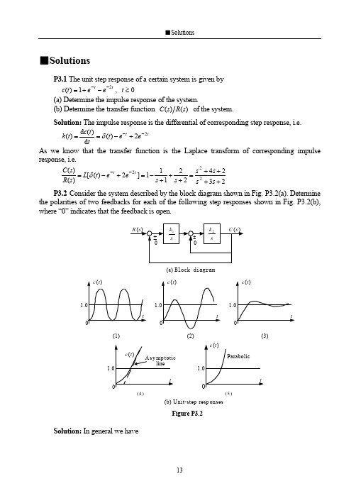
■SolutionsP3.1 The unit step response of a certain system is given by t t e e t c 21)(---+=, 0≥t (a) Determine the impulse response of the system.(b) Determine the transfer function )()(s R s C of the system.Solution:The impulse response is the differential of corresponding step response, i.e.t t e e t tt c t k 22)(d )(d )(--+-==δAs we know that the transfer function is the Laplace transform of corresponding impulse response, i.e.232422111]2)([)()(222++++=+++-=+-=--s s s s s s e e t L s R s C tt δP3.2Consider the system described by the block diagram shown in Fig. P3.2(a). Determinethe polarities of two feedbacks for each of the following step responses shown in Fig. P3.2(b), where “0” indicates that the feedback is open.Solution:In general we have(a) Block diagram.1.1.1.1.1(b) U nit-step resp onses(1)(2)(3)(4)(5)Figure P3.221020221)()(k k s k s k k s R s C ±±=Note that the characteristic polynomial is210202)(k k s k s s ±±=∆where the sign of s k 2is depended on the outer feedback and the sign of 21k k is depended on the inter feedback.Case (1).The response presents a sinusoidal. It means that the system has a pair of pure imaginary roots, i.e. the characteristic polynomial is in the form of 212)(k k s s +=∆. Obviously, the outlet feedback is “–”and the inner feedback is “0”.Case (2).The response presents a diverged oscillation.The system has a pair of complex conjugate roots with positive real parts, i.e. the characteristic polynomial is in the form of 2122)(k k s k s s +-=∆. Obviously, the outlet feedback is “+”and the inner feedback is “–”.Case (3).The response presents a converged oscillation. It means that the system has a pair of complex conjugate roots with negative real parts, i.e. the characteristic polynomial is in the form of 2122)(k k s k s s ++=∆. Obviously,both the outlet and inner feedbacks are “–”.Case (4).In fact this is a ramp response of a first-order system. Hence, the outlet feedback is “0”to produce a ramp signal and the inner feedback is “–”.Case (5).Considering that a parabolic function is the integral of a ramp function, both the outlet and inner feedbacks are “0”.P3.3Consider each of the following closed-loop transfer function. By considering the location of the poles on the complex plane, sketch the unit step response, explaining the results obtained.(a) 201220)(2++=s s s Φ,(b) 61166)(23+++=s s s s Φ(c) 224)(2++=s s s Φ,(d) )5)(52(5.12)(2+++=s s s s ΦSolution:(a) )10)(2(20201220)(2++=++=s s s s s ΦBy inspection, the characteristic roots are 2-, 10-. This is an overdamped second-order system. Therefore, considering that the closed-loop gain is 1=Φk , its unit step response can be sketched as shown.(b) )3)(2)(1(661166)(23+++=+++=s s s s s s s ΦBy inspection, the characteristic roots are 1-, 2-, 3-.Obviously, all three transient components are decayed exponential terms. Therefore, its unit step response, with a closed-loop gain 1=Φk , is sketched as shown..1.1(c) 1)1(4224)(22++=++=s s s s ΦThis is an underdamped second-order system, because its characteristic roots are j ±-1. Hence, transient component is a decayed sinusoid. Noting that the closed-loop gain is 2=Φk , the unit step response can be sketched as shown.(d) )5](21[(5.12)5)(52(5.12)(222++=+++=s s s s s s )+ΦBy inspection, the characteristic roots are 21j ±-, 5-. Since51.0-<<-, there is a pair of dominant poles,21j ±-, for this system. The unit step response, with a closed-loop gain 5.0=Φk , is sketched as shown.P3.4 The open-loop transfer function of a unity negative feedback system is)1(1)(+=s s s G Determine the rise time, peak time, percent overshoot and setting time (using a 5% setting criterion).Solution: Writing he closed-loop transfer function2222211)(nn n s s s s s ωςωωΦ++=++=we get 1=n ω, 5.0=ς. Since this is an underdamped second-order system with 5.0=ς, the system performance can be estimated as follows.Rising time .sec 42.25.0115.0arccos 1arccos 22≈-⋅-=--=πςωςπn r t Peak time .sec 62.35.011122≈-⋅=-=πςωπn p t Percent overshoot %3.16%100%100225.015.01≈⨯=⨯=--πςπςσe e p Setting time .sec 615.033=⨯=≈ns t ςω(using a 5% setting criterion)P3.5 A second-order system gives a unit step response shown in Fig. P3.5. Find the open-loop transfer function if the system is a unit negative-feedback system.Solution:By inspection we have%30%100113.1=⨯-=p σSolving the formula for calculating the overshoot,.1.1Figure P3.5.0.23.021==-ςπςσe p , we have 362.0ln ln 22≈+-=ppσπσςSince .sec 1=p t , solving the formula for calculating the peak time, 21ςωπ-=n p t , we getsec/7.33rad n =ωHence, the open-loop transfer function is)4.24(7.1135)2()(2+=+=s s s s s G n n ςωωP3.6A feedback system is shown in Fig. P3.6(a), and its unit step response curve is shown in Fig. P3.6(b). Determine the values of 1k , 2k ,and a .Solution:The transfer function between the input and output is given by2221)()(k as s k k s R s C ++=The system is stable and we have, from the response curve,21lim )(lim 122210==⋅++⋅=→∞→k sk as s k k s t c s t By inspection we have%9%10000.211.218.2=⨯-=p σSolving the formula for calculating the overshoot, 09.021==-ςπςσe p , we have608.0ln ln 22≈+-=ppσπσςSince .sec 8.0=p t , solving the formula for calculating the peak time, 21ςωπ-=n p t , we getsec/95.4rad n =ωThen, comparing the characteristic polynomial of the system with its standard form, we have.2.2(a)(b)Figure P3.622222n n s s k as s ωςω++=++5.2495.4222===n k ω02.695.4608.022=⨯⨯==n a ςωP3.7A unity negative feedback system has the open-loop transfer function)2()(k s s k s G +=(a) Determine the percent overshoot.(b) For what range of k the setting time less than 0.75 s (using a 5% setting criterion).Solution: (a)For the closed-loop transfer function we have222222)(nn n s s k s k s ks ωςωωΦ++=++=hence, by inspection,we getsec /rad k n =ω, 22=ςThe percent overshoot is%32.4%10021=⨯=-ςπςσe p (b) Since 9.022<=ς, letting.sec 75.025.033<⨯=≈kt ns ςω(using a 5% setting criterion)results in2275.06⎪⎪⎭⎫⎝⎛>k , i.e. 32>k P3.8For the servomechanism system shown in Fig. P3.8,determine the values of k and a that satisfy the following closed-loop system design requirements.(a) Maximum of 40% overshoot.(b) Peak time of 4s.Solution:For the closed-loop transfer function we have22222)(nn n s s k s k s ks ωςωωαΦ++=++=hence, by inspection, we getk n =2ω, αςωk n =2,and n n k ωςςωα22==Taking consideration of %40%10021=⨯=-ςπςσe p results in280.0=ς.In this case, to satisfy the requirement of peak time, 412=-=ςωπn p t , we haveFigure P3.8.sec /818.0rad n =ωHence, the values of k and a are determined as67.02==n k ω, 68.02==nωςαP3.9 The open-loop transfer function of a unity feedback system is)2()(+=s s k s G A step response is specified as:peak time s 1.1=p t , and percent overshoot %5=p σ.(a) Determine whether both specifications can be met simultaneously. (b) If the specifications cannot be met simultaneously, determine a compromise value for k so that the peak time and percent overshoot are relaxed the same percentage.Solution:Writing the closed-loop transfer function222222)(nn n s s k s s ks ωςωωΦ++=++=we get k n =ωand k 1=ς.(a) Assuming that the peak time is satisfiedsec1.1112=-=-=k t n p πςωπwe get 16.9=k . Then, we have 33.0=ςand%5%33%10021>=⨯=-ςπςσe p Obviously, these two specifications cannot be met simultaneously.(b) In order to reduce p σthe gain must be reduced. Choosing sec 2.221==p p t t results in04.31=k , 57.01=ς, %102%3.111=>=p p σσRechoosing sec 31.21.22==p p t t results in85.21=k , 59.01=ς, %10.51.2%0.101=<=p p σσLetting sec 255.205.23==p p t t results in941.23=k , 583.03=ς, %10.2505.2%5.103=≈=p p σσIn this way, a compromise value is obtained as941.2=k P3.10A control system is represented by the transfer function)13.04.0)(56.2(33.0)()(2+++=s s s s R s C Estimate the peak time, percent overshoot, and setting time (%5=∆), using the dominant pole method, if it is possible.Solution:Rewriting the transfer function as]3.0)2.0)[(56.2(33.0)()(22+++=s s s R s C we get the poles of the system: 3.02.021j s ±-=,, 56.23-=s . Then, 21,s can be considered as a pair of dominant poles, because )Re()Re(321s s <<,.Method 1. After reducing to a second-order system,the transfer function becomes13.04.013.0)()(2++=s s s R s C (Note: 1)()(lim 0==→s R s C k s Φ)which results in sec /36.0rad n =ωand 55.0=ς. The specifications can be determined assec 0.42112ςωπ-=n p t , %6.12%10021=⨯=-ςπςσe p sec 67.2011ln 12=⎪⎪⎪⎭⎫⎝⎛-=ς∆ςωn s t Method 2. Taking consideration of the effect of non-dominant pole on the transient components cause by the dominant poles, we havesec0.8411)(231=--∠-=ςωπn p s s t %6.13%10021313=⨯-=-ςπςσe s s s p sec 6.232ln 1313=⎪⎪⎭⎫⎝⎛-⋅=s s s t n s ∆ςωP3.11By means of the algebraic criteria, determine the stability of systems that have thefollowing characteristic equations.(a) 02092023=+++s s s (b) 025103234=++++s s s s (c) 021*******=+++++s s s s s Solution:(a) 02092023=+++s s s . All coefficients of the characteristic equation are positive. Using L-C criterion,1609120202>==D This system is stable.(b) 025103234=++++s s s s . All coefficients of the characteristic equation are positive. Using L-C criterion,15311002531103<-==D This system is unstable.(c) 021*******=+++++s s s s s . (It’s better to use Routh criterion for a higher-order system.)All coefficients of the characteristicequation are positive. Establish the Routh arrayas shown.There are two changes of sign in the first column, this system is unstable.P3.12The characteristic equations for certain systems are given below. In each case,determine the number of characteristic roots in the right-half s -plane and the number of pure imaginary roots.(a) 0233=+-s s (b) 0160161023=+++s s s (c) 04832241232345=+++++s s s s s (d) 0846322345=--+++s s s s s Solution:(a) 0233=+-s s . The Routh array shows that there are two changes of sign in the first column. So that there are two characteristic roots in the right-half s -plane.(b) 0160161023=+++s s s The 1s -row is an all-zero one and an auxiliary equation is made based on 2s -row162=+s Taking derivative with respect to s yields2=s The coefficient of this new equation is inserted in the1s row, and the Routh array is then completed. By inspection, there are no changes of sign in the firstcolumn, and the system has no characteristic roots in the right-half s -plane. The solution of the auxiliary are 4j s ±=, the system has a pair of pure imaginary roots.(c) 04832241232345=+++++s s s s s . The Routh array is established as follows.The 1s -row is an all-zero one and an auxiliary equation based on 2s -row is42=+s Taking derivative with respect to s yields2=s The coefficient of this new equation isinserted in the 1s row, and the Routh array is then completed. By inspection, there are no changes of sign in the first column, and the system has no characteristic roots in the right-half5s 1914s 21023s 402s 1021s -0.800s 23s 1-32s 0 0>⇒ε21s εε23--0s 23s 1162s 101⇒16016⇒1s 02⇒0s 165s 112324s 31⇒248⇒4861⇒3s 41⇒164⇒2s 41⇒164⇒1s 02⇒0s 4s -plane. The solution of the auxiliary are 2j s ±=, the system has a pair of pure imaginaryroots.(d) 0846322345=--+++s s s s s .The Routh array is established as follows.The 3s -row is an all-zero one and an auxiliary equationbased on 4s -row is04324=-+s s Taking derivative with respect to s yields643=+s s The coefficient of this new equation is inserted in the 3s row, and the Routh array is then completed. By inspection, the sign inthe first column is changed one time, and the system has one root in the right-half s -plane. The solution of the auxiliary are 121±=,s 243j s ±=,, the system has one pair of pure imaginary roots.P3.13The characteristic equations for certain systems are given below. In each case, determine the value of k so that the corresponding system is stable. It is assumed that k is positive number.(a) 02102234=++++k s s s s (b) 0504)5.0(23=++++ks s k s Solution: (a) 02102234=++++k s s s s .The system is stable if and only if⎪⎪⎩⎪⎪⎨⎧<⇒>=>9022*********k k D k i.e. the system is stable when 90<<k .(b) 0504)5.0(23=++++ks s k s . The system is stable if and only if⎪⎩⎪⎨⎧>-+⇒>-+⇒>+=>>+0)3.3)(8.34(05024041505.00,05.022k k k k k k D k k i.e. the system is stable when 3.3>k .P3.14The open-loop transfer function of a negative feedback system is given by)12.001.0()(2++=s s s Ks G ςDetermine the range of K and ςin which the closed-loop system is stable.Solution: The characteristic equation is2.001.023=+++K s s s ςThe system is stable if and only if5s 13-44s 21⇒63⇒-84-⇒3s 04⇒06⇒02s 3-8 1s 5000s -8⎪⎩⎪⎨⎧<⇒>-⇒>=>>ςςς200010200101.02.002.0,02K K .ς.K D k The required range is 020>>K ς.P3.15The open-loop transfer function of negative feedback system is given)12)(1()1()()(+++=s Ts s s K s H s G The parameters K and T may be represented in a plane with K as the horizontal axis and T as the vertical axis. Determine the region in which the closed-loop system is stable.Solution:The characteristic equation is)1()2(223=+++++K s K s T Ts Since all coefficients are positive, the system is stable if and only if)1)(2(01222>++⇒>++=K T K T KT D 022>++-T KT K 04)2()2(>+-+-T T K 4)1)(2(<--⇒K T The system is stable in the region 4)1)(2(<--K T , which is plotted as shown. (Letting 2-='T T and 1-='K K results in 4<''K T .)P3.16A unity negative feedback system has an open-loop transfer function)1)(1)(1()(2+++=Ts n nTs Ts Ks G where 10≤≤n , 0>K , T is a positive constant.(a) Determine the range of K and n so that the system is stable.(b) Determine the value of K required for stability for 1=n , 0.5, 0.1, 0.01, and 0.(c) Discuss the stability of the closed-loop system as a function of n for a constant K .Solution:The closed-loop characteristic equation is)1)(1)(1(2=+++K Ts n nTs Ts +i.e. 01)1()(22223333=+++++++K Ts n n s T n n n s T n +(a) The system is stable if and only if)1(1)1(233222>+++++=Tn n Tn K T n n n D i.e.)1(0)1()1(2223322>--++⇒>+-++K n n n n T K T n n n ⎪⎪⎭⎫⎝⎛-++⎪⎪⎭⎫ ⎝⎛+++<⇒-⎪⎪⎭⎫⎝⎛++<1111112222n n n n n n K n n n K ⎪⎭⎫ ⎝⎛++<⇒⎪⎪⎭⎫⎝⎛-+++++<2222211)1(11)1(n n K n n n n n n n K '21hence, the system is stable when ⎪⎭⎫ ⎝⎛++<<2211)1(0n n K .(b) The value of K required for stability for 1=n , 0.5, 0.1, 0.01, and 0are calculated as shown.80<<K for 1=n ,5.110<<K for 5.0=n ,21.1220<<K for 1.0=n ,102020<<K for 01.0=n ,∞<<K 0for 0=n .(c) For a constant K , the stability of the closed-loop system is related to the value of n , the larger the value of n ,the easier the system to be stable. (Stagger principle.)P3.17A unity negative feedback system has an open-loop transfer function)16)(13()(++=s s s Ks G Determine the range of k required so that there are no closed-loop poles to the right of the line 1-=s .Solution:The closed-loop characteristic equation is18)6)(3(0)16)(13(=+++⇒=+++K s s s K ss s i.e. 01818923=+++K s s s Letting 1~-=s s resulting in)1018(~3~6~018)5~)(2~)(1~(23=-+++⇒=+++-K s s s K s s s Using Lienard-Chipart criterion, all closed-loop poles locate in the right-half s ~-plane, i.e. to the right of the line 1-=s , if and only if⎪⎩⎪⎨⎧<⇒>-⇒>-=>⇒>-91408.1820311018695,010182K K K D K K The required range is 91495<<K , or 56.10.56<<K P3.18A system has the characteristic equation291023=+++k s s s Determine the value of k so that the real part of complex roots is 2-, using the algebraiccriterion.Solution:Substituting 2~-=s s into the characteristic equation yields02~292~102~23=+-+-+-k s s s )()()(0)26(~~4~23=-+++k s s s The Routh array is established as shown.If there is a pair of complex roots with real part of 2-, then26=-k 3s 112s 426-k 1s 0si.e. 30=k . In the case of 30=k , we have the solution of the auxiliary equation j s ±=~, i.e. j s ±-=2.P3.19 An automatically guided vehicle is represented by the system in Fig. P3.19.(a) Determine the value of τrequired forstability.(b) Determine the value of τwhen one root of the characteristic equation is 5-=s , and the values of the remainingroots for the selected τ.(c) Find theresponse of the system to a step command for the τselected in (b).Solution:The closed-loop transfer function is10101010)()()(23+++==s s s s R s C s τΦ(a) The closed-loop characteristic equation is 010101023=+++s s s τSince all coefficients are positive, the system is stable if and only if1.0010110102>⇒>=ττD (b) Substituting 5~-=s s into the characteristic equation yields0105~105~105~23=+-+-+-)()()(s s s τ0)50135(~)2510(~5~23=-+-+-ττs s s In the case of 050135=-τ, i.e. 7.2=τ, we have 0~1=s , i.e. 51-=s . Solving the characteristic equation with 7.2=τ, i.e. 0~2~5~23=++-s s s results in 56.4~2=s and 44.0~3=s . Hence the remaining roots are 44.02-=s and 56.43-=s .(c) The closed-loop transfer function for 7.2=τis)5)(56.4)(44.0(10)(+++=s s s s ΦThe unit step response of the system is500.156.421.144.021.111)5)(56.4)(44.0(10)(+--+++-=⋅+++=s s s s s s s s s C tt t e e e t c 556.444.000.121.121.11)(----+-=Or, considering that there is a dominant pole for the system, we have127.2144.044.0)(+=+≈s s s Φte t c 44.01)(--≈P3.20A thermometer is described by the transfer function )11+Ts . It is known that, measuring the water temperature in a container, one minute is required to indicate 98% of the actual water temperature. Evaluate the steady-state indicating error of the thermometer if the container is heated and the water temperature is lineally increased at the rate of C/min 10 .travelFig.P3.19Solution:One minute required to indicate 98% of the actual water temperature means that the setting time is sec 604=≈T t s , i.e. the time constant of the thermometer issec15≈T The indicated error caused by the given ramp input, C/sec)(6010C/min)(10)( ==t t r , is222611611161)()()(sTs Ts s Ts s s C s R s E ⋅+=⋅+-=-=By inspection, a first-order system is always stable. Hence, the steady-state indicating error isC ss s s e s ss 5.26111515lim 20=⋅+⋅=→P3.21 Determine the steady-state error for a unit step input, a unit ramp input, and an acceleration input 22t for the following unit negative feedback systems. The open-loop transfer functions are given by(a) )12)(11.0(50)(++=s s s G ,(b) )5.0)(4(10)()(++=s s s s H s G (c) )11.0()15.0(8)(2++=s s s s G ,(d) )5)(1(10)(2++=s s s s G (e) )2004()(2++=s s s k s G Solution:(a) )12)(11.0(50)(++=s s s G . This is a second-order system and must be stable. Asa 0-type system,0=υ, the corresponding error constants are50=p K , 0=v K , 0=a K Consequently, the corresponding steady-state errors are0196.0501110.=+=+=p r ss K r ε, ∞==v v ss K v 0.ε, ∞==aa a ss K v .εrespectively.(b) )5.0)(4(10)()(++=s s s s H s G . The characteristic polynomial is40209)(23+++=s s s s τ∆Using L-C criterion,01402014092>==D the closed-loop system is stable. By inspection, system type 1=υand open-loop gain 5=K . Hence, the corresponding steady-state errors are0.=r ss ε, 2.01.==Kv ss ε, ∞=a ss .εrespectively.(c) )11.0()15.0(8)(2++=s s s s G . The characteristic polynomial is40209)(23+++=s s s s τ∆Using L-C criterion01402014092>==D the closed-loop system is stable. By inspection, system type 1=υand open-loop gain 5=K . Hence, the corresponding steady-state errors are0.=r ss ε, 2.01.==Kv ss ε, ∞=a ss .εrespectively.(d) )5)(1(10)(2++=s s s s G . The characteristic polynomial is1056)(234+++=s s s s ∆By inspection, this system is unstable (due to constructional instability).(e) )2004()(2++=s s s k s G . The characteristic polynomial isks s s s +++=2004)(23∆Using L-C criterionkkD -==800200142the closed-loop system is stable if and only if 8000<<k . This is a 1-type system with a open-loop gain 200k K =. In the case of 8000<<k , i.e. 40<<K ,the corresponding steady-state errors are0.=r ss ε, kK v ss 2001.==ε, ∞=a ss .εrespectively.P3.22 The open-loop transfer function of a unity negative feedback system is given by)1)(1()(21++=s T s T s Ks G Determine the values of K , 1T , and 2T so that the steady-state error for the input, bt a t r +=)(, is less than 0ε. It is assumed that K , 1T , and 2T are positive, a and b are constants.Solution:The characteristic polynomial is Ks s T T s T T s ++++=221321)()(∆Using L-C criterion, the system is stable if and only if2121212121212001T T T T K T KT T T T T K T T D +<⇒>-+⇒>+=Considering that this is a 1-type system with a open-loop gain K , in the case of 2121T T T T K +<, we have0..εεεεεbK Kbv ss r ss ss >⇒<=+=Hence, the required range for K is21210T T T T K b+<<εP3.23 The open-loop transfer function of a unity negative system is given by)1()(+=Ts s K s G Determine the values of K and T so that the following specifications are satisfied:(a) The steady-state error for the unit ramp input is less than 02.0.(b) The percent overshoot is less than %30and the setting time is less s 3.0.Solution:Assuming that both K and T are positive, the system must be stable. To meet the requirement on steady-state error, we have5002.010≥⇒≤==k KK v v ss εTo meet the second requirement, we have358.0%3021≥⇒≤=-ςσςπςe p and%)2(,10sec3.03=≥⇒≤≈∆ςωςωn ns t Considering that KT21=ςand TKn =ω, we get 95.1358.021≤⇒≥=KT KTς05.02010≤⇒=≥=T KT T K n ςωFinally, to met all specifications, the required ranges K and T are⎪⎩⎪⎨⎧≤≤≤T K T 95.15005.0P3.24 The block diagram of a control system is shown in Fig. P3.24, where)()()(s C s R s E -=. Select the values of τand b so that the steady-state error for a ramp input is zero.Figure P3.24Solution:Assuming that all parameters are positive, the system must be stable. Then, the error response is)()1)(1()(1)()()(21s R K s T s T b s K s C s R s E ⎥⎦⎤⎢⎣⎡++++-=-=τ)()1)(1()1()(2121221s R Ks T s T Kb s K T T s T T ⋅+++-+-++=τLetting the steady-state error for a ramp input to be zero, we get221212210.)1)(1()1()(lim )(lim sv Ks T s T Kb s K T T s T T s s sE s s r ss ⋅+++-+-++⋅==→→τεwhich results in⎩⎨⎧=-+=-00121τK T T Kb I.e. K T T 21+=τ, Kb 1=.P3.25 The block diagram of a compound system is shown in Fig. P3.25.Select the values ofa andb so that the steady-state error for a parabolic input is zero.Solution: The characteristic polynomial is 1012.0002.0)(23+++=s s s s ∆Using L-C criterion,1.01002.01012.02>==D the system is stable. The transfer function between error and input is given by10)102.0)(11.0()(10)102.0)(11.0()102.0)(11.0(101)102.0)(11.0()(101)()()(22++++-++=++++++-=-=s s s bs as s s s s s s s s s bs as s C s R s E 10)102.0)(11.0()101()101.0(002.023+++-+-+=s s s s b s a s Letting the steady-state error for a parabolic input to be zero yields010)102.0)(11.0()101()101.0(002.0lim 30230.=⋅+++-+-+⋅=→sa s s s sb s a s s s ass εwhich results inFigure P3.25⎩⎨⎧=-=-01012.00101a b i.e. 012.0=a , 1.0=b .P3.26 The block diagram of a system is shown in Fig. P3.26. In each case, determine the steady-state error for a unit step disturbance and a unit ramp disturbance, respectively.(a) 11)(K s G =, )1()(222+=s T s K s G (b) ss T K s G )1()(111+=, )1()(222+=s T s K s G , 21T T >Solution: (a) In this case the system is of second-order and must be stable. The transferfunction from disturbance to error is given by212212.)1(1)(K K Ts s K G G G s d e ++-=+-=ΦThe corresponding steady-state errors are12120.11)1(lim K s K K Ts s K s s p ss -=⋅++-⋅=→ε∞→⋅++-⋅=→22120.1)1(lim sK K Ts s K s s a ss ε(b) Now, the transfer function from disturbance to error is given by)1()1()(121222.+++-=s T K K s T s sK s d e Φand the characteristic polynomial is21121232)(K K s T K K s s T s +++=∆Using L-C criterion,)(121211212212>-==T T K K T K K T K K D the system is stable. The corresponding steady-state errors are01)1()1(lim 1212220.=⋅+++-⋅=→s s T K K s T s sK s s p ss ε121212220.11)1()1(lim K s s T K K s T s sK s s a ss -=⋅+++-⋅=→εFigure P3.26P3.27 The block diagram of a compound system is shown in Fig. P3.26, where1)(111+=s T K s G , )1()(222+=s T s K s G ,233)(K K s G =Determine the feedforward block transfer function )(s G d so that the steady-state error due tounit step disturbance is zero.Solution: the characteristic equation is 0121=+G G , i.e.21221321)(K K s s T T s T T ++++Using L-C criterion, the system is stable if and only if002121212121212>-+=+=T T K K T T T T K K T T D hence, the system is stable if212121T T T T K K +<The transfer function from disturbance to error is given by111)(1)1(1)(2211112322212123.+⋅++⎥⎦⎤⎢⎣⎡⋅+++-=+--=s T K s T K s G s T K K K s T s K G G G G G G G s dd de Φ21212113)1)(1()()1(K K s T s T s s G K K s T K d +++++-=When the system is stable, letting the steady-state error to be zero yields0)1)(1()()1(lim 0212121130=⋅⎥⎦⎤⎢⎣⎡+++++-⋅=→s d K K s T s T s s G K K s T K s d s ss ε[]0)()1(lim 21130=++→s G K K s T K d s i.e.213)(K K K s G d -=The feedforward block function is 213)(K K K s G d -=, where 212121T T TT K K +<.Figure P3.27。
自动控制原理_英文论文

Automatic Control Applications In the social life班级:学号::Programmable controller to control watersupply systemConstant pressure water supply system for a certain industry or a particular user is very important, for example in certain production processes, if the tap water supply or short-time shortages due to insufficient water, which may affect product quality, serious product scrap and damage to the equipment. When a fire occurs, if the water pressure is insufficient or no water supply, no rapid fire, can lead to significant economic losses and casualties. So some of the water area with constant voltage water supply system, has great economic and social significance.Mechanical technologyOld pressurized equipment, General starts or stops usingconstant-pressure water supply pressurizing station exit of pumps and regulating valve opening is to be achieved. Control system is the use of relay-contactor control circuits, this line complex, difficult to maintain, and operate trouble, workers to guards on duty 24 hours, labor intensive. It is necessary to reform, improve the level of automation.Electrical technologyPresented to a tap water pressure station quick starting of constant pressure water supply control system, the FP3 produced by Matsushita programmable logic controller (PLC) controls with Advantech industrial computer monitor, high degree of automation, the whole program to work automatically, clearly shows the real-time status of each device, and automatically adjust the water pressure. The system also has a wide range of protection, such as water pressure alarm fault alarm, water alarm, valves, pump motor current flow and processing alarm processing and so on.System structure and control requirements of mechanical and electrical engineering technology network,Constant pressure water supply system consists of the main loop, the alternate loop of water supply,Composed of 2 water tank and pump house, as shown in Figure 1.Pumping station equipped with a 1# ~ 6# a total of 6 sets of150kW pumps. There is more than one (V1 ~ V23) electric valvecontrols the water circuit and the flow of water.Requires the constant pressure water-supply system has the following basic operating functions.Electrical technical machinery technolog.When municipal water pressure is higher than the setting pressure 21.56x10⁴Pa, directly by the municipal water supply in electrical technology. When city water is lower than the set pressure, but under the pressure of not less than 7.84x10⁴Pa when using direct pumping pressurized water supply solutions. Of progressively starting 2 pumps to pipe network pressure. When city water higher than the set pressure is detected, then converted to city water supply directly. When the tap water pressure is lower than 2.94x10⁴Pa, or when there is a negative pressure signal exactly, should immediately convert water pressure, but should ensure that the pool water level above the minimum water level conditions. Mechanical technology.When pumping or pumping water pressure water supply is used, should be able to automatically adjust the water pressure for a given value of its total exports, control deviation is less than or equal to 10%. Electrical technologyCAD/CAM technologyDesign of PLC control system CAD/CAM technologyConstant pressure water supply system for detection and control of more is a large control system. According to its characteristics, we have chosen Panasonic FP3 programmable controller is a controller.The controller with it can programming sequence controller comparedto, has some obviously of advantages, as FP3 used has module ofdesign, can according to actual needs flexible assembled, usingconvenient, I/O distribution used free programming way; capacity big, program volume only by scan cycle limit, and scan cycle can in mustrange within itself change; has A/D, and D/A, and pulse output, andlocation control, senior unit, can achieved "shared memory"; additionalso some special of function. Mechanical technologyConstant pressure water supply system of PLC system structure isshown in Figure 1-dashed border. Industrial computer to monitor theentire system, the display shows the total pressurized systemstructure, read the real-time status of each valve and pump, waterpressure and flow rate, the valve opening, the pool water level andother parameters, and real-time display alarm and fault record.Electrical technologyBoth analog input and switch input. Analog by a/d module input,total 27 channels. There are 96 I/O points.CAD/CAM technologyMechanical technologyPLC software designElectrical technologyAccording to constant pressure water supply system operational requirements, PLC control system to monitor City tap water, and waterhas to decide whether to start the water pump, or direct waterpumping programme or by pumping pressurized water full solution. Control system the procedure is more complex. Electrical/mechanical engineering technology networkIn the control process, water supply and pressure regulation isan important and one of the more distinctive design, focusing onsoftware design of automatic constant-pressure function.Due to the large water system piping length and diameter, the opening and closing of the valve, pipe network pressure is slow, so the system is a system with large time delay. And because it is based on the old equipment transformation, to make use of existing equipment, it does not use speed regulator, instead of using the various methods to adjust the water pressure. First used segment regulation method, put hydraulic deviation is divided into four segment, that 10%, and 20%, and 30%, and 40%, dang detection to deviation smaller Shi, output of control volume (butterfly valve of incremental) smaller, and operation cycle also larger; In addition, when the deviation is less than or equal to ± 10%, coupled with the fuzzy control, according to d EK=EK-EK-1 to determine whether regulating butterfly valve opening, to further reduce the errors to ensure its error less than or equal to ± 10% requirements. Pressure is regula ted by multiple methods combination of outlet pressure can be satisfied with the effect. Electrical technical machinery technologyConclusionThe design of constant pressure water supply control system with PLC have successfully applied to an industrial zone, results showed that the system satisfies its design requirements, with convenient operation, high reliability, data integrity and monitor timely advantage and significantly reduce the labor intensity of workers, shorten the operating time, operators, maintainers, managers at home. The successful design of the monitoring system, as well as similar systems of old equipment modification to provide a good experience.。
现代控制理论浙大
三、现代控制理论与古典控制理论的对比
• 共同 对象-系统 主要内容 分析:研究系统的原理和性能 设计:改变系统的可能性(综合性能)
用 • 区别
古典
研究对象:单入单出(SIS0)系统,线性定常 工具:传递函数(结构图),已有初始条件为零时才适
试探法解决问题 : PID串联、超前、滞后、反馈
整理得一阶微分方程组为
Ri (t )
L
di(t) dt
uc
u(t)
duc(t) 1 i(t) dt C
i(t) C duc dt
di(t) dt
1 L
uc
(t)
R L
i(t)
1 L
u(t)
即
x1 (t )
1 C
x2 (t)
状态方程
x2
(t)
1 L
x1 (t )
R L
x2
(t)
1 L
u(t)
状态空间 表达式
研究对象:多入多出(MIMO)系统、
线性定常、非线性、时变、
第9页/共66页
现代控制理论预览
可控性 可观性 稳定性
建模 分析 设计
状态空间 表达式
建立 求解 转换
状态反馈 状态观测器 最优控制
第10页/共66页
第一章 控制系统的状态空间表达式
主要内容: • 状态变量及状态空间表达式 • 状态变量及状态空间表达式的系统结构图 • 状态变量及状态空间表达式的建立 • 状态矢量的线性变换 • 从状态空间表达式求传递函数阵
(1) 专家系统;(2)模糊控制,人工智能 (3) 神经网络,人脑模型;(4)遗传算法 控制理论与计算机技术相结合→计算机控制技术
第7页/共66页
浙江大学845自动控制原理考研真题试卷

紧急通知本资料由浙江大学控制科学与工程学院16届专业课129分学长,也就是我本人亲自整理编排而成。
大家可以叫我学长,年龄比我大的辞职考的可以叫我小弟。
资料不同于市面上那些看起来非常诱人实则是粗制烂造的资料,而是以一个考过845自控的过来人的经验,完全从学生的体验出发,做到资料最全,资料最好,资料最精致。
全套资料包括葵花宝典一到葵花宝典九共九本资料,每本资料都是我精心编辑整理的,并做了精美的封面,一共650页完美打印发给大家,大家把这650从头到尾肯透了,再做下我推荐的几本资料书(16年有一道15分的大题就是上面的类似题,第三问很多高手都没做出来,注意不是周春晖那本哈),可以说完全没问题了。
这是其它卖家不可能做到的。
同时赠送845自控全套电子资料。
葵花宝典一完全由我本人原创,里面包含了考浙大845自动控制原理的全部问题,比如考多少分比较保险,怎么复习,有哪些好的资料书,最近几年考题变化及应对策略,浙大常考题型,招生名额,复试资料,导师联系,公共课复习用书及方法以及845近年命题风格分析等一系列问题,全是我的心得和经验,方法,技巧等,说句心里话,我自己都觉得这些资料非常宝贵,能帮助学弟学妹们少走很多弯路。
注意:前面是一些关于我的故事,有些地方可能对你有用,如果不感兴趣,可以直接拉到后面去看,资料清单和图片都在后面。
学长自我介绍学长姓邓,名某某,男,本科于14年毕业于四川大学电气信息学院自动化专业,考浙大控制考了3次,14年大三时第一次考浙大控制总分没过线。
当时我们学校有三个同学征战浙大控制科学与工程,结果全军覆没,只有我一人过了300分,由此可见考浙大控制还是很有难度的,其中一个难点就是专业课的信息和专业课的命题走向的获取,当时我们都不是很清楚,蒙着头自己学,去图书馆借了很多自动控制原理的资料书来看,我自我感觉学得还不错,当时我一个同学考电子科大的自动化,经常跑来问我自控的问题,我基本都能给他解答出来,他说我好牛逼,觉对没有问题,然而最后的结果是他考电子科大自动控制原理137,而我只考了96分。
自动化专业英语作业英文。

Closed-loop Control of DC Drivers直流驱动的闭环控制A basic scheme of the closed-loop speed control system employing current limit control, also known as parallel current control, is shown in Fig. 1-5B-1. ω* sets the speed reference. A signal proportional to the motor speed is obtained from the speed sensor. The speed sensor output is filtered to remove the AC ripple and compared with the speed reference.The speed error is processed through a speed controller. The output of the speed controller u c adjusts the rectifier firing angleαto make the actual speed close to the reference speed. The speed controller is usually a PI (proportional and integral) controller and serves three purposes—stabilizes the drive and adjusts the damping ratio at the desired value, makes the steady-state speed-error close to zero by integral action, and filters out noise again due to the integral action. The drive employs current limit control, the purpose of which is to prevent the current from exceeding safe values. As long as IA<Ix, where, Ix is the maximum permission value of IA, the current control loop does not affect the drive operation. If IA exceeds Ix, even by a small amount, a large output signal is produced by the threshold circuit, the current control, and the speed error iscorrected essential at a constant current equal to the maximum permission value.When the speed reaches close to the desired value, IA falls below IX, the current control goes out of action and speed controlled takes over. Thus in this scheme, at any given time the operation of the drive is mainly controlled either by the speed control loop or the current control loop, and hence it is also called parallel current control.Another scheme of closed-loop speed control is shown in Fig.1-5B-2. It employs an inner current control loop within an outer speed loop. The output of the current controller uc adjusts the converter firing angle such that the actual speed is brought to a value set by the speed commendωm*.Any positive speed error, cause by either an increase in the load torque, produces a higher current reference I a*. The motor accelerates due to an increase in I a, to correct the speed error and finally settles at a new I a* which makes the motor torque equal to the load torque and the speed error closed to zero.For any large positive speed error, the current limiter saturates and the current reference I a* is limited to a value I am*, and the drive current is not allowed to exceed the maximum permission value. The speed error is corrected at the maximum permissible armaturecurrent until the speed error becomes small and the current limiter comes out of saturation. Now the speed error is corrected with IA less than the permissible value.A negative speed error will set the current reference IA at a negative value. Since the motor current cannot reverse, a negative IA is of no use. It will however “charge” the PI controller. When the speed error becomes positive the “charged” PI controller will take a longer time to respond, causing unnecessary delay in the control action. The current limiter is therefore arranged to set a zero-current reference for negative speed errors.Since the speed control loop and the current control loop are in cascade, the inner current control is also known as cascade control. It is also called current guided control. It is more commonly used than the current-limit control because of the following advantages: 1.It provides faster response to any supply voltage disturbance.This can be explain by considering the response of two drives toa decrease in the supply voltage. A decrease in the supplyvoltage reduces the motor current and torque. In the current-limit control, the speed falls because the motor torque is less than the load torque that has not changed. The resulting speed error is brought to the original value by setting the rectifier firing angle at a lower value. In the case of inner currentcontrol, the decrease in motor current, due to the decrease in the supply voltage, produces a current error which changes the rectifier firing angle to bring the armature current back to the original value. The transient response is now governed by the electrical time constant of the motor. Since the electrical time constant of a drive is much smaller compared to the mechanical time constant, the inner current control provides a faster response to the supply voltage disturbance.2.For certain firing schemes, the rectifier and the control circuittogether have a constant gain under continuous of 5 percent.Under discontinuous conduction, the gain reduces. The higher the reduction is in the conduction angel, the greater the reduction is in the gain. The drive response becomes sluggish in discontinuous conduction and progressively deteriorates as the conduction angle reduces. If an attempt is made to design the drive for discontinuous conduction current control loop providesa closed loop around the rectifier and the control circuit, andtransient response of the drive with the inner current loop is superior to that with the current-limit control.3.In the current-limit control, the current must first exceed thepermissible value before the current-limit action can be initiated.Since the firing angle can be changed only at discrete intervals,substantial current overshoot can occur before the current limiting becomes effective.Small motors are more tolerant to high transient current. Therefore, to obtain a fast transient response is then needed only for abnormal values of current. In such cases because of the simplicity, current-limit control is employed.Both the schemes have different responses for the increase and decrease in the speed command. A decrease in speed command at the most can make the motor torque zero; it cannot be reversed as braking is not possible. The drive decelerates mainly due to the load torque. When load torque is low, the response to a decrease in the speed command will be slow. These drives are therefore suitable for application with large load torque, such as paper and printing machines, pumps, and blowers.。
自动控制原理中英文对照

自动控制原理中英文对照Automatic Control Principles 自动控制原理Introduction 简介Automatic control principles refer to the principles and theories that govern the design, development, and implementation of automated control systems. These systems are used in a variety of fields, including manufacturing, transportation, aerospace, and more. The goal of automatic control principles is to create systems that can operate independently and make decisions based on the input they receive.自动控制原理是指掌握设计、开发和实现自动控制系统的原理和理论。
这些系统应用于各种领域,包括制造业、交通运输、航空航天等。
自动控制原理的目标是创建能够独立运作并根据所接收的输入做出决策的系统。
Types of Control Systems 控制系统的类型There are two main types of control systems: open-loop and closed-loop. Open-loop systems are those that operate without any feedback, meaningthat they do not adjust their output based on the input they receive. Closed-loop systems, on the other hand, use feedback to adjust their output based on the input they receive.控制系统主要有两种类型:开环和闭环。
自动化专业英语部分课文与翻译
An electrical circuit or network is composed of elements such as resistors , inductors , and capacitors connected together in some manner .If the network contains no energysources , such asbatteries or electrical generators,it is known as a passive network.On the other hand, if one or more energy sources are present , the resultant combination is an active network. In studying the behavior of an electrical network,we are interested in determining the voltages and currents that exist within the circuit. Since a network is composed of passive circuit elements,we must first define the electrical characteristics of these elements.电路或电网络由以某种方式连接的电阻器、电感器和电容器等元件组成。
如果网络不包含能源,如电池或发电机,那么就被称作无源网络。
换句话说,如果存在一个或多个能源,那么组合的结果为有源网络。
在研究电网络的特性时,我们感兴趣的是确定电路中的电压和电流。
因为网络由无源电路元件组成,所以必须首先定义这些元件的电特性.In the case of a resistor, the voltage-current relationship is given by Ohm's law, which ststes that the voltage across the resistor is equal to the current through the resistor multiplied by the value of the resistance. Mathematically, this is expressed as u=iR where u=voltage , V; i=current, A; R=resistance Ω.就电阻来说,电压-电流的关系由欧姆定律给出,欧姆定律指出:电阻两端的电压等于电阻上流过的电流乘以电阻值。
浙江大学学生手册考题

浙江大学学生手册考题浙江大学学生手册考试的目的是考核学生对学生手册的掌握情况,下面是店铺精心为你们整理的浙江大学学生手册考题的相关内容,希望你们会喜欢!浙江大学学生手册考题一、判断题(每题1分,25分):1. 学生可在未报名注册情况下修读辅修专业、双专业/双学位的有关课程,并在完成相应课程之后申请辅修专业、双专业/双学位的学业证书。
()2. 与我校签订了校际、院(系)际合作交流协议的学校修得的课程可以申请转换为我校的课程。
()3. 学生的成绩单上记载原始的学分、成绩,系统内部将按照转换后的学分、成绩计算学分及绩点。
()4. 各专业主修专业确认的选拔的标准是全校统一的。
()5. 有个学生大一上学期获得25学分,大一下学期获得30学分,但大二上学期只获得了7学分,此学生在大二上学期应该被退学警告。
()6. 学校对学生的处分应坚持公平、公开、公正原则,坚持教育与处分相结合原则,坚持学生申诉权受保障原则。
()7. 受处分者不得申请国家助学贷款,但本学年内可以评定奖学金及各种荣誉称号。
()8. 处分决定应有选择地归入学校文书档案和本人档案。
()9. 动手打人未伤他人的给予警告处分。
()10. 违章用电、用火、用危险品及其他危害公共安全行为的,给予警告以上、记过以下处分;()11. 尚未完全丧失辨认或者控制自己行为能力的时候实施违纪行为的,可以减轻处分或者不处分。
()12. 盗用他人名义冒领他人钱物的,除返还冒领的钱物外,给予记过或者留校察看处分。
()13. 在进行科学研究中,存在学术不端行为,情节较轻者,给予严重警告或记过处分;情节严重者,给予开除学籍处分。
()14. 处分决定作出后,学校采取适当方式在校内予以公布。
处分决定无法送达时,学校采用公告方式送达。
()15. 奖学金每学年评定一次,在每年的9-10月结合学生学年综合评价进行。
()16. 外设奖学金原则上在获得优秀学生奖学金和单项奖学金的学生中评定。
自动控制原理 英文版

y
y 0 y
y0
df dx
x0
f ( x)
y k x
A
x
x 0 x0 x
Example 2.5 : Elasticity equation
F ( x ) kx
suppose : k 12.65; 1.1;
F ( x ) kx
'
operating point x0 0.25
1) Identify the output and input variables of the control systems.
2) Write the differential equations of each system’s component in terms of the physical laws of the components. * necessary assumption and neglect. * proper approximation. 3) Dispel the intermediate(across) variables to get the input-output description which only contains the output and input variables. 4) Formalize the input-output equation to be the “standard” form: Input variable —— on the right of the input-output equation . Output variable —— on the left of the input-output equation. Writing the equation—according to the falling-power order.
- 1、下载文档前请自行甄别文档内容的完整性,平台不提供额外的编辑、内容补充、找答案等附加服务。
- 2、"仅部分预览"的文档,不可在线预览部分如存在完整性等问题,可反馈申请退款(可完整预览的文档不适用该条件!)。
- 3、如文档侵犯您的权益,请联系客服反馈,我们会尽快为您处理(人工客服工作时间:9:00-18:30)。
Homework Week7
1.A unit-step response of a second order system is known as following
)1.536.1sin(5.1210)(2.1 +−=−t e t h t
Find the percent overshoot σ%, peak time p t and settling time s t of the system 。
2. For a unity-feedback second order
system, when its unit-step response
is given as the Fig, determine the
open-loop transfer function of the
system. (hint: 20112ξωπ
σξξπ−==−−p t e
;/ )
3.The unit-impulse responses k(t) of the systems are known as following, determine the closed-loop transfer function φ(s) of these systems.
(1)t e t k 25.10125.0)(−=
(2))454sin(105)( ++=t t t k
4. (P660. 3.13)
5. (P661. 3.16) For the mechanical system of Fig.2.11a the state equation for Example 2, Sec.2.6, is given in phase-variable form . With the input as a x u =, the
state variabkes are b x x =1 , and b x
x =2. Use M=5, K=10, and B=15. The initial conditions are 1)0(=b x and 2)0(−=b x
. (a) Find the homogeneous solution for x(t). (b) Find the complete solution with u(t)=1(t).
6. (P661. 3.17; P6634.15) (注意(b)改为:by Laplace transform method.) For the autonomous system
x x ⎥⎥⎥⎦⎤⎢⎢⎢⎣⎡−−−=375100010
, [
]x y 001=
(a) Find the system eigenvalues. (b) Evaluate the state transmission matrix Φ(t) by Laplace transform method.
7.(P662. 4.12) System 1
A linear system is described by
(1) u x x ⎥⎦
⎤⎢⎣⎡+⎥⎦⎤⎢⎣⎡−−=103212
, []x y 01= Where u=1(t) and the initial conditions are x 1(0)=0 and x 2(0)=1. (a) Using Laplace transforms, find X(s). Put the elements of this vector over a common denominator. (b) Find the transfer function G(s). (c) Find y(t).
8.(P663. 4.14)(1) A system is described by
(1) u x x ⎥⎦⎤⎢⎣⎡+⎥⎦⎤⎢⎣⎡−−=010516
, 1x y =
(a) Find x(t) with x(0)=0 and u(t)=1(t). (b) Determine the transfer function G(s)=Y(s)/U(s).
9. P.667.5.11 (3). Given
u Du u D y Dy y D y ++=−+−62403811D 3223)(
Obtain state and output equations using (a)phase variables, (b) canonical variables.
10. (P.669 5.18(2)) A system is described by
(2) x =−2−103⎡⎣⎢⎤⎦⎥x +010⎡⎣⎢⎤⎦⎥u , 1x y =
(a) Derive the system transfer function G(s)=Y(s)/U(s); (b) Draw an appropriate state-variable diagram; (c) For zero initial state and a unit-step input evaluate x 1(t) and x 2(t).
11.(胡寿松P.511习题9-2)设系统微分方程为u x x x
=++23 ,其中u 为输入量,x 为输出量。
(1)设状态变量x x =1, x x =2, 试列写动态方程;(2)设状态变量211x x x +=, 2122x x x −−=,试确定变换矩阵T 及变换后的动态方程。