西门子840Dsl数控系统数据传输软件设计及实现
基于西门子840D sl数控系统的测头误差监测及数据上传

2°2作第2期____________________________________________________________________________________________TestandQualHy检测与8S 量基于西门子840D si 数控系统的测头误差监测及数据上传**国家自然科学基金项目(51775106);上海科学技术委员会基金项目(18dz2301400);中央高校基本科研专项资金资助唐智脅文良(东华大学机械工程学院,上海201620)摘 要:在西门子840D si 数控系统上,使用Renishaw OMP60测头,运用刀具管理功能和测量循环,在日常工件测量过程中,实现了测头误差监测。
再运用过程数据共享功能,将测量结果数据自动向网络地址持续上传,实现了测头物联化。
对测头误差监测的原理、程序逻辑、及数据上传方法进行了详细的 介绍。
关键词:测头;误差监测;过程数据上传;物联化中图分类号:TG502 文献标识码:BDOI :10.19287/j. cnki. 1005-2402.2021. 02. 020Error detection and data upload of probing system based onSiemens 840D si CNC machine controllerTANG Zhi, ZI Wenliang(College of Mechanical Engineering , Donghua University , Shanghai 201620, CHN)Abstract : With tool management function and measuring cycles in Siemens 840D si CNC machine controller , it isready to detect the error on a Renishaw OMP60 touch probe during daily measuring activity. And, with u Process Datashare^,function , results data from probe can be uploaded onto intranet address automatical ly like an IOT device. The principle of error detection , logic of program and method of data uploading areintroduced in detail.Keywords : probing system ; error detection ; process data upload ; IOT接触式测头是性能优异的机内测量装备,广泛运用于高档数控机床中。
840D系统NC加工程序向PLC存储器传送数据

840D系统NC加工程序向PLC存储器传送数据
杨伟光
【期刊名称】《无线互联科技》
【年(卷),期】2014(0)2
【摘要】840D系统中,NC和PLC有高速数据交换区。
数据交换的内容可自由配置,能够实现特定的功能:NC程序获取PLC一侧的机床传感器状态,使NC 程序更加灵活的运行;也可以使用NC程序收集PLC所需的一些配置数据。
数据交换区在NC一侧是系统变量$A_DBB[],$A_DBW[],$A_DBD[],$A_DBR[],在PLC 一侧需通过FC21进行访问,本次试验将测试各基本数据类型和某些复杂数据类型的传送,为具体的应用提供依据。
【总页数】1页(P72-72)
【作者】杨伟光
【作者单位】齐重数控装备股份有限公司科研试验室,黑龙江齐齐哈尔 161005【正文语种】中文
【相关文献】
1.840D数控系统NC与PLC无法连接故障处理
2.西门子840D系统JOG模式下PLC调用并执行NC程序
3.西门子840D/840D sl系统用户报警号70**与PLC接口信号DB2.DBX*.*对应表
4.通过PLC读、写NC变量实现断刀后的保护--SINUMERIK 840D的应用实例
5.STEP-NC数控加工程序信息提取系统模型
因版权原因,仅展示原文概要,查看原文内容请购买。
SINUMERIK 840D sl 2015-08-19 CNC Software 4.7 SP1

s SINUMERIK 840D sl2015-08-19CNC Software 4.7 SP1 HF4Installation and Operating NotesThe CNC Software 4.7 SP1 HF4 (internal version 04.07.01.04.003) comprises the following components:Component VersionNCK (incl. NRK) V99.10.07SNCK V02.06.02.00.002SINAMICS V04.70.35.25PLC OpSys (317-3) V32.83.22PLC OpSys (319-3) V32.83.22FB15(sl) 04.07.24CP V02.32.02MCP_CLIENT V01.06.04SINUMERIK Operate V04.07.01.05.005Linux basic system V04.70.63.00NCK file system driver V04.07.01.01.001NCU-Link Config V03.00.00(SDBs for the configuration of NCU-Link)Profinet FW 14.01.06.04Cycles V04.07.46.07HMIARC Tool 04.05.02.00.003SinIntClient 03.00.03.00.004Requirements:o CNC SW 4.7 SP1 HF4 may only be operated on SINUMERIK NCUs 710.3 PN / 710.3B PN, 720.3 PN / 720.3B PN and 730.3 PN / 730.3B PN.o CF card Smart Modular Xceed 8GB. - For the standard version 6FC5851-1XG41-2YA8.o Step 7 version as from V5.5 SP4o Current toolbox from and including V 04.07.21.00o NCU service system from and including V04.70.47o For the use of SINUMERIK Operate internally on NCU, you require the option S00 SINUMERIK Operate on /NCU in combination with real driveso For the use of SINUMERIK Operate externally on PCU or PC, you require the option P87/P88 SINUMERIK Operate on /PCU / PC in combination with real driveso NCU 7x0.3 modules with boot code of PLC version V2.5 (see also the point "Boot code..")**********************************************************************************************************************New options:6FC5800-0AP75-0YB0 Execution from External Storage (EES)6FC5800-0AS10-0YB0 Automatic post-optimization with AST© Siemens AG 2015DF MC R&D 51Page 1 of 9Notes and restrictions:The Software HMI-Pro sl as from including V04.05.03.04 can be used in combination with CNC SW 4.7 SP1. Additional languages V4.5.2 and V4.7 HF1 are supported. New texts from SW 4.7 SP1 are possibly displayed in English.The following functions / options have not been released:• Simulation• F-PLC, that means no 317F or 319F, nor SINUMERIK with dbSI1 either• HTL/TTL encoder in combination with HLA and Safety• The CBA function may only be used together with a declaration regarding the machine-specific approval. • Easy Startup• "Grinding" technology********************************************************************************************************************** Functional improvements in NCK SW 4.7 SP1 HF4 compared to SW 4.7 SP1 HF3:PR number 366094 379474 402119Functional improvements in Operate SW 4.7 SP1 HF4 compared to SW 4.7 SP1 HF3:PR number 367682 368377 368374 379915 387108 391741 392752 393278 402009Functional improvements in the Siemens cycles SW 4.7 SP1 HF4 compared to SW 4.7 SP1 HF3:v 392172 392399 392418 392876 392876 393222 400110 402889 409932Functional improvements in NCK SW 4.7 SP1 HF3 compared to SW 4.7 SP1 HF1 / HF2:PR number 386315 388342 390847Functional improvements in Operate SW 4.7 SP1 HF3 compared to SW 4.7 SP1 HF1 / HF2:PR number 378142 381736 382792 383345 384407 385018 386747 388823 390643 399741 393326Functional improvements in the Siemens cycles SW 4.7 SP1 HF3 compared to SW 4.7 SP1 HF2:PR number 380126 392876Functional improvements in the Siemens cycles SW 4.7 SP1 HF2 compared to SW 4.7 SP1 HF1:PR number 378440Function improvements in NCK SW 4.7 SP1 HF1 compared to SW 4.7 SP1:PR number 336721 354631 357822 360178 360550 365574 366717 368634 369953Function improvements in Operate SW 4.7 SP1 HF1 compared to SW 4.7 SP1:PR number 311012 327766 332545 332928 337082 337474 345709 349568 354000 366126 366930 368849 370361 374644Function improvements in Siemens cycles 4.7 SP1 HF1 compared to SW 4.7 SP1:PR number 310522 358163 364403 367532 368290 377413Function improvements in NCK SW 4.7 SP1 compared to SW 4.7 HF2:PR number 223814 224093 224485 224590 224657 224706 224706© Siemens AG 2015DF MC R&D 51Page 2 of 9224725 225192 225557 225662 225838 225974 225979 226270 331105 226366 287060 287864 291540 310138 299302 306588 307012 309028 345169 311442 311828 312376 312708 312889 313388 313397 316745 316745 317006 317281 318475 320393 320700 321056 321200 321302 321314 322126 335606 322126 335606 322563 323565 324343 324949 325504 325504 325544 325810 325836 326440 326723 326806 327152 327559 328656 330029 330029 330082 331411 331785 332801 334673 334927 334949 335280 338919 335256 336843 336983 338438 356113 338573 339249 339249 340368 340595 340595 340814 340996 344290 345306 359001 345306 359001 345360 345720 346668 347010 365752 347727 348713 349873 350383 351642 352427 353091 353472 353606 356907 357128 357174 358272 358656 359927 363495Function improvements in Operate SW 4.7 SP1 compared to SW 4.7 HF2:PR number 224448 224868 311433 225192 225872 225990 226003 317161 226064 226090 226105 317161 226266 226332 226360 226373 288578 291708 298153 298159 327032 298291 299066 332998 333034 345367 300938 304816 310138 328360 306633 307083 311806 314955 312281 312510 314204 317175 317511 317793 321235 321828 322470 322728 323045 323629 323734 324073 324088 325048 325511 325575 325837 325844 326040 326471 326520 326549 326753 326956 327211 327522 328091 328179 328419 328426 328587 328697 328717 329466 329478 329608 329758 329793 329810 329823 330334 330831 331116 331613 331809 332018 332331 332364 332364 332497 332598 332638 332800 333298 333544 333657 333659 334072 347629 334084 334382 334403 334613 334673 334816 334930 334983 335186 335187 335212 335754 335925 335926 336582 336664 336668 336677 338537 339387 339444 339453 340401 348557 351290 344387 344489 344767 344908 345426 345621 345712 347249 347486 347918 348292 348903 349107 349136 349308 350401 351424 352597 352628 352675 353004 353691 353693 355457 355850 356095 356289 356289 356289 356289 356289 356289 356289 356936 357152 357362 357397 357464 357472 358092 358904 359288 363677 359290 360966 360998 361274 362349 362725 363724 364889 364963 366894 366930 368958 Function improvements in Siemens cycles SW 4.7 SP1 compared to SW 4.7 HF2:PR number 223945 225645 225732 226045 308809 326970 328045 329614 331960 332639 334153 337452 337568 340817 345182 345810 346143 348898 349844 350381 351352 351529 352177 353899 361933 364403 364403 364403 365306© Siemens AG 2015DF MC R&D 51Page 3 of 9Installing the CNC software:The NCU service system >= V04.70.47 is required on a USB stick to install the CNC software.New installations can be performed via the NCU service system and TCU or with WinSCP / AMM /P2P V4.6.An upgrade or new installation can also be carried out using the tools of the Create MyConfig Version 4.6 HF1. To do this, a CMC package must be generated that is stored and booted either on a PG, PC, a PCU or a USB stick at the NCU or PCU. The instructions can be found in the Create MyConfig manual.The software may only be installed on a SINUMERIK 8GB CF card – see prerequisites.Boot code of the PLC:Software release 4.7 only starts with PLC boot code V2.5 (or later) internally coded on the NCU hardware.If this PLC boot code has still not been installed, the control will not start (in the 7-segment display"PLC" and SF and DP LED flash red).In this state, the bootcode upgrade can be initiated by actuating the PLC rotary switch. The bootcode is flashed by turning the PLC rotary switch into position 5. This can be identified by the factthat a rotating wheel is displayed in the 7-segment display. This takes approx. 15 seconds. With this procedure, under no circumstances is it permissible that the NCU is switched off! The 7-segment display goes dark after the boot code upgrade has been completed. The PLC rotary switch can now be turned back to position 3 (memory reset) and the system continues to boot.Installing the NCU service system on USB stick:The NCU service system is stored as a USB stick image in directory emergency_bootsys_ncu on the supplied DVD. The copy program installdisk.exe is also included. Connect a USB stick >= 2 GB to your PG resp. PC and determine the relevant drive letters. Call installdisk to copy the NCU service system to the USB stick: installdisk --verbose --blocksize 1m <Image file> <Drive letter:>It is best if the command specified above is executed in a DOS shell.For this, you require administrator rights on your PG / PC.Installation on the NCU:Upon completion of installdisk, remove the USB stick from the PG / PC, boot once an NCU 7x0 from this stick (this boot process takes a little bit longer; a "P" in the 7-segment display of the NCU indicates that the FAT partition of the USB stick is partitioned) and reinsert the stick in the PG / PC. Under Windows, you can now see an empty USB stick. Now copy the desired CNC software (file with extension .tgz) from directory ncu_sw on the DVD supplied to this USB stick.The USB stick can be connected to one of the two USB connectors of the NCU 7x0.3. The NCU will boot from this USB stick after power ON. The system is operated either via a TCU that is connected to the NCU, or via PG / PC using WinSCP under "Open Terminal".Instructions on how to use the NCU service system can be found in documentation /IM7/ on the DVD supplied. We recommend that you use the USB stick "SIMATIC IPC USB Flashdrive, 6ES7648-0DC60-0AA0". Alternatively, the image can be installed using the RCS Commander (6FC5860-7YC10-1YA0) viavia the menu item "Write file system image..." dialog.© Siemens AG 2015DF MC R&D 51Page 4 of 9Notes on the CNC software:o The NC option alarm is a Power-On alarm with the standard and export versions.Exception: Simulators without real Drives.o When upgrading the system from V4.5 SPx and having licensed all options, the options P87 and P88 (Operate on PC resp. PCU 50) may have to be licensed subsequently following the upgrade.o Before reading in a data backup, perform a general reset of NC and PLC using the switches NCK / PLC.o The machine data 18234 $mn_mm_memory_config_mask may not have the value “1“.o Auto Servo Tuning - ASTWhen upgrading your system from CNC SW < V4.5 SP3, the stored AST session files (Auto ServoTuning) are not compatible and the AST settings (strategy, measurement parameters, etc.) get lost.o SinuComARCSeries commissioning archives can no longer be edited with SinuComArc.Alternatively, you can use Create MyConfig (e.g..: also CMC Diff) resp. AMM /P2P V4.6 SP1: Does not claim to be a compatible successur.o In the screen "Logical drives", display faults regarding the configured USB interfaces may occur.o In the screen "Logical drives ", you should not configure network drives which are not permanently available.o Restrictions with EES:When using a USB stick on the TCU in combination with a PCU, you can currently not edit any files on the USB stick with active EES mode. These files can, however, be executed.If a USB stick on a TCU is accessed by several HMIs / NCUs in parallel, the components are notcoordinated. This entails the danger that a program being processed is modified / destroyed by another component.If an alarm is output (e.g. Alarm 10720 "Software limit switch") when executing files from a Windowsnetwork drive, the program can often not be restarted following an abort via operator panel reset. The Alarm 14007 "Program being edited" is output.Only following an area change respectively selecting / deselecting "Program influencing" can theprogram be resumed again.o When using SinuComNC trace, you must ensure with PLC signals that the configured signals (data blocks, data bytes) are provided in the PLC.o Problem solution for S5_FETCH / S5_WRITE in the CP:As from SW 4.7 SP1, the file cp_param.ini, which contains the following contents, is stored on the CFcard in the directory /siemens/sinumerk/cp:[IniFile_ID]Version = 100Type = 'CosCP'Comment = 'Select fetch/write version'#################################################################################### If you modify this file, ######## - don't remove the section [IniFile_ID] above ######## - check 'cp_param.log' to verify that your settings are accepted. ####################################################################################[FetchWrite]# Selection of the S5 fetch/write implementation# Version = 1 : the previous behavior© Siemens AG 2015DF MC R&D 51Page 5 of 9© Siemens AG 2015 DF MC R&D 51 Page 6 of 9# Version = 2 : the new as far as possible CP 343 compatible behavior Version = 1The problem solution besomes active when recopying this file (possible as manufact) into the directory /user/sinumerik/cp and modifying the entry "Version = 1" in "Version = 2".o SSH Port 22 on X130 interfaceFor security reasons, the SSH port 22 on the X130 interface is disabled in der firewall as from SW 4.7 SP1. As a consequence, the controller can no longer be accessed from external sources via thisinterface. This concerns, among others, Operate on PCU/IPC/PC (which uses this for several functions), WinSCP and AMM.This port can be permanently activated in Operate (only possible on the NCU) under Commissioning -> Network -> Company network -> Change -> Checkbox “SSH (TCP/22)“, see screenshot:Alternatively, you can make a manual entry in the file /user/system/etc/basesys.ini (such as the ports 102 and 5900 are activated).Notes on the Toolbox V04.07.21:If no new functions from Software 4.7 are used, you need not upgrade the PLC user program to thebasic program Version 4.7. PLC basic user programs Version 4.5 (or later) are functional.When configuring an HLA hardware, you may only change telegrams as from slot (Object) 1 from 136 to 166.S120 drives on the Profinet isochronous:Configuring via the NCU is supported, not via the IO device.With an isochronous alarm of the NCU, select the setting for the Ti/To mode as “fixed“ rather than “in IO device“.© Siemens AG 2015 DF MC R&D 51 Page 7 of 9Module replacement STEP7 Hardware Config:With STEP7 5.5 SP4 HF4, you cannot replace an NCU710.3 PN by another NCU in the HW Config. We recommend that you use STEP7 5.5 SP4 HF3 (or lower).Notes on the Toolbox V04.07.22:Upgrading a user program to SW 4.7SP1 causes a problem to arise with the Toolbox >= 4.7.21 at the call interface of the FB1 in the OB100.Inserting the new parameter "MCP_IF_TCS" results in a change to the call interface of the FB1. This causes the user to receive an error message from Step7 after inserting the blocks from the Toolbox >= 4.7.21.The error message only occurs if the OB100 is opened© Siemens AG 2015 DF MC R&D 51Page 8 of 9This situation has improved in Toolbox V04.07.22.00, the block call FB1 "RUN_UP" has to be updated once and then the call parameters are displayed without any time stamp conflict.Notes on the use of the Starter:Starter-Version V4.4 SP1 must be used.Notes on SINUMERIK Operate:No spindle pitch error compensation can be configured for axes following an axis gap. When using SIMATIC ITC panels, no touch softkey is available for the help function. The mold and die view cannot be used with POLY and G91 statements. The mold and die view cannot be used with BSPLINE statements.Only the elements 0 to max. 65534 can be displayed or changed in GUD arrays, even if the array is greater in the NC.Link and Safety: The safety functions "Safe limit switches", "Safe cams" and "Safe cam track" have notbeen activated with NCU-Link.File/folder names that contain a minus character are rejected both in the NC memory and on the localdrive.If you want to perform an auto logon for a specific user when installing Operate on PCU 50 Win7, thisuser must be assigned a Windows password.When installing Operate on PCU 50, the password entered is not checked for correctness when settingauto logon for a user. Mark block, Menu Edit > Call > UpdateCycle packages:CNC SW 4.7 SP1 HFx contains the following cycle packages on the CF card:Standard cycles (technological cycles)Measuring cyclesISO cyclesShopMill cyclesShopTurn cyclesAll these Siemens cycles are automatically loaded into the NC during the runup of the NCU. The corresponding variables are stored in the definition file PGUD.Note:The “programGUIDE“ in SINUMERIK Operate is based on the cycle packages of CNC SW 4.7 SP1.Cycle calls in part programs for these cycles cannot be recompiled or processed with the cycle support in HMI-Advanced 7.x.For further information and notes, see siemensd/e_appendix_cycles.pdf.© Siemens AG 2015DF MC R&D 51Page 9 of 9。
840D sl DNC实现操作方法
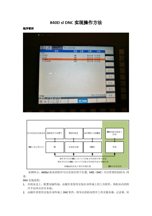
840D sl DNC实现操作方法程序管控如图所示,840Dsl机床的程序可以存放在四个位置,MES(DNC)可以管理控制的为网盘。
DNC实现流程:1.在机床边上,配置电脑终端,由操作者使用安装在该终端上的工具软件,将机床内的程序手动导出存至本地;2.由操作者使用安装在该终端上DNC软件,将导出的机床程序上传至服务器,记录谁,何时,上传,文件,DNC软件自动命名文件,进行统一管控;3.下传的流程,反之。
无法做到操作者在机床HMI上即可实现远程上传,下传程序;无法做到电脑终端之外的操作管控。
操作者说理解,因为HMI上没有办法登录MES/DNC用户,表示同意根据MES人员排班进行人员操作责任的跟踪。
我描述了目前AA线机床网盘内的程序是实时与机床内网盘目录下是一致的,操作者认为做到这步已比BB线需要人工导入的半自动要好。
所以在DNC开发完成后,我们也无法做到操作者在机床HMI上即可实现远程上传,下传程序;无法做到电脑终端之外的操作管控。
整理下具体的流程初步操作方法是这样:1.上传:操作者在HMI上,在非网盘的三个目录下,进行加工程序的修改,实际加工,试车验证无误后,在HMI上进行复制操作,将验证可用的程序复制到网盘目录下作为中转;2.网盘内按照每个机床的数控系统做文件夹。
例如,图中的SIEMENSOP50B。
3.DNC软件在监测到MES的服务器或工控机内有新文件出现,并且不是DNC软件自身的操作时,将该文件复制到中转网盘文件夹外的位置(暂时记为临时文件夹)进行存储,自动命名,例如OP50B(工位名)_19950325(修改时间)_MPF_SHIYAN(程序名)_1003(根据MES日历当天操作者ID);4.操作者(可以不是在HMI上操作的同一个人)在MES的服务器或工控机上,使用DNC软件,首先登陆自己的工号,进行确认上传,改名为,例如:OP50B_199503251638_MPF_SHIYAN_1003_199503251708(上传时间)_2004(确认上传者ID)上传成功后,文件进如最终的归档文件夹;5.下传,反之。
SlNUMERIK 840D系统人机交互程序开发方法及应用研究

通过上述关键代码操作即可实现将数值 4 赋值 态 , 为【 0 ] 时 表示 将该 子 窗体 设 置 为第 一个 状 态 , 当按 与R 1参数 。 下第一个水平软键时切换到该窗体 , 依此论推 ; 第二
和计算机软件资源结合起来【 l j 。作为一个 良好的机床 息 时 , 应用 程 序 会 发送 一 条请 求 信 息 给服 务器 , 服务 位置控制与操作人员交互信息 的平 台, 8 4 0 D提供 了 器 根据 所 提 供 的消 息 ( 地 址指 针 ) 作 出应答 以实 现数 相应 的数 据 接 口供 用 户 开发 专 用 功 能使 用 。用 户 可 据 的交互 。基 于 O E M 软件 可 以与 数控 系统 实现 的通
/ / 设定 通讯 模 式 为手 动写人
L a b e l 1 . Ca p t i o n =” 4’ ’
/ / 设定待写人 的 R参数值
840D系统NC加工程序向PLC存储器传送数据3页

840D系统NC加工程序向PLC存储器传送数据使用NC加工程序在NC和PLC数据交换区上构造S7300PLC的ANY数据类型的变量并传送给PLC,然后PLC在数据交换区上读取并传输数据到ANY变量指定的地址。
840D和840Dsl系统中,NC和PLC有高速数据交换区。
数据交换的内容可自由配置,利用这一特性可以在NC程序中配置地址信息,使数据传输到PLC存储器任一位置。
1 NC与PLC数据的传输1.1 高速数据交换区原理高速数据交换区是一块NC和PLC共享的内存区域,因此:数据从NC 到PLC即为NC把数据写入数据交换区,然后PLC从数据交换区读取这个数据。
数据从PLC到NC即为PLC把数据写入数据交换区,然后NC从数据交换区读取这个数据。
1.2 高速数据交换区的访问方式NC使用系统变量$A_DBB[n],$A_DBW[n],$A_DBD[n],$A_DBR[n]访问高速数据交换区。
PLC使用FC21访问高速数据交换区。
1.3 注意事项机床数据28150 $MC_MM_NUM_VDIVAR_ELEMENTS配置可写的数量。
系统在赋值时对变量的取值范围进行检测,如果超出范围则报警。
2 NC对高速数据交换区的访问默认情况下NC对高速数据交换区进行读操作,向数据区写数据需要要通道机床数据28150 $MC_MM_NUM_VDIVAR_ELEMENTS 配置可写的数量。
否则会出现报警。
⑴各系统变量:$A_DBB[n]用来访问1字节数据,包括BYTE,CHAR;n 为字节地址;$A_DBW[n]用来访问2字节整数;n为字节地址,应为2的整数倍;$A_DBD[n]用来访问4字节整数;n为字节地址,应为4的整数倍;$A_DBR[n]用来访问浮点数;n为字节地址,应为4的整数倍。
高速数据交换区以字节地址访问,以整数为例第一个整数$A_DBW[0],第二个整数$A_DBW[2]。
如果下标错误,例如$A_DBW[1]则报警。
西门子数控系统结构及应用(SINUMERIK 840D sl)最新版教案02第二章
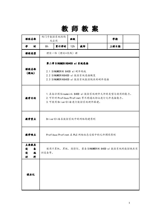
教师教案教学内容(板书)教学步骤、方法时间2.1 SINUMERIK 840D sl硬件构成西门子SINUMERIK 840D sl数控系统的硬件主要由操作部件(控制面板+操作面板)、NCU单元、伺服驱动单元、PLC I/O模块、辅助元件等几个部分组成,如图所示。
下面对这些硬件分别进行介绍。
1.操作部件SINUMERIK 840D sl数控系统的操作部件包括MCP、PCU、TCU、OP、手持单元等,主要用于在操作过程中显示相关信息并实现操作者与数控系统的人机交互HMI(Human–Machine Interaction)。
(1)机床控制面板MCP(Machine Control Panel)SINUMERIK 840D sl数控系统的控制面板主要由操作面板和辅助操作面板两部分组成,主要用于操作者与数控系统的信息交互,如输入数控加工程序、改变工作模式,调整倍率等。
运用实物演示法进行讲解,与实训室的实物进行一一对应。
讲解过程切忌生搬硬套,在使用功能的基础上进行类别细分,弱化型号名称的讲解,先使学生理解功能,再慢慢熟悉硬件。
3h教学内容(板书)教学步骤、方法时间(2)OP操作面板OP操作面板由液晶显示屏和NC操作面板组成,用于显示SINUMERIK 840D sl数控系统运行过程中的各种调试及与系统进行信息交互,如图。
(3)TCU(Thin Client Unit)TCU直译为精简型客户端单元,用于显示HMI数据,类似于家用电脑中的显卡(即GPU)或理解为无盘终端。
但TCU自身不带有硬盘,无法安装HMI软件,因此其显示的HMI数据来自于PCU或NCU内部集成的HMI软件。
(4)PCU(Personal Computer Unit)PCU直译为个人电脑单元,其功能类似于工业控制机或家用电脑的主机箱。
PCU配备有独立的CPU和硬盘,并且可在硬盘中安装HMI软件,用于人机可视化交换。
如操作、程序编辑、诊断等前台程序的运行。
西门子数控系统结构及应用(SINUMERIK 840D sl)最新版教学课件第1章
图1-4 SINUMERIK 840D数控系统
图1-5 SINUMERIK 810D数控系统
图1-6 SINUMERIK 802D数控系 统
◆2013以后,随着德国在《德国2020高技术战略》中提出德国工业4.0的概念, 西门子顺应潮流,推出了最新的SINUMERIK 840D sl,828D合808D数控系统。 2016年在4月11日至15日在上海举行的“第九届中国数控机床展览会(CCMT 2016) 上,西门子公司对上述数控系统及其相关机电产品以“迈向工业4.0之数字制造” 为主题进行了集中展示,该系列数控系统实现了全部的数字化,并能实现与IT技 术及机器人技术的高度集成。
不同点
共同点
◆最多支持4根进给轴/主轴
◆PPU型号为141.2,采用7.5'' 彩色
LCD显示屏
◆驱动器采用SINAMICS V60,伺 服电机采用SIMOTICS 1FL5型 ◆可实现手动机床操作(MM+)与数 控加工的结合 ◆最多支持5根进给轴/主轴 ◆PPU型号为160.3/PPU161.3,采 用8.4'' 彩色LCD显示器 ◆驱动器采用SINAMICS V70(数 字量)主轴伺服电机采用 SIMOTICSM-1PH1具有更快的加减 速性能、更好的定位精度及更强的 动态响应特性 ◆配备Drive Bus高速总线通讯及20
1.STEP7 STEP7是西门子公司出品的一款编程软件,用于西门子系列工控产品包括 SIMATIC S7、M7、C7和基于PC的WinAC的编程、监控和参数设置,是SIMATIC工业 软件的重要组成部分。 STEP7的软件版本包括STEP7 Basic,STEP7,STEP7 ProFessional,STEP7 Lite,STEP7 Micro等等,其中STEP7是用于S7-300/400的编程软件,编程方式可 使用LAD(Ladder—梯形图),STL(Step Ladder Instruction—步进梯形图)和 FBD(Functional Block Diagram—功能框图)三种编程语言。
西门子数控系统840D SL程序备份与报警设置
840D SL 数据备份 创建备份数据
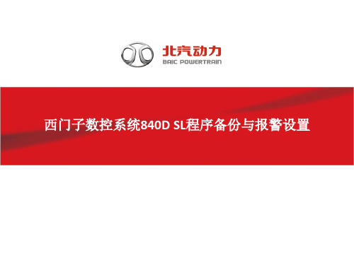
3) 系统会弹出对话框 提示选择存储位置, 在默认数据设置下, 有两个存储位置可以 选择:U盘(USB)和CF 卡(文档)。当然用 户还可以按“新建目 录”在上述存储位置 创建新的目录以存储 数据。如用光标选择 文档下的制造商上目 录,按“新建目录”
840D SL 数据备份 创建备份数据
840D SL 数据备份 创建备份数据
该备份数据存储在系 统CF上。在“调试” 区域中的“系统数据” 画面中,可以找到该 备份数据文件。
840D SL 数据备份
备份的恢复 在恢复备份前需要做NCK与PLC的总清。
NCK总清的方法 将 NCU 正面的NCK调试开关旋 转到以下开关位置
– NCK 调试开关: 开关位置 “1”。 – 按下 NCU 正面的“Reset” 键执行一次上电复位。 – NCU 被关闭并清零后重新 启动。数码管显示“6”。 –NCK 调试开关: 开关位置 “0”。 NCK总清完成。
报警设置
一.在界面上直接创建报警文本步骤
举例说明
报警设置
一.在界面上直接创建报警文本步骤
效果显示
报警设置 二 . 在计算机上编写报警文本
报警设置 二 . 在计算机上编写报警文本
报警设置
报警设置
用户报警一共有25组,从图中可以看出每 组报警有8个字节,每个字节有8位。所以 每组有64个报警,起始地址为 DB2.DBX180.0对应700000号报警,依次类 ቤተ መጻሕፍቲ ባይዱ,其中报警号中间两位和用户报警区域 的数字是一致的,从这个规律我们可以推 算出报警所对应的地址以便于维修查找。 所对应的地址=DB2.DBX(180+8*?+?) 700806
关于在外连笔记本与数控系统840D传输程序注意事项

关于在外连笔记本与数控系统840D传输程序时,应用串口传输软件Winpcin,网上关于此的使用方法很多,802D应用简单,机床侧参数无需设置,840D就稍微复杂些。
以下是设置过程(以从笔记本向数控系统发送程序为例):先连接好串口线再打开笔记本和机床(网上说是防止烧坏串口线,半信半疑);先设置机床参数使其处于等待接收状态,点击按钮Menu——服务——接口,然后设置端口COM1,记录(RTS/CTS),传送(正常)奇偶校验(无)停止位(1)数据位(8)波特率(9600)文档格式(PC二进制格式)然后点击确定——数据输入,选择零件程序或子程序文件夹,使其接收程序文件,最后点击RS232按钮,表示机床侧已启动准备接受文件任务;接下来需要设置笔记本侧的Winpcin软件,打开后,点击左下角的RS232 Config按钮,再点击右侧840D 按钮设置接口参数,与机床侧一致,Flow Control选择Hardware,directories为空,Else为空,默认即可;然后点击右侧Save & Activate——Back,选择SendData按钮选择要传送的程序文件,扩展名与上传文件夹的扩展名一致,程序内容的前面需要加上文件头(以零件程序为例)“%_N_上传的文件名_MPF(回车)
上传时程序头要加“%_N_上传的文件名_MPF(回车);
电脑端进入设备管理器中去看看,你的com到底使用的是哪个口,是否和你在Winpcin中使用的口相同,这个必须相同,是否被其他占用。
设置完后别忘了按确认键。
SIEMENS 840D NC与PLC之间的数据通讯
摘要:文章针对SIEMENS 840D NCU与PLC之间数据通讯的实现方法进行详细的说明,包括FB2/FB3、FC21的应用技术,并配合相应的举例。
关键词:840D 数据交换FB2 FC21 NC_var selectorData exchange between NC and PLC for SIEMENS 840DHU Guoqing(Wuhan Huazhong Automation Technology Devolopment Ltd.,Wuhan 430077,CHN)1.前言在数控系统调试过程中,经常需要在NC、PLC之间进行数据交换,以使整个系统都在程序控制之中,作为当今世界优秀的高端数控产品代表SIEMENS 840D,它提供了先进的通道和技术支撑,使你可以轻松地实现数据的畅通交换。
笔者根据工作过程中积累的设计与编程经验,在此就这个主题与同行探讨。
经常使用的数据交换包括M代码、T代码、H/F功能传输以及840D系统提供的功能强大的接口信号,不需叙述。
在这里只是针对一些专用数控功能应用时需用到的数据交换方法进行较详细的说明。
2.PLC读/写NC参数/变量在进行数控铣镗床滑枕低头补偿或刀库定位控制编程时,都需要用到PLC读/写NC参数或变量。
SIEMENS的8x0D toolbox中提供了FB2(GET)/FB3(PUT)功能块程序,结合使用配套的NC_var Selector软件就可实现此项功能。
其中FB2用于读取NC变量(包括MD参数和NC内部变量),FB3用于写NC变量。
2.1 NC_var Selector的使用对于读取的NC变量,应先使用NC_var Selector软件选择所需的变量,最终建立一个AWL源文件。
下面就以Ver6.4版为例说明其使用步骤:首先建立一个新的Project,在库文件打开框中根据需要选择ncv_NcData.mdb(读取NC参数)或者ncv_611d.mdb(读取611D驱动参数)等。
西门子840DSL数控系统安全集成的研究与应用

西门子840D S L 数控系统安全集成的研究与应用
张立群1, 张 义 红 112
( 1 . 上海东华大学信息科学与技术学院;2.数字化纺织服装技术教育部工程研究中心,上 海 201620)
摘 要 :本文将主要介绍数控机床领域的安全标准以及西门子840DSL数控系统安全集成技术的基本原理和功能应用。 以AFS5 - 4 0 数控外圆磨床为应用实例,介绍与西门子安全集成相关的硬件设计和软件设计,以及安全集成功能的调试与
AFS5 - 4 0 磨 床 的 数 控 系 统 采 用 最 新 款 的 西 门 子 840D Solution L ine, 伺 服 驱 动 米 用 S 12 0 数 字 伺 服 驱 动 系 统 ,P L C 采 用 S7 - 3 0 0 控 制 器 ,并 使 用 ProfiNET做 为 现 场 通 讯 总 线 ,同 时 使 用 ET200s 安 全 I/O 模 块 做 为 ProfiSAFE的 安 全 输 入 输 出 信 号 模 块,以上就构成了该机床的整套安全集成控制系统。 数控机床安全电气控制系统硬件配置如图1 所示 。
图 1 机床安全电气控制系统硬件配S
根 据 EN 9 5 4 - 1 安 全 标 准 可 将 安 全 控 制 神 类 分 为 五 档 ,即 Kat.B 、Kat.l 、Kat.2、Kat.3 和 Kat.4, 这 五 档 分 别 对 应 五 种 不 同 的 安 全 控 制 要 求 ,发 生 安 全 报 警 时 ,数 控 系 统 将 根 据 不 同 的 安 全 等 级 产 生 相 匹 配的安全防护措施。安全门锁、机床灭火器信 号 、双手操作按钮和急停按钮等信号对操作人员的 人身安全以及机床设备的财产安全起到至关重要的
用于Siemens 840D sl数控机床信息监控的顶屏软件
邢 雨 赵 亮 王 照亮
( 上海 三 一精 机 有 限公 司研 究院 电气所 , 上海 2 0 0 2 1 0 ) 摘 要: 介 绍 了用于 配备 S i e me n s 8 4 0 D s l 系统 的数 控机 床 信 息监 控 的软件 。 该 软件 结 合 实 时数 据库 技 术 , 通 过将 离散 的 P L C、 NC信 号转 换为 字 节型信 息 , 并将 字 节 型信 息 数据 采集 , 通 过 软件 以图 片 、 文 字 或 动 画方式 直观显 示在 机床 操 作显 示屏 上 , 有 利 于操作 者第 一 时间获 取机床 信 息。 关 键词 : S i e me n s 8 4 0 D s l 机床 信息 监控
刀号、 刀库门开闭信息 ; ( 3 ) 托盘 区: 显示加工 区工作
台 编号 、 待机 台是 否 到 位 信 息 ; ( 4 ) 辅助功能 区: 显 示 冷 却方式 、 机 床照 明 、 润滑 、 安全 门等 信 息 ; ( 5 ) 系 统 功 能区 : 当前操 作等级 、 系统版本 、 系统运 行 时间等 。
s h o ws p i c t ur e,t e x t o r a n i ma t i o n d i r e c t l y o n t h e ma c h i n e s c r e e n . Th i s me t h o d i s f a v o r a b l e t o a c q u i r e ma — c h i n e i n f o ma r t i o n i n t i me f o r t h e o p e r a t o r s . Ke y wor ds : S i e me n s 8 4 0D s l ;M a c hi ne I n f o m a r t i o n Mo n i t o r i n g;Up p e r s c r e e n S o f t wa r e
SINUMERIK 840D sl 软件安装与操作指南说明书
s SINUMERIK 840D sl2016-03-31CNC Software 4.7 SP2 HF4Installation and Operating NotesThe CNC Software 4.7 SP2 HF4 (internal Version 04.07.02.04.005) comprises the following components:Component VersionNCK (incl. NRK) V99.17.07SNCK V02.06.02.00.002SINAMICS V04.70.35.46PLC OpSys (317-3) V32.83.23PLC OpSys (319-3) V32.83.23FB15(sl) 04.07.26CP V02.34.00MCP_CLIENT V01.06.04SINUMERIK Operate V04.07.02.04.002Linux basic system V04.70.80NCK file system driver V04.07.01.01.001NCU-Link Config V03.00.00(SDBs for the configuration of NCU-Link)Profinet FW 14.01.06.04Cycles V04.07.62.03HMIARC Tool 04.05.02.00.003SinIntClient 03.00.04.00.045Requirements:o CNC SW 4.7 SP2 HFx may only be operated on SINUMERIK NCUs 710.3 PN / 710.3B PN, 720.3 PN / 720.3B PN and 730.3 PN / 730.3B PN.o CF card Smart Modular Xceed 8GB. - For the standard version 6FC5851-1XG41-2YA8.o Step 7 version as from V5.5 SP4o Current toolbox from and including V 04.07.23.00o NCU service system from and including V04.70.47o For the use of SINUMERIK Operate internally on NCU, you require the option S00 SINUMERIK Operate on /NCU in combination with real driveso For the use of SINUMERIK Operate externally on PCU or PC, you require the option P87/P88 SINUMERIK Operate on /PCU / PC in combination with real driveso NCU 7x0.3 modules with boot code of PLC version V2.5 (see also the point "Boot code..")**********************************************************************************************************************New options V4.7 SP2 HF1 and higher:6FC5800-0AS14-0YB0 Orientation Offset6FC5800-0AP77-0YB0 CNC user memory expanded6FC5800-0AP80-0YB0 Extended Touch6FC5800-0AP73-0YB0 Run MyRobot /Machining© Siemens AG 2016DF MC R&D 51Page 1 of 12Notes and restrictions:The Software HMI-Pro sl as from including V04.05.03.04 can be used in combination with CNC SW 4.7 SP2 HFx.Additional languages V4.5.2 and V4.7.2.1 are supported. New texts from SW 4.7 SP2 HF1 are possibly displayed in English.The following functions / options have not been released:• F-PLC, that means no 317F or 319F, nor SINUMERIK with dbSI1 either• HTL/TTL encoder in combination with HLA and Safety• The CBA function may only be used together with a declaration regarding the machine-specific approval. • AST from part program (ASTCMD): no support of gantry axes• The Easy-XML functionality included in Operate may not be used by customers for configuring.********************************************************************************************************************** Functional improvements in Operate SW 4.7 SP2 HF4 compared to SW 4.7 SP2 HF3:PR No. 461181 465929 455882 455890 455893Functional improvements in Siemens Cycles SW 4.7 SP2 HF4 compared to SW 4.7 SP2 HF3:PR / RQ 463950 465889 465355Functional improvements in NCK SW 4.7 SP2 HF4 compared to SW 4.7 SP2 HF3:PR No. 454805Functional improvements in Operate SW 4.7 SP2 HF3 compared to SW 4.7 SP2 HF1:PR / RQ 437375 44441 445573 451745Functional improvements in Siemens cycles SW 4.7 SP2 HF3 compared to SW 4.7 SP2 HF1:PR / RQ 435158 441514 441517 436813 451189Functional improvements Linux basic system SW 4.7 SP2 HF3 compared to SW 4.7 SP2 HF1:PR / RQ 408616 427875Functional improvements in NCK SW 4.7 SP2 HF1 compared to SW 4.7 SP1 HF1:PR No. 223981 223983 224078 224176 224329 224590 224719 225480 225635 225760 226113 226134 226226 298293 298481 299426 311840 317281 322349 329598 330513 332500 334927 335256 356081 336706 336721 337226 339418 340140 340469 340814 344404 345306 345306 345762 346665 348212 348713 349183 351642 353091 353472 353606 355123 355443 356904 356907 357128 357174 357822 358272 358656 359001 359007 359927 360178 360543 360550 363495 364464 365308 365574 365731 366094 366094 366166 366484 366717 367592 368094 368634 369953 370430 371206 372680 372954 374197 375457 376765 377148 377151 377151 378642 378767 378869 379143 379474 379474 380340 380731 381765 381791 381959 382053 383143 383202 383208 385000 386211 386315 386315 388342 388342 388836 388926 389770 390300 390330 390364 390847 390847 391660 391807 392293 392304 392400 393820 393820 394144 395547 395852 396459 397177 398392 399256 399309 399812 400045 400273 400639 400854 401008 401503© Siemens AG 2016DF MC R&D 51Page 2 of 12401624 402119 402119 403479 404601 405164 406539 406851 408564 409450 409932 410433 410735 411246 413392 419084 419596 424109 Functional improvements in Operate SW 4.7 SP2 HF1 compared to SW 4.7 SP1 HF1:PR No. 223769 223877 224056 224314 224321 224420 224481 225104 225904 225990 226232 226394 300402 318491 322713 324767 325498 334331 334930 335016 336851 337082 339022 339874 340344 340651 350129 350201 352254 352355 352904 353281 353659 353721 356266 356357 358778 359281 360403 360583 361217 361546 362217 363278 364038 364238 364492 364495 365162 365844 366901 367682 367682 368327 368374 368377 368806 369484 370560 371357 371446 372141 372477 372803 372809 372813 372835 373319 373487 373742 375180 375385 375424 375787 375794 376538 376966 377115 377593 377808 378142 378372 378694 379569 379915 379915 380434 380460 380670 381296 381305 381359 381527 381736 381736 381964 382114 382792 382792 382808 383158 383309 383345 383345 383795 383801 384398 384407 384407 385018 385018 385251 386383 386625 386747 386747 386773 387108 387108 387108 387251 387318 387371 387381 388054 388181 388186 388486 388823 388823 388827 389701 390346 390643 390643 390815 390846 390859 391306 391741 391741 392208 392211 392211 392233 392583 392752 392752 392752 392757 392899 393278 393278 393326 393509 394148 394573 394852 395130 395738 395765 395906 396445 397037 397143 397145 397394 397810 398509 398771 398926 400490 401097 401671 401728 402009 402009 402313 404475 405164 405389 405534 405809 405819 405876 406189 406215 406238 407561 408062 408733 409450 409693 410119 410502 410914 410914 411432 411589 411594 411853 411922 412540 413754 414566 414906 414983 415201 415564 416534 416554 416878 417248 417387 418708 418739 418887 419987 420012 420250 420484 420585 421635 421967 422428 424217 424217 424279 425359 425595 425788 425788 426349 426349 429419 430121 431275 433293 435149 435186 435206 435295 Functional improvements in the Siemens cycles SW 4.7 SP2 HF1 compared to SW 4.7 SP1 HF1:PR No. 223970 224912 225633 226202 287498 307345 310522 311986 327348 333374 339325 345012 345810 347320 348287 350523 359436 359618 360164 364202 364204 371395 371797 375783 376496 376853 377231 377615 377647 378440 379727 379881 380089 380126 380767 380978 381187 381218 381340 381903 383997 385847 385863 386148 388506 389579 389655 390706 392172 392172 392399 392399 392418 392418 392759 392876 392876 392876 393069 393196 393222 393222 394495 394573 396311 396402 397048 398912 399203 399281 399873 399903 400110 400110 400335 400382 401081 401723 401973 402889 402889 405380 408989 409008 409932 409932 409932 410650 411532 412362 413543 414764 416760 420751 424630 426834 428054 431605 Installing the CNC software:The NCU service system >= V04.70.47 is required on a USB stick to install the CNC software.New installations can be performed via the NCU service system and TCU or with WinSCP / AMM /P2P fromV4.6 SP1 HFx.An upgrade or new installation can also be carried out using the tools of the Create MyConfig Version from 4.6 HF1. To do this, a CMC package must be generated that is stored and booted either on a PG, PC, a PCU or a © Siemens AG 2016DF MC R&D 51Page 3 of 12USB stick at the NCU or PCU. The instructions can be found in the Create MyConfig manual.The software may only be installed on a SINUMERIK 8GB CF card – see prerequisites.Boot code of the PLC:Software release 4.7 only starts with PLC boot code V2.5 (or later) internally coded on the NCU hardware.If this PLC boot code has still not been installed, the control will not start (in the 7-segment display"PLC" and SF and DP LED flash red).In this state, the bootcode upgrade can be initiated by actuating the PLC rotary switch. The bootcode is flashed by turning the PLC rotary switch into position 5. This can be identified by the factthat a rotating wheel is displayed in the 7-segment display. This takes approx. 15 seconds. With this procedure, under no circumstances is it permissible that the NCU is switched off! The 7-segment display goes dark after the boot code upgrade has been completed. The PLC rotary switch can now be turned back to position 3 (memory reset) and the system continues to boot.Installing the NCU service system on USB stick:The NCU service system is stored as a USB stick image in directory emergency_bootsys_ncu on the supplied DVD. The copy program installdisk.exe is also included. Connect a USB stick >= 2 GB to your PG resp. PC and determine the relevant drive letters. Call installdisk to copy the NCU service system to the USB stick: installdisk --verbose --blocksize 1m <Image file> <Drive letter:>It is best if the command specified above is executed in a DOS shell.For this, you require administrator rights on your PG / PC.Installation on the NCU:Upon completion of installdisk, remove the USB stick from the PG / PC, boot once an NCU 7x0 from this stick (this boot process takes a little bit longer; a "P" in the 7-segment display of the NCU indicates that the FAT partition of the USB stick is partitioned) and reinsert the stick in the PG / PC. Under Windows, you can now see an empty USB stick. Now copy the desired CNC software (file with extension .tgz) from directory ncu_sw on the DVD supplied to this USB stick.The USB stick can be connected to one of the two USB connectors of the NCU 7x0.3. The NCU will boot from this USB stick after power ON. The system is operated either via a TCU that is connected to the NCU, or via PG / PC using WinSCP under "Open Terminal".Instructions on how to use the NCU service system can be found in documentation /IM7/ on the DVD supplied. We recommend that you use the USB stick "SIMATIC IPC USB Flashdrive, 6ES7648-0DC60-0AA0". Alternatively, the image can be installed using the AccessMyMaschine /P2P tool V4.6 SP1 HFx via the menu item "Write file system image..." dialog.Notes on the CNC software:o The NC option alarm is a Power-On alarm with the standard and export versions.Exception: Simulators without real Drives.o When upgrading the system from V4.5 SPx and having licensed all options, the options P87 and P88 (Operate on PC resp. PCU 50) may have to be licensed subsequently following the upgrade.o Before reading in a data backup, perform a general reset of NC and PLC using the switches NCK / PLC.o Auto Servo Tuning - ASTWhen upgrading your system from CNC SW < V4.5 SP3, the stored AST session files (Auto ServoTuning) are not compatible and the AST settings (strategy, measurement parameters, etc.) get lost.o SinuComARCSeries commissioning archives can no longer be edited with SinuComArc.Alternatively, you can use Create MyConfig (e.g..: also CMC Diff) resp. AMM /P2P V4.6 SP1 HF2: Does not claim to be a compatible successur.© Siemens AG 2016DF MC R&D 51Page 4 of 12o In the screen "Logical drives", display faults regarding the configured USB interfaces may occur.o In the screen "Logical drives ", you should not configure network drives which are not permanently available.o Restrictions with EES:When using a USB stick on the TCU in combination with a PCU, you can currently not edit any files on the USB stick with active EES mode. These files can, however, be executed.If a USB stick on a TCU is accessed by several HMIs / NCUs in parallel, the components are notcoordinated. This entails the danger that a program being processed is modified / destroyed by another component.o When using SinuComNC trace, you must ensure with PLC signals that the configured signals (data blocks, data bytes) are provided in the PLC.o Problem solution for S5_FETCH / S5_WRITE in the CP:As from SW 4.7 SP1, the file cp_param.ini, which contains the following contents, is stored on the CF card in the directory /siemens/sinumerk/cp:[IniFile_ID]Version = 100Type = 'CosCP'Comment = 'Select fetch/write version'################################################################################ #### If you modify this file, ######## - don't remove the section [IniFile_ID] above ######## - check 'cp_param.log' to verify that your settings are accepted. #################################################################################### [FetchWrite]# Selection of the S5 fetch/write implementation# Version = 1 : the previous behavior# Version = 2 : the new as far as possible CP 343 compatible behaviorVersion = 1The problem solution besomes active when recopying this file (possible as manufact) into the directory /user/sinumerik/cp and modifying the entry "Version = 1" in "Version = 2".o When traversing with low speeds alarm 27011 is triggered during traversing motions in the negative direction.The following supplementary conditions must be considered as remedy for the described behavior:The minimum possible resolution (quantization) of the monitoring functions for Safety Integrated is 1increment per monitoring clock cycle [incr/mcc].Two increments per monitoring clock cycle are necessary, so that no speed violation alarm is triggered when the axis is stationary.The minimum speed limit value that can be set for the machine data $MA_SAFE_VELO_LIMIT can be determined as follows:For a rotary axis:$MA_SAFE_VELO_LIMIT[rpm] = 2[incr/mcc] * 60[s/min] / 360[degrees/rev] / 1000[incr/degrees] /MCC[s/mcc]Example 1: Monitoring clock cycle=12ms, LimitMin=2[incr/mcc]$MA_SAFE_VELO_LIMIT = 2[incr/mcc] * 60 [s/min] / 360 [degrees/rev] / 1000 [incr/degrees] / 0.012[s/mcc] = 0.02777.. [rpm] => rounded 0.028[rpm]Example 2: Monitoring clock cycle=8ms, LimitMin=2[incr/mcc]$MA_SAFE_VELO_LIMIT = 2[incr/mcc] * 60 [s/min] / 360 [degrees/rev] / 1000 [incr/degrees] / 0.008[s/mcc] = 0.04166.. [rpm] => rounded 0.042[rpm]With decimal places the value has to be rounded to be entered for the machine data.© Siemens AG 2016DF MC R&D 51Page 5 of 12For a linear axis:$MA_SAFE_VELO_LIMIT[mm/min] = 2[incr/mcc] * 60[s/min] / 1000[incr/mm] / MCC[s/mcc]Example 1: Monitoring clock cycle=12ms, LimitMin=2[incr/mcc]$MA_SAFE_VELO_LIMIT[mm/min] = 2[incr/mcc] * 60[s/min] / 1000[incr/mm] / 0.012[s/mcc] =10[mm/min]Example 2: Monitoring clock cycle=8ms, LimitMin=2[incr/mcc]$MA_SAFE_VELO_LIMIT[mm/min] = 2[incr/mcc] * 60[s/min] / 1000[incr/mm] / 0.008[s/mcc] =15[mm/min]With decimal places the value has to be rounded to be entered for the machine data.Actual speed value:With very low speeds the possible minimum resolution of the actual speed value must also beconsidered; this value depends on the encoder pulses per revolution, the gear ratio and the monitoring clock cycle!SINAMICS display parameters for the speed resolution:The drive provides a display parameter for the speed resolution, which is also visible with ncSIr9732[0..1] SI Motion speed resolutionFor index 0:Display of the safe speed resolution (load side). Specification of speed limits or parameter changes for speeds below this threshold have no effect.For index 1: Display of the safe speed accuracy based on the safe encoder accuracy. Unit: mm/min or rpmUse for ncSI:With a 1-encoder-system the above mentioned display parameter r9732[0..1] “SI Motion velocityresolution” can be used as a basis for the setting of the minimum limit values by the user. Double the value displayed in r9732[0] is necessary for parameterization, so that no speed violation alarm istriggered when the axis is stationary.With a 2-encoder-system the value displayed for r9732 is only valid for the encoder parameterized for SINAMICS. The speed resolution of the encoder for the NCK can vary from this value!As already stated above, this parameter alone does not provide any information on the actual accuracy of the speed measurement. This depends on the type of actual value sensing, the gear ratios and the quality of the encoders used!o Adjustment of the default machine data in the area "Saving of persistent data".With the values set, the number of write processes onto the CF card has been reduced on the CF card.a) Change of the memory default values for saving persistent data on the system CF cardalt newN17610 $MN_DEPTH_OF_LOGFILE_OPT_PF[0]= 10 100N17610 $MN_DEPTH_OF_LOGFILE_OPT_PF[1]= 0 10N17610 $MN_DEPTH_OF_LOGFILE_OPT_PF[2]= 0 30N18232 $MN_MM_ACTFILESYS_LOG_FILE_MEM[0]= 2 400N18232 $MN_MM_ACTFILESYS_LOG_FILE_MEM[1]= 3 50N18232 $MN_MM_ACTFILESYS_LOG_FILE_MEM[2]= 3 30b) In order to keep the preprocess running during the Flush process, the system has been set toasynchronous flush by default.N18234 $MN_MM_MEMORY_CONFIG_MASK= 1Note:After loading the archive, the new default values remain only topical if the “old“ default values are not changed and an archive has been created with© Siemens AG 2016DF MC R&D 51Page 6 of 12MD11210=FFMD11212=1.© Siemens AG 2016DF MC R&D 51Page 7 of 12© Siemens AG 2016 DF MC R&D 51 Page 8 of 12o Safety/Diagnostics: No display of the SAFE.SPF checksumIf, in SAFE.SPF, the line with the variable SAFE_CHECKSUM is not displayed in line 1, no checksum is displayed for SAFE.SPF under Safety/DIAGNOSTICS/checksums.Solution:; SAFE_CHECKSUM = xxxxxxmust be displayed in the first line.o SSH Port 22 on X130 interfaceFor security reasons, the SSH port 22 on the X130 interface is disabled in der firewall as from SW 4.7 SP1. As a consequence, the controller can no longer be accessed from external sources via thisinterface. This concerns, among others, Operate on PCU/IPC/PC (which uses this for several functions), WinSCP and AMM.This port can be permanently activated in Operate (only possible on the NCU) under Commissioning -> Network -> Company network -> Change -> Checkbox “SSH (TCP/22)“, see screenshot:Alternatively, you can make a manual entry in the file /user/system/etc/basesys.ini (such as the ports102 and 5900 are activated).Notes on the Toolbox V04.07.23:With Toolbox V04.07.23 we recommend the use of STEP7 V5.5 SP4 HF7.If no new functions from Software 4.7 are used, you need not upgrade the PLC user program to the basic program Version 4.7. PLC basic user programs Version 4.5 (or later) are functional.When configuring an HLA hardware, you may only change telegrams as from slot (Object) 1 from 136 to 166.S120 drives on the Profinet isochronous:Configuring via the NCU is supported, not via the IO device.With an isochronous alarm of the NCU, select the setting for the Ti/To mode as “fixed“ rather than “in IO device“.© Siemens AG 2016DF MC R&D 51 Page 9 of 12Module replacement STEP7 Hardware Config:With STEP7 5.5 SP4 HF4, you cannot replace an NCU710.3 PN by another NCU in the HW Config. We recommend that you use STEP7 5.5 SP4 HF3 (or lower).Notes on the Toolbox V04.07.22:Upgrading the system SW to 4.7 by using the existing PLC user-program causes a problem to arise with the Toolbox >= 4.7.21 at the call interface of the FB1 in the OB100.Inserting the new parameter "MCP_IF_TCS" results in a change to the call interface of the FB1. Thiscauses the user to receive an error message from Step7 after inserting the blocks from the Toolbox >=4.7.21.The error message only occurs if the OB100 is opened© Siemens AG 2016 DF MC R&D 51 Page 10 of 12This situation has improved in Toolbox V04.07.23, the block call FB1 "RUN_UP" has to be updated once and then the call parameters are displayed without any time stamp conflict.Notes on the use of the Starter:Starter-Version V4.4 SP1 or higher must be used.Notes on SINUMERIK Operate:When using SIMATIC ITC panels, no touch softkey is available for the help function.The mold and die view cannot be used with POLY and G91 statements.The mold and die view cannot be used with BSPLINE statements.Only the elements 0 to max. 65534 can be displayed or changed in GUD arrays, even if the array isgreater in the NC.Function "Programlist" without Option EES (P75):The softkey "Program select" generates a listentry //NC :/....The double point must be deleted:Programlist for …USER“ (in operating area Program manager)System CF /card/user/sinumerik/hmi/plc/programlist/plc_proglist_user.ppl.Programlist für …OEM“ (in operating area Setup)System CF /card/oem/sinumerik/hmi/plc/programlist/plc_proglist_manufacturer.pplThe OEM password is required for these modifications.Mark block, Menu Edit > Call > UpdateNew designA new “skin” (new design) has been added to Operate. This new skin changes the appearances of thesoftkeys incl. the icons on the softkeys, the appearance of the window title bars, various colors (window background colors) and the appearance / behavior of the header – the displays for the operating area and operating mode can be found on the right side of the header line and, with no alarm pending, theheader only shows the Siemens logo.The new skin can be activated via the display MD 9112 HMI_SKIN = 1. After a restart, Operate uses the new skin.With multi-touch operation (e.g. OP015 black / OP019 black) the functions of the user interface have also been expanded. There are six function keys above the vertical softkeys which are always visible for the functions Undo, Redo, Open/close online help, Open/close virtual keyboard, Open/close calculator, Create screenshot.We recommend a color depth of 32 bit for the new design.At the moment, the internal Operate is operated with a color depth of 16 bit. If the color depth is to beincreased to 32 bit for use with the new skin, the entry QWS_DEPTH in the [Environment] section of the run_hmi.ini file must be set to the value 32:[Environment]QWS_DEPTH=32A corresponding file with the name run_hmi_colordepth32.ini is supplied in the template directory. Copythis into the /user/sinumerik/hmi/cfg directory and change the name to run_hmi.ini.When executing part programs from network drives or editing files on network drives, the user mustprovide for a stable, interference-free network connection to the network drives.© Siemens AG 2016DF MC R&D 51Page 11 of 12Cycle packages:CNC SW 4.7 SP2 HFx contains the following cycle packages on the CF card:Standard cycles (technological cycles)Measuring cyclesISO cyclesShopMill cyclesShopTurn cyclesGrinding cyclesAST cyclesAdapting CyclesAll these Siemens cycles are automatically loaded into the NC during the runup of the NCU. The corresponding variables are stored in the definition file PGUD.Note:The “programGUIDE“ in SINUMERIK Operate is based on the cycle packages of CNC SW 4.7 SP1.Cycle calls in part programs for these cycles cannot be recompiled or processed with the cycle support in HMI-Advanced 7.x.For further information and notes, see siemensd/e_appendix_cycles.pdf.© Siemens AG 2016DF MC R&D 51Page 12 of 12。
西门子840Dsl数控系统OPC UA的配置与应用

2019.24科学技术创新西门子840Dsl 数控系统OPC UA 的配置与应用闵家林吕毅徐园园(西安智熔金属打印系统有限公司,陕西西安710000)在数控系统的内部,我们关心的数据都是以系统内部变量的方式存储在相应的“地址”中的,如果可以通过以太网协议(现在的数控系统基本都具备了以太网接口)将这些数值提取出来并送到上位电脑(也称为上位机,数据采集服务器),之后通过统计学,IT 技术等其他学科的知识完成对已采集数据的后续处理。
在机加工生产车间,除了机床外,其他辅助设备如刀具预调仪,工件测量机如果支持相应的网络数据传输协议也可以连接到工厂网络中。
SINUMERIK 828/840Dsl 数控系统可以通过软件选项功能(6FC5800-0AP67-0YB0)激活SINUMERIK OPC UA 服务器,提供一个基于制造商独立标准的通讯接口,SINUMERIK 控制信息可通过该通讯接口与OPC UA 客户端进行交换,实现安全、可靠并独立于制造厂商的原始数据和预处理的信息从制造层级到生产计划或ERP 层级的传输。
通过OPC UA ,所有需要的信息在任何时间,任何地点对每个授权的应用,每个授权的人员都可用。
1SINUMERIK OPC UA 服务器设置1.1设置授权目前西门子只有4.5及以上版本的系统软件或4.7版本系统软件支持OPC UA 功能。
本文介绍SINUMERIK Operate 软件版本V4.7的设置。
通过操作区域调试>授权设置Access MyMachine /OPC UA(6FC5800-0AP67-0YB0)的授权。
重启SINUMERIK Operate ,使授权生效。
1.2设置OPC UA 系统重启后,在调试>网络,可以看到右侧第四个按键位置出现OPC UA 按键。
点击OPC UA 按键>更改,根据选用的是NCU 的X130网口,还是PCU50的X1网口,将相对应的IP 地址填写进去。
基于西门子840Dsl系统的四轴同步运动控制实现
基于西门子840Dsl系统的四轴同步运动控制实现发布时间:2022-09-13T02:07:58.492Z 来源:《科学与技术》2022年第5月9期作者:张锦成杨万叶[导读] 在西门子840Dsl系统实现四轴同步运动控制的基础上,折边机滑块部件四轴曲柄连杆的位置-速度同步运动控制主要通过多轴龙门控制方案实现张锦成杨万叶广西玉柴机器股份有限公司广西玉林市 537000摘要:在西门子840Dsl系统实现四轴同步运动控制的基础上,折边机滑块部件四轴曲柄连杆的位置-速度同步运动控制主要通过多轴龙门控制方案实现。
本文结合西门子840Dsl系统的应用开发,对四轴龙门运动控制的实现进行了研究。
关键词:西门子840Dsl系统;四轴同步运动;控制当前,伺服同步控制技术是折边机和折弯机滑块控制领域的一个发展方向。
采用伺服电机通过减速器直接驱动滑块,与传统液压控制相比,具有更高的响应速度及控制精度,降低了传统液压系统的复杂性、能耗、噪声。
此外,由于常规电子齿轮运动控制的控制精度较低且难以实现,因此研究基于西门子840Dsl系统的四轴同步运动控制意义重大。
一、西门子840Dsl数控系统西门子840Dsl数控系统,采用一种开放式设计结构,不仅双乳应用于数控机床,也能应用于运动控制领域,通过系统本身强大的工业通讯网络,可设计成开环或闭,实现柔性生产。
840Dsl系统分成三部分: 1、HMI,人机交互。
主要由人机单元PCU、机床控制面板MCP,以及键盘鼠标、选配的触摸屏等组成,实现加工与仿真、数据管理、上位机通讯等。
2、控制、通讯系统。
主要有数控单元NCU、可编程控制器PLC,以及外围通讯模块、输入输出模块等,实现插补运算、运动控制、数字量模拟量控制等。
3、S120驱动系统。
主要由S120驱动系统、1FK系列伺服电机,具有节能、高动态、稳定可靠的进行轴向运动、插补等优点,另外,S120驱动系统可单独与其他西门子工业自动化产品组合,作为运动控制系统。
西门子840Dsl网盘程序传输设置方法

西门子840Dsl网盘程序传输设置方法840Dsl网盘进行程序传输具有稳定、安全、快速、便捷等特点。
首先使用以太网传输(稳定),可以设置系统的访问权限(安全),实现程序的快速传入传出(快速),并且像访问NC目录一样对网盘中的内容进行操作(便捷)。
具体设置过程如下示例:硬件:840Dsl软件:V4.5SP11、先找根普通的网线(注意两头要有接头哦)2、打开机床后面的电气柜门,如下图,本机床中驱动器最右边是NCU,打开NCU的盖子,就可以找到X130网线接口(有些机床的X130口已经被机床厂扩展链接到外部,直接连接即可)。
将网线插进,盖好盖子就OK了。
3、将网线顺着控制柜出线口迁出另外一头到电脑主机的接线口上,就完成了网线的连接。
4、西门子系统侧先要修改系统权限?点击M键?右边MENUSELECT键?调试键?在右竖排可以看到口令键?输入口令:SUNRISE ?确认。
5、接下来开始机床侧的网络TCP/IP设置。
进入“诊断”界面;TCP/IP诊断;TCP/IP配置;IP地址配置过程如下:6、本例中设置数控系统网址为:192.168.100.1,注意最后需要断电重启,以上是机床侧网络地址的设置。
7、接下来就要在电脑端进行设置了。
在电脑里新建一个文件夹(注意文件夹的名称必须为英文,如“SIEMENS”)接着右键设置共享8、机床上电后电脑就会出现正在识别网络符号,点击网络连接标识。
点属性设置电脑侧的TCP/IP;设置地址与机床侧在同一网段,点击确定;通过ping指令,出现以下画面就说明网络连通了。
9、接下来,对数控系统进行网盘设置操作;注意填写以上内容,尤其是用户名和密码;用户名111密码LZA(注:这是电脑的用户名和密码哦)最后点击右下角的确认符号,在系统加工程序菜单出现如下界面;10、成功了[鼓掌]最后你在电脑侧新建的程序就可以出现在机床侧的文件里了。
注意:从SINUMERIK 系统软件版本4.5 SP2起,TCP端口102(S7软件PLCprogramming tool通讯)和5900(VNC远程控制)系统默认是关闭的,使用系统的X130网口进行数据通讯时,为了使用S7在线连接或者远程控制,端口102,5900和22(RCS使用)必须在防火墙里手动打开。
西门子数控系统结构及应用(SINUMERIK 840D sl)最新版教学课件第10章

(1)创建用户 打 开 FileZilla-Server 软 件 , 单 击 “ Edit” ——>单 击 “ User ” ——>单 击
“Page”下的“General”——>单击右侧“Add” ——>在弹出的对话框中输 入用户名,如“AAA”,——>勾选“Password”,输入“123456”——>单击
1.计算机端设置 (1)关闭计算机的防火墙及杀毒软件。 (2)在计算机任意盘(如F盘)下新建一个文件夹,此文件用于存放传输程序。单击鼠 标右键——>单击“新建”——>选择“文件夹(F)”,文件夹命名为:“SIEMENS”。文 件夹的名称一定要以字母命名,放入加工程序例如“Testprogram”,如图10-1所示。
图10-1 新建文件夹
(3)设置共享权限,单击
——>单击“控制gt;单击“网络和共享中心”——>单击“更改高级共享设
置”——>单击选择“关闭密码保护共享”,其他选项为启用或允许——>单击
“保存修改”,如图10-2所示。
图10-2 共享设置
(4)为新建文件夹“SIEMENS”设置共享,在已命名的“SIEMENS”文件 夹上单击鼠标右键——>单击“共享”——>选择“特定用户”——>在“文件 共享”对话框下单击下拉菜单——>选择“Everyone”选项——> 单击“添 加”——>选中下面的“Every one读取” ——>单击右下角“共享”按钮,如 图10-3所示。
图10-7 设置逻辑驱动器
3.程序传输验证 完成以上设置后,网线插入计算机连接到840D sl系统端NCU板的X130网口。单击操作面
板按键“菜单”——>依次按下“程序”——>“SIEMENS”软键,出现如图10-8所示界面,可 以看到计算机端的程序“Testprogram.SPF”,光标选中该文件,单击“打开”——>“执行” 软键,840D sl系统进入“自动操作方式”,然后按MCP面板上“CYCLE START”启动键,执 行“Testprogram”加工程序,可实现在线加工,如图10-8所示。
- 1、下载文档前请自行甄别文档内容的完整性,平台不提供额外的编辑、内容补充、找答案等附加服务。
- 2、"仅部分预览"的文档,不可在线预览部分如存在完整性等问题,可反馈申请退款(可完整预览的文档不适用该条件!)。
- 3、如文档侵犯您的权益,请联系客服反馈,我们会尽快为您处理(人工客服工作时间:9:00-18:30)。
西门子840Dsl数控系统数据传输软件设计及实现作者:***来源:《电脑知识与技术》2022年第10期摘要:该设计以现场应用为导向,通过比较西门子840Dsl数控系统数据传输软件的开发方式,基于SCP协议,设计了一种数据传输方法,通过西门子840Dsl免费公开的少量接口,以软件的方式解决了控制端与840Dsl数控系统的人机交互问题,并且在Visual Studio 2013环境下实现了840Dsl数据传输软件,达到了设计目标。
关键词:SCP协议;840Dsl;人机交互中图分类号:TP301 文献标识码:A文章编号:1009-3044(2022)10-0107-031 概述在智能制造中,实现PC与数控系统正常运行所需要的各种系统参数和加工程序间的通讯,即通过程序的自动化方式将数控加工程序与工艺参数传送至数控机床是非常重要的一个环节,这也是对数控机床进行数据采集的基础。
鉴于上飞公司零件加工中心装备了大量基于西门子840Dsl数控系统的各类机床,因此研究PC与西门子840Dsl数控系统的通讯交互是件非常有意义的工作。
在目前PC与数控系统的通讯方式上,主要为CMI通讯方式(如图1所示),即由于西门子数控系统的封闭性,要实现PC端与其数据传输,每台数控设备需要花费一笔不小的许可证费用(3000元人民币)向西门子公司购买与设备进行通讯的软件许可接口。
在实现与西门子数控系统数据传输的环节上,基本上都要基于该接口来完成相关应用的开发,花费较大。
针对PC与西门子840Dsl数控系统数据传输实现上产生较高经济成本的问题,在不违反西门子数控系统许可证条例的前提下,本文设计了一种基于WinSCP的数据传输方法,只需通过西门子840Dsl免费公开的少量接口[1],以軟件开发的方式解决了PC端与840Dsl数控系统的数据传输交互问题,且不需要任何许可证费用,显著降低了智能制造成本。
本文从CMI通讯方式和自行设计的基于WinSCP方式等两种方案对西门子840Dsl数控系统数据传输软件进行设计并予以实现。
2 CMI通讯方式CMI通讯方式的全称为Create MyInterface,为西门子嵌入式控制器同时具有PLC的健壮性及PC的高速和开放性,可将控制功能、显示功能、工艺功能等集成于一个控制器中。
西门子嵌入式控制器与PLC一样使用STEP 7组态软件进行组态和编程,支持所有的PLC编程语言。
同时西门子嵌入式控制器提供了开放式开发包WinAC ODK以支持用户使用Microsft Visual Studio集成开发环境和C/C++/VB/C#等进行二次开发。
由于普通PC机不能适应工业环境(温度范围宽、震动大、电磁环境复杂),所以西门子根据工业环境要求对PC硬件进行重新设计,推出了西门子嵌入式控制器。
西门子嵌入式控制器分两个系列,一个是按照S7-300规格设计的S7-mEC(S7模块化嵌入式控制器),目前的型号有EC31;另一个是嵌入式工控机平台,目前有IPC427C套件和IPC477C套件。
简单归纳,西门子嵌入式控制器在功能上相当于一台传统PLC加上一台PC机,在出厂时已预装好操作系统和WinAC RTX软件,这样在功能上相当于两个操作系统,一个是通用操作系统(Windows),一个是实时操作系统(WinAC RTX)。
在Windows下开发程序需要Windows SDK(RTX SDK)和集成开发环境(Visual Studio)等相互配合。
WinAC RTX软件提供的基础开发包是RTX SDK(WinAC RTX即是使用RTX SDK开发的),结合Visual Studio集成开发环境可开发在RTX下运行的实时应用程序[1]。
WinAC ODK 则是提供了一些应用程序接口来使得用户开发的在Windows或RTX下运行的程序可以与WinAC RTX通信。
如果要开发在Windows下运行且与WinAC RTX通信的应用程序,则需要Visual Studio集成开发环境和WinAC ODK。
如果要开发在RTX下运行且与WinAC RTX通信的应用程序,则需要RTX SDK、Visual Studio集成开发环境和WinAC ODK。
如果要开发在RTX下运行但不与WinAC RTX通信的应用程序,则只需要RTX SDK、Visual Studio集成开发环境。
在RTX下运行的用户程序需要RTX Runtime的支持,RTX Runtime在WinAC RTX 安装时已被安装,所以在西门子嵌入式控制器上运行用户开发的在RTX下运行的程序前不需要安装RTX Runtime。
使用WinAC ODK时需要购买WinAC ODK开发授权,用WinAC ODK 开发生成的应用程序的运行无需授权。
WinAC ODK包含三种接口形式:CCX、SMX和CMI。
使用CCX,可开发生成Windows下运行的dll文件和RTX下运行的rtdll文件。
可以在WinAC RTX的PLC程序中先使用SFB65001创建CCX对象(dll文件或rtdll文件)的实例,然后使用SFB65002(同步调用)或SFB65003(异步调用)来调用CCX对象,以扩展WinAC RTX的功能。
使用SMX,可开发生成Windows下运行的.exe可执行文件和RTX下运行的.rtss可执行文件。
这些可执行程序与WinAC RTX通过一个4KB大小输入和一个4KB大小输出的共享内存区来通信。
使用CMI,可将WinAC RTX控制面板的功能(显示和切换WinAC RTX模式,读取诊断信息等)集成到在Windows下运行的用户自定义组态画面中,如图2所示CMI授权许可接口,其中的实现,正是基于西门子数控系统数据传输方案之一的CMI通讯方式。
在开发基于CMI通讯方式的840Dsl数据传输软件之前,首先需要在840Dsl的PCU50及PC上安装西门子Create MyInterface软件,只有在这两个终端上均成功安装经过授权的CMI,其后才能在PC上开发基于CMI的数据传输软件,其软件安装环境架构如图3所示。
这样在启动机床端PCU的SINUMERIK Operate时,Create MyInterface也会同时启动[1]。
在对PC端的CMI进行相应配置后,即可进行840Dsl数据传输软件的开发。
PC和SINUMERIK控制器之间的通信是利用远程过程调用(RPC)的概念来传输较小量的数据。
在通过RPC进行通信过程中,PC端必须知道从中处理RPC的通信对象,这些机器(PCU)的名称必须存储在PC中,这些都是通过函数中的参数给出,参数是作为RPC组件传输的数据。
在开发时,机床端PCU也可以使用此RPC调用来请求PC端状态数据,其函数为T_MACHINE_H(Host,Machine,OrderNum)。
例如,当有工件被装夹进机床后,西门子SINUMERIK控制器就会将机器状态数据发送到PC,由PLC启动。
根据数据,PC端识别哪个工件夹具已在机床内装夹完毕,并传送该工件夹具的程序发送给机床PCU。
在每种情况下PC 端都会传输和选择下一个NC程序。
然后,PLC可以启动NC程序(在有人或无人主计算机模式下),PCU通过机器状态数据报告PC端数控系统启动和数控系统结束等[2],该交互流程如图4所示。
在上述PC端与PCU端交互流程的基础上,该数据传输软件的设计也就已经完成,在这总结设计流程如下:在双方RPC/CMI启动后,当前PCU状态将自动发送到PC,并使用RPC调用R_MACHINE_H。
如果RPC / CMI能够将RPC调用发送到PC端,则RPC会在内部将主机的状态记录为“在线”。
如果RPC/CMI无法将RPC调用发送到主机,则内部状态将保持“脱机”状态。
同时,应当注意的是,在双方建立RPC连接之后,在每次发送到PC端的RPC调用之后PCU会重新建立当前机器状态,并不断轮询PC端当前状态[2],其工作流程如图5所示。
至此,基于CMI通讯方式的数据传输软件设计完成。
3 基于WinSCP的通讯方式在进行基于WinSCP的通讯方式开发之前,首先介绍一下WinSCP,WinSCP是一个Windows环境下使用SSH的开源图形化SFTP客户端,其同时支持SCP协议。
而之所以选择WinSCP,就是为了使用其中的SCP協议。
SCP协议,即Secure Copy协议,是用来定义“本地机器和远端机器之间”或者“远端机器和远端机器之间”传输文件的过程的协议,SCP协议基于SSH协议,它使用建立的SSH连接隧道作为数据传输通道,而SSH连接隧道是安全的,因而基于SCP协议的文件传输是安全的。
840Dsl支持网络传输,因此,可以通过SCP协议将数据参数等直接传入840Dsl的NCK 内存中,优点是可以直接调用SCP协议,但需要进行软件设计开发,这里主要讲一下该方法的实现,而在实现过程中就需要用到如上所述的SCP协议。
简而言之,SCP就是Secure copy,是用来进行远程文件复制的,并且整个复制过程是加密的。
数据传输使用SSH协议,并且使用和SSH相同的认证方式,提供相同的安全保证。
通俗来说就是通过具有安全加密的这样一种流程将文件传输到远程服务器(此处即为NCK),在此也可以看出840Dsl在网络安全上是有保障的。
需要着重说明的是:基于SCP协议通讯的Winscp是完全开源的,也就是任何人都可以自由使用并修改,这为该传输软件的源代码级可靠性开发提供了基础。
本设计使用的开发环境为微软公司的Visual Studio 2013,基于WinSCP的数据传输软件开发步骤如下:首先,将840Dsl的NCU接入企业局域网,可以通过路由器或交换机连接到NCU的X130网络接口,并设置固定IP,机床边一般都配备有一台专用电脑负责传输程序及数据采集,也可以直接接入NCU的X127接口,此时不需要路由器或交换机;其次,在VS开发程序中添加并引用WinSCP即可,要注意的是生成的程序和下载的WinSCP文件必须放置在同一目录中。
程序中的Session连接请选择SCP协议[3],IP地址设置为NCU实际网络地址,端口号22,账户密码根据实际设定。
代码片段如下:#regionsessionOptions.Protocol = Protocol.SCP;sessionOptions.HostName = lingjianjiagong.TextsessionOptions.PortNumber = 22;erName = “user”;sessionOptions.Password = “SUNRISE”;#endregion最后,平时用到的零件程序、子程序及工件等是存放在840Dsl NCK服务器的“/nckfs”路径下面。
