234三通阀控缸及泵控马达
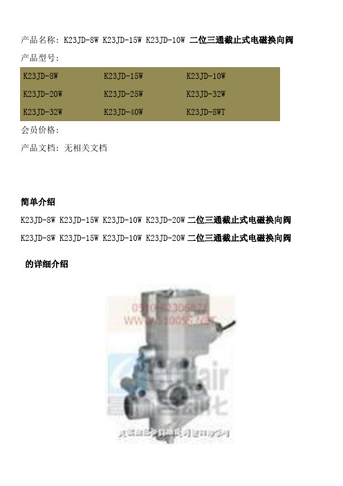
二位三通截止式电磁换向阀,K23JD-8W,K23JD-15W,K23JD-10W,K23JD-20W,二位三通截止式电磁换向阀价格
K23JD-8W
K23JD-10W
K23JDБайду номын сангаас15W
K23JD-20W
K23JD-25W
K23JD-32W
K23JD-40W
K23JD-50W
介质温度和环境温度(℃)
-5-50
工作压力范围(MPa)
0.2-0.8
换向时间(sec)
≤0.04
≤0.06
≤0.10
最高切换频率(Hz)
≥10
≥8
K23JD-8WK23JD-15WK23JD-10WK23JD-20W二位三通截止式电磁换向阀
的详细介绍
二位三通截止式电磁换向阀
无锡截止式换向阀生产厂家价格
产品特点
K23JK-W系列是二位三通单气控管接截止式换向阀。该阀结构合理,动作可靠,维修方便,尤其适用于较为恶劣的工作环境。分电控和气控两种。
图形符号:
≥4
有效截面积S值(mm²)
10
20
35
60
120
190
工作电压(V)
AC:380,220,110,36;DC:220,110,24
相关产品
K23JD2-6 K23JD2-8 K23JD2-10 K23JD2-15二位三通换向阀K23JD2-6 K23JD2-8 K23JD2-10K23JD2-15
K23JK-6 K23JK-6 K23JK-8 K23JK-8W二位三通换向阀K23JK-6 K23JK-6 K23JK-8 K23JK-8W
K23JK-10 K23JK-10W K23JK-15 K23JK-15W二位三通换向阀K23JK-10 K23JK-10W K23JK-15 K23JK-15W
VN8 系列电动二通阀 三通阀 安装说明说明书

1安装说明-----2019-VN8系列电动二通阀/三通阀技术参数执行器部分工 作 电 源: 220Vac ±10%,110Vac ±10% 24Vac ±10% 50/60Hz控 制 方 式: 开关式(三线两控),非弹簧复位功能 工作环境温度: 0 ~ 65℃工作相对湿度: 10% ~ 90%RH 无冷凝水 功 率: ≤6W(50Hz);≤7.5W(60Hz) 动 作 时 间: 开启≤15s ,关闭:≤15s 防 护 等 级: IP42 阀体部分适 用 介 质: 冷、热水或50%乙二醇溶液 介 质 温 度: 0 ~ 94℃ 工作环境温度: 0 ~ 65℃ 工作相对湿度: 10% ~ 90%RH运输储存温度: - 40 ~ 65℃,10% ~ 90%RH 无冷凝水 公 称 压 力: PN20材 质: 阀体和球体 — 锻造黄铜 (HPb59-1) 阀 杆 — 不锈钢 (0Cr18Ni9) 阀 座 — 聚四氟乙烯 (PTFE) O 形密封圈 — 三元乙丙橡胶 (EPDM)命名规则 接线图2霍尼韦尔环境自控产品(天津)有限公司 天津经济技术开发区南海路158号 邮编:300457电话:+86-22-66287000传真:+86-22-25325214说明书如有变动,不另行通知。
-----2019-∙ 产品可以安装在竖直或水平管道上。
∙ 在竖直管道上,产品可以任意位置安装。
∙ 在水平管道上,执行器必须与管道中心线齐平或高于中心线。
∙ 确保在执行器上面留下足够的空间,以便拆卸维修。
∙ 为防止阀体破裂或接套松动,安装或拆卸时需使用板钳或板手在球体的同一侧操作,如右图所示。
∙ VN8系列电动阀是为全封闭式系统设计。
不建议在开式系统使用。
在开式系统里,过多的氧气及氯气溶解会侵蚀阀体材料,形成过早的损坏。
安装注意事项外观尺寸3INSTALLATION MANUAL-----2019-VN8 Series 2-way/3-way FCU ControlValvesProduct Identification System TechnicalActuators:Operation voltage: 220Vac±10%, 110Vac±10% 24Vac±10% 50/60HzControl mode: ON /OFF type (Three wire twocontrol ),Non -Spring returnOperating temperature: 0 ~ 65°COperating relative humidity: 10% ~ 90%RH, no condensating Power: ≤6W(50Hz);≤7.5W(60Hz) Operating time: Open ≤15s Close ≤15s Protection rating: IP42Valves:Applicable medium: Cold or hot water, up to 50% glycol Medium temperature : 0 ~ 94°C Operating temperature: 0 ~ 65°COperating relative humidity: 10% ~ 90%RHStorage conditions: -40 ~ 65°C, 10% ~ 90%RH, no condensating Nominal pressure: PN20Materials: Valve body or ball - Forged brass(HPb59-1 ) Valve stem - Stainless steel(0Cr18Ni9 )Ball Sealing - Poly tetrae fluoro ethylene(PTFE) O -ring seal - EPDMWiring4Honeywell Environmental & Combustion Controls (Tianjin) Co.,Ltd.No. 158, NanHai RoadTianjin Economic -Technological Development Area Tianjin, 300457, P.R.C. Phone: +86-22-66287000Fax: +86-22-25325214Subject to change without notice.Dimensions (mm)-----2019- Installation Guide∙ The FCU valve can be mounted in any position on a vertical line .∙ If the valve is mounted horizontally, the powerhead must be even with or above the center line of the piping .∙ Make sure to leave enough room above the powerhead to remove the cover for servicing . ∙ To avoid valve breaking or unscrew the end pieces, please operate the spanners on the same side of the valve body during the installation (as the figure on the right) .∙VN8 Series valves are designed for the application to closed system. Use in open system is not recommended. High levels of dissolved oxygen and chlorine round in open systems may erode the valve material and result in premature failure.。
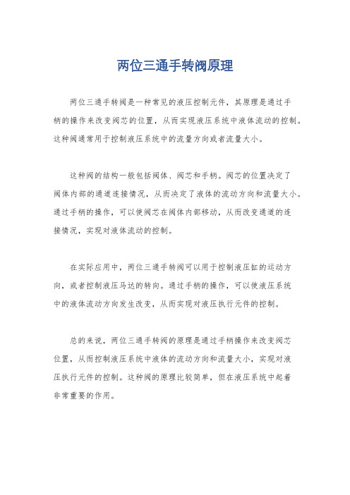
两位三通手转阀原理
两位三通手转阀原理
两位三通手转阀是一种常见的液压控制元件,其原理是通过手
柄的操作来改变阀芯的位置,从而实现液压系统中液体流动的控制。
这种阀通常用于控制液压系统中的流量方向或者流量大小。
这种阀的结构一般包括阀体、阀芯和手柄。
阀芯的位置决定了
阀体内部的通道连接情况,从而决定了液体的流动方向和流量大小。
通过手柄的操作,可以使阀芯在阀体内部移动,从而改变通道的连
接情况,实现对液体流动的控制。
在实际应用中,两位三通手转阀可以用于控制液压缸的运动方向,或者控制液压马达的转向。
通过手柄的操作,可以使液压系统
中的液体流动方向发生改变,从而实现对液压执行元件的控制。
总的来说,两位三通手转阀的原理是通过手柄操作来改变阀芯
位置,从而控制液压系统中液体的流动方向和流量大小,实现对液
压执行元件的控制。
这种阀的原理比较简单,但在液压系统中起着
非常重要的作用。
电控三通调节阀说明书
电控三通调节阀产品说明书V2.2江苏氢港新能源科技有限公司修订记录版本号日期修订者内容说明V1.02020.8.13初版V1.12020.9.25修正部分内容V1.22020.10.25修正部分内容V1.32021.02.09修订部分内容V2.02021.02.23变更ECV-0350B尺寸V2.12021.05.08增添部分内容V2.22021.06.08CAN协议内容增加江苏氢港新能源科技有限公司为客户提供7×24小时全方位的技术支持和服务,公司设有专业的技术支持团队,提供售前、售后的技术咨询、产品维修技术服务,用户可直接与客户中心联系。
江苏氢港新能源科技有限公司地址:江苏省张家港市中兴路180号网址:Email:**********************客户热线:(00)86-0512-********本说明书涉及电控三通阀的安装和使用。
适用于对电控三通阀进行安装、操作、维护的专业技术人员和日常操作的人员。
读者需具备一定的电子电气、控制、机械等知识。
为确保个人和财产安全或有效使用本产品,请在安装和使用前仔细阅读本说明书。
江苏氢港新能源科技有限公司对本说明书保留一切权力,内容如有变动,恕不另行通知。
目录1.产品特点 (6)2.选型说明 (7)3.技术参数 (7)4.阀旋转角度与开度的关系 (8)5.压力损失曲线 (8)6.尺寸 (9)7.接口说明 (10)7.1流体接口 (10)7.2电气接口定义 (11)8.安装及应用 (12)9.通信控制 (12)10.故障与处理 (13)1.产品特点本产品是一款智能型电动控制调节阀,阀集成驱动控制器,CAN总线控制,兼容汽车总线,使用方便角度实时控制和反馈宽电压范围,兼容乘用车、商用车流体接触部件无金属材料、无腐蚀、无离子析出,不影响液体绝缘性低流阻2.选型说明注:其他特殊要求,请联系公司技术人员确认。
3.技术参数型号ECV-0338B ECV-0350B工作电压DC12V/24V(9-32V)工作电流0.4A@24V全行程角度范围0~90°有效行程角度范围10~80°全行程时间约3s控制方式默认CAN2.0B,波特率250K程序刷写基于CAN的BootloaderIP等级IP67工作介质纯水或水-乙二醇冷却液介质温度-40~95℃工作环境温度-40~85℃最大工作压力3bar,g内泄漏量≤50mL/min@ΔP=1bar进/出接口OD38.4mm墩头OD50.8mm墩头重量约1.0kg约1.2kg4.阀旋转角度与开度的关系5.压力损失曲线(测试介质:25℃,纯水)6.尺寸型号:ECV-0338B型号:ECV-0350B(版本V2)7.接口说明7.1流体接口出厂初始状态设为0°,即口2全开、口3全关。
电动三通调节阀原理
电动三通调节阀原理
电动三通调节阀是一种使用电动装置控制阀门开关以实现流体流量和流向调节的装置。
它由电动执行机构、阀体和调节机构组成。
电动执行机构是整个调节阀的核心部件,一般采用电动机、传动装置和反馈装置组成。
其中,电动机通过传动装置转动阀杆或阀盘,实现阀门的开启和关闭。
反馈装置反馈阀门的位置信息给控制系统,以实现对阀门位置的监测和控制。
阀体是阀门的主要组成部分,它由阀门座、阀芯和阀座组成。
阀芯上有孔道,通过改变阀芯在阀座上的位置,来调节介质的流量和流向。
阀芯运动的过程中,液体会从输入口进入阀体,经过阀芯和阀座的相应孔道后,流出阀体的输出口。
调节机构主要用来调节阀门的开度,以控制流体的流量和流向。
调节机构一般由开度调节装置和反馈装置组成。
开度调节装置通过改变阀门的开度,来改变阀门的流量特性,以达到控制介质流量的目的。
反馈装置用来监测阀门的位置信息,并将其反馈给控制系统,以实现对阀门位置的精确控制。
总的来说,电动三通调节阀通过电动执行机构驱动阀门的开关,通过阀体的孔道调节介质的流量和流向,通过调节机构控制阀门的开度,实现对介质流量和流向的精确调节。
基于广义预测控制的泵控马达调速系统的研究
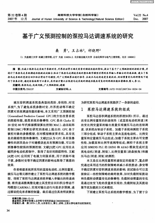
2 世纪 8 年代根据模型算法控制( A )动态矩阵 0 0 M C、 控制 ( M ) D C 等算法研究 的基础上提 出的. P G C基 于 被控对象的参数模型 , 但对模 型精度要求低 , 具有优 良的跟 踪 性 能 和鲁 棒 性 . 献 【] 为 G C具 有 强鲁 文 2认 P
棒性 的原 因是 由于对建 模误 差具 有预测 功 能 , 以得 可
性轮 、 加载泵和比例节流阀等组成 ; 测控子系统主要 应用 SM N L I E S C的 D/ O和 A/O模块完 成对直 P I D I A 流电动机( 转速 、 转矩 )比例变量泵( 、 斜盘倾 角) 和液 压马达 ( 转速 、 转矩 ) 的测控 .
本 文是 在 比例变 量 泵转 速恒 定 的前 提下 。 点研 重
维普资讯
第 2 卷第 4 2 期 湖南科技大学学报( 自然科学版 ) 20 0 7年 1 月 Ju a o H n nU i rt o S i c 2 o r l f u a n esy f c ne&T c n l yN tr c ne E i n n v i e eh o g ( au l i c di ) o aSe t o
下面建立泵控马达系统的数学模型 , 为了便于分
作者简介 : 勇 (99 )男 , 桑 17一 , 山东泰安人 , , 博士 讲师, 主要从事电液传动控制研究.
维普资讯
析数学模型只考虑高压管路压力的变化 , 且忽略高压 管路压力的瞬间突变引起减压阀对系统性能的影响,
行 了仿真分析 , 通过仿真结果可以看 出, 采用该方案以后 泵控马达 系 统的调 速性 能具有 良 的跟踪性能和鲁棒性阁 4参 l. 好 , O
关键词 : 泵控马达 ; 电液伺服 ; 广义预测控制; 建模 中图分类号 : H17 T 3 文献标识码 : A 文章编号 :6 2 90 (0 70 - 0 4 0 17 - 12 20 )4 03 - 4
电动三通调节阀的结构特点

电动三通调节阀的结构特点电动三通调节阀是一种通过电动机驱动的阀门,用于控制管道中流体的流量、压力和温度。
它的结构特点主要体现在以下几个方面:1. 阀体结构:电动三通调节阀的阀体通常采用球形或圆柱形,具有较高的密封性能和耐磨性。
阀体内部设置有阀座和阀芯,通过阀芯的开闭来控制流体的通断。
2. 电动驱动装置:电动三通调节阀的核心部件是电动驱动装置,它由电动机、减速机和执行器组成。
电动驱动装置通过转动阀芯实现对流体的调节。
通常情况下,电动驱动装置可以根据控制信号的输入,自动控制阀芯的开度,从而实现对流体流量的控制。
3. 控制系统:电动三通调节阀通常配备有先进的控制系统,用于接收控制信号并驱动电动驱动装置。
控制系统可以根据实际需要,调整阀芯的开度,从而实现对流体的精确控制。
同时,控制系统还可以进行故障诊断和报警,提高设备的可靠性和安全性。
4. 密封结构:电动三通调节阀的密封结构是其重要的结构特点之一。
阀芯与阀座之间采用可靠的密封结构,确保阀门在关闭状态下具有良好的密封性能。
同时,阀芯的密封结构还可以根据需要进行调整,以满足不同工况下的使用要求。
5. 阀芯结构:电动三通调节阀的阀芯通常采用直通式或倾斜式结构。
直通式阀芯可以实现较大的流量调节范围,适用于大口径的阀门。
倾斜式阀芯则可以实现较小的流量调节范围,适用于小口径的阀门。
6. 材料选择:电动三通调节阀的材料选择要考虑到流体的性质和工作环境的要求。
阀体和阀芯通常采用耐腐蚀、耐高温的材料,如不锈钢、铸钢等。
密封材料通常采用耐磨损、耐高温的材料,如聚四氟乙烯、聚酰亚胺等。
电动三通调节阀具有结构简单、控制精度高、可靠性好等特点,广泛应用于工业生产中的流体控制系统中。
通过对阀体结构、电动驱动装置、控制系统、密封结构、阀芯结构和材料选择的优化,可以进一步提高电动三通调节阀的性能和可靠性,满足不同工况下的使用需求。
两位三通电磁阀工作原理

两位三通电磁阀工作原理
电磁阀是以电磁力为驱动力控制工作机构(如阀体)的阀门,实现对流体的控制。
电磁阀一般由电磁操纵部分和主阀部分组成。
工作原理:
1. 电磁操纵部分:操纵部分包括线圈和可动铁芯。
当通过线圈通电时,线圈内产生电磁场,使得铁芯受到磁力作用,下压或上升。
2. 主阀部分:主阀部分包括阀体、阀芯和密封垫等。
阀体内设有控制流体流动的通道,阀芯与阀体之间通过密封垫进行密封。
阀芯的上端与可动铁芯连接。
工作过程:
1. 开启状态:当线圈通电时,线圈内产生电磁场,使得可动铁芯被吸引,并将阀芯顶开,打开阀芯与阀体之间的通道,使流体能够通过。
2. 关闭状态:当线圈断电时,电磁场消失,可动铁芯失去磁力作用,弹簧的作用下,阀芯被弹回,关闭阀芯与阀体之间的通道,阻止流体通过。
通过控制线圈的通电和断电,能够实现电磁阀的开闭,并对流体进行控制。
液压控制系统汪首坤第四章作业
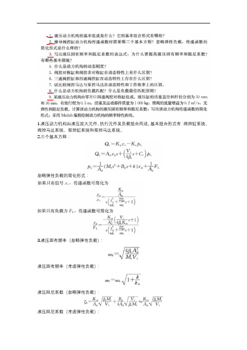
1.液压动力机构由液压放大元件、执行元件及负载组合而成。
基本组合形式有:阀控缸系统、阀控马达系统、泵控缸系统和泵控马达系统。
2.三个基本方程:忽略弹性负载的简化形式:3.液压固有频率(忽略弹性负载):液压固有频率(考虑弹性负载):液压阻尼系数(忽略弹性负载):液压阻尼系数(考虑弹性负载):液压固有频率表示液压执行元件动态响应的快速性,固有频率越高,响应速度越快;液压阻尼系数直接影响系统的稳定性,而液压系统本身是低阻尼的,因此提高液压阻尼系数是保证液压系统稳定性的重要措施。
提高液压固有频率的方法:增加活塞有效面积,减小总容腔体积,减小运动部件质量,提高等效弹性模量。
提高液压阻尼系数的方法:采用正开口阀,加大阀预开口量,提高压力-流量系数;采用旁路泄露的方式,加大泄露系数;增大负载阻尼系数。
4. 动力机构的负载匹配问题讨论动力机构的输出速度和输出力是否满足负载速度和负载力的需要,负载匹配要通过负载轨迹与动力机构的输出特性的比较来确定。
负载最佳匹配原则:动力机构的输出特性不仅满足最大负载要求,并且实现了负载轨迹的最小包络(在最大功率点相切)。
9.等效体积弹性模量βe 取6.9*108N/m 2,液压缸两腔的总容积V t ,活塞及由负载折算至活塞上的总质量M t 取1000kg ,活塞有效面积A p ,总压力流量系数K ce =K c +C t ,K c 为压力流量系数,C t 为总泄露系数,C t =C i +C e /2,C i 为内泄露系数,C e 为外泄露系数,K ce 取7.6∗10−12,流量增益系数K q 为0.2m 3/s 。
ωℎ=√4βe A p 2M t V t =√4∗6.9∗108∗(π∗(0.0252−0.0182))21000∗(π∗(0.0252−0.0182)∗0.5)=72.2 rad/s ξℎ≈K ce A p √βe M t V t =7.6∗10−12π∗(0.0252−0.0182)√ 6.9∗108∗1000π∗(0.0252−0.0182)∗0.5=0.31 G(s)=K qA p 1s(s 2ωℎ2+2ξℎωℎs +1)=211.50.0002s 3+0.0086s 2+s。
G820系列电动三通调节阀
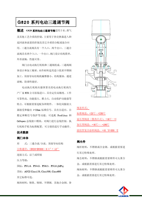
概述 G820系列电动三通调节阀适用于水,蒸气及其他工艺介质的控制,主要用于热交换器进入和返回流体流量的控制及其它介质的分配或混合应用。
三通分流阀具有一个入口,两个出口。
三通合流阀具有两个入口,一个出口。
阀门设计结构简单,外形流畅,性能可靠。
阀门由电动执行机构和三通阀组成。
三通阀阀体设计和加工精密,内件材料选用进口优质不锈钢加工,顶部导向结构机械摩擦小,结构紧凑,通道流畅,防堵性能好。
电动执行机构从德国著名的电动执行机构生产厂家RTK 公司原装进口。
具有定位高精度、工作可靠性高、功能强大、推力大,自动保护功能强等特点。
可根据需要选配各种附件。
一体化伺服放大器接受和输出4-20mA 标准信号,具有自适应,自整定和断信号保护等功能。
可选配Profibus 和CANopen 总线接口模块,对阀门进行总线控制。
执行机构手轮为标准配置,可方便的进行手动操作。
技术数据 阀门本体形 式:三通合流/分流,顶部导向结构 公称通径:(DN20-DN300)3/4”- 12” 连接方式:法兰或焊接 压力等级:国标:PN1.6,PN4.0,PN6.3,PN10 (MPa) 美标:ANSI Class150, Class300, Class600 其它标准可选。
阀体材料:铸铁、铸钢、不锈钢, 其他合金钢,参阀盖形式:标准阀盖:-28℃—+250℃延长型阀盖(散热片式):-46℃—+550℃ 加长型阀盖:-46℃— -196℃ 波纹管复合添料阀盖:-40‘C-350‘C阀内件阀杆材料:不锈钢或合金钢,或根据需要进行其它特殊处理。
阀芯材料:不锈钢或根据需要堆焊司太莱合金,或根据需要进行其它特殊处理。
阀座材料:不锈钢或根据需要堆焊司太莱合金,或根据需要进行其它特殊处理。
阅附表。
阀杆密封:聚四氟乙烯、石墨、波纹管电动执行机构控制模式:三步式控制(开关),连续控制(调节),总线控制。
执行机构输出力:3 / 6 / 10 / 15 KN电机保护:采用自锁和防停转电机,或使用力矩和限位开关,无须过热保护开关。
电动三通工作原理
电动三通工作原理
电动三通是一种常用的控制阀门,其工作原理如下:
1. 电动三通由电动执行器和阀体组成。
电动执行器通常由电机,减速器和行程传感器组成,它们的作用是控制阀盘的运动。
2. 当电动执行器接收到信号时,电机开始运转。
减速器通过减速作用将电机的高速旋转转化为阀盘的低速旋转。
3. 阀体内部的阀盘通过电动执行器的控制而旋转,从而改变阀体内的流道连接。
4. 当阀盘处于一个位置时,阀体的入口与一个通道连接,而出口与另一个通道连接。
这种状态下,介质可以从一个通道流过阀体到达另一个通道,实现三通的控制。
5. 当阀盘旋转到另一个位置时,入口与一个通道连接,而出口则与另一个通道连接。
这时介质的流动路径发生变化,实现了另一种三通的控制。
综上所述,通过控制电动执行器的运动,电动三通能够实现不同的阀体内部流道连接方式的改变,从而达到控制介质流动的目的。
液压控制系统基础知识总结考试复习资料
1、液压控制系统组成部分:指令元件,比较元件,反馈测量元件,放大转换元件,执行元件,被控对象,能源装置与其他校正装置2、液压控制系统工作的基本原理:以液压速度控制系统为例说明,当指令电位器给出一个指令信号时,通过比较器与反馈信号比较,输出偏差信号Δu,偏差信号经伺服放大器输出控制电流i,控制电液伺服阀运动,伺服阀输出流量、压力来控制液压伺服缸,推动工作台运动。
4、液压控制系统的能量传递效率,是高还是低?(低)变量泵0.667;定量泵+溢流阀0.3855、液压控制系统的主要特点:优点:体积小,重量轻,控制精度高,响应速度快,抗负载刚度大;此外,液压系统润滑性好,寿命长,调速范围宽,低速稳定性好,过载保护容易等。
缺点:液压元件抗污染能力差,油温变化对系统影响大,元件易泄露,引起污染;元件精度高,成本高,远距离传输不如电气系统方便。
1、液压控制阀在液压控制系统中的作用是什么?信号转换,功率放大,伺服控制3、正开口四通滑阀,与零开口阀相比较,在零位时各个阀系数有何不同之处?与零开口四通阀阀系数比较:正开口阀流量增益大一倍,正开口阀稳态特性曲线线性度好,正开口阀泄漏量大。
4、零开口四通滑阀,当处于零位工作时,各个阀系数(流量增益、压力增益、流量压力系数)以与阻尼比处于最大值还是最小值?零位工况点,是工况最好的点还是最差的点?(最差)流量增益最大,流量-压力系数最小,压力增益最高,系统阻尼比最小。
5、圆柱滑阀的边、通的概念是什么?从控制性能看,哪种圆柱滑阀最好,哪种最差?根据圆柱滑阀控制边(节流菱边)的数目不同,可分为单边、双边和四边滑阀。
从加工性能来看,单边阀加工工艺最简单,四边阀加工工艺最难。
从控制性能来看,四边阀最好,单边阀最差。
边:参与对油液流动控制的边:通:与外界的通道。
6、按反馈形式的不同,两级电液伺服阀中有位置反馈、负载压力反馈和负载流量反馈三种。
7、零开口四通阀,零位阀系数的计算公式:,,8、作用在阀芯上的液动力分为分为稳态液动力和瞬态液动力。
二位三通阀工作原理
二位三通阀工作原理二位三通阀是一种常见的控制阀,广泛应用于工业领域的流体控制系统中。
它的工作原理十分重要,对于了解阀门的运行机制和控制流体的过程有着至关重要的作用。
下面我们就来详细探讨一下二位三通阀的工作原理。
首先,我们需要了解二位三通阀的结构。
二位三通阀由阀体、阀盖、阀芯、阀座、执行机构等部件组成。
阀芯是控制流体通道的关键部件,它的位置决定了流体的通路。
执行机构则是用来控制阀芯位置的,通过执行机构的动作,可以改变阀芯的位置,从而实现对流体通路的控制。
在工作时,当执行机构作用于阀芯时,阀芯就会移动,改变流体的通路。
当阀芯处于一种位置时,流体就会按照相应的通路流动,当阀芯移动到另一种位置时,流体的通路也会相应地改变。
这样,通过控制阀芯的位置,就可以实现对流体的控制。
二位三通阀的工作原理可以分为两种工作方式,正常工作方式和反向工作方式。
在正常工作方式下,阀芯的位置决定了流体的通路,执行机构作用于阀芯时,流体就会按照设定的通路流动。
而在反向工作方式下,阀芯的位置与正常工作方式相反,执行机构作用于阀芯时,流体的通路也会相应地改变。
通过这两种工作方式,可以实现对流体的正向和反向控制。
除了正常工作方式和反向工作方式外,二位三通阀还可以通过控制阀芯的位置来实现对流体的调节。
通过改变阀芯的位置,可以改变流体通路的大小,从而实现对流体流量的调节。
这样,二位三通阀不仅可以控制流体的通路,还可以实现对流体流量的调节。
总的来说,二位三通阀通过控制阀芯的位置,实现对流体通路的控制和调节。
它的工作原理十分简单明了,但却十分重要,对于工业领域的流体控制有着不可替代的作用。
希望通过本文的介绍,能够对二位三通阀的工作原理有一个更加深入的了解。
液压马达伺服系统

串联阀控液压马达速度伺服系统
文档仅供参考,如有不当之处,请联系改正。
(四)阀控液压马达速度伺服系统
节流式并联阀控液压马达速度伺服系统
文档仅供参考,如有不当之处,请联系改正。
(四)阀控液压马达速度伺服系统
补油式并联阀控液压马达速度伺服系统
文档仅供参考,如有不当之处,请联系改正。
(五)阀泵串联控制液压马达速度调整系统
文档仅供参考,如有不当之处,请联系改正。
(六)液压马达速度伺服系统构造与性能比较
与开环速度控制系统相比,它增长了一种主反馈通道 和一种积分放大器,构成了Ⅰ型系统,所以其精度远比 开环系统为高。缺陷是系统构成较复杂,成本高,设计 难度大。
文档仅供参考,如有不当之处,请联系改正。
(三)不带位置环旳泵控闭环速度控制系统
ei
信号 发生
比较 eg
ef
百分比 放大器
伺
液
变
服
压
量
阀
缸
泵
m 液压 马达
测速发电机
泵控闭环速度控制系统构成原理框图 1)变量伺服机构旳液压缸本身具有积分环节,系统型式不变(相 对型式(二)而言) 2)积分环节在背面,伺服阀零漂和斜盘力等引起旳静差依然存在 3)变量机构开环控制,抗干扰能力差,易受零漂、摩擦等影响
文档仅供参考,如有不当之处,请联系改正。
(四)阀控液压马达速度伺服系统
阀控非对称液压缸数学模型及建模方法研究

MECHANICAL ENGINEER阀控非对称液压缸数学模型及建模方法研究炘李晓园,陈,叶鹏,李鑫,徐祥,蒋辉,李琼柱(红塔烟草(集团)有限责任公司玉溪卷烟厂,云南玉溪653100)摘要:非对称液压缸两腔结构参数不同,给阀控非对称缸数学建模带来了较大的困难。
文中针对现行阀控非对称液压缸数学模型及简化方法作了分析比较,提出了一种新的简化方法,并据此导出了较为精确的数学模型。
关键词:非对称液压缸;数学模型;建模方法;辅助方程中图分类号:TH137文献标志码:A文章编号:1002-2333(2020)08-0104-04 Research on Mathematical Model and Modeling Method of Valve Controlled Asymmetric Hydraulic Cylinder LI Xiaoyuan,CHEN Xin,YE Peng,LI Xin,XU Xiang,JIANG Hui,LI Qiongzhu (The Second Workshop of Cigarette Packaging of Yuxi Cigarette Factory,Hongta Tobacco(group)Co.,Ltd.,Yuxi653100,China) Abstract:The structural parameters of the two chambers of the asymmetric hydraulic cylinder are different,which brings great difficulties to the mathematical modeling of the valve-controlled asymmetric cylinder.This paper analyzes and compares the current mathematical models and simplified methods of valve-controlled asymmetric hydraulic cylinders, proposes a new simplified method,and derives a more accurate mathematical model based on this.Keywords:asymmetric hydraulic cylinder;mathematical model;modeling method;auxiliary equation0引言液压控制系统的种类及分类方法很多,根据液压放大器与执行元件的不同组合,可分成阀控缸、阀控马达、泵控缸、泵控马达4种[1-2],其中阀控缸响应快、精度高、应用最广。
水管电动三通调节阀的作用
水管电动三通调节阀的作用随着科技的不断发展,各行各业都在不断寻求更高效、更智能的解决方案。
在工业和民用领域中,水管系统的自动化调节已经成为一种趋势。
而水管电动三通调节阀作为其中的重要组成部分,其作用和意义也越来越受到重视。
一、水管电动三通调节阀的基本概念。
水管电动三通调节阀是一种能够通过电动执行机构来控制流体介质流动方向和流量的阀门。
它通常由阀体、阀盖、阀芯、执行机构等部件组成。
通过控制执行机构的开合和旋转,可以实现对流体介质的调节和控制。
二、水管电动三通调节阀的作用。
1. 流体介质的分流和合流,水管电动三通调节阀可以根据需要调节流体介质的分流和合流比例,实现不同管道之间的流体调节和控制。
2. 流量的调节和控制,通过调节阀门的开度和旋转角度,可以精确地控制流体介质的流量,满足不同工艺和设备对流量的要求。
3. 流体介质的转向和分配,水管电动三通调节阀可以实现流体介质的转向和分配,使得流体在管道系统中能够按照设计要求进行流动和分配。
4. 系统的自动化控制,水管电动三通调节阀可以与控制系统进行联动,实现对整个水管系统的自动化控制,提高系统的稳定性和效率。
5. 节能和环保,通过精确的流量控制和流体介质分配,可以减少系统中的能耗和资源消耗,达到节能和环保的目的。
三、水管电动三通调节阀的应用领域。
1. 工业领域,水管电动三通调节阀广泛应用于化工、石油、冶金、电力等工业领域,用于控制各种介质的流动和分配。
2. 水利领域,在水利工程中,水管电动三通调节阀用于控制水流的分配和调节,保障水利工程的安全和稳定运行。
3. 水处理领域,在水处理系统中,水管电动三通调节阀用于控制各种介质的流动和分配,保证水处理设备的正常运行。
4. 暖通空调领域,在暖通空调系统中,水管电动三通调节阀用于控制冷热水的流动和分配,实现暖通空调系统的自动化控制。
5. 建筑领域,在建筑系统中,水管电动三通调节阀用于控制供暖、供水、排水等系统的流动和分配,提高建筑系统的舒适性和节能性。
导热油三通调节阀工作原理
导热油三通调节阀工作原理导热油三通调节阀是一种常用于工业生产中的阀门设备,主要用于控制导热油在系统中的流动和温度。
它通过调节阀门的开合程度,来控制导热油的流速和流向,从而实现对系统运行温度的调节和控制。
导热油三通调节阀的工作原理涉及到流体动力学、热传导等多个领域的知识,下面将对其工作原理进行详细的探讨。
首先,导热油三通调节阀的结构包括阀体、阀芯、驱动装置等部件。
其中,阀体是导热油流动的通道,阀芯则是控制导热油流向的关键部件。
当驱动装置施加力量使阀芯移动时,导热油的流动方向和流速就会发生变化,从而实现对系统温度的调节。
此外,导热油三通调节阀还配有传感器和反馈控制系统,通过监测系统温度和压力等参数,实现自动控制和调节。
导热油三通调节阀的工作原理主要涉及到两个方面,即导热油流动特性和热传导特性。
在导热油流动特性方面,当阀芯向开启的方向移动时,导热油的流速会逐渐增大,从而增加系统的换热效率。
反之,当阀芯向关闭的方向移动时,导热油的流速会减小,使系统温度逐渐降低。
通过不断调节阀芯的位置,可以实现系统温度的精确控制。
另一方面,导热油三通调节阀还利用了热传导特性来实现对系统温度的调节。
导热油在流动过程中会吸收热量,并将热量传递到系统中的其他部件。
当阀芯调节到合适的位置时,导热油的传热效率会达到最优值,从而保持系统的稳定温度。
通过调节阀芯的位置,可以实现系统温度的精确控制,提高系统的运行效率。
总的来说,导热油三通调节阀是一种非常重要的工业阀门设备,它通过控制导热油的流速和流向,实现对系统温度的调节和控制。
其工作原理涉及到导热油的流动特性和热传导特性,通过不断调节阀芯的位置,可以实现系统温度的精确控制,提高系统的运行效率。
在未来的工业生产中,导热油三通调节阀将继续发挥重要作用,为各种工艺系统提供稳定可靠的温度调节服务。
新型电源车液压系统调速特性研究
.
Q A P d ( r, = 鲁 LIP 3 + L ) I ,
补油泵用作液压系统冷却、 散热和补充泄漏等 , 并为 变量机构提供恒定的控制压力。
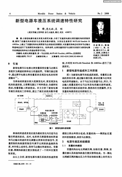
图 1 新型电源车原理 图
柴油机转速或者是后接负载的变化均引起马达 输 出转速的波动。此时, 电控单元 根据柴油机转速 和马达输出转速的变化调整 比例泵 的控制信号, 变
模型主要由两部分组成: 变量机构——阀控缸位 置 闭环控制模型 ; 泵控马达模型。
量控制机构根据 控制信号调节 比例泵斜盘倾斜角 度 , 补偿上 述变化 , 来 保持 马达输 出转速 恒定 。变 量 柱塞 、 滑阀和斜盘位置反馈组成 了一个闭环位置控
制 系统 。
2 电源车液压 系统模型
2 1 变量机 构模型 .
变量机构由电比例减压阀、 初级柱塞、 滑阀、 变
可 以表 示 为 :
= ห้องสมุดไป่ตู้
cP ・ ( lI 鲁 7  ̄+
式中 D ——马达排量 ∞ — — 马达角 速度 ;
C ——泵和马达总泄漏系数 ;
— —
先导级 , 其本质上可以简化成一个 比例环节。即有 :
X = ・ ,一,. n ( m) m () 1
高压腔 容积 ( 量泵 油液 出 口处 容 变 积、 油管 容 积 和 马达 油 液 人 口处 容 积
O 引 言
新型电源车以电液比例变量泵控定量马达液压 系统作为调速机构和动力传递纽带。车辆行驶过程 中, 通过调节电液 比例变量泵来实现发电机的恒转 速输 出… 。 当柴油机转速在较大范围变化 时, 要实现发电 机 的恒 速控制 , 主要需 克服 以下两种 扰动 : 负载转矩 扰动 ; 变量泵输入转速扰动。本文分析了新型电源 车液压系统的工作特性, 建立 了液压系统 的数学模
导热油三通调节阀工作原理
导热油三通调节阀工作原理
导热油三通调节阀是一种用于导热油循环系统的控制元件,主要作用是调节导热油的流量和温度,以保证系统的稳定运行。
该调节阀是通过改变导热油的流向来实现对系统温度的控制的。
导热油三通调节阀通常由三通阀体、阀芯、执行器和控制系统组成。
其工作原理如下:
1. 正常工作状态下,导热油从系统中流出经过三通阀体,进入到调节阀中。
在调节阀中,导热油可以选择流向不同的出口。
2. 当控制系统感知到系统温度低于设定值时,控制系统会发送信号给执行器,执行器接收到信号后会调节阀芯的位置,使导热油流向受热设备,从而提高系统温度。
3. 当系统温度高于设定值时,控制系统会再次发送信号给执行器,执行器接收到信号后会调节阀芯的位置,使导热油流向冷却设备,降低系统温度。
4. 调节阀芯的位置由执行器控制,可以根据系统需求随时调整,以确保系统的温度稳定在设定值附近。
通过以上工作原理,导热油三通调节阀可以实现对系统温度的精确控制,确保系统在正常工作范围内运行稳定。
同时,该调节阀还可以提高系统的运行效率,延长设备的使用寿命,是导热油循环系统中至关重要的一环。
西门子2-3通电磁阀40毫米行程电液伺服执行器SKC32... SKC82... SKC62...
4564Electro-hydraulic actuators for valveswith a 40 mm stroke SKC32... SKC82... SKC62…SKC60•SKC32... Operating voltage AC 230 V, 3-position control signal•SKC82... Operating voltage AC 24 V, 3-position control signal•SKC6... Operating voltage AC 24 V, control signal DC 0…10 V, 4…20 mA or0...1000 Ω•SKC6… Choice of flow characteristic, position feedback, stroke calibration,LED status indication, override control•SKC62UA with functions choice of direction of operation, stroke limit control,sequence control with adjustable start point and operating range,operation of frost protection monitors QAF21... and QAF61...•Positioning force 2800 N•Actuator versions with or without spring-return function•For direct mounting on valves; no adjustments required•Manual adjuster and position indicator•Optional functions with auxiliary switches, potentiometer, stem heater andmechanical stroke inverter•SKC...U are UL-approvedUseFor the operation of Siemens 2-port and 3-port valves, types VVF... and VXF... with a40 mm stroke as control and safety shut-off valves in heating, ventilation and airconditioning systems.CM1N4564ESiemens Building Technologies2/16Types Spring-return Positioning timeTypeOperating voltagePositioning signal Function Time Opening Closing Enhanced functionsSKC32.60SKC32.61 AC 230 Vyes 18 s SKC82.60 SKC82.60U *SKC82.61 SKC82.61U *3-positionyes 18 s 120 sSKC62 SKC62U * yes 20 s Standard electronicsSKC60Enhanced electronicsSKC62UA *AC 24 VDC 0...10 V,4...20 mA,or 0...1000 Ωyes 20 s120 s20 syes 1)1)Direction of operation, stroke limit control, sequence control, signal addition *UL-approved versionsTypeDescription For actuator Mounting location ASC1.6 Auxiliary switchSKC6… ASC9.3 Dual auxiliary switches ASZ7.3Potentiometer 1000 Ω ASZ7.31 Potentiometer 135 Ω ASZ7.32 Potentiometer 200 Ω SKC32… SKC82… 1 x ASC 1.6 or 1 x ASC9.3 or 1 x ASZ7.3 or 1 x ASZ7.31 or 1 x ASZ7.32 ASZ6.5 Stem heater AC 24 VSKC…1 x ASZ6.5When ordering please specify the quantity, product name and type code. Example: 1 actuator, type SKC32.60 and 1 potentiometer, 135 Ω, type ASZ7.31The actuator, valve and accessories are supplied in separate packaging and not assembled prior to delivery.See overview, section «Replacement parts», page .15Equipment combinationsFor admissible differential pressures Δp max and closing pressures Δp s , refer to the relevant valve data sheets.Third-party valves with strokes between 12…40 mm can be motorized, provided they are «closed with the de-energized» fail-safe mechanism and provided that the necessary mechanical coupling is available. For SKC32… and SKC82… actuators theAccessoriesOrderingDelivery Spare partsNote3/16Y1 signal must be routed via an additional freely-adjustable end switch (ASC9.3) to limit the stroke.We recommend that you contact your local Siemens office for the necessary information.Technology1 Manual adjuster2 Pressure cylinder3 Suction chamber4 Return spring5 Solenoid valve6 Hydraulic pump7 Piston8 Pressure chamber 9 Position indicator (0 to 1) 10 Coupling 11 Valve stem12 Plug Valve closedValve openThe hydraulic pump (6) forces oil from the suction chamber (3) to the pressure chamber (8) and thereby moving the pressure cylinder (2) downwards. The valve stem (11) retracts and the valve opens. Simultaneously the return spring (4) is compressed.Activating the solenoid valve (5) allows the oil in the pressure chamber to flow back into the suction chamber. The compressed return spring moves the pressure cylinder upwards. The valve stem extends and the valve closesTurning the manual adjuster (1) clockwise moves the pressure cylinder downwards and opens the valve. Simultaneously the return spring is compressed.In the manual operation mode the control signals Y and Z can further open the valve but cannot move to the «0%» stroke position of the valve. To retain the manually set position, switch off the power supply or disconnect the control signals Y and Z. The red indicator marked «MAN» is visible.When setting the controller for a longer time period to manual operation, werecommend adjusting the actuator with the manual adjuster to the desired position. This guarantees that the actuator remains in this position for that time period. Attention: Do not forget to switch back to automatic operation after the controller is set back to automatic control.Turn the manual adjuster counterclockwise to the end stop. The pressure cylinder moves upward to the «0%» stroke position of the valve. The red indicator marked «MAN» is no longer visible.The actuator can manually be adjusted to a stroke position > 0 % allowing its use in applications requiring constantly a minimal volumetric flow.The SKC32.61, SKC82.61U and SKC62… actuators, which feature a spring-return function, incorporate an additional solenoid valve which opens if the control signal or power fails. The return spring causes the actuator to move to thePrinciple ofelectro-hydraulic actuatorsOpening the valveClosing the valveManual operation modeNote: Controller inmanual operationAutomatic modeMinimal volumetric flowSpring-return facility4/16«0 %» stroke position and closes the valve in accordance with the safety requirements set out in DIN 32730.The valve is controlled by a 3-position signal either via terminals Y1 or Y2 and generates the desired stroke by means of above described principle of operation. • Voltage on Y1 piston extends valve opens • Voltage on Y2 piston retracts valve closes • No voltage on Y1 and Y2 piston / valve stem remain in the respective positionThe valve is either controlled via terminal Y or override control Z. The positioning signal Y generates the desired stroke by means of above described principle of operation. • Signal Y increasing: piston extends valve opens • Signal Y decreasing: piston retracts valve closes • Signal Y constant: piston / valve stem remain in the respective position • Override control Z see description of override control input, page 7A frost protection thermostat can be connected to the SKC6… actuator. The added signals from the QAF21... and QAF61... require the use of SKC62UA actuators. Notes on special programming of the electronics are described under «Enhanced electronics» on page 5.«Connection diagrams» for operation with frost protection thermostat or frost protection monitor refer to page . 144567Z 031 Connection terminals2 Mode DIL switches3 LED status indication4 Slot for calibrationSKC32…/SKC82… 3-position control signalSKC62…, SKC60 Y control signal DC 0...10 V and/orDC 4...20 mA, 0…1000 ΩFrost protection monitorFrost protectionthermostatStandard electronics SKC62…, SKC60DIL switches SKC62…, SKC605/160163811 Connection terminals2 DIL switches3 LED status indication4 Stroke calibration 4 Rotary switch Up(factory setting 0) 5 Rotary switchLo* Factory settings: all switches OFFRelationship between control signal Y and volumetric flow04l i nl o gV YVV 010 V 20 mA• With normally-closed valves, «direct-acting» means that with a signal input of 0 V,the valve closes (applies to all Siemens valves listed under «equipment combinations» on page 2)• With normally-open valves, «direct-acting» means that with a signal input of 0 V, the valve is open.Direct actingReverse-acting100 %(10 V)100 %0 %YStrokeDir e c tR ev 0 V 4 mA 0 Ω20 mA 1000 ΩThe mechanical spring-return function is not affected by the direction of operation selected.Enhanced electronics SKC62UADIL switches SKC62UASelection of direction of operation SKC62UANote6/16* Operating range of QAF21... (see below)** Operating range of QAF61... (see below)*** The smallest adjustment is 3 V; control with 0…30 V is only possible via Y.Setting the signal additionThe operating range of the frost protection monitor (QAF21... or QAF61...) can be defined with rotary switches LO and UP.Position of LO Sequence control start point Position of UP QAF21... / QAF61...operating range 0 1 QAF21...0 2 QAF61...In order to determine the stroke positions 0 % and 100 % in the valve, calibration is required on initial commissioning: Prerequisites• • capture the effective 0 % and 100 % values • AC 24 V power supply • Housing cover removed Calibrationgreen LED flashes; position feedback U inactive1. Short-circuit contacts in calibration slot (e.g. with a screwdriver)2. Actuator moves to «0 %» stroke position (1) (valve closed)3. Actuator moves to «100 %» stroke position (2) (valve open)4. Measured values are stored 0%t100%S t r o k e1234567Z 09Normal operation5. Actuator moves to the position (3) asindicated by signals Y or Zgreen LED is lit permanently;position feedback U active, the values correspond to the actual positionsA lit red LED indicates a calibration error.The calibration can be repeated any number of times.Stroke limit control and sequence control SKC62UAStroke control with QAF21... / QAF61... signal addition SKC62UA onlyCalibrationSKC62…, SKC607/16The LED status indication indicates operational status with dual-colored LED and isAs a general rule, the LED can assume only the states shown above (continuously red or green, flashing red or green, or off).Override control input can be operated in following different modes of operationZ-modeno functionfully openclosedoverride with 0…1000 ΩSignal addition SKC62UA onlyC o n n e c t i o n sT r a n s f e r linear or equal-percentagelinear or equal-percentage linear or equal-percentage• Z-contact not connected • Valve stroke follows Y-input • Z-contact connected directly to G • Y-input has no effect • Z-contact connected directly to G0 • Y-input has no effect • Z-contact connected to M via resistor R • Starting position at50 Ω / end positionat 900 Ω• Y-input has no effect • Z-contact is connected to R ofthe frost protection monitor QAF21... or QAF61... • Valve stroke followssignals Y and R(Z)Shown operation modes are based on the factory setting «direct acting» Y-input has no effect in Z-mode.Indication of operating state SKC62…, SKC60Override control input ZSKC62..., SKC60Note8/16Accessories ASZ6.5 stem heaterfor media below 0 °C; mount between valve and actuatorASC9.3double auxiliary switchASZ7.3… potentiometeradjustable switching pointsASZ7.3: 0…1000 Ω ASZ7.31: 0…135 Ω ASZ7.32: 0…200 ΩASC1.6auxiliary switch5434561Z 08switching point 0…5 % strokeSee section «Technical data» on page for more information.11Engineering notesConduct the electrical connections in accordance with local regulations on electrical installations as well as the internal or connection diagrams.Safety regulations and restrictions designed to ensure the safety of people and property must be observed at all times!For media below 0 °C the ASZ6.5 stem heater is required to keep the valve from freezing. For safety reasons the stem heater is designed for an operating voltage of AC 24 V / 30 W.For this case, do not insulate the actuator bracket and the valve stem, as air circulation must be ensured. Do not touch the hot parts without prior protective measures to avoid burns.Non-observance of the above may result in accidents and fires!Recommendation: Above 140 °C insulating the valves is strictly recommended.SKC…SKC32…, SKC82…SKC62…, SKC609/16Observe admissible temperatures, refer to «Use» on page 1 and «Technical data» on page 1114If an auxiliary switch is required, its switching point should be indicated on the plant schematic.Every actuator must be driven by a dedicated controller (refer to «Connection diagrams», page ).Mounting instructionsMounting Instruction 74 319 0324 0 for fitting the actuator to the valve are by packed in the actuator packaging. The instructions for accessories are enclosed with the accessories themselves.Accessories Installation instructionsAccessory Mounting instructionsASC1.6 G4563.3 4 319 5544 0 ASZ6.5 M4563.7 4 319 5564 0 ASC9.3 G4561.3 4 319 5545 0 ASZ7.3… 74 319 0247 0 SKC… M3240 74 319 0324 0 ACTM4568 74 319 0554 0 SKC...74 319 0326 0QAF21…74 319 039990°4362Z 0190°Commissioning notesWhen commissioning the system, check the wiring and functions, and set any auxiliary switches and potentiometers as necessary, or check the existing settings.Cylinder with valve stem connector fully retracted Æ stroke = 0%Cylinder with valve stem connector fully extended Æ stroke = 100 %The manual adjuster must be rotated counterclockwise to the end stop.This causes the Siemens valves, types VVF... and VXF... to close (stroke = 0 %).For automatic operation, the crank (2) on the manual adjustment knob (1) must be engaged. If not engaged, turn the crank counter-clockwise until the display window (3) neither shows the scale (4) nor the crank engagement bar.124564Z 144564Z 16Engaged crank (2) on the manual adjustment knob (1) Display window with invisible scale dial and crank engagement barOrientationAutomatic operation10/16For manual operation, swing out the crank (2) so that the display window (3) becomes visible. By rotating the crank or the manual adjustment knob (1), the display window shows the engagement bar and/or the scale dial with stroke indication.34564Z 154Swung-out crank, display window (3)Display window with scale dial (4) and stroke indicationMaintenance notesThe SKC… actuators are maintenance-free. When servicing the actuator:• Switch off pump of the hydronic loop• Interrupt the power supply to the actuator • Close the main shutoff valves in the system• Release pressure in the pipes and allow them to cool down completely • If necessary, disconnect electrical connections from the terminals• The actuator must be correctly fitted to the valve before recommissioning.Recommendation SKC6…: trigger stroke calibration. «Replacement parts», see page . 15DisposalThe device contains electrical and electronic components and must not be disposed of together with domestic waste. This applies in particular to the PCB.Legislation may demand special handling of certain components, or it may be sensible from an ecological point of view.Current local legislation must be observed.WarrantyThe technical data relating to specific applications are valid only in conjunction with the valves listed in this Data Sheet under «Equipment combinations», page 2. The use of the actuators in conjunction with third-party valves invalidates all claims under Siemens Switzerland Ltd / HVAC Products warranty.Manual operationRepair11/16Technical dataSKC32… SKC82…, …U SKC6… Power supplyOperating voltage Voltage tolerance AC 230 V ± 15 % AC 24 V ± 20 % AC 24 V –20 % / +30 %SELV / PELV Frequency 50 or 60 Hz Max. Power consumption At 50 Hz SKC32.60: 19 VA / 16 W SKC32.61: 24 VA / 21 W SKC82.60, …60U 19 VA / 16 W SKC82.61, …61U 24 VA / 21 W SKC62…28 VA / 20 WSKC6024 VA / 18 WExternal supply cable fuse min. 0.5 A, slow max. 0.6 A, slow min. 1.6 A, slow max. 10 A, slow Signal inputs Control signal 3-position DC 0...10 V,DC 4...20 mA,0...1000 ΩTerminal Y Voltage DC 0…10 V Input impedance 100 k Ω Current DC 4…20 mA Input impedance 240 Ω Signal resolution < 1% Hysteresis 1 % Terminal Z Resistor 0…1000 Ω Override control Z not connected No function, priorityterminal YZ connected directly to G max. stroke 100 % Z connected directly to G0 min. stroke 0 % Z connected to M via 0...1000 Ω stroke proportional to R Terminal U voltage DC 0...9,8 V ±2 %Position feedbackInput impedance > 500 Ω Current DC 4...19,6 mA ±2 % Input impedance < 500 Ω Operating data Positioning time at 50 Hz opening SKC32.5… 120 s SKC82.5… 120 s 120 s Closing SKC32.5… 120 s SKC82.5… 120 s 20 s Spring-return time (closing) SKC32.61 18 s SKC32.60 – SKC82.61 18 s SKC82.60 –20 sPositioning force 2800 N Nominal stroke 40 mm Max. permissible medium temperature -25…150 °C< 0 °C: requires stem heater ASZ6.5Electrical connections Cable entry 4 x M20 (∅ 20,5 mm) Norms and standards CE-conformity EMC-directive 2004/108/ECImmunity EN 61000-6-2 Industrial Emission EN 61000-6-3 Residential Low voltage directive 2006/95/EC Electrical safety EN 60730-1 Product standards for automatic electric controlsEN 60730-2-14Protection standard EN 60730I IIIHousing protection standard Upright to horizontalIP54 to EN 60529SKC32… SKC82…, …U SKC6…ConformwithULstandardsSKC82…U UL 873SKC62U, SKC62UA UL873 C-tickN474Environmental compatibility ISO 14001 (Environment)ISO 9001 (Quality)SN 36350 (Environmentally compatible products)RL 2002/95/EG (RoHS)Dimensions / Dimensions refer to «Dimensions», page 15Weight Weight SKC32.60 10.00kgSKC32.61 10.50kg SKC82.60… 10.00 kgSKC82.61… 10.50 kgSKC6… 10.00kgMaterials Actuator housing, bracket Die-cast aluminumHousingboxandmanual adjusterPlasticAccessories SKC32…, SKC82… SKC6…ASC1.6 Auxiliary switch Switching capacity AC 24 V, 10 mA...4 Aresistive, 2 A inductiveASC9.3 double auxiliary switch Switching capacity per auxiliaryswitchAC 250 V, 6 A resistive, 2.5 A inductiveASZ7.3 Potentiometer Change in overall resistance ofpotentiometer at nominal strokeASZ7.3 0 (1000)ΩASZ7.31 0 (135)ΩASZ7.32 0 (200)ΩASZ6.5stem heaterOperating voltage AC 24 V ± 20 %Power consumption 30 VASKC62UA enhanced functionsDirection of operation Direct-acting, reverse-acting DC 0...10 V / DC 10...0 VDC 4...20 mA / DC 20...4 mA0...1000 Ω / 1000...0 ΩStroke limit control Range of lower limitRange of upper limit 0...45 % adjustable 100...55 % adjustableSequence control Terminal YStarting point of sequenceOperating range of sequence 0...15 V adjustable 3...15 V adjustableSignal addition Z connected to R ofFrost protection monitor QAF21... Frost protection monitor QAF61... 0...1000 Ω, added to Y signal DC 1.6 V, added to Y signalGeneralambient conditionsOperationEN 60721-3-3TransportEN 60721-3-2StorageEN 60721-3-1 Environmental conditions Class 3K5 Class 2K3 Class 1K3 Temperature -15...+50 °C -30...+65 °C -15...+50 °CHumidity5...95 % rh < 95 % rh 5...95 % rh12/1613/16Internal diagrams SKC32.61AC 230 V, 3-PositionSKC32.60AC 230 V, 3-PositionCm1 end switch nsolenoid valve for spring-returnc1, c2 ASC9.3 double auxiliaryswitch a, b, c ASZ7… potentiometerY1 Positioning signal «open» Y2Positioning signal «close»21 spring-return function N neutral conductorSKC82.61AC 24 V, 3-PositionSKC82.60AC 24 V, 3-PositionCm1 end switch nsolenoid valve for spring-returnc1, c2 ASC9.3 double auxiliaryswitch a, b, c ASZ7… potentiometerY1 Positioning signal «open» Y2Positioning signal «close»21 spring-return function G System potentialSKC60, SKC62SKC60U, SKC62U SKC62UAAC 24 V, DC 0…10 V, 4…20 mA, 0…1000 ΩU position indication Z override control Y positioning signal M measuring neutralG0operating voltage AC 24 V: system neutral (SN) Goperating voltage AC 24 V: system potential (SP)Connection terminals U ZG0G Y M operating voltage AC 24 V: system neutral (SN) operating voltage AC 24 V: system potential (SP) Positioning signal DC 0...10 (30) V or DC 4...20 mA Measuring neutral (= G0)Position indication DC 0...10 V or DC 4...20 mAOverride control (functionality see page 7)c134501804SKC6…Auxiliary switch ASC1.614/16Connection diagrams SKC32.61 SKC32.60F1 temperature limiter N1, N2 controller Y1, Y2 actuators L Phase N neutral Y1 Positioning signal «open» Y2 Positioning signal «close» 21 Spring-return functionSKC82.61, SKC82.61USKC82.60, SKC82.60UF1 temperature limiter N1, N2controller Y1, Y2actuators SPSystempotential AC 24 V SNSystem neutralQ1, Q2 controller contacts Y1 Positioning signal «open» Y2 Positioning signal «close» 21 Spring-return functionY1 actuator N1 controller F1 temperature limiter F2 frost protection thermostatterminals: 1 – 3 frost hazard / sensor is interrupted(thermostat closes with frost)1 –2 normal operationF3 frost protection monitor QAF21... or QAF61... (for SKC62UA only) * G (SP) System potential AC 24 V G0 (SN) System neutral* Only with sequence control and theappropriate selector switch settings (see page 6)SKC32… AC 230 V 3-PositionSKC82…AC 24 V 3-PositionSKC6…AC 24 VDC 0…10 V, 4…20 mA, 0…1000 Ω15/16DimensionsAll dimensions in mm4564M 01* Height of actuator from valve plate = 300 mm s = >100 mm ⎧ Minimum clearance from ceiling or wall for mounting, ss = >200 mm ⎩ connection, operation, maintenance etc.Replacement partsOrder numbers for replacement partsCoverHand control 1)ClampStem connectionControl unitActuator typeSKC32.60 410455828 426855108 410355768 417856498 SKC32.61 410455828 426855108 410355768 417856498 SKC82.60 410455828 426855108 410355768 417856498 SKC82.60U 410455828 426855108 410356058 417856498 SKC82.61 410455828 426855108 410355768 417856498 SKC82.61U 410455828 426855108 410356058 417856498SKC62 410455828 426855108 410355768 417856498 466857488 SKC62U 410455828 426855108 410356058 417856498 466857488 SKC60 410455828 426855108 410355768 417856498 466857598 SKC62UA410455828 426855108 4103560584178564984668575181)hand control, blue with mechanical parts16/16 © 2002 – 2008 Siemens Building Technologies Ltd. Subject to alteration。
- 1、下载文档前请自行甄别文档内容的完整性,平台不提供额外的编辑、内容补充、找答案等附加服务。
- 2、"仅部分预览"的文档,不可在线预览部分如存在完整性等问题,可反馈申请退款(可完整预览的文档不适用该条件!)。
- 3、如文档侵犯您的权益,请联系客服反馈,我们会尽快为您处理(人工客服工作时间:9:00-18:30)。
1
K Kh
0 h
1 K Kh
四、与四通阀的比较
三通阀形式
液压固有频率
h
Kh m
e Ah2
mV0
液压阻尼比
h
Kce 2 Ah
em Bp
V0 2Ah
V0
em
四通阀形式 h
Kh m
4e A2
Vt m
h
K ce A
e m Bc
Vt 4 A
Vt
em
三通阀控制液压缸的固有频率比四通阀的低。
2.4 泵控液压马达
对象:
• 伺服变量泵; • 定量液压马达; • 负载:J-G-C;
• 单自由度系统;
应用:火炮、坦克、 张力控制。
*(效率高,大功率)
2.4 泵控液压马达
2.4 泵控液压马达
一、基本方程
假定:
1)泵和马达的泄漏为层流,壳体回油压力为零,忽略低压腔向 壳体内的外泄漏; 2)连接管道较短,管道内的压力损失、流体质量效应和管道 动态忽略不计; 3) 两根管道完全相同,泵、马达和管道组成的两个腔室的总 容积相等,每个腔室内油液的温度和体积弹性模数为常数,压 力均匀相等; 4) 补油系统的工作没滞后,补油压力为常数。工作中低压腔 压力等于补油压力,仅高压腔压力发生变化。 5)马达和负载间连接构件的刚度很大,忽略结构柔度的影响。 6)输入信号较小,不发生压力饱和现象。
s TL
h
Kh J
e Dm2
JV0
液压固有频率
h
Ct 2Dm
e J Bm
V0 2Dm
V0
e J
液压阻尼比
四、与阀控马达的比较
液压固有频率
液压阻尼比
阀控马达形式
h
Kh J
4e Dm2
JVt
h
Kce Dm
e J Bm
Vt 4Dm
Vt
e J
泵控马达形式 h
Xv
Kce Ah2
1
V0
e Kce
sF
BcV0
e Ah2
s
2
1
Bc Kce Ah2
KV0
e Ah2
s
KKce Ah2
Kce Kg Ci ——总的流量—压力系数,( m3/s)/Pa。
三、传递函数简化
1、无弹性负载的情况
K 0
Ah2
1
K Kh
Xp
mV0
e Ah2
s3
Kq
Ah
mKce Ah2
Xv
Kce Ah2
1
V0
e Kce
sF
BcV0
e Ah2
s
2
1
Bc Kce Ah2
KV0
e Ah2
s
KKce Ah2
r
Ah2
KKce
p0 0
QL
Ah sX
p
CipPc
V0
e
sPc
ps
Pc Ah ms2 X p BcsX p KX p F
21
控
制
U
腔
ci ( ps pc ) QL pc Vh
Ah
U
Ar
xv
m
K
xp
F
ቤተ መጻሕፍቲ ባይዱ
Bc
2.3 三通阀控液压缸
二、传递函数
Xp
mV0
e Ah2
s3
Kq
Ah
mKce Ah2
s
KKce Ah2
h
Kh m
e Ah2
mV0
液压固有频率
h
Kce 2 Ah
em Bp
V0 2Ah
V0
em
液压阻尼比
三、传递函数的化简
2、有弹性负载的情况 (K 0)
Bc Kce Ah2
1
Ah2
Bc Kce
1
K Kh
1
2
Kce mK 1
BmCt A2
GV0
e Dm2
s
GCt Dm2
注意:将其与四通阀控缸相比较,参数对应关系;
三、传递函数简化
无弹性负载的情况为例:
G0
BmCt Dm2
1
m
n p kdp Dm
Ct Dm2
1
s
s2
h2
2 h h
V0t
4eCt
s 1
Kh J
e Dm2
JV0
h
Ct 2Dm
e J Bm
V0 2Dm
V0
e J
2.3 三通阀控液压缸
对象:
• 零开口三通滑阀; p0 0 • 单作用液压缸; • 负载:m-K-C;
• 单自由度系统;
ps
应用:助力操纵系统 轧机压下系统
21
U
U xv
ci ( ps pc ) QL pc Vh
Ah Ar
m
K
xp
F
Bc
2.3 三通阀控液压缸
一、基本方程
QL Kq X v Kc PL
Bc Kce Ah2
1
Xp
mV0
e Ah2
Xs3p
mKAAhKqh2cXKeAsvhqXBsKAev2ch2VAch2e0h2KA21sch2eh2hs1eVK101ceeVsBK0cAcKFeh2LsceFKeVA0h2
kpnp
1
Ct
V0
e
s
Dm
TL
1
m
Js2 Bms G
Dms
2.4 泵控液压马达
二、传递函数
m
JV0
e Dm2
s3
n p kdp Dm
Ct Dm2
1
V0t
4eCt
s TL
JCt Dm2
BmV0
e Dm2
s
2
1
一、基本方程
高压腔应用连续性方程为:
n p D p Cip ( p1 pr ) Cep p1 Cim ( p1 pr ) Cem p1
Dm
d m
dt
V0
e
dp1 dt
泵的排量:
Dp k p
一、基本方程
马达及负载的动力学方程为:
一、基本方程
高压腔应用连续性方程为:
n pk p
Dm s m
Ct P1
V0
e
sP1
马达及负载的动力学方程为:
P1Dm Js 2 m Bm s m G m TL
2.4 泵控液压马达
方块图-1
kpnp
1 Dm
1 m
s
Ct
V0
e
s
Js Bm
G
p1 1
Dm
TL
2.4 泵控液压马达
方块图-2
