以色列OMAT控制技术公司CNC数控加工优控系统OMAT的自动实时
优傲机器人 e系列控制箱 OEM控制箱原版说明书

优傲机器人维修手册适用机器人:UR3e、UR5e、UR10e、UR16e控制箱:e系列控制箱,OEM控制箱原版说明书(中文)目录1.介绍 (1)1.1.关于本文件 (1)1.2.公司详细信息 (1)1.3.版权和免责声明 (1)1.4.安全信息类型 (2)2.处理易受静电放电损坏的零件 (4)3.建议的检查活动 (9)3.1.机械臂 (9)3.1.1.检查计划 (9)3.1.2.目视检查:机械臂 (9)3.1.3.功能检查 (10)3.1.4.清洁机器人 (11)3.2.控制箱和示教器 (11)3.2.1.检查计划 (11)3.2.2.功能和安全检查 (12)3.2.3.目视检查:控制箱 (15)3.2.4.清洁 (15)4.维修和更换零件 (16)4.1.使用前评估 (16)4.1.1.建议使用工具 (16)4.2.机械臂 (17)4.2.1.无驱动力移动 (18)4.2.2.分离关节与配对关节的通用指南 (19)4.2.3.关节连接类型 (20)4.2.4.扭矩值 (21)4.2.5.关节上的电源和通信连接器类型 (21)4.2.6.关节上的连接器位置 (22)4.2.7.螺纹连接 (25)4.2.8.支架连接 (29)4.2.10.关节验证 (34)4.2.11.关节位置归零 (36)4.2.12.双机械臂校准 (39)4.2.13.关键路点程序修正 (39)4.3.机器人电缆 (40)4.3.1.更换机器人电缆 (40)4.4.控制箱 (41)4.4.1.拆卸控制箱 (41)4.4.2.拆卸OEM交流电和直流电控制箱 (46)4.4.3.扭矩值 (51)4.4.4.更换示教器:标准示教器 (54)4.4.5.更换示教器:3PE示教器 (55)5.软件 (58)5.1.软件更新 (58)5.1.1.更新程序 (58)5.1.2.更新时间表 (62)5.1.3.降级与恢复系统备份 (62)5.2.使用Support File (63)5.3.使用Magic File (64)5.3.1.使用Magic File (64)5.4.数据备份 (65)5.4.1.硬件要求 (65)5.4.2.软件要求 (65)5.4.3.如何在Windows系统中访问Linux分区 (65)5.4.4.复制SD卡上的数据 (66)6.故障排除 (67)6.1.出于故障排除目的添加外部设备 (67)6.2.支持日志阅读器(SLR) (67)6.3.错误代码 (69)6.4.安全控制板上的LED指示灯和保险丝 (159)6.4.1.安全控制板上的LED指示灯 (159)6.5.完整的重启序列 (162)6.6.保护性停止 (162)7.电气图纸 (165)8.备件 (166)8.1.机械臂 (166)8.1.1.Ur3e的密封套件– 103703 (168)8.1.2.Ur5e的密封套件– 103705 (169)8.1.3.密封圈套件UR10e/UR16e – 103700 (169)8.1.4.UR3e的盖套件– 103413 (170)8.1.5.UR5e的盖套件– 103405 (171)8.1.6.UR10e/UR16e盖套件– 103410 (172)8.1.7.工具连接器保护帽- 131095 (172)8.1.8.UR3e的工具(含力/扭矩传感器)- 124083 (173)8.1.9.UR5e工具(含力/扭矩传感器)- 124085 (174)8.1.10.UR10e/UR16e的工具托架(含力/扭矩传感器)- 124080 (175)8.1.11.UR3e手腕关节3尺寸0 - 124002 (176)8.1.12.UR5e手腕关节3尺寸1 - 102414 (177)8.1.13.UR10e/UR16e手腕关节3尺寸2 - 102412 (178)8.1.14.UR3e手腕关节2尺寸0 - 124110 (179)8.1.15.UR5e手腕关节2尺寸1 - 124111 (180)8.1.16.手腕关节2尺寸2,用于UR10e/UR16e - 124112 (181)8.1.17.UR3e手腕关节1尺寸0 - 124001 (182)8.1.18.手腕关节1尺寸1,用于Ur5e - 102413 (183)8.1.19.手腕关节1尺寸2,用于UR10e/UR16e - 102411 (184)8.1.20.下臂总成–不适用 (185)8.1.21.肘部关节尺寸1,用于Ur3e – 124011 (186)8.1.22.肘部关节尺寸3,用于Ur5e – 124031 (187)8.1.23.肘部关节尺寸3,用于UR10e/UR16e – 124031 (188)8.1.24.上臂–不适用 (189)8.1.25.肩部关节尺寸2,用于UR3e – 124021 (190)8.1.26.肩部关节尺寸3,用于Ur5e – 124031 (190)8.1.27.肩部关节尺寸4,用于UR10e/UR16e - 124041 (191)8.1.28.UR3e底座关节尺寸2 – 124021 (192)8.1.29.UR5e底座关节尺寸3 – 124031 (193)8.1.30.UR10e/UR16e底座关节尺寸4 - 124041 (194)8.1.31.UR3e带法兰连接器电缆的底座– 123183 (195)8.1.32.UR5e带法兰连接器电缆的底座– 123185 (196)8.1.33.UR10e/UR16e带法兰连接器电缆的底座– 123180 (197)8.2.机器人电缆 (198)8.3.控制箱 (199)8.3.1.CB 5.1的过滤器-风扇-耗能装置总成- 122750 (200)8.3.2.Ur3e电源装置– 177525 (201)8.3.3.UR5e/UR10e/UR16e/OEM AC电源装置– 177526 (202)8.3.4.OEM DC电源装置– 177005 (202)8.3.5.UR3e从电源到安全控制板的线束– 164071 (202)8.3.6.UR5e/UR10e/UR16e/OEM AC从电源到安全控制板的线束– 164072 (203)8.3.7.UR3e/ UR5e/ UR10e/ Ur16e安全控制板总成– 124511 (203)8.3.8.安全控制板总成电池CR2450 - 170009 (204)8.3.9.安全控制板IO端子组- 104007 (205)8.3.10.示教器和控制箱安装螺栓– 105202 (205)8.3.11.控制板IO保险丝- 170008 (206)8.3.12.控制板SCD卡– 170011/170013/170014 (207)8.3.13.带密封件的盖板– 103240 (208)8.3.14.控制箱灯管- 170007 (208)8.3.15.控制箱的风扇外壳和过滤器– 104008/170020 (208)8.3.16.3PE示教器- 124191 (209)8.3.17.标准示教器- 124091 (210)8.3.18.控制箱5.2 – 102403(UR3e)/102400(UR5e、UR10e、UR16e) (210)8.4.工具 (211)8.4.1.维修工具套件– 109011 (212)8.4.2.双机械臂校准工具- 185500 (213)8.4.3.UR5e机械臂安装板(Item型材)- 131501 (214)8.4.4.UR5e机械臂安装板(BOSCH型材)- 131502 (215)8.4.5.UR3e机械臂安装板(Item & BOSCH型材)- 135103 (215)8.4.6.UR5e/UR10e/UR16e机械臂安装板(Item & BOSCH型材)- 131510 (216)8.4.7.工具外部电缆- 173101 (216)9.机器人/备件的包装和运输 (217)10.变更日志 (218)1. 介绍优傲机器人版权©29–22优傲机器人公司版权所有。
APM公司简介

12 50 20 00 30 00 40 00 60 00 80 00 10 00 0 15 00 0 20 00 0
10 0
20 0
40 0
63 0
80 0
20
40
50
63
粉尘穿透特性的原理
11 © 2010 APM Automation Solutions Ltd. All rights reserved
特点之三 独特的粉尘穿透技术
独特的粉尘穿透技术是3D扫描仪的重要特点之一,由于 其发射的低频脉冲(3-10KHZ),信号损减小,所以对 于高浓度的粉尘有很好的穿透能力。这项技术的突破, 对于水泥等具有高粉尘行业的物位测量有重要的意义。 穿透高粉尘是APM公司3D扫描仪应用了世界领先的独特 的穿透技术实现的。首先采用了3-7KHz的低频脉冲作为 驱动,运用声波的原理特点实现的,其次是在发射和接 收及天线结构的设计上使信号传输功率更强和方向性更 好。下图表示的是在粉尘和湿气的空气中,随着频率的 变化,信号的衰减程度(横坐标表示工作频率、纵坐标 表示信号衰减)。
多点测量技术
7
© 2010 APM Automation Solutions Ltd. All rights reserved
多点测量模式---采用多点扫描,多点测量,形成 上千个网格点,更加准确的测量实际的平均料位。
特点之一
3D扫描仪和单点测量的精度比较 筒仓尺寸.: 直径=10m, 高度=20m 顶部和底部为45 度椎体. 3DLevelScanner 精度= 1.55% 激光测量精度=M Automation Solutions Ltd. All rights reserved
测量原理:
工作原理:
加工中心远程监控系统的设计与实现

来源于:注塑财富网加工中心远程监控系统的设计与实现制造全球化、市场竞争白热化是当今制造业的一个发展趋势和特点。
制造业的全球化主要表现在企业制造系统的分散化及客户和供应商的国际化。
全球化要求同一企业内部,企业与设备供应商之间以及企业与客户之间协同工作、共享信息。
高质量的生产能力和产品、良好的售后服务和灵活的在线工程技术支持都对远程服务 /远程在线工程支持提出了强烈的需求。
随着计算机技术和现代通信技术的飞速发展和Internet/Intranet的广泛应用,远程在线工程支持和远程操作的研究正成为目前的研究热点。
在设备的远程服务故障诊断系统中,设备的远程监控是实现远程在线诊断及工程技术支持的基础。
目前制造业的一些复杂的加工设备和产品,也都设有良好的用于远程通信控制的扩展接口和与上位机进行通信的完整协议,这些特点都为实现产品和设备的远程访问、操作与控制提供了良好的基础和条件。
本文以同济大学CIMS研究中心FMS实验室的MAHO数控机床为对象.详细论述远程监控和访问MAHO数控机床之远程监控系统(RCCNCS)的总体结构和软硬件的设计与实现。
图1 MAHO机床RCCNCS功能流程1 RCCNCS的总体设计系统功能与目的RCCNCS的功能分析图如图1所示。
MAHO机床采用DNC工作模式(自动模式),本地咒监控站根据工作要求通过监控软件对机床进行相应的操作和控制。
PC监控站是远程网络设备与加工中心数控系统连接的中间设备,主要处理的信息有:模拟机床键盘操作和屏幕显示;采集机床状态信息和实时加工信息;向机床发出控制命令,控制机床的各种动作;根据网络访问的需要进行网络信息处理,配合远程网络设备的工作;对机床的加工状态进行模拟;加工程序的上下传送,实现机床的BTR工作模式等。
图2 RCCNCS的系统结构框图PC监控站作为机床与网络设备通信的中间设备,通过与远程网络设备进行通信来实现远程网络咒访问控制加工中心的目的。
此外,PC监控站还为工作人员和维护人员提供一些工程技术资料支持和故障诊断支持。
OMAT优控系统简介

OptiTurn-XL 感受到这一状态后就通过降低进给量给以响应,直到切削负荷落在可以接 受的范围之内。只要切削情况允许,OptiTurn-XL 就把进给量提高到与最大允值切削负 荷相对应的水平。
OptiMil-XL、OptiDrill-XL 和 OptiMonitor-XL 对工况进行检测,以判断何时达到主 轴的最大允许负荷提醒 操作者。
削过程中使用刀具的性能数据统计起来。这些数据包括在自适应控制器参与和不参与控 制情况下的切削时间、刀具的磨损和走刀切削过程中测到的最小进给倍率。当前走刀切 削的数据只有在走刀结束时才显示出来,但所累计的所有走刀数据可以在任何时候显 示。
如果使用 OMAT-Pro 软件,则可以获得更为详细的统计数据。
8. 刀具寿命的延长 在极度过载的情况下,OMAT 自适应控制器降低进给速率。这样在许多场合中可
以减少刀具的磨损,进而延长刀具的使用寿命。
9. 切削功率的监测 OMAT 自适应控制器和 OptiMonitor-XL 连续地显示走刀切削的实际功率。这里的
功率以占主轴额定功率的百分比来表示。
10、刀具性能统计数据 在由 OMAT 自适应控制器和 OptiMonitor-XL 控制和监测的同时,可以将所有在切
4. 为补偿刀具磨损进行自动的进给调节 考虑到随着刀具的磨损,主轴的负荷会逐渐增加,OMAT 自适应控制器可以保证
能够刀具的磨损量来加以合适的进给量。 应用 OMAT 自适应控制系统,数控程序员不需要在编程设定进给量时过分保守。
可以象在使用崭新锋利的刀具情况一样设定进给量。在切削过程中自适应控制器可以在 整个切削过程中对刀具的磨损进行补偿。这就意味着加工周期永远是最小的,并且没有 以牺牲刀具的寿命作为代价。
数控铣削加工参数在线优化技术

2.OMAT机床自适应系统
日益加剧的市场竞争要求急剧降低成本,这就要求生产者减少不必要的成本消耗,包括:加工时间、机床保养、维护成本、刀具费用和长交货周期的费用。自适应系统中采用的实时最优化技术在解决到的切削参数,对加工过程实现实时完全优化,使CNC机床发挥出最大潜力,刀具寿命达到最高。
(3)工件间材料不同和工件内材料硬度不均匀,产生硬点和软点。
(4)工件的形状、尺寸变化。
(5)加工中冷却效果不同产生表面硬度变化。
研究切削参数和加工刀具轨迹优化的目的就是使数控机床发挥出最优的加工效率,使产品具有最佳的加工品质。切削参数与刀具寿命、机床参数(主轴转速、功率、转矩)等因素有关。考虑到以上原因,为保证加工安全,程序员除了采取最保守的切削参数外别无选择,这就导致加工效率降低。相反,想要缩短加工时间,程序员不得不设定较大的加工参数,这样会导致对刀具工件和机床的破坏。无论数控程序多么优化,它们不能把加工中的动态变化考虑进去,远不能满足根据实际切削情况来实时调整切削参数的需要。
(3)优铣器的两种操作方法①预先设置方法(缺省方法)。当采用这种方法的时候,优铣器内部的专家系统使用用户输入的操作参数计算出每步走刀的最大负载容许值,并且通过对整个走刀过程连续地优化实际进给速率来达到这一负载。②训练方法这个方法包括“学习”和“再学习”两个阶段,以备特殊情况之用,包括夹具问题、特殊的刀具、应用旧刀具和在优铣器的材料库中不包含的特殊工件材料。
为了提高加工效率,编程者可以考虑到使铣四边时的刀轴切削载荷都保持一个较高的水平。如将铣短边的进给速度设为120mm/min,铣长边的进给速度设为160mm/min,这样可以缩短铣削时间。
简单的二维轮廓加工,为尽可能使材料等体积去除率保持在较好水平上,可以通过手工编写在不同线段的进给速度。然而,在较复杂的二维加工中,由编程者来考虑如何分配进给速度,其工作量是很大的,即使在NC程序中分别编辑不同的进给速度,实际刀轴切削载荷也会有较大波动。若要人工在三维零件的NC程序中为每个切削程序段分配不同的进给速度,将是一件很困难的事。
欧德思自控_品牌介绍
技术突破:自主研发与国际合作万讯自控从2012年开始布局,并与德国ARADEX公司建立深度合作关系,基于德国的基础技术,由国内团队继承发展,联合开发数控系统以及伺服驱动器,以期弥补国内高端数控技术的缺失,从而摆脱国外对高端数控技术的封锁。
德国ARADEX:技艺高超的“裁缝铺”成立于1989年,是世界上第一台基于工业PC的CNC控制器的开创者。
专注于数控技术与伺服技术的定制服务,为具有特殊功能和性能要求的客户提供软件、硬件的定制性开发,相较于其他大型公司”成衣厂“式的规模生产和销售,ARADEX更像是技艺高超的”裁缝铺“,为客户量身定制符合设备要求、现场应用需求的产品。
万讯自控:追求技术,整合资源从1994年成立,秉着”与您共享世界新技术成果“的企业愿景和价值观,潜心经营超过25年,成为国内仪器仪表行业的领军企业,持续朝着”成为自动化仪表行业里受人尊敬的世界级企业“迈进。
万讯在2010年成功在创业板上市,股票代码:300112。
公司基于对技术的追求,也为了回报国家与社会,努力寻找更高的发展空间,2012年开始培育数控和伺服团队,并与德国ARADEX建立深度合作关系,联合开发符合国内需求的数控系统和伺服驱动器。
经过8年时间的努力,培育国内技术研发团队,消化吸收德国核心技术,与国内知名机床制造厂家合作,引进数控行业资深专家,完成对德国技术和产品的改造优化,以适应国内应用需求。
8年来,公司从完全依靠德国团队进行研发以及现场技术服务,到实现自主研发生产高性能数控系统,一直稳健发展,一步一个脚印,凭着“滴水成川”的韧劲,攻破一个一个技术难点,形成具有完整自主知识产权的技术成果:数控系统、伺服驱动器和配套电机等系列产品,覆盖中高端数控市场领域。
在2020年,万讯自控,联合国内团队骨干,成立子公司“深圳欧德思自控有限公司”,以进一步加强研发投入、生产配置以及销售服务欧德思:滴水成川,突破瓶颈由万讯自控以及团队骨干共同注资成立,至今已完成了数控系统和伺服驱动器的系列设计和批量生产,并成功在扬州亚威、东莞润星、深圳捷甬达等机床设备上应用。
大隈机床五大智能化技术的精髓——访大隈机械(上海)有限公司营业技术部部长山尾道朗先生

大隈机床五大智能化技术的精髓——访大隈机械(上海)有限公司营业技术部部长山尾道朗先生卢燕明;李朋【期刊名称】《金属加工:冷加工》【年(卷),期】2014(000)019【总页数】2页(P22-23)【作者】卢燕明;李朋【作者单位】;【正文语种】中文靠“only one”技术底蕴一路走来的百年大隈,一直坚持自行开发机床和数控系统(OSP CNC),并始终秉承一个理念,即市面上没有的、但是大隈所需要的,必须由大隈自己来做。
那么,备受瞩目的大隈机床“only one”技术的内涵和精髓到底是什么?请听大隈机械(上海)有限公司营业技术部部长山尾道朗先生娓娓道来。
大隈是比较少有的机电一体化机床制造企业,它利用自身的优势,创造了五大智能化技术,包括:热亲和技术、五轴调和功能、防碰撞系统、加工导航系统和伺服导航。
其中,前四项是“only one”技术,山尾先生坦言,这独一无二的四大技术就是大隈核心竞争力的体现。
热亲和技术“热亲和技术对于大隈来说并不是一项新技术。
”山尾先生追溯这项技术开发的背景,大隈是在机床行业里为数不多的机电一体化公司,数控系统和机械部分全部是大隈自制的。
大隈自行开发数控系统已有50年之久,时至今日,拥有众多不同客户的同时,其生产状态正在不断地发生变化。
这里有操作人员技术熟练程度的变化,也有工况温度的变化。
过去都靠老技师一代一代传承经验,靠刀具补偿等人为干预来保持不同温度下工件的加工精度。
“作为机床厂家,我们支持的一个方向是:尽量减轻用户的负担,为此推出‘热亲和’这个概念。
”山尾先生补充道:“还有一个典型是模具加工行业,让我们考虑研发热亲和技术。
因为模具加工,特别是大型模具,许多工件要分区域加工,而且每个区域加工的时间都会很长,就有可能导致两个区域之间产生段差。
”“大隈推出的热亲和概念并不是简简单单的电器补偿,而是基于设计这个层面,让热量产生的变形变得比较单纯,即在不同温度下,这个热变形是可以预见的。
优化和机床自动化技术

2) OMAT-Pro:
PC网络系统,对车间PC机进行控制管理;
OMAT的产品
3) OptiMonitor:
附加的监测系统,用于保护工件、刀具及机 床,以免损坏。
4) OMAT的集成自适应控制技术:应用于西门
子840D、吉特迈MILLPLUS数控系统中;
延长刀具寿命
由于在负荷极大的工况下, 进给速率能够减少,所以就可 以减少刀具磨损并延长寿命。
加工时间最小化
针对每一把切削刀具 和每一种工件材料,进 给速率可以调节到最大 允许值,在机床加工过 程中,时间节省率最高 可达40%.
刀具的最大限度利用
-- 刀具的折损保护; -- 刀具的磨损的监测; -- 刀具使用寿命的延长; -- 刀具折损的检测。
刀具的最大限度利用
OMAT产品自动地实时调节切削的动态性能以 增加生产效率,同时提供以下功能: 1)刀具折损保护 2)刀具磨损的监测 3)机床主轴的过载检测 4)延长刀具使用寿命 5)刀具折损的检测
进给 倍率
主轴驱动 主轴驱动
进给倍率 开关
CNC 机 床
NC NC 程 程序 序
已经从OMAT的自适应控制技术 受益的数控系统有:
Allen Bradley Deckel-Maho-Gildemeister Fadal Fagor Fanuc Fidia Haas Heidenhain Heller Uni-Pro Hitachi Seiki Hurco UltiMax Makino Mitsubishi
机床的损坏保护
当实际的切削负荷接近主轴最 大允许负荷时,机床立即自动停 机,以防止对机床和主轴造成损 坏,因此就可以避免机床损坏昂 贵的修理费用和停机造成的最大 经济损失。
Omega OMA-VM500A-6-LV 电话报警系统用户手册说明书

OMA-VM500A-6-LV, $495,ߜMonitors Up to 8 Inputs and Power ߜPrograms Up to Four, 20-DigitPhone Numbers ߜEasy-to-Follow Menu-Driven ProgrammingߜWorks withTelephone PagersModel OMA-VM500A-6 monitors up to eight switch closures (dry contacts) which allows you to connect a wide variety of sensors such as magnetic door or window switches, thermostats, fluid level switches and motion sensors. The OMA-VM500A-6-LV monitors up to 8 switch closures (drycontacts) or 24 Vac/Vdc inputs. This dialer allows the user to program a “normal” state and a time delay for each input. A 5-second message can be recorded to define each input. An additional local identification message can be recorded to identify the dialer. When an input is different from the programmed “normal” state for longer than the time delay, the unit will dial up to 4 phone or pager numbers. The integrated voice tells the user which zone is in alarm and the current status. Call the unit at any time to hear a status report, including power status. The user can complete all programming over the phone by following simple voice instructions.Starts at$495OMA-VM500A-6, OMA-VM500A-6R, OMA-VM500A-6-LV, OMA-VM500A-6R-LV OMEGAPHONE ®Eight Channel Alarm DialersWhen the dialer goes into an emergency state, it will energize the alarm relay, activate the alarm buzzer, and begin makingemergency calls. When the unit dials a voice number, it will first play the local identification message and the current status of any inputs that caused the emergency state. The unit ceases to be in theemergency state once contact is made with the unit. When the dialer is in alarm condition, it will dial all programmed phone numbers until contact is made. If contact has not been made after dialing all phone numbers, the dialer will wait 20minutes and then begin calling again.This sequence is repeated until contact is made. When the dialer calls a voice phone number, it will play the local identification message and the current state of any input that caused an alarm and power status. The dialer will then prompt the user to enter the PIN. When the correct PIN is entered, contact has been made and the dialer will stop calling. If the dialer calls ananswering machine or voice mail,the dialer will leave the warning message and will continue to call.When the dialer calls a pager number, it will transmit the programmed local ID number, any inputs that have caused an alarm, and the line voltage (power)status.Contact is made when the user enters the 4-digit PIN number, or—if the user is on site—presses the cancel button located on the front of the dialer.If the input(s) return to the programmed “normal” states, the unit will also cease to be in the emergency state.Remotely Controlled Alarm Relay OptionModels with this option contain an alarm relay that may be controlled from a remote location through a standard touch tone telephone.OMEGACARE SM extended warranty program is available for models shown on this page.Ask your sales respresentative for full details when placing an order. OMEGACARE SM covers parts, labor and equivalent loaners.Ordering Example: OMA-VM500A-6-LV, 8-channel automatic alarm dialer with 24 Vac/Vdc or dry contact inputs and 20-hour batterybackup, OMEGACARE SM ,1-year extended warranty for OMA-VM500A-6-LV (adds 1 year to standard 1-year warranty), $495 + 49 = $544.OMA-VM500A-6, $495, shown smaller than actual sizeSpecificationsNumber of Inputs:8Input Type:OMA-VM500A-6-LV:Dry contact (NO or NC), 24 Vac 60Hz (acceptable range 17 to 48 Vac), or 24 Vdc (acceptable range 6 to 48 Vdc). The input types are switch selectable between dry contact and powered.OMA-VM500A-6:Dry contact, NO or NC Telephone:Standard RJ11 phone jack connectionTelephone Numbers: Stores up to 4phone numbers up to 20 digits long Personal IdentificationMessage:Records up to a 5-second message that identifies the dialer Individual ChannelIdentification Messages: Records up to a 5-second identification message for each inputOperation:Operates with answering machine on the same phone line Alarm Notification:Alarm buzzer sounds and alarm relay closes if any input(s) go into an alert condition Alarm Cancellation:Pushbutton on front of the unit silences the alarm and cancels emergency telephone callsAlarm Relay Output: 5 A, 125 VacAlarm Relay Operation:Energized during an emergency state; optional control viatouch-tone phone (models OMA-VM500A-6R-LV and OMA-VM5000A-6R)Power:Powered fromincluded 120 Vac wall mount transformer power supplyBattery Backup: 20-hour rechargeable battery backupOperating Temperature:0 to 52°C (32 to 125°F)Electrical Connections: Plug-in terminal block Dimensions:117 H x 223 W x 57 mm D (4.62 x 8.79 x 2.26")Material:ABS plastic Weight: 0.9 kg (2 lb)MOST POPULAR MODEL HIGHLIGHTED!OMEGACARE SM extended warranty program is available for models shown on this page.Ask your sales respresentative for full details when placing an order. OMEGACARE SM covers parts, labor and equivalent loaners.CANADA www.omega.ca Laval(Quebec) 1-800-TC-OMEGA UNITED KINGDOM www. Manchester, England0800-488-488GERMANY www.omega.deDeckenpfronn, Germany************FRANCE www.omega.fr Guyancourt, France088-466-342BENELUX www.omega.nl Amstelveen, NL 0800-099-33-44UNITED STATES 1-800-TC-OMEGA Stamford, CT.CZECH REPUBLIC www.omegaeng.cz Karviná, Czech Republic596-311-899TemperatureCalibrators, Connectors, General Test and MeasurementInstruments, Glass Bulb Thermometers, Handheld Instruments for Temperature Measurement, Ice Point References,Indicating Labels, Crayons, Cements and Lacquers, Infrared Temperature Measurement Instruments, Recorders Relative Humidity Measurement Instruments, RTD Probes, Elements and Assemblies, Temperature & Process Meters, Timers and Counters, Temperature and Process Controllers and Power Switching Devices, Thermistor Elements, Probes andAssemblies,Thermocouples Thermowells and Head and Well Assemblies, Transmitters, WirePressure, Strain and ForceDisplacement Transducers, Dynamic Measurement Force Sensors, Instrumentation for Pressure and Strain Measurements, Load Cells, Pressure Gauges, PressureReference Section, Pressure Switches, Pressure Transducers, Proximity Transducers, Regulators,Strain Gages, Torque Transducers, ValvespH and ConductivityConductivity Instrumentation, Dissolved OxygenInstrumentation, Environmental Instrumentation, pH Electrodes and Instruments, Water and Soil Analysis HeatersBand Heaters, Cartridge Heaters, Circulation Heaters, Comfort Heaters, Controllers, Meters and SwitchingDevices, Flexible Heaters, General Test and Measurement Instruments, Heater Hook-up Wire, Heating Cable Systems, Immersion Heaters, Process Air and Duct, Heaters, Radiant Heaters, Strip Heaters, Tubular HeatersFlow and LevelAir Velocity Indicators, Doppler Flowmeters, LevelMeasurement, Magnetic Flowmeters, Mass Flowmeters,Pitot Tubes, Pumps, Rotameters, Turbine and Paddle Wheel Flowmeters, Ultrasonic Flowmeters, Valves, Variable Area Flowmeters, Vortex Shedding FlowmetersData AcquisitionAuto-Dialers and Alarm Monitoring Systems, Communication Products and Converters, Data Acquisition and Analysis Software, Data LoggersPlug-in Cards, Signal Conditioners, USB, RS232, RS485 and Parallel Port Data Acquisition Systems, Wireless Transmitters and Receivers。
FANUC0iM三轴立式加工中心VNUC4.0操作手册.

FANUC0iM三轴⽴式加⼯中⼼VNUC4.0操作⼿册. FANUC0i M三轴⽴式加⼯中⼼第⼀章数控系统⾯板1.1 数控系统⾯板1.2 键盘说明:替换键、:删除键1.3 功能键和软键功能键⽤来选择将要显⽰的屏幕画⾯。
按下功能键之后再按下与屏幕⽂字相对的软键,就可以选择与所选功能相关的屏幕。
1.3.1 功能键:按下这⼀键以显⽰位置屏幕。
:按下这⼀键以显⽰程序屏幕。
:按下这⼀键以显⽰偏置/设置(SETTING)屏幕。
:按下这⼀键以显⽰系统屏幕。
:按下这⼀键以显⽰信息屏幕:按下这⼀键以显⽰⽤户宏屏幕。
1.3.2软键要显⽰⼀个更详细的屏幕,可以在按下功能键后按软键。
最左侧带有向左箭头的软键为菜单返回键,最右侧带有向右箭头的软键为菜单继续键。
1.4 输⼊缓冲区当按下⼀个地址或数字键时,与该键相应的字符就⽴即被送⼊输⼊缓冲区。
输⼊缓冲区的内容显⽰在CRT屏幕的底部。
为了标明这是键盘输⼊的数据,在该字符前⾯会⽴即显⽰⼀个符号“>”。
在输⼊数据的末尾显⽰⼀个符号“_”标明下⼀个输⼊字符的位置(如下图)。
为了输⼊同⼀个键上右下⽅的字符,⾸先按下键,然后按下需要输⼊的键就可以了。
例如要输⼊字母P,⾸先按下键,这时shift 键变为红⾊,然后按下键,缓冲区内就可显⽰字母P 。
再按⼀下键,shift键恢复成原来颜⾊,表明此时不能输⼊右下⽅字符。
按下键可取消缓冲区最后输⼊的字符或者符号。
1.5机床操作⾯板1.6 ⼿轮⾯板第⼆章通电开机进⼊系统后的第⼀件事是接通系统电源。
操作步骤如下:1.按下机床⾯板上的系统启动键,接通电源,显⽰屏由原先的⿊屏变为有⽂字显⽰,电源指⽰灯亮。
2.按急停键,使急停键抬起。
3.这时系统完成上电复位,可以进⾏后⾯各章的操作。
第三章⼿动操作3.1⼿动返回参考点1.按下返回参考点键;2.按下X键,再按下+键,X轴返回参考点,同时X原点灯亮;3.依上述⽅法,依此按下Y键、+键、Z键、+键,Y、Z轴返回参考点,同时Y、Z原点灯亮。
FANUC简介

FANUC0系列型号划分
FANUC系统的0系列型号划分:
0D系列: 0—TD 用于车床 0—MD 用于铣床及小型加工中心 0—GCD 用于圆柱磨床 0—GSD 用于平面磨床 0—PD 用于冲床 0C系统: 0—TC 用于普通车床、自动车床 0—MC 用于铣床、钻床、加工中心 0—GCC 用于内、外磨床 0—GSC 用于平面磨床 0—TTC 用于双刀架、4轴车床 POWER MATE 0:用于2轴小型车床
6.位置控制
由图可见,位置控制 是在伺服系统的位置环上。位 置控制可以由软件完成,也可 以由硬件完成。它的主要任务 是在每个采样周期内,将插补 计算出的指令位置与实际位置 © .au 反馈相比较,获得差之躯控制
FANUC的DNC运行方式
.DNC运行 这种方式实际就是以前FANUC3、6系统中的纸带运行加 工方式,目的是为了解决模具加工时CNC存储容量不足的问题,通 过RS-232C接口接一个外设 (通常使用计算机),加工程序存在磁 盘上,一段段调入CNC存储器实施加工。操作方法是:将方式开关 置于RMT(梯形图中是在MEM方式下,将DNCI信号置1),在计算机上 调出加工程序,并按回车按钮,再按下机床的自动加工启动按钮 ,即可执行。 要执行此种方式,计算机上必须安装适当的通信软件,计算机方 和CNC方都要设定对应的参数,包括通信口、波特率、停止位和传 输代码(应设ISO 码)。另外还要按FANUC要求焊接RS-232C 口的电 缆线。经常出现的#86和#87 报警就是这些条件不满足造成的。但 是用计算机时,不能执行M198功能。M198是调用外设上的子程序 ,但这些外设只能是FANUC的设备,如:便携软磁盘机(Handy File)、磁带机等。 DNC方式还可用远程缓冲器(Remote Buffer) ,这是一块印刷板, 上面有CPU,用于快速传送处理,该印刷板与上述外设连接。当然 此种方式加工速度可提高。
CNC数控加工OMAT优控系统综述
优 车控 制器0 t T r 一 L p 1 u n × ,优 钻控 坏 ,包括遇到极端情况 的时候 ,比 度 占最大磨损程度 的百分 比来进行 制 ̄ O t D il X ,优 磨 控 制器 如在 “ p i r l— L 横穿孔 ”切削 中等 。 如 何 提 高 数 控机 床 的加 工效 率,充分利用机床 主轴最大转速、最 大负载和轴最大进 O tG a d x 与数控机床直接连 p i rn — L) O t T r — L 以感 知到什么 提醒操作者为 了获得最大 的切削效 p1un x可
过载 时 ,L D 用不同的发光颜 色 设定进给量。在切 削过程 中 自适应 结束 时才开始刀具 的损坏 响应。 E将
报告 出现 了以下两种不同程度的过 控制器可以在整个切削过程 中对7 J
维普资讯
M od m a f c u 7 e M nu a t n 7 g
C 数控加工OMA 优控 系统综述 N C T
口 嘉兴职 业技术学院 唐普洪
口 沈阳微腾 科技有 限公 司 王忠伟
一
、
oMAT 控 系统 功 已经磨损坏的 ] 优 具、主轴和刀具过 牺牲刀具的寿命作为代价。
保护
到与最大允值切 削负荷相对应 的水 可 以启动专 门的输 出 ,这一输 出可
0 tM nt r X对工况进行 检测 , pi o io - L 具库等。 () 2刀具的损坏检测功能
1刀具 损 坏和 主 轴 驱 动 自动 平。0 t H 1 x 、O tD il x 和 以接在 外 设 上 ,如现 成 的备 用刀 . p 1 1_ L p i rl— L 一
接 ,就 能 实现 监 测 实际 的 切削 条 时候切削负荷达到 了主轴转动装置 率而更换刀具。如果某一钻削工序 件 ,并对每一步走刀的进给率 自动 的最大允 许值 。O t T r — L I 有预定的孔加工数 目,那么在这一 p i u n X ̄ : I 地调 节 到最合 适 的数值 。O A 到这 一状 态后就通过降低进给量给 工序 结束的时候 ,如果 出现刀具过 M T ̄ 适应控 制器保证 用户不再 受限于程 以响应 ,直 到切削负荷 落在可以接 分 磨损 , ̄ O t D il x 还可 以 p i rl— L
Omega 技术有限公司产品说明书
An OMEGA Technologies CompanyU s e r 's G u i d ee-mail:**************TX802R SERIESPROGRAMMABLE RESISTANCETRANSMITTERWhere Do I .ind Everything I Need for Process Measurement and Control?OMEGA...Of Course!TEMPERATUREThermocouple, RTD & Thermistor Probes, Connectors, Panels & Assemblies Wire: Thermocouple, RTD & Thermistor Calibrators & Ice Point ReferencesRecorders, Controllers & Process Monitors Infrared PyrometersPRESSURE, STRAIN AND .ORCE Transducers & Strain Gauges Load Cells & Pressure Gauges Displacement Transducers Instrumentation & Accessories.LOW/LEVELRotameters, Gas Mass Flowmeters & Flow Computers Air Velocity IndicatorsTurbine / Paddlesheel Systems Totalizers & Batch ControllerspH/CONDUCTIVITYpH Electrodes, Testers & Accessories Benchtop/Laboratory MetersControllers, Calibrators, Simulators & Pumps Industrial pH & Conductivity Equipment DATA ACQUISITIONData Acquisition & Engineering Software Communications-Based Acquisition Systems Plug-in Cards for Apple, IBM & Compatibles Datalogging SystemsRecorders, Printers & Plotters HEATERS Heating CableCartridge & Strip Heaters Immersion & Band Heaters Flexible Heaters Laboratory HeatersENVIRONMENTALMONITORING AND CONTROL Metering & Control Instrumentation Refractometers Pumps & TubingAir, Soil & Water MonitorsIndustrial Water & Wastewater TreatmentpH, Conductivity & Dissolved Oxygen InstrumentsM-3787/0302✔✔✔✔✔✔✔✔✔✔✔✔✔✔✔✔✔✔✔✔✔✔✔✔✔✔✔✔✔✔✔✔✔OMEGAOMEGAnet SM On-Line Service Internet e-mail **************Servicing North America:USA:One Omega Drive, Box 4047ISO 9001 Certified Stamford, CT 06907-0047Tel: (203) 359-1660FAX: (203) 359-7700e-mail:**************Canada:976 BergarLaval (Quebec) H7L 5A1Tel: (514) 856-6928FAX: (514) 856-6886e-mail:****************.or immediate technical or application assistance: USA and Canada:Sales Service: 1-800-826-6342 / 1-800-TC-OMEGA SMCustomer Service: 1-800-622-2378 / 1-800-622-BEST SMEngineering Service: 1-800-872-9436 / 1-800-USA-WHEN SMTELEX: 996404 EASYLINK: 62968934 CABLE: OMEGA Mexico andLatin America:Tel: (95) 800-TC-OMEGA SM FAX: (95) 203-359-7807En Espanol: (203) 359-7803e-mail:*****************Servicing Europe:Benelux:Postbus 8034, 1180 LA Amstelveen, The NetherlandsTel: (31) 20 6418405FAX: (31) 20 6434643Toll Free in Benelux: 06 0993344e-mail:************Czech Republic:ul. Rude armady 1868, 733 01 Karvina-Hranice, Czech RepublicTel: 420 (69) 6311627FAX: 420 (69) 6311114e-mail:***************France:9, rue Denis Papin, 78190 TrappesTel: (33) 130-621-400FAX: (33) 130-699-120Toll Free in France: 0800-4-06342e-mail:****************Germany/Austria:Daimlerstrasse 26, D-75392 Deckenpfronn, GermanyTel: 49 (07056) 3017FAX: 49 (07056) 8540Toll Free in Germany: 0130 11 21 66e-mail:*****************United Kingdom:25 Swannington Road,P.O. Box 7, Omega Drive,ISO 9001 Certified Broughton Astley, Leicestershire,Irlam, Manchester,LE9 6TU, England M44 5EX, EnglandTel: 44 (1455) 285520Tel: 44 (161) 777-6611FAX: 44 (1455) 283912FAX: 44 (161) 777-6622Toll Free in England: 0800-488-488e-mail:************It is the policy of OMEGA to comply with all worldwide safety and EMC/EMI regulations that apply. OMEGA is constantly pursuing certification of its products to the European New Approach Directives. OMEGA will add the CE mark to every appropriate device upon certification.The information contained in this document is believed to be correct but OMEGA Engineering, Inc. accepts no liability for any errors it contains, and reserves the right to alter specifications without notice.WARNING: These products are not designed for use in, and should not be used for, patient connected applications.OMEGA ENGINEERING, INC. warrants this unit to be free of defects in materials and workmanship for a period of 13 months from date of purchase. OMEGA Warranty adds an additional one (1) month grace period to the normal one (1) year product warranty to cover handling and shipping time. This ensures that OMEGA’s customers receive maximum coverage on each product.If the unit should malfunction, it must be returned to the factory for evaluation. OMEGA’s Customer Service Department will issue an Authorized Return (AR) number immediately upon phone or written request. Upon examination by OMEGA, if the unit is found to be defective it will be repaired or replaced at no charge. OMEGA’s WARRANTY does not apply to defects resulting from any action of the purchaser, including but not limited to mishandling, improper interfacing, operation outside of design limits, improper repair, or unau-thorized modification. This W ARRANTY is VOID if the unit shows evidence of having been tampered with or shows evidence of being damaged as a result of excessive corrosion; or current, heat, moisture or vibra-tion; improper specification; misapplication; misuse or other operating conditions outside of OMEGA’s con-trol. Components which wear are not warranted, including but not limited to contact points, fuses, and triacs. OMEGA is pleased to offer suggestions on the use of its various products. However, OMEGA neither assumes responsibility for any omissions or errors nor assumes liability for any damages that result from the use of its products in accordance with information provided by OMEGA, either verbal or written. OMEGA warrants only that the parts manufactured by it will be as specified and free of defects. OMEGA MAKES NO OTHER WARRANTIES OR REPRESEN-TATIONS OF ANY KIND WHATSOEVER, EXPRESSED OR IMPLIED, EXCEPT THAT OF TITLE, AND ALL IMPLIED WARRANTIES INCLUDING ANY WARRANTY OF MERCHANTABILITY AND FITNESS FOR A PARTICULAR PURPOSE ARE HEREBY DIS-CLAIMED. LIMITATION OF LIABILITY: The remedies of purchaser set forth herein are exclusive and the total liability of OMEGA with respect to this order, whetherbased on contract, warranty, negliegence, indemnification, strict liability or otherwise, shall not exceed the purchase price of the component upon which liability is based. In no event shall OMEGA be liable for consequential, incidental or special damages.CONDITIONS: Equipment sold by OMEGA is not intended to be used, nor shall it be used: (1) as a “Basic Component” under 10 CFR 21 (NRC), used in or with any nuclear installation or activity; or (2) in medical applications or used on humans, or misused in any way, OMEGA assumes no responsibility as set forth in our basic WARRANTY/DISCLAIMER language, and additionally, purchaser will indemnify OMEGA and hold OMEGA harmless from any liability or damage whatsoever arising out of the use of the Product(s) in such a manner.RETURN REQUESTS/INQUIRIESDirect all warranty and repair requests/inquiries to the OMEGA Customer Service Department. BEFORE RETURNING ANY PRODUCT(S) TO OMEGA, PURCHASER MUST OBTAIN AN AUTHORIZED RETURN (AR) NUMBER FROM OMEGA’S CUSTOMER SERVICE DEPARTMENT (IN ORDER TO A VOID PROCESSING DELAYS). The assigned AR number should then be marked on the outside of the return package and on any correspondence.The purchaser is responsible for shipping charges, freight, insurance and proper packaging to prevent break-age in transit.FOR WARRANTY RETURNS, please have thefollowing information available BEFORE contact-ing OMEGA:1. P.O. number under which the product was PURCHASED,2. Model and serial number of the product underwarranty, and3. Repair instructions and/or specific problemsrelative to the product.FOR NON-WARRANTY REPAIRS, consultOMEGA for current repair charges. Have thefollowing information available BEFORE contacting OMEGA:1. P.O. number to cover the COST of the repair,2. Model and serial number of product, and3. Repair instructions and/or specific problemsrelative to the product.OMEGA’s policy is to make running changes, not model changes, whenever an improvement is possible. This affords our customers the latest in technology and engineering.OMEGA is a registered trademark of OMEGA ENGINEERING, INC.Copyright 1996 OMEGA ENGINEERING, INC. All rights reserved. This document may not be copied, photocopied, reproduced, translated, or reduced to any electronic medium or machine-readable form, in whole or in part, without prior written consent of OMEGA ENGINEERING, INC.The Proper Installation & Maintenance of LPI-K.MOUNTING.(1)Mount in a clean environment in an electrical cabinet on DIN or EN mounting rail.(2)Do not subject to vibration or excess temperature or humidity variations.(3)Avoid mounting in cabinets with power control equipment.(4)To maintain compliance with the EMC Directives the LPI-K is to be mounted in a fully enclosed steel cabinet.The cabinet must be properly earthed, with appropriate input / output entry points and cabling.WIRING.(1)All cables should be good quality overall screened INSTRUMENTATION CABLE with the screen earthed at oneend only.(2)Signal cables should be laid a minimum distance of 300mm from any power cables.(3)For 2 wire current loops and 2 wire voltage signals or 2 wire current signals, Austral Standard Cables B5102ESis recommended. For 3 wire transmitters, RTDs, and resistance sensors, Austral Standard Cables B5103ES is recommended.(4)It is recommended that you do not ground current loops and use power supplies with ungrounded outputs.(5)Lightning arrestors should be used when there is a danger from this source.(6)Refer to diagrams for connection information.COMMISSIONING.(1)Once all the above conditions have been carried out and the wiring checked apply power to the LPI-K loop andallow five minutes for it to stabilize.(2)Due to differences in cable resistance in the resistance sensor legs or errors within the resistance sensor itselfa small error may occur (usually less than 1%). To remove this error take a low (approx 10%) and a high (approx90%) reading of the variable being measured by the transducer supplying the signal to the LPI-K, and ensure that this agrees with the level being indicated by the EXPO3 or indicator, etc. that the LPI-K is connected into. Adjust for any difference using the Zero and Span trimpots in the top of the LPI-K enclosure with a small screwdriver, until the two levels agree. (Clockwise to increase the output and anti-clockwise to decrease the output reading.) MAINTENANCE.(1)Repeat (2) of Commissioning.(2)Do it regularly - at least once every 12 months.Features.l Field Programmable Input Ranges.l High Accuracy.l Linear With Temperaturel40~200mV Output Test Signal.l LED Indication of Loop Current.l Low Cost.l Easy to Install.l Compact DIN Rail Mount Enclosure.l Available Standard or Special Calibration.l Reverse Polarity Protection.l Corrosion Proofed Circuit Board & Componentsby Isonel 642. (Except Terminals & DIP Switches)TX802R ResistanceTransmitter.Isolating, Resistance Inputto 4~20mA Output,Loop Powered Transmitter.Graph Of Maximum Load Enclosure Dimensions.Versus Power Supply.MaximumLoad(Ω)Power Supply (Vdc)TX802R Specifications.Resistance Input3 Wire Resistance.Excitation = 0.8mA / 0.08mA.Lead Wire Resistance = 10Ω/Wire Max.Field Programmable Zero: 5Ω to 2k Ω.Field Programmable Span: 10Ω to 2k Ω.Suitable for 2 Wire Connection. (Offset Calibration needed.)Output-mA 2 wire 4~20mA. (Loop Powered.)-mV40~200mV ∝ 4~20mA. (Indicative Test Signal Only.)Other Output Voltages Available. eg 1~5V.Power Supply8~40Vdc.Supply Voltage Sensitivity <±0.005%/V FSO.Output Load Resistance 800Ω @ 24Vdc. (50Ω/V Above 8Vdc.)Maximum Output Current Limited to <28mA.Accurate to<±0.1% FSO Typical.Linearity & Repeatability <±0.1% FSO Typical.Ambient Drift <±0.02%/C FSO Typical.Noise Immunity 125dB CMRR Average. (2.0kVac RMS Limit.)R.F. Immunity <1% Effect FSO Typical.Isolation Voltage 2.0kVac/dc Input to Output for 60sec.Response Time200msec Typical. (10 to 90% 50msec Typical.)Operating Temperature 0~70C.Storage Temperature -20~80C.Operating Humidity 90%RH Max. Non-Condensing.Construction6.6 Polyamide Thermoplastic Rail Mount Enclosure.Note 1.Specifications based on Standard Calibration Unit, unless otherwise specified.Note 2.Due to ongoing research and development, designs, specifications, and documentation are subject to change without notification.No liability will be accepted for errors, omissions or amendments to this specification.Plan View of TX802R Adjustments.Examples of Input Connection.Terminations.Input1A 2B 3B Output4+mA 5-mA6mV TESTTX802R Input Programming.If the input range is not listed in the programming table, use the following formulae to work out the Zero and Span DIP switch settings for gain.Span Gain = 600 x Pregain .Resist High - Resist Low Zero Gain = Resist Low 5 x Pregain Note:(a)Enter ranges as their whole number.Eg. Enter 2K Ωas 2000Ω .(b)Use the same pregain value in both the Span and Zero gain formulae.(c)Enter the Zero or Span gain value into the appropriate Zero or Span DIP switch.TX802R Input Range Programming Table.Notes:1/ Switch status 1 = ON, 0 = OFF, X = DON'T CARE.2/ Input ranges with '*' beside them require more adjustment by the Zero & Span trimpots.So if a gain value of 28 is required, put DIP switch No's 3, 4, 5 OFF (ie, gains of 4 + 8 + 16 = 28) and all the other DIP switches ON.TX801R / TX802R enclosure.。
FANUC 0i MATE-TC系统的使用与操作

程序段结束键
插入回车符“;”。 主要用于程序编辑时从输入行 向存储区输入程序行。
上一张 下一张 返回
POS:选择当前位 置的坐标界面,配 合屏幕下方的对应 键可以选择各种坐 标显示
PROG:可以显示 某个程序,只有配 合上 EDIT 操作选 择功能键方可进行 程序编辑
OFFSET SETTING: 刀具补偿和建立工件 坐标系的数值输入
010-Dec-2020.12.10
• 14、我只是自己不放过自己而已,现在我不会再逼自 己眷恋了。20.12.1002:07:4810 December 202002:07
SHIFT: 上挡键。按下此键可以输入复合键右下角的字符; CAN: 消除键。按此键可以消除输入行的最后一个字符或符号; ALTER: 替换键。用于程序编辑。将输入行的当前字与存储区中光标所在字
替换; INSERT:插入键。在存储区中光标所在字的前在插入输入行当前字。 DELETE:删除键。常用于程序编辑时删除光标所在位置的地址字。
FANUC 0i MATE-TC系统的使用与操作
朱卫胜
一、操作面板功能介绍 二、屏幕显示的主要功能界面 三、操作方式 四、刀具偏置量的设定 五、参考操作步骤
上一张 下一张 返回
一、操作面板功能介绍
1、操作面板简介 2、功能按钮和按键介绍
上一张 下一张 返回
二、屏幕显示的主要功能界面
1、加工屏幕显示界面 2、程序管理屏幕显示界面 3、刀偏/设定屏幕显示界面
环的走刀动作;或者将机床进给伺服锁定后,检验程序的正确性; 6、根据试切削的加工过程及结果调整程序; 7、单段方式首件切削; 8、产品正式加工;
上一张 下一张 返回
上一张 下一张 返回
GSK21MA加工中心数控系统操作手册

3.1 概述 ······················································································································ 10 3.2 手动返回机械零点·································································································11 3.3 手动单步 ·············································································································· 13 3.4 手动点动 ·············································································································· 14 3.5 手轮进给 ·············································································································· 16 3.6 手动快速进给······································································································· 19 3.7 手动倍率调整······································································································· 20 3.8 手动控制主轴及其它辅助功能·············································································· 20 3.9 手动方式下零件的找正························································································· 21
OMA-VM505 OMA-VM500-7产品说明书
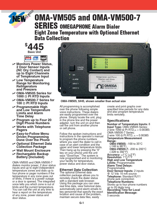
ߜ Wall Mount Enclosure
ߜ Rechargable Backup Battery (Included)
OMA-VM505 and OMA-VM500-7 dialers monitor power, 2 door status inputs and up to eight independent temperature zones and dials up to four phone or pager numbers if the temperature in any zone goes out of limits, if there is a power outage or a door is opened. The integrated voice tells you which zone is out of limits and the current temperature. You can call the unit at any time to hear a report on the temperature of any zone, power status and door status.
Ethernet Data Collection
The optional Ethernet data collection package allows you to remotely check the dialer status with a standard web browser. Using this package you can view real time data, view historical data, automatically send alarm emails to key personnel that specify the exact location and cause of the problem, maintain secure data files, easily
OKUMA CNC自动化指南说明书
OKUMA GUIDECNC AUTOMATIONAUTOMATION IN MANUFACTURING, THE USE OF COMPUTER-CONTROLLEDEQUIPMENT AND SOFTWARE TO PERFORM MANUFACTURING PRODUCTIONPROCESSES, was developed to improve quality, efficiency, and productivity inmanufacturing operations.From loading and unloading to conveyor or pallet systems, automation allows you to optimize the flow of production without an operator performing repetitive tasks.The following is a guide to all types of automation—when it was created,how it has evolved, and how it can benefit your shop.With precise actionsand timing, automationeliminates human errorfor seamless, highlyaccurate manufacturing.01 WHAT IS CNC AUTOMATION?Automation in manufacturing is not just the act of moving parts in and outof a machine. It involves designing an entire system to perform routine tasks automatically. From the planning phase, with software and control tools thatdrive data, to execution with robots or automation systems fulfilling those functions, automation takes steps to simplify manufacturing processes andbring consistency to routine operations.Leveraging CNC automation on the shop floor allows machines to do what they do best and people to do what they do best.An operator in front of a machine performing repetitive tasks such as loadingand unloading will never be as productive and consistent as a machine performing the same work. When these types of processes are automated,an operator can perform tasks that a machine can’t, such as critical process decision-making. In its best form, automation does not take away jobs; it allows for a more productive shop floor where machines and people are able to dotasks at which they are most efficient.02 THE HISTORY OF CNC AUTOMATIONThe idea of lights out manufacturing entered themanufacturing vocabulary by engineers in the late 1980s.In the beginning, automotive manufacturers were some ofthe earliest adopters, but today, the automation that makeslights out manufacturing possible is found in a wide varietyof industries and companies of all sizes.When working with some of the earliest automationsystems, every pickup point had to be taught to the robot.It was a time- and labor-intensive process which requireda dedicated robot programmer or integrator to manage, aswell as multiple technicians to keep them running.T oday, AI technology plays a key role in automation, bringing a level of smart decision-making and adaptability to manufacturing that previously wasn’t possible.03 BENEFITS OF CNC AUTOMATIONAny automation solution you seek to implement is designed to create a variety of benefits. With the ability to optimize your manufacturing processes, CNC automation solutions can increase your shop’s productivity, efficiency, and accuracy--and limit downtime, too. Shops that adopt automation also experience increased machine tool ROI. For example, when the market priceof a part or product is predetermined, the only way to ensure you’re getting the maximum ROI is to produce more parts than your competitors and ultimately lower costs.CNC automation can have a powerful impact on operators and other shop floor staff. Anything that is repetitive is a good candidate for automation—not just because automation brings efficiencies and results in reduced downtime, but because it can improve the operators’ physical and mental health when they’re no longer doing the same repetitive tasks and can focus on complex projects.Experience all the benefits automation can bring to your shop floor, including:• TACKLE MORE WORKMaximize spindle utilization. Automation enables continuous machining, which greatly increasesproduction efficiency, even during non-operational hours.• INCREASED PROFITABILITYLess time and material spent per part, lessdowntime, and more efficient operator utilization will lead to reduced costs.• REDUCED DOWNTIMEWith reduced human intervention, the risk ofmaking mistakes and the likelihood of unwanted downtime are decreased.• ATTRACT TALENTAppeal to and maintain a highly skilled workforce with engaging tasks, ergonomics, and safety. • SAVE ON UTILITIESOverhead costs such as lighting, HVAC, and even floor-space requirements can be reduced.• REDUCE SCRAPReducing human interaction provides greaterconsistency and lowers error rates.• INCREASED CONSISTENCY AND ACCURACY An automated machine will be more precisebecause of less human error and fewer setups,resulting in consistency across the board.• INCREASED COMPETITIVE ADVANTAGE The ability to produce the highest quality partpossible with high efficiency sets your shop apartfrom the competition.For manufacturers with high-volume production, introducing automation on the shopfloor can have a strong impact since the time savings from an automation solution canresult in more parts being made over time.And, for manufacturers with low-volume, high-mix production, an automated machinecan internalize functions that would otherwise be spread across several differentmachines. By putting those functions in a single machine, you simplify the automation.All you need is to get the part in and out of that machine.04 WOULD YOUR BUSINESS BENEFIT FROM CNC AUTOMATION?Automation has a wide variety of applications—manufacturers in any industry canutilize automation and see positive results. The scale of the improvement depends onthe type of manufacturing, level of production, and type of automation system utilized.It’s important to analyzewhere changes needto be made and wheremanufacturers wantto create efficienciesto identify the bestautomation solution tofit those needs.05 CONSIDERATIONS FOR INTRODUCINGCNC AUTOMATIONDuring considerations to add automation to your shop floor, it’s important to know baseline productivity to seek out benefits and make improvements. How much does it cost to make your part? What is your current spindle run time? Once you’ve established your current baseline, you can look ahead to how you can improve, whether that’s by cost, time, or streamlining labor.When you understand opportunities for improvement, you can easily identify anything in your processthat’s standing in the way of achieving success, take measures to fix those areas, and implement automated processes that will help you meet your goals.Start with the simplest, most recognizable barriers to meeting your goals. Once you’ve fixed the most obvious problems, you can track the data, see improvements, and potentially identify more areas that can be optimized.06 IMPLEMENTING CNC AUTOMATIONThere are many ways CNC automation can be implemented on the shop floor. In most machines, automation technology is built-in, allowing you to work on the machine and the automation controls simultaneously.In other cases, and for manufacturers who want to automate machines currently on their shop floor, a custom automation solution can be implemented.Depending on the type of machine you’re looking to automate, certain types of automation will serve a different purpose and will match better with certain machines.Prior to implementing an automation solution, operators and other technicians need training not only on the ins and outs of the machines but also on the new technologies they’ll be using. For a turnkey multi-robot system or a load-and-go system, it’s important to have training on your machine’s new automation functionality.BAR FEEDERS are an entry-level automation solution for most Okumalathes in a low-mix, high-production manufacturing environment. Witha consistency of production, bar feeders can provide regular time andmaterial savings over the course of operations, bringing higher efficiencyand leading to cost savings.AUTOMATIC PALLET CHANGERS use stationary pallet stands and apallet transfer unit on the compact structure of a single-level storagesystem to provide flexibility and productivity in a minimal footprint. APCscan provide hours of unattended machining for vertical lathes, machiningcenters, and double columns. Choose from in-machine, single-level, ortower APC options.FLEXIBLE MANUFACTURING SYSTEMS seamlessly operate numerousmachines—even different models. FMSs are configured to manufacture avariety of parts and are able to adapt to changing levels of production.OKUMA GANTRY LOADERS don’t have as much flexibility as a roboticcell but are able to perform faster, with a moving headstock that allowsthe loader to enter the machine regardless of turret position. OGLs areperfect for Okuma lathes or grinders. A built-in solution for efficient partload, unload, and turnover, OGLs significantly increase productivity.PRE-KITTED AUTOMATION CELLS are preconfigured automationpackages that are easy to integrate, quick to implement, and designed for all machine tool categories.07 TYPES OF CNC AUTOMATION SOLUTIONSDepending on your shop floor’s needs, different types of automation solutions operate in different waysand at different levels of control. Explore all of the automation solutions that may benefit your shop floor:For more information about Okuma products, contact your local Okuma distributor or schedule an appointment to visit us at one of the following locations:Okuma America Corporation11900 Westhall DriveCharlotte, NC 28278P: 704.588.7000Partners in THINC12428 Sam Neely RoadCharlotte, NC 28278P: 704.587.6789The Okuma Technical Center at Hartwig Houston 10321 Regal Row Houston, TX 77040P: 713.749.9600The Okuma Technical Center at Morris Midwest 2400 Vantage Drive Elgin, IL 60124 P: 630.351.1901© 2023 Okuma America Corporation Contact your local distributor at /distributorsINDUSTRIAL AND INTEGRATED ROBOTICS are pre-engineered solutionsfor straightforward integration with configuration flexibility for specificapplications.COBOTS are a collaborative and customizable automation solution withprogramming, speed, safety settings, and intelligent features for insightsinto smart manufacturing.OKUMA’S ROID SERIES features Okuma’s robot offerings, ARMROIDand STANDROID. ARMROID is built into the machine tool to maintain andstreamline operations. STANDROID is a standalone robot package thatprovides multifunctional and efficient manufacturing on a compact footprint.Both products in the ROID series provide flexibility to innovate at youroptimal level of control.。
三菱数控系统
三菱数控系统三菱数控系统的结构三菱数控系统的工作原理三菱数控系统的分类三菱数控系统的功能介绍三菱数控系统的结构三菱数控系统的工作原理三菱数控系统的分类三菱数控系统的功能介绍三菱数控系统的结构三菱数控系统由数控硬件和数控软件两大部分来工作的。
数控系统的硬件由数控装置、输入/输出装置、驱动装置和机床电器逻辑控制装置等组成,这四部分之间通过I/O接口互相连接运作的。
数控装置是数控系统的核心部分,通过它来实现我们的工作需求的。
三菱数控系统由控制系统,伺服系统,位置测量系统三大部分组成。
控制系统主要由总线、CPU、电源、存贮器、操作面板和显示屏、位控单元、可编程序控制器逻辑控制单元以及数据输入/输出接口等组成。
三菱数控系统的工作原理工作原理:控制系统按加工工件程序进行插补运算,发出控制指令到伺服驱动系统;伺服驱动系统将控制指令放大,由伺服电机驱动机械按要求运动;测量系统检测机械的运动位置或速度,并反馈到控制系统,来修正控制指令。
这三部分有机结合起来,组成完整的闭环控制的数控系统。
三菱数控系统的分类工业中常用的三菱数控系统有:M700V系列;M70V系列;M70系列;M60S系列;E68系列;E60系列;C6系列;C64系列;C70系列.三菱数控系统的功能介绍三菱数控系统M700V系列1.控制单元配备最新RISC 64位CPU和高速图形芯片,通过一体化设计实现完全纳米级控制、超一流的加工能力和高品质的画面显示。
2.系统所搭配的MDS-D/DH-V1/V2/V3/SP、MDS-D-SVJ3/SPJ3系列驱动可通过高速光纤网络连接,达到最高功效的通信响应。
采用超高速PLC引擎,缩短循环时间。
3.配备前置式IC卡接口。
4.配备USB通讯接口。
5.配备10/100M以太网接口。
6.真正个性化界面设计(通过NC Designer或c语言实现),支持多层菜单显示。
7.智能化向导功能,支持机床厂家自创的html、jpg等格式文件。
- 1、下载文档前请自行甄别文档内容的完整性,平台不提供额外的编辑、内容补充、找答案等附加服务。
- 2、"仅部分预览"的文档,不可在线预览部分如存在完整性等问题,可反馈申请退款(可完整预览的文档不适用该条件!)。
- 3、如文档侵犯您的权益,请联系客服反馈,我们会尽快为您处理(人工客服工作时间:9:00-18:30)。
以色列OMAT控制技术公司CNC数控加工优控系统OMAT的自动实时自适应进给速率控制铣削加工过程中的进给速率优化控制车削加工过程中的进给速率优化控制钻削加工过程中的进给速率优化控制磨削加工过程中的进给速率优化控制连接示意图一、功能说明1.概述虽然切削条件是随着切削过程变化而变化的,但数控机床的每步走刀都按程序编定的恒定进给量进行。
然而,如果将OMAT自适应控制器(优铣控制器OptiMil-XL,优车控制器OptiTurn-XL,优钻控制器OptiDrill-XL,优磨控制器OptiGrand-XL)与数控机床直接连接,就能实现监测实际的切削条件,并对每一步走刀的进给率自动地调节到最合适的数值。
OMAT自适应控制器保证用户不再受限于程序设定的进给速率。
这样可以在保护刀具避免被损坏的同时缩短加工周期。
OMAT的OptiMonitor-XL(优监控制器)连续地监测切削过程,只有在过载情况下才采取动作(停机或报警)2.刀具损坏保护在OMAT自适应控制系统的控制下,加工的参数会实时自动地适应刀具负荷和切削工况。
例如:在超载的情况下,即在突发事件中出现刀具或工件的冲击、工件毛坯的直径增加太大等,进给速率会自动减小到系统内部的专家系统所确定的最大允许值。
极端情况过去后,系统把进给速率增加到最大允许值。
使用OptiMonitor-XL时,每一步走刀“只采用监测”(而不是采用“进给控制”),当出现两种不同程度的过载时,LED 将用不同的发光颜色报告出现了以下两种不同程度的过载:a.停机程度过载:当过载达到了刀具的最大允许程度,例如:使用已经磨损坏的刀具、主轴和刀具过载时,系统的报警灯发红光,机床停止运动。
b.报警程度过载:当过载达到了这种程度时,系统的报警灯发黄光,这时可以选择性地让机床停止进给。
OptiDrill-XL配备了专门的算法以防止刀具的损坏,包括遇到极端情况的时候,例如:在“横穿孔”切削中。
3.主轴驱动保护OptiTurn-XL可以感受到什么时候切削负荷达到了主轴转动装置的最大允许值。
OptiTurn-XL感受到这一状态后就通过降低进给量给以响应,直到切削负荷落在可以接受的范围之内。
只要切削情况允许,OptiTurn-XL就把进给量提高到与最大允值切削负荷相对应的水平。
OptiMil-XL、OptiDrill-XL和OptiMonitor-XL对工况进行检测,以判断何时达到主轴的最大允许负荷,并在必要时停止机床以防止主轴和机床损坏,同时发出警报以提醒操作者。
4.为补偿刀具磨损进行自动的进给调节考虑到随着刀具的磨损,主轴的负荷会逐渐增加,OMAT自适应控制器可以保证能够刀具的磨损量来加以合适的进给量。
应用OMAT自适应控制系统,数控程序员不需要在编程设定进给量时过分保守。
可以象在使用崭新锋利的刀具情况一样设定进给量。
在切削过程中自适应控制器可以在整个切削过程中对刀具的磨损进行补偿。
这就意味着加工周期永远是最小的,并且没有以牺牲刀具的寿命作为代价。
5.刀具磨损的监测在生产中,OAMT优控系统可以通过加工第一件工件时学习对刀具磨损进行监测。
在随后的加工中,OMAT优控系统继续对刀具的状况进行监测,并按刀具的磨损程度占最大磨损程度的百分比来进行显示。
在必要时可以在程序结束时提醒操作者为了获得最大的切削效率而更换刀具。
如果某一钻削工序有预定的孔加工数目,那么在这一工序结束的时候,如果出现刀具过分磨损,那么OptiDrill-XL还可以提醒操作者更换刀具。
如果刀具的磨损达到了100%,OMA T优控系统可以启动专门的输出,这一输出可以接在外设上,例如:现成的备用刀具库。
6.刀具的损坏检测如果用户启用这一功能,OMAT的自适应控制器和OptiMonitor-XL可以在切削第一件工件时学习检测刀具的损坏。
在切削后续工件时如果出现刀具损坏,OptiMil-XL、OptiDrill-XL和OptiMonitor-XL马上给以响应,发出刀具损坏警报,停止机床的运动并接通专门的输出。
而这一输出可以接在外设上,例如:现成的备用刀具库。
OptiTurn-XL只有在当前走刀结束时才开始刀具的损坏响应。
7.刀具过载检测切削过程中,对任何一把特定的刀具,当实际的刀具负荷达到“报警”过载极限时,自适应控制器和OptiMonitor-XL予以响应,点亮过载LED以发出警报。
以便采取补救的办法,例如:及时更换刀具、修改进给量和主轴转速等。
使用OptiMonitor-XL时,当负荷达到“过载报警”程度时不需要任何动作,而在实际的刀具负荷达到“过载停机”程度时则停止机床以响应过载。
8.刀具寿命的延长在极度过载的情况下,OMAT自适应控制器降低进给速率。
这样在许多场合中可以减少刀具的磨损,进而延长刀具的使用寿命。
9.切削功率的监测OMAT自适应控制器和OptiMonitor-XL连续地显示走刀切削的实际功率。
这里的功率以占主轴额定功率的百分比来表示。
10、刀具性能统计数据在由OMA T自适应控制器和OptiMonitor-XL控制和监测的同时,可以将所有在切削过程中使用刀具的性能数据统计起来。
这些数据包括在自适应控制器参与和不参与控制情况下的切削时间、刀具的磨损和走刀切削过程中测到的最小进给倍率。
当前走刀切削的数据只有在走刀结束时才显示出来,但所累计的所有走刀数据可以在任何时候显示。
如果使用OMAT-Pro软件,则可以获得更为详细的统计数据。
11、冷却液监测使用OMAT优化系统时可以通过设置让其连续地监测冷却液的流量。
用户可以根据自己的愿望设置一个流量阀值,以便在切削过程中一直保持这个流量。
如果流量中断的时间达到了用户编程设置的时间长度,系统将停止机床的运动。
二、模式设置OMAT优化系统可以让用户针对每一步起刀选择一种控制功能,以使优化系统工作:1、完全优化模式:即实时的进给速率调节(在粗加工和半精加工中提高效率和动态的刀具保护)2、监测模式:(精加工过程中的刀具保护和过程监测):3、事件记录模式:仅仅进行数据记录,以便随后把记录的数据下载到安装了OMAT-Pro的PC机上。
一旦选择了某一种工作模式,在菜单上就只显示与该工作模式有关的参数。
对每一步切削走刀,刀具和工件的材料从系统的刀具库和材料库中选取,切削的参数也需要输入。
另外一种方法就是使用OMAT-Pro软件,在PC机上进行工序的设置,然后从PC上自动下载工序的设置数据。
工序中只需要对那些希望监测、自适应进给控制或事件记录的走刀步骤进行设置。
系统可以将大量的切削走刀数据(见技术规格)存储下来,以便随后在进行同样的加工时使用。
设置工序时,除了在程序中每次换刀的地方加入简单的程序字串外,不需要对已有的数控程序进行任何修改。
加入字串的目的是通知系统何时开始或停止。
另外每个开始指令还给系统一个通知,以告诉机床开始哪一步走刀。
如果安装了OMAT-Pro,这些数控字串可以通过OMA T-Pro自动插入到数控程序中。
三、操作设置完成之后,系统就自然进入自动模式,在整个切削过程中对那些设置过的切削走刀自动地进行控制。
OMAT自适应控制器通过识别在工序设置阶段选取的刀具和材料,使刀具的负荷保持在其最大允许水平上。
这就意味着控制器按照与每步切削走刀相适应的专门算法进行控制,而这种算法边续地根据测量到的负荷值计算出合适的进给速率。
最后机床实时地将这一进给速率应用到加工中。
OMAT自适应控制器在进行稳定连续的进给速率控制的同时,还在整个的切削范围内对所有的表面状况变化起刀具的动态保护作用。
OMA T自适应控制器在工作时不需要预先确定一个负荷极限值。
四、选项功能1、OMAT-ProOMAT控制系统的XL版本可以和OMAT-Pro软件配合使用。
OMAT-Pro是一套基于Windows的应用软件,该软件可以在PC机上或在连接到OMAT优控系统的PC网络上使用。
OMAT-Pro是一套现场管理人员的管理工具,它可以有效地监测和控制机床的生产。
作为机床的车间生产管理系统,OMAT-Pro集成了事件记录、生产性能监测和数据统计报告等功能。
OMAT-Pro能够报告和显示如下的生产、机床和刀具统计数据:✧机床的停机时间;✧机床和刀具的利用情况;✧机床的状态(例如:主轴的旋转状态、过载情况、是否处于切削状态等);✧完成加工的次数;✧加工完的工件数目;✧刀具、机床、操作人员和换班情况。
OMAT-Pro可以实时地、图形化地说明OptiMill-XL、OptiTurn-XL、OptiDrill-XL、OptiGrand-XL和OptiMonitor-XL如何控制数控机床的切削过程。
这些数据可以在PC机的屏幕上图形化地实时显示,经过处理还可以对切削过程提出总结。
切削过程中OMA T-Pro从OMAT控制系统接收事件数据。
OMAT-Pro记录和实时显示工序、走刀、刀具事件和报警等情况。
OMAT-Pro可以根据需要处理记录在PC机上与事件相关的数据,其后可以立即或过些时候以统计数据形式显示这些数据。
这些报告包括了有关生产工件、机床工作状况和刀具利用情况的综合信息。
借助于OMA T-Pro,用户可以在距离机床比较远的PC机上设置其OMAT控制系统,可以在PC机上产生切削工序的数据库。
另外,OMAT-Pro可以帮助设置工序参数、建立刀具库、管理工作参数库、编辑数控程序以及通过通信连接与OMAT控制系统进行数据交换等等。
有了OMAT-Pro,换了不同的工序不一定就非用手工方法往OMA T优控系统中输入数据,这对于重复加工特别有用。
不管有多少机床、多少刀具,OMA T-Pro都能够将相应的数据储存起来,即使涉及到最大范围的加工工作也能提供有效的支持。
2、数据记录仪这种可选系统是一种高度集成和便携式临时储存设备,可以储存工序和刀具的数据。
无论在车间现场环境还是在办公室环境,数据记录仪均可用于储存数据,也可用于在自适应控制器与安装了OMAT-Pro的PC机之间传输数据。
如果OMAT-Pro用户的机床与PC机之间没有RS232连接,推荐使用数据记录仪。
3、外部警报器除了标准的LED报警灯以外,还可以给OMA T自适应控制器配备外部警报器。
如果出现了各种极端情况,系统导致了机床的停止,这时就可以提醒机床的操作者。
五、应用实际上,OMAT优控系统是用来在加工过程上对主轴功率进行监测和对进给速率自动调节的。
以下列出了更为具体的应用场合:(附表1)六、安装安装是一次性过程,由OMAT授权的代表完成,安装分两个阶段:优控器与数控机床的连接OMAT优控器是通用的“附加”外设系统,实际上可以用来与任何数控机床连接。
虽然优控器的样式不断升级,却不需要对机床进行任何改动。
作为一整套完整的解决方案,优控器都包括一块I/O板。