清华大学数电课件
清华模电数电课件第29讲译码器

《数字电子技术基础》第五版
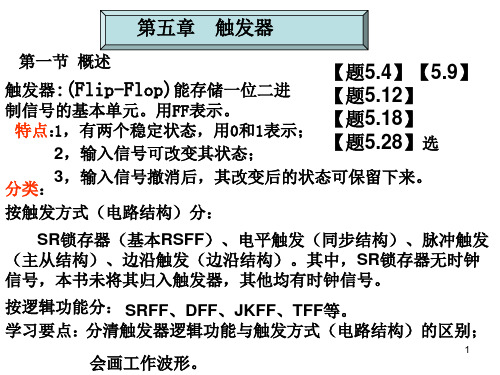
逻辑表达式:
用电路进行实现
《数字电子技术基础》第五版
集成译码器实例:74HC138
附加 控制端
S S3S2 S1
低电平 输出
Yi' ( S mi )'
74HC138的功能表:
《数字电子技术基础》第五版
输
入
输
出
S1
S
' 2
S
' 3
7448的附加控制信号:(3)
• 灭灯输入/灭零输出 BI ' RBO'
输入信号,称灭灯输入控制端: BI ' 0 无论输入状态是什么,数码管熄灭
输出信号,称灭零输出端:
只有当输入A3 A2 A1A0 0 ,且灭零输入信号 RBI ' 0 RBO' 才给出低电平
因此 RBO' 0 表示译码器将本来应该显示的零熄灭了
0 001
01 1 1 01 1 0
1
3
0 01 1
1 1 1 1 00
1
4
0 1 00
01 1 001
1
5
0 1 01
1 01 1 01
1
6
01 10
001 1 1 1
1
7
01 11
1 1 1 000
0
8
1 000
111111
1
9
1 001
1 1 1 001
1
10
1 010
A2
A1
A0 Y7'
Y6'
Y5'
Y4'
数电课件 第一章_清华

又如:(209.04)10= 2×10² +0×101+9×100+0×10-1+4 ×10⁻²
2、二进制 数码为:0、1;基数是2。 运算规律:逢二进一,即:1+1=10。 二进制数的权展开式: 如:(101.01)2= 1×22 +0×21+1×20+0×2-1+1 ×2 -2 =(5.25) 10
序
课程介绍 1. 课程的性质
言
2. 教学目标 3. 课程研究内容 4. 课程特点与学习方法 5. 教材和参考书 6. 对大家共同的要求
1.课程性质
《数字电子技术基础》课程是电子、电气、信息、计
算机、自动化类专业具入门性质的重要专业基础课。
2.教学目标
获得适应信息时代的数字电子技术方面的基本理论、
基本知识和基本技能。培养分析和解决实际问题的能力,
(4)片上系统(SoC):有些PLD集成度很高,足 以满足设计一般数字系统的需要,这样就可以由 设计人员自行编程将一个数字系统集成在一片 PLD上,做成“片上系统”,而不必去请厂家做 专用集成电路了。 (5)可编程片上系统(SoPC):是可编程的片上 系统。用可编程逻辑技术把整个系统放到一块芯 片上,具有灵活的设计方法,可裁剪、可扩充、 可升级,并具备软硬件在系统可编程的功能。 (6)在系统可编程器件(isp):编程不需要专门 的编程器,在计算机上就可以完成。
• 摩尔定律 :1965年时任仙童公司电子工程师 的戈顿· 摩尔在应邀为《电子学》杂志35周年 专刊写的文章中指出,芯片中的晶体管和电 阻器的数量每年会翻番。1968年与他人共同 创办了大名鼎鼎的芯片制造厂商Intel公司任 副总裁 。 1975年,摩尔在给IEEE学术年会 的论文中修正了摩尔定律,他认为,每隔24 个月,晶体管的数量将翻番。现在大家普遍 认同的是“集成电路芯片上所集成的电路的 数目,每隔18个月就翻一番”。
清华模电数电课件第29讲译码器

译码器可以将地址信号转换为外设接 口能够识别的信号,实现对外部设备 的访问。
04
译码器的使用注意事项
输入信号的电平要求
01
输入信号的电平应符合译码器的 规格要求,过高或过低的输入信 号可能导致译码器无法正常工作 或损坏。
02
输入信号的幅度和波形应保持稳 定,避免信号的突变或噪声干扰 导致译码器误动作。
电路组成
译码器、数码管、电源等。
用译码器实现数据分配的例子
数据分配
译码器可以将多路输入信 号分配到多个输出端,实 现数据的选择和分配。
工作原理
根据输入信号的不同,译 码器将对应的输出端置为 有效状态,从而实现数据 的选择和分配。
应用场景
在数据传输、存储、处理 等领域中广泛应用。
用译码器实现地址译码的例子
CD4514B芯片具有低功耗、高速、低噪声等优点,可在各种电
03
子设备中广泛应用。
03
译码器的应用场景
在显示电路中的应用
七段数码显示器
译码器可以将输入的二进制代码转换为七段数码显示器能够识别的电流信号, 从而显示数字。
LED显示器
译码器可以将二进制代码转换为LED显示器能够识别的电流信号,实现LED显示 器的数字显示。
地址译码
在计算机中,地址译码器可以将地址信号转换为对应的内存单元 或外设接口。
工作原理
根据地址信号的不同,译码器将对应的内存单元或外设接口置为有 效状态,从而实现数据的读取或写入。
应用场景
在计算机内存管理、外设接口控制等领域中广泛应用。
THANKS
感谢观看
译码器的分类
01
02
03
2-4线译码器
能够将2位二进制代码翻 译成4个输出信号,常用 于地址译码和数据分配。
2019清华大学数电5触发器课件.ppt
第五节 边沿触发的触发器 触发器的次态只取决于时钟信号上升沿(或下降沿)到 达时刻的输入信号的状态。 可统称为边沿结构。 它有三种构成方式:1. 用两个电平触发D触发器 构成。2.维持阻塞结构。 3.利用门电路传输延迟 时间构成。我们只介绍 图5.5.1(a) 第一种。 一.用两个电平触发D触发器构成 1.工作原理 23页 原理与主从结构的触发器相同。 24页波形 显然, 触发器的次态只取决于时钟信号上升沿到 达时刻的输入信号D的状态,与其他时刻的D值无关。 D锁存器12页 目前在CMOS集成电路中主要采 用这种电路结构形式制作边沿触发 21 回下页 器。请看CMOS边沿触发器:
3
三.工作原理 •SD’=1, RD’=0 不论原状态如何,都有: * '* Q 0, Q 1 --置0 1 1 •SD’=0, RD’=1 不论原状态如何 Q*=1 (略去Q’端) •SD’=1, RD’=1 若:Q=0,则Q*=0 若:Q=1,则Q*=1 •SD’=0, RD’=0 --不定 Q和Q’的次态都为1; --置1 0 1 --保持 0 R’D 1
1
第二节 SR锁存器(Set-Reset Latch)
一.电路组成:
RD 用与非门和或非 门均可构成,这里介 绍与非门构成的电路。
二. 状态和输入信号 •触发器的状态:
Q
S’D
Q
SD
Q’
Q’ R’D
用Q端的值表示。Q=1,Q´=0为1状态,反之为0状态。 原状态:观察的时刻的状态(输入信号没改变)。记为Q( Qn ) 。 新状态:输入信号变化后出现的状态。记为Q* (Qn+1 ) .也称次态。
S =D
R = D
CP上升沿时 电路按RSFF动作。注意到上式, 因此有 Qn+1=D 研究一下CP上升沿到来后的情 况,以判断它是不是边沿触发器: (1)若原来 D=0,则G4=0,使 得D变为1无影响; (2)若原来 D=1,则G4=1,但 G3=0,使得D改变仍无影响;
清华大学数电课件
Information resolves uncertainty. Information is simply that which cannot be predicted.
The less predictable a message is, the more information it conveys!
D+
G+ VGS - S -
VDS ≥ 0
Sequential logic: FSMs
PCSEL
ILL
XAd r
OP
JT
4
3
2
1
0
PC
00
+4
Instruction A
Memory
D
+
C: <15:0> << 2 si gn- ex tend ed
<PC>+4+C*4
IRQ
Z
Control Logic
Ra <20:16>
WA SEL
XP 1
Rc <25:21>
0
Z C: <15:0>
RA1 WAWA
RD1
Rb: <15:11> 0
Rc <25:21>
1
RA2SEL
Register File
JT C: <15:0>
si gn- ex tend ed
RA2 WD
RD2
WE
ASE L
1
0
1
0
BSEL
WE R F
wang_hong@
2011年 春季学期
编码的目的 二进制编码
清华模电数电课件第23讲数制与码制

《数字电子技术基础》第五版
10 – 5 = 5 10 + 7 -12= 5 (舍弃进位)
7+5=12 产生进位的模 7是-5对模数12的补码
• 1011 – 0111 = 0100 (11 - 7 = 4)
《数字电子技术基础》第五版
• 1011 + 1001 = 10100 =0100(舍弃进位)
1、 二进制算术运算的特点 算术运算:1:和十进制算数运算的规则相同 2:逢二进一
特 点:加、减、乘、除 全部可以用移位和相 加这两种操作实现。简化了电路结构
所以数字电路中普遍采用二进制算数运算
三、二进制数运算
2、 反码、补码和补码运算
《数字电子技术基础》第五版
二进制数的正、负号也是用0/1表示的。 在定点运算中,最高位为符号位(0为正,1为负) 如 +89 = (0 1011001)
(0101 ,1110 .1011 ,0010 )2
(5
E
B
2)16
4、十六-二转换
例:将(8FAC6)16化为二进制
(8
F
A
C
6)16
(1000 1111 1010 1100 0110 )2
《数字电子技术基础》第五版
5、八进制数与二进制数的转换
例:将(011110.010111)2化为八进制
(011 110 . 010 111)2
二、不同数制间的转换
1、二-十转换
《数字电子技术基础》第五版
D Ki 2i
例:
K (0,1)
(1011.01)2 1 23+0 22+1 21+1 20+0 2-1+1 2-2 =(11.25)10
《数字电子技术基础》第五版
清华数字电路第七章 半导体存储器PPT课件

16.08.2020
数电
7.1 概述
**PROM在出厂时存储内容全为1(或者全为0),用户 可根据自己的需要写入,利用通用或专用的编程器, 将某些单元改写为0(或为1)。
**PROM在出厂时存储内容全为1(或者全为0),用户 可根据自己的需要写入,利用通用或专用的编程器, 将某些单元改写为0(或为1)。
ROM可分为掩模ROM、可编程ROM(Programmable Read-Only Memory,简称PROM)和可擦除的可编程 ROM(Erasable Programmable Read-Only Memory, 简称EPROM)。
*掩模ROM在制造时,生产厂家利用掩模技术把数据 写入存储器中,一旦ROM制成,其存储的数据就固 定不变,无法更改。
第七章 半导体存储器
内容提要
本章将系统地介绍各种半导体存储器的工作原理 和使用方法。半导体存储器包括只读存储器(ROM) 和随机存储器(RAM)。在只读存储器中,介绍了掩 模ROM、PROM和快闪存储器等不同类型的ROM的 工作原理和特点;而在随机存储器中,介绍了静态 RAM(SRAM)和动态RAM(DRAM)两种类型。 此外,也介绍了存储器扩展容量的连接方法以及用存 储器设计组合逻辑电路,重点放在这里。
1. ROM的组成:
ROM电
路结构包含存
储矩阵、地址
译码器和输出
缓冲器三个部
分,其框图如
图7.2.1所示。
16.08.2020
数电
图7.2.1
7.2.1 掩模只读存储器
a.存储矩阵
存储矩阵是由许多存储单元排列而成。存储单元 可以是二极管、双极型三极管或MOS管,每个单元能 存放1位二值代码(0或1),而每一个或一组存储单元有 一个相应的地址代码。
清华大学《数字电子技术基本教程》教学课件.pptx

与X、Q有关 仅取决于电路状态
6.2 时序电路的分析方法
《数字电子技术基本教程》
分析:找出给定时序电路的逻辑功能 即找出在输入和CLK作用下,电路的次态和输出。
一般步骤:
①根据给定的逻辑图写出存储电路中每个触发器输入端的逻 辑函数式,得到电路的驱动方程。
R’D S1 S0 工作状态 0 X X 置零 1 0 0 保持 1 0 1 右移 1 1 0 左移 1 1 1 并行输入
《数字电子技术基本教程》
6.3.3 计数器
• 用于计数、分频、定时、产生节拍脉冲等
• 分类: 按时钟分,同步、异步 按计数过程中数字增减分,加、减
……
1. 异步计数器
异步二进制加法计数器 在末位+1时,从低位到高位逐位进 位方式工作。 原则:每1位从“1”变“0”时,向高
6.1 时序逻辑电路的特点和逻辑功能的描述 一、时序逻辑电路的特点 1. 功能上:任一时刻的输出不仅取决于该时刻的输入,还
与电路原来的状态有关。 例:串行加法器,两个多位数从低位到高位逐位相加
2. 电路结构上 ①包含存储电路和组合电路 ②存储器状态和输入变量共同决定输出
《数字电子技术基本教程》
二、时序电路的一般结构形式与功能描述方法
因为 触发器有延迟时间t pd 所以 CLK 到达时,各触发器按前一级触发器原来的状态翻转
数据依次右移1位
《数字电子技术基本教程》
应用: 代码转换,串 并 数据运算
《数字电子技术基本教程》
器件实例:74LS 194A,左/右移,并行输入,保持,异步 置零等功能
并行输入
并行输出
《数字电子技术基本教程》
清华数电数据选择器加法器数值比较器竞争冒险现象PPT课件
第1页/共23页
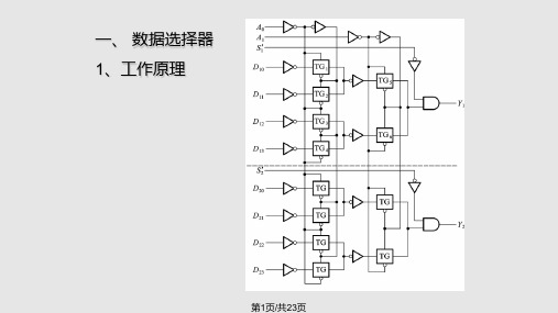
• 例:“双四选一”,74HC153
•
分析其中的一个“四选一”
Y1 S1[D0 ( A1' A0' ) D1( A1' A0 ) D2 ( A1 A0' ) D3( A1A0 )]
S1' A1 A0 Y1
1 XX0 0 0 0 D10 0 0 1 D11 0 1 0 D12 0 1 1 D13
第2页/共23页
例:用两个“四选一”接成“八选一”
• “四选一”只有2位地址输入,从四个输入中选中一个 • “八选一”的八个数据需要3位地址代码指定其中任何一个
利用S '作为第3位地址输入端
Y ( A2' A1' A0' )D0 ( A2' A1' A0 )D1 ( A2' A1A0' )D2 ( A2' A1A0 )D3 ( A2 A1' A0' )D4 ( A2 A1' A0 )D5 ( A2 A1A0' )D6 ( A2 A1A0 )D7
1、1位数值比较器
A,B比较有三种可能结果
A B( A 1, B 0)则AB' 1,Y( AB) AB' A B( A 0, B 1)则A'B 1,Y( AB) A'B A B( A, B同为0或1),Y( AB) ( A B)'
第14页/共23页
2、多位数值比较器
00
01
01
01
01 10
10
入
BA 00 01 10 11 00 01 10 11 00 01
输出
Y3 Y2 Y1 Y0 001 1 01 00 01 01 01 1 0 01 1 1 1 000 1 001 1 01 0 1 01 1 1 1 00
清华大学数电4组合课件
G1门是 非门, 强调低 电平有 效
YS ' ( I 0 ' I1 ' I 2 ' I 3 ' I 4 ' I 5 ' I 6 ' I 7 ' S )'
YEX ' (YS ' S )'
S’是“使能”信号 低电平有效 代表无输入信号 11
代表“有输入信号”
Y2' [( I 7 I 6 I 5 I 4 ) S ]'
一、编码器(Encodor)
编码: 用二值代码表示具体事物(变量)。 如:用0101表示十进制数5。 编码器分为普通编码器和 优先编码器。 (一)普通编码器 普通编码器任何时刻只允许 一个输入有效。 以3位二进制编码器的设计 为例:
注意这个名称
8
1.真 值表
2.函数式
' ' ' ' ' ' ' ' ' ' ' ' Y2 I 7 I 6 I 5 I 4 I 3 I 2 I1' I 0 I 7 I 6 I 5 I 4 I 3 I 2 I1' I 0
Z 3 m ( 2,3,5) ( m m m )
' 0 ' 2
' ' 5 ' 4 ' ' 7
Z 4 m (0,2,4,7 ) ( m m m m )
由于译码器输出 低电平有效,故 选用与非门
25
(四)显示译码器 1.七段字符显示器 这种显示器可用多种发光器件构 成。例如半导体发光二极管、液晶等。 这里以发光二极管为例进行说明。 半导体数码管BS201A的外形图、 等效电路: 驱动电路 共阴极接法 VCC T R 共阳极接法 VCC D
数字电路课件(第二章)
4
5 6 7 8 9
A A′= 0
AB=BA A (B C) = (A B) C A (B +C) = A B + A C (A B) ′ = A′ + B′基础》第五版
公式(17)的证明(真值表法):
ABC BC A+BC A+B A+C
(A+B)(A+C)
0 0 0 1 1 1 1 1
000 001 010 011 100 101 110 111
0 0 0 1 0 0 0 1
0 0 0 1 1 1 1 1
0 0 1 1 1 1 1 1
• 卡诺图 • EDA中的描述方式 HDL (Hardware Description Language)
VHDL (Very High Speed Integrated Circuit …) Verilog HDL
EDIF DTIF 。。。
《数字电子技术基础》第五版
举例:举重裁判电路
A B C Y
3
《数字电子技术基础》第五版
最小项的编号:
最小项
A B C A B C A B C A BC A B C A B C AB C ABC
取值 对应 A B C 十进制数 0 0 0 0 0 0 1 1 0 1 0 2 0 1 1 3 1 0 0 4 1 0 1 5 1 1 0 6 1 1 1 7
非
• 条件不具备,结果发生 • Y A NOT A
清华数字电路课件第六章-时序逻辑电路

YF(Q)
仅取决于电路
6.2.时序逻辑电路的分析方法
6.2.1 同步时序逻辑电路的分析方法
时序逻辑电路的分析:就是给定时序电路,找出该的 逻辑功能,即找出在输入和CLK作用下,电路的次态和 输出。由于同步时序逻辑电路是在同一时钟作用下, 故分析比较简单些,只要写出电路的驱动方程、输出 方程和状态方程,根据状态方程得到电路的状态表或 状态转换图,就可以得出电路的逻辑功能。
6.2.时序逻辑电路的分析方法
(4)状态转换表:
Q Q12n n 1 1 D D12Q A1Q1Q2
A=0时
Y [ A Q 1 ( Q 2 ) ( A Q 1 Q 2 ) ] A Q 1 Q 2 A Q 1 Q 2 A=1时
Q2 Q1 Q2* Q1* Y
00 0 1 0 01 1 0 0 10 1 1 0 11 0 0 1
J3 Q1Q2,
K3 Q2
6.2.时序逻辑电路的分析方法
(2) 状态方程:
JK触发器的特性方程
Q *JQ KQ
将驱动方程代入JK触发器的特性方程中,得出电 路的状态方程,即
J1 (Q2Q3), K1 1
J2 Q1,
K2 (Q1Q3)
J3 Q1Q2,
K3 Q2
(3)输出方程:
QQ2*1*Q(1QQ22Q3)Q1QQ31Q2 Q3*Q1Q2Q3 Q2Q3
YQ2Q3
6.2.时序逻辑电路的分析方法
6.2.2时序逻辑电路的状态转换表、状态转换图、状态 机流程图和时序图
从例题可以看出,逻辑电路的三个方程应该说已 经清楚描述一个电路的逻辑功能,但却不能确定电路 具体用途,因此需要在时钟信号作用下将电路所有的 的状态转换全部列出来,则电路的功能一目了然
清华数字电路设计课件_时序_791906702
Outline•Introduction(1,2,3,4)•Combinational Logic Design(3,5)•Sequential Logic Design(6,7,8)•Memory & PLD(9)•Summary1/Finite State Machines Design•Concept of Finite State Machine •Counters (7)•Basic FSM Design Approach (8)–FSM Design Procedure–Other State Reduction Method–Other State Assignment–FSM Partitioning2/Understand the problem•From the word specifications•Counters–Enumerate the sequence•General FSM–Try some input sequences–Under what conditions FSM transitionsbetween states–The various outputs are asserted4/Obtain an abstract representationof the FSM•Constructing a state table or state diagram, which is an abstract model of the network behavior–No standard technique–Define a prior set of states needed by thenetwork to preserve the information regardingthe past history of inputs•Initial state•Additional states: none of the defined statesadequately describes the information to bepreserved at some point in time5/Perform State Minimization•By means of state reduction technique •Determining equivalent pairs of states •Obtaining the equivalence classes ofstates•Constructing the minimal state table6/Algorithm for Determiningequivalent pairs of states •Construct an implication table•Place a×, √, or next states in every cell •Inspect all state pair entries in the implication table•Repeat Step 3 until all cells are inspected8/Assignment Method•Sequential Encoding–Binary Up-Counting Order–Gray•Random Encoding•One-hot Encoding•Output-Oriented Encoding•Heuristic Methods10/Guidelines Based on Next Stateand Inputs/Outputs•Highest Priority–States with the same next state for a given inputtransition should be given adjacent assignments •Medium Priority–Next states of the same state should be givenadjacent•Lowest Priority–States with the same output for a given input shouldbe given adjacent assignments•Initial state is assigned with 00 011/Implement the FSM•After state assignment, an excitation tableis constructed based on the flip-flop typesto be used in the realization•From the excitation table, the excitationand output expressions for the network are determined•The logic diagram is drawn12/Moore & Mealy Machines•Mealy–The outputs from a Mealy sequential networkare a function of both the external inputs andthe present state•Moore–The outputs from a Moore sequential networkare only a function of the present state13/Moore & Mealy Outputs•Moore Outputs are synchronous with the clock–Have a disciplined timing methodology •Mealy Outputs are asynchronous because they can change in response to any changes in the inputs–Synchronous variation16/Comparison of the Two Machine Types•Moore–Synchronous–More states•Mealy–reduced state count–asynchronous20/Two Major Issues with Mealy Machine• The output logic of Mealy machines can cause glitches on the output • The output can change asynchronously to the clock– Sometimes be an advantage – The circuit can react quickly to an input change rather than having to wait for the next clock edge to advance the state21/Timing Diagramclock x y Q1 Q2 zA B D C A Cz = xQ1 + Q1Q2DACA? 1 1 0 1 1 1 0??? 1 1 022/Mealy; The values of the external input variables only at the triggering time of the clock signal are considered;Synchronous Mealy MachineCombinational Logic to Compute Outputs Combinational Logic to Compute Next State Re- Outputs gister Current State RegisterI n p u t s23/Finite State Machines Design• Concept of Finite State Machine • Counters (7) • Basic FSM Design Approach (8)– FSM Design Procedure – Other State Reduction Method – Other State Assignment – FSM Partitioning24/Other State Reduction Method• Implication Chart • Row matching– Combine the two approaches – Firstly, row matching quickly reduces the number of states – Then, implication chart, now working with fewer states, finds the equivalent states missed by row matching more rapidly• Equivalent states in the presence of don’t cares • When state minimization doesn’t help25/Implication Chart MethodPresent Next State State x=0 x=1 A* B C D E F G A D F D B G A B C E F G C F Output x=0 x=1 0 0 0 0 0 0 0 0 1 0 0 0 1 026/Row Matching• Get the state transition table with multiple next-state and output columns based on the input combinations • Examine the rows of the state transition table to find any with identical next-state and output values—Row Matching • Continue matching rows until any can’t be no longer combined—Row-matching Iteration27/Modeling the sequence detector• The FSM produce a 1 output if and only if the current input and the previous three inputs correspond to either of the sequences 0110 or 1010. The machine returns to the reset state after each and every 4-bit sequence x=0010 0110 1100 1010 0011 z=0000 0001 0000 0001 000028/A*: reset B: input 0 received C: input 1 receivedState tableD: input 00 received E: input 01 received F: input 10 received G: input 11 received0/0 BA1/01/0 0/0 1/0 0/0 D E F G 0/0 1/0 0/0 1/0 0/0 1/0 0/0 1/0 H I J K 0/1 L M 0/1 N OCH: input 000 received I: input 001 received J: input 010 received K: input 011 received L: input 100 received M: input 101 received N: input 110 received O: input 111 received29/Input Sequence Reset 0 1 00 01 10 11 000 001 010 011 100 101 110 111Present State A B C D E F G H I J K L M N ONext State x=0 x=1 B C D E F G H I J K L M N O A A A A A A A A A A A A A A A AOutput x=0 x=1 0 0 0 0 0 0 0 0 0 0 0 0 0 0 0 0 0 0 0 0 1 0 0 0 1 0 0 0 0 0Row Matching Iteration (1)Advantages of Implication Chart•Be Straightforward•Be efficiently implemented in software35/Equivalent states in the presenceof don’t cares•If having don’t care, the problem becomes much more difficult–Input don’t cares•The state can be chosen to transition for aninput combination that is impossible•Merging more states–Output don’t cares•More problematic•Two methods rely on output patterns as acentral part of determining stateequivalence36/When state minimization doesn’t help•Advantages of State Minimization–Allow us to build smaller finite state machineswith less flip-flops and less logic•The logic equations themselves can become more complex as we fit more states into a smaller number bits–用更少的位数表示更多的状态–逻辑函数本身更复杂–Leading to a less efficient realization38/Edge Detector FSM•Moore•Detect when consecutive inputs change from 0 to 1•Output a 1 when detecting this “rising edge”in our input dream39/Minimizing states isn’t always the best thing•Leading a larger and non-obvious implementation•State Reduction is still an art•Not Straightforward as we mentioned introducing Row-matching and Implication TableQ1+=XQ1Q0’+XQ1’Q0 Q0+=XQ1’Q0’Z=Q1’Q0Q1+=Q0Q0+=XZ=Q1’Q044/Finite State Machines Design•Concept of Finite State Machine •Counters (7)•Basic FSM Design Approach (8)–FSM Design Procedure–Other State Reduction Method–Other State Assignment–FSM Partitioning45/Assignment Method•Sequential Encoding–Binary Up-Counting Order–Gray•Random Encoding•One-hot Encoding•Output-Oriented Encoding•Heuristic Methods–Minimum Bit-Change Heuristic–Guidelines based on next-state andinput/outputs46/Traffic Light Controller•As long as no vehicle is detected on the farm road, the lights should remain green in the highway direction•If a vehicle is detected on the farm road, the highway lights should change from green to yellow to red,allowing the farm road lights to become green•The farm road lights stay green only as long as a vehicle is detected on the farm road and never longer than a set interval so as not to block traffic flow along the highwayfor too long•Then farm road lights change from green to yellow to red, allowing the highway lights to return to green•Even if vehicles are waiting to cross the highway, the highway should remain green for a minimum amount oftime48/49/Inputs & Outputs & States •Inputs–Reset: Place controller in initial state–C: Detects vehicle on farm road in either direction –TS: short timer interval has expired–TL: long timer interval has expired•Outputs–ST: Reset timer and start timing long & short intervals –H 1H 0:Light at Highway–F 1F 0:Light at Farm RoadStates•HG: Highway green (farm road red)•HY: Highway yellow (farm road red)•FG: Farm road green (highway red)•FY: Farm road yellow (highway red)50/。
清华模电数电课件第12讲互补输出级

电磁兼容性问题
总结词
电磁兼容性问题是指电子设备在电磁环境中 工作时,可能受到其他设备的电磁干扰,同 时也可能对其他设备产生电磁干扰。
详细描述
解决电磁兼容性问题需要从多个方面入手, 如加强屏蔽措施、优化接地设计、合理布线 等。此外,还可以通过采用滤波、退耦等措 施来降低电磁干扰的影响。在设计和生产过 程中,应遵循相关国家和国际标准,以确保 产品的电磁兼容性符合要求。
互补输出级的电压增益主要由两个晶体管的β值决定,而输出阻抗则由两个晶体管的 并联电阻决定。通过适当的设计和匹配,可以获得较高的电压增益和较低的输出阻 抗。
电路组成
互补输出级通常由两个晶体管、输入和输出变压器、偏置电阻和电容等元件组成。其中,输入变压器将输入信号耦合到互补 输出级的输入端,而输出变压器则将放大后的信号耦合到负载。偏置电阻和电容用于为晶体管提供适当的偏置电压和直流工 作点。
运行。
03
互补输出级的电路设计
电路参数选择
电压参数
根据电路需求,选择合 适的电源电压,确保电
路正常工作。
电流参数
根据负载需求,选择合 适的电流容量,确保电 路能够提供足够的驱动
能力。
频率参数
根据电路功能,选择合 适的频率范围,以满足 信号处理或传输的需求。
功率消耗
考虑电路的功率消耗, 合理选择电源和散热方 案,以确保电路稳定可
。
04
互补输出级的实际应用
在音频放大器中的应用
音频放大器是互补输出级最常见的应用领域之一。互补输出级能够提供高效率、低 失真和高动态范围的音频输出,因此在音频放大器设计中被广泛采用。
它通常用于驱动扬声器或其他音频负载,提供清晰、动态的音频效果,满足各种音 频应用的需求。
- 1、下载文档前请自行甄别文档内容的完整性,平台不提供额外的编辑、内容补充、找答案等附加服务。
- 2、"仅部分预览"的文档,不可在线预览部分如存在完整性等问题,可反馈申请退款(可完整预览的文档不适用该条件!)。
- 3、如文档侵犯您的权益,请联系客服反馈,我们会尽快为您处理(人工客服工作时间:9:00-18:30)。
• What makes a good system design?
– minimal mechanism, maximal function – reliable in a wide range of environments – accommodates future technical improvements
7
数字量和模拟量
2011年 春季学期
• 数字量:在时间上和数量上都是离散、不连续的。 (存在一个最小数量单位△)
• 模拟量:数字量以外的物理量。
wang_hong@
Problems with Continuous Things • Which one is 桃红色?
2011年 春季学期
wang_hong@
2011年 春季学期
编码的目的 二进制编码
第一章 信息和编码
wang_hong@
Encoding 编码
2011年 春季学期
• Encoding describes the process of assigning representations to information
• 模拟量:数字量以外的物理量。
• 数字电路和模拟电路: 工作信号、研究的对象、分析/设计方法以及所用的 数学工具都有显著的不同。
wang_hong@
2011年 春季学期
wang_hong@
3
2011年 春季学期
2011年 春季学期
wang_hong@ 2011年 春季学期
• 70 minutes of music ≈ ? Bits • A4-sized picture ≈ ? Bits • 2 hours of movie (DVD) ≈ ? Bits
• Information carried in continuous things may be of higher density and processed quicker
wang_hong@
How do you build systems with >1G components?
2011年 春季学期
Personal Computer: Hardware & Software
MOSFET
Circuit Board: ≈1~8 / system 1-2G devices
Imprecise in communication
wang_hong@
2
2011年 春季学期
But Continuous Carries Huge Info. • Let us use “bits” as an indicator of the
amount of information
wang_hong@
什么是电子技术
2011年 春季学期
是研究电子器件及电子器件应用的一
门学科
通过控制器件中电子的 运动而进行工作
wang_hong@
数字量和模拟量
2011年 春季学期
• 数字量:在时间上和数量上都是离散、不连续的。 (存在一个最小数量单位△)
wang_hong@
电路原理
2011年 春季学期
模拟电子技术基础 数字电子技术基础
电子技术基础实验
电子技术课程设计 微型计算机原理
wang_hong@
2011年 春季学期
课程在培养方案中的位置 课程的任务
数字电子技术基础 绪论
wang_hong@
– Systematic approaches
– Algorithms
– Diagnose, fix, and avoid bugs
wang_hong@
5
2011年 春季学期
Logic gates Combinational logic circuits
MOSFets & Voltages
– Color – Light – Cars – Sound – Height and weight – Dogs – Electric current and voltage – English letters
Many natural phenomena are continuous
wang_hong@
PCSEL RA2SEL ASE L BSEL WD SEL AL UFN Wr WERF
WA SEL
A
B
AL UFN
AL U
WD
R/W
Wr
Data Memor y
Ad r RD
<PC>+4
01 2
W DS E L
wang_hong@
What is “Information 信息”?
2011年 春季学期
• 课程的性质:入门性质的技术基础课 • 课程目的:掌握基本概念、基本设计和分析的方法、
以及基本实验技能;具有能够继续深入学习和接受 电子技术新发展的能力,以及将所学知识用于本专 业的能力。 • 学习方法:入门阶段以听课为线索,强调实践环 节;建立工程的观念、系统的观念、科学进步的观 念和实践的观念。
• Study organizational principles: abstractions, interfaces, API
• Roll up our sleeves and design at each level of hierarchy
• Learn engineering tricks
– History
• Choosing an appropriate and efficient encoding is a real engineering challenge
• Impacts design at many levels
- Mechanism (devices, # of components used) - Efficiency (bits used) - Reliability (noise) - Security (encryption)
D+
G+ VGS - S -
VDS ≥ 0
Sequential logic: FSMs
PCSEL
ILL
XAd r
OP
JT
4
3
2
1
0
PC
00
+4
Instruction A
Memory
D
+
C: <15:0> << 2 si gn- ex tend ed
<PC>+4+C*4
IRQ
Z
Control Logic
2011年 春季学期
主讲:
王 红 (自动化系)
EDA实验室教师:陈莉平 秦俭
助教:李积惠 王新攀 王彦兵
答疑地点:
中主楼 700C 或705
集中答疑时间: 周四下午 3:00 ~ 5:00(暂定)
考核方式:平时 + 开卷考试(期中,期末) 作业:每周交一次(请各班课代表与助教联系) 教学秩序:。。。。。。。。。。。。。。。。。
information, n. Knowledge, communicated or received concerning a particular fact or circumstance.
中国男足又输了
2011年 春季学期 “Really, 取消考试 !”
Tell me something new…
Ra <20:16>
WA SEL
XP 1
Rc <25:21>
0
Z C: <15:0>
RA1 WAWA
RD1
Rb: <15:11> 0
Rc <25:21>
1
RA2SELRegiste源自 FileJT C: <15:0>
si gn- ex tend ed
RA2 WD
RD2
WE
ASE L
1
0
1
0
BSEL
WE R F
wang_hong@
6
2009010965
• 数制:表示数量的规则 • 码制:表示事物的规则
2011年 春季学期
wang_hong@
十进制,二进制,八进制,十六进制
2011年 春季学期 逢二进一
逢八进一
逢十进一
逢十六进一 wang_hong@
16-64 devices
8 devices
wang_hong@
2011年 春季学期
Our plan of attack…
• Understand how things work,
bottom-up
• Encapsulate our understanding using appropriate abstractions
wang_hong@
1
电路原理
2011年 春季学期
模拟电子技术基础 数字电子技术基础
电子技术实验
电子技术课程设计 微机原理与应用
wang_hong@
2011年 春季学期
Continuous versus Discrete
• Which are “continuous”?
wang_hong@
wang_hong@
电子技术的发展
2011年 春季学期
Electronic Design Automation
EDA
• 48年 • 58年 • 69年 • 75年
•…
