Spin Transport in Two Dimensional Hopping Systems
线粒体解耦联蛋白2介导硫化氢对帕金森病模型鼠的神经保护作用

lrd n mis su y Th p a e tfe p c s t e c n r lp t fACh G4, c a gn r m a y a c t d . e a p r n r e s a e wa h e ta a h o E h n ig fo
数 ,与对照组进行比较。对照组首次扭体时间为 24 3 、1 、5m / g 1 ±4 。2 0 0 g k 扭体数为 2 4 9 8 土9 , 24 6 0 ±15 2 士7 ,3 6 4 ,所用剂量有一定延长首次扭体时间作 。 对照组扭 体数为 1. 士6 6 、1 、5m / g扭体 数为 l. ±6 1 35 . ,70 78 . 。2 0 0 g k O 2 . ,1. ±4 3 . 土 39 。2 0 g k 有一定 的止痛作用 ,5 m / g 明显减少醋酸引起 的小 鼠扭体次数。 .一 、1m / g 0 gk 可
徐瑞 明
中国医学 科学 院药 物研 究所
北京
10 5 0 00
雄 性 昆明小 鼠 ,体重 1" 2 g 8- 2 ,禁 食 过 夜 后灌 胃给 予 D G1 82 0 0 / g 0分 钟 后 - J 0 、1 、5mg k 。3 腹 腔注 射 0 7 醋 酸 0 1 /0 . .ml1g体重 。观 测小 鼠在 注 射 醋 酸后 首 次 扭 体 时 膜电位决定产生动作电位的阈值 ,参与神经保护 、脑血 管舒张 以及肾上腺皮质激素分泌等生理功能 。另外 ,该通道还与抑郁症 和肿瘤病 理密切相关。
尽管 已知 T E —l R K 的活性受胞内外许多信号的调控 ,但其详细的门控机制却知之甚少 。为进一 步探索该通道的功能 ,本课题拟探讨 T E R K一1 离子选择器构象 的变化对该通道 电流 的调控作 用。【 研究 结果】 :首先 ,我们发现胞外应用 B 。 可强烈抑制 T E - 1 a + R K- 通道 电流 ,这种抑制呈 时间和浓度依赖性 。进一步的点突变研究表 明,B 。通过 与该通道离子选择器 内第 四个钾离子 a + 结合位点 (4 S )结合来发挥这种抑制作用 。根据 B 的这种特性 ,我们 以该离子为工具 ,对该 a +
物质的跨膜运输与信号传递

第二节 细胞的信号跨膜传递
一、概述 一细胞通讯 概念: 生物体内C与C之间的联络、识别以及信息传递是指一个细胞发出的信息通过介质传递到另一个细胞并与靶细胞相应的受体相互作用然后通过信号转导产生胞内一系列生理生化反应最终表现为细胞整体的生物学效应的过程
细胞通讯一般包括下列几个步骤: ① 信号细胞合成并释放信号分子; ② 信号分子运送至靶细胞; ③ 信号分子与受体的特异性结合及其激活; ④ 信号转导与传递; ⑤ 引发细胞功能、代谢或基因表达的改变; ⑥ 信号的解除与细胞反应的终止
配体:能通过细胞膜的亲脂性小分子如甾类激素等 受体:基因调控蛋白;有三个结构域:①C端的激素结合域; ②N端的转录激活域; ③中部的抑制蛋白或DNA结合域 如NO信号分子近年发现的一种亲脂性信号分子: ①性质:是一种自由基性质的气体分子具脂溶性可快速扩散透过细胞 膜到达靶细胞发挥作用但寿命很短半衰期只有5s左右 ②产生:由神经细胞和血管内皮细胞在一氧化氮合酶催化下分解精氨酸产 生 ③靶分子:细胞质中的鸟苷酸环化酶活化鸟苷酸环化酶产生cGMP ④效应:cGMP作为新的信号分子介导下游蛋白质的磷酸化引起血管扩 张血液畅通;参与大脑记忆等过程
2、由ATP间接供能的主动运输-协同运输 1同向协同:如小肠上皮细胞对葡萄糖的吸收就是伴随着Na+的进入 2反向协同:如红细胞膜上Na+与HCO3 -的进入伴随着Cl-和H+的外流 3、利用光能的主动运输:如细菌质膜视紫红质可吸收光能将两个H+ 从细胞内运出
Hale Waihona Puke 二、离子泵参与主动运输的载体蛋白常被称为泵pump这是因为它们能利用能量做功由于它们消耗的代谢能多数来自ATP所以又称它们为某某ATPase P-型离子泵:Na+/K+泵、Ca2+泵 V-型质子泵 F-型质子泵 ABC超家族
氯化石蜡的环境分析方法研究进展

引用格式:周婷婷, 杨倩玲, 翁冀远, 等. 氯化石蜡的环境分析方法研究进展[J]. 中国测试,2024, 50(4): 1-15. ZHOU Tingting,YANG Qianling, WENG Jiyuan, et al. A review on analysis of chlorinated paraffins in environment[J]. China Measurement & Test,2024, 50(4): 1-15. DOI: 10.11857/j.issn.1674-5124.2022080162氯化石蜡的环境分析方法研究进展周婷婷1,2,3, 杨倩玲1,2,3, 翁冀远1,3, 乔 林1, 高丽荣1,2,3, 郑明辉1,2,3(1. 中国科学院生态环境研究中心,环境化学与生态毒理学国家重点实验室,北京 100085;2. 国科大杭州高等研究院 环境学院,浙江 杭州 310000; 3. 中国科学院大学,北京 100049)摘 要: 短链氯化石蜡(SCCPs )具有持久性、生物毒性和生物累积性等,是一种持久性有机污染物,被列入《斯德哥尔摩公约》附件A 中,中链氯化石蜡具有SCCPs 相似的性质也备受关注。
氯化石蜡(chlorinated paraffins ,CPs )拥有成千上万种同系物、异构体、对映体,加之环境基质中存在其他有机卤素化合物,CPs 分离分析困难,目前我国仍没有环境样品中CPs 分析的标准方法。
该文对近年来不同环境基质中的CPs 分析所采用的样品前处理技术和仪器分析方法两个方面进行综述,提供CPs 分析方法最新发展动态,为相关人员对开展此方面的研究提供参考。
关键词: 短链氯化石蜡; 中链氯化石蜡; 分析方法; 前处理方法中图分类号: TB9; X-1文献标志码: A文章编号: 1674–5124(2024)04–0001–15A review on analysis of chlorinated paraffins in environmentZHOU Tingting 1,2,3, YANG Qianling 1,2,3, WENG Jiyuan 1,3, QIAO Lin 1, GAO Lirong 1,2,3, ZHENG Minghui 1,2,3(1. State Key Laboratory of Environmental Chemistry and Ecotoxicology, Research Center for Eco-Environmental Sciences, Chinese Academy of Sciences, Beijing 100085, China; 2. School of Environment, Hangzhou Institute for Advanced Study, University of Chinese Academy of Sciences, Hangzhou 310000, China; 3. University of ChineseAcademy of Sciences, Beijing 100049, China)Abstract : Short-chain chlorinated paraffins (SCCPs) are persistent organic pollutants with persistence, toxicity,bioaccumulation, and were listed in Annex A of the Stockholm Convention. Medium-chain chlorinated paraffins (MCCPs) have also gained attention due to its similar properties to SCCPs. Chlorinated paraffins (CPs) have thousands of congeners, isomers and enantiomers and the presence of other organohalogen compounds in the environmental matrices makes the separation and analyze of CPs difficult. At present, there is still no standard analytical method to analysis CPs in the different environmental matrices. This article will review the sample preparation and instrumental analysis of CPs in different environmental matrices in recent years and provide an update on the latest developments in the analytical methods for CPs.Keywords : short-chain chlorinated paraffins; medium-chain chlorinated paraffins; analytical methods;preparation methods收稿日期: 2022-08-27;收到修改稿日期: 2022-10-04基金项目: 国家环境保护环境监测质量控制重点实验室开放基金(KF202203)作者简介: 周婷婷(1997-),女,福建漳州市人,硕士研究生,专业方向为新污染物的分析方法与环境行为的研究。
转运蛋白

转运蛋白
膜蛋白的一大类
01 简介
03 研究历史 05 最新研究
目录
02 最新成果 04 社会评价
转运蛋白(transport proteins)是膜蛋白的一大类,介导生物膜内外的化学物质以及信号交换。脂质双 分子层在细胞或细胞器周围形成了一道疏水屏障,将其与周围环境隔绝起来。尽管有一些小分子可以直接渗透通 过膜,但是大部分的亲水性化合物,如糖,氨基酸,离子,药物等等,都需要特异的转运蛋白的帮助来通过疏水 屏障。因此,转运蛋白在营养物质摄取,代谢产物释放以及信号转导等广泛的细胞活动中起着重要的作用。
最新研究
离子通道和转运蛋白非各自为战
2021年7月5日,西湖大学生命科学学院、西湖实验室吴建平团队在《自然》在ቤተ መጻሕፍቲ ባይዱ发表题为《一个哺乳动物精 子阳离子通道复合物的结构》的最新研究结果,报道了受精过程中关键离子通道复合体CatSper的高分辨率三维 结构。这是在全球首次揭示这一超级复合物的样貌,且鉴定出多个以前从未发现的成分,统称为“CatSper通道 体”(CatSpermasome)。
该成果在《自然》杂志发表之后,2012年诺贝尔化学奖得主布莱恩·克比尔卡评价,“哺乳动物的膜蛋白结 构研究难度远远大于对细菌同源蛋白的研究,因此至今已经获得的哺乳动物膜蛋白的结构寥寥无几。但是要针对 人类疾病开发药物,获得人源转运蛋白结构至关重要。对于GLUT1的结构解析本身是极富挑战、极具风险的工作, 因此这是一项伟大的成就。”
Hall-like effect induced by spin-orbit interaction
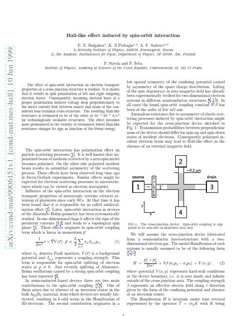
a r X i v :c o n d -m a t /9906151v 1 [c o n d -m a t .m e s -h a l l ] 10 J u n 1999Hall-like effect induced by spin-orbit interactionE.N.Bulgakov 1,K.N.Pichugin 1,2,A.F.Sadreev 1,21)Kirensky Institute of Physics,660036,Krasnoyarsk,Russia2)˚A bo Akademi,Institutionen f¨o r Fysik,Department of Physics,SF-20500,˚A bo,FinlandP.Stˇr eda and P.ˇSebaInstitute of Physics,Academy of Sciences of the Czech Republic,Cukrovarnick´a 10,16253PrahaThe effect of spin-orbit interaction on electron transportproperties of a cross-junction structure is studied.It is shown that it results in spin polarization of left and right outgoing electron waves.Consequently,incoming electron wave of a proper polarization induces voltage drop perpendicularly to the direct current flow between source and drain of the con-sidered four-terminal cross-structure.The resulting Hall-like resistance is estimated to be of the order of 10−3-10−2h/e 2for technologically available structures.The effect becomes more pronounced in the vicinity of resonances where Hall-like resistance changes its sign as function of the Fermi energy.The spin-orbit interaction has polarization effect on particle scattering processes [1].It is well known that un-polarized beam of nucleons scattered by a zero-spin nuclei becomes polarized.On the other side polarized incident beam results in azimuthal asymmetry of the scattering process.These effects have been observed long time ago in Stern-Gerlach experiments.Similar effects might be expected for electron scattering processes in microstruc-tures which can be viewed as electron waveguides.Influence of the spin-orbit interaction on the electron transport properties of mesoscopic systems attracts at-tention of physicists since early 80’s.At that time it has been found that it is responsible for so called antilocal-ization effect [2].Later,spin-orbit interaction in devices of the Aharonov-Bohm geometry has been systematically studied.In one-dimensional rings it affects the sign of the persistent currents [3,4]and leads to a topological spin phase [5].These effects originate in spin-orbit coupling term which is linear in momentump 12 µ,νσµβµ,νp ν,(1)where σµdenotes Pauli matrices,V ( r )is a background potential and βµ,νrepresents a coupling strength.This term is responsible for spin-orbit splitting of electron states at p =0.Just recently splitting of Aharonov-Bohm oscillations caused by a strong spin-orbit coupling has been reported [6].In semiconductor-based devices there are two main contributions to the spin-orbit coupling [7,8].One of them arises due to absence of an inversion centre in the bulk A III B V material,from which devices are usually fab-ricated,resulting in k -odd terms in the Hamiltonian of 3D-electrons.The second contribution originates in alow spatial symmetry of the confining potential caused by asymmetry of the space charge distribution.Lifting of the spin degeneracy in zero magnetic field has already been experimentally verified for two-dimensional electron systems in different semiconductor structures [9–11].In all cases the found spin-orbit coupling constant ¯h 2βhas been of the order of few mV ·nm.Anomalous resistance due to asymmetry of elastic scat-tering processes induced by spin-orbit interaction might be expected for the cross-junction device sketched in Fig.1.Transmission probabilities between perpendicular arms of the device should differ for spin-up and spin-down states of incident electrons.Consequently polarized in-cident electron beam may lead to Hall-like effect in the absence of an external magneticfield.FIG.1.The cross-junction device.Spin-orbit coupling is sup-posed to be non-zero in shadowed area only.We will assume the cross-junction device fabricated from a semiconductor heterostructure with a two-dimensional electron gas.The model Hamiltonian of such systems is usually assumed to be of the following form [5,12]H =p 2x +p 2ythe operator of complex conjugation.The spin matrix iσy acting upon the wavefunction of a state with well-defined value of the z-component of the spin,s z,changes the value of the z-component of the spin to its opposite,−s z[1].For the symmetrical cross-structure described by the Hamiltonian H there is additional inversion symmetry related to transformation x→−x and y→−y rep-resented by the operatorˆP x andˆP y,respectively.The Hamiltonian H,Eq.(2),commutes with operatorsσxˆP x andσyˆP y and transformed eigenfunctionsψ′(x,y)=σy P yψ(x,y),ψ′(x,y)=σx P xψ(x,y)(3) are thus eigenfunctions of the same Hamiltonian as well. Current and voltage contacts are modelled by huge electron reservoirs with negligible spin-orbit interaction. To simplify scattering boundary condition we have placed ideal leads with vanishing spin-orbit coupling,β≡0,be-tween electron reservoirs and studied cross-junction,as sketched in Fig.1.In these asymptotic regions electron wavefunctions can be expressed as linear combination of eigenfunctions of the straight infinite lead at given energy E.For each subband n they have form of a plane wave, e.g.for leads connecting reservoirs1and3we haveψ(x,y)= πw e±ik n x sinπny2,within given subbandn is forming its own quantum channel.Electron transport properties of a quantum device al-lowing elastic scattering only are fully determined by transition probabilities t i,j(n,s z→m,s′z)representing electron transition of the wave k n with spin s z approach-ing crossing via i-th lead into an outgoing channel-state (k m,s′z)within the lead j.The symmetry properties of the Hamiltonian H discussed above imply following use-ful identitiest1,2(n,s z→m,s′z)=t1,4(n,−s z→m,−s′z),t1,2(n,s z→m,−s z)=t1,2(n,−s z→m,s z),(5) t1,3(n,s z→m,s′z)=t1,3(n,−s z→m,−s′z).that remain valid for cyclic interchange of the lead num-bering.To obtain transition probabilities the following coupled equations for electron eigenfunctions have to be solved∂2u1∂y2+εu1+iα∂u2∂x=0,(6)∂u22∂y2+εu2+iα∂u1∂x=0,together with scattering boundary conditions discussedabove.Here we have introduced the following notationsψ≡ u1u2 ,ε=2m∗w2E2or-1outgoing waves can be partially polarized since the trans-mission into spin-up channels(T1↑,2↑+T1↓,2↑)differs from that into spin-down channels(T1↑,2↓+T1↓,2↓),as seen in Fig.2.Asymmetry of the scattering process also leads to the tendency of injected electrons to prefer left or right turn at the crossing in the dependence on their spin orienta-tion.To study this effect we have evaluated scattering coefficients T(↑)and T(↓)for the case of fully polarized incoming-waves defined as followsT(↑) L ≡T1↑,2↑+T1↑,2↓=T1↓,4↑+T1↓,4↓=T(↓)R,T(↑) S ≡T1↑,3↑+T1↑,3↓=T1↓,3↑+T1↓,3↓=T(↓)S,(8)T(↑) R ≡T1↑,4↑+T1↑,4↓=T1↓,2↑+T1↓,2↓=T(↓)L,R(↑)≡R i↑,i↑+R i↑,i↓=R i↓,i↑+R i↓,i↓=R(↓),Their energy dependence is shown in Fig.3.Other set of identities can be obtained by cyclic interchange of theFIG.3.Scattering coefficients T(↑)L ,T(↑)S,T(↑)Rand R(↑)for spin-up polarized electron wave injected from the source(lead1)as function of the energyε.Expected tendency of electrons with one particular spin orientation to prefer left or right turn is evident. Exceptions have been found in the vicinity of subband edges at energiesεn=π2n2.Sharp peak in the transmis-sion probabilities also appear at the energy of the second bound state(εb≈36.72)formed in cross structures[14]. It originates in a mixing of bound and transport states caused by spin-orbit interaction.It is similar effect as that induced by radiationfield[15].Under particular conditions the discussed spin depen-dent scattering could lead to a Hall-like effect.Current flow J applied alongˆx direction,i.e.from a source1to a drain3,could not only induce a voltage drop between source and drain,U ≡U1−U3,but there might also ap-pear a voltage drop in perpendicular direction,between voltage contacts2and4,U⊥≡U2−U4.Their relation can be expressed with the help of reflection coefficients R ii and transmission coefficients T ij representing elec-tron transition from the contact i to the contact j[16]. For the considered four terminal device we get U⊥=T12T34−T14T322.Spin-down electrons are supposed to be reflected by thefilter.Only injected spin-up electrons are thus allowed to reach the region betweenfilter and crossing denoted in Fig.1as1′.Those spin-up electrons that are reflected back by crossing into a spin-down channel are not allowed to leave region1′immediately.They are reflected byfilter and can try to escape from region1′again.The followed multiple-reflection process is con-by reflection coefficient R1↓,1↓.For transmission coefficients entering numerator of the right hand side of Eq.(9)we get:T12=T(↑)L+T(↓)L−γ1T(↓)L,T14=T(↑)R+T(↓)R−γ1T(↓)R,(10)T32=T(↑)R+T(↓)R+γ3T(↓)L,T34=T(↑)L+T(↓)L+γ3T(↓)R.γi represent effect of thefilter and they have following form1=T(↓)R+T(↓)S+T(↓)LN−R1↓,1↓.(11)simplicity we have assumed that there is no spin-flip associated with reflections at thefilter boundary.have also neglected any interference effects due to scattering processes in the region1’betweenfil-ter and crossing assuming an inelastic equilibration pro-cesses in thefilter vicinity leading to equal occupation of spin-down channels.Inserting expressions for scattering coefficients R ii and T ij into Eq.(9)and making use of the symmetry relations, Eq.(7)and Eq.(8),we getU⊥=1N−R1↓,1↓−1T(↑)R+2T(↑)S+T(↑)LU .(12)The voltage U⊥is proportional to the difference T(↑)L−T(↑)R≡T(↓)R−T(↓)Lsimilarly as in the case of the standard Hall resistance[16].Because of the spin-orbit coupling this difference might be non-zero as can be seen in Fig.3. Without presence of the polarizationfilter no perpendic-ular voltage drop arises as can be easily shown by assign-ing zero values to the coefficientsγi.To obtain Hall-like resistance R⊥=U⊥/J all other scattering coefficientshave to be evaluated.The numerical results for the pa-rameters already used to evaluate partial transmissionparent for electron waves polarized along ˆz direction (full line)and along ˆx direction (dotted line)as function of the energy.Two other types of polarization filters have also be considered.We have found that no Hall-like resistance appears if polarization filter is transparent for waves po-larized along ˆy direction.On the other side the filter which is transparent for electron waves polarized along the current direction,ˆx direction,Hall-like resistance be-comes even larger as shown in Fig.4.In the vicinity of bound states and subband edges the Hall-like effect become stronger and changes its sign.It indicates that there appear circulating currents in the crossing region changing their orientation with energy.Their origin in the vicinity of the second bound state with energy εb ≈36.72is understandable.Due to spin-orbit coupling this state is splitted into two states with opposite orbital momentum similarly like in devices of the Aharonov-Bohm geometry [3,4].Splitting of sub-band edges has similar effect.However,for most energies perpendicular voltage appears due to deformed current lines within cross junction only.Results of the model calculation slightly depend on the position of the bound-aries between regions with turn on and turn offspin-orbit coupling.However,no qualitative changes have been ob-served.The obtained values of the Hall-like resistance are mea-surable.However,available real cross-junctions are of larger dimensions than that used in our calculation.For this reason we have calculated R ⊥till energies εfour times larger than that presented in Fig.4.As expected with increasing number of channels the effect decreases but R ⊥is still of the order 10−3h/e 2.Polarization fil-ters might be realized by a locally applied magnetic field across the cross-junction arm,e.g.making use of a ferro-magnetic top layer.Also a ferromagnetic injector [17]can be use to induce Hall-like voltage.Polarization effects inreal systems will be hardly so effective as supposed in our model calculation.Especially possible spin-flip processes the vicinity of spin reflecting boundaries or due to im-within device leads would partially suppress described Hall-like effect.Nevertheless,the asym-induced by spin-orbit coupling has been long time verified in particle scattering experiments and we be-that the discussed effects will be ones observed in as well.ACKNOWLEDGMENTSThis work was supported by the Grant Agency of the Republic under Grant No.202/98/0085and by the of Sciences of the Czech Republic under Grant A1048804.It has been also partially supported the INTAS-RFBR Grant 95-IN-RU-657,RFFI Grant Krasnoyarsk Science Foundation Grant No.and by the ”Foundation for Theoretical Physics”Slemeno,Czech Republic.Authors acknowledge sim-discussions with Pavel Exner.。
(武汉大学)分子生物学考研名词汇总

(武汉大学)分子生物学考研名词汇总●base flipping 碱基翻出●denaturation 变性DNA双链的氢键断裂,最后完全变成单链的过程●renaturation 复性热变性的DNA经缓慢冷却,从单链恢复成双链的过程●hybridization 杂交●hyperchromicity 增色效应●ribozyme 核酶一类具有催化活性的RNA分子,通过催化靶位点RNA链中磷酸二酯键的断裂,特异性地剪切底物RNA分子,从而阻断基因的表达●homolog 同源染色体●transposable element 转座因子●transposition 转座遗传信息从一个基因座转移至另一个基因座的现象成为基因转座,是由转座因子介导的遗传物质重排●kinetochore 动粒●telomerase 端粒酶●histone chaperone 组蛋白伴侣●proofreading 校正阅读●polymerase switching 聚合酶转换●replication folk 复制叉刚分开的模板链与双链DNA的连接区●leading strand 前导链在DNA复制过程中,与复制叉运动方向相同,以5’-3’方向连续合成的链被称为前导链●lagging strand 后随链在DNA复制过程中,与复制叉运动方向相反的,不连续延伸的DNA链被称为后随链●Okazaki fragment 冈崎片段●primase 引物酶依赖于DNA的RNA聚合酶,其功能是在DNA复制过程中合成RNA引物●primer 引物是指一段较短的单链RNA或DNA,它能与DNA的一条链配对提供游离的3’-OH末端以作为DNA聚合酶合成脱氧核苷酸链的起始点●DNA helicase DNA解旋酶●single-strand DNA binding protein, SSB 单链DNA结合蛋白●cooperative binding 协同结合●sliding DNA clamp DNA滑动夹●sliding clamp loader 滑动夹装载器●replisome 复制体●replicon 复制子单独复制的一个DNA单元称为一个复制子,一个复制子在一个细胞周期内仅复制一次●replicator 复制器●initiator protein 起始子蛋白●end replication problem 末端复制问题●homologous recombination 同源重组●strand invasion 链侵入●Holliday junction Holliday联结体●branch migration 分支移位●joint molecule 连接分子●synthesis-dependent strand annealing, SDSA 合成依赖性链退火●gene conversion 基因转变●conservative site-specific recombination, CSSR 保守性位点特异性重组●recombination site 重组位点●recombinase recognition sequence 重组酶识别序列●crossover region 交换区●serine recombinase 丝氨酸重组酶●tyrosine recombinase 酪氨酸重组酶●lysogenic state 溶原状态●lytic growth 裂解生长●transposon 转座子能够在没有序列相关性的情况下独立插入基因组新位点上的一段DNA序列,是存在与染色体DNA上可自主复制和位移的基本单位。
机械敏感性离子通道蛋白Piezo1在椎间盘髓核细胞中的表达及意义

机械敏感性离子通道蛋白Piezo1在椎间盘髓核细胞中的表达及意义【摘要】椎间盘是脊柱结构中的重要组成部分,其功能与脊柱间的缓冲和支撑密切相关。
Piezo1作为机械敏感性离子通道蛋白,在椎间盘髓核细胞中的表达具有重要意义。
研究表明Piezo1的表达与椎间盘退化相关,同时在髓核细胞中起着调节机制和生理意义。
Piezo1作为潜在治疗靶点具有广阔的前景。
本文从多个方面探讨了Piezo1在椎间盘髓核细胞中的功能和意义,并展望了未来研究方向和临床应用前景。
该研究对于理解椎间盘退化的机制,以及开发相关治疗手段具有重要意义。
【关键词】椎间盘、髓核细胞、机械敏感性离子通道蛋白Piezo1、表达、退化、功能、调控机制、生理意义、治疗靶点、重要性、未来研究、临床应用。
1. 引言1.1 椎间盘的结构和功能椎间盘是位于脊柱各个椎体之间的软骨结构,由纤维环和髓核组成。
纤维环主要由纤维软骨构成,其外周覆盖有一层富含神经末梢和血管的周围环。
髓核则是位于纤维环内部的软骨组织,主要由水和胶原纤维构成,具有良好的弹性和吸水性。
椎间盘的主要功能包括:缓冲冲击和吸收脊柱压力、维持脊柱的稳定性、保持颈椎、胸椎和腰椎之间的正常关节活动、减少运动时的摩擦力以及吸收和分布运动时产生的压力。
椎间盘的结构和功能对于保持脊柱的正常生理状态至关重要,任何对椎间盘的损伤或退化都可能导致脊椎疾病的发生和发展。
研究椎间盘的结构和功能具有重要的临床意义,有助于预防和治疗与椎间盘相关的疾病。
Piezo1在椎间盘髓核细胞中的表达和功能研究将为我们更深入地了解椎间盘的生理过程提供重要参考。
1.2 Piezo1在机械敏感性离子通道中的作用Piezo1是一种机械敏感性离子通道蛋白,主要通过感知机械刺激来调节细胞内钙离子通道的开启,参与细胞对外界机械力的感知和转导。
在细胞应激和损伤等情况下,Piezo1能够快速响应机械刺激,进而触发细胞内信号传导通路,调节细胞的生理功能。
Mapping of spin lifetimes to electronic states in n-type GaAs near the metal-insulator tran
a r X i v :0706.1884v 1 [c o n d -m a t .m t r l -s c i ] 13 J u n 2007APS/123-QEDMapping of spin lifetimes to electronic states in n -type GaAs near the metal-insulatortransitionL.Schreiber,M.Heidkamp,T.Rohleder,B.Beschoten,∗and G.G¨u ntherodtII.Physikalisches Institut,and Virtual Institute for Spin Electronics (ViSel),RWTH Aachen University,Templergraben 55,52056Aachen,Germany(Dated:February 1,2008)The longest spin lifetimes in bulk n -GaAs exceed 100ns for doping concentrations near the metal-insulator transition (J.M.Kikkawa,D.D.Awschalom,Phys.Rev.Lett.80,4313(1998)).The respective electronic states have yet not been identified.We therefore investigate the energy dependence of spin lifetimes in n -GaAs by time-resolved Kerr rotation.Spin lifetimes vary by three orders of magnitude as a function of energy when occupying donor and conduction band states.The longest spin lifetimes (>100ns)are assigned to delocalized donor band states,while conduction band states exhibit shorter spin lifetimes.The occupation of localized donor band states is identified by short spin lifetimes (∼300ps)and a distinct Overhauser shift due to dynamic nuclear polarization.PACS numbers:78.47.+p,78.55.Cr,85.75.-dWithin the framework of the emerging field of spin-tronics,the spin degree of freedom is exploited for infor-mation storage as well as processing and could serve as a qubit for quantum computation [1].Spin coherence and long spin lifetimes are a prerequisite for novel spintronic devices.Electron spins in Si-doped bulk n -GaAs drew at-tention,when long spin lifetimes T ∗2>100ns and coher-ence lengths larger than 100µm were determined using time-resolved Faraday rotation [2,3].Since then n -GaAs was used as a model system to investigate spin injectionand spin transport phenomena [4,5,6].The long T ∗2of bulk n -GaAs,however,is restricted to a doping concen-tration in the vicinity of the metal-insulator transition (MIT)and shortens dramatically towards both sides of the transition [2,7].Similar results in n -type GaN [8],and n -type Si [9]point to a universal phenomenon.How-ever,the respective electronic states yielding these long T ∗2near the MIT have not been identified so far.Various spin relaxation mechanisms have been consid-ered to explain the dependence of T ∗2on carrier concen-tration,temperature,and magnetic field B .The relevant relaxation mechanisms differ substantially for delocalized spins with,e.g.,the D’yakonov-Perel’(DP)dephasing mechanism [10,11,12,13],and for spins localized at im-purity sites with,e.g.,relaxation by hyperfine interaction [13,14,15].Concerning the electronic states of n -type semiconductors,the MIT was shown to occur within the donor band (DB)[16],which is separated from the con-duction band (CB).Near the Fermi level (E F ),the elec-tronic structure is governed by both doping induced dis-order and local Coulomb correlation.The former yields Anderson-localized states in the upper and lower donor band-tails,which are separated from extended states in the center by mobility edges [17].The latter may lead to a Coulomb gap U at E F [18].Both interactions yield a complex electronic structure with coexisting localized and delocalized DB states as well as CB states.Spin dephasing in n -GaAs has mostly been investigated forstates at E F [2,3].There is,however,no energy-resolvedstudy of T ∗2,which would allow to assign spin lifetimes to the respective electronic states of both the donor and the conduction band.We expect that this assignment helps to identify the dominant spin relaxation mechanisms in the vicinity of the MIT.In this Letter,we study the spin lifetime T ∗2of co-herent electron spin states in n -GaAs,which are opti-cally excited in both the donor and conduction band and probed by time-resolved Kerr rotation (TRKR)at 6K.Due to the coexistence of distinct electronic states,thesample is not characterized by a single T ∗2:T ∗2varies by three orders of magnitude as a function of photon en-ergy.The longest T ∗2values which may exceed 100ns are found for delocalized donor band states,while free con-duction band states exhibit shorter spin lifetimes.Our time-resolved Kerr signal shows up to three exponential decay regimes with different precession frequencies.The latter can change due to an additional nuclear magnetic field arising from dynamically polarized nuclei,when res-onantly pumping spins into localized DB states.Two (001)-oriented,500µm thick GaAs wafers with different Si-doping concentrations have been investi-gated:Sample A with a carrier concentration of (2.4±0.2)×1016cm −3is doped close to the MIT (critical car-rier concentration in Si:GaAs n c ∼=1.5×1016cm −3)[16].Reference sample B has a carrier concentration of (1.5±0.4)×1018cm −3and is therefore degenerated [18].We used two tuneable,mode-locked Ti:Al 2O 3lasers pro-viding ∼150fs optical pulses corresponding to a spectral width of ≈6nm at a repetition frequency of 80MHz.Electronic phase-locking of both lasers enables us to em-ploy one laser for spin pumping at an energy E pu and the other one for probing the spin orientation at an en-ergy E pr after a variable delay time ∆t =0...16ns.The normal-incident pump pulses,which were circularly po-larized by a photo-elastic modulator (PEM),excite spin-polarized electrons and holes oriented along the beam2∆t (ps)θ∆t (ps)∆t (ps)sample Bsample A2.00-0.8θK (arb. units)7.60-5.3θK (arb. units)FIG.1:(Color)Time-resolved Kerr rotation for photon en-ergies E =E pu =E pr at 6K with (a)θK (∆t )for sample A at B =1T;the red line shows the shift of the beating node;(b)θK (∆t,E )for sample A at B =1T;(c)θK (∆t,E )for the degenerate sample B at B =6T.Arrows mark the respective energies,above which the transmission drops below 5%.direction in the strain-free mounted samples with an av-erage power P =50W/cm 2.The projection of the pump induced spin magnetization onto the surface nor-mal of the sample is determined with linearly polarized laser pulses by Faraday rotation θF in transmission and by Kerr rotation θK in reflection.Transverse magnetic fields B are applied in the plane of the sample.In Figure 1(a),we plot θK (∆t )of sample A measured for various photon energies E =E pu =E pr at B =1T and at T =6K.Obviously,the spins precess at all energies E ,but the damping of the oscillations andthus T ∗2is E -dependent:for E below the CB edge T ∗2is long,whereas for the highest E ,at which CB states arepumped,T ∗2is much reduced.Strikingly,a node in the oscillation envelope (red line in Fig.1(a))near the band edge indicates that the spins precess with at least two Larmor frequencies ω(i ).Therefore,θK (∆t )is described by n decay componentsθK (∆t )=n iA (i )exp−∆t3 constant and exhibits|g∗|=|g0|=0.43.Near the CBedge(green),B-independent values of T∗2∼100...300psare determined,which distinguish themselves by a rapiddecrease ofω(E).At the beginning of the third region(blue),T∗2sets-in at∼6ns and decreases with increasingE.The correspondingωdecreases slightly and saturatesat high E.The overlap in energy of the second and thirdregion,which occurs due to the spectral width of thelaser pulses,generates the node in the oscillation enve-lope shown in Figure1[19].For the degenerate sample B,T∗(i) 2(E)can befitted by one component i.As expected[2,7],T∗2is over-all shorter compared to sample A and T∗2increases with the increase of B,which is typical for the DP dephasing mechanism[10].In the following,we assign the T∗(i)2of the spins ob-served in the three energy ranges to carriers occupying different electronic states.Since hole spins relax quickly 10ps in GaAs and excitons are broken up at high magneticfields B 1T[20],we consider single elec-tron states.Since the carrier concentration of sample A is slightly above n c,E F lies within the delocalized DB states as sketched in Figure3.Thus delocalized DB states are pumped at lowest E,which exhibit the longest T∗2(red component in Fig.2).However,to our knowl-edge there is no relaxation mechanism of spins,which accounts for their distinct B-dependence.We assign the second energy range(green),which is missing for the degenerate sample B,to Anderson localized electronic states at the DB tail.Their distinct E-dependence of ωand T∗2can be linked to the decrease of localization length upon approaching the DB tail.The localization of electrons yields spin relaxation due to hyperfine inter-action with the nuclei[14,15].This gives rise to dynamic nuclear polarization and a nuclearfield,which altersω(Overhauser shift)[21].However,from Ref.[14]long T∗2∼300ns are expected for localized electron spins, although we could not reproduce this result with insu-lating n-GaAs samples using TRKR.In Ref.[15],an additional short T∗2∼100ps component is predicted, when both localized and delocalized spins are pumped. This is assigned to their cross-relaxation rate.Whereas this might explain our short T∗2,it does not account for the distinctω(E)dependence.In the third energy regime (blue),electrons are pumped in the CB.The decrease of ωobserved for both samples is due to g∗:The absorption of the pump pulse lifts the local chemical potential,thus reducing the absolute value of the energetically averaged g∗factor according to its dispersion in the CB[20].The apparent decrease of T∗2(E)might be explained by car-rier cooling and interband relaxation.Due to both,the carriers relax below the probed energy.This notion can be confirmed by sweeping E pu with E pr heldfixed at the bottom of the CB.The corre-spondingfits of T∗(i)2(E pu)andω(i)(E pu)of sample Aat B=1T are shown in Figure3(a)and(b).Indeed,pr23452345E (eV)E (eV)T(i)2*(ps)T(i)2*(ps)ω(i)/ω0FIG.3:(Color)Upper left:sketch of density of DB and CBstates.Fitted spin lifetimes T∗(i)2and Larmor frequenciesω(i) as a function of pump laser energy E pu at magneticfields B for MIT sample A(full symbols)for different probe energies E pr is marked with vertical grey lines.For comparison data from Fig.2with E pu=E pr are also plotted(open symbols).this method allows to correct T∗2for energy relaxation, since T∗2(E pu)(blue full symbols)decreases only slightly compared to Figure2.However,there is an additionalshort T∗(i)2(E pu)(green full symbols),which results from probing localized spins at the DB tail because of the spec-tral width of the probe pulses.To clarify this point, E pr isfixed at an energy even lower than the band gap(Fig.3(c)-(e)).For this E pr,the longest T∗(i)2(E pu)(red) attributed to delocalized DB states is observed,which turned out to be nearly constant at B=0T.Note that the average pump power is held constant,but the excited carrier density changes by orders of magnitude in the ab-sorbing regime.This has a negligible effect on the longest T∗2.More strikingly,additional components i become ob-servable,when E pu passes the localized and CB states. Thus,different electronic states become occupied either due to direct optical excitation or carrier relaxation as sketched in Figure3(upper left).From the onset of the θF signal(not shown),we deduce that the delocalized DB states are occupied within∆t<10ps for all E pu. At B=1T(Fig.3(d))and E pu beyond the band edge,the two long T∗(i)2components(blue and red)generate nodes in the oscillation envelope(Fig.1(a))and can be separated by theirω(i)(Fig.3(e)).Forfitting,however, the longest T∗2(red)of delocalized DB had to befixed with minor influence on the blue component.The lat-4∆t (ns)FIG.4:(Color)Faraday rotationθF(∆t)of sample A for left(σ−)and right(σ+)circularly polarized pump pulses(red ar-rows)at B=1T,E pu=1.514eV and E pr=1.494eV.Inset:fitted normalized Larmor frequenciesω(i)and correspondinglateral nuclear magneticfields BN for both polarizations as afunction of the average pump power.ter can be clearly assigned to CB states by comparing it to T∗2(E pu)and g∗(E pu)of Figure3(a)and(b).The existence of three components i and their onset whensweeping E pu confirms our assignment of T∗(i)2(E)to thethree types of electronic states.Since an optically pumped spin imbalance of localized electrons leads to pronounced dynamic nuclear polariza-tion(DNP)[21],wefinally check our assignment of elec-tronic states to T∗2by identifying DNP.When resonantly exciting localized spins at,e.g.,E pu=1.514eV,then DNP is optically observed by the Overhauser shift.This shift results in a change ofωdue to the presence of a lateral nuclear magneticfield B N adding up to B.Since spins exhibiting long T∗2are most sensitive to this shift, we chose the same E pr as in Figure3(c)-(e).In order to generate a well-defined longitudinally pumped spin com-ponent and thus to control the direction of B N with re-spect to B,we replaced the PEM by a quarter-waveplate and rotated sample A as sketched in Figure4[22].In this geometry,θF(∆t)exhibits nodes in the oscillation envelope at long∆t,proving the presence of two longT∗(i) 2components with differentω(i).The dependence ofωon the type of circularly polarizationσ±of the pump pulses,is clarified by thefittedω(i)in the inset of Fig-ure4.The sign and magnitude of B N is determined by σ±and the pump power,respectively.B N saturates for σ+at-90mT,when|g∗|=0.43is assumed to be con-stant.However,the blue component,which is likely due to spins in the CB(cp.to Fig.3(e)),is more sensitive to B N than the spins attributed to delocalized DB states (red).However,this point needs further investigation. Since DNP is not observable when E pu is reduced below 1.5eV,our assignment of localized states is confirmed. The pronouncedω(loc)(E)dependence of the localized spins(green)(see Fig.2left)compared to theωvari-ation(blue)in the inset of Figure4suggests that the ω(loc)(E)is indeed influenced by increasing localization and thus responsible for a rise of B N at the DB tail[23]. In summary,we have studied the energy dependence of spin lifetimes in n-type GaAs for electron doping near the metal-insulator transition.Distinct spin lifetimes have been assigned to both donor and conduction band states. Spin states at the Fermi level are delocalized donor band states with the longest spin lifetime,which may exceed 100ns.The strong decrease of spin lifetimes in the con-duction band is related to energy relaxation of hot elec-trons.Localized donor band states exhibit the shortest spin lifetimes of∼300ps.Resonant optical pumping of these localized states yields strong dynamic nuclear po-larization.This work was supported by BMBF and by HGF.∗Electronic address:beschoten@physik.rwth-aachen.de [1]D.D.Awschalom and M.E.Flatte,Nature Phys.3,153(2007).[2]J.M.Kikkawa and D.D.Awschalom,Phys.Rev.Lett.80,4313(1998).[3]J.M.Kikkawa and D.D.Awschalom,Nature397,139(1999).[4]Y.Kato et al.,Science306,1910(2004).[5]S.A.Crooker et al.,Science309,2191(2005).[6]X.Lou et al.,Nature Phys.3,197(2007).[7]R.I.Dzhioev et al.,Phys.Rev.B66,245204(2002).[8]B.Beschoten et al.,Phys.Rev.B63,121202R(2001).[9]V.Zarifis and T.G.Castner,Phys.Rev.B36,6198(1987).[10]J.Fabian and S.D.Sarma,J.Vac.Sci.Technol.B17,1708(1999).[11]P.H.Song and K.W.Kim,Phys.Rev.B66,035207(2002).[12]Z.G.Yu et al.,Phys.Rev.B71,245312(2005).[13]B.I.Shklovskii,Phys.Rev.B73,193201(2006).[14]R.I.Dzhioev et al.,JETP Lett.74,200(2001).[15]W.O.Putikka and R.Joynt,Phys.Rev.B70,113201(2004).[16]D.Romero et al.,Phys.Rev.B42,3179(1990).[17]P.Anderson,Phys.Rev.189,1492(1958).[18]A.Efros and M.Pollak,eds.,Electron-Electron Interac-tion in Disordered Systems(North-Holland,Amsterdam, 1984).[19]The third region sets in at even lower energy E≈1.514eV,where T∗2cannot be determined exactly dueto the beating.[20]M.Oestreich et al.,Phys.Rev.B53,7911(1996).[21]D.Paget et al.,Phys.Rev.B15,5780(1977).[22]G.Salis et al.,Phys.Rev.B64,195304(2001).[23]Even with the PEM,ωchanges whithin∼1min afterswitching on the pump.We attribute this to an Over-hauser shift.。
- 1、下载文档前请自行甄别文档内容的完整性,平台不提供额外的编辑、内容补充、找答案等附加服务。
- 2、"仅部分预览"的文档,不可在线预览部分如存在完整性等问题,可反馈申请退款(可完整预览的文档不适用该条件!)。
- 3、如文档侵犯您的权益,请联系客服反馈,我们会尽快为您处理(人工客服工作时间:9:00-18:30)。
a r X i v :c o n d -m a t /0401171v 1 12 J a n 2004Spin Transport in Two Dimensional Hopping SystemsT.Damker ∗and H.B¨o ttgerInstitute for Theoretical Physics,Otto-von-Guericke-University,PF 4120,D-39016Magdeburg,Germany V.V.BryksinA.F.Ioffe Physical-Technical Institute,Politeknicheskaya 26,19526St.Petersburg,Russia(Dated:February 2,2008)A two dimensional hopping system with Rashba spin-orbit interaction is considered.Our maininterest is concerned with the evolution of the spin degree of freedom of the electrons.We derive therate equations governing the evolution of the charge density and spin polarization of this system inthe Markovian limit in one-particle approximation.If only two-site hopping events are taken intoaccount,the evolution of the charge density and of the spin polarization is found to be decoupled.A critical electric field is found,above which oscillations are superimposed on the temporal decayof the total polarization.A coupling between charge density and spin polarization occurs on thelevel of three-site hopping events.The coupling terms are identified as the anomalous Hall effectand the recently proposed spin Hall effect.Thus,an unpolarized charge current through a sheet offinite width leads to a transversal spin accumulation in our model system.I.INTRODUCTION The emerging field of spintronics tries to put the spin degree of freedom of electrons to use in a fashion akin to electronics,where the charge of the electrons is utilized.1,2One of the advantages of spintronics is,that spatial inhomogeneities of the spin distribution are not burdened with an energetic penalty,quite in contrast to inhomogeneous charge distributions.On the other hand,spin is not conserved,whereas charge is.This is a disadvantage of spintronics,which means that spin polarization normally decays with time.Of special interest are techniques which influence the spin by purely electrical means,without utilizing magnetic fields or magnetic materials.Spin-orbit interaction (SOI)provides such a mechanism.In recent years much has been done in this field for itinerant electrons,favoring very clean samples of high mobility.3This investigation,on the other hand,studies the behavior of spins in a hopping system.Here,mobilities are very low,either through disorder (Anderson localization),or through strong electron-phonon interaction (polaron formation).Transport is thermally activated and incoherent.In the absence of effective spin scattering mechanisms,the low mobility might lead to long spin coherence times for a given spin coherence length,which is one motivation for this study,apart from the intrinsic scientific interest of the question of spin behavior in hopping systems.Previous studies of SOI in hopping systems centered on the influence of the spin dynamics on charge transport (e.g.magneto-conductance 4,5,6,7,8,9,10),not on the spin dynamics itself.Furthermore,the effective spin coupling between hopping sites has normally been taken to be random,8,9,11,12,13,14which is appropriate for spin scattering on charged impurities,but not for SOI due to intrinsic or external electric fields which are constant over length scales of several hopping lengths.But such a mechanism would be required if one has the intent of affecting the spins in a systematic way,i.e.realize spintronics.To be specific,we consider a system where the spin dynamics is solely determined by spin-orbit interaction through the Rashba-mechanism 15,16,17,18and no other spin scattering occurs (e.g.no magnetic impurities or spin scattering on charged impurities).The electronic system is two-dimensional (2D)and —in order to calculate explicit expressions —assumed to be ordered (small polaronic system).The disordered system is expected to behave qualitatively similar,but its investigation must be delegated to future publications.Two prominent examples of the interplay between charge and spin transport are the anomalous Hall effect and the spin Hall effect:The observation that a spin polarized charge current leads to a transversal Hall voltage,even without an external magnetic field,is called the anomalous Hall effect (see e.g.Ref.19and references therein).The inverse effect,that,in materials showing the anomalous Hall effect,an unpolarized charge current leads to a transversal spin (but not charge!)current has been proposed by Hirsch 20,21,22and is called the spin Hall effect.Both of these effects will in the following be identified for our model system.This paper is organized in the following way:Section II is concerned with the question of how to include the Rashba SOI into the hopping formalism.In Section III the rate equations governing the evolution of the (1-particle)density matrix are derived.This is done by calculating the diagrams of second and third order (two-site hopping and three-site hopping)in the Konstantinov-Perel diagram technique in 1-particle approximation and applying the Markovian limit.The rate equations for the density matrix are transformed into rate equations for the particle density and the spin orientation,which is an equivalent representation,but much more lucid physically.It is found that two-site hoppingdoes not introduce a coupling between the equations for the particle(charge)density and the equations for the spin polarization.Three-site hopping processes introduce such a coupling and indeed lead to the anomalous Hall effect and the spin Hall effect for this hopping system.Sections IV and V give solutions of the rate equations for an ordered hopping system(i.e.a system of small polarons).First,bulk properties(i.e.no boundaries)are considered.A short account of the results of Sec.IV has been published in Ref.23.Then,in Sec.V,a strip offinite width is considered,which introduces boundary condition at the transversal edges.The stationary state with an unpolarized charge current shows spin accumulation at the boundaries,which is an expression of the spin-Hall effect.The appendices primarily deal with mathematical details.Appendix C considers the magneticfield due to spin accumulation as a possible means of detection of spin accumulation.II.RASHBA SPIN-ORBIT INTERACTION IN HOPPING SYSTEMSThefirst question which arises,is how to include the spin-orbit interaction(SOI)into the formalism of hopping transport.The Rashba Hamiltonian readsH=p2mσ·(K×p)+V(r),(1)where we introduce the quantity K=mαe z/¯h2,which(i)has the dimension of an inverse length,(ii)is perpendicular to the two-dimensional plane(unit vector e z),and(iii)the length of which signifies the Rashba SOI strengthα.The same expression Eq.(1)can be used for the generic SOI due to a spatially constantfield E,in which case K=e2m(p−¯hσ×K)2+V(r),(2)while ignoring an irrelevant constant energy offset.Thus,in principle,the Rashba SOI can be dealt with as a SU(2) gauge potential.Since the gauge potential is a constant,this would be quite trivial,were it not for the fact that SU(2) is non-Abelian.If the gauge were Abelian,a wave functionΨ(r)would be studded with the factor exp(iσ·(K×r)) in order to include SOI.Due to the non-Abelian nature,there are additional higher order contributions in K.Those can be neglected,provided K is sufficiently small.The Hamiltonian which we consider readsH= mσǫm a†mσa mσ+ mm′σσ′Jσ′σm′m a†m′σ′a mσ+H e−ph+H ph,(3) where H e−ph denotes the electron-phonon interaction and H ph is the Hamiltonian of the phonon system.Here,a†mσ(a mσ)is the creation(annihilation)operator of an electron at site m in spin stateσ,ǫm is the site energy,and Jσ′σm′m isthe resonance integral between the states mσand m′σ′.Without SOI,the resonance integral is diagonal in spin space and will be denoted as J m′m in the following.Note,that the usual spin splitting due to Rashba SOI is not manifesthere,since Kramer’s degeneracy demands,that the two spin states of a localized eigenstate have to be degenerate. The central question for the inclusion of SOI into the hopping Hamiltonian now consists in determining the spinstructure of Jσ′σm′m.The four numbers belonging to each pair of sites m′m are collected into a2×2-matrix in spin spaceˆJ m′m.ClearlyˆJ m′m→J m′mˆI2for K→0,whereˆI2denotes the two-dimensional unit matrix.Since the Hamiltonian has furthermore to be Hermitic and invariant under time-reversal symmetry,the spin structure is given by an SU(2)matrix,8,9,11,17,24,25,26,27ˆJ m′m=exp(−iσ·A m′m)J m′m,where all components of the vector A have to be real numbers and the condition A m′m=−A mm′must be obeyed.The arguments after Eq.(2)show that the term linear in K reads−iσ·(K×R m′m),where R m′m=R m′−R m is the distance vector between the sites,and R m is the coordinate vector of site m.Thus,ˆJm′m=e−iσ·(K×R m′m)J m′m,(4)For this expression forˆJ to be valid,K has to be sufficiently small,as explained in the paragraph after Eq.(2).In this case,this means,that the condition K×R m′m≪1must be valid for the distance vectors R m′m,which are relevant to the case at hand(e.g.the typical hopping length or the lattice constant).The same expression,but applied to the Green’s function of a hopping system,has been derived in Ref.4.In some sense,this is equivalent to the Holstein transformation,28where the influence of a magneticfield on a hopping system is taken into account through a phase factor,and where higher order(in the magneticfield)corrections are neglected.We are now prepared to derive rate equations governing the hopping system with the inclusion of Rashba SOI in the next section.III.RATE EQUATIONSWe apply the Konstantinov-Perel diagram technique in order to obtain rate equations for the density matrix.The off-diagonal elements of the(1-electron)density matrix a†m′σ′a mσ can usually be neglected in a hopping system (otherwise,the transport mechanism would not be hopping).Here,we have to keep in mind,that the correlations between different spin states on the same site contain information regarding the(expectation value of the)spin orientation.Furthermore,the model which we consider,aims at systems where the spin degrees of freedom do not de-cohere(lose their phase memory)while the electron stays on a site.Thus,we must retain the off-diagonal elements in spin space on the same site(i.e.diagonal in the site index)of the density matrix.In this way,by including the SOI the occupation probabilityρm= a†m a m becomes a2×2-matrixˆρm|σ′σ= a†mσ′a mσ in spin space.In order to adapt the Konstantinov-Perel diagram technique to the SOI case,each site index can be thought of as additionally containing the spin index.The summations run over all sites and also the two spin states.The electron-phonon interaction is unaffected by the spin state.Thus,the extension of the formalism reduces to(i)studding each site index with a spin index(and extending the corresponding sums)and(ii)allowing expectation values which are non-diagonal in spin space.The number of terms in a given diagram proliferates quite rapidly with the order of the diagram and makes its computation tedious.The calculations are greatly simplified,if one replaces the explicit summation over the spin indices by matrix multiplication in spin space.This can be achieved by collecting the interaction matrix elements J(which depend on two site and two spin indices)into appropriate matrices in spin spaceˆJm′m (which only depend on two site indices)and doing likewise with the density matrix elements.The second order diagrams(two-site hopping)yield in one-particle approximation and in the Markovian limit the rate equationsd2ρmˆI2+1dtρm= m1{ρm1W m1m−ρm W mm1}.(6)On the other hand,multiplying Eq.(5)byσand then taking the trace,one obtains the rate equation for the spin orientation(see Appendix A)dOnly the latter type of third order terms will be retained in the following calculations.The products of spin matrices occurring in the third order terms are calculated in Appendix A.The rate equations up to terms of order K2and neglecting superfluous terms as mentioned above readddtρm= m1 ˆD m1m·ρm1W m1m−ρm W mm1+ m1m2K·(R mm1×R mm2)◦K W R m1m2mρm1−W R mm1m2ρm− m1m2K·(R mm1×R mm2)◦K× W I m1m2mρm1−W I mm1m2ρm .(9) Eqs.(8)and(9)are the generic hopping rate equations for the model considered here(only Rashba SOI affectsspin).The transition rates W m′m,W R m1m2m ,and W I m1m2mare independent of spin and are determined by the type ofhopping considered(e.g.small polaron hopping or hopping between impurities).In the remaining part of the paper, we focus on an ordered(polaronic)system,but Eqs.(8)and(9)would also be the starting point for an investigation of a disordered system.Summing Eq.(8)over all sites m yields ddtρ(q)=[W(q)−W(0)]ρ(q)+ W R(q)−W R(0) ·ρ(q)(10) anddi∂∂q◦∂∂q·∂∂q×∂The basic transition rates areW(q)= m e i q·R m W0m(15)W RI(qq1)= m1m e i q·R m e i q1·R m1W RI0m1m(16) In an isotropic system,taking the long wavelength limit,they readW(q)=W(0)−D q2−iµq·E(17) andW RI(q)=i K◦q·(E×K)W RI,(18) the latter being calculated for a triangular lattice(see Appendix B).Here,D is the diffusion constant,µthe mobility, and the quantities W R and W I are constants defined through Eq.(B8).The rate equations thus take the shapeddtρ(q)=−i q·ˆJ(q)+Q(q)(21) with the(tensorial)spin current densityˆJ(q)=µE◦ρ(q)−i D q◦ρ(q)+4DˆI3K·ρ(q)−4Dρ(q)◦K+W R K×E◦Kρ(q)−W I K×E◦K×ρ(q)(22) and the spin source densityQ(q)=−4D K2ρ(q)−4D K◦K·ρ(q)+2µ(K×E)×ρ(q)(23) Eq.(19)is the continuity equation for the particle(charge)density.Eq.(21)contains a source term in addition to the divergence of the current,since there is no conservation law for spin.Thefirst two terms contributing to the charge current(20)are the drift term in the electricalfield and the diffusion.The third term only occurs,when there is afinite z-component of the polarization(i.e.a magnetization M z).The resulting current is directed perpendicular to the electricfield.Thus,this term corresponds to the anomalous Hall effect.The corresponding mobility is seen to beµyx=W R K2.The quantityµyx/µis related to the Hall mobility(see Appendix B).The spin current Eq.(22)mainly consists of the drift term and some diffusion terms.But the most interesting contribution is thefifth term on the right-hand side,since it is also present for vanishing spin polarizationρ=0. This term describes a current of z-spins into the direction perpendicular to the electricfield(K×E).Thus,it is an expression of the spin Hall effect.The co-efficient W R is the same,as the one responsible for the anomalous Hall effect.In order to simplify notation,dimensionless quantities are introduced:dimensionless space x=K r,wave vector ξ=q/K,timeτ=DK2t and electricfieldǫ=µE/(DK).The transformed third order probabilities are denotedasǫR=KED W I.Note,thatǫR can be expressed asµyxǫ/µ.Thus,ǫR is an analog of the Hallmobility multiplied by the electricalfield.Furthermore,the co-ordinate system isfixed such,that e z∝K,e x∝E, and e y∝K×E.Then K=K e z and E=E e x.This transforms the rate equations(19)and(21)todddτρ(0,τ)=0(26)ddτρx=−4ρx+2ǫρz(28a)ddτρz=−8ρz−2ǫρx,(28c) the solution of which isρx(τ)=e−6τ ρx(0)cosh(2τ √1−ǫ2) (29a)ρy(τ)=e−4τρy(0)(29b)ρz(τ)=e−6τ ρz(0)cosh(2τ √1−ǫ2) .(29c)ρx(0),ρy(0),andρz(0)are the initial conditions.Note,that there is a critical electricalfield strengthǫc=1.In smallerfields the total spin polarization decays exponentially with time,but in largerfields,it additionally rotates with time.This critical electricfield E c=DK/µcan also be expressed as E c=k B T K/e,provided the Einstein relation between D andµis valid.Furthermore,without electricfield,the z-component of the total spin polarization decays twice as fast as the other two components.23,29Taking for definiteness the initial conditionρ(0)=e z,one obtainsρx(τ)=e−6τǫ1−ǫ2sinh(2τ1−ǫ2)−11−ǫ2sinh(2τρx (τ)=e −6τǫǫ2−1sin(2τ √ǫ2−1+φ),(31c)with sin φ=1/ǫ.Note,that the frequency of the polarization oscillation 2√ǫ2−1/ǫand z =ρz e 6τ√τ(Largedistances will not be relevant here,since they are strongly suppressed by the “diffusion factor”exp(−x 2/4τ).)isρz (x ,τ)=exp −(x +ǫτ)24τ 3πτJ 0 √2|x | (32)Note,that in this approximation (long times and short distances),the sign of the polarization —determined by the argument of the Bessel function J 0—only depends on the distance to the origin,and is furthermore not time dependent.This spatial oscillation is due to the precession terms in the rate equations.The exponential factor exhibits a decay term with (dimensionless)time constant 4/7and a drift-diffusion term with drift velocity −ǫand diffusion constant 1.V.STRIP OF FINITE WIDTHThe distinguishing feature of a strip of finite width is,that there is no current (neither charge,nor spin)across the transversal boundaries.Thus,the spin-Hall current must be compensated by a diffusion current,i.e.a finite spin density can be expected to occur near the boundary.Indeed,the following will show,that a transversal spin accumulation will occur in this situation.For a broad strip,the non-zero spin density is mainly constricted to near the boundaries.The strip is oriented,so that the x -direction is along the length of the strip (the direction of thecurrent flow),the y -direction is along the width of the strip and the z -direction is perpendicular to the 2D strip (see Fig.1).The strip extends from y =−b to y =b ,thus,its width is 2b .Going from wave-vector space back to x -space and assuming that ρ(x )and ρ(x )=(ρx ,ρy ,ρz )depend only on the y -coordinate,the following set of differential equations determine the stationary stateρ′′+ǫR ρ′z =0(33a)ρ′′x +ǫI ρ′y +2ǫρz −4ρx =0(33b)ρ′′y −ǫI ρ′x +4ρ′z −4ρy =0(33c)ρ′′z +ǫR ρ′−4ρ′y −2ǫρx −8ρz =0(33d)where the prime denotes the derivation with respect to y .The boundary conditions at y =±b are obtained by equating the normal component of the currents (20)and (22)at the boundary to zero.This yields(ρ′+ǫR ρz )|y =±b =0(34a)(ρ′x +ǫI ρy )|y =±b =0(34b)(ρ′y −ǫI ρx +4ρz )|y =±b =0(34c)(ρ′z +ǫR ρ−4ρy )|y =±b =0.(34d)One has to keep in mind,that we want the solution to lowest order in K .The zero-th order solution of Eqs.(33a)to (34d)is obtained by removing all terms at least linear in K ,i.e.setting ǫI =0and ǫR =0.This immediately yields the solution ρ(y )=const .and ρ(y )=0.This solution is inserted into the terms containing ǫR and ǫI ,which yields the equations for the first order solutionρ′′=0(35a)ρ′′x +2ǫρz −4ρx =0(35b)ρ′′y +4ρ′z −4ρy =0(35c)ρ′′z −4ρ′y −2ǫρx −8ρz =0(35d)with the boundary conditions(ρ′)|y =±b =0(36a)(ρ′x )|y =±b =0(36b)(ρ′y +4ρz )|y =±b =0(36c)(ρ′z −4ρy )|y =±b =ǫR ρ.(36d)The solution of this set of equations can easily be constructed,since the only difference to the equations of zero-th order is the finite right-hand side in the boundary condition (36d).Again,ρ(y )=const .,and the 3vectorial ρ-components are weighted sums of functions sinh(λy )and cosh(λy)where λtakes on the three values:λ1=2,λ2= ǫ2+7= 8+ǫ2−1+i 8+ǫ2+1and λ3= ǫ2+7=λ∗2.Thus,to lowest order in K ,ρx (y )αλ2c 2s 3sinh(2y )+2ǫ2λ3s 1c 3 sinh(λ2y )+c.c.(37a)ρy (y )αλ2c 2s 3cosh(2y )+4λ22λ3s 1c 3 cosh(λ2y )+c.c.(37b)ρz (y )α16c 1s 3+ǫ22|λ2|2λ2s 1c 3+16(λ22+12+ǫ2)c 1s 3 −c.c.(38)and c i =cosh(λi b ),s i =sinh(λi b )(i =1,2,3).(39)One can see,that the electron density ρand the spin Hall co-efficient ǫR only influence the amplitude of the po-larization.They do not affect the spatial dependence of ρ(y ).The x -and z -component of the polarization are anti-symmetric with respect to a sign change of y ,whereas the y -component is symmetric.For a large electric field ǫ≫1ρx (y )≈−sgn(y )ǫR ρ2ǫsin √4 e −√ǫsin √ǫ(b −|y |)(40b)ρz (y )≈−sgn(y )ǫR ρ2ǫcos √4 e −√ǫ=√ǫ).For b ≫1(i.e.in natural units:width ≫K −1)the spin polarization is significant only near the boundaries due to the hyperbolic functions.This suggests that there is a “spin diffusion length”governing the spatial extent of non-zero ρnear the borders.This suggestion can be fleshed out in the following way:We consider the half plane y ≥0,set theelectric field ǫto zero and apply the boundary condition ρ(y =0)=ρ0.The differential equations for the stationary state (and homogeneous in x )areρ′′x −4ρx =0,ρ′′y +4ρ′z −4ρy =0,ρ′′z −4ρ′y −8ρz =0,(41)which conceptually corresponds to an equation with the structure D ∆ρ−ρ/τ=0,only that here the decay rate 1/τdepends on the direction (thus,it is a tensor),and there is an additional “torque”term.Since in Eq.(41)all co-efficients are numbers (in dimensionless units)the resulting “spin diffusion length”√√so strong,that the spatial oscillations of the spin orientation survive the averaging over the whole volume,so that they appear as temporal oscillations.Without an electricfield,the decay of an initial spin orientation is found to behave anisotropic:The z-component (perpendicular to the plane)decays twice as fast as the in-plane components.The inclusion of three-site hopping terms leads to the occurrence of a transport co-efficient(ǫR orµyx)which provides a coupling between charge and spin transport.A spin current produces a transversal charge current(anomalous Hall effect),and a charge current produces a transversal spin current(spin Hall effect).In a two-dimensional strip offinite width,this transversal spin current manifests itself as a spin accumulation at the boundaries of the strip.Finally,some remarks about the experimental relevance are in order here.The Rashba SOI strength is widely given as being of the orderα≈10−9eV cm.4,18It is possible to change this value by applying a gate voltage to the two-dimensional plane30,where a variation by at least50%has been shown to be realizable.This might be conceptually favorable for the implementation of spintronics devices,where electric means to control spins are sought. Using the value ofαmentioned above,one obtains K≈1/(76˚A),assuming that the effective electron mass is equal to its elementary mass.Thus,the condition K×R m′m≪1for the validity of our theory demands in this case,that the typical hopping length is shorter than76˚A.This value is conveniently large,so that the range of polaronic nearest neighbor hopping is well within the validity range.But impurity hopping or variable range hopping are also not out of the question.Furthermore,for a smaller Rashba co-efficient,the permitted length increases and it is furthermore modified by the effective electron mass.If the Einstein relation between diffusion co-efficient and mobility is assumed to be valid,the critical electricfield E c=k B T K/e for the oscillatory behavior of the total spin polarization is estimated to be about104V/cm at a temperature of100K.The calculations in Appendix B show a close connection between Hall mobility and the co-efficient for the spin Hall effect.Thus,a large Hall mobility favors also the occurrence of the spin Hall effect.We take Ref.31as an example. There,the conductivity and the Hall mobility of the hexaboride compounds Eu1−x Ca x B6are measured,and the authors conclude,that the transport mechanism is polaron hopping(in a certain range of concentrations x and for high temperatures).The reported Hall mobility in the polaronic hopping regime is of the order of100cm2/(Vs). Using this value,Eq.(B12)gives the estimateµyx/µ≈0.23,i.e.the transversal mobility for the spin Hall effect is about a fourth of the longitudinal mobility.Taking Eq.(37c)into account,this gives a relative spin polarization (z-component)at the boundary of a two-dimensional strip|ρz(b)/ρ|of about5%at the critical electricfield strength ǫ=1.AcknowledgmentsThis work is in part supported by the DFG(Deutsche Forschungsgemeinschaft)under Grant No.436RUS 113/67/11-2.APPENDIX A:CALCULATION OF THE SPIN MATRICESApplying the identity(σ·A)(σ·B)=(A·B)+iσ·(A×B),valid for any vectors A and B,to the series expansion of the exponential function,one easily obtains the relationsin|A|e iσ·A=cos|A|+iσ·Athis expression only terms of up to second order in K(since A≪1),one obtainsˆDm1m=ˆI3+2|A|(e R◦e z−e z◦e R)−2|A|2(e z◦e z+e R◦e R),(A4) whereˆI3is the identity matrix in three dimensions.Note that det(ˆD)=1+O(A4),where O(x)is Landau’s big-O notation,i.e.that the length of the vectorρdoes not change(up to O(A4))due to the application of the operator ˆD.Omitting the A2-term,the length of the vector would change in second order of A;then,ˆD would not represent a rotation.The products of spin matrices in the three site diagrams are calculated using the following scheme:After rotating the operators within the trace,so thatˆρis the last operator,the spin factors precedingˆρin the trace are calculated in order to obtain an expression of the form f+gσ.Here,f and g are scalars in spin space.Thus,taking the trace yields Tr((f+gσ)ˆρ)=fρ+gρ,an expression where the spin operators have disappeared and are replaced by the particle density and the spin ing the operator identity e A e B≈e A+B e[A,B]/2,where the error is of third and higher order in the operators A and B,one obtainse−iσ·A mm2e−iσ·A m2m1≈e−iσ·A mm1e iσ·(A mm1×A mm2)(A5) ande−iσ·A mm2e−iσ·A m2m1e−iσ·A m1m≈e iσ·(A mm1×A mm2).(A6) Using Eqs.(A2),(A5),and(A6),which are all valid to second order in A(i.e.also in K),and Eq.(A1),the spin structure of the three-site terms can be calculated,e.g.Tr e−iσ·A mm2e−iσ·A m2m1e−iσ·A m1mˆρ ≈cos|A2|ρ+i sin|A2||A2|A2ρ−sin|A2|¯h3J mm2J m2m1J m1mI,(B2)where the symbol I denotes the integralI (E )=e−3S T∞−∞dt 1∞dt 2expqΓq2)+cos ωq (t 2+i¯hβ2) −1×expi¯h e E ·R mm 2t 2(B3)with the abbreviationsΓq =|γ(q )|2(1−cos q ·g )2coth(¯h ωqβk B TRe(W (3)012).(B8)In order to calculate W I the imaginary part of W (3)has to be used instead of the real part.The indices 0,1and 2denote the sites located at the vertices of an elementary triangle of the lattice.W (3)012has to be calculated in zero electric field.Thus,there only remains to determine the integral I (0)in order to obtain the third order coefficients.For a sufficiently large phonon dispersion,the main contribution to the integral I comes from a saddle point (t 1s ,t 2s )at (i2¯h β/3,i¯h β/2).Under the condition ¯h ωq ≪k B T (high temperatures compared with the Debye temperature),the exponent in the integrand can be expanded in a series in t 1and t 2,which is truncated after the second order terms.The integral can then be calculated and one obtainsI ≈¯h 2π3e−4E a3k B T 3k B T,(B9)whereE a =q¯h ωq Γq3πE a (k B T )2e−4E awhereµ0=ea2/¯h and a is the distance between nearest neighbors(lattice constant).This expression can be compared with the Hall mobilityµH for small polaron hopping32to give the relationµyxµ0=2¯h K2µH2π b−b dy′M y(y′)(y−y′)+M z(y′)z 4πbarctan 2az8πb log z2+(y−b)2FIG.1:The co-ordinate system chosen for the strip offinite width.The charge current within the strip is non-polarized.But at the transversal boundaries y=±b,afinite spin density occurs due toǫR,i.e.this situation leads to spin accumulation.FIG.2:The magneticfield due to the spin accumulation in the z-y-plane.The parameters are b=1,ǫ=1.The horizontal line denotes the extent of the strip.29O.Bleibaum(unpublished).30J.Nitta,T.Akazaki,H.Takayanagi,and T.Enoki,Phys.Rev.Lett.78,1335(1997).31J.-S.Rhyee,B.K.Cho,and H.-C.Ri,Phys.Rev.B67,125102(2003).32H.B¨o ttger and V.V.Bryksin,Hopping Conduction in Solids(Akademie-Verlag,Berlin,1985).33L.Friedman and T.Holstein,Ann.Phys.(N.Y.)21,494(1963).。