PS系列压力开关
流量开关、压力开关

出料端同步机侧(5FS)高压流量
出料端非同步机侧(6FS)高压流量
进料端
(7FS)小齿轮流量
进料端
(8FS)小齿轮流量
0.56GPM
进料端同步机侧(1PS)高压压力
进料端非同步机侧
(2PS)高压压力
400PSI
出料端同步机侧
(3PS)高压压力
400PSI
出料端非同步机侧
(4PS)高压压力
400PSI
进口压力
稀油站
出口压力
133.5Kpa
流量开关
700m3/min
3#
鼓风机
稀油站
进口压力
稀油站
出口压力
133.5Kpa
流量开关
700m3/min
4#
鼓风机
稀油站
进口压力
93.1Kpa
稀油站
出口压力
117.2Kpa
流量开关
700m3/min
5#
鼓风机
稀油站
进口压力
93.1Kpa
稀油站
出口压力
117.2Kpa
流量开关
700m3/min
6#
鼓风机
稀油站
进口压力
93.1Kpa
稀油站
出口压力
117.2Kpa
流量开关
700m3/min
进料端非同步机侧(8FS)高压流量
12GPM
进料端进口
(9FS)低压流量
9GPM
出料端进口
(10FS)低压流量
9GPM
进料端
(11FS)小齿轮流量
1GPM
出料端
(12FS)小齿轮流量
1GPM
出料端同步机侧(2PS)高压压力
真空压力开关解读
2) NPN 集电极开路输出 2 channels + 自动移位输入
3) PNP 集电极开路输出 2 channels + 模拟量输出 4) PNP 集电极开路输出 2 channels + 自动移位输入
4. Enclosure IP65
介质
输出信号
温度范围
o
温度特性
C
analog output : 1 to 5V (load impedance : min 10k) -10 to 70oC(point dew) within 1% F.S. within 5.5% F.S. within ±0.3% F.S IP65
(standard 25o C) -10 to 70 oC 重复精度 防护等级
GS40
具有压力开关功能的数字式压力表(0~10bar)
ZSP1
用于ZX真空发生器 适用于小口径吸管(Φ0.3~Φ1.2),吸取数mm厚的芯片部品
压力开关 PSE
采用密闭腔使压力传感器与介质完全隔离
压力开关 PSE
PSE5 2 1 - 01
Pressure range 0 High pressure (0 to 1MPa) Piping specification
* 1 Vacuum (0 to -101KPa)
01
02
R(PT)1/8,M50.8
R(PT)1/4,M50.8
T01 NPTF1/8,M50.8 T02 NPTF1/4,M50.8
压力开关 PSE521
型号 适用压力范围
最大压力
* PSE5210 to -0.1MPa
压力开关技术协议

项目压力开关技术协议买方:卖方:目录附件1 技术规范11 范围12 工程概况23 标准和规范24技术要求3附件2 供货范围5附件3 技术资料和交付进度7附件4 检验和性能验收试验8附件5 技术服务和设计联络9附件 6 包装与运输10附件1 技术规范1 范围1.1本协议适用于定货.它提出了该设备的功能设计、结构、性能、安装和试验等方面的技术要求.1.2本技术协议提出了最低限度的技术要求,并未对一切技术细节做出规定,也未充分引述有关标准和规范条文,卖方应保证提供符合本技术技术协议和工业标准的优质产品。
对国家有关安全等强制性标准,必须满足其要求。
1.3本技术协议所使用的标准如与卖方所执行的标准发生矛盾时,按较高标准执行。
1.4如卖方没有以书面形式对本技术协议的条文提出异议,那么,买方认为卖方提供出的产品完全满足本技术协议的要求。
1.5合同规定的文件,包括图纸、计算、说明、使用手册等,均应采用国际单位制(SI).1。
6只有买方有权修改本技术协议并负责解释.1。
7本技术协议为订货合同的附件,与合同正文具有同等效力。
1。
8设备采用的专利涉及到的全部费用均被认为已包含在设备报价中,卖方应保证买方不承担有关设备专利的一切责任。
1.9买方在设计过程中对于卖方供货清单的确认,并不代表买方将为仪表的设计、选型承担责任,卖方应完全保证所供仪表的安全可靠性、合理性、完整性和优良性。
无论是否经过买方确认,卖方都应无条件对设备中的缺陷、不足和与合同不符的地方进行修改、补充或更换,而不增加任何费用。
1。
10卖方应保证最终的型号可满足买方提出的工况要求,由卖方承担由于选型错误所造成的一切后果.1.11卖方提供的设计、设备资料及随机资料应采用中文进行表述,如有外文资料,必须提供中文译本,并以中文译本为准.所有文件、图纸及相互通讯,均需使用中文对照。
设备铭牌采用中文对照标注。
1。
12产品实行三包,设备保质期为设备验收合格后一年(168试运行结束开始)或到货后18个月(先到为准),在质保期内,设备若出现质量问题,卖方应给予免费维修或更换。
ps压力开关原理

ps压力开关原理PS压力开关原理一、引言PS压力开关是一种常用的电气元件,广泛应用于各种机械设备中,如空压机、水泵等。
它的作用是根据系统压力的变化来控制设备的启停,以保护设备的安全运行。
本文将围绕PS压力开关的原理展开详细介绍。
二、PS压力开关的基本结构PS压力开关主要由压力感应器、控制电路和输出装置组成。
其中,压力感应器用于感知系统的压力变化,并将其转化为电信号。
控制电路根据压力信号的大小,判断是否达到设定值,进而控制输出装置的状态。
三、PS压力开关的工作原理1. 压力感应器的工作原理压力感应器通常采用弹性元件(如弹簧)和敏感元件(如压力膜片)相结合的方式,通过受压后的形变来感知系统的压力变化。
当系统压力达到设定值时,弹性元件和敏感元件会产生相应的形变,从而改变电路中的参数(如电阻、电容等),进而产生电信号。
2. 控制电路的工作原理控制电路是PS压力开关的核心部分,它负责判断压力信号的大小,并根据设定值来控制输出装置的状态。
控制电路通常包括比较器、电阻网络和输出驱动电路等。
(1)比较器:比较器是控制电路的核心元件,它将压力信号转化为电压信号,并与设定值进行比较。
当压力信号大于设定值时,比较器输出高电平,反之输出低电平。
(2)电阻网络:电阻网络用于调节设定值,通常由可变电阻和固定电阻组成。
通过调节可变电阻的阻值,可以改变设定值,从而满足不同压力范围的需求。
(3)输出驱动电路:输出驱动电路根据比较器的输出信号,控制输出装置的状态。
当比较器输出高电平时,输出驱动电路闭合,使输出装置工作;反之,输出驱动电路断开,输出装置停止工作。
四、PS压力开关的应用场景PS压力开关广泛应用于各种机械设备中,主要用于以下几个方面:1. 空压机:PS压力开关用于感知空气压缩机的工作压力,当达到设定值时,控制空气压缩机的启停,以保护其正常运行。
2. 水泵:PS压力开关用于感知水泵系统的压力变化,当达到设定值时,控制水泵的启停,以保护水泵不因压力过高或过低而造成损坏。
SMC ps1000系列压力开关

PS1000系列
规格/型号
型号 应用 输出方式 使用流体 最大使用压力 设定压力范围 温度特性 重复精度 PS1000-R06L 正压用 供应压力≥设定压力:开 空气 1MPa -0.1 ~0.45MPa ±3%满刻度以下 ±1%满刻度以下 4%满刻度 DC12~24V(波动±10%以下) 5~40mA 1mA以下 5V以下 ON时红色指示灯亮 0~60℃(未结露) 电线与壳体之间2M‰(DC500V高阻表) 电线与壳体之间AC1000V 50/60Hz(1分钟) 10~500Hz宽度=1.5mm或加速度10G(选择最小震动)在X,Y,Z方向各2个小时 100G在X,Y,Z方向(每方向3次) ø6mm快换接头插管 直接出线式,防油乙烯基橡皮绝缘软电线,2线 ø2.55,0.18mm2导线长3m
世界最小、最轻的电子式压力开关 * 体积小:30L×13W×10H(mm) <标准型:不包括导线部份> * 2线式:NPN,PNP共用 * 安装方便:安装在快换接头上 * 开关结构:硅片扩散型半导体压力开关
迟滞 供应电源 消耗电流 漏电流 内部电压降
开关形式
压力 MPa 设定压力
指示灯 使用温度范围 绝缘 耐电压 设定压力 以上:开 设定压力 以下:开 耐震动 耐冲击主回路 开关 主回路
连接例
茶(红) NPN 应用 茶(红)输入 茶(红)输入 PNP 应用
蓝(黑)
负载
蓝(黑)
蓝(黑)
蓝(黑)
用途例
气源压力的确认
压力开关
外形尺寸图 (毫米)
检定气缸使用压力 气缸
F.R.L. 空气过滤组合元件
压力设定旋钮 LED显示部分 压力开关 电磁阀 真空吸盘吸着确认 真空气源 真空供给阀 ø6用快换接头插管 mm A 16 13 16 14.5 气源
PS1000-TF2Z054EN 电子压力开关操作手册说明书

Instruction ManualAir Checker: Electronic Pressure Switch PS1000 / PS1100 / PS1200The intended use of the compact pressure switch is to measure, monitor and display pressure and provide an output signal.These safety instructions are intended to prevent hazardous situations and/or equipment damage. These instructions indicate the level of potential hazard with the labels of “Caution,” “Warning” or “Danger.”They are all important notes for safety and must be followed in addition to International Standards (ISO/IEC) *1), and other safety regulations. *1)ISO 4414: Pneumatic fluid power - General rules relating to systems. ISO 4413: Hydraulic fluid power - General rules relating to systems.IEC 60204-1: Safety of machinery - Electrical equipment of machines. (Part 1: General requirements)ISO 10218-1: Robots and robotic devices - Safety requirements for industrial robots - Part 1: Robots.• Refer to product catalogue, Operation Manual and Handling Precautions for SMC Products for additional information. • Keep this manual in a safe place for future reference.CautionCaution indicates a hazard with a low level of risk which, if not avoided, could result in minor or moderate injury.WarningWarning indicates a hazard with a medium level of riskwhich, if not avoided, could result in death or serious injury.DangerDanger indicates a hazard with a high level of risk which, ifnot avoided, will result in death or serious injury.Warning• Always ensure compliance with relevant safety laws and standards.• All work must be carried out in a safe manner by a qualified person in compliance with applicable national regulations.•This product is class A equipment intended for use in an industrialenvironment. There may be potential difficulties in ensuring electromagnetic compatibility in other environments due to conducted or radiated disturbances.• Refer to the operation manual or catalogue on the SMC website (URL: https:// ) for more safety instructions.2 Specifications2.1 General specifications2.2 PS1000 / PS1100 switch specification2.3 PS1200 switch specification3 Installation3.1 InstallationWarningDo not install the product unless the safety instructions have been read and understood.3.2 PipingCaution• Before connecting piping make sure to clean up chips, cutting oil, dust etc.3.3 EnvironmentWarning• Do not use in an environment where corrosive gases, chemicals, salt water or steam are present.• Do not use in an explosive atmosphere.• Do not expose to direct sunlight. Use a suitable protective cover.• Do not install in a location subject to vibration or impact. Check the product specifications.• Do not mount in a location exposed to radiant heat.3.4 LubricationCaution• SMC products have been lubricated for life at manufacture, and do not require lubrication in service.• If a lubricant is used in the system, use turbine oil Class 1 (no additive), ISO VG32. Once lubricant is used in the system, lubrication must be continued because the original lubricant applied during manufacturing will be washed away.4 Wiring4.1 Wiring• Connections should be made with the power supply turned OFF.• Use a separate route for the product wiring and any power or high voltage wiring. Otherwise, malfunction may result due to noise.• Incorrect wiring may cause damage to the pressure switch, breakdown and malfunction. Confirm the colour of the wires with the operation manual before wiring.• Wiring applying repeated bending and tensile stress to the lead wire can break the circuit.• The recommended bend radius of the lead wire is 6 times the outside diameter of the sheath, or 33 times the outside diameter of the insulation material, whichever is larger.• Avoid defective insulation (crossed lines with other circuit, ground fault, defective insulation between terminals, etc.) with the wiring.Excessive current can flow through the pressure switch, which may cause damage.• If the pressure switch is turned on with no load connected to the switch, over current will flow, causing the pressure switch to break instantly. • The pressure switch has no reverse connection protection for the brown (+) and blue (-) of the power supply line.• Do not exceed the maximum allowable load (24 VDC,40 mA) specified.4.2 Circuit Diagram4 Wiring (continued)4.3 Wiring diagramExample of connection to a PLC (sequence controller). (Source Input type)(Sink Input type)5 Setting• Adjust the calibration adjustment to set the ON pressure.• Rotate clockwise to increase the set pressure. For setting vacuum pressure rotate anticlockwise.• For setting, use a flat blade screwdriver suitable for a trimmer. Rotate lightly to adjust.• The rotation angle of the trimmer is 220°.There is a stop provided to prevent the trimmer from rotating beyond its limits. Rotation beyond the limits can damage the trimmer. Adjust the trimmer gently within the rotation angle.Caution• Do not use a large screwdriver as this may damage the trimmer groove. • Gently turn the trimmer and do not exceed the trimmer adjustment range.5.1 HysteresisHysteresis is the pressure difference between the ON and OFF pressure. The set pressure is the pressure selected to switch from OFF to ON.6 How to OrderRefer to the operation manual or catalogue on the SMC website (URL: https:// ) for How to order information.ORIGINAL INSTRUCTIONSModel No. PS1000PS1100PS1200Switch output Pressure ≥Set pressure: ONPressure ≤ Set pressure: ONMax. operating pressure 1 MPa500 kPa Setting pressure range-0.1 to 0.45 MPa-0.1 to 0.4 MPa-100 to 0 kPaApplicable fluidsAir, non-corrosive gas, non-flammable gasIndicator light Switch ON: Red LED turns ONTemp. characteristics ±3% F.S. Repeatability ±1% F.S.Hysteresis4% F.S. or less10% F.S. or lessLoad voltage 12 to 24 VDC ±10%, ripple (p-p) 10% or lessLoad current 5 to 40 mA Leakage current1 mA max. Internal voltage drop 5 V max.Operatingtemperature range 0 to 60°C (no condensation) Insulation resistance 2 MΩ or more at 500 VDC (between live parts and case)Withstand voltage 1000 VAC, 1 minute (between live parts and case)Port sizes R06 φ6 reducer R07φ1/4” reducer Weight5 g (excluding lead wire)Enclosure rating IP40Lead wireOil resistant vinyl cabtyre cable2 cores, φ2.55,3 m longConductor cross section 0.18 mm 2Insulator O.D. 0.96 mm Material of wetted partsSensor: Silicon, Body: PBT, O-ring: HNBRThe switch turns ON when the set pressure is reached or exceeded.The switch turns ON at the set pressure or below.Set pressureSet pressureThe switch turns ON at the set pressure or below.High vacuum High pressure Pressure setting trimmer Setting pressureAtmospheric pressureRefer to the operation manual or catalogue on the SMC website (URL:https://) for Outline Dimensions.8.1 General MaintenanceCaution•Not following proper maintenance procedures could cause the productto malfunction and lead to equipment damage.•If handled improperly, compressed air can be dangerous.•Maintenance of pneumatic systems should be performed only byqualified personnel.•Before performing maintenance, turn off the power supply and be sureto cut off the supply pressure. Confirm that the air is released toatmosphere.•After installation and maintenance, apply operating pressure andpower to the equipment and perform appropriate functional andleakage tests to make sure the equipment is installed correctly.•If any electrical connections are disturbed during maintenance, ensurethey are reconnected correctly and safety checks are carried out asrequired to ensure continued compliance with applicable nationalregulations.•Do not make any modification to the product.•Do not disassemble the product, unless required by installation ormaintenance instructions.•Perform regular maintenance and inspections.It may not be impossible to guarantee safety due to unexpectedmalfunction or erroneous operation. Perform regular inspections andconfirm normal operation.•Use a soft cloth to clean the pressure switch. For heavy stains, use acloth soaked with diluted neutral detergent and fully squeezed, thenwipe up the stains again with a dry cloth.9.1 Limited warranty and Disclaimer/Compliance RequirementsRefer to Handling Precautions for SMC Products.Caution•SMC products are not intended for use as instruments for legalmetrology.Measurement instruments that SMC manufactures or sells have notbeen qualified by type approval tests relevant to the metrology(measurement) laws of each country.Therefore, SMC products cannot be used for business or certificationordained by the metrology (measurement) laws of each country.This product shall not be disposed of as municipal waste. Check yourlocal regulations and guidelines to dispose of this product correctly, inorder to reduce the impact on human health and the environment.Refer to or www.smc.eu for your local distributor /importer.URL: https:// (Global) https://www.smc.eu (Europe)SMC Corporation, 4-14-1, Sotokanda, Chiyoda-ku, Tokyo 101-0021, JapanSpecifications are subject to change without prior notice from the manufacturer.© 2021 SMC Corporation All Rights Reserved.Template DKP50047-F-085M。
SMC压力开关设定

ISE40-01-62L-M如何设定一.初始设定1.按“SET”键2S以上,直到显示“1no”。
当“1no”时开。
2.按“△”或“▽”选择out1输出模式。
(“1no”常开“1nc”常闭)设:1no3按“SET”键,再按“△”或“▽”选择out2输出模式。
(“2no ”常开,“2nc”常闭)设:2no4.按“SET”键,再按“△”或“▽”选择响应时间。
(“2.5”=2.5ms,“24”=24ms.“192=192ms”. “768”=768ms)在它们中间选一。
设:245.按“SET”键,再按“△”或“▽”选择“自动预置模式”或“手动预置模式”。
(“Aut”=自动预置模式,“nAn”=手动预置模式,设:nAn6.按“SET”键设定完毕。
二.手动压力设定1.手动设定模式在初始模式设定下,选择手动预置模式,并且按“SET”键,直到显示“P_1”(如上面选“1nc”,对应是“n_1”)。
2.输入out1⑴的设定点的值按“△”增加设定值,按“▽”减少设定值。
交替显示“P_1”和设定值,按“SET”键确认。
设:3(低压)3.输入out1⑵的设定点的值按“△”增加设定值,按“▽”减少设定值。
交替显示“P_2”和设定值,按“SET”键确认。
设:3(低压)4.输入out2⑴的设定点的值按“△”增加设定值,按“▽”减少设定值。
交替显示“P_3”和设定值,按“SET”键确认。
设:3.6(高压)5.输入out2⑵的设定点的值按“△”增加设定值,按“▽”减少设定值。
交替显示“P_4”和设定值,按“SET”键确认。
设:3.6(高压)三.单位设定1.按“△”键或按“▽”键,设定单位PR=KP或MP bRr=bar GF=Kg/c㎡inN=inHg PS=PS1nn=mmHg,按“SET”键确认。
四.上锁模式1.按住“SET”键或更长,当显示UnL时释放,按“△”键或按“▽”键,显示“LoC,”按“SET”键完成。
反之就是解锁。
SPTW 费斯托压力开关_EN
Pressure transmitters SPTWProduct range overviewMethod of measurement Pressure measuringrangeMeasured variable Pneumatic connection Operating voltage Electrical connection [bar][V DC]Piezoresistive pressure sensor –1…+1Relative pressure G¼8…30Plug M12x1,4-pin,to EN60947-5-2,round design 0 (2)0 (6)Thin-film metal pressure sensor 0…10Relative pressure G¼8…30Plug M12x1,4-pin,to EN60947-5-2,round design–1…+100 (16)0 (25)0 (50)0 (100)Subject to change–2012/082 Internet:/catalogue/...2012/08–Subject to change 3Internet:/catalogue/...PeripheralsoverviewMounting attachments and accessoriesPage/Internet 1Connecting cable NEBU-M1282Pipe clamp(included in the scope of delivery)–3Push-in fitting QS-¼8Type codesSPTW–P10R–G14–A–M12FunctionSPTW Pressure transmitterPressure measuring rangeB2–1…+1barB11–1…+10barP20…2barP60…6barP100…10barP160…16barP250…25barP500…50barP1000…100barPressure inputR Relative pressurePneumatic connectionG14Female thread G¼Electrical outputA4…20mAVD0.1 (10V)Electrical connectionM12Plug M12x1,4-pin4 Internet:/catalogue/...Subject to change–2012/082012/08–Subject to change 5Internet:/catalogue/...Technical data Function SPTW-…-ASPTW- (V)-P-Voltage 8…30V DC -L-Pressure–1…+100bar -Q-Temperature range 0 (80)°C•Pressure and vacuum sensing for gaseous and liquid media•High media resistanceGeneral technical data CertificationcULus listed (OL)C-TickCE mark (see declaration of conformity)1)To EU EMC DirectiveNote on materialsContains PWIS (paint wetting impairment substances)RoHS-compliant1)For information about the applicability of the component see the manufacturer’s EC declaration of conformity at: Support User documentation.If the component is subject to restrictions on usage in residential,office or commercial environments or small businesses,further measures to reduce the emitted interference may be necessary.Input signal/measuring element SPTW-B2P2P6P10B11P16P25P50P100Measured variableRelative pressureMethod of measurementPiezoresistive pressure sensor Thin-film metal pressure sensorPressure measuring range starting value[bar]–1000–10000Pressure measuring range final value[bar]1261010162550100Overload pressure [bar]241220203250100200Operating mediumCompressed air in accordance with ISO 8573-1:2010[–:–:–]Neutral liquids Gaseous media Temperature of medium[°C]0…80Ambient temperature [°C]0 (80)Output,general Accuracy ±FS 1)[%]1Repetition accuracy ±FS 1)[%]0.11)%FS =%of the measuring range (full scale)Analogue output SPTW-…-AVD Analogue output [mA]4…20–[V]–0.1 (10)Linearity error ±FS 1)[%]0.51)%FS =%of the measuring range (full scale)Technical dataOutput,additional dataProtection against short circuit YesElectronic componentsSPTW-…-A VDOperating voltage range DC[V]8...3014 (30)Reverse polarity protection For operating voltageElectromechanical componentsElectrical connection Plug M12x1,4-pinTo EN60947-5-2Round designPlug housing material PAMechanical componentsType of mounting Via female threadVia accessoriesMounting position AnyPneumatic connection G¼Product weight[g]80Housing materials High-alloy stainless steelPAVMQ(silicone)Materials in contact with the medium High-alloy stainless steelImmissions/emissionsProtection class IP67Corrosion resistance class CRC1)41)Corrosion resistance class4according to Festo standard940070Components subject to particularly high corrosion stress.Parts used with aggressive media,e.g.in the food or chemical industry.These applications should be supported with special tests with the media if required.6 Internet:/catalogue/...Subject to change–2012/08Technical dataType D1∅D2∅D3∅D4D5H1L1L2L3L4T1T2ßSPTW292522M12x1G¼4064.852.82016.5151227Ordering dataPressure measuring range Analogue output Pneumatic connection Electrical connection Part No.Type[bar]–1…+14…20mA G¼Plug M12x1,4-pin8000100SPTW-B2R-G14-A-M12–1…+108000101SPTW-B11R-G14-A-M12 0…28000102SPTW-P2R-G14-A-M12 0…68000103SPTW-P6R-G14-A-M12 0…108000104SPTW-P10R-G14-A-M12 0…168000105SPTW-P16R-G14-A-M12 0…258000106SPTW-P25R-G14-A-M12 0…508000107SPTW-P50R-G14-A-M12 0…1008000108SPTW-P100R-G14-A-M12–1…+10.1…10V G¼Plug M12x1,4-pin8000109SPTW-B2R-G14-VD-M12–1…+108000110SPTW-B11R-G14-VD-M12 0…28000111SPTW-P2R-G14-VD-M12 0…68000112SPTW-P6R-G14-VD-M12 0…108000113SPTW-P10R-G14-VD-M12 0…168000114SPTW-P16R-G14-VD-M12 0…258000115SPTW-P25R-G14-VD-M12 0…508000116SPTW-P50R-G14-VD-M12 0…1008000117SPTW-P100R-G14-VD-M122012/08–Subject to change7Internet:/catalogue/...Accessories1)Temperature-dependent operating pressure–0.95…14bar1)Pin allocation designed for connecting the pressure transmitter SPTW-…-A-M12to the signal converterSVE4-IS2)Pin allocation designed for connecting the pressure transmitter SPTW-…-VD-M12to the signalconverter SVE4-US8 Internet:/catalogue/...Subject to change–2012/08。
《压力开关说明》.(DOC)

操作手册压力继电器(压力开关)YSJ-340系列一、概述YSJ-340系列压力继电器是一种超小型压力控制仪表,用于液压、气动系统的压力显示与控制,可替代德国贺德克HYDAC(贺德克)EDS300系列压力继电器。
该仪表采用了高精度压力传感器,电路部分以高性能单片机微处理器为核心,具有3位LED数字显示及轻触开关输入的人机界面、具有开关量(报警)输出及4~20mA模拟输出,是在机械继电器无法胜任的条件(如压力剧烈波动、强环境振动、高精度高速度控制、小体积等)下可靠工作的理想选择。
二、性能指标◇测量范围:0~1.6—0~60MPa◇电源电压:16~36VDC◇输出信号:(RL≤250Ω)◇接口螺纹:G1/4◇环境条件:环境温度:-20℃~60℃介质温度::-20℃~80℃存储温度:-40℃~125℃相对湿度:0~80%耐冲击:≤50g/ms耐振动:≤10g/(0~500HZ)◇输出信号精度:1.0◇过载压力:1.5%倍满量程压力◇最大功耗:≤3W触点容量:24VDC/1.2A(MAX)三、功能根据不同型号,装置可提供下列功能◇三位显示当前压力(正常工作)◇按压力、预设开关点输出开关量◇输出模拟量◇基本设定菜单◇提供四种不同输出模式:◇YSJ341带1路开关量输出(负载最大电流1.2A,无模拟量输出)◇YSJ342带2路开关量输出(负载最大电流1.2A,无模拟量输出)◇YSJ343带1路开关量输出(负载最大电流1.2A)和1路模拟量输出(4~20mA)◇YSJ344带2路开关量输出(负载最大电流1.2A)和1路模拟量输出(4~20mA)四、安装YSJ340可以通过压力管接头(DIN3852内螺纹G1/4),直接装在液压集成快上。
电气连接必须由国家认定合格的电工操作(参考中国电工国家标准规范)。
压力继电器的外壳必须同时良好的接地。
如安装在液压块里,块体通过液压系统接地时有保证的。
若用微型软管安装,客体必须单独接地。
流量开关、压力开关点检记录本

400PSI
进料端同步机侧(5PS)高压压力
400PSI
储气罐
进口压力
储气罐
出口压力
低压压力
(1PS)
后三万大球(5#-8#)流量开关、压力开关点检记录本
年月日
设备名称
标准
参数
5#球
实际值
6#球
实际值
7#球
实际值
8#球
实际值
进料端
(1FS)低压流量
8GPM
进料端同步机侧(3FS)高压流量
12GPM
进料端非同步机侧(4FS)高压流量
12GPM
出料端同步机侧(5FS)高压流量
出料端非同步机侧(6FS)高压流量
进料端
(7FS)小齿轮流量
进料端
(8FS)小齿轮流量
0.56GPM
进料端同步机侧(1PS)高压压力
进料端非同步机侧
(2PS)高压压力
400PSI
出料端同步机侧
(3PS)高压压力
400PSI
出料端非同步机侧
(4PS)高压压力
400PSI
储气罐
进口压力
储气罐
出口压力
6kg/cm2
进料端同步机侧(7FS)高压流量
进料端非同步机侧(8FS)高压流量
12GPM
进料端进口
(9FS)低压流量
9GPM
出料端进口
(10FS)低压流量
9GPM
进料端
(11FS)小齿轮流量
1GPM
出料端
(12FS)小齿轮流量
1GPM
出料端同步机侧(2PS)高压压力
出料端非同步机侧(3PS)高压压力
400PSI
电子压力开关按键说明
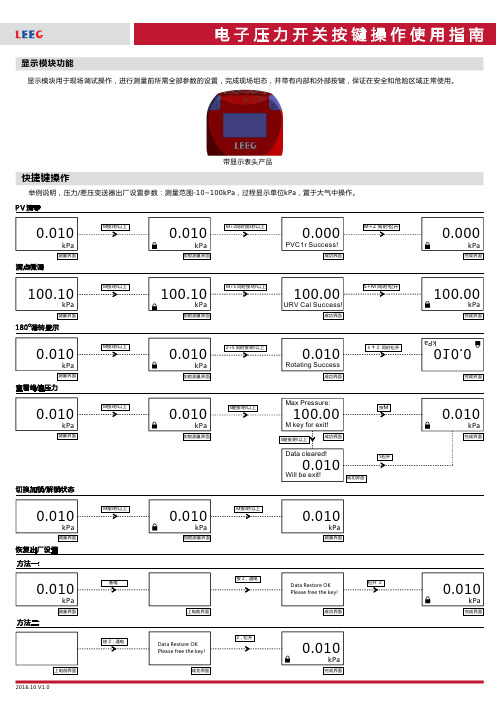
快捷键操作显示模块功能显示模块用于现场调试操作,进行测量前所需全部参数的设置,完成现场组态,并带有内部和外部按键,保证在安全和危险区域正常使用。
举例说明,压力/差压变送器出厂设置参数:测量范围-10~100kPa 过程显示单位置于大气中操作。
,,kPa 带显示表头产品详细操作说明第一路晶体管输出参数设置第二路晶体管输出参数设置显示隐藏参数方法一:详细操作说明参数表方法二:上述操作完成后,按键依次进入---参数设置,之后再次按下键进入隐藏参数设置M DisMod LRV URV Unit M 注:可用参数控制产品输出固定电流,从而确认产品电流输出电路是否正常,通过键修改固定电流值,并通过健确认即可。
1FixCOut S Z 注:可用参数手动控制两路晶体管状态,从而确认产品晶体管输出电路是否正常。
通过键修改晶体管输出状态,并通过键确认即可。
2FixTOut S ZDisplay module is used for field adjustment, all the parameters setting before measuring, complete site configuration.For example,Factory setting parameters: pressure range -10-100kPa, display unit kPa, operate in the atmosphere.Products with OLED displayAfter above operation, press M get into DisMod-LRV-Unit parameters setting,and press M again get into hidden parameters settingNote 1:Use FixCOut parameters to control fixed current ,to confirm whether current output is ok. Changing fixed current value by press S and confirm by Z.Note 2:Use FixTOut parameters to control 2 way PNP by mannual operation, to confirm whether PNP output is ok. Changing fixed current value by press S and confirm by Z.。
ZISE30A中文说明书

No.PS※※-OML0002CN-G 使用说明书产 品 名 称数字式压力开关形式/系列/型号ZSE30A(F)ISE30A目录安全注意事项 2型式表示·型号体系 8产品各部的名称及功能 10用语说明 11安装・设置 14设置方法 14配管方法 17配线方法 18压力的设定 21什么是测试模式 21功能设定 24什么是功能选择模式 24出厂设定 24 F0 单位切换功能 26 F1 OUT1的设定 27 F2 OUT2的设定 30 F3 响应时间的设定 30 F4显示分辨率的设定 31 F5 自动预设功能的设定 32 F6 显示值微调的设定 34 F7 省电模式的设定 35 F8 密码输入的设定 36特殊功能的设定 37 F90 全功能的设定 37 F97 复制功能的选择 39 F98 输出确认 41 F99 恢复出厂设置 43其他设定 44维护 47忘记密码的情况 48故障一览表 49规格 56规格表 56外形尺寸图 58安全注意事项此处所示的注意事项是为了确保您能安全正确地使用本产品,预先防止对您和他人造成危害和损失而制定的。
这些注意事项,按照危害和损伤的大小及紧急程度分为「注意」「警告」「危险」三个等级。
无论哪个都是与安全相关的重要内容,所以除了遵守国际规格(ISO/IEC)、日本工业规格(JIS)※1)以及其他安全法规※2)外,这些内容也请务必遵守。※1) ISO 4414: Pneumatic fluid power -- General rules relating to systemsISO 4413: Hydraulic fluid power -- General rules relating to systemsIEC 60204-1: Safety of machinery -- Electrical equipment of machines (Part 1: General requirements) ISO 10218-1992: Manipulating industrial robots-SafetyJIS B 8370: 空气压系统通则JIS B 8361: 油压系统通则JIS B 9960-1: 机械类的安全性、机械的电气装置(第1部: 一般要求事项)JIS B 8433-1993: 产业用操作机器人-安全性等※2) 劳动安全卫生法等注意:误操作时,有人员受伤的风险,以及物品破损的风险。警告:误操作时,有人员受到重大伤害甚至死亡的风险。
PS20
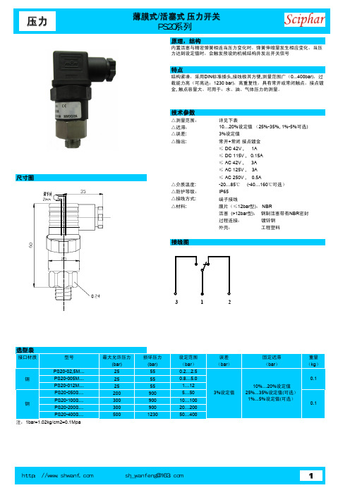
力达到设定值时,会触发预设的机械结构并发出开关信号
载能力高(可高达:1230 bar),高重复性,具有常开或常闭触点,接点镀金,触点容量大。
可用于:水、油、气体压力的测量。
△迟滞:10…20%设定值(25%-35%, 1%-5%可选)△误差:3%设定值
△输出:
常开+常闭接点镀金≤ DC 42V , 1A ≤ DC 115V , 0.15A ≤ AC 42V , 3A ≤ AC 125V , 3A
≤ AC 250V , 0.5A
△介质温度:-20…85℃ (-40…160℃可选)△防护等级:IP65
△接线方式:端子接线
△材料:
膜片(≤12bar 型): NBR
活塞 (>12bar 型):钢制活塞带有NBR 密封过程连接:镀锌钢外壳:
工程塑料
1.
型号各项是否与您所需一致2.量程是否正确
3.输出信号的种类和数量是否正确
4.是否有可选项、附件漏选
气体。
PSE54 数字式压力开关 中文说明书
精度 无标记 ±2%F.S.
A ±1%F.S.
管连接口径 M3 M3×0.5 M5 M5×0.8 01 R1/8(带 M5 内螺纹) N01 NPT1/8(带 M5 内螺纹) R04 φ4 减压阀 R06 φ6 减压阀 IM5 M5 内螺纹贯通 IM5H M5 内螺纹贯通(带安装孔)
• 选购件产品的型号 选购件产品
• 压力端口不可插入铁丝等异物。 否则可能引起压力传感器故障、误动作。
• 如果使用市场上销售的开关电源,必须将 FG 端子接地。 • 在开关电源与本传感器之间,请插入静噪滤波器(线路静噪滤波器、铁素体等)。
-4-
No.PS※※-OMG0003-B
○ 配线
• 配线时,应避免对电缆进行反复弯曲或施加拉伸力。 如果电缆承受反复弯曲应力和拉伸力,则有可能造成断线。 当导线受损时,应更换新品。
-5-
No.PS※※-OMG0003-B
○ 调整、使用 • 不可使负荷短路。 否则会导致压力传感器破损。 • 当检测出有微小的压力存在时,应预热 20~30 分钟。 如果在电源开启后立即检测,会有±1%的显示误差。
○ 维护、检查 • 维护、检查应在切断供电电源后进行。 否则可能导致系统构成设备出现意想不到的误动作。 • 维护、检查应定期进行。 一旦压力传感器出现误动作,就可能导致系统构成设备产生误动作。 • 维护、检查结束后应进行适当的功能检查。 如果发生设备不能正常动作等异常情况,应立即停止运行。 否则可能导致系统构成设备出现意想不到的误动作。 • 清扫压力传感器机身时不可使用汽油、稀释剂之类的有机溶剂。 否则可能导致表面损伤、显示消失。 请用软布擦拭。污迹严重时,应以软布蘸满中性清洗剂,拧干水分后擦拭、以除去污迹,最后用 干布再次擦拭。
数字式压力开关ISE50资料
-3-
No.PS※※-OMF0011CN-A
■安装使用上的希望 进行数字式压力开关的设计·选定·安装使用时,请遵守下述的内容。 ●关于设计·选定方面
请遵守下述与安使用相关的安装·配线·使用环境·调整·使用·维护保养等方面的内容。 ○产品规格 ·由于产品不同使用的流体也不同,因此必须确认产品规格。
· 原子能发电站的主机控制系统,原子能设施的安全保护系统,以及其他安全上的重要的系统和体系。 · 集团运输体系的操作控制系统和航空管制控制系统 · 直接与饮料·食品相接触的机器・装置
* 3: 特别的考虑是指,与本公司进行充分的商议,以构筑安全的系统(误操作处理功能设计、安全保障设计、冗余设计等)。
● 为了防止本产品由于环境疲劳(时效)等原因所发生的故障·误动作而引起的危害·损害,请实施具有安全性及 保全性的特别的考虑(*4)。
■标记的说明 表示
意义
警告 误操作时,可能会造成使用者重伤甚至死亡的危害程度。
注意 *1
*2
误操作时,有使用者被伤害的可能性,或者有物品损害的可能性。
*1:伤害是指,受伤、烫伤及触电等,不需要住院治疗或长期检查的受伤程度。
*2:物品损害是指,涉及到房屋、财产等的损害。
■图形记号的说明 图形记号
意义
禁止(绝对不可以)。 具体的禁止内容在图形记号中或者图形记号附近,用图和文字揭示。
刚接通电源后,会发生显示部的零点漂移,范围在±1%F.S.以内。 显示会因静电等干扰而变化。
○维护保养 ·维护保养时,应切断电源,停止供气,排除掉配管中的残余压缩空气,确认处于大气开放状态后进行。
否则有可能造成系统构成机器无目的的误动作。
·请定期实施维护保养。
由于压力开关的误动作,有可能造成系统构成机器无目的的误动作。
艾默生TI系列膨胀阀

H20PS系列小型压力开关
概述:
H20PS(M)系列压力开关是一种微型压力开关,它随被控介质的压力升降而使控制电路闭合或断开.广泛用于制冷机组,空调,油泵,气泵以及其它需要自行调节介质压力,保护压力系统的工业设备中.
工作原理:
艾默生
可换阀芯的TI(S)(E)热力膨胀阀是专为制冷应用而设计的,它适用于超市冷柜,陈列柜,冰淇淋机,冷库和冷藏车等.TI(S)(E)膨胀阀可灵活选择制冷量,能在宽广的和蒸发温度范围内进行稳定和精确的控制.
特点:
1,有八种不锈钢阀芯可供选择,适用于不同的制冷量
2,附可清洗更换的进管滤网
3,在不同的使用场合均可保持均一的过热度
4,大膜片设计使阀口的控制更顺滑的稳定
5,提供不同的充注以配合不同的用途
6,防腐,防锈的不锈钢阀体
7,分别有内/外平衡式可供选择
8,可带焊接连接头方便安装
9,静态过热度可适用调整
10,可提供特殊感温包充注。
29PS系列手动复位压力开关说明书

Page 129PS SERIES | MANUAL RESET PRESSURE SWITCHESFeaturesIntroductionApplicationsOperationProduct Features• Manual Reset • Snap-acting, trip free mechanism • Single-pole, single-throw switch, normally closed • Factory calibrated pressure setpoints from 200 to 750 psig (14 to 52 bar)• Tamper resistantThe 29PS Series is a manual reset, single pole, single throw, snap acting pressure switch. The 29PS is based on Sensata Technologies’ 20PS pressure switch, long recognized as an industry standard control device. Features of this switch include manual reset, a broad assortment of port fittings and electrical connections, and the option of a panel mount or line mount design.Sensata Technologies has been a leading global supplier of pressure sensors and switches for over 50 years.The Model 29PS pressure switch is primarily applied as an upper limit control on unitary and central air conditioning systems, heat pumps, roof top units, and refrigeration systems.This hermetic pressure switch employs a trip-free manual reset function, providing high reliability in an environmentally sealed, low-cost package.The 29PS utilizes a snap-acting stainless steel Klixon ® disc that reverses its curvature when pressurized above a customer specified actuation pressure. When the disc snaps, it opens a set of electrical contacts by means of a transfer pin. Resetting of the switch must be accomplished manually by pressing the integrated reset button.The unique latching mechanism in the 29PS design assures safe electrical cutout even if the reset button is held firmly depressed.This “trip-free” design prevents the consumer from restarting the equipment until the line pressure has dropped below the release setpoint. Without this “trip-free” mechanism, the equipment could be restarted by simply holding the reset button in the depressed position, while an overpressure condition remains.The welded, hermetic design of the 29PS provides increased reliability and maintenance-free operation for the lifetime of the switch. The actuation and release pressures of the disc are factory calibrated, simplifying installation and making the 29PS tamper resistant.The epoxy potting and rubber boot provide an environmental seal for the switch mechanism, protecting it from dust, oil and moisture. The 29PS is built into a vibration resistant package.Its compact size coupled with a wide variety of threaded and brazed pressure connections allows the 29PS to be mounted wherever is most appropriate for the application; inside a control box or out in the elements. Panel-mounted devices are typically provided with capillary tubes to allow for convenient access to the reset button. A variety of line-mounted fittings are available to simplify installation. Many different lead termination options are available for maximumflexibility.DESIGN SPECIFICATIONS All dimensions in millimeters [Inches].TYPICAL DIMENSIONAL DRAWINGSPage 2Page 3CONTACT US Rev:06/26/18Sensata Technologies, Inc. (“Sensata”) data sheets are solely intended to assist designers (“Buyers”) who are developing systems that incorporate Sensata products (also referred to herein as “components”). Buyer understands and agrees that Buyer remains responsible for using its independent analysis, evaluation and judgment in designing Buyer’s systems and products. Sensata data sheets have been created using standard laboratory conditions and engineering practices. Sensata has not conducted any testing other than that specifically described in the published documentation for a particular data sheet. Sensata may make corrections, enhancements, improvements and other changes to its data sheets or components without notice.Buyers are authorized to use Sensata data sheets with the Sensata component(s) identified in each particular data sheet. HOWEVER, NO OTHER LICENSE, EXPRESS OR IMPLIED, BY ESTOPPEL OR OTHERWISE TO ANY OTHER SENSATA INTELLECTUAL PROPERTY RIGHT, AND NO LICENSE TO ANY THIRD PARTY TECHNOLOGY OR INTELLECTUAL PROPERTY RIGHT, IS GRANTED HEREIN. SENSATA DATA SHEETS ARE PROVIDED “AS IS”. SENSATA MAKES NO WARRANTIES OR REPRESENTATIONS WITH REGARD TO THE DATA SHEETS OR USE OF THE DATA SHEETS, EXPRESS, IMPLIED OR STATUTORY, INCLUDING ACCURACY OR COMPLETENESS. SENSATA DISCLAIMS ANY WARRANTY OF TITLE AND ANY IMPLIED WARRANTIES OF MERCHANTABILITY, FITNESS FOR A PARTICULAR PURPOSE, QUIET ENJOYMENT, QUIET POSSESSION, AND NON-INFRINGEMENT OF ANY THIRD PARTY INTELLECTUAL PROPERTY RIGHTS WITH REGARD TO SENSATA DATA SHEETS OR USE THEREOF.All products are sold subject to Sensata’s terms and conditions of sale supplied at SENSATA ASSUMES NO LIABILITY FOR APPLICATIONS ASSISTANCE OR THE DESIGN OF BUYERS’ PRODUCTS. BUYER ACKNOWLEDGES AND AGREES THAT IT IS SOLELY RESPONSIBLE FOR COMPLIANCE WITH ALL LEGAL, REGULATORY AND SAFETY-RELATED REQUIREMENTS CONCERNING ITS PRODUCTS, AND ANY USE OF SENSATA COMPONENTS IN ITS APPLICATIONS, NOTWITHSTANDING ANY APPLICATIONS-RELATED INFORMATION OR SUPPORT THAT MAY BE PROVIDED BY SENSATA.Mailing Address: Sensata Technologies, Inc., 529 Pleasant Street, Attleboro, MA 02703, USA.Americas +1 (800) 350 2727***************************************Europe, Middle East & Africa +359 (2) 809 1826****************************Asia Pacific *************************.com China +86 (21) 2306 1500Japan +81 (45) 277 7117Korea +82 (31) 601 2004India +91 (80) 67920890Rest of Asia +886 (2) 27602006 ext 2808AGENCY APPROVALS AND CERTIFICATIONSWARNINGSHAZARD OF ELECTRIC SHOCK, EXPLOSION OR ARC FLASH • Disconnect all power before installing or working with this equipment • Verify all connections and replace all covers before turning on powerFailure to follow these instructions will result in death or serious injury。
普利司通PSE575 576 577压力传感器使用说明书

文件No.PS※※-OMT0005CN-A 使用说明书产品名称通用流体用压力传感器形式/系列/型号PSE575/576/577目录安全注意事项2型式表示・型号体系8 产品各部分名称及使用注意事项9安装・设置10配线方法10故障一览表12规格13规格表13外形尺寸图15安全注意事项此处所示的注意事项是为了确保您能安全正确地使用本产品,预先防止对您和他人造成危害和伤害而制定的。
这些注意事项,按照危害和损伤的大小及紧急程度分为“注意”“警告”“危险”三个等级。
无论哪个等级都是与安全相关的重要内容,所以除了遵守国际规格(ISO/IEC)、日本工业规格(JIS)※1)以及其他安全法规※2)外,这些内容也请务必遵守。*1) ISO 4414: Pneumatic fluid power -- General rules relating to systemsISO 4413: Hydraulic fluid power -- General rules relating to systemsIEC 60204-1: Safety of machinery -- Electrical equipment of machines (Part 1: General requirements) ISO 10218: Manipulating industrial robots-SafetyJIS B 8370: 空气压系统通则JIS B 8361: 油压系统通则JIS B 9960-1: 机械类的安全性、机械的电气装置(第1部:一般要求事项)JIS B 8433: 产业用操作机器人-安全性等*2)高压气体保护法、劳动安全卫生法等注意误操作时,有人员受伤的风险,以及物品破损的风险。警告误操作时,有人员受到重大伤害甚至死亡的风险。
危险在紧迫的危险状态下,如不回避会有人员受到重大伤害甚至死亡的风险。
警告①本产品的适合性请由系统设计者或规格制定者来判断。
燃烧安全控制

北京润瓯科技有限公司燃烧安全控制产品手册2010 年3月第二版公司简介燃烧控制产品目录(Contents)GIV –系列”A”级燃气电磁阀 (GIV- Class “A” Gas Valves, Normally Closed On/Off) GIV 10 (DN10) 螺纹连接“A”级燃气专用电磁阀Class “A” solenoid valve, thread connection.GIV 15 (DN15) 螺纹连接“A”级燃气专用电磁阀Class “A” soleno id valve, thread connection.GIV 20 (DN20) 螺纹连接“A”级燃气专用电磁阀Class “A” solenoid valve, thread connection.GIV 25 (DN25) 螺纹连接“A”级燃气专用电磁阀Class “A” solenoid valve, thread connection.GIV 40 (DN40) 螺纹连接“A”级燃气专用电磁阀Class “A” solenoid valve, thread connection GIV 50 (DN50) 螺纹或法兰连接“A”级燃气专用电磁阀Class “A” solenoid valve, thread or flange connectionGIV 65 (DN65) 螺纹或法兰连接“A”级燃气专用电磁阀Class “A” solenoid valve, thread or flange connectionFC –系列燃烧安全程序控制器 (Combustion Controllers)FC04 火焰开关控制器 (Flame Switch)FC05 工业燃烧器用控制器 (Industrial flame controller, with combustion program) FC06 中小型商用锅炉燃烧程序控制器(Commercial or industrial flame controller, with combustion program) KC141 工业炉专用燃烧程序控制器 (Special designing for industrial kilns andfurnaces applications)RC224R 家或商用安全电压燃烧程序控制器(Special designing for low voltage (24Vac) residential and commercial applications)FUVS –系列紫外线型火焰检测器 (UV Series Flame Detectors)FUVS100高等级防护,螺纹连接,轴向观测型;(IP65, G1/2” connection, end viewing) FUVS110 插拔式,侧向观测型; (Side viewing)FUVS200 高等级防护,螺纹连接,轴向观测型 (IP65, G3/4” connection, end viewing) FUVS250大口径,螺纹连接,轴向观测型 (IP65, G1” connection,end viewing)PS –系列燃气、空气压力开关 (Gas or Air Pressure Switches)PS 0212 低压压力开关;调节范围 (Range):2-12mbarPS 1050中压压力开关;调节范围 (Range):10-50mbarPS 3015高压压力开关;调节范围 (Range):30-150mbarEBI –系列燃气、轻油电子高压点火器 (Electronic Igniters)EBI-A 单极、燃气高压电子点火器 (One pole gas igniter)EBI-B 双极、燃油高压电子点火器 (Two poles oil igniter)SIF –单针点火隔离器 (Isolation device of using one rod to ignite and detect flame)GIV10/15/20/25系列”A ”级、直动式、燃气专用电磁阀北京润瓯科技有限公司图2 GIV10/15/20/25 系列阀门外形尺寸图(mm)应用:GIV 系列“A ”级燃气电磁阀可用于燃气燃烧器、工业炉、焚烧炉等加热设备的燃气控制与调节 。
- 1、下载文档前请自行甄别文档内容的完整性,平台不提供额外的编辑、内容补充、找答案等附加服务。
- 2、"仅部分预览"的文档,不可在线预览部分如存在完整性等问题,可反馈申请退款(可完整预览的文档不适用该条件!)。
- 3、如文档侵犯您的权益,请联系客服反馈,我们会尽快为您处理(人工客服工作时间:9:00-18:30)。
设定值 锁紧螺母
不锈钢激光标牌 全压铸铝外壳 设定简单可靠
原装进口全焊接膜片 杜绝泄漏
316L不锈钢接液材质
产品选型指南
■ 控制器 / 压力开关
特点 应用
适合各类工业现场能够理想的替代国外同类产品 进口橡胶/36L不锈钢膜片/活塞式传感器,性能稳定可靠 精度:±%; 重复性:±.%; 结构简单,无可拆卸部件 SPDT或DPDT输出;铸铝外壳,可选防爆;多种压力及电气接口可选 量程:600Pa~0MPபைடு நூலகம்可选
PS系列压力控制器系列产品广泛应用在石油、化工、冶金、电力、制糖、制药等各行业需 要压力控制的场所,在自动化控制系统中起压力保护的作用。其中全焊接不锈钢膜片是目前 应用最多,可靠性最好的压力保护方式,全焊接模式能够有效的防止漏液和误动作;有较强 的抗腐蚀性;金属波纹管式控制器广泛用于以上行业各种腐蚀气体和液体,能够做到比不锈 钢膜片式更高的压力;橡胶膜片式控制器用于中性气体和液体介质,主要应用于微压和微差 压测量。目前,我们的能够提供从负压至40MPa量程可选的各段控制值的开关,能够完全替 代国外同类产品。所有量程段产品我们都能够提供现货,并保证质量。同时我们可以根据现 场要求,提供非标准产品。 PS系列压力控制器的微动开关经过100,000次循环的实验,所有传感器都经过耐压,振动 和冲击试验。 电压、电流、功率或直流等都可根据现场要求订做。
2 产品选型指南
■ 控制器 / 压力开关
产品选型指南 3
■ 控制器 / 压力开关
产品选型指南
■ 控制器 / 压力开关
产品选型指南
■ 控制器 / 压力开关
6 产品选型指南
